EP3758196B1 - Verbindungsring für motorwicklung - Google Patents
Verbindungsring für motorwicklung Download PDFInfo
- Publication number
- EP3758196B1 EP3758196B1 EP20174733.4A EP20174733A EP3758196B1 EP 3758196 B1 EP3758196 B1 EP 3758196B1 EP 20174733 A EP20174733 A EP 20174733A EP 3758196 B1 EP3758196 B1 EP 3758196B1
- Authority
- EP
- European Patent Office
- Prior art keywords
- termination
- coupling member
- stator
- winding
- electrically insulating
- Prior art date
- Legal status (The legal status is an assumption and is not a legal conclusion. Google has not performed a legal analysis and makes no representation as to the accuracy of the status listed.)
- Active
Links
Images





Classifications
-
- H—ELECTRICITY
- H02—GENERATION; CONVERSION OR DISTRIBUTION OF ELECTRIC POWER
- H02K—DYNAMO-ELECTRIC MACHINES
- H02K1/00—Details of the magnetic circuit
- H02K1/06—Details of the magnetic circuit characterised by the shape, form or construction
- H02K1/12—Stationary parts of the magnetic circuit
-
- H—ELECTRICITY
- H02—GENERATION; CONVERSION OR DISTRIBUTION OF ELECTRIC POWER
- H02K—DYNAMO-ELECTRIC MACHINES
- H02K3/00—Details of windings
- H02K3/46—Fastening of windings on the stator or rotor structure
- H02K3/52—Fastening salient pole windings or connections thereto
- H02K3/521—Fastening salient pole windings or connections thereto applicable to stators only
- H02K3/522—Fastening salient pole windings or connections thereto applicable to stators only for generally annular cores with salient poles
-
- H—ELECTRICITY
- H02—GENERATION; CONVERSION OR DISTRIBUTION OF ELECTRIC POWER
- H02K—DYNAMO-ELECTRIC MACHINES
- H02K3/00—Details of windings
- H02K3/02—Windings characterised by the conductor material
-
- H—ELECTRICITY
- H02—GENERATION; CONVERSION OR DISTRIBUTION OF ELECTRIC POWER
- H02K—DYNAMO-ELECTRIC MACHINES
- H02K3/00—Details of windings
- H02K3/04—Windings characterised by the conductor shape, form or construction, e.g. with bar conductors
- H02K3/28—Layout of windings or of connections between windings
-
- H—ELECTRICITY
- H02—GENERATION; CONVERSION OR DISTRIBUTION OF ELECTRIC POWER
- H02K—DYNAMO-ELECTRIC MACHINES
- H02K3/00—Details of windings
- H02K3/32—Windings characterised by the shape, form or construction of the insulation
- H02K3/38—Windings characterised by the shape, form or construction of the insulation around winding heads, equalising connectors, or connections thereto
-
- H—ELECTRICITY
- H02—GENERATION; CONVERSION OR DISTRIBUTION OF ELECTRIC POWER
- H02K—DYNAMO-ELECTRIC MACHINES
- H02K3/00—Details of windings
- H02K3/46—Fastening of windings on the stator or rotor structure
- H02K3/50—Fastening of winding heads, equalising connectors, or connections thereto
-
- H—ELECTRICITY
- H02—GENERATION; CONVERSION OR DISTRIBUTION OF ELECTRIC POWER
- H02K—DYNAMO-ELECTRIC MACHINES
- H02K5/00—Casings; Enclosures; Supports
- H02K5/04—Casings or enclosures characterised by the shape, form or construction thereof
- H02K5/22—Auxiliary parts of casings not covered by groups H02K5/06-H02K5/20, e.g. shaped to form connection boxes or terminal boxes
- H02K5/225—Terminal boxes or connection arrangements
-
- B—PERFORMING OPERATIONS; TRANSPORTING
- B60—VEHICLES IN GENERAL
- B60K—ARRANGEMENT OR MOUNTING OF PROPULSION UNITS OR OF TRANSMISSIONS IN VEHICLES; ARRANGEMENT OR MOUNTING OF PLURAL DIVERSE PRIME-MOVERS IN VEHICLES; AUXILIARY DRIVES FOR VEHICLES; INSTRUMENTATION OR DASHBOARDS FOR VEHICLES; ARRANGEMENTS IN CONNECTION WITH COOLING, AIR INTAKE, GAS EXHAUST OR FUEL SUPPLY OF PROPULSION UNITS IN VEHICLES
- B60K6/00—Arrangement or mounting of plural diverse prime-movers for mutual or common propulsion, e.g. hybrid propulsion systems comprising electric motors and internal combustion engines
- B60K6/20—Arrangement or mounting of plural diverse prime-movers for mutual or common propulsion, e.g. hybrid propulsion systems comprising electric motors and internal combustion engines the prime-movers consisting of electric motors and internal combustion engines, e.g. HEVs
- B60K6/22—Arrangement or mounting of plural diverse prime-movers for mutual or common propulsion, e.g. hybrid propulsion systems comprising electric motors and internal combustion engines the prime-movers consisting of electric motors and internal combustion engines, e.g. HEVs characterised by apparatus, components or means specially adapted for HEVs
- B60K6/26—Arrangement or mounting of plural diverse prime-movers for mutual or common propulsion, e.g. hybrid propulsion systems comprising electric motors and internal combustion engines the prime-movers consisting of electric motors and internal combustion engines, e.g. HEVs characterised by apparatus, components or means specially adapted for HEVs characterised by the motors or the generators
-
- B—PERFORMING OPERATIONS; TRANSPORTING
- B60—VEHICLES IN GENERAL
- B60Y—INDEXING SCHEME RELATING TO ASPECTS CROSS-CUTTING VEHICLE TECHNOLOGY
- B60Y2200/00—Type of vehicle
- B60Y2200/90—Vehicles comprising electric prime movers
- B60Y2200/91—Electric vehicles
-
- B—PERFORMING OPERATIONS; TRANSPORTING
- B60—VEHICLES IN GENERAL
- B60Y—INDEXING SCHEME RELATING TO ASPECTS CROSS-CUTTING VEHICLE TECHNOLOGY
- B60Y2200/00—Type of vehicle
- B60Y2200/90—Vehicles comprising electric prime movers
- B60Y2200/92—Hybrid vehicles
-
- B—PERFORMING OPERATIONS; TRANSPORTING
- B60—VEHICLES IN GENERAL
- B60Y—INDEXING SCHEME RELATING TO ASPECTS CROSS-CUTTING VEHICLE TECHNOLOGY
- B60Y2400/00—Special features of vehicle units
- B60Y2400/60—Electric Machines, e.g. motors or generators
-
- H—ELECTRICITY
- H02—GENERATION; CONVERSION OR DISTRIBUTION OF ELECTRIC POWER
- H02K—DYNAMO-ELECTRIC MACHINES
- H02K2203/00—Specific aspects not provided for in the other groups of this subclass relating to the windings
- H02K2203/09—Machines characterised by wiring elements other than wires, e.g. bus rings, for connecting the winding terminations
Definitions
- the present invention relates to a stator assembly for an electric motor.
- a rotating magnetic field is generated within the motor's stator assembly, resulting in rotation of the motor's rotor assembly.
- the rotating magnetic field is generated by a plurality of circumferentially distributed windings that are mounted within a plurality of circumferentially distributed stator slots and teeth.
- the windings which may be comprised of round or rectangular wire, are divided into coil groups, each of which represents a single pole of a single phase.
- Each phase of the coil windings terminate into a connector, commonly referred to as a lug, which is used to couple the coil windings to an AC power source.
- a lug which is used to couple the coil windings to an AC power source.
- stator manufacturing process In a typical stator manufacturing process, distributing the windings within the stator assembly is a rapid process utilizing an automated CNC (computer numerical control) winding machine. Once the stator windings are completed, they must be coupled to the stator lugs. During this portion of the stator manufacturing process the wire bundles are routed, insulation sleeves are added, and the lugs are resistance welded to the wire bundles. As this portion of the process is performed by hand, it is quite slow and adds considerable expense to the stator assembly. Accordingly, what is needed is a stator manufacturing process that minimizes or eliminates the need for manually performing the final steps associated with coupling the windings to the lugs, thereby providing a more cost effective stator assembly. The present invention provides a system and manufacturing process that achieves these goals while also providing a more versatile stator assembly that may be configured to meet a variety of torque and power requirements.
- CNC computer numerical control
- DE 10 2016 114723 A1 discloses an electrical, essentially ringshaped connection device for a stator of an electric motor with a retracted round wire winding, comprising: an electrically insulating base ring ; an electrically conductive star ring resting thereon and having a plurality of radially outwardly extending outer connection contacts; three structurally identical pairs, each having a lower, electrically insulating intermediate ring and an upper electrically conductive connection ring resting thereon with outer connection contacts extending radially outward and with one extending from its radially inner side in the axial direction upwardly extending, upper connection contact; and a substantially annular cover which covers the upper connection ring, from which the three upper connection contacts of the electrically conductive connection rings protrude upwards and which covers the outer connection contacts radially outwards; wherein the three pairs of electrically insulating intermediate rings and electrically conductive connection rings are arranged offset from one another in the circumferential direction so that their outer connection contacts are each at connection positions spaced from one
- WO 2018/179790 A1 discloses a phase busbar unit provided with: a busbar holder made of an insulator and supporting a plurality of phase busbars of a motor that rotates around the center axis thereof; and a busbar cover made of an insulator and fixed to the busbar holder while covering at least one axial side of each of the busbars.
- Each of the busbars includes: a base part; a plurality of extension parts extending radially outward from the base part; and terminals provided on radially outer end portions of the extension parts.
- the busbar cover includes a plurality of protrusion parts protruding toward the other axial side, wherein the plurality of the protrusion parts contact the busbars, and at least one of the protrusion parts contacts the base part in the vicinity of the extension parts.
- EP 2 824 765 A1 discloses wire connection member for connecting a first wire to a second wire by crimping includes a partition for dividing a first housing space for housing tip portions of the first wire from a second housing space for housing a tip portion of the second wire, a first housing portion that, together with the partition, forms the first housing space, and a second housing portion that, together with the partition, forms the second housing space.
- the partition is arranged between the first and second housing portions.
- WO 2011/108734 A1 discloses a busbar unit which is arranged on an axial end portion of a stator, and electrically connected with a plurality of coil wire terminals arranged to project in an axial direction above the axial end portion of the stator.
- the busbar unit includes a plurality of busbars each including a body portion defined by an electrically conductive wire shaped in a ring or the letter "C", the body portion being arranged around an axis of the stator; a holder member arranged on the axial end portion of the stator to hold the busbars; and a plurality of terminal members each including a busbar connection portion connected with the body portion of one of the busbars, and a coil connection portion connected with one of the coil wire terminals.
- each termination coupling member of each termination coupling member group may be (i) laser welded, (ii) TIG welded, (iii) resistance welded, and/or (iv) brazed to a different winding termination of the plurality of winding terminations during attachment of the pre-fabricated connector to the stator.
- each of the plurality of electrically insulating coupling member overlays may include a U-shaped end portion that is configured to partially surround a corresponding winding termination, and which may be crimped onto the corresponding winding termination during attachment of the pre-fabricated connector to the stator.
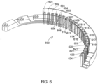
- the pre-fabricated connector as fabricated may further include a second plurality of termination coupling members divided into a second plurality of termination coupling member groups, where each termination coupling member of each termination coupling member group of the second plurality of termination coupling member groups is configured to be mechanically and conductively coupled to a different winding termination of the plurality of winding terminations, where each termination coupling member group of the second plurality of termination coupling member groups is mechanically and conductively coupled to one of a plurality of lugless bus bars, and where the electrically insulating material is configured to prevent electrical contact or partial discharge between the plurality of lugless bus bars, and to prevent electrical contact or partial discharge between the plurality of bus bars and the plurality of lugless bus bars.
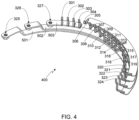
- Fig. 4 provides a perspective view of the electrically conductive connector portion 400 of connector 300.
- Fig. 5 provides a rear perspective view of connector portion 400.
- Bus bars 501-503 are connected to lugs 325-327, respectively.
- each bus bar 501-503 is connected to four winding terminations.
- bus bar 503 and therefore lug 327 is connected to termination coupling members 301-304 which, in turn, are connected to winding terminations 101-104 when the connector is attached to the stator windings.
Landscapes
- Engineering & Computer Science (AREA)
- Power Engineering (AREA)
- Insulation, Fastening Of Motor, Generator Windings (AREA)
- Manufacture Of Motors, Generators (AREA)
Claims (14)
- Eine Statoranordnung für einen Elektromotor, umfassend:einen Stator (100) mit einer Vielzahl von Wicklungen, die umlaufend um den Stator (100) verteilt sind, wobei die Vielzahl von Wicklungen in einer Vielzahl von Wicklungsanschlüssen (101-124) endet; undeinen vorgefertigten Verbinder (300), der über die Vielzahl von Wicklungsanschlüssen (101-124) mit dem Stator (100) verbunden ist, wobei der vorgefertigte Verbinder (300) vor der Befestigung am Stator (100) gefertigt wurde, wobei der vorgefertigte Verbinder (300) in gefertigtem Zustand umfasst:eine erste Vielzahl von Anschlusskupplungselementen (301-304, 309-312, 317-320), unterteilt in eine erste Vielzahl von Gruppen von Anschlusskupplungselementen, wobei jedes Anschlusskupplungselement jeder Gruppe der ersten Vielzahl von Gruppen von Anschlusskupplungselementen so konfiguriert ist, dass es mechanisch und leitend mit einem unterschiedlichen Wicklungsanschluss der Vielzahl von Wicklungsanschlüssen (101-124) verbunden werden kann, wobei jede Gruppe von Anschlusskupplungselementen mechanisch und leitend mit einer von mehreren Stromschienen (501-503) verbunden ist, und wobei jede Stromschiene der Vielzahl von Stromschienen (501-503) einen unabhängigen Anschlusszapfen (325-327) umfasst; undein elektrisch isolierendes Material (600), das Abschnitte der Vielzahl von Stromschienen (501-503) überdeckt, wobei das elektrisch isolierende Material (600) so konfiguriert ist, dass es einen Kontakt zwischen der Vielzahl von Stromschienen (501-503) verhindert;dadurch gekennzeichnet, dasseine Vielzahl von elektrisch isolierenden Überzügen für Anschlusskupplungselemente (601-624) vorgesehen ist, wobei die Vielzahl von elektrisch isolierenden Überzügen für Anschlusskupplungselemente (601-624) so konfiguriert ist, dass sie einen Kontakt zwischen der ersten Vielzahl von Anschlusskupplungselementen (301-304, 309-312, 317-320) verhindert.
- Die Statoranordnung nach Anspruch 1, wobei jedes Anschlusskupplungselement (301-304, 309-312, 317-320) jeder Gruppe der ersten Vielzahl von Gruppen von Anschlusskupplungselementen (i) lasergeschweißt, (ii) mit Wolfram-Inertgas (WIG) geschweißt, (iii) widerstandsgeschweißt oder (iv) hartgelötet mit dem jeweiligen unterschiedlichen Wicklungsanschluss der Vielzahl von Wicklungsanschlüssen (101-124) während der Befestigung des vorgefertigten Verbinders (300) am Stator (100) verbunden ist.
- Die Statoranordnung nach Anspruch 1, wobei jeder der Vielzahl von elektrisch isolierenden Überzügen für Anschlusskupplungselemente (601-624) ferner einen U-förmigen Abschnitt umfasst, der so konfiguriert ist, dass er einen entsprechenden Wicklungsanschluss der Vielzahl von Wicklungsanschlüssen (101-124) teilweise umgibt.
- Die Statoranordnung nach Anspruch 3, wobei jeder U-förmige Abschnitt während der Befestigung des vorgefertigten Verbinders (300) am Stator (100) auf den entsprechenden Wicklungsanschluss aufgecrimpt wird.
- Die Statoranordnung nach einem der Ansprüche 1 bis 4, wobei der vorgefertigte Verbinder (300) in gefertigtem Zustand ferner eine zweite Vielzahl von Anschlusskupplungselementen (305-308, 313-316, 321-324) umfasst, unterteilt in eine zweite Vielzahl von Gruppen von Anschlusskupplungselementen, wobei jedes Anschlusskupplungselement jeder Gruppe der zweiten Vielzahl von Gruppen von Anschlusskupplungselementen so konfiguriert ist, dass es mechanisch und leitend mit einem unterschiedlichen Wicklungsanschluss der Vielzahl von Wicklungsanschlüssen (101-124) verbunden werden kann, wobei jede Gruppe von Anschlusskupplungselementen der zweiten Vielzahl von Gruppen von Anschlusskupplungselementen mechanisch und leitend mit einer von mehreren stromzapfenlosen Stromschienen (504-507) verbunden ist, wobei das elektrisch isolierende Material (600) so konfiguriert ist, dass es einen Kontakt zwischen der Vielzahl von stromzapfenlosen Stromschienen (504-507) verhindert, und wobei das elektrisch isolierende Material (600) so konfiguriert ist, dass es einen Kontakt zwischen der Vielzahl von Stromschienen (501-503) und der Vielzahl von stromzapfenlosen Stromschienen (504-507) verhindert.
- Die Statoranordnung nach Anspruch 5, wobei jedes Anschlusskupplungselement (301-304, 309-312, 317-320) jeder Gruppe der ersten Vielzahl von Gruppen von Anschlusskupplungselementen (i) lasergeschweißt, (ii) mit Wolfram-Inertgas (WIG) geschweißt, (iii) widerstandsgeschweißt oder (iv) hartgelötet mit dem jeweiligen unterschiedlichen Wicklungsanschluss der Vielzahl von Wicklungsanschlüssen (101-124) während der Befestigung des vorgefertigten Verbinders (300) am Stator (100) verbunden ist, und wobei jedes Anschlusskupplungselement (305-308, 313-316, 321-324) jeder Gruppe der zweiten Vielzahl von Gruppen von Anschlusskupplungselementen während der Befestigung des vorgefertigten Verbinders (300) am Stator (100) lasergeschweißt mit dem jeweiligen unterschiedlichen Wicklungsanschluss der Vielzahl von Wicklungsanschlüssen (101-124) verbunden ist.
- Die Statoranordnung nach Anspruch 5, wobei die Vielzahl von elektrisch isolierenden Überzügen für Anschlusskupplungselemente (601-624) so konfiguriert ist, dass sie einen Kontakt zwischen der zweiten Vielzahl von Anschlusskupplungselementen (305-308, 313-316, 321-324) verhindert, und wobei die Vielzahl von elektrisch isolierenden Überzügen für Anschlusskupplungselemente (601-624) so konfiguriert ist, dass sie einen Kontakt zwischen der ersten Vielzahl von Anschlusskupplungselementen (301-304, 309-312, 317-320) und der zweiten Vielzahl von Anschlusskupplungselementen (305-308, 313-316, 321-324) verhindert.
- Die Statoranordnung nach Anspruch 7, wobei jeder der Vielzahl von elektrisch isolierenden Überzügen für Anschlusskupplungselemente (601-624) ferner einen U-förmigen Abschnitt umfasst, der so konfiguriert ist, dass er einen entsprechenden Wicklungsanschluss der Vielzahl von Wicklungsanschlüssen (101-124) teilweise umgibt.
- Die Statoranordnung nach Anspruch 8, wobei jeder U-förmige Abschnitt während der Befestigung des vorgefertigten Verbinders (300) am Stator (100) auf den entsprechenden Wicklungsanschluss aufgecrimpt wird.
- Die Statoranordnung nach einem der Ansprüche 1 bis 9, wobei jedes der ersten Vielzahl von Anschlusskupplungselementen (301-304, 309-312, 317-320) aus einem Kupfermaterial gefertigt ist, und wobei jede der Vielzahl von Stromschienen (501-503) aus dem Kupfermaterial gefertigt ist.
- Die Statoranordnung nach einem der Ansprüche 1 bis 10, wobei zumindest ein Teil der Vielzahl von Stromschienen (501-503) mit dem elektrisch isolierenden Material (600) umspritzt ist.
- Die Statoranordnung nach einem der Ansprüche 1 bis 11, wobei ein Kunststoffmaterial als das elektrisch isolierende Material (600) ausgewählt ist, das zur Herstellung des vorgefertigten Verbinders (300) verwendet wird.
- Die Statoranordnung nach einem der Ansprüche 1 bis 12, wobei die Vielzahl von Wicklungen aus Kupferdraht mit rundem oder rechteckigem Querschnitt besteht.
- Die Statoranordnung nach einem der Ansprüche 1 bis 13, wobei jede Stromschiene der Vielzahl von Stromschienen (501-503) einer Phase des Elektromotors entspricht.
Applications Claiming Priority (1)
| Application Number | Priority Date | Filing Date | Title |
|---|---|---|---|
| US16/453,029 US11133719B2 (en) | 2019-06-26 | 2019-06-26 | Motor winding connector ring |
Publications (2)
| Publication Number | Publication Date |
|---|---|
| EP3758196A1 EP3758196A1 (de) | 2020-12-30 |
| EP3758196B1 true EP3758196B1 (de) | 2025-07-02 |
Family
ID=70736757
Family Applications (1)
| Application Number | Title | Priority Date | Filing Date |
|---|---|---|---|
| EP20174733.4A Active EP3758196B1 (de) | 2019-06-26 | 2020-05-14 | Verbindungsring für motorwicklung |
Country Status (5)
| Country | Link |
|---|---|
| US (1) | US11133719B2 (de) |
| EP (1) | EP3758196B1 (de) |
| JP (2) | JP7041999B2 (de) |
| KR (1) | KR102386600B1 (de) |
| CN (2) | CN213341768U (de) |
Families Citing this family (8)
| Publication number | Priority date | Publication date | Assignee | Title |
|---|---|---|---|---|
| US11165301B2 (en) * | 2019-11-12 | 2021-11-02 | Borgwarner Inc. | Interior bus bar for electric machine winding |
| FR3121801B1 (fr) | 2021-04-07 | 2023-05-05 | Nidec Psa Emotors | Connecteur pour stator de machine électrique tournante |
| US12244197B2 (en) | 2021-07-14 | 2025-03-04 | Borgwarner Inc. | Stator with outer diameter bus bar connection |
| EP4447285A4 (de) * | 2021-12-16 | 2025-03-19 | Guangdong Welling Motor Manufacturing Co., Ltd. | Motor, leistungsanordnung und fahrrad mit hilfsantrieb |
| US12456893B2 (en) | 2022-08-29 | 2025-10-28 | Atieva, Inc. | Electric motor with unvarnished end winding for stator |
| DE102022123902B4 (de) * | 2022-09-19 | 2025-05-15 | Schaeffler Technologies AG & Co. KG | Modulares System zur Herstellung eines Stators für eine elektrische Maschine |
| WO2024216262A1 (en) | 2023-04-14 | 2024-10-17 | Garner Development Services, Llc | Caseless electric motor with a stationary shaft for marine enviroments |
| WO2024227054A1 (en) | 2023-04-27 | 2024-10-31 | Garner Development Services, Llc | Jet pump propulsion system |
Family Cites Families (20)
| Publication number | Priority date | Publication date | Assignee | Title |
|---|---|---|---|---|
| JP3700236B2 (ja) | 1996-03-01 | 2005-09-28 | 松下電器産業株式会社 | 電動機 |
| JP2000134851A (ja) | 1998-10-20 | 2000-05-12 | Matsushita Electric Ind Co Ltd | 電動機のステータ |
| US20030214190A1 (en) | 2002-05-15 | 2003-11-20 | Delco Remy America | Connection device for hairpin wound electric machines |
| US7187095B2 (en) * | 2004-02-24 | 2007-03-06 | Asmo Co., Ltd. | Motor, control circuit member and manufacturing method of motor |
| JP2008125170A (ja) | 2006-11-09 | 2008-05-29 | Toyota Motor Corp | 回転電機およびそのリード線端末の処理方法 |
| JP4855239B2 (ja) * | 2006-12-25 | 2012-01-18 | 三菱電線工業株式会社 | モータ用絶縁ハウジング |
| JP4939244B2 (ja) | 2007-01-31 | 2012-05-23 | アイチエレック株式会社 | 回転機用巻線接続装置、回転機用固定子及び回転機 |
| JP2008219972A (ja) * | 2007-02-28 | 2008-09-18 | Jtekt Corp | 電動モータ |
| JP2010011627A (ja) | 2008-06-26 | 2010-01-14 | Asmo Co Ltd | バスバー、バスバー装置、ステータ結合体、ブラシレスモータ、及びステータ結合体の製造方法 |
| JP4688910B2 (ja) * | 2008-08-08 | 2011-05-25 | 三菱電機株式会社 | 電動パワーステアリング装置用モータ |
| US8497617B2 (en) * | 2009-07-15 | 2013-07-30 | GM Global Technology Operations LLC | Stators with improved conductor assembly and method of making same |
| JP5703604B2 (ja) | 2010-03-03 | 2015-04-22 | 日本電産株式会社 | バスバーユニット及びモータ |
| US20130076175A1 (en) | 2011-09-22 | 2013-03-28 | Paul F. Turnbull | Connection module for a bar wound stator assembly and method of manufacturing a bar wound stator assembly |
| JP6190599B2 (ja) * | 2013-03-08 | 2017-08-30 | Kyb株式会社 | バスバーユニットの製造方法 |
| JP6024609B2 (ja) | 2013-07-09 | 2016-11-16 | 日立金属株式会社 | 集配電リング |
| JP6260358B2 (ja) | 2014-03-07 | 2018-01-17 | 日産自動車株式会社 | 集中巻きモータの配電部材 |
| DE112016000451T5 (de) | 2015-01-22 | 2017-11-09 | Jtekt Corporation | Elektromotoreinheit und Antriebseinheit für ein Fahrzeug |
| DE102016204935A1 (de) | 2016-03-24 | 2017-09-28 | Robert Bosch Gmbh | Verschaltungsplatte für einen Stator einer elektrischen Maschine und Verfahren zum Herstellen einer elektrischen Maschine |
| DE102016114723A1 (de) | 2016-08-09 | 2018-02-15 | Scherdel Innotec Forschungs- Und Entwicklungs-Gmbh | Elektrische, im Wesentlichen ringförmige Anschlussvorrichtung für einen Stator eines Elektromotors sowie Elektromotor |
| DE112018001656T5 (de) | 2017-03-31 | 2020-01-02 | Nidec Corporation | Sammelschieneneinheit und Motor, der diese aufweist |
-
2019
- 2019-06-26 US US16/453,029 patent/US11133719B2/en active Active
-
2020
- 2020-05-13 JP JP2020084796A patent/JP7041999B2/ja active Active
- 2020-05-13 KR KR1020200056861A patent/KR102386600B1/ko active Active
- 2020-05-14 EP EP20174733.4A patent/EP3758196B1/de active Active
- 2020-06-04 CN CN202021009536.7U patent/CN213341768U/zh not_active Expired - Fee Related
- 2020-06-04 CN CN202010498790.6A patent/CN112152336B/zh active Active
-
2022
- 2022-03-09 JP JP2022036212A patent/JP7554393B2/ja active Active
Also Published As
| Publication number | Publication date |
|---|---|
| JP7041999B2 (ja) | 2022-03-25 |
| JP2021005998A (ja) | 2021-01-14 |
| EP3758196A1 (de) | 2020-12-30 |
| US20200412195A1 (en) | 2020-12-31 |
| JP7554393B2 (ja) | 2024-09-20 |
| CN112152336A (zh) | 2020-12-29 |
| CN112152336B (zh) | 2023-11-07 |
| US11133719B2 (en) | 2021-09-28 |
| KR20210001913A (ko) | 2021-01-06 |
| JP2022091796A (ja) | 2022-06-21 |
| CN213341768U (zh) | 2021-06-01 |
| KR102386600B1 (ko) | 2022-04-15 |
Similar Documents
| Publication | Publication Date | Title |
|---|---|---|
| EP3758196B1 (de) | Verbindungsring für motorwicklung | |
| US11545867B2 (en) | Bus bar assembly for electric machine winding | |
| US11557934B2 (en) | Interior bus bar for electric machine winding | |
| EP1739809B1 (de) | Eine zentrale Energieverteilungsanordnung für einen bürstenlosen Motor, ein bürstenloser Motor damit und ein Verfahren zur Herstellung dafür | |
| JP5978357B2 (ja) | 回転電機 | |
| US8143752B2 (en) | Electric motor having electrical connecting elements for connection to winding leads | |
| US8497618B2 (en) | Stator for rotatry electrical machine including an insulating bobbin | |
| CN107431405B (zh) | 定子 | |
| US7205689B2 (en) | Electric motor with space-saving low-resistance neutral ring | |
| US8067867B2 (en) | Motor with neutral bus ring connecting multiple motor coils | |
| CN103368304A (zh) | 车载用电动机及使用了该车载用电动机的电动动力转向装置 | |
| US10938256B2 (en) | Motor stator and manufacturing method thereof | |
| CN103683618A (zh) | 配电部件和旋转电机 | |
| US10033238B2 (en) | Connection ring arrangement for an electrical machine | |
| CA2349237A1 (en) | Device for converting electric energy into a mechanical one and/or for doing the opposite and method for producing such a device | |
| JP2007174869A (ja) | インシュレータ、ステータアセンブリ、セグメントステータ、及び回転電機用ステータ | |
| KR101000621B1 (ko) | 자동차용 모터·제너레이터 | |
| JP2006187164A (ja) | 回転電機 | |
| CN115149671A (zh) | 定子和马达 | |
| CN220692477U (zh) | 一种汇流排及动力系统 | |
| KR102350229B1 (ko) | 구동 모터용 터미널 어셈블리 | |
| JP2002233095A (ja) | 電気機器 | |
| US20260088665A1 (en) | Wave winding ring terminal high voltage connection |
Legal Events
| Date | Code | Title | Description |
|---|---|---|---|
| PUAI | Public reference made under article 153(3) epc to a published international application that has entered the european phase |
Free format text: ORIGINAL CODE: 0009012 |
|
| STAA | Information on the status of an ep patent application or granted ep patent |
Free format text: STATUS: REQUEST FOR EXAMINATION WAS MADE |
|
| 17P | Request for examination filed |
Effective date: 20200514 |
|
| AK | Designated contracting states |
Kind code of ref document: A1 Designated state(s): AL AT BE BG CH CY CZ DE DK EE ES FI FR GB GR HR HU IE IS IT LI LT LU LV MC MK MT NL NO PL PT RO RS SE SI SK SM TR |
|
| AX | Request for extension of the european patent |
Extension state: BA ME |
|
| P01 | Opt-out of the competence of the unified patent court (upc) registered |
Effective date: 20230707 |
|
| GRAP | Despatch of communication of intention to grant a patent |
Free format text: ORIGINAL CODE: EPIDOSNIGR1 |
|
| STAA | Information on the status of an ep patent application or granted ep patent |
Free format text: STATUS: GRANT OF PATENT IS INTENDED |
|
| RIC1 | Information provided on ipc code assigned before grant |
Ipc: H02K 3/50 20060101AFI20241231BHEP |
|
| INTG | Intention to grant announced |
Effective date: 20250127 |
|
| GRAS | Grant fee paid |
Free format text: ORIGINAL CODE: EPIDOSNIGR3 |
|
| GRAA | (expected) grant |
Free format text: ORIGINAL CODE: 0009210 |
|
| STAA | Information on the status of an ep patent application or granted ep patent |
Free format text: STATUS: THE PATENT HAS BEEN GRANTED |
|
| AK | Designated contracting states |
Kind code of ref document: B1 Designated state(s): AL AT BE BG CH CY CZ DE DK EE ES FI FR GB GR HR HU IE IS IT LI LT LU LV MC MK MT NL NO PL PT RO RS SE SI SK SM TR |
|
| REG | Reference to a national code |
Ref country code: GB Ref legal event code: FG4D |
|
| REG | Reference to a national code |
Ref country code: CH Ref legal event code: EP |
|
| REG | Reference to a national code |
Ref country code: DE Ref legal event code: R096 Ref document number: 602020053653 Country of ref document: DE |
|
| REG | Reference to a national code |
Ref country code: IE Ref legal event code: FG4D |
|
| REG | Reference to a national code |
Ref country code: NL Ref legal event code: MP Effective date: 20250702 |
|
| PG25 | Lapsed in a contracting state [announced via postgrant information from national office to epo] |
Ref country code: PT Free format text: LAPSE BECAUSE OF FAILURE TO SUBMIT A TRANSLATION OF THE DESCRIPTION OR TO PAY THE FEE WITHIN THE PRESCRIBED TIME-LIMIT Effective date: 20251103 |
|
| PG25 | Lapsed in a contracting state [announced via postgrant information from national office to epo] |
Ref country code: NL Free format text: LAPSE BECAUSE OF FAILURE TO SUBMIT A TRANSLATION OF THE DESCRIPTION OR TO PAY THE FEE WITHIN THE PRESCRIBED TIME-LIMIT Effective date: 20250702 |
|
| REG | Reference to a national code |
Ref country code: AT Ref legal event code: MK05 Ref document number: 1810415 Country of ref document: AT Kind code of ref document: T Effective date: 20250702 |
|
| PG25 | Lapsed in a contracting state [announced via postgrant information from national office to epo] |
Ref country code: IS Free format text: LAPSE BECAUSE OF FAILURE TO SUBMIT A TRANSLATION OF THE DESCRIPTION OR TO PAY THE FEE WITHIN THE PRESCRIBED TIME-LIMIT Effective date: 20251102 |
|
| PG25 | Lapsed in a contracting state [announced via postgrant information from national office to epo] |
Ref country code: NO Free format text: LAPSE BECAUSE OF FAILURE TO SUBMIT A TRANSLATION OF THE DESCRIPTION OR TO PAY THE FEE WITHIN THE PRESCRIBED TIME-LIMIT Effective date: 20251002 |
|
| REG | Reference to a national code |
Ref country code: LT Ref legal event code: MG9D |
|
| PG25 | Lapsed in a contracting state [announced via postgrant information from national office to epo] |
Ref country code: AT Free format text: LAPSE BECAUSE OF FAILURE TO SUBMIT A TRANSLATION OF THE DESCRIPTION OR TO PAY THE FEE WITHIN THE PRESCRIBED TIME-LIMIT Effective date: 20250702 |
|
| PG25 | Lapsed in a contracting state [announced via postgrant information from national office to epo] |
Ref country code: FI Free format text: LAPSE BECAUSE OF FAILURE TO SUBMIT A TRANSLATION OF THE DESCRIPTION OR TO PAY THE FEE WITHIN THE PRESCRIBED TIME-LIMIT Effective date: 20250702 |
|
| PG25 | Lapsed in a contracting state [announced via postgrant information from national office to epo] |
Ref country code: HR Free format text: LAPSE BECAUSE OF FAILURE TO SUBMIT A TRANSLATION OF THE DESCRIPTION OR TO PAY THE FEE WITHIN THE PRESCRIBED TIME-LIMIT Effective date: 20250702 |
|
| PG25 | Lapsed in a contracting state [announced via postgrant information from national office to epo] |
Ref country code: GR Free format text: LAPSE BECAUSE OF FAILURE TO SUBMIT A TRANSLATION OF THE DESCRIPTION OR TO PAY THE FEE WITHIN THE PRESCRIBED TIME-LIMIT Effective date: 20251003 |
|
| PG25 | Lapsed in a contracting state [announced via postgrant information from national office to epo] |
Ref country code: CZ Free format text: LAPSE BECAUSE OF FAILURE TO SUBMIT A TRANSLATION OF THE DESCRIPTION OR TO PAY THE FEE WITHIN THE PRESCRIBED TIME-LIMIT Effective date: 20250702 Ref country code: SE Free format text: LAPSE BECAUSE OF FAILURE TO SUBMIT A TRANSLATION OF THE DESCRIPTION OR TO PAY THE FEE WITHIN THE PRESCRIBED TIME-LIMIT Effective date: 20250702 |
|
| PG25 | Lapsed in a contracting state [announced via postgrant information from national office to epo] |
Ref country code: LV Free format text: LAPSE BECAUSE OF FAILURE TO SUBMIT A TRANSLATION OF THE DESCRIPTION OR TO PAY THE FEE WITHIN THE PRESCRIBED TIME-LIMIT Effective date: 20250702 |
|
| PG25 | Lapsed in a contracting state [announced via postgrant information from national office to epo] |
Ref country code: PL Free format text: LAPSE BECAUSE OF FAILURE TO SUBMIT A TRANSLATION OF THE DESCRIPTION OR TO PAY THE FEE WITHIN THE PRESCRIBED TIME-LIMIT Effective date: 20250702 Ref country code: BG Free format text: LAPSE BECAUSE OF FAILURE TO SUBMIT A TRANSLATION OF THE DESCRIPTION OR TO PAY THE FEE WITHIN THE PRESCRIBED TIME-LIMIT Effective date: 20250702 |
|
| PG25 | Lapsed in a contracting state [announced via postgrant information from national office to epo] |
Ref country code: RS Free format text: LAPSE BECAUSE OF FAILURE TO SUBMIT A TRANSLATION OF THE DESCRIPTION OR TO PAY THE FEE WITHIN THE PRESCRIBED TIME-LIMIT Effective date: 20251002 |
|
| PG25 | Lapsed in a contracting state [announced via postgrant information from national office to epo] |
Ref country code: ES Free format text: LAPSE BECAUSE OF FAILURE TO SUBMIT A TRANSLATION OF THE DESCRIPTION OR TO PAY THE FEE WITHIN THE PRESCRIBED TIME-LIMIT Effective date: 20250702 |
|
| REG | Reference to a national code |
Ref country code: DE Ref legal event code: R082 Ref document number: 602020053653 Country of ref document: DE Representative=s name: GULDE & PARTNER PATENT- UND RECHTSANWALTSKANZL, DE |
|
| PG25 | Lapsed in a contracting state [announced via postgrant information from national office to epo] |
Ref country code: SM Free format text: LAPSE BECAUSE OF FAILURE TO SUBMIT A TRANSLATION OF THE DESCRIPTION OR TO PAY THE FEE WITHIN THE PRESCRIBED TIME-LIMIT Effective date: 20250702 |
|
| PG25 | Lapsed in a contracting state [announced via postgrant information from national office to epo] |
Ref country code: DK Free format text: LAPSE BECAUSE OF FAILURE TO SUBMIT A TRANSLATION OF THE DESCRIPTION OR TO PAY THE FEE WITHIN THE PRESCRIBED TIME-LIMIT Effective date: 20250702 |
|
| PG25 | Lapsed in a contracting state [announced via postgrant information from national office to epo] |
Ref country code: IT Free format text: LAPSE BECAUSE OF FAILURE TO SUBMIT A TRANSLATION OF THE DESCRIPTION OR TO PAY THE FEE WITHIN THE PRESCRIBED TIME-LIMIT Effective date: 20250702 |
|
| PG25 | Lapsed in a contracting state [announced via postgrant information from national office to epo] |
Ref country code: SK Free format text: LAPSE BECAUSE OF FAILURE TO SUBMIT A TRANSLATION OF THE DESCRIPTION OR TO PAY THE FEE WITHIN THE PRESCRIBED TIME-LIMIT Effective date: 20250702 Ref country code: EE Free format text: LAPSE BECAUSE OF FAILURE TO SUBMIT A TRANSLATION OF THE DESCRIPTION OR TO PAY THE FEE WITHIN THE PRESCRIBED TIME-LIMIT Effective date: 20250702 |