EP3758157B1 - Gerät mit serviceschnittstelle und verfahren zur wartung des geräts - Google Patents
Gerät mit serviceschnittstelle und verfahren zur wartung des geräts Download PDFInfo
- Publication number
- EP3758157B1 EP3758157B1 EP19182969.6A EP19182969A EP3758157B1 EP 3758157 B1 EP3758157 B1 EP 3758157B1 EP 19182969 A EP19182969 A EP 19182969A EP 3758157 B1 EP3758157 B1 EP 3758157B1
- Authority
- EP
- European Patent Office
- Prior art keywords
- insert
- service
- socket
- data
- data plug
- Prior art date
- Legal status (The legal status is an assumption and is not a legal conclusion. Google has not performed a legal analysis and makes no representation as to the accuracy of the status listed.)
- Active
Links
Images

Classifications
-
- A—HUMAN NECESSITIES
- A61—MEDICAL OR VETERINARY SCIENCE; HYGIENE
- A61B—DIAGNOSIS; SURGERY; IDENTIFICATION
- A61B18/00—Surgical instruments, devices or methods for transferring non-mechanical forms of energy to or from the body
- A61B18/04—Surgical instruments, devices or methods for transferring non-mechanical forms of energy to or from the body by heating
- A61B18/12—Surgical instruments, devices or methods for transferring non-mechanical forms of energy to or from the body by heating by passing a current through the tissue to be heated, e.g. high-frequency current
- A61B18/1206—Generators therefor
-
- H—ELECTRICITY
- H01—ELECTRIC ELEMENTS
- H01R—ELECTRICALLY-CONDUCTIVE CONNECTIONS; STRUCTURAL ASSOCIATIONS OF A PLURALITY OF MUTUALLY-INSULATED ELECTRICAL CONNECTING ELEMENTS; COUPLING DEVICES; CURRENT COLLECTORS
- H01R24/00—Two-part coupling devices, or either of their cooperating parts, characterised by their overall structure
- H01R24/60—Contacts spaced along planar side wall transverse to longitudinal axis of engagement
-
- H—ELECTRICITY
- H04—ELECTRIC COMMUNICATION TECHNIQUE
- H04L—TRANSMISSION OF DIGITAL INFORMATION, e.g. TELEGRAPHIC COMMUNICATION
- H04L49/00—Packet switching elements
- H04L49/40—Constructional details, e.g. power supply, mechanical construction or backplane
-
- H—ELECTRICITY
- H01—ELECTRIC ELEMENTS
- H01R—ELECTRICALLY-CONDUCTIVE CONNECTIONS; STRUCTURAL ASSOCIATIONS OF A PLURALITY OF MUTUALLY-INSULATED ELECTRICAL CONNECTING ELEMENTS; COUPLING DEVICES; CURRENT COLLECTORS
- H01R13/00—Details of coupling devices of the kinds covered by groups H01R12/70 or H01R24/00 - H01R33/00
- H01R13/46—Bases; Cases
- H01R13/516—Means for holding or embracing insulating body, e.g. casing, hoods
- H01R13/518—Means for holding or embracing insulating body, e.g. casing, hoods for holding or embracing several coupling parts, e.g. frames
-
- H—ELECTRICITY
- H01—ELECTRIC ELEMENTS
- H01R—ELECTRICALLY-CONDUCTIVE CONNECTIONS; STRUCTURAL ASSOCIATIONS OF A PLURALITY OF MUTUALLY-INSULATED ELECTRICAL CONNECTING ELEMENTS; COUPLING DEVICES; CURRENT COLLECTORS
- H01R13/00—Details of coupling devices of the kinds covered by groups H01R12/70 or H01R24/00 - H01R33/00
- H01R13/46—Bases; Cases
- H01R13/516—Means for holding or embracing insulating body, e.g. casing, hoods
-
- G—PHYSICS
- G06—COMPUTING OR CALCULATING; COUNTING
- G06F—ELECTRIC DIGITAL DATA PROCESSING
- G06F13/00—Interconnection of, or transfer of information or other signals between, memories, input/output devices or central processing units
- G06F13/10—Program control for peripheral devices
- G06F13/12—Program control for peripheral devices using hardware independent of the central processor, e.g. channel or peripheral processor
- G06F13/124—Program control for peripheral devices using hardware independent of the central processor, e.g. channel or peripheral processor where hardware is a sequential transfer control unit, e.g. microprocessor, peripheral processor or state-machine
- G06F13/128—Program control for peripheral devices using hardware independent of the central processor, e.g. channel or peripheral processor where hardware is a sequential transfer control unit, e.g. microprocessor, peripheral processor or state-machine for dedicated transfers to a network
-
- G—PHYSICS
- G06—COMPUTING OR CALCULATING; COUNTING
- G06Q—INFORMATION AND COMMUNICATION TECHNOLOGY [ICT] SPECIALLY ADAPTED FOR ADMINISTRATIVE, COMMERCIAL, FINANCIAL, MANAGERIAL OR SUPERVISORY PURPOSES; SYSTEMS OR METHODS SPECIALLY ADAPTED FOR ADMINISTRATIVE, COMMERCIAL, FINANCIAL, MANAGERIAL OR SUPERVISORY PURPOSES, NOT OTHERWISE PROVIDED FOR
- G06Q10/00—Administration; Management
- G06Q10/20—Administration of product repair or maintenance
-
- G—PHYSICS
- G16—INFORMATION AND COMMUNICATION TECHNOLOGY [ICT] SPECIALLY ADAPTED FOR SPECIFIC APPLICATION FIELDS
- G16H—HEALTHCARE INFORMATICS, i.e. INFORMATION AND COMMUNICATION TECHNOLOGY [ICT] SPECIALLY ADAPTED FOR THE HANDLING OR PROCESSING OF MEDICAL OR HEALTHCARE DATA
- G16H40/00—ICT specially adapted for the management or administration of healthcare resources or facilities; ICT specially adapted for the management or operation of medical equipment or devices
- G16H40/60—ICT specially adapted for the management or administration of healthcare resources or facilities; ICT specially adapted for the management or operation of medical equipment or devices for the operation of medical equipment or devices
- G16H40/63—ICT specially adapted for the management or administration of healthcare resources or facilities; ICT specially adapted for the management or operation of medical equipment or devices for the operation of medical equipment or devices for local operation
-
- H—ELECTRICITY
- H01—ELECTRIC ELEMENTS
- H01R—ELECTRICALLY-CONDUCTIVE CONNECTIONS; STRUCTURAL ASSOCIATIONS OF A PLURALITY OF MUTUALLY-INSULATED ELECTRICAL CONNECTING ELEMENTS; COUPLING DEVICES; CURRENT COLLECTORS
- H01R13/00—Details of coupling devices of the kinds covered by groups H01R12/70 or H01R24/00 - H01R33/00
- H01R13/46—Bases; Cases
-
- H—ELECTRICITY
- H01—ELECTRIC ELEMENTS
- H01R—ELECTRICALLY-CONDUCTIVE CONNECTIONS; STRUCTURAL ASSOCIATIONS OF A PLURALITY OF MUTUALLY-INSULATED ELECTRICAL CONNECTING ELEMENTS; COUPLING DEVICES; CURRENT COLLECTORS
- H01R13/00—Details of coupling devices of the kinds covered by groups H01R12/70 or H01R24/00 - H01R33/00
- H01R13/62—Means for facilitating engagement or disengagement of coupling parts or for holding them in engagement
- H01R13/629—Additional means for facilitating engagement or disengagement of coupling parts, e.g. aligning or guiding means, levers, gas pressure electrical locking indicators, manufacturing tolerances
- H01R13/633—Additional means for facilitating engagement or disengagement of coupling parts, e.g. aligning or guiding means, levers, gas pressure electrical locking indicators, manufacturing tolerances for disengagement only
-
- H—ELECTRICITY
- H01—ELECTRIC ELEMENTS
- H01R—ELECTRICALLY-CONDUCTIVE CONNECTIONS; STRUCTURAL ASSOCIATIONS OF A PLURALITY OF MUTUALLY-INSULATED ELECTRICAL CONNECTING ELEMENTS; COUPLING DEVICES; CURRENT COLLECTORS
- H01R13/00—Details of coupling devices of the kinds covered by groups H01R12/70 or H01R24/00 - H01R33/00
- H01R13/62—Means for facilitating engagement or disengagement of coupling parts or for holding them in engagement
- H01R13/639—Additional means for holding or locking coupling parts together, after engagement, e.g. separate keylock, retainer strap
-
- H—ELECTRICITY
- H01—ELECTRIC ELEMENTS
- H01R—ELECTRICALLY-CONDUCTIVE CONNECTIONS; STRUCTURAL ASSOCIATIONS OF A PLURALITY OF MUTUALLY-INSULATED ELECTRICAL CONNECTING ELEMENTS; COUPLING DEVICES; CURRENT COLLECTORS
- H01R13/00—Details of coupling devices of the kinds covered by groups H01R12/70 or H01R24/00 - H01R33/00
- H01R13/73—Means for mounting coupling parts to apparatus or structures, e.g. to a wall
- H01R13/74—Means for mounting coupling parts in openings of a panel
-
- H—ELECTRICITY
- H01—ELECTRIC ELEMENTS
- H01R—ELECTRICALLY-CONDUCTIVE CONNECTIONS; STRUCTURAL ASSOCIATIONS OF A PLURALITY OF MUTUALLY-INSULATED ELECTRICAL CONNECTING ELEMENTS; COUPLING DEVICES; CURRENT COLLECTORS
- H01R13/00—Details of coupling devices of the kinds covered by groups H01R12/70 or H01R24/00 - H01R33/00
- H01R13/73—Means for mounting coupling parts to apparatus or structures, e.g. to a wall
- H01R13/74—Means for mounting coupling parts in openings of a panel
- H01R13/741—Means for mounting coupling parts in openings of a panel using snap fastening means
- H01R13/743—Means for mounting coupling parts in openings of a panel using snap fastening means integral with the housing
-
- H—ELECTRICITY
- H04—ELECTRIC COMMUNICATION TECHNIQUE
- H04L—TRANSMISSION OF DIGITAL INFORMATION, e.g. TELEGRAPHIC COMMUNICATION
- H04L49/00—Packet switching elements
- H04L49/30—Peripheral units, e.g. input or output ports
-
- A—HUMAN NECESSITIES
- A61—MEDICAL OR VETERINARY SCIENCE; HYGIENE
- A61B—DIAGNOSIS; SURGERY; IDENTIFICATION
- A61B18/00—Surgical instruments, devices or methods for transferring non-mechanical forms of energy to or from the body
- A61B18/02—Surgical instruments, devices or methods for transferring non-mechanical forms of energy to or from the body by cooling, e.g. cryogenic techniques
-
- A—HUMAN NECESSITIES
- A61—MEDICAL OR VETERINARY SCIENCE; HYGIENE
- A61B—DIAGNOSIS; SURGERY; IDENTIFICATION
- A61B18/00—Surgical instruments, devices or methods for transferring non-mechanical forms of energy to or from the body
- A61B18/04—Surgical instruments, devices or methods for transferring non-mechanical forms of energy to or from the body by heating
- A61B18/12—Surgical instruments, devices or methods for transferring non-mechanical forms of energy to or from the body by heating by passing a current through the tissue to be heated, e.g. high-frequency current
- A61B18/14—Probes or electrodes therefor
-
- A—HUMAN NECESSITIES
- A61—MEDICAL OR VETERINARY SCIENCE; HYGIENE
- A61B—DIAGNOSIS; SURGERY; IDENTIFICATION
- A61B18/00—Surgical instruments, devices or methods for transferring non-mechanical forms of energy to or from the body
- A61B18/04—Surgical instruments, devices or methods for transferring non-mechanical forms of energy to or from the body by heating
- A61B18/12—Surgical instruments, devices or methods for transferring non-mechanical forms of energy to or from the body by heating by passing a current through the tissue to be heated, e.g. high-frequency current
- A61B18/14—Probes or electrodes therefor
- A61B18/16—Indifferent or passive electrodes for grounding
-
- A—HUMAN NECESSITIES
- A61—MEDICAL OR VETERINARY SCIENCE; HYGIENE
- A61B—DIAGNOSIS; SURGERY; IDENTIFICATION
- A61B18/00—Surgical instruments, devices or methods for transferring non-mechanical forms of energy to or from the body
- A61B2018/00053—Mechanical features of the instrument of device
- A61B2018/00172—Connectors and adapters therefor
-
- A—HUMAN NECESSITIES
- A61—MEDICAL OR VETERINARY SCIENCE; HYGIENE
- A61B—DIAGNOSIS; SURGERY; IDENTIFICATION
- A61B18/00—Surgical instruments, devices or methods for transferring non-mechanical forms of energy to or from the body
- A61B2018/00571—Surgical instruments, devices or methods for transferring non-mechanical forms of energy to or from the body for achieving a particular surgical effect
- A61B2018/00577—Ablation
-
- A—HUMAN NECESSITIES
- A61—MEDICAL OR VETERINARY SCIENCE; HYGIENE
- A61B—DIAGNOSIS; SURGERY; IDENTIFICATION
- A61B18/00—Surgical instruments, devices or methods for transferring non-mechanical forms of energy to or from the body
- A61B2018/00571—Surgical instruments, devices or methods for transferring non-mechanical forms of energy to or from the body for achieving a particular surgical effect
- A61B2018/00589—Coagulation
-
- A—HUMAN NECESSITIES
- A61—MEDICAL OR VETERINARY SCIENCE; HYGIENE
- A61B—DIAGNOSIS; SURGERY; IDENTIFICATION
- A61B18/00—Surgical instruments, devices or methods for transferring non-mechanical forms of energy to or from the body
- A61B2018/00571—Surgical instruments, devices or methods for transferring non-mechanical forms of energy to or from the body for achieving a particular surgical effect
- A61B2018/00601—Cutting
-
- A—HUMAN NECESSITIES
- A61—MEDICAL OR VETERINARY SCIENCE; HYGIENE
- A61B—DIAGNOSIS; SURGERY; IDENTIFICATION
- A61B2217/00—General characteristics of surgical instruments
- A61B2217/002—Auxiliary appliance
- A61B2217/005—Auxiliary appliance with suction drainage system
-
- A—HUMAN NECESSITIES
- A61—MEDICAL OR VETERINARY SCIENCE; HYGIENE
- A61B—DIAGNOSIS; SURGERY; IDENTIFICATION
- A61B2560/00—Constructional details of operational features of apparatus; Accessories for medical measuring apparatus
- A61B2560/04—Constructional details of apparatus
- A61B2560/0443—Modular apparatus
- A61B2560/045—Modular apparatus with a separable interface unit, e.g. for communication
-
- A—HUMAN NECESSITIES
- A61—MEDICAL OR VETERINARY SCIENCE; HYGIENE
- A61B—DIAGNOSIS; SURGERY; IDENTIFICATION
- A61B2560/00—Constructional details of operational features of apparatus; Accessories for medical measuring apparatus
- A61B2560/04—Constructional details of apparatus
- A61B2560/0475—Special features of memory means, e.g. removable memory cards
-
- A—HUMAN NECESSITIES
- A61—MEDICAL OR VETERINARY SCIENCE; HYGIENE
- A61M—DEVICES FOR INTRODUCING MEDIA INTO, OR ONTO, THE BODY; DEVICES FOR TRANSDUCING BODY MEDIA OR FOR TAKING MEDIA FROM THE BODY; DEVICES FOR PRODUCING OR ENDING SLEEP OR STUPOR
- A61M2209/00—Ancillary equipment
-
- H—ELECTRICITY
- H01—ELECTRIC ELEMENTS
- H01R—ELECTRICALLY-CONDUCTIVE CONNECTIONS; STRUCTURAL ASSOCIATIONS OF A PLURALITY OF MUTUALLY-INSULATED ELECTRICAL CONNECTING ELEMENTS; COUPLING DEVICES; CURRENT COLLECTORS
- H01R2201/00—Connectors or connections adapted for particular applications
- H01R2201/12—Connectors or connections adapted for particular applications for medicine and surgery
Definitions
- the invention relates to a device with a service interface and a method for maintaining the device, in particular while ensuring access control to a service interface.
- cryogenic instruments in particular cryogenic instruments, electrosurgical instruments and other instruments, particularly those used in operations on human and animal patients, devices are used which are designed to supply the instrument in question with the necessary operating resources.
- the instrument works wirelessly and contains a light source that is powered by a battery.
- the battery can be connected via charging contacts to a charging station in which the instrument is stored when not in use.
- the instrument contains a microcontroller that is connected to a program selector switch on the one hand and can communicate with a PC via a data connection on the other. Data transmission contacts are therefore present on the instrument.
- the US 2015/0229083 A1 a device for supplying instruments with operating resources.
- appropriate sockets are provided on the front of the device.
- the operating medium can be a material or energetic medium.
- Operating mediums can be liquids, gases, vacuums, electrical voltages, electrical currents, visible or invisible light.
- the operating medium can carry and transport power and/or information. Examples of operating mediums are liquids or gases such as water, NaCl solution, argon, nitrogen, carbon dioxide, oxygen, aerosols or the like.
- the operating medium can be supplied to or removed from the instrument (vacuum), for example for smoke extraction.
- the operating medium can be light, e.g. laser light, which is supplied to the instrument in order to exert an effect on biological tissue. It can also be light for illuminating the surgical field that is supplied to the instrument. Light absorbed by the instrument can also be passed to the device.
- the operating medium is electrical current, it can be direct current, alternating current, high-frequency alternating current, which is used for example for coagulation, thermofusion, ablation, cutting or to produce other effects.
- the device can be designed to provide and/or accommodate one or more of the aforementioned resources. Both are covered by the term "supply".
- the EP 2 904 982 A1 a device with a housing that is closed on all sides and which is Front has compartments for socket inserts. Each socket insert is flush with the front of the device and thus forms part of the front surface of the device from the user's perspective.
- the socket insert contains electrical connections (sockets) for connecting a surgical instrument.
- the socket insert is locked in the compartment by a detachable locking device and is connected to the device on the side facing away from the front via a plug connection.
- Such devices normally contain controls or other electrical circuits that can be parameterized and/or are program-controlled and/or acquire and store data during operation and/or work on the basis of stored data. For service and maintenance purposes, it is necessary to grant maintenance technicians access to the electrical circuits, i.e. their parameters and/or data and/or programs.
- a service interface is typically available for this purpose, but this must be electrically separated from the power section of the device in order to prevent damage to people and material, even if handled inexperiencedly.
- the inventive device has a service interface in the form of a data connector, which is located in the receiving compartment of the socket insert so that the service interface is covered by the socket insert when the device is ready for use and is therefore inaccessible to the operator.
- the socket insert can be removed from the compartment for the maintenance technician who needs access to the data connector and thus to the device control.
- the socket insert is secured in the compartment by a locking means.
- the locking means can be designed in such a way that it can be released using a tool.
- the locking means can contain a release pin that can be moved axially in a hole accessible from the front of the socket insert in order to release the locking means.
- the service interface is accessible, which is designed as a data connector (male or female), for example. If the service interface is a standardized connector, such as a USB connector or the like, a corresponding cable can now be connected to it and thus the connection to an external device, such as a laptop, can be established.
- the data connector is covered by the socket insert and is preferably not connected to it, but free. To ensure this, the socket insert or any other service interface can be designed in such a way that it does not have any connections that can be connected to the data connector.
- the equipment outlet and the service interface are located on the boundary wall of the storage compartment, i.e. on its rear side. e.g. in the form of the data connector.
- the equipment output and the data connector are preferably arranged at a lateral distance from each other, which enables safe electrical insulation between the equipment output and the data connector.
- the data connector and the equipment output are thus spatially separated. Due to the spatial separation and the cover by the socket insert, electrical potential isolation measures for the data connector are not necessary. This reduces the design effort and the space required that would otherwise have to be provided for a safe high-voltage-resistant isolating distance in the data line leading away from the data connector.
- the device is assigned a service insert that can be kept ready and carried by the service technician.
- the service insert has an external contour that allows the service insert to be inserted into the receiving compartment.
- the service insert has a housing that has a counterpart on one end face that matches the service interface, e.g. a data connector (female or male) that is adapted to the data connector of the device.
- the data connector is arranged at such a point on the end face that it engages with the data connector of the device when inserted into the receiving compartment and a correct electrical connection is established.
- the service connector typically does not have a connection to the device's resource output, so the service insert is unconnected to the device's resource output, even when the service insert is inserted into the receptacle.
- the service insert can be designed to be purely passive, in that it has a socket, e.g. a USB socket, on a section of its housing that protrudes from the storage compartment when in use or simply on its front.
- a socket e.g. a USB socket
- Other sockets such as two- or multi-pin sockets, network sockets or the like can be provided additionally or alternatively.
- One or more of these sockets form a communication interface to which another data processing device, i.e. a computer, a laptop, a notebook, a tablet, a smartphone or the like, can be connected.
- the interface for communication with another computer can be designed as a network interface or as a radio connection.
- the service insert can contain a radio module, e.g. a Bluetooth module or a WLAN module, which is set up for communication with corresponding counterparts, e.g. in the form of a computer, a laptop, a notebook, a tablet, a smartphone or the like.
- the service device may contain its own storage means and/or its own data processing means, which can be operated or activated by manual operating means or via a communication interface from another electronic device such as a mobile device (mobile phone, tablet, laptop, notebook, etc.).
- the storage means can be designed to exchange data or programs with the control of the device directly or via a computer housed in the service device.
- the preferred method for servicing a device includes removing the socket insert from the receptacle, inserting the service insert into the receptacle, activating the service insert, removing the service insert from the receiving compartment and reinserting the socket insert into the receiving compartment.
- Inserting the service insert into the storage compartment involves coupling the data connectors of the device and the service insert.
- Activating the service insert involves enabling the data exchange between the service insert and the device control or the data exchange between a data processing device (computer, laptop, notebook, tablet, smartphone) connected to the service insert and the device control via the service insert. It is possible that the data exchange only involves the transfer of data from the service insert to the device control. It is also possible that the data exchange only involves the transfer of data from the device control to the service insert. It is also possible that the data exchange includes data transmission in both of the aforementioned directions.
- the exchanged data can also or exclusively be application programs.
- the exchanged data can be operating data or operating parameters of the device or measured values collected by the device that are stored in a memory of the device or a memory provided in the service application.
- the data can be transmitted via the data interface mentioned above to an external device, such as a computer device available to the service technician, such as a mobile phone, a tablet, a laptop, a notebook or the like.
- a device 10 which serves to supply one or more instruments not shown.
- the device 10 illustrated as an example serves, for example, to supply the respective medical instrument with operating resources such as fluid media, i.e., for example, gases, aerosols and/or liquids.
- the term "supply" also includes the intake of media from the instrument, i.e., the provision of vacuum or suction power for suction purposes.
- the device can alternatively or additionally be set up to supply one or more medical instruments with electrical current. Additionally or alternatively, the device 10 can be set up to supply the medical instrument with light or to absorb light that has been absorbed or generated by the instrument. This should also be understood under the term “provision of operating resources”.
- connection options for medical instruments can be provided on the device 10.
- the device illustrated by way of example has two connection options, which are provided by socket inserts 11, 12. These socket inserts 11, 12 are arranged on the front side 13 of the device 10.
- the socket inserts 11, 12 are preferably designed in such a way that they contain connections required for operating an instrument.
- the socket insert 11 has a socket 14 for a fluid and/or further sockets 15, 16 for electrical current.
- the sockets 15, 16 can contain operating current, controlling current, for example to control the device 10 from the connected instrument, or treatment currents, measuring currents and
- the device may (but does not have to) contain additional connections, e.g. one or more connections for a neutral electrode.
- the socket insert 12 is illustrated as an example as a purely electrical socket, which has several plug sockets 17, 18, 19 for the treatment current of an instrument to be connected.
- one or more pins 20 can be provided on the socket insert 12, which can be used to detect the type of plugged-in connector and which can be arranged axially fixed or axially movable.
- one or more connections can be provided which belong to control lines and can be connected to the device control via the operating elements provided on the instrument.
- a socket insert can also be provided which exclusively comprises one or more fluid sockets.
- a socket insert can be provided which exclusively has one or more connections for light in order to supply light to the instrument or to receive it from it.
- a socket insert can be provided which exclusively has one or more connections at which a suction function (vacuum) is provided.
- a socket insert can be provided which has at least one connection for treatment current, signal current or other carriers of energy and/or information. It is also possible to provide a socket insert which has two or more of the aforementioned different types of connections.
- FIG. 2 illustrates an example of a receiving compartment 21.
- the receiving compartment 21 indicates its rear wall 22 has an operating medium output 23 and a data interface, e.g. in the form of a data connector 24.
- the operating medium output 23 and the data connector 24 are arranged at a lateral distance A from each other, which provides electrical insulation between the operating medium output 23 and the data connector 24 and thus the necessary air and creepage distances.
- the equipment output 23 is shown as an electrical connector with many contacts, although the equipment output should not be understood as being limited to such connectors.
- the equipment output 23 can be formed by any connection means that is suitable for the secure transfer of the respective equipment from the device 10 to the socket insert 12 (or 11).
- This is also shown in Figure 2 as a multi-pin socket.
- the data connector 24 can also be any other connector suitable for data transmission.
- guides 25, 26 for the socket insert 12 and/or locking projections 27 belonging to a locking device or other locking means can be arranged in the receiving compartment 21 in order to lock the socket insert 11 or 12, for example, in the EP 2904982 A1
- Corresponding release pins 28, 29 for releasing a corresponding lock can be provided in the socket inserts 11, 12 and can be accessible from the front.
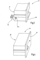
- FIG. 3 illustrates the socket insert 12 separately in a partial perspective view.
- an operating device connector 32 is arranged, which, for example, as a plug that fits the operating medium output 23.
- the operating medium connector 32 can have a number of electrical contacts that come into electrical contact with contacts of the operating medium output 23 when the socket insert 12 is completely pushed into the receiving compartment 21 and locked therein.
- the electrical contacts can be connected to contacts in the sockets 17, 18, 19 and/or to the pins 20. If other operating mediums, such as fluid and/or light and/or vacuum, are to be transmitted, the socket insert has corresponding connectors on its rear side 31 and on its front side 35.
- Figure 5 illustrates the rear side 31 of the socket insert 12 and the equipment connector 32 with its contacts K in a top view.
- the equipment connector 32 is spatially and functionally assigned to the equipment output 23.
- the surface 33 opposite the data connector 24, which in Figure 5 for illustrative purposes is outlined in dashed lines.
- the socket insert 12 in the sockets 17, 18, 19 and, if applicable, on the pins 20 provides the operating currents and/or signal currents required for connecting the instrument.
- the socket insert 12 covers the data connector 24 so that it remains inaccessible to the user of the device 10 and the user of the instrument.
- the device 10 therefore offers no possibility for the unauthorized and uninitiated operator to intentionally or inadvertently access the data connector 24 and thus the internal setting options of the device 10.
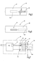
- the service technician has access to service call 34, as described in the Figures 4 and 6
- This has an outer contour that is adapted to the inner contour of the receiving compartment 21 or is at least designed in such a way that it is possible to insert the service insert 34 into the receiving compartment 21.
- the service insert 34 can have a length such that its front plate 35 is flush with the front side 13 of the device 10. Alternatively, the service insert 34 can also be designed to be longer so that it protrudes from the receiving compartment 12 after being inserted therein.
- the service insert 34 can, if required, be provided with locking means in order to lock it in the receiving compartment 21. Alternatively, such locking means can also be omitted.
- the service insert 34 has a data connector 37 (or another device that can be connected to the data interface of the device 10) on its rear side 36 facing away from the front panel 35, the shape and position of which is adapted to the data connector 24 of the receiving compartment 21.
- the data connector 37 can be designed as a multi-pole electrical connector that has a number of contacts that come into contact with contacts of the data connector 24, with the service insert 34 being inserted into the receiving compartment 21.
- the part 38 of the rear side 36 that is opposite the equipment outlet 23 is in Figure 6 shown delimited by a dashed line. This area, ie, this part 38 of the rear side 36 is free, ie, no elements are arranged there that could come into electrical contact with contacts of the equipment output 23.
- the service insert 24 can be designed as a passive element in that a socket 39 for connecting an electrical data processing device is provided on its front panel 35.
- the contacts of the socket 39 can be connected to corresponding contacts of the data connector 37.
- the socket 39 can be any socket, for example a USB socket, a network socket or the like.
- the socket insert 12 is designed for the connection of an instrument and is operational. If the device 10 is to be prepared for the operation of other instruments, this can be made possible by the maintenance technician by changing the socket insert 12 by replacing the socket insert 12 with another suitable socket insert.
- the maintenance technician wants to update the software of the device 10, parameterize the device 10 differently from the previous setting, read operating data or measured values from the device 10 or read in or out other data, he needs access to the service interface of the device 10.
- This is formed by the data connector 24.
- the service technician first removes the socket insert 12 from the device and now has access to the data connector 24. If this is (unlike in Figure 2 shown) as a network socket or as a USB socket, he can connect his laptop, notebook or other data processing device directly to this socket.
- a data connector 24 is provided in the device 10, which is not in standards of a network socket or a USB socket, making unauthorized access to the device software even more difficult.
- the service insert 34 is available to the service technician, which he then inserts into the storage compartment 12. Once this has been done, he can connect a cable to the front panel 35 or the socket 39 in order to establish a connection between his data processing device (laptop, notebook, etc.) and the control 40 of the device 10 (see Figure 7 ).
- the service technician After maintenance has been carried out, the service technician removes the service insert 34 from the receiving compartment 21 and inserts the socket insert 12 (or another socket insert if a change is desired) into the receiving compartment 21.
- Figure 7 schematically illustrates a device 10 with an electrical power unit 41 which feeds the operating medium output 23, for example with high-frequency alternating voltage, which is suitable for coagulating, ablating or cutting biological tissue.
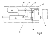
- Figure 8 a device 10, the control 40 of which additionally controls a fluid channel 42.
- This leads from a gas source 43, which can be designed as an external gas source or, as shown, within the device 10, via at least one valve 44 to the operating medium outlet 23.
- the operating medium outlet 23 here comprises a plug connector for fluids as well as plug connectors for the electrical voltage or current emitted by the power unit 41.
- Such a configuration can be used to power the socket insert 11 as shown in Figure 4 Again, the bushing insert 11 can be removed and replaced by the service insert 34 for maintenance purposes. which then provides the service technician with access to the controller 40.
- a socket insert 11 can also be provided that only transmits fluid media and/or other power or information-carrying media, such as light.
- the fluid channel 42 can also be designed as a suction channel.
- a service insert can be provided which itself contains a storage medium and/or at least one information processing element, such as a microcontroller.
- a service insert 34 can, for example, be set up to load data or programs into the controller 40 after the service insert 34 has been inserted into the receiving compartment 21.
- the front panel 35 can, for example, be designed without connection options and connection options for another computer.
- Such a service insert 34 can additionally or alternatively also be set up to read data from the controller 40 and store it in itself.
- Such a service call 34 can also involve the Figure 4 illustrated socket may be provided to connect an external device, such as a laptop or the like, in order to control, initiate or otherwise influence a data transfer from the service insert 34 to the controller 40 or from the controller 40 to the service insert 34.
- an external device such as a laptop or the like
- the service insert 34 can also contain a radio module, for example a Bluetooth module or a WLAN module, to establish a connection to an external data processing device, such as a mobile phone, a tablet, a notebook or a laptop, in order to enable communication between the controller 40 and the respective mobile terminal.
- a radio module for example a Bluetooth module or a WLAN module
- an external data processing device such as a mobile phone, a tablet, a notebook or a laptop
- the service insert 34 can contain storage means and/or data processing means.
- the device 10 has a socket insert 11 which is arranged in a receiving compartment 21 of the device 10.
- the socket insert 11 is connected to an equipment interface 34 of the device.
- a data interface 24 is also arranged in the receiving compartment 21, which is covered by the socket insert 11 and is therefore inaccessible from the outside.
- the socket insert 11 can be removed and replaced by a service insert 34, which on the one hand covers the equipment output 23 but contacts the data connector 24.
- the service insert 34 can communicate directly or an external device (laptop, notebook, tablet, etc.) can communicate with the device control 40 via the service insert 34 in order to read in or read out data and/or programs, update programs, change data, change device parameters or the like.
- the arrangement of the service interface covered by the socket insert 11, 12 represents an effective means of controlling access to the service interface. It makes it difficult or prevents unauthorized access to the interface and damage to people and material that would otherwise occur due to the lack of a puncture-proof potential separation between the service interface and in particular the power part of the device control.
Landscapes
- Engineering & Computer Science (AREA)
- Health & Medical Sciences (AREA)
- Business, Economics & Management (AREA)
- Theoretical Computer Science (AREA)
- Biomedical Technology (AREA)
- Physics & Mathematics (AREA)
- Human Resources & Organizations (AREA)
- Signal Processing (AREA)
- General Business, Economics & Management (AREA)
- General Physics & Mathematics (AREA)
- Computer Networks & Wireless Communication (AREA)
- Public Health (AREA)
- Medical Informatics (AREA)
- General Health & Medical Sciences (AREA)
- Surgery (AREA)
- Life Sciences & Earth Sciences (AREA)
- General Engineering & Computer Science (AREA)
- Entrepreneurship & Innovation (AREA)
- Computer Hardware Design (AREA)
- Tourism & Hospitality (AREA)
- Strategic Management (AREA)
- Epidemiology (AREA)
- Quality & Reliability (AREA)
- Operations Research (AREA)
- Primary Health Care (AREA)
- Marketing (AREA)
- Economics (AREA)
- Microelectronics & Electronic Packaging (AREA)
- Nuclear Medicine, Radiotherapy & Molecular Imaging (AREA)
- Otolaryngology (AREA)
- Plasma & Fusion (AREA)
- Heart & Thoracic Surgery (AREA)
- Molecular Biology (AREA)
- Animal Behavior & Ethology (AREA)
- Veterinary Medicine (AREA)
- Details Of Connecting Devices For Male And Female Coupling (AREA)
- Connector Housings Or Holding Contact Members (AREA)
- Measuring And Recording Apparatus For Diagnosis (AREA)
- Infusion, Injection, And Reservoir Apparatuses (AREA)
Description
- Die Erfindung betrifft ein Gerät mit Serviceschnittstelle und ein Verfahren zur Wartung des Geräts, insbesondere unter Sicherstellung einer Zugangskontrolle zu einer Serviceschnittstelle.
- Zum Betrieb von medizinischen Instrumenten, insbesondere Kryoinstrumenten, elektrochirurgischen Instrumenten und anderen, insbesondere bei der Operation am menschlichen und tierischen Patienten einzusetzenden Instrumenten, sind Geräte in Gebrauch, die zur Versorgung des betreffenden Instruments mit den benötigten Betriebsmittel eingerichtet sind.
- Aus der
US 2004/0214138 A1 ist ein Instrument zur Polymerisierung von polymerisierbarem Material bekannt, das beispielsweise im Rahmen von Zahnbehandlungen eingesetzt wird. Das Instrument arbeitet kabellos und enthält eine Lichtquelle, die über eine Batterie versorgt wird. Die Batterie ist über Ladekontakte mit einer Ladestation verbindbar, in welcher das Instrument bei Nichtgebrauch gelagert wird. Das Instrument enthält einen Mikrocontroller, der einerseits mit einem Programm-Wahlschalter verbunden ist und andererseits über eine Datenverbindung mit einem PC kommunizieren kann. Entsprechend sind an dem Instrument Datenübertragungskontakte vorhanden. - Weiter offenbart die
US 2015/0229083 A1 ein Gerät zur Versorgung von Instrumenten mit Betriebsmitteln. Dazu sind an der Frontseite des Gerätes entsprechende Steckbuchsen vorgesehen. - Bei dem Betriebsmittel kann es sich um ein stoffliches oder energetisches Mittel handeln. Betriebsmittel können Flüssigkeiten, Gase, Vakuum, elektrische Spannungen, elektrische Ströme, sichtbares oder unsichtbares Licht sein. Das Betriebsmittel kann Leistung und/oder Information tragen und transportieren. Beispiele für Betriebsmittel sind Flüssigkeiten oder Gase wie beispielsweise Wasser, NaCl-Lösung, Argon, Stickstoff, Kohlenstoffdioxyd, Sauerstoff, Aerosole oder dergleichen. Das Betriebsmittel kann dem Instrument zugeführt oder von diesem abgeführt werden (Vakuum), beispielsweise zur Rauchgasabsaugung. Das Betriebsmittel kann Licht, z.B. Laserlicht sein, das dem Instrument zugeführt wird, um eine Wirkung auf biologisches Gewebe auszuüben. Es kann sich auch um Licht zur Operationsfeldbeleuchtung handeln, das dem Instrument zugeführt wird. Auch kann von dem Instrument aufgenommenes Licht zu dem Gerät geleitet werden. Ist das Betriebsmittel elektrischer Strom, kann es sich um Gleichstrom, Wechselstrom, hochfrequenten Wechselstrom handeln, der beispielsweise zum Koagulieren, Thermofusionieren, Abladieren, Schneiden oder zur Bewirkung anderer Effekte dient. Das Gerät kann darauf eingerichtet sein, eins oder mehrere der genannten Betriebsmittel bereitzustellen und/oder aufzunehmen. Beides wird von dem Begriff der "Versorgung" umfasst.
- Solche Geräte sind aus dem Stand der Technik wie z. B. aus der oben genannten
US 2015/0229083 A1 prinzipiell bekannt. Weiter offenbart dazu dieEP 2 904 982 A1 ein Gerät mit einem allseits geschlossenen Gehäuse, das an seiner Front Aufnahmefächer für Buchseneinsätze aufweist. Jeder Buchseneinsatz schließt frontseitig mit der Gerätevorderseite bündig ab und bildet somit aus Sicht des Nutzers einen Teil der Frontfläche des Geräts. Der Buchseneinsatz enthält elektrische Anschlüsse (Buchsen) zum Anschluss eines chirurgischen Instruments. Der Buchseneinsatz ist in dem Aufnahmefach durch ein lösbares Verriegelungsmittel arretiert und an seiner von der Frontseite abgewandten Seite mit dem Gerät über eine Steckverbindung verbunden. - Solche Geräte enthalten normalerweise Steuerungen oder sonstige elektrische Schaltungen, die parametrierbar sind und/oder programmgesteuert sind und/oder im Betrieb Daten gewinnen und speichern und/oder auf Basis von abgespeicherten Daten arbeiten. Zu Service- und Wartungszwecken ist es erforderlich, Wartungstechnikern auf die elektrischen Schaltungen, d.h., deren Parameter und/oder Daten und/oder Programme Zugriff zu gewähren. Dazu ist typischerweise eine Serviceschnittstelle vorhanden, die jedoch elektrisch vom Leistungsteil des Geräts getrennt sein muss, um Schäden für Personen und Material auch bei unbedarftem Umgang auszuschließen.
- Davon ausgehend ist es Aufgabe der Erfindung, ein Gerät zur Versorgung von medizinischen Instrumenten zu schaffen, das eine Serviceschnittstelle aufweist, wobei jedoch mit einfachen Mitteln die Schädigung von Benutzern ausgeschlossen werden soll.
- Diese Aufgabe wird mit dem Gerät nach Anspruch 1 und/oder dem Verfahren nach Anspruch 13 gelöst. Bevorzugte Ausführungsformen sind in den abhängigen Ansprüchen definiert.
- Nach dem erfindungsgemäßen Konzept weist das erfindungsgemäße Gerät eine Serviceschnittstelle in Gestalt eines Datensteckverbinders auf, die bzw. der in dem Aufnahmefach des Buchseneinsatzes angeordnet ist, sodass die Serviceschnittstelle bei betriebsfertig bereitstehendem Gerät von dem Buchseneinsatz verdeckt und somit für den Bediener unzugänglich ist. Für den Wartungstechniker, der Zugang zu dem Datensteckverbinder und somit zur Gerätsteuerung benötigt, ist der Buchseneinsatz aus dem Aufnahmefach herausnehmbar. Typischerweise ist der Buchseneinsatz durch ein Verriegelungsmittel in dem Aufnahmefach gesichert. Das Verriegelungsmittel kann so gestaltet sein, dass es mittels eines Werkzeugs lösbar ist. Beispielsweise kann das Verriegelungsmittel einen Entriegelungsstift enthalten, der in einer von der Frontseite des Buchseneinsatzes zugänglichen Bohrung her axial bewegt werden kann, um dadurch das Verriegelungsmittel zu lösen.
- Nach Entnahme des Buchseneinsatzes aus dem Aufnahmefach ist die Serviceschnittstelle zugänglich, die beispielsweise als Datensteckverbinder (männlich oder weiblich) ausgebildet ist. Ist die Serviceschnittstelle beispielsweise ein genormter Steckverbinder, wie z.B. ein USB-Steckverbinder oder dergleichen, kann nun ein entsprechendes Kabel an diesen angeschlossen und somit die Verbindung zu einem externen Gerät, beispielsweise einem Laptop, hergestellt werden. Der Datensteckverbinder ist, wenn der Buchseneinsatz in dem Aufnahmefach angeordnet ist, von dem Buchseneinsatz verdeckt und vorzugsweise nicht mit diesem verbunden, sondern frei. Um dies sicherzustellen, kann der Buchseneinsatz oder jede andere Serviceschnittelle so ausgebildet sein, dass er keine mit dem Datensteckverbinder verbindbaren Anschlüsse aufweist.
- An der von der Frontseite abliegenden Begrenzungswand des Aufnahmefachs, d.h., an dessen Rückseite, sind der Betriebsmittelausgang und die Serviceschnittstelle z.B. in Form des Datensteckverbinders angeordnet. Der Betriebsmittelausgang und der Datensteckverbinder sind vorzugsweise zueinander in einem seitlichen Abstand angeordnet, der eine sichere elektrische Isolation zwischen dem Betriebsmittelausgang und dem Datensteckverbinder ermöglicht. Der Datensteckverbinder und der Betriebsmittelausgang sind somit räumlich getrennt. Durch die räumliche Trennung und durch die Abdeckung durch den Buchseneinsatz kann auf elektrische Potentialtrennungsmaßnahmen für den Datensteckverbinder verzichtet werden. Dies senkt den konstruktiven Aufwand und den Platzbedarf, der sonst für eine sichere hochspannungsfeste Trennstrecke in der von dem Datensteckverbinder weg führenden Datenleitung vorgesehen werden müsste.
- Typischerweise ist dem Gerät ein Serviceeinsatz zugeordnet, der vom Servicetechniker bereitgehalten und mitgeführt werden kann. Der Serviceeinsatz weist eine Außenkontur auf, die ein Einführen des Serviceeinsatzes in das Aufnahmefach ermöglicht. Der Serviceeinsatz weist ein Gehäuse auf, das an einer Endfläche ein zur Serviceschnittstelle passendes Gegenstück, z.B. einen Datensteckverbinder (weiblich oder männlich) aufweist, der an den Datensteckverbinder des Geräts angepasst ist. Der Datensteckverbinder ist dabei an einer solchen Stelle der Endfläche angeordnet, dass er beim Einführen in das Aufnahmefach mit dem Datensteckverbinder des Geräts in Eingriff kommt und eine korrekte elektrische Verbindung hergestellt ist.
- Der Servicesteckverbinder weist typischerweise keinen Anschluss für den Betriebsmittelausgang des Geräts auf, sodass der Serviceeinsatz mit dem Betriebsmittelausgang des Geräts unverbunden ist, und zwar auch dann, wenn der Serviceeinsatz in das Aufnahmefach eingesetzt ist.
- Der Serviceeinsatz kann rein passiv ausgebildet sein, indem er an einem in Benutzung aus dem Aufnahmefach herausschauenden Abschnitt seines Gehäuses oder schlicht an seiner Vorderseite eine Steckbuchse, z.B., eine USB-Buchse aufweist. Andere Steckbuchsen wie z.B. zwei- oder mehrpolige Steckbuchsen, Netzwerkbuchsen oder dergleichen können zusätzlich oder alternativ vorgesehen sein. Eine oder mehrere solcher Steckbuchsen bilden eine Kommunikationsschnittstelle, an die ein andere datenverarbeitendes Gerät, d.h. ein Computer, ein Laptop, ein Notebook, ein Tablet, ein Smartphone oder dergleichen angeschlossen werden kann.
- Alternativ kann die Schnittstelle zur Kommunikation mit einem anderen Computer als auch Netzwerkschnittstelle oder als Funkverbindung ausgebildet sein. Dazu kann der Serviceeinsatz ein Funkmodul, z.B. ein Bluetooth-Modul oder ein WLAN-Modul enthalten, das zur Kommunikation mit entsprechenden Gegenstellen z.B. in Gestalt eines Computers, eines Laptops, eines Notebooks, eines Tablets, eines Smartphones oder dergleichen eingerichtet ist.
- Ergänzend oder alternativ ist es möglich, dass der Serviceeinsatz eigene Speichermittel und/oder eigene Datenverarbeitungsmittel enthält, die durch manuelle Bedienmittel oder über eine Kommunikationsschnittstelle von einem anderen elektronischen Gerät wie z.B. einem mobilen Endgerät (Mobiltelefon, Tablet, Laptop, Notebook, usw.) bedienbar oder aktivierbar ist. Das Speichermittel kann darauf ausgelegt sein, direkt oder über Vermittlung eines in dem Serviceeinsatz untergebrachten Computers Daten oder Programme mit der Steuerung des Geräts auszutauschen.
- Das bevorzugte Verfahren zur Wartung eines Geräts umfasst die Entnahme des Buchseneinsatzes aus dem Aufnahmefach, das Einsetzen des Serviceeinsatzes in das Aufnahmefach, die Aktivierung des Serviceeinsatzes, die Entnahme des Serviceeinsatzes aus dem Aufnahmefach und das Wiedereinsetzen des Buchseinsatzes in das Aufnahmefach.
- Das Einsetzen des Serviceeinsatzes in das Aufnahmefach umfasst die Kopplung der Datensteckverbinder des Geräts und des Serviceeinsatzes. Das Aktivieren des Serviceeinsatzes umfasst das Freigeben des Datenaustausches zwischen dem Serviceeinsatz und der Gerätesteuerung oder des Datenaustausches zwischen einem an den Serviceeinsatz angeschlossenen datenverarbeitenden Geräts (Computer, Laptop, Notebook, Tablet, Smartphone) und der Gerätesteuerung über den Serviceeinsatz. Es ist möglich, dass der Datenaustausch lediglich das Übertragen von Daten von dem Serviceeinsatz auf die Gerätesteuerung beinhaltet. Es ist auch möglich, dass der Datenaustausch lediglich das Übertragen von Daten von der Gerätesteuerung auf den Serviceeinsatz beinhaltet. Es ist weiterhin auch möglich, dass der Datenaustausch die Datenübertragung in beiden vorgenannten Richtungen umfasst.
- Die ausgetauschten Daten können auch oder ausschließlich Anwenderprogramme sein. Die ausgetauschten Daten können Betriebsdaten oder Betriebsparameter des Geräts oder auch vom Gerät gesammelte Messwerte sein, die auf einem Speicher des Geräts oder einem Speicher gehalten werden, der in dem Serviceeinsatz vorgesehen ist. Ergänzend oder alternativ können die Daten über die oben erwähnte Datenschnittstelle an ein externes Gerät, wie beispielsweise ein dem Servicetechniker zur Verfügung stehendes Computergerät wie beispielsweise ein Mobiltelefon, ein Tablet, ein Laptop, ein Notebook oder dergleichen übertragen werden.
- Einzelheiten eines exemplarischen Ausführungsbeispiels der Erfindung sind der Zeichnung, den Unteransprüchen oder der zur Zeichnung gehörigen Beschreibung zu entnehmen. Es zeigen:
-
Figur 1 ein erfindungsgemäßes Gerät in ausschnittsweiser vereinfachter Perspektivdarstellung mit Blickrichtung auf seine Frontseite, -
Figur 2 das Gerät nachFigur 1 mit herausgenommenen Buchseneinsatz, in Perspektivdarstellung, -
Figur 3 den Buchseneinsatz für das Gerät nachFigur 1 und 2 , in perspektivischer Darstellung, -
Figur 4 einen Serviceeinsatz für das Gerät nachFigur 1 und 2 , -
Figur 5 den Buchseneinsatz nachFigur 3 , in Rückansicht, -
Figur 6 den Serviceeinsatz nachFigur 4 , in Rückansicht, -
Figur 7 das Gerät nachFigur 1 und 2 in schematischer Blockdarstellung, -
Figur 8 eine alternative Ausführungsform des erfindungsgemäßen Geräts in schematischer Blockdarstellung. - In
Figur 1 ist ein Gerät 10 veranschaulicht, das zur Speisung eines oder mehrerer nicht dargestellter Instrumente dient. Das exemplarisch veranschaulichte Gerät 10 dient z.B. zur Versorgung des jeweiligen medizinischen Instruments mit Betriebsmitteln wie beispielsweise fluiden Medien, das heißt zum Beispiel Gasen, Aerosolen und/oder Flüssigkeiten. Der Begriff der "Versorgung" umfasst auch die Aufnahme von Medien aus dem Instrument, das heißt die Bereitstellung von Vakuum oder Absaugleistung zu Absaugzwecken. Das Gerät kann alternativ oder zusätzlich zur Versorgung von einem oder mehreren medizinischen Instrumenten mit elektrischem Strom eingerichtet sein. Zusätzlich oder alternativ kann das Gerät 10 zur Versorgung des medizinischen Instruments mit Licht oder auch zur Aufnahme von Licht eingerichtet sein, das von dem Instrument aufgenommen oder erzeugt worden ist. Auch dies soll unter dem Begriff der "Bereitstellung von Betriebsmitteln" verstanden werden. - Zur Bereitstellung von mindestens einem Betriebsmittel können an dem Gerät 10 ein oder mehrere Anschlussmöglichkeiten für medizinische Instrumente vorgesehen sein. Bei dem in
Figur 1 exemplarisch veranschaulichten Gerät sind zwei Anschlussmöglichkeiten gegeben, die durch Buchseneinsätze 11, 12 gegeben sind. Diese Buchseneinsätze 11, 12 sind an der Frontseite 13 des Gerät 10 angeordnet. Die Buchseneinsätze 11, 12 sind vorzugsweise so ausgebildet, dass sie zum Betrieb eines Instruments erforderliche Anschlüsse enthalten. Beispielsweise weist der Buchseneinsatz 11 eine Steckbuchse 14 für ein Fluid und/oder weitere Steckbuchsen 15, 16 für elektrischen Strom auf. Die Steckbuchsen 15, 16 können Betriebsstrom, steuernden Strom um zum Beispiel das Gerät 10 von dem angeschlossenen Instrument auszusteuern oder Behandlungsströme, Messströme und dergleichen führen. Das Gerät kann (muss aber nicht) zusätzliche Anschlüsse enthalten, z.B. einen oder mehrere Anschlüsse für eine Neutralelektrode. - Der Buchseneinsatz 12 ist exemplarisch als rein elektrische Buchse veranschaulicht, die mehrere Steckbuchsen 17, 18, 19 für den Behandlungsstrom eines anzuschließenden Instruments aufweist. Außerdem können an dem Buchseneinsatz 12 ein oder mehrere Pins 20 vorgesehen sein, die zur Erfassung des Typs des eingesteckten Steckers dienen können und die axial fest oder axial beweglich angeordnet sein können. Weiter können ein oder mehrere Anschlüsse vorgesehen sein, die zu Steuerleitungen gehören und über die am Instrument vorgesehene Bedienelemente mit der Gerätesteuerung verbindbar sind.
- Die Buchseneinsätze 11, 12 sind lediglich exemplarischer Natur. Es kann auch ein Buchseneinsatz vorgesehen werden, der ausschließlich ein oder mehrere Fluidbuchsen umfasst. Es kann ein Buchseneinsatz vorgesehen sein, der ausschließlich ein oder mehrere Anschlüssen für Licht aufweist, um Licht zu dem Instrument zuleiten oder von diesem aufzunehmen. Außerdem kann ein Buchseneinsatz vorgesehen sein, der ausschließlich ein oder mehrere Anschlüsse aufweist, an denen eine Absaugfunktion (Vakuum) bereitgestellt wird. Es kann ein Buchseneinsatz vorgesehen sein, der mindestens einen Anschluss für Behandlungsstrom, Signalstrom oder sonstige Träger von Energie und/oder Information aufweist. Es ist auch möglich, einen Buchseneinsatz vorzusehen, der zwei oder mehrere der vorgenannten verschiedenartigen Anschlüsse aufweist.
- Jeder Buchseneinsatz 11, 12 ist in einem Aufnahmefach angeordnet.
Figur 2 veranschaulicht dazu exemplarisch ein Aufnahmefach 21. Das Aufnahmefach 21 weist an seiner Rückwand 22 einen Betriebsmittelausgang 23 und eine Datenschnittstelle z.B. in Gestalt eines Datensteckverbinders 24 auf. Der Betriebsmittelausgang 23 und der Datensteckverbinder 24 sind dabei in seitlichem Abstand A zueinander angeordnet, der eine elektrische Isolation zwischen dem Betriebsmittelausgang 23 und dem Datensteckverbinder 24 und somit die nötigen Luft- und Kriechstrecken erbringt. - Der Betriebsmittelausgang 23 ist als elektrischer Steckverbinder mit vielen Kontakten dargestellt, wobei jedoch der Betriebsmittelausgang nicht auf derartige Steckverbinder beschränkt verstanden werden darf. Der Betriebsmittelausgang 23 kann durch jedes Verbindungsmittel gebildet werden, das zur sicheren Übertragung des jeweiligen Betriebsmittels von dem Gerät 10 auf den Buchseneinsatz 12 (oder 11) geeignet ist. Gleiches gilt für den Datensteckverbinder 24. Auch dieser ist in
Figur 2 als vielpolige Steckbuchse dargestellt. Es kann sich bei dem Datensteckverbinder 24 jedoch auch in jedem anderen zur Datenübertragung geeigneten Verbinder handeln. - In dem Aufnahmefach 21 können, falls gewünscht, Führungen 25, 26 für den Buchseneinsatz 12 und/oder zu einer Verriegelungseinrichtung gehörende Rastvorsprünge 27 oder sonstige Rastmittel angeordnet sein, um den Buchseneinsatz 11 oder 12 zum Beispiel in der in der
EP 2904982 A1 dargestellten Art zu verriegeln. Entsprechende Lösestifte 28, 29 zum Lösen einer entsprechenden Verriegelung können in den Buchseneinsätzen 11, 12 vorgesehen und von der Frontseite her zugänglich sein. -
Figur 3 veranschaulicht den Buchseinsatz 12 gesondert in ausschnittsweiser perspektivischer Darstellung. An seiner von der Frontseite 30 abliegenden Rückseite 31 ist ein Betriebsmittelverbinder 32 angeordnet, der zum Beispiel als zu dem Betriebsmittelausgang 23 passender Stecker ausgeführt ist. Der Betriebsmittelverbinder 32 kann eine Anzahl von elektrischen Kontakten aufweisen, die mit Kontakten des Betriebsmittelausgangs 23 in elektrische Führung geraten, wenn der Buchseneinsatz 12 in das Aufnahmefach 21 vollständig eingeschoben und darin verriegelt ist. Die elektrischen Kontakte können mit Kontakten in den Steckbuchsen 17, 18, 19 und/oder mit den Pins 20 verbunden sein. Sollen sonstige Betriebsmittel, wie z.B. Fluid und/oder Licht und/oder Vakuum übertragen werden, hat der Buchseneinsatz an seiner Rückseite 31 und an seiner Frontseite 35 entsprechende Verbinder. -
Figur 5 veranschaulicht die Rückseite 31 des Buchseneinsatzes 12 und den Betriebsmittelverbinder 32 mit seinen Kontakten K in Draufsicht. Wie ersichtlich, ist der Betriebsmittelverbinder 32 räumlich und funktional dem Betriebsmittelausgang 23 zugeordnet. Hingegen ist die dem Datensteckverbinder 24 gegenüberliegende Fläche 33, die inFigur 5 zur Veranschaulichung gestrichelt umgrenzt ist, frei. - Im Betrieb stellt der Buchseneinsatz 12 in den Steckbuchsen 17, 18, 19 sowie gegebenenfalls an den Pins 20 die für den Anschluss des Instruments erforderlichen Betriebsströme und/oder Signalströme bereit. Jedoch verdeckt der Buchseneinsatz 12 den Datensteckverbinder 24, so dass dieser für den Benutzer des Geräts 10 und den Benutzer des Instruments unzugänglich bleibt. Das Gerät 10 bietet somit für den nicht autorisierten und nicht eingeweihten Bediener keine Möglichkeit, absichtlich oder unbeabsichtigter Weise an den Datensteckverbinder 24 und somit an interne Einstellungsmöglichkeiten des Geräts 10 zu gelangen.
- Dem Servicetechniker steht der Serviceeinsatz 34 zur Verfügung, wie er in den
Figuren 4 und6 veranschaulicht ist. Dieser weist eine Außenkontur auf, die an die Innenkontur des Aufnahmefachs 21 angepasst ist oder zumindest so ausgebildet ist, dass ein Einführen des Serviceeinsatzes 34 in das Aufnahmefach 21 möglich ist. Der Serviceeinsatz 34 kann dabei eine solche Länge aufweisen, dass er mit seiner Frontplatte 35 bündig mit der Frontseite 13 des Geräts 10 abschließt. Alternativ kann der Serviceeinsatz 34 jedoch auch länger ausgebildet sein, sodass er nach dem Einsetzen in das Aufnahmefach 12 aus diesem herausragt. Der Serviceeinsatz 34 kann bedarfsweise mit Verriegelungsmitteln versehen sein, um ihn in dem Aufnahmefach 21 zu arretieren. Alternativ können solche Arretierungsmittel auch fehlen. - Der Serviceeinsatz 34 weist an seiner an der Frontplatte 35 wegweisenden Rückseite 36 einen Datensteckverbinder 37 (oder eine sonstige mit der Datenschnittstelle des Geräts 10 in Verbindung bringbare Einrichtung) auf, dessen Form und Position an den Datensteckverbinder 24 des Aufnahmefachs 21 angepasst ist. Der Datensteckverbinder 37 kann als mehrpoliger elektrischer Steckverbinder ausgebildet sein, der eine Anzahl von Kontakten aufweist, die mit Kontakten des Datensteckverbinders 24 in Kontakt kommen, wobei der Serviceeinsatz 34 in das Aufnahmefach 21 eingesetzt ist. Der dem Betriebsmittelausgang 23 dabei gegenüber liegende Teil 38 der Rückseite 36 ist in
Figur 6 durch eine gestrichelte Linie umgrenzt dargestellt. Diese Fläche, d.h., dieser Teil 38 der Rückseite 36 ist frei, d.h., dort sind keine Elemente angeordnet, die mit Kontakten des Betriebsmittelausgangs 23 in elektrischen Kontakt kommen könnten. - Der Serviceeinsatz 24 kann im einfachsten Fall als passives Element ausgebildet sein, indem an seiner Frontplatte 35 eine Steckbuchse 39 zum Anschluss eines elektrischen datenverarbeitenden Geräts vorgesehen ist. Die Kontakte der Steckbuchse 39 können mit entsprechenden Kontakten des Datensteckverbinders 37 verbunden sein. Die Steckbuchse 39 kann eine beliebige Steckbuchse, zum Beispiel eine USB-Buchse, eine Netzwerkbuchse oder dergleichen sein.
- Die Benutzung und Wartung des Geräts 10 ist wie folgt:
Bei normalem Betrieb ist der Buchseneinsatz 12 für den Anschluss eines Instruments vorgesehen und betriebsfähig. Soll das Gerät 10 zum Betrieb anderweitiger Instrumente hergerichtet werden, kann dies vom Wartungstechniker durch Wechsel des Buchseneinsatzes 12 ermöglicht werden, indem dieser den Buchseneinsatz 12 durch einen anderen geeigneten Buchseneinsatz austauscht. - Will der Wartungstechniker hingegen die Software des Geräts 10 aktualisieren, das Gerät 10 abweichend von der bisherigen Einstellung parametrieren, Betriebsdaten oder Messwerte aus dem Gerät 10 auslesen oder sonstige Daten ein- oder auslesen, benötigt er Zugang zur Serviceschnittstelle des Geräts 10. Diese wird durch den Datensteckverbinder 24 gebildet. Zu diesem Zweck entnimmt der Servicetechniker dem Gerät zunächst den Buchseneinsatz 12 und hat nun Zugang zu dem Datensteckverbinder 24. Ist dieser (anders als in
Figur 2 dargestellt) als Netzwerkbuchse oder als USB-Buchse ausgebildet kann er seinen Laptop, sein Notebook oder ein anderes Datenverarbeitendes Gerät direkt an diese Buchse anschließen. Bevorzugt wird aber in dem Gerät 10 ein Datensteckverbinder 24 vorgesehen, der nicht in Normen einer Netzwerksteckdose oder einer USB-Steckdose entspricht, sodass ein unbefugter Zugriff auf die Gerätesoftware weiter erschwert wird. Dem Servicetechniker steht jedoch der Serviceeinsatz 34 zur Verfügung, den er nun in das Aufnahmefach 12 einsetzt. Ist dies geschehen, kann er an der Frontplatte 35 bzw. der Steckbuchse 39 ein Kabel anschließen, um eine Verbindung zwischen seinem datenverarbeitenden Gerät (Laptop, Notebook, usw.) und der Steuerung 40 des Geräts 10 herstellen (sieheFigur 7 ). - Nach durchgeführter Wartung entfernt der Servicetechniker den Serviceeinsatz 34 aus dem Aufnahmefach 21 und setzt den Buchseneinsatz 12 (oder falls ein Wechsel gewünscht ist einen anderen Buchseneinsatz) in das Aufnahmefach 21 ein.
- Während
Figur 7 schematisch ein Gerät 10 mit einem elektrischen Leistungsteil 41 veranschaulicht, der den Betriebsmittelausgang 23, beispielsweise mit hochfrequenter Wechselspannung speist, die zum Koagulieren, Abladieren oder Schneiden vom biologischem Gewebe geeignet ist, zeigtFigur 8 ein Gerät 10, dessen Steuerung 40 zusätzlich dazu einen Fluidkanal 42 kontrolliert. Dieser führt von einer Gasquelle 43, die als externe Gasquelle oder auch wie dargestellt innerhalb des Geräts 10 ausgebildet sein kann, über mindestens ein Ventil 44 zu dem Betriebsmittelausgang 23. Der Betriebsmittelausgang 23 umfasst hier einen Steckverbinder für Fluide sowie Steckverbinder für die elektrische von dem Leistungsteil 41 abgegebene Spannung bzw. den Strom. - Eine solche Konfiguration kann zur Speisung des Buchseneinsatzes 11 dienen wie er in
Figur 4 veranschaulicht ist. Wiederum kann der Buchseneinsatz 11 entnommen und zu Wartungszwecken durch den Serviceeinsatz 34 ersetzt werden, der dann den Servicetechniker Zugang zu der Steuerung 40 bietet. - Anstelle eines Buchseneinsatzes 11, der sowohl fluide Medien als auch Strom überträgt, kann auch ein Buchseneinsatz 11 vorgesehen sein, der nur fluide Medien und/oder andere Leistungs- oder Informationstragende Medien, wie zum Beispiel Licht überträgt. Auch kann der Fluidkanal 42 als Absaugkanal ausgebildet sein.
- Bei allen vorstehend beschriebenen Ausführungsformen kann anstelle eines passiven Serviceeinsatzes 34, wie er in
Figur 4 dargestellt ist, ein Serviceeinsatz vorgesehen sein, der selbst ein Speichermedium und/oder wenigstens eine informationsverarbeitendes Element, wie beispielsweise einen Mikrocontroller enthält. Ein solcher Serviceeinsatz 34 kann beispielsweise darauf eingerichtet sein, Daten oder Programme in die Steuerung 40 einzuspielen, nachdem der Serviceeinsatz 34 in das Aufnahmefach 21 eingesetzt ist. In diesem Fall kann die Frontplatte 35 zum Beispiel ohne Verbindungsmöglichkeiten und Anschlussmöglichkeiten für einen weiteren Rechner ausgebildet sein. Ein solcher Serviceeinsatz 34 kann zusätzlich oder alternativ auch darauf eingerichtet sein, Daten aus der Steuerung 40 auszulesen und in sich abzuspeichern. - An einem solchen Serviceeinsatz 34 kann auch die in
Figur 4 veranschaulichte Steckbuchse vorgesehen sein, um ein externes Gerät, wie beispielsweise einen Laptop oder dergleichen, anzuschließen, um eine Datenübertragung von dem Serviceeinsatz 34 auf die Steuerung 40 oder von der Steuerung 40 auf den Serviceeinsatz 34 zu kontrollieren, zu initiieren oder auf sonstige Weise zu beeinflussen. - Der Serviceeinsatz 34 kann auch ein Funkmodul, beispielsweise ein Bluetoothmodul oder ein WLAN-Modul enthalten, um eine Verbindung zu einem externen datenverarbeitenden Gerät, wie beispielsweise einem Mobiltelefon, einem Tablet, einem Notebook oder einem Laptop herzustellen, um somit eine Kommunikation zwischen der Steuerung 40 und dem jeweiligen mobilen Endgerät zu ermöglichen. Dabei kann der Serviceeinsatz 34 zusätzlich zu dem Funkmodul Speichermittel und/oder datenverarbeitende Mittel enthalten.
- Das erfindungsgemäße Gerät 10 weist einen Buchseneinsatz 11 auf, der in einem Aufnahmefach 21 des Geräts 10 angeordnet ist. Der Buchseneinsatz 11 ist dabei an eine Betriebsmittelschnittstelle 34 des Geräts angeschlossen. In dem Aufnahmefach 21 ist zusätzlich eine Datenschnittstelle 24 angeordnet, die von dem Buchseneinsatz 11 verdeckt und damit von außen unzugänglich ist.
- Um Zugriff auf die Gerätesoftware und/oder Gerätedaten zu erhalten, kann der Buchseneinsatz 11 entfernt und durch einen Serviceeinsatz 34 ersetzt werden, der einerseits den Betriebsmittelausgang 23 verdeckt dafür aber den Datensteckverbinder 24 kontaktiert. In diesem Zustand kann der Serviceeinsatz 34 direkt oder ein externes Gerät (Laptop, Notebook, Tablet, usw.) vermittels des Serviceeinsatzes 34 mit der Gerätesteuerung 40 kommunizieren, um Daten und/oder Programme ein- oder auszulesen sowie Programme zu aktualisieren, Daten zu ändern, um Geräteparameter zu ändern oder dergleichen. Die durch den Buchseneinsatz 11, 12 verdeckte Anordnung der Serviceschnittstelle stellt ein wirksames Mittel zur Zugangskontrolle zu der Serviceschnittstelle dar. Es erschwert oder verhindert unbefugten Zugriff auf die Schnittstelle und Schäden für Personen und Material, die sonst auf Grund der fehlenden durchschlagsicheren Potentialtrennung zwischen der Serviceschnittstelle und insbesondere dem Leistungsteil der Gerätesteuerung auftreten könnten.
-
- 10
- Gerät
- 11
- Buchseneinsatz
- 12
- Buchseneinsatz
- 13
- Frontseite
- 14
- Steckbuchse für Fluid oder für bipolaren Koaxialstecker - je nach Ausführungsform
- 15 - 19
- Steckbuchsen für elektrischen Strom
- 20
- Pins
- 21
- Aufnahmefach
- 22
- Rückseite
- 23
- Betriebsmittelausgang
- 24
- Datensteckverbinder
- A
- Abstand
- 25, 26
- Führungen
- 27
- Rastvorsprung - Verriegelungsvorrichtung 27a
- 28, 29
- Lösestifte
- 30
- Frontseite
- 31
- Rückseite
- 32
- Betriebsmittelverbinder
- K
- Kontakte
- 33
- freie Fläche
- 34
- Serviceeinsatz
- 35
- Frontplatte
- 36
- Rückseite
- 37
- Datensteckverbinder
- 38
- Bereich/Fläche
- 39
- Steckbuchse
- 40
- Steuerung
- 41
- Leistungsteil
- 42
- Fluidkanal
- 43
- Gasquelle
- 44
- Ventil
Claims (13)
- Gerät (10), insbesondere zur Versorgung von medizinischen Instrumenten mit Betriebsmittel, insbesondere einem oder mehreren fluiden Medien und/oder elektrischem Strom,mit einem Gehäuse, in dem eine elektrische Schaltung (40) angeordnet ist, die mindestens einen Betriebsmittelausgang (23) aufweist oder mit einem solchen steuernd verbunden ist und die mindestens einen Datensteckverbinder (24) aufweist,mit einem Aufnahmefach (21), in dem der Betriebsmittelausgang (23) und der Datensteckverbinder (24) angeordnet sind,mit einem Buchseneinsatz (11, 12), der den Datensteckverbinder (24) abdeckend in dem Aufnahmefach (21) angeordnet ist und der geräteseitig einen Betriebsmittelverbinder (32) aufweist, der mit dem Betriebsmittelausgang (23) lösbar verbunden ist und der einen von außen her zugänglichen Instrumentenanschluss (14 - 19) aufweist, der mit dem Betriebsmittelverbinder (32) verbunden ist, wobei der Buchseneinsatz (11, 12) mit dem Datensteckverbinder (24) unverbunden ist und keine mit dem Datensteckverbinder (24) verbindbaren Anschlüsse aufweist.
- Gerät nach Anspruch 1, wobei der Datensteckverbinder (24) und
der Betriebsmittelausgang (23) in einem Abstand zueinander in dem Aufnahmefach (21) angeordnet sind. - Gerät nach einem der vorstehenden Ansprüche, wobei dem Buchseneinsatz (11, 12) eine Verriegelungsvorrichtung (27a) zur Arretierung des Buchseneinsatzes (11, 12) in dem Aufnahmefach (21) zugeordnet ist.
- Gerät nach einem der vorstehenden Ansprüche, wobei der Buchseneinsatz (11, 12) eine dem Aufnahmefach (21) angepasste Kontur aufweist.
- Gerät (10) nach einem der vorstehenden Ansprüche, mit einem Serviceeinsatz (34), der Gehäuse umfasst, das an einer Endfläche (36) einen Datensteckverbinder (37) aufweist, der an den Datensteckverbinder (24) des Geräts (10) angepasst ist.
- Gerät nach Anspruch 5, wobei der Serviceeinsatz (34) eine an das Aufnahmefach (21) angepasste Kontur aufweist.
- Gerät nach einem der Ansprüche 5 oder 6 , wobei der Serviceeinsatz (34) frei von Anschlussmitteln für den Betriebsmittelausgang (23) ist.
- Gerät nach einem der Ansprüche 5 bis 7, wobei der Serviceeinsatz (34) ein Speichermedium (34a) aufweist, das mit dem Datensteckverbinder (37) verbunden ist.
- Gerät nach einem der Ansprüche 5 bis 8, wobei der Serviceeinsatz (34) eine Schnittstelle (39) zur Kommunikation mit einem Computer aufweist.
- Gerät nach Anspruch 9, wobei die Schnittstelle (39) eine USB-Schnittstelle ist.
- Gerät nach Anspruch 9, wobei die Schnittstelle (39) eine Netzwerkschnittstelle ist.
- Gerät nach Anspruch 9, wobei die Schnittstelle eine Funkverbindung ist.
- Verfahren zur Wartung eines Geräts nach einem der Ansprüche 5 bis 12 mit folgenden Schritten:Entnahme des den Datensteckverbinder (24) nicht kontaktierenden Buchseneinsatzes (11, 12) aus dem Aufnahmefach (21),Einsetzen des den Datensteckverbinder (24) kontaktierenden Serviceeinsatzes (34) in das Aufnahmefach (21), Aktivierung des Serviceeinsatzes (34),Entnahme des den Datensteckverbinder (24) kontaktierenden Serviceeinsatzes (34) aus dem Aufnahmefach (21),Einsetzen des den Datensteckverbinder (24) nicht kontaktierenden Buchseneinsatzes (11, 12) in das Aufnahmefach (21).
Priority Applications (8)
| Application Number | Priority Date | Filing Date | Title |
|---|---|---|---|
| PL19182969.6T PL3758157T3 (pl) | 2019-06-27 | 2019-06-27 | Urządzenie z interfejsem serwisowym i sposób konserwacji urządzenia |
| EP19182969.6A EP3758157B1 (de) | 2019-06-27 | 2019-06-27 | Gerät mit serviceschnittstelle und verfahren zur wartung des geräts |
| BR102020011938-9A BR102020011938B1 (pt) | 2019-06-27 | 2020-06-15 | Aparelho e inserto de serviço para um aparelho |
| RU2020120053A RU2812213C2 (ru) | 2019-06-27 | 2020-06-17 | Прибор с сервисным интерфейсом и способ технического обслуживания прибора |
| KR1020200075810A KR102778574B1 (ko) | 2019-06-27 | 2020-06-22 | 서비스 인터페이스를 갖는 장치 및 상기 장치를 서비스하기 위한 방법 |
| JP2020109155A JP7398342B2 (ja) | 2019-06-27 | 2020-06-24 | サービスインターフェースを備えた装置およびその装置を保守点検するための方法 |
| CN202010587537.8A CN112152007B (zh) | 2019-06-27 | 2020-06-24 | 带有维修接口的设备和用于维修设备的方法 |
| US16/913,794 US11736414B2 (en) | 2019-06-27 | 2020-06-26 | Apparatus with service interface and method for servicing the apparatus |
Applications Claiming Priority (1)
| Application Number | Priority Date | Filing Date | Title |
|---|---|---|---|
| EP19182969.6A EP3758157B1 (de) | 2019-06-27 | 2019-06-27 | Gerät mit serviceschnittstelle und verfahren zur wartung des geräts |
Publications (3)
| Publication Number | Publication Date |
|---|---|
| EP3758157A1 EP3758157A1 (de) | 2020-12-30 |
| EP3758157C0 EP3758157C0 (de) | 2024-12-25 |
| EP3758157B1 true EP3758157B1 (de) | 2024-12-25 |
Family
ID=67296945
Family Applications (1)
| Application Number | Title | Priority Date | Filing Date |
|---|---|---|---|
| EP19182969.6A Active EP3758157B1 (de) | 2019-06-27 | 2019-06-27 | Gerät mit serviceschnittstelle und verfahren zur wartung des geräts |
Country Status (6)
| Country | Link |
|---|---|
| US (1) | US11736414B2 (de) |
| EP (1) | EP3758157B1 (de) |
| JP (1) | JP7398342B2 (de) |
| KR (1) | KR102778574B1 (de) |
| CN (1) | CN112152007B (de) |
| PL (1) | PL3758157T3 (de) |
Families Citing this family (3)
| Publication number | Priority date | Publication date | Assignee | Title |
|---|---|---|---|---|
| CN115768853B (zh) | 2020-08-06 | 2024-06-14 | 日亚化学工业株式会社 | 氮化物荧光体及其制造方法 |
| DE102022125312B3 (de) | 2022-09-29 | 2024-02-08 | Olympus Winter & Ibe Gmbh | Elektrochirurgischer Generator mit Ausgangsbuchse für elektrochirurgisches Instrument |
| JP7779888B2 (ja) | 2022-09-29 | 2025-12-03 | オリンパス・ヴィンター・ウント・イベ・ゲゼルシャフト・ミット・ベシュレンクテル・ハフツング | 電気外科用機器のためのモジュラー出力ソケットを備えた電気外科用発電機 |
Citations (2)
| Publication number | Priority date | Publication date | Assignee | Title |
|---|---|---|---|---|
| US20040214138A1 (en) * | 2003-04-25 | 2004-10-28 | Ivoclar Vivadent Ag | Light polymerization device |
| US20150229083A1 (en) * | 2014-02-10 | 2015-08-13 | Erbe Elektromedizin Gmbh | Socket Insert For An Electrosurgical Device, Electrosurgical Device With A Socket Insert And Set With A Removal Tool |
Family Cites Families (27)
| Publication number | Priority date | Publication date | Assignee | Title |
|---|---|---|---|---|
| DE19855431A1 (de) * | 1998-11-30 | 2000-05-31 | Bosch Gmbh Robert | Steuergerät |
| RU2203008C2 (ru) | 2001-02-27 | 2003-04-27 | Нугуманов Айрат Азатович | Универсальный медицинский прибор для лечения лор-заболеваний |
| US20020172001A1 (en) * | 2001-05-17 | 2002-11-21 | Homer Steven S. | Modular input device system for a portable computing device |
| TW538585B (en) * | 2001-10-30 | 2003-06-21 | Primax Electronics Ltd | Power adapting device applied in portable electronic device |
| US7338443B1 (en) * | 2002-04-29 | 2008-03-04 | Tucker Peter L | Secure patient data recorder for recording monitored vital sign data |
| US7399205B2 (en) * | 2003-08-21 | 2008-07-15 | Hill-Rom Services, Inc. | Plug and receptacle having wired and wireless coupling |
| US20050063116A1 (en) * | 2003-09-24 | 2005-03-24 | Dave Rotheroe | Power cord with monitor circuit |
| IL160417A (en) * | 2004-02-16 | 2011-04-28 | Mosaid Technologies Inc | Unit added to the outlet |
| DE102004008833A1 (de) * | 2004-02-20 | 2005-09-08 | Trumpf Kreuzer Medizin Systeme Gmbh + Co. Kg | Steckdosenmodul für einen Stativkopf eines medizinischen Deckenstativs |
| JP4472416B2 (ja) | 2004-04-28 | 2010-06-02 | オリンパス株式会社 | 内視鏡接続用アダプタ装置 |
| US7108468B2 (en) * | 2004-11-01 | 2006-09-19 | Tekelec | Methods and systems for controlling shutdown and operation of a module within a slot in a shelf of a rack-based computing system |
| US7568619B2 (en) * | 2004-12-15 | 2009-08-04 | Alcon, Inc. | System and method for identifying and controlling ophthalmic surgical devices and components |
| EP1961083B1 (de) | 2005-11-23 | 2016-01-27 | Draeger Medical Systems, Inc. | Verbindersystem |
| US7657763B2 (en) * | 2005-12-29 | 2010-02-02 | Panasonic Electric Works Co., Ltd. | Systems and methods for selectively controlling electrical outlets using power profiling |
| US7865639B2 (en) * | 2007-01-04 | 2011-01-04 | Whirlpool Corporation | Appliance with an electrically adaptive adapter to alternatively couple multiple consumer electronic devices |
| DE102010000642B4 (de) | 2009-03-12 | 2015-05-07 | Erbe Elektromedizin Gmbh | Schaltsteuereinrichtung und Handhabungsteil eines medizinischen Instruments |
| US8225015B2 (en) * | 2009-06-15 | 2012-07-17 | General Electric Company | Systems, methods, and apparatus for medical device interface connectivity |
| US11871901B2 (en) | 2012-05-20 | 2024-01-16 | Cilag Gmbh International | Method for situational awareness for surgical network or surgical network connected device capable of adjusting function based on a sensed situation or usage |
| DE102013013299A1 (de) * | 2013-08-12 | 2015-02-12 | Endress + Hauser Conducta Gesellschaft für Mess- und Regeltechnik mbH + Co. KG | Verfahren zum Bedienen eines Feldgeräts |
| DE102014200533A1 (de) * | 2014-01-14 | 2015-07-16 | Olympus Winter & Ibe Gmbh | Wechseldatenträger, medizinisches Gerät und Verfahren zum Betrieb eines Wechseldatenträgers |
| US20160172808A1 (en) * | 2014-12-16 | 2016-06-16 | Leviton Manufacturing Co., Inc. | Combined audio/video and alternating current (ac) power module |
| AU2016304995B2 (en) * | 2015-08-13 | 2021-10-21 | Bayer Healthcare Llc | Systems for determining, and devices for indicating, viable life of replaceable components thereof and methods therefor |
| US10639059B2 (en) | 2015-11-25 | 2020-05-05 | Ethicon Llc | Restricted usage features for surgical instrument |
| EP3433626B1 (de) * | 2016-03-23 | 2023-05-03 | Eaton Intelligent Power Limited Corporation | Adapter für die prüfung einer elektrischen anlage |
| JP2017219907A (ja) | 2016-06-03 | 2017-12-14 | コニカミノルタ株式会社 | 情報読み出し治具及び電子機器 |
| US20210250553A1 (en) * | 2020-02-10 | 2021-08-12 | Jose Henry Naber, JR. | Vehicle mirror recording system |
| GB2595695A (en) * | 2020-06-03 | 2021-12-08 | Source To Site Accessories Ltd | Modular electrical accessory |
-
2019
- 2019-06-27 PL PL19182969.6T patent/PL3758157T3/pl unknown
- 2019-06-27 EP EP19182969.6A patent/EP3758157B1/de active Active
-
2020
- 2020-06-22 KR KR1020200075810A patent/KR102778574B1/ko active Active
- 2020-06-24 JP JP2020109155A patent/JP7398342B2/ja active Active
- 2020-06-24 CN CN202010587537.8A patent/CN112152007B/zh active Active
- 2020-06-26 US US16/913,794 patent/US11736414B2/en active Active
Patent Citations (2)
| Publication number | Priority date | Publication date | Assignee | Title |
|---|---|---|---|---|
| US20040214138A1 (en) * | 2003-04-25 | 2004-10-28 | Ivoclar Vivadent Ag | Light polymerization device |
| US20150229083A1 (en) * | 2014-02-10 | 2015-08-13 | Erbe Elektromedizin Gmbh | Socket Insert For An Electrosurgical Device, Electrosurgical Device With A Socket Insert And Set With A Removal Tool |
Also Published As
| Publication number | Publication date |
|---|---|
| KR20210001975A (ko) | 2021-01-06 |
| CN112152007B (zh) | 2022-09-27 |
| KR102778574B1 (ko) | 2025-03-12 |
| JP2021010728A (ja) | 2021-02-04 |
| BR102020011938A2 (pt) | 2021-01-05 |
| EP3758157A1 (de) | 2020-12-30 |
| CN112152007A (zh) | 2020-12-29 |
| RU2020120053A (ru) | 2021-12-20 |
| JP7398342B2 (ja) | 2023-12-14 |
| PL3758157T3 (pl) | 2025-03-17 |
| EP3758157C0 (de) | 2024-12-25 |
| US20200412668A1 (en) | 2020-12-31 |
| US11736414B2 (en) | 2023-08-22 |
Similar Documents
| Publication | Publication Date | Title |
|---|---|---|
| DE102012220256A1 (de) | Technologien zum Kofigurieren von Kontakten eines Steckverbinders | |
| EP3032366B1 (de) | Automatisierungsgerät und verfahren zum betreiben eines automatisierungsgeräts | |
| DE602004006116T2 (de) | Kodierte universelle stromausgangs- und stromversorgungsverbinder | |
| DE202012010672U1 (de) | Steckverbinder mit externen Kontakten | |
| DE202012011442U1 (de) | Adapter für elektronische Vorrichtungen | |
| EP4279326B1 (de) | Dockingstation, ladesystem, computerprogrammprodukt und verfahren | |
| DE202012011606U1 (de) | Steckverbinderadapter | |
| DE20207462U1 (de) | Zwischenstecker mit zwei Steckern | |
| EP3758157A1 (de) | Gerät mit serviceschnittstelle und verfahren zur wartung des geräts | |
| DE102019217689A1 (de) | Im akkusatz integrierte akkuladeschaltung | |
| WO2007113117A1 (de) | Steckvorrichtung zur kontaktierung der hochspannungsbaugruppe eines hybridfahrzeugs sowie hochspannungsbaugruppe eines hybridfahrzeugs | |
| DE202005021732U1 (de) | Vorrichtung zur kontaktlosen Identifikation und Kommunikation zwischen einem HF-Generator und Instrumenten | |
| DE112008003619T5 (de) | Elektrochirurgisches System | |
| DE112012006921T5 (de) | Wechselrichter | |
| WO2022117832A1 (de) | Konnektoreinheit, steuereinheit und steuersystem | |
| DE60014697T2 (de) | Patientisolierende programmschnittstelle zum programmieren von hörgeräten | |
| DE102012224412B4 (de) | Batteriepack | |
| DE102018217710B4 (de) | System zum steckerlosen elektrischen Kontaktieren eines Mobilgeräts mit einer Kontaktstation in einem Fahrzeug und Verfahren zu seinem Betrieb | |
| EP1420330A2 (de) | Stromversorgung für ein elektrisches Gerät | |
| DE102015206109A1 (de) | Elektrochirurgisches System | |
| WO2016177836A1 (de) | Herzpumpeneinrichtung und herzpumpeneinrichtungssystem | |
| DE102014208924B4 (de) | Patientenliege | |
| EP3563380B1 (de) | Vorrichtung zum übertragen von betriebs- und maschinendaten eines medizingeräts, medizingerät sowie verfahren zum übertragen von betriebs- und maschinendaten eines medizingeräts | |
| DE102018108429A1 (de) | Steckereinheit für ein elektrisch antreibbares Fahrzeug, elektrisch antreibbares Fahrzeug, Akkumulatorpaket, Ladegerät und Abdeckkappe | |
| EP2506563A1 (de) | Schaltvorrichtung |
Legal Events
| Date | Code | Title | Description |
|---|---|---|---|
| PUAI | Public reference made under article 153(3) epc to a published international application that has entered the european phase |
Free format text: ORIGINAL CODE: 0009012 |
|
| STAA | Information on the status of an ep patent application or granted ep patent |
Free format text: STATUS: THE APPLICATION HAS BEEN PUBLISHED |
|
| AK | Designated contracting states |
Kind code of ref document: A1 Designated state(s): AL AT BE BG CH CY CZ DE DK EE ES FI FR GB GR HR HU IE IS IT LI LT LU LV MC MK MT NL NO PL PT RO RS SE SI SK SM TR |
|
| AX | Request for extension of the european patent |
Extension state: BA ME |
|
| STAA | Information on the status of an ep patent application or granted ep patent |
Free format text: STATUS: REQUEST FOR EXAMINATION WAS MADE |
|
| 17P | Request for examination filed |
Effective date: 20210219 |
|
| RBV | Designated contracting states (corrected) |
Designated state(s): AL AT BE BG CH CY CZ DE DK EE ES FI FR GB GR HR HU IE IS IT LI LT LU LV MC MK MT NL NO PL PT RO RS SE SI SK SM TR |
|
| STAA | Information on the status of an ep patent application or granted ep patent |
Free format text: STATUS: EXAMINATION IS IN PROGRESS |
|
| 17Q | First examination report despatched |
Effective date: 20221130 |
|
| GRAP | Despatch of communication of intention to grant a patent |
Free format text: ORIGINAL CODE: EPIDOSNIGR1 |
|
| STAA | Information on the status of an ep patent application or granted ep patent |
Free format text: STATUS: GRANT OF PATENT IS INTENDED |
|
| RIC1 | Information provided on ipc code assigned before grant |
Ipc: H01R 13/518 20060101ALN20240619BHEP Ipc: G06F 13/38 20060101ALN20240619BHEP Ipc: H01R 43/00 20060101ALN20240619BHEP Ipc: H01R 13/73 20060101ALN20240619BHEP Ipc: A61B 18/00 20060101ALN20240619BHEP Ipc: H01R 13/40 20060101AFI20240619BHEP |
|
| RIC1 | Information provided on ipc code assigned before grant |
Ipc: H01R 13/518 20060101ALN20240626BHEP Ipc: G06F 13/38 20060101ALN20240626BHEP Ipc: H01R 43/00 20060101ALN20240626BHEP Ipc: H01R 13/73 20060101ALN20240626BHEP Ipc: A61B 18/00 20060101ALN20240626BHEP Ipc: H01R 13/40 20060101AFI20240626BHEP |
|
| INTG | Intention to grant announced |
Effective date: 20240708 |
|
| GRAJ | Information related to disapproval of communication of intention to grant by the applicant or resumption of examination proceedings by the epo deleted |
Free format text: ORIGINAL CODE: EPIDOSDIGR1 |
|
| STAA | Information on the status of an ep patent application or granted ep patent |
Free format text: STATUS: EXAMINATION IS IN PROGRESS |
|
| INTC | Intention to grant announced (deleted) | ||
| GRAP | Despatch of communication of intention to grant a patent |
Free format text: ORIGINAL CODE: EPIDOSNIGR1 |
|
| STAA | Information on the status of an ep patent application or granted ep patent |
Free format text: STATUS: GRANT OF PATENT IS INTENDED |
|
| GRAS | Grant fee paid |
Free format text: ORIGINAL CODE: EPIDOSNIGR3 |
|
| GRAA | (expected) grant |
Free format text: ORIGINAL CODE: 0009210 |
|
| STAA | Information on the status of an ep patent application or granted ep patent |
Free format text: STATUS: THE PATENT HAS BEEN GRANTED |
|
| INTG | Intention to grant announced |
Effective date: 20241025 |
|
| AK | Designated contracting states |
Kind code of ref document: B1 Designated state(s): AL AT BE BG CH CY CZ DE DK EE ES FI FR GB GR HR HU IE IS IT LI LT LU LV MC MK MT NL NO PL PT RO RS SE SI SK SM TR |
|
| REG | Reference to a national code |
Ref country code: GB Ref legal event code: FG4D Free format text: NOT ENGLISH |
|
| REG | Reference to a national code |
Ref country code: CH Ref legal event code: EP |
|
| REG | Reference to a national code |
Ref country code: DE Ref legal event code: R096 Ref document number: 502019012679 Country of ref document: DE |
|
| REG | Reference to a national code |
Ref country code: IE Ref legal event code: FG4D Free format text: LANGUAGE OF EP DOCUMENT: GERMAN |
|
| U01 | Request for unitary effect filed |
Effective date: 20241227 |
|
| U07 | Unitary effect registered |
Designated state(s): AT BE BG DE DK EE FI FR IT LT LU LV MT NL PT RO SE SI Effective date: 20250114 |
|
| PG25 | Lapsed in a contracting state [announced via postgrant information from national office to epo] |
Ref country code: HR Free format text: LAPSE BECAUSE OF FAILURE TO SUBMIT A TRANSLATION OF THE DESCRIPTION OR TO PAY THE FEE WITHIN THE PRESCRIBED TIME-LIMIT Effective date: 20241225 |
|
| PG25 | Lapsed in a contracting state [announced via postgrant information from national office to epo] |
Ref country code: NO Free format text: LAPSE BECAUSE OF FAILURE TO SUBMIT A TRANSLATION OF THE DESCRIPTION OR TO PAY THE FEE WITHIN THE PRESCRIBED TIME-LIMIT Effective date: 20250325 |
|
| PG25 | Lapsed in a contracting state [announced via postgrant information from national office to epo] |
Ref country code: GR Free format text: LAPSE BECAUSE OF FAILURE TO SUBMIT A TRANSLATION OF THE DESCRIPTION OR TO PAY THE FEE WITHIN THE PRESCRIBED TIME-LIMIT Effective date: 20250326 |
|
| PG25 | Lapsed in a contracting state [announced via postgrant information from national office to epo] |
Ref country code: RS Free format text: LAPSE BECAUSE OF FAILURE TO SUBMIT A TRANSLATION OF THE DESCRIPTION OR TO PAY THE FEE WITHIN THE PRESCRIBED TIME-LIMIT Effective date: 20250325 |
|
| U1N | Appointed representative for the unitary patent procedure changed after the registration of the unitary effect |
Representative=s name: RUEGER ABEL PATENTANWAELTE PARTGMBB; DE |
|
| PG25 | Lapsed in a contracting state [announced via postgrant information from national office to epo] |
Ref country code: SM Free format text: LAPSE BECAUSE OF FAILURE TO SUBMIT A TRANSLATION OF THE DESCRIPTION OR TO PAY THE FEE WITHIN THE PRESCRIBED TIME-LIMIT Effective date: 20241225 |
|
| PG25 | Lapsed in a contracting state [announced via postgrant information from national office to epo] |
Ref country code: ES Free format text: LAPSE BECAUSE OF FAILURE TO SUBMIT A TRANSLATION OF THE DESCRIPTION OR TO PAY THE FEE WITHIN THE PRESCRIBED TIME-LIMIT Effective date: 20241225 |
|
| PG25 | Lapsed in a contracting state [announced via postgrant information from national office to epo] |
Ref country code: IS Free format text: LAPSE BECAUSE OF FAILURE TO SUBMIT A TRANSLATION OF THE DESCRIPTION OR TO PAY THE FEE WITHIN THE PRESCRIBED TIME-LIMIT Effective date: 20250425 |
|
| PG25 | Lapsed in a contracting state [announced via postgrant information from national office to epo] |
Ref country code: SK Free format text: LAPSE BECAUSE OF FAILURE TO SUBMIT A TRANSLATION OF THE DESCRIPTION OR TO PAY THE FEE WITHIN THE PRESCRIBED TIME-LIMIT Effective date: 20241225 |
|
| PG25 | Lapsed in a contracting state [announced via postgrant information from national office to epo] |
Ref country code: CZ Free format text: LAPSE BECAUSE OF FAILURE TO SUBMIT A TRANSLATION OF THE DESCRIPTION OR TO PAY THE FEE WITHIN THE PRESCRIBED TIME-LIMIT Effective date: 20241225 |
|
| U20 | Renewal fee for the european patent with unitary effect paid |
Year of fee payment: 7 Effective date: 20250624 |
|
| PLBE | No opposition filed within time limit |
Free format text: ORIGINAL CODE: 0009261 |
|
| STAA | Information on the status of an ep patent application or granted ep patent |
Free format text: STATUS: NO OPPOSITION FILED WITHIN TIME LIMIT |
|
| REG | Reference to a national code |
Ref country code: CH Ref legal event code: L10 Free format text: ST27 STATUS EVENT CODE: U-0-0-L10-L00 (AS PROVIDED BY THE NATIONAL OFFICE) Effective date: 20251105 |
|
| 26N | No opposition filed |
Effective date: 20250926 |
|
| REG | Reference to a national code |
Ref country code: CH Ref legal event code: H13 Free format text: ST27 STATUS EVENT CODE: U-0-0-H10-H13 (AS PROVIDED BY THE NATIONAL OFFICE) Effective date: 20260127 |
|
| PG25 | Lapsed in a contracting state [announced via postgrant information from national office to epo] |
Ref country code: MC Free format text: LAPSE BECAUSE OF FAILURE TO SUBMIT A TRANSLATION OF THE DESCRIPTION OR TO PAY THE FEE WITHIN THE PRESCRIBED TIME-LIMIT Effective date: 20241225 |
|
| PG25 | Lapsed in a contracting state [announced via postgrant information from national office to epo] |
Ref country code: IE Free format text: LAPSE BECAUSE OF NON-PAYMENT OF DUE FEES Effective date: 20250627 |
|
| PG25 | Lapsed in a contracting state [announced via postgrant information from national office to epo] |
Ref country code: CH Free format text: LAPSE BECAUSE OF NON-PAYMENT OF DUE FEES Effective date: 20250630 |
|
| PGFP | Annual fee paid to national office [announced via postgrant information from national office to epo] |
Ref country code: GB Payment date: 20260622 Year of fee payment: 8 Ref country code: PL Payment date: 20260602 Year of fee payment: 8 |
|
| U20 | Renewal fee for the european patent with unitary effect paid |
Year of fee payment: 8 Effective date: 20260622 |
|
| PG25 | Lapsed in a contracting state [announced via postgrant information from national office to epo] |
Ref country code: CY Free format text: LAPSE BECAUSE OF FAILURE TO SUBMIT A TRANSLATION OF THE DESCRIPTION OR TO PAY THE FEE WITHIN THE PRESCRIBED TIME-LIMIT Effective date: 20241225 |