EP3757685B1 - Trägheitsbewegungselement für uhrresonator mit einer vorrichtung zur magnetischen wechselwirkung, die gegenüber dem äusseren magnetfeld unempfindlich ist - Google Patents
Trägheitsbewegungselement für uhrresonator mit einer vorrichtung zur magnetischen wechselwirkung, die gegenüber dem äusseren magnetfeld unempfindlich ist Download PDFInfo
- Publication number
- EP3757685B1 EP3757685B1 EP20176609.4A EP20176609A EP3757685B1 EP 3757685 B1 EP3757685 B1 EP 3757685B1 EP 20176609 A EP20176609 A EP 20176609A EP 3757685 B1 EP3757685 B1 EP 3757685B1
- Authority
- EP
- European Patent Office
- Prior art keywords
- magnetic
- wheel set
- resonator
- oscillation axis
- oscillation
- Prior art date
- Legal status (The legal status is an assumption and is not a legal conclusion. Google has not performed a legal analysis and makes no representation as to the accuracy of the status listed.)
- Active
Links
Images


Classifications
-
- G—PHYSICS
- G04—HOROLOGY
- G04B—MECHANICALLY-DRIVEN CLOCKS OR WATCHES; MECHANICAL PARTS OF CLOCKS OR WATCHES IN GENERAL; TIME PIECES USING THE POSITION OF THE SUN, MOON OR STARS
- G04B15/00—Escapements
- G04B15/14—Component parts or constructional details, e.g. construction of the lever or the escape wheel
-
- G—PHYSICS
- G04—HOROLOGY
- G04B—MECHANICALLY-DRIVEN CLOCKS OR WATCHES; MECHANICAL PARTS OF CLOCKS OR WATCHES IN GENERAL; TIME PIECES USING THE POSITION OF THE SUN, MOON OR STARS
- G04B17/00—Mechanisms for stabilising frequency
- G04B17/04—Oscillators acting by spring tension
- G04B17/06—Oscillators with hairsprings, e.g. balance
- G04B17/063—Balance construction
-
- G—PHYSICS
- G04—HOROLOGY
- G04B—MECHANICALLY-DRIVEN CLOCKS OR WATCHES; MECHANICAL PARTS OF CLOCKS OR WATCHES IN GENERAL; TIME PIECES USING THE POSITION OF THE SUN, MOON OR STARS
- G04B17/00—Mechanisms for stabilising frequency
- G04B17/20—Compensation of mechanisms for stabilising frequency
-
- G—PHYSICS
- G04—HOROLOGY
- G04B—MECHANICALLY-DRIVEN CLOCKS OR WATCHES; MECHANICAL PARTS OF CLOCKS OR WATCHES IN GENERAL; TIME PIECES USING THE POSITION OF THE SUN, MOON OR STARS
- G04B17/00—Mechanisms for stabilising frequency
- G04B17/20—Compensation of mechanisms for stabilising frequency
- G04B17/28—Compensation of mechanisms for stabilising frequency for the effect of imbalance of the weights, e.g. tourbillon
-
- G—PHYSICS
- G04—HOROLOGY
- G04B—MECHANICALLY-DRIVEN CLOCKS OR WATCHES; MECHANICAL PARTS OF CLOCKS OR WATCHES IN GENERAL; TIME PIECES USING THE POSITION OF THE SUN, MOON OR STARS
- G04B17/00—Mechanisms for stabilising frequency
- G04B17/32—Component parts or constructional details, e.g. collet, stud, virole or piton
-
- G—PHYSICS
- G04—HOROLOGY
- G04C—ELECTROMECHANICAL CLOCKS OR WATCHES
- G04C5/00—Electric or magnetic means for converting oscillatory to rotary motion in time-pieces, i.e. electric or magnetic escapements
- G04C5/005—Magnetic or electromagnetic means
Definitions
- the invention relates to a clock resonator, comprising an inertial mobile for a clock resonator, arranged to oscillate around an oscillation axis, and comprising at least one magnetic zone, which magnetic zone comprises at least one magnet, and comprising return means for maintaining the oscillation of the inertial mobile.
- the invention also relates to a timepiece movement, comprising power supply and/or energy storage means arranged to power at least one such resonator, which the movement comprises, and an escapement mechanism comprising at least one escapement wheel arranged to cooperate in interaction with the inertial wheel of the resonator.
- the invention also relates to a timepiece, in particular a watch, comprising at least one such movement.
- the invention relates to the field of clockwork mechanisms, and more specifically clockwork resonators, of the magnetic type, or of which at least part of the operation is based on magnetic attraction and/or repulsion, and in particular comprising magnets.
- Clifford-type mechanisms known from documents FR1113932 , FR2132162 , US2946183 , or the direct-synchronized resonators of the SWATCH GROUP, known from the documents EP2887156 , EP3316046 .
- the use of magnets on the resonator allows direct synchronization, without rubbing contact, of the resonator with the wheel. escapement.
- the absence of an anchor between the escape wheel and the resonator, as well as the absence of rubbing contact provide the advantage of high efficiency.
- the magnets embedded in the balance wheel can be affected by the presence of external magnetic fields.
- the resulting disturbance although small, can cause a variation in rate.
- the document EP3273309A1 on behalf of Montres Breguet describes a watch oscillator, comprising a balance-spring assembly comprising a balance with a rim returned by a balance spring, pivoted relative to a structure, on a first side by a torsion wire fixed by an anchor to the structure, and on a second side opposite the first side by a contactless magnetic pivot, the balance comprising a first pole embedded with the balance and the torsion wire, this first pole having a symmetry relative to the axis of the balance-spring assembly, and cooperating with a second pole included in the structure, for the magnetic suspension of the first pole, and so as to exert on the distal end of the torsion wire, opposite this anchor, a magnetic force for tensioning the torsion wire.
- the document EP2891930A2 on behalf of The Swatch Group Research & Development Ltd describes a device regulating the relative angular velocity between a magnetic structure and a resonator magnetically coupled and forming an oscillator which defines a magnetic escapement.
- the magnetic structure comprises at least one annular track formed of a magnetic material of which a physical parameter is correlated to the magnetic potential energy of the oscillator, the magnetic material being arranged along the annular track so that this physical parameter varies angularly in a periodic manner.
- the annular track comprises in each angular period a zone of accumulation of magnetic potential energy in the oscillator radially adjacent to an impulse zone.
- the magnetic material, in each accumulation zone is arranged so that the physical parameter of this magnetic material increases angularly in a progressive manner or decreases angularly in a progressive manner.
- the document EP3299907A1 on behalf of ETA Manufacture Horlogère Suisse describes a mechanical clockwork movement that comprises a resonator, an escapement linked to the resonator and a display of at least one time information.
- the display is driven by a mechanical drive device via a counter-wheel train whose working rate is regulated by the escapement.
- At least the resonator is housed in a chamber, in which a reduced pressure prevails compared to atmospheric pressure.
- the escapement is a magnetic escapement comprising an escape wheel coupled directly or indirectly to the resonator via a contactless magnetic coupling system, in which the magnetic coupling system is formed such that a non-magnetic wall of the chamber passes through the magnetic escapement such that a first part of the escapement is located inside the chamber while a second part of the escapement is located outside the chamber.
- the aim of the present invention is to make such resonators insensitive to external magnetic fields.
- the invention relates to a clock resonator, comprising an inertial mobile, according to the appended claim 1.
- the invention also relates to a clockwork movement comprising such a resonator.
- the invention also relates to a timepiece, in particular a watch, comprising such a movement.
- the invention proposes to produce a clockwork mechanism insensitive to the external magnetic field, and more precisely a clockwork resonator of the magnetic type, or of which at least part of the operation is based on magnetic attraction and/or repulsion, and in particular comprising magnets, which is insensitive to the external magnetic field.
- the invention relates to a clock resonator 100.
- This clock resonator comprises at least one inertial mobile 1, arranged to oscillate around an oscillation axis D1, and return means for maintaining the oscillation of this at least one inertial mobile 1.
- Said at least one inertial mobile 1 comprises at least one magnetic zone 10, which is arranged to cooperate with an escapement mobile 2.
- This magnetic zone 10 comprises at least one magnet.
- the total resulting magnetic moment of all magnetic zones10 of the inertial mobile is aligned in the direction of the oscillation axis D1.
- a first set of magnetic zones 11, 12, 13, 14 is arranged for a magnetic interaction with the escapement wheel 2 or a structural element 3 of the resonator 100, such as a skewer or the like, and a second set of magnetic zones is arranged to compensate the resultant of the magnetic moments of the magnetic zones of the first set, so that the resultant of the magnetic moments of all the magnetic zones of the inertial mobile has a zero component in any plane perpendicular to the axis of oscillation D1.
- the second assembly comprises at least one magnetized zone or at least one balancing magnet 6, the direction of the magnetic moment of which is along the oscillation axis D1, to achieve magnetic balancing of this at least one inertial mobile 1.
- the inertial mobile 1 carries at least one magnetic compensation element 4, the magnetization component of which perpendicular to the oscillation axis D1 is adjustable, in order to obtain a total resulting magnetic moment aligned in the direction of the oscillation axis D1.
- the magnetic center of mass of the inertial mobile 1 is located on the oscillation axis D1.
- This magnetic center of mass is defined by the moments of order 1: x B , y B , z B of the component of the magnetic moment in the direction of the oscillation axis D1.
- the sum is made over all the infinitesimal elements of magnetic moment ⁇ i and we only consider the component ⁇ i z along the oscillation axis D1.
- all the magnetic zones 10, which this inertial mobile 1 comprises, have a permanent magnetization.
- all the magnetic zones 10, which the inertial mobile 1 comprises only comprise permanent magnets, and are devoid of ferromagnetic components and ferromagnetic zones, as the entire inertial mobile 1 is also devoid of them.
- the invention relates to a timepiece resonator 100 comprising at least one such inertial mobile 1 and comprising return means for maintaining the oscillation of the at least one inertial mobile 1.
- the resultant of the magnetic moments of all the magnetic zones 10 carried by the at least one inertial mobile 1 has a zero component in any plane perpendicular to the oscillation axis D1.
- the resultant of the magnetic moments of all the magnetic zones 10 carried by all the inertial mobiles 1 with the same oscillation axis D1, which the resonator 100 comprises, has a zero component in any plane perpendicular to the oscillation axis D1.
- all the zones that the resonator 100 comprises in the immediate vicinity of the at least one inertial mobile 1 have a zero magnetic moment, and are devoid of ferromagnetic components and ferromagnetic zones and magnets.
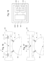
- the invention also relates to a timepiece movement 1000, comprising such a resonator 100, energy supply and/or storage means 300 arranged to supply at least one such resonator 100, which the movement 1000 comprises, and an escapement mechanism 200 comprising at least one escapement wheel set 2 arranged to cooperate in interaction with the at least one inertial wheel set 1 of the resonator 100.
- the at least one inertial wheel set 1 and the at least one escapement wheel set 2 with which it cooperates on the one hand comprise magnets which are permanent magnets, and on the other hand are devoid of ferromagnetic components and ferromagnetic zones, like the entire resonator 100 and the components of the escapement mechanism 200 other than the at least one escapement wheel set 2, which comprises escapement magnets 299, which are also devoid of them.
- the at least one inertial mobile 1 is arranged to cooperate in magnetic interaction, in a plane perpendicular to the oscillation axis D1 or oblique relative to the oscillation axis D1, with said at least one escapement mobile 2 and, where appropriate, a structural element 3, magnetized and/or ferromagnetic, which the movement 1000 comprises.
- the resultant of the magnetic moments of all the magnetic zones 10 carried by the at least one inertial mobile 1 has a zero component in any plane perpendicular to the axis of oscillation D1.
- the resultant of the magnetic moments of all the magnetic zones 10 carried by all the inertial mobiles 1 with the same oscillation axis D1, which the resonator 100 comprises, has a zero component in any plane perpendicular to the oscillation axis D1.
- a first set of magnetic zones is arranged for magnetic interaction with at least one escapement mobile 2 or a structural element 3, and a second set of magnetic zones is arranged to compensate the resultant of the magnetic moments of all the magnetic zones of the first set so that the resultant has a zero component in any plane perpendicular to the oscillation axis D1, and the second set of magnetic zones is further arranged so that the magnetic interaction forces of its constituents with any escapement mobile 2 or any structural element 3 of the resonator 100 are less than one tenth of the magnetic interaction forces of the constituents of the first set of magnetic zones with any escapement mobile 2 or any structural element 3 of the resonator 100.
- At least one escapement wheel 2 or at least one structural element 3, magnetized and/or ferromagnetic, which the movement 1000 comprises, and which is arranged to cooperate in magnetic interaction with at least one inertial wheel 1, has a resultant of the magnetic moments of all the magnetized zones and of all the magnets which it comprises having a zero component in any plane perpendicular to the oscillation axis D1 or in any plane perpendicular to its own oscillation axis if it is pivotally mounted.
- each escape wheel 2 or structural element 3, magnetized and/or ferromagnetic, that the movement 1000 comprises, and which is arranged to cooperate in magnetic interaction with at least one inertial wheel 1, has a resultant of the magnetic moments of all the magnetized zones and of all the magnets that it comprises having a zero component in any plane perpendicular to the oscillation axis D1 or in any plane perpendicular to its own oscillation axis if it is pivotally mounted.
- the second assembly comprises at least one balancing magnetized zone, and/or a balancing magnet 6, the position of the magnetic center of mass of which, as defined above, is not on the oscillation axis D1, and is adjusted by calculation to achieve magnetic balancing of the at least one inertial mobile 1.
- each magnetized area or magnet in the second set has a magnetic moment whose magnetic center of mass position is not on the oscillation axis D1.
- the second assembly comprises at least one balancing magnetized zone or a balancing magnet 6, the position of the magnetic center of mass of which is not on the oscillation axis D1 to achieve magnetic balancing of the at least one inertial mobile 1.
- each magnetized area or magnet in the first set has a magnetic moment whose magnetic center of mass position is not on the oscillation axis D1.
- the second assembly comprises at least one balancing magnetized zone, and/or a balancing magnet 6, the direction of the magnetic moment of which is along the oscillation axis D1, to achieve magnetic balancing of the at least one inertial mobile 1.
- the second assembly comprises at least one magnetized zone or one balancing magnet 6 whose position of the magnetic center of mass is, relative to the oscillation axis D1, opposite the magnetic center of mass of the other magnets embedded on the inertial mobile, in order to achieve magnetic balancing of the at least one inertial mobile 1.
- each inertial mobile 1 has a permanent magnetization.
- all the magnetized zones and all the magnets carried by at least one escapement wheel 2 or a structural element 3, which the movement 1000 comprises, have a permanent magnetization.
- all the magnetized areas and all the magnets carried by each escapement wheel 2 or structural element 3, which the movement 1000 comprises, have permanent magnetization.
- all the magnetic zones 10, and each at least one magnetized zone or each at least one balancing magnet 6, which the inertial mobile 1 comprises, have a permanent magnetization.
- this at least one inertial wheel set 1 and this at least one escapement wheel set 2 with which it cooperates respectively comprise magnetic zones 10 and at least one magnetized zone or one balancing magnet 6, and escapement magnets, which are all constituted by permanent magnets, and are, with the exception of the magnetic zones 10, the at least one magnetized zone or the at least one balancing magnet 6, and the escapement magnets 299, devoid of ferromagnetic components and ferromagnetic zones, like the entirety of the resonator 100 and the components of the escapement mechanism 200 other than the at least one escapement wheel set 2 and the inertial wheel set 1.
- the inertial mobile 1 is devoid of other ferromagnetic components and ferromagnetic zones, than the magnetic zones 10, the at least one magnetized zone or the at least one balancing magnet 6, which are all constituted by permanent magnets.
- all the magnetic zones 10, and each at least one magnetized zone or balancing magnet 6, and each at least one magnetic compensation element 4, which the inertial mobile 1 comprises, have a permanent magnetization.
- the inertial mobile 1 is devoid of other ferromagnetic components and ferromagnetic zones, than the magnetic zones 10, the at least one magnetized zone or the at least one balancing magnet 6, the at least one magnetic compensation element 4, all of which are made of permanent magnets.
- At least one inertial mobile 1 is a balance wheel
- at least one escapement mobile 2 is an escape wheel.
- the movement 1000 comprises at least one structural element 3, which is arranged to cooperate in magnetic interaction with the at least one inertial mobile 1 at a magnetic zone 13, 14 of the latter, and this structural element 3 is in particular a skewer 33 or a travel limiting stop of the at least one inertial mobile 1, or similar.
- the invention also relates to a timepiece 2000, in particular a watch, comprising at least one such movement 1000 and/or one such resonator 100.
- this 2000 watch features a case with magnetic shielding to enclose each 100 resonator that the 2000 watch features.
- the invention makes it possible to implement a method for reducing the sensitivity to an external magnetic field of a clock resonator 100 comprising internal means of magnetic interaction between, on the one hand, at least one inertial wheel set 1 of the resonator 100, pivotally mounted about an oscillation axis D1 and comprising magnetic elements 10, and, on the other hand, an escapement wheel set 2 or a structural element 3, magnetized and/or ferromagnetic, which the movement 1000 comprises.
- two reference axes OX and OY are defined, orthogonal to each other and to the oscillation axis D1.
- the figures illustrate more particularly, and in a non-limiting manner, the application of the invention to a resonator 100 with an inertial mobile 1 which is a balance.
- Each magnet 11, 12, carries a magnetic moment, it is an extensive vector quantity which is calculated as the integral of the magnetization over the entire volume of the magnet.
- the magnetic moment can be represented as the needle of a compass, which undergoes a torque when it is immersed in an external magnetic field.
- the magnetic moment should consist only of the ⁇ z component that is aligned with the Z axis.
- the total magnetic moment ⁇ tot is the sum of the magnetic moments of all the magnets carried by the resonator; this total magnetic moment should be aligned with the oscillation axis D1, Z axis in the figure, to guarantee the insensitivity of the resonator to external fields.
- the vector ⁇ tot is the sum of a vector ⁇ xy representing the component of the total resulting moment in the XOY plane perpendicular to the Z axis, and of the component ⁇ z on this same Z axis: in summary we seek to minimize, and if possible to cancel the component ⁇ xy . Because this component ⁇ xy of the total magnetic moment ⁇ tot will change direction when the pendulum 1 oscillates.
- an alignment defect produces such a small component ⁇ xy in the plane perpendicular to the oscillation axis, which behaves like the needle of a compass.
- an external magnetic field Bext produces a disturbing torque which depends on the position of the balance, and therefore a variation in rate. Indeed, it is known that such a disturbing torque, which varies non-linearly with the angle of the balance 1, affects the rate of the resonator 100.
- the first proposed improvement therefore consists of adding at least one compensation magnet 4 on the balance 1, as visible in the figure 4 .
- This is an additional magnet, which does not interact with the escape wheel 2, and whose component ⁇ c perpendicular to the oscillation axis D1 is adjusted to be of equal intensity but opposite direction to the component ⁇ xy (perpendicular to the oscillation axis D1) of the other magnets carried by the balance wheel 1, as visible on the figure 5 , to compensate for the effect of the magnetic moment ⁇ xy .
- the figure 5 shows that the total magnetic moment is then reduced to ⁇ z and is then aligned along OZ which corresponds to the oscillation axis D1 of balance 1.
- a radially magnetized cylindrical magnet can also be added, the resulting magnetization of which is zero. The adjustment is then made by removing part of this magnet, as seen in the figure 8 .
- micro-magnets magnetic pixels
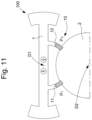
- each of these solutions for creating an adjustable compensation magnet is, advantageously, embedded on the balance 1, close to its oscillation axis D1, as shown in the figure. figure 11 which takes up the configuration of the figure 7 .
- FIG 12 shows a balance 1 with magnetic pallets 11 and 12 which are magnetized along the OZ axis, with a resulting magnetic moment ⁇ z1&2 which is positioned at the magnetic center of mass of pallets 11 and 12 (by analogy with the total mass of a mobile which is positioned at its center of mass).
- the figure 13 illustrates the displacement of this same magnetic moment resulting in an inhomogeneous magnetic field B z , illustrated here for example with a field intensity gradient along X, represented by progressive grayscale.
- the magnetic interaction energy varies non-linearly with the position of the pendulum 1 in this field.
- the resulting magnetic moment may be located on the oscillation axis D1 (point O).
- the magnetic pallets 11 and 12 which interact with the escape wheel 2 cannot be moved to this point.
- a second improvement proposal therefore consists of adding a balancing magnet 6, as visible on the figure 14 .
- This balancing magnet 6 is located opposite the escape wheel 2, relative to the oscillation axis D1, and sufficiently far from this escape wheel 2 so as not to interact with it.
- This balancing magnet 6 is magnetized in the direction of the oscillation axis D1. It is positioned opposite the position of the magnetic center of mass of the other magnets 11 and 12 embedded on the balance 1, as shown in figure 14 . In this way, the trajectory that the magnetic moment of the balancing magnet 6 describes in the external field B z produces, to the first order, a disturbing torque which is opposite to that which applies to the other magnets 11 and 12 embedded on the balance 1. Another way of explaining the role of this magnet is to speak of magnetic balancing. The objective is to bring back what can be called a magnetic center of mass of the magnetic moment on the oscillation axis D1. This magnetic center of mass is defined by the moments of order 1 (x B , y B , z B ) of the component of the total resulting magnetic moment which is in the direction of the oscillation axis D1.
- this magnetic balancing magnet can be added with several methods. It should be noted that the geometry and location of this balancing magnet can be calculated at the time of designing the vane magnets 11, 12, and the like. Therefore the balancing magnet 6 can be manufactured with the same technology that makes it possible to manufacture the vanes: traditional machining, laser, thin film deposition, or other. Another solution may be to add it at a later stage, for example by projecting magnetic material onto the balance rim, by additive manufacturing or jetting, or by any other suitable process, to balance it. Of course, this list is not exhaustive.
- the invention makes it possible to obtain good insensitivity of a resonator incorporating magnetic functions to external magnetic fields, without a significant increase in the volume of its components, and at a moderate cost.
- the invention is applicable both to new equipment and to mechanisms already manufactured, which can be improved under reasonable economic conditions, in complete safety.
- the invention is described here in the particular case of a resonator, which is the most sensitive organ of a timepiece, any disturbance of order magnetic being likely to have a direct impact on the operation by degrading it.
- the watchmaker will also know how to apply it to other less sensitive mechanisms of a watch, such as magnetic striking mechanisms, or others.
- the invention has been described in the preferred case of a magnetic interaction, its principle remains applicable to an electrostatic interaction, or even mixed magnetic and electrostatic.
Landscapes
- Physics & Mathematics (AREA)
- General Physics & Mathematics (AREA)
- Electromagnetism (AREA)
- Electric Clocks (AREA)
- Magnetic Bearings And Hydrostatic Bearings (AREA)
- Micromachines (AREA)
- Apparatuses For Generation Of Mechanical Vibrations (AREA)
- Particle Accelerators (AREA)
Claims (12)
- Uhrresonator (100), der ein Trägheitsdrehteil (1) beinhaltet, der angeordnet ist, um um eine Schwingungsachse (D1) herum zu oszillieren, und Rückstellmittel, um eine Oszillation des Trägheitsdrehteils (1) zu unterhalten, der mindestens einen magnetischen Bereich (10) beinhaltet, der für eine magnetische Wechselwirkung mit einem Hemmungsdrehteil (2) angeordnet ist und mindestens einen Magneten beinhaltet; dadurch gekennzeichnet, dass der Trägheitsdrehteil (1) eine erste Gesamtheit von magnetischen Bereichen (11, 12; 11 bis 14), die für die magnetische Wechselwirkung mit dem Hemmungsdrehteil (2), und gegebenenfalls für eine magnetische Wechselwirkung mit mindestens einem magnetisierten und/oder ferromagnetischen Strukturelement (3) angeordnet ist, das ein Uhrwerk umfasst, das den Resonator (100) beinhaltet, und eine zweite Gesamtheit von magnetischen Bereichen, die mindestens einen magnetisierten Bereich oder einen Auswuchtmagneten (6) beinhaltet, dessen Position des magnetischen Massenmittelpunkts sich in Bezug auf die Schwingungsachse auf der entgegengesetzten Seite des magnetischen Massenmittelpunkts der anderen magnetischen Bereiche befindet, die am Trägheitsdrehteil eingebaut sind, um eine magnetische Auswuchtung des Trägheitsdrehteils durchzuführen, wobei der magnetische Massenmittelpunkt (xB , yB , zB ) einer Gesamtheit von magnetischen Bereichen durch die Momente der Ordnung '1' gemäß der Schwingungsachse und zwei orthogonalen Bezugsachsen in einer Ebene senkrecht zu dieser Schwingungsachse, der Komponenten gemäß der Richtung der Schwingungsachse der jeweiligen magnetischen Momente definiert ist, und wobei die magnetische Auswuchtung des Trägheitsdrehteils durch einen auf der Schwingungsachse liegenden magnetische Massenmittelpunkt dieses Trägheitsdrehteils definiert ist.
- Resonator (100) nach Anspruch 1, dadurch gekennzeichnet, dass die zweite Gesamtheit von magnetischen Bereichen weiter angeordnet ist, damit die magnetischen Wechselwirkungskräfte seiner Bestandteile mit jedem Hemmungsdrehteil (2) oder oder jedem Strukturelement (3) weniger als ein Zehntel der magnetischen Wechselwirkungskräfte der Bestandteile der ersten Gesamtheit von magnetischen Bereichen mit jedem Hemmungsdrehteil oder jedem Strukturelement betragen.
- Resonator (100) nach Anspruch 1 oder 2, dadurch gekennzeichnet, dass die zweite Gesamtheit von magnetischen Bereichen auch angeordnet ist, um die Resultierende der magnetischen Momente aller magnetischen Bereiche der ersten Gesamtheit zu kompensieren, sodass das gesamte resultierende magnetische Moment aller magnetischen Bereiche des Trägheitsdrehteils in der Richtung der Schwingungsachse (D1) ausgerichtet ist.
- Resonator (100) nach einem der Ansprüche 1 bis 3, dadurch gekennzeichnet, dass die magnetischen Bereiche (10) der ersten Gesamtheit und jeder magnetisierte Bereich oder Auswuchtmagnet (6) eine permanente Magnetisierung aufweisen.
- Resonator (100) nach Anspruch 3, dadurch gekennzeichnet, dass der Trägheitsdrehteil (1) mindestens ein magnetisches Kompensationselement (4) trägt, das in der zweiten Gesamtheit umfasst ist, dessen Magnetisierungskomponente senkrecht zur Schwingungsachse (D1) einstellbar ist, um das gesamte resultierende magnetische Moment zu erhalten, das in der Richtung der Schwingungsachse ausgerichtet ist.
- Uhrwerk (1000), das einen Resonator (100) nach einem der Ansprüche 1 bis 5 beinhaltet, und einen Hemmungsmechanismus (200), der mindestens einen Hemmungsdrehteil (2) beinhaltet, das angeordnet ist, um in magnetischer Wechselwirkung mit dem genannten Trägheitsdrehteil (1) zusammenzuwirken, und Energieversorgungs- und/oder -speichermittel (300), die angeordnet sind, um den Resonator (100) zu versorgen, dadurch gekennzeichnet, dass die Resultierende der magnetischen Momente aller magnetischen Bereiche, die der Trägheitsdrehteil (1) trägt, in jeder Ebene senkrecht zur Schwingungsachse (D1) eine Nullkomponente aufweist.
- Uhrwerk (1000) nach Anspruch 6, dadurch gekennzeichnet, dass der Trägheitsdrehteil (1) angeordnet ist, um in einer Ebene senkrecht zur Schwingungsachse (D1) oder schräg in Bezug zur Schwingungsachse (D1) in magnetischer Wechselwirkung mit dem mindestens einen Hemmungsdrehteil (2) und gegebenenfalls mindestens einem magnetischen und/oder ferromagnetischen Strukturelement (3), welches das Uhrwerk beinhaltet, zusammenzuwirken.
- Uhrwerk (1000) nach Anspruch 6 oder 7, dadurch gekennzeichnet, dass alle magnetisierten Bereiche und alle Magnete, die ein Hemmungsdrehteil (2) oder ein Strukturelement (3), welches das Uhrwerk (1000) beinhaltet, tragen, eine permanente Magnetisierung aufweisen.
- Uhrwerk (1000) nach einem der Ansprüche 6 bis 8, dadurch gekennzeichnet, dass der Trägheitsdrehteil (1) eine Unruh ist und dadurch, dass mindestens ein Hemmungsdrehteil (2) ein Hemmungsrad ist.
- Uhrwerk (1000) nach einem der Ansprüche 6 bis 9, dadurch gekennzeichnet, dass es mindestens ein sogenanntes Strukturelement (3) beinhaltet, das angeordnet ist, um in magnetischer Wechselwirkung mit dem Trägheitsdrehteil (1) zusammenzuwirken, und das ein Sperrstift oder ein Anschlag zur Begrenzung des Weges des Trägheitsdrehteils ist.
- Uhr (2000), die mindestens ein Uhrwerk (1000) nach einem der Ansprüche 6 bis 10 beinhaltet.
- Uhr (2000) nach Anspruch 11, dadurch gekennzeichnet, dass sie ein Gehäuse mit einer magnetischen Abschirmung beinhaltet, um den Resonator (100), den diese Uhr beinhaltet, einzuschließen.
Applications Claiming Priority (1)
| Application Number | Priority Date | Filing Date | Title |
|---|---|---|---|
| EP19182712.0A EP3757684B1 (de) | 2019-06-26 | 2019-06-26 | Trägheitsbewegungselement für uhrresonator mit einer vorrichtung zur magnetischen wechselwirkung, die gegenüber dem äusseren magnetfeld unempfindlich ist |
Publications (2)
| Publication Number | Publication Date |
|---|---|
| EP3757685A1 EP3757685A1 (de) | 2020-12-30 |
| EP3757685B1 true EP3757685B1 (de) | 2024-11-20 |
Family
ID=67105777
Family Applications (2)
| Application Number | Title | Priority Date | Filing Date |
|---|---|---|---|
| EP19182712.0A Active EP3757684B1 (de) | 2019-06-26 | 2019-06-26 | Trägheitsbewegungselement für uhrresonator mit einer vorrichtung zur magnetischen wechselwirkung, die gegenüber dem äusseren magnetfeld unempfindlich ist |
| EP20176609.4A Active EP3757685B1 (de) | 2019-06-26 | 2020-05-26 | Trägheitsbewegungselement für uhrresonator mit einer vorrichtung zur magnetischen wechselwirkung, die gegenüber dem äusseren magnetfeld unempfindlich ist |
Family Applications Before (1)
| Application Number | Title | Priority Date | Filing Date |
|---|---|---|---|
| EP19182712.0A Active EP3757684B1 (de) | 2019-06-26 | 2019-06-26 | Trägheitsbewegungselement für uhrresonator mit einer vorrichtung zur magnetischen wechselwirkung, die gegenüber dem äusseren magnetfeld unempfindlich ist |
Country Status (4)
| Country | Link |
|---|---|
| US (2) | US11599064B2 (de) |
| EP (2) | EP3757684B1 (de) |
| JP (2) | JP7028915B2 (de) |
| CN (2) | CN112147873B (de) |
Family Cites Families (18)
| Publication number | Priority date | Publication date | Assignee | Title |
|---|---|---|---|---|
| US2682744A (en) * | 1950-12-09 | 1954-07-06 | Chilowsky Constantin | Means for and method of accurately regulating chronometric devices |
| FR1113932A (fr) | 1953-11-07 | 1956-04-05 | Horstmann Magnetics Ltd | Mécanisme comportant des systèmes oscillant et rotatif accouplés magnétiquement |
| US2946183A (en) | 1955-06-14 | 1960-07-26 | Horstmann Magnetics Ltd | Self-starting magnetic escapement mechanisms |
| DE7009864U (de) | 1970-03-17 | 1970-11-26 | Junghans Gmbh Geb | Vorrichtung zum magnetischen arretieren eines schaltrades eines zeithaltenden geraetes. |
| GB1361672A (en) | 1971-03-30 | 1974-07-30 | Horstmann Magnetics Ltd | Magnetic rotor drives |
| CH67274A4 (de) | 1974-01-18 | 1975-09-15 | ||
| EP2450758B1 (de) * | 2010-11-09 | 2017-01-04 | Montres Breguet SA | Magnetischer Drehzapfen und elektrostatischer Dhrerzapfen |
| CH707471B1 (fr) | 2013-08-05 | 2014-07-31 | Rd Engineering Rudolf Dinger | Système régulateur pour montre mécanique. |
| EP3299907A1 (de) * | 2013-12-23 | 2018-03-28 | ETA SA Manufacture Horlogère Suisse | Mechanisches uhrwerk mit magnetischem hemmungsmechanismus |
| EP2887157B1 (de) * | 2013-12-23 | 2018-02-07 | The Swatch Group Research and Development Ltd. | Optimierte uhrhemmung |
| EP2887156B1 (de) | 2013-12-23 | 2018-03-07 | The Swatch Group Research and Development Ltd. | Einstellvorrichtung |
| US9483026B2 (en) | 2013-12-23 | 2016-11-01 | The Swatch Group Research And Development Ltd. | Angular speed regulating device for a wheel set in a timepiece movement including a magnetic escapement mechanism |
| EP3095010B1 (de) * | 2014-01-13 | 2024-09-25 | Ecole Polytechnique Fédérale de Lausanne (EPFL) | Isotroper harmonischer oszillator und zugehörige zeitbasis ohne hemmung oder mit vereinfachter hemmung |
| EP3176650B1 (de) * | 2015-12-02 | 2019-02-06 | Nivarox-FAR S.A. | Schutz einer uhrkomponente aus mikro-bearbeitbarem material |
| EP3185080B1 (de) * | 2015-12-22 | 2019-12-18 | Montres Breguet S.A. | Uhrmechanismus, der ein schwenkorgan umfasst, das mit magnetischen rückstellmitteln ausgestattet ist |
| CH711965A2 (fr) | 2015-12-23 | 2017-06-30 | Montres Breguet Sa | Mouvement horloger mécanique avec un échappement à ancre. |
| CH712726A2 (fr) * | 2016-07-21 | 2018-01-31 | Montres Breguet Sa | Oscillateur balancier-spiral d'horlogerie à pivot magnétique. |
| EP3316046B1 (de) | 2016-10-25 | 2019-07-31 | The Swatch Group Research and Development Ltd | Verbessertes uhrwerk |
-
2019
- 2019-06-26 EP EP19182712.0A patent/EP3757684B1/de active Active
-
2020
- 2020-05-26 EP EP20176609.4A patent/EP3757685B1/de active Active
- 2020-06-09 US US16/896,613 patent/US11599064B2/en active Active
- 2020-06-09 US US16/896,579 patent/US11644797B2/en active Active
- 2020-06-19 JP JP2020105797A patent/JP7028915B2/ja active Active
- 2020-06-19 JP JP2020105795A patent/JP7028914B2/ja active Active
- 2020-06-24 CN CN202010595166.8A patent/CN112147873B/zh active Active
- 2020-06-24 CN CN202010587552.2A patent/CN112147872B/zh active Active
Also Published As
| Publication number | Publication date |
|---|---|
| JP2021004879A (ja) | 2021-01-14 |
| US11644797B2 (en) | 2023-05-09 |
| EP3757684B1 (de) | 2024-10-16 |
| CN112147872B (zh) | 2022-06-28 |
| US20200409310A1 (en) | 2020-12-31 |
| EP3757685A1 (de) | 2020-12-30 |
| CN112147873A (zh) | 2020-12-29 |
| CN112147873B (zh) | 2022-05-06 |
| JP2021004880A (ja) | 2021-01-14 |
| CN112147872A (zh) | 2020-12-29 |
| US20200409311A1 (en) | 2020-12-31 |
| JP7028915B2 (ja) | 2022-03-02 |
| US11599064B2 (en) | 2023-03-07 |
| EP3757684A1 (de) | 2020-12-30 |
| JP7028914B2 (ja) | 2022-03-02 |
Similar Documents
| Publication | Publication Date | Title |
|---|---|---|
| EP3130966B1 (de) | Mechanisches uhrwerk, das mit einem bewegungsrückkopplungssysteme ausgestattet ist | |
| EP2990885B1 (de) | Mechanisches Uhrwerk mit magnetischem Hemmungsmechanismus | |
| EP1805565B1 (de) | Armbanduhr-regulierungsglied und mechanisches uhrwerk mit einem solchen regulierungsglied | |
| EP3545370B1 (de) | Rotierender resonator mit flexiblem führungssystem auf basis einer abgelösten ankerhemmung | |
| EP2466401B1 (de) | Magnetischer Resonator für eine mechanische Uhr | |
| EP2487547B1 (de) | Regulator einer Triebfeder eines Uhrwerks oder eines Schlagwerks | |
| EP3208667B1 (de) | Magnetisches hemmungsdrehteil eines uhrwerks | |
| EP1521142B1 (de) | Uhr mit einem mechanischen Uhrwerk, das mit einem elektronischen Regulator gekoppelt ist | |
| EP1521141A1 (de) | Uhr mit einem mechanischen Uhrwerk, das mit einem elektronischen Regulator gekoppelt ist | |
| EP2891930A2 (de) | Vorrichtung zur Regulierung der Winkelgeschwindigkeit einer Triebfeder in einem Uhrwerk, das einen magnetischen Hemmungsmechanismus umfasst | |
| EP3191899A1 (de) | Magnetische uhrenhemmung und reglervorrichtung zum betrieb eines uhrwerks | |
| EP3030938A2 (de) | Reglersystem für eine mechanische uhr | |
| EP2466397B1 (de) | Drehteil einer Uhr mit peripherem Antrieb | |
| EP3757685B1 (de) | Trägheitsbewegungselement für uhrresonator mit einer vorrichtung zur magnetischen wechselwirkung, die gegenüber dem äusseren magnetfeld unempfindlich ist | |
| EP3185083B1 (de) | Mechanischer uhrmechanismus mit einer ankerhemmung | |
| EP2309344B1 (de) | Verfahren zur Veränderung der Oszillationsfrequenz eines Uhrwerks | |
| CH716347A2 (fr) | Mobile inertiel pour résonateur d'horlogerie avec dispositif d'interaction magnétique insensible au champ magnétique externe. | |
| EP3265879B1 (de) | Zeitmessendes uhrwerk mit einem regler mit dreidimensionaler magnetischer resonanz | |
| CH712154B1 (fr) | Mobile d'échappement magnétique d'horlogerie. | |
| EP3663868A1 (de) | Uhrwerk, das ein tourbillon mit einem festen magnetischen rad umfasst | |
| WO2021009613A1 (fr) | Procede de reglage d'un oscillateur horloger a pivot flexible | |
| CH714600A2 (fr) | Pièce d'horlogerie munie d'un tourbillon. | |
| CH711965A2 (fr) | Mouvement horloger mécanique avec un échappement à ancre. | |
| CH715618A2 (fr) | Mouvement d'horlogerie comportant un tourbillon avec une roue magnétique fixe. | |
| EP3373081A1 (de) | Uhrwerk, das mit einer vorrichtung zur positionierung eines mobilen elements in einer vielzahl von diskreten positionen ausgestattet ist |
Legal Events
| Date | Code | Title | Description |
|---|---|---|---|
| PUAI | Public reference made under article 153(3) epc to a published international application that has entered the european phase |
Free format text: ORIGINAL CODE: 0009012 |
|
| STAA | Information on the status of an ep patent application or granted ep patent |
Free format text: STATUS: THE APPLICATION HAS BEEN PUBLISHED |
|
| AK | Designated contracting states |
Kind code of ref document: A1 Designated state(s): AL AT BE BG CH CY CZ DE DK EE ES FI FR GB GR HR HU IE IS IT LI LT LU LV MC MK MT NL NO PL PT RO RS SE SI SK SM TR |
|
| AX | Request for extension of the european patent |
Extension state: BA ME |
|
| STAA | Information on the status of an ep patent application or granted ep patent |
Free format text: STATUS: REQUEST FOR EXAMINATION WAS MADE |
|
| 17P | Request for examination filed |
Effective date: 20210630 |
|
| RBV | Designated contracting states (corrected) |
Designated state(s): AL AT BE BG CH CY CZ DE DK EE ES FI FR GB GR HR HU IE IS IT LI LT LU LV MC MK MT NL NO PL PT RO RS SE SI SK SM TR |
|
| RIN1 | Information on inventor provided before grant (corrected) |
Inventor name: DI DOMENICO, GIANNI Inventor name: FAVRE, JEROME Inventor name: MATTHEY, OLIVIER Inventor name: LECHOT, DOMINIQUE Inventor name: HINAUX, BAPTISTE Inventor name: NAGY, LAURENT Inventor name: MARTIN, JEAN-CLAUDE |
|
| STAA | Information on the status of an ep patent application or granted ep patent |
Free format text: STATUS: EXAMINATION IS IN PROGRESS |
|
| 17Q | First examination report despatched |
Effective date: 20230301 |
|
| P01 | Opt-out of the competence of the unified patent court (upc) registered |
Effective date: 20230615 |
|
| GRAP | Despatch of communication of intention to grant a patent |
Free format text: ORIGINAL CODE: EPIDOSNIGR1 |
|
| STAA | Information on the status of an ep patent application or granted ep patent |
Free format text: STATUS: GRANT OF PATENT IS INTENDED |
|
| INTG | Intention to grant announced |
Effective date: 20240806 |
|
| GRAS | Grant fee paid |
Free format text: ORIGINAL CODE: EPIDOSNIGR3 |
|
| GRAA | (expected) grant |
Free format text: ORIGINAL CODE: 0009210 |
|
| STAA | Information on the status of an ep patent application or granted ep patent |
Free format text: STATUS: THE PATENT HAS BEEN GRANTED |
|
| AK | Designated contracting states |
Kind code of ref document: B1 Designated state(s): AL AT BE BG CH CY CZ DE DK EE ES FI FR GB GR HR HU IE IS IT LI LT LU LV MC MK MT NL NO PL PT RO RS SE SI SK SM TR |
|
| REG | Reference to a national code |
Ref country code: GB Ref legal event code: FG4D Free format text: NOT ENGLISH |
|
| RIN1 | Information on inventor provided before grant (corrected) |
Inventor name: MARTIN, JEAN-CLAUDE Inventor name: NAGY, LAURENT Inventor name: HINAUX, BAPTISTE Inventor name: LECHOT, DOMINIQUE Inventor name: MATTHEY, OLIVIER Inventor name: FAVRE, JEROME Inventor name: DI DOMENICO, GIANNI |
|
| REG | Reference to a national code |
Ref country code: CH Ref legal event code: EP |
|
| REG | Reference to a national code |
Ref country code: DE Ref legal event code: R096 Ref document number: 602020041547 Country of ref document: DE |
|
| REG | Reference to a national code |
Ref country code: IE Ref legal event code: FG4D Free format text: LANGUAGE OF EP DOCUMENT: FRENCH |
|
| REG | Reference to a national code |
Ref country code: LT Ref legal event code: MG9D |
|
| REG | Reference to a national code |
Ref country code: NL Ref legal event code: MP Effective date: 20241120 |
|
| PG25 | Lapsed in a contracting state [announced via postgrant information from national office to epo] |
Ref country code: HR Free format text: LAPSE BECAUSE OF FAILURE TO SUBMIT A TRANSLATION OF THE DESCRIPTION OR TO PAY THE FEE WITHIN THE PRESCRIBED TIME-LIMIT Effective date: 20241120 Ref country code: IS Free format text: LAPSE BECAUSE OF FAILURE TO SUBMIT A TRANSLATION OF THE DESCRIPTION OR TO PAY THE FEE WITHIN THE PRESCRIBED TIME-LIMIT Effective date: 20250320 Ref country code: PT Free format text: LAPSE BECAUSE OF FAILURE TO SUBMIT A TRANSLATION OF THE DESCRIPTION OR TO PAY THE FEE WITHIN THE PRESCRIBED TIME-LIMIT Effective date: 20250320 |
|
| PG25 | Lapsed in a contracting state [announced via postgrant information from national office to epo] |
Ref country code: FI Free format text: LAPSE BECAUSE OF FAILURE TO SUBMIT A TRANSLATION OF THE DESCRIPTION OR TO PAY THE FEE WITHIN THE PRESCRIBED TIME-LIMIT Effective date: 20241120 Ref country code: NL Free format text: LAPSE BECAUSE OF FAILURE TO SUBMIT A TRANSLATION OF THE DESCRIPTION OR TO PAY THE FEE WITHIN THE PRESCRIBED TIME-LIMIT Effective date: 20241120 |
|
| REG | Reference to a national code |
Ref country code: AT Ref legal event code: MK05 Ref document number: 1744130 Country of ref document: AT Kind code of ref document: T Effective date: 20241120 |
|
| PG25 | Lapsed in a contracting state [announced via postgrant information from national office to epo] |
Ref country code: BG Free format text: LAPSE BECAUSE OF FAILURE TO SUBMIT A TRANSLATION OF THE DESCRIPTION OR TO PAY THE FEE WITHIN THE PRESCRIBED TIME-LIMIT Effective date: 20241120 |
|
| PG25 | Lapsed in a contracting state [announced via postgrant information from national office to epo] |
Ref country code: ES Free format text: LAPSE BECAUSE OF FAILURE TO SUBMIT A TRANSLATION OF THE DESCRIPTION OR TO PAY THE FEE WITHIN THE PRESCRIBED TIME-LIMIT Effective date: 20241120 |
|
| PG25 | Lapsed in a contracting state [announced via postgrant information from national office to epo] |
Ref country code: NO Free format text: LAPSE BECAUSE OF FAILURE TO SUBMIT A TRANSLATION OF THE DESCRIPTION OR TO PAY THE FEE WITHIN THE PRESCRIBED TIME-LIMIT Effective date: 20250220 |
|
| PG25 | Lapsed in a contracting state [announced via postgrant information from national office to epo] |
Ref country code: LV Free format text: LAPSE BECAUSE OF FAILURE TO SUBMIT A TRANSLATION OF THE DESCRIPTION OR TO PAY THE FEE WITHIN THE PRESCRIBED TIME-LIMIT Effective date: 20241120 Ref country code: GR Free format text: LAPSE BECAUSE OF FAILURE TO SUBMIT A TRANSLATION OF THE DESCRIPTION OR TO PAY THE FEE WITHIN THE PRESCRIBED TIME-LIMIT Effective date: 20250221 Ref country code: AT Free format text: LAPSE BECAUSE OF FAILURE TO SUBMIT A TRANSLATION OF THE DESCRIPTION OR TO PAY THE FEE WITHIN THE PRESCRIBED TIME-LIMIT Effective date: 20241120 |
|
| PG25 | Lapsed in a contracting state [announced via postgrant information from national office to epo] |
Ref country code: PL Free format text: LAPSE BECAUSE OF FAILURE TO SUBMIT A TRANSLATION OF THE DESCRIPTION OR TO PAY THE FEE WITHIN THE PRESCRIBED TIME-LIMIT Effective date: 20241120 |
|
| PG25 | Lapsed in a contracting state [announced via postgrant information from national office to epo] |
Ref country code: RS Free format text: LAPSE BECAUSE OF FAILURE TO SUBMIT A TRANSLATION OF THE DESCRIPTION OR TO PAY THE FEE WITHIN THE PRESCRIBED TIME-LIMIT Effective date: 20250220 |
|
| PG25 | Lapsed in a contracting state [announced via postgrant information from national office to epo] |
Ref country code: SM Free format text: LAPSE BECAUSE OF FAILURE TO SUBMIT A TRANSLATION OF THE DESCRIPTION OR TO PAY THE FEE WITHIN THE PRESCRIBED TIME-LIMIT Effective date: 20241120 |
|
| PGFP | Annual fee paid to national office [announced via postgrant information from national office to epo] |
Ref country code: DE Payment date: 20250423 Year of fee payment: 6 |
|
| PG25 | Lapsed in a contracting state [announced via postgrant information from national office to epo] |
Ref country code: DK Free format text: LAPSE BECAUSE OF FAILURE TO SUBMIT A TRANSLATION OF THE DESCRIPTION OR TO PAY THE FEE WITHIN THE PRESCRIBED TIME-LIMIT Effective date: 20241120 |
|
| PG25 | Lapsed in a contracting state [announced via postgrant information from national office to epo] |
Ref country code: EE Free format text: LAPSE BECAUSE OF FAILURE TO SUBMIT A TRANSLATION OF THE DESCRIPTION OR TO PAY THE FEE WITHIN THE PRESCRIBED TIME-LIMIT Effective date: 20241120 |
|
| PGFP | Annual fee paid to national office [announced via postgrant information from national office to epo] |
Ref country code: FR Payment date: 20250423 Year of fee payment: 6 |
|
| PGFP | Annual fee paid to national office [announced via postgrant information from national office to epo] |
Ref country code: CH Payment date: 20250601 Year of fee payment: 6 |
|
| PG25 | Lapsed in a contracting state [announced via postgrant information from national office to epo] |
Ref country code: RO Free format text: LAPSE BECAUSE OF FAILURE TO SUBMIT A TRANSLATION OF THE DESCRIPTION OR TO PAY THE FEE WITHIN THE PRESCRIBED TIME-LIMIT Effective date: 20241120 |
|
| PG25 | Lapsed in a contracting state [announced via postgrant information from national office to epo] |
Ref country code: SK Free format text: LAPSE BECAUSE OF FAILURE TO SUBMIT A TRANSLATION OF THE DESCRIPTION OR TO PAY THE FEE WITHIN THE PRESCRIBED TIME-LIMIT Effective date: 20241120 |
|
| PG25 | Lapsed in a contracting state [announced via postgrant information from national office to epo] |
Ref country code: CZ Free format text: LAPSE BECAUSE OF FAILURE TO SUBMIT A TRANSLATION OF THE DESCRIPTION OR TO PAY THE FEE WITHIN THE PRESCRIBED TIME-LIMIT Effective date: 20241120 |
|
| PG25 | Lapsed in a contracting state [announced via postgrant information from national office to epo] |
Ref country code: IT Free format text: LAPSE BECAUSE OF FAILURE TO SUBMIT A TRANSLATION OF THE DESCRIPTION OR TO PAY THE FEE WITHIN THE PRESCRIBED TIME-LIMIT Effective date: 20241120 |
|
| REG | Reference to a national code |
Ref country code: DE Ref legal event code: R097 Ref document number: 602020041547 Country of ref document: DE |
|
| PG25 | Lapsed in a contracting state [announced via postgrant information from national office to epo] |
Ref country code: SE Free format text: LAPSE BECAUSE OF FAILURE TO SUBMIT A TRANSLATION OF THE DESCRIPTION OR TO PAY THE FEE WITHIN THE PRESCRIBED TIME-LIMIT Effective date: 20241120 |
|
| PLBE | No opposition filed within time limit |
Free format text: ORIGINAL CODE: 0009261 |
|
| STAA | Information on the status of an ep patent application or granted ep patent |
Free format text: STATUS: NO OPPOSITION FILED WITHIN TIME LIMIT |
|
| 26N | No opposition filed |
Effective date: 20250821 |