EP3316046B1 - Verbessertes uhrwerk - Google Patents
Verbessertes uhrwerk Download PDFInfo
- Publication number
- EP3316046B1 EP3316046B1 EP16195405.2A EP16195405A EP3316046B1 EP 3316046 B1 EP3316046 B1 EP 3316046B1 EP 16195405 A EP16195405 A EP 16195405A EP 3316046 B1 EP3316046 B1 EP 3316046B1
- Authority
- EP
- European Patent Office
- Prior art keywords
- pivot axis
- escape wheel
- movement
- magnetized
- inertial element
- Prior art date
- Legal status (The legal status is an assumption and is not a legal conclusion. Google has not performed a legal analysis and makes no representation as to the accuracy of the status listed.)
- Active
Links
- 230000007246 mechanism Effects 0.000 claims description 29
- 230000009975 flexible effect Effects 0.000 claims description 8
- 230000009471 action Effects 0.000 claims description 3
- 238000012937 correction Methods 0.000 claims description 3
- 238000012423 maintenance Methods 0.000 description 6
- 230000010355 oscillation Effects 0.000 description 4
- 230000035939 shock Effects 0.000 description 3
- 238000013459 approach Methods 0.000 description 1
- 230000008878 coupling Effects 0.000 description 1
- 238000010168 coupling process Methods 0.000 description 1
- 238000005859 coupling reaction Methods 0.000 description 1
- 238000011161 development Methods 0.000 description 1
- 238000010586 diagram Methods 0.000 description 1
- 230000006872 improvement Effects 0.000 description 1
- 230000002093 peripheral effect Effects 0.000 description 1
- 238000011160 research Methods 0.000 description 1
Images


Classifications
-
- G—PHYSICS
- G04—HOROLOGY
- G04B—MECHANICALLY-DRIVEN CLOCKS OR WATCHES; MECHANICAL PARTS OF CLOCKS OR WATCHES IN GENERAL; TIME PIECES USING THE POSITION OF THE SUN, MOON OR STARS
- G04B15/00—Escapements
-
- G—PHYSICS
- G04—HOROLOGY
- G04C—ELECTROMECHANICAL CLOCKS OR WATCHES
- G04C5/00—Electric or magnetic means for converting oscillatory to rotary motion in time-pieces, i.e. electric or magnetic escapements
- G04C5/005—Magnetic or electromagnetic means
-
- G—PHYSICS
- G04—HOROLOGY
- G04B—MECHANICALLY-DRIVEN CLOCKS OR WATCHES; MECHANICAL PARTS OF CLOCKS OR WATCHES IN GENERAL; TIME PIECES USING THE POSITION OF THE SUN, MOON OR STARS
- G04B1/00—Driving mechanisms
-
- G—PHYSICS
- G04—HOROLOGY
- G04B—MECHANICALLY-DRIVEN CLOCKS OR WATCHES; MECHANICAL PARTS OF CLOCKS OR WATCHES IN GENERAL; TIME PIECES USING THE POSITION OF THE SUN, MOON OR STARS
- G04B15/00—Escapements
- G04B15/06—Free escapements
-
- G—PHYSICS
- G04—HOROLOGY
- G04B—MECHANICALLY-DRIVEN CLOCKS OR WATCHES; MECHANICAL PARTS OF CLOCKS OR WATCHES IN GENERAL; TIME PIECES USING THE POSITION OF THE SUN, MOON OR STARS
- G04B15/00—Escapements
- G04B15/10—Escapements with constant impulses for the regulating mechanism
-
- G—PHYSICS
- G04—HOROLOGY
- G04B—MECHANICALLY-DRIVEN CLOCKS OR WATCHES; MECHANICAL PARTS OF CLOCKS OR WATCHES IN GENERAL; TIME PIECES USING THE POSITION OF THE SUN, MOON OR STARS
- G04B17/00—Mechanisms for stabilising frequency
- G04B17/04—Oscillators acting by spring tension
-
- G—PHYSICS
- G04—HOROLOGY
- G04B—MECHANICALLY-DRIVEN CLOCKS OR WATCHES; MECHANICAL PARTS OF CLOCKS OR WATCHES IN GENERAL; TIME PIECES USING THE POSITION OF THE SUN, MOON OR STARS
- G04B17/00—Mechanisms for stabilising frequency
- G04B17/04—Oscillators acting by spring tension
- G04B17/10—Oscillators with torsion strips or springs acting in the same manner as torsion strips, e.g. weight oscillating in a horizontal plane
-
- G—PHYSICS
- G04—HOROLOGY
- G04B—MECHANICALLY-DRIVEN CLOCKS OR WATCHES; MECHANICAL PARTS OF CLOCKS OR WATCHES IN GENERAL; TIME PIECES USING THE POSITION OF THE SUN, MOON OR STARS
- G04B17/00—Mechanisms for stabilising frequency
- G04B17/20—Compensation of mechanisms for stabilising frequency
- G04B17/26—Compensation of mechanisms for stabilising frequency for the effect of variations of the impulses
-
- G—PHYSICS
- G04—HOROLOGY
- G04C—ELECTROMECHANICAL CLOCKS OR WATCHES
- G04C3/00—Electromechanical clocks or watches independent of other time-pieces and in which the movement is maintained by electric means
- G04C3/08—Electromechanical clocks or watches independent of other time-pieces and in which the movement is maintained by electric means wherein movement is regulated by a mechanical oscillator other than a pendulum or balance, e.g. by a tuning fork, e.g. electrostatically
-
- G—PHYSICS
- G04—HOROLOGY
- G04B—MECHANICALLY-DRIVEN CLOCKS OR WATCHES; MECHANICAL PARTS OF CLOCKS OR WATCHES IN GENERAL; TIME PIECES USING THE POSITION OF THE SUN, MOON OR STARS
- G04B17/00—Mechanisms for stabilising frequency
- G04B17/04—Oscillators acting by spring tension
- G04B17/045—Oscillators acting by spring tension with oscillating blade springs
Definitions
- the invention relates to a clockwork mechanical movement, comprising a blade resonator mechanism which comprises at least one inertial element oscillating about a first axis of pivoting under the action of mechanical elastic return means comprising a plurality of fixed flexible blades on the one hand, directly or indirectly, to a structure of said resonator mechanism, and on the other hand, directly or indirectly, to said at least one inertial element, said resonator mechanism being coupled with a magnetic exhaust mechanism which comprises at least one movable escapement pivoting about a second pivot axis and subjected to a torque exerted by at least one energy source, and said at least one inertial element having at least two first magnetized zones at its periphery, arranged to cooperate directly with second magnetic zones that includes a said exhaust mobile and partially superimposed with i projected on a projection plane perpendicular to said first pivot axis.
- the invention also relates to a watch comprising at least one such movement.
- the invention further relates to a magnetic escape wheel arranged to pivot about a second pivot axis, and having magnetic zones at its periphery.
- the invention relates to the field of watch movements comprising blade resonators, and comprising magnetic escape mechanisms.
- Magnetic escapements have been known since the years 1960-1970, and have been the subject of patent applications: US 2946183 in the name of Clifford , JPS 5240366 , JPS 5245468U , JPS 5263453U . These devices are often not easy to integrate into a watch, because of their size. Above all, they have the disadvantage of being anisochronous, that is to say that the maintenance disrupts the resonator operation, and the value of this disturbance of operation varies with the amplitude of oscillation.
- the invention proposes to make an isochronous mechanical oscillator comprising a flexible blade resonator maintained by a magnetic escapement.
- the anisochronism of the resonator must be compensated for by the anisochronism of the exhaust delay.
- the isochronism corrector is an improvement of the exhaust which aims to achieve this compensation.
- the invention thus relates to an oscillator comprising a resonator with flexible blades maintained by a magnetic escapement with isochronism corrector.
- the invention relates to a watch movement according to claim 1.
- the invention also relates to a watch comprising at least one such movement.
- the invention further relates to a magnetic escape wheel according to claim 11.
- the present description is based, in a non-limiting manner, on the magnetic escape mechanism described in the document WO2015 097172 .
- the escape wheel is arranged with magnets in a particular configuration, and in zones that make it possible to produce a small controlled disturbance on the variation of the path due to the maintenance.
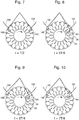
- FIG. 1 and 2 An oscillator according to the invention is illustrated by the Figures 1 and 2 .
- This oscillator comprises a resonator with flexible blades, maintained by a magnetic escapement.
- Two magnets located on the inertial mobile of the resonator are here sandwiched between two disks, which includes, in this particular non-limiting case, the escape wheel.
- the magnetic escape mechanism can also be at a single level
- At least one disc of the escape wheel comprises a first row of peripheral, tangential or substantially tangential magnets, hereinafter referred to as "tangential magnets", which are the magnets intended to cooperate in repulsion with the magnets of the resonator.
- At least one disc of the escape wheel comprises a second row of compensating magnets, whose function is to adjust the exhaust delay, so as to compensate for the possible anisochronism of the resonator, way to get an oscillator that is globally isochronous.
- these compensating magnets are radial, or substantially radial, and are hereinafter referred to as "radial magnets",
- one of the tangential magnets of the escape wheel approaches the position of the right magnet, said first magnet, of the resonator which is thus pushed to the right, and the magnet of the left, said second magnet , the resonator then enters the air gap of the escape wheel in an area where there is no tangential magnet.
- the isochronism corrector results from the cooperation of compensating magnets of the escape wheel with the first magnet or the second magnet of the resonator.
- we can influence the progress of the oscillator by positioning magnets, and in particular these radial magnets, near the magnet of the resonator which enters the escape wheel. The same goes for the second alternation between t 5T / 8 and 7T / 8.
- the residual anisochronism that must be corrected is weak, whether it comes from the exhaust or the resonator. Therefore, care must be taken to produce a variation in operation that is low and whose value varies with the amplitude of oscillation.
- the compensating magnets substantially in the radial direction on the wheel, or strictly in the radial direction of the wheel as illustrated in the figures, in an area adjacent to the trajectory of the wheel. the magnet of the resonator.
- the dimensions (length, width) of the radial magnets, as well as their radial position, are finely adjusted so that the dependence on the oscillation amplitude of the path variation exactly compensates for the residual anisochronism of the resonator or the exhaust. This adjustment must be made case by case, adapting the geometry of the radial magnets. Note that the width can also be variable depending on the radial distance.
- the mechanism comprises mechanical anti-stall stops: the escape wheel is equipped with a star and the element inertial, including a pendulum, the resonator is equipped with two fingers. These elements act as mechanical stops during a shock that would cause the stall of the magnetic escapement.
- This particular geometry, with two fingers on the inertial element makes it possible to obtain complete safety in the following direction: at each instant, one of the two fingers penetrates the zone of the abutments which are on the wheel, in order to ensure the anti-stall in case of shock. Note that there is no mechanical contact between these elements during normal operation of the magnetic escapement.
- the mechanical clockwork movement 1000 comprises a resonator mechanism 100 with blades, which comprises at least one inertial element 10 oscillating about a first pivot axis D1 under the action of return means mechanical elastic 11.
- These mechanical elastic return means 11 comprise a plurality of flexible blades 13 fixed on the one hand, directly or indirectly, to a structure 12 of the resonator mechanism 100, and on the other hand, directly or indirectly, to at least one inertial element 10 .
- This resonator mechanism 100 is coupled with a magnetic escapement mechanism 200, which comprises at least one escapement wheel 20 pivoting about a second pivot axis D2, and which is subjected to a torque exerted by at least one source of energy.
- energy 300 such as a barrel or the like.
- At least one such inertial element 10 comprises at least two first magnetized zones 15 at its periphery, arranged to cooperate directly with second magnetized zones 25 that includes an escapement mobile 20 and partially superimposed with it in projection on a projection plane perpendicular to the first pivot axis D1, a single first magnetized zone 15 cooperating with at least a second magnetized zone 25 of the escapement wheel 20 at a given instant.
- this at least one escapement wheel 20 comprises a plurality of second tangential magnetized zones, which are each arranged substantially tangentially, and each arranged to push back one of the first magnetized zones 15.
- the movement 1000 comprises isochronism correction means combining, on the one hand, some of the first magnetized zones 15, and on the other hand, compensating magnets 27 arranged at the level of the at least one escape mobile 20.
- Each compensating magnet 27 is arranged near a second adjacent tangential magnet zone 25, and exerts a leakage field in another direction than that of the field of the second adjacent tangential magnet zone 25.
- the intensity of the leakage field is small compared to that of the field of the second adjacent tangential magnet area.
- This leakage field is sized to interact with one of the first magnetized zones 15, and to produce a small variation of the resonator mechanism 100.
- At least one escapement mobile 20 comprises a plurality of such compensating magnets 27, which constitute radial magnetic zones arranged to limit the exhaust delay, in cooperation with the first ones.
- magnetic zones 15 which comprises an inertial element 10 at its periphery, to ensure the isochronism of the resonator mechanism 100.
- each compensating magnet 27 extends in line with a second tangential magnetized zone 25.
- At least one inertial element 10 has at its periphery two fingers 16 extending radially, with respect to the first pivot axis D1, beyond the first magnetized zones 15.
- the escapement wheel 20 comprises, alternately with the second tangential magnetized zones 25, a plurality of abutments, in particular radial abutments 26, each centered on the second pivot axis D2, and arranged to constitute mechanical means of anti-rotation. recess, in cooperation with one of the fingers 16 forming a stop.
- the geometry chosen, with two fingers 16 on the inertial element, makes it possible to obtain total safety in the following direction: at each instant, one of the two fingers 16 penetrates the zone of the abutments which are on the wheel, so that to ensure the anti-stall in case of shock.
- a total safety of the resonator mechanism 100 is thus ensured, thanks to the arrangement of this plurality of radial stops 26, which is arranged to cooperate, at any time, with one or other of the fingers 16 forming a stop.
- the radial stops 26 together form a star 260 centered on the second pivot axis D2.
- the fingers 16 extend substantially in a circle C centered on the first pivot axis D1.
- the compensating magnets 27 extend radially, with respect to the second pivot axis D2, beyond the radial extent of the radial stops 26.
- At least one inertial element 10 comprises a plurality of flyweights 17 of adjustable inertia allowing, on the one hand, the adjustment of the frequency, and on the other hand, the adjustment of the position of the center of the inertia of the inertial element 10, or of the entire moving assembly of the resonator 100, on the first pivot axis D1.
- the resonator mechanism 100 is a cross-wound resonator, the mechanical return means 11 comprising a plurality of blades 13 extending over substantially parallel levels, at a distance from each other. others, and, in projection on the plane of projection, crossing at the first pivot axis D1.
- the invention also relates to a watch 2000 comprising at least one such movement 1000.
- the invention also relates to a magnetic escapement wheel 20 arranged to pivot about a second pivot axis D2, and having magnetic zones 25 at its periphery.
- the second magnetized zones 25 are each arranged substantially tangentially
- the magnetic escapement wheel 20 comprises compensating magnets 27, each compensating magnet 27 being arranged near a second adjacent tangential magnet zone 25, and exerting a leakage field in a direction other than that of the field of the second zone 20 and the intensity of the leakage field is small compared with that of the field of the second adjacent tangential magnet zone 25.
- each compensating magnet 27 extends in line with a second tangential magnetized zone 25.
- the escapement wheel 20 comprises, alternately with the second tangential magnetized zones 25, a plurality of radial abutments 26 each oriented on the second pivot axis D2 and arranged to constitute mechanical means of anti-recess.
- the radial stops 26 together form a star 260 centered on the second pivot axis D2.
- the compensating magnets 27 extend radially, with respect to the second pivot axis D2, beyond the radial extent of the radial stops 26.
Landscapes
- Physics & Mathematics (AREA)
- General Physics & Mathematics (AREA)
- Electromagnetism (AREA)
- Electric Clocks (AREA)
- Micromachines (AREA)
- Magnetic Bearings And Hydrostatic Bearings (AREA)
Claims (15)
- Mechanisches Uhrwerk (1000), umfassend einen Resonatormechanismus (100) mit Blättern, der mindestens ein Trägheitselement (10) aufweist, das unter der Wirkung mechanischer Mittel (11) zur elastischen Rückstellung, die mehrere flexible Blätter (13) aufweisen, die einerseits direkt oder indirekt an einer Werkplatte (12) des Resonatormechanismus (100) und andererseits direkt oder indirekt an dem mindestens einen Trägheitselement (10) befestigt sind, um eine erste Schwenkachse (D1) schwingt, wobei der Resonatormechanismus (100) mit einem magnetischen Hemmungsmechanismus (200) gekoppelt ist, der mindestens ein Hemmungsdrehteil (20) aufweist, das um eine zweite Schwenkachse (D2) schwenkt und einem Drehmoment ausgesetzt ist, das durch mindestens eine Energiequelle (300) ausgeübt wird, und das mindestens eine Trägheitselement (10) mindestens zwei erste an ihrem Umfang magnetisierte Bereiche (15) aufweist, die so angeordnet sind, dass sie direkt mit zweiten magnetisierten Bereichen (25) zusammenwirken, die ein Hemmungsdrehteil (20) aufweist und diesem in der Projektion auf eine zu der ersten Schwenkachse (D1) senkrechte Projektionsebene teilweise überlagert sind, dadurch gekennzeichnet, dass das mindestens eine Hemmungsdrehteil (20) mehrere zweite tangentiale magnetisierte Bereiche (25) aufweist, die jeweils im Wesentlichen tangential angeordnet sind und jeweils derart angeordnet sind, dass sie einen der ersten magnetisierten Bereiche (15) abstoßen, und ferner dadurch gekennzeichnet, dass das Werk (1000) Isochronismuskorrekturmittel umfasst, die einerseits die ersten magnetisierten Bereiche (15) des mindestens einen Trägheitselements (10) und andererseits Kompensationsmagneten (27) im Bereich des mindestens einen Hemmungsdrehteils (20) kombinieren, wobei jeder Kompensationsmagnet (27) in der Nähe eines benachbarten zweiten tangentialen magnetisierten Bereichs (25) angeordnet ist und ein Streufeld in einer von jener des Feldes des benachbarten zweiten tangentialen magnetisierten Bereichs (25) verschiedenen Richtung bewirkt, wobei die Stärke des Streufeldes im Vergleich zu jener des Feldes des benachbarten zweiten tangentialen magnetisierten Bereichs (25) schwach ist und das Streufeld so bemessen ist, dass es mit einem der ersten magnetisierten Bereiche (15) des mindestens einen Trägheitselements (10) in Wechselwirkung steht und eine geringe Gangveränderung des Resonatormechanismus (100) erzeugt.
- Werk (1000) nach Anspruch 1, dadurch gekennzeichnet, dass das mindestens eine Hemmungsdrehteil (20) mehrere radiale magnetisierte Bereiche bildende Kompensationsmagneten (27) aufweist, die derart angeordnet sind, dass sie in Zusammenwirkung mit den ersten magnetisierten Bereichen (15), die das mindestens eine Trägheitselement (10) an seiner Peripherie aufweist, die Verzögerung für die Hemmung begrenzen, um den Isochronismus des Resonatormechanismus (100) sicherzustellen.
- Werk (1000) nach Anspruch 1 oder 2, dadurch gekennzeichnet, dass sich jeder Kompensationsmagnet (27) senkrecht zu einem zweiten tangentialen magnetisierten Bereich (25) erstreckt.
- Werk (1000) nach einem der Ansprüche 1 bis 3, dadurch gekennzeichnet, dass das mindestens eine Trägheitselement (10) an seinem Umfang zwei Finger (16) aufweist, die sich in Bezug auf die erste Schwenkachse (D1) radial über die ersten magnetisierten Bereiche (15) hinaus erstrecken, und dass das Hemmungsdrehteil (20) abwechselnd mit den zweiten tangentialen magnetisierten Bereichen (25) mehrere radiale Anschläge (26) aufweist, die jeweils auf die zweite Schwenkachse (D2) zentriert sind und so angeordnet sind, dass sie mechanische Entkopplungsverhinderungsmittel bilden, und die mehreren radialen Anschläge (26) so angeordnet sind, dass sie zu jedem Zeitpunkt mit dem einen oder dem anderen der Finger (16), die einen Anschlag bilden, zusammenwirken, um die Gesamtsicherheit des Resonatormechanismus (100) sicherzustellen.
- Werk (1000) nach Anspruch 4, dadurch gekennzeichnet, dass die radialen Anschläge (26) zusammen einen Stern (260) bilden, der auf die zweite Schwenkachse (D2) zentriert ist.
- Werk (1000) nach Anspruch 4 oder 5, dadurch gekennzeichnet, dass sich die Finger (16) im Wesentlichen längs eines Kreises (C) erstrecken, der auf die erste Schwenkachse (D1) zentriert ist.
- Werk (1000) nach Anspruch 4 oder 5, dadurch gekennzeichnet, dass sich die Kompensationsmagneten (27) in Bezug auf die zweite Schwenkachse (D2) radial über die radiale Ausdehnung der radialen Anschläge (26) hinaus erstrecken.
- Werk (1000) nach einem der Ansprüche 1 bis 7, dadurch gekennzeichnet, dass das Trägheitselement (10) mehrere mit einstellbarer Trägheit Trägheitsgewichte (17) aufweist, die das Einstellen der Position des Trägheitszentrums des Trägheitselements (10) auf der ersten Schwenkachse (D1) ermöglichen.
- Werk (1000) nach einem der Ansprüche 1 bis 8, dadurch gekennzeichnet, dass der Resonatormechanismus (100) ein Resonator mit gekreuzten Blättern ist, und die mechanischen Rückstellmittel (11) mehrere Blätter (13) aufweisen, die sich auf im Wesentlichen parallelen Ebenen voneinander beabstandet erstrecken und sich in der Projektion auf die Projektionsebene an der ersten Schwenkachse (D1) kreuzen.
- Uhr (2000), umfassend mindestens ein Werk (1000) nach einem der Ansprüche 1 bis 9.
- Magnetisches Hemmungsrad (20), das zum Schwenken um eine zweite Schwenkachse (D2) angeordnet ist, und an seinem Umfang magnetisierte Bereiche (25) aufweist, dadurch gekennzeichnet, dass die zweiten magnetisierten Bereiche (25) jeweils im Wesentlichen tangential angeordnet sind und dass das magnetische Hemmungsrad (20) Kompensationsmagneten (27) umfasst, jeder Kompensationsmagnet (27) in der Nähe eines benachbarten zweiten tangentialen magnetisierten Bereichs (25) angeordnet ist und ein Streufeld in einer von jener des Feldes des benachbarten zweiten tangentialen magnetisierten Bereichs (25) verschiedenen Richtung bewirkt, und die Stärke des Streufeldes im Vergleich zu jener des Feldes des benachbarten zweiten tangentialen magnetisierten Bereichs (25) schwach ist.
- Magnetisches Hemmungsrad (20) nach Anspruch 11, dadurch gekennzeichnet, dass sich jeder Kompensationsmagnet (27) senkrecht zu einem zweiten tangentialen magnetisierten Bereich (25) erstreckt.
- Magnetisches Hemmungsrad (20) nach Anspruch 11 oder 12, dadurch gekennzeichnet, dass das Hemmungsdrehteil (20) abwechselnd mit den zweiten tangentialen magnetisierten Bereichen (25) mehrere radiale Anschläge (26) umfasst, die jeweils auf die zweite Schwenkachse (D2) zentriert sind und angeordnet sind, um mechanische Entkopplungsverhinderungsmittel zu bilden.
- Magnetisches Hemmungsrad (20) nach Anspruch 13, dadurch gekennzeichnet, dass die radialen Anschläge (26) zusammen einen Stern (260) bilden, der auf die zweite Schwenkachse (D2) zentriert ist.
- Magnetisches Hemmungsrad (20) nach Anspruch 13 oder 14, dadurch gekennzeichnet, dass sich die Kompensationsmagneten (27) radial in Bezug auf die zweite Schwenkachse (D2) über die radiale Ausdehnung der radialen Anschläge (26) hinaus erstrecken.
Priority Applications (6)
| Application Number | Priority Date | Filing Date | Title |
|---|---|---|---|
| EP16195405.2A EP3316046B1 (de) | 2016-10-25 | 2016-10-25 | Verbessertes uhrwerk |
| JP2017142525A JP6397093B2 (ja) | 2016-10-25 | 2017-07-24 | 最適化された計時器用ムーブメント |
| US15/672,478 US10114340B2 (en) | 2016-10-25 | 2017-08-09 | Optimised timepiece movement |
| CN201710795349.2A CN107976889B (zh) | 2016-10-25 | 2017-09-06 | 优化的钟表机芯 |
| RU2017135465A RU2743149C2 (ru) | 2016-10-25 | 2017-10-05 | Оптимизированный часовой механизм |
| HK18113079.7A HK1253930A1 (zh) | 2016-10-25 | 2018-10-12 | 優化的鐘錶機芯 |
Applications Claiming Priority (1)
| Application Number | Priority Date | Filing Date | Title |
|---|---|---|---|
| EP16195405.2A EP3316046B1 (de) | 2016-10-25 | 2016-10-25 | Verbessertes uhrwerk |
Publications (2)
| Publication Number | Publication Date |
|---|---|
| EP3316046A1 EP3316046A1 (de) | 2018-05-02 |
| EP3316046B1 true EP3316046B1 (de) | 2019-07-31 |
Family
ID=57189958
Family Applications (1)
| Application Number | Title | Priority Date | Filing Date |
|---|---|---|---|
| EP16195405.2A Active EP3316046B1 (de) | 2016-10-25 | 2016-10-25 | Verbessertes uhrwerk |
Country Status (6)
| Country | Link |
|---|---|
| US (1) | US10114340B2 (de) |
| EP (1) | EP3316046B1 (de) |
| JP (1) | JP6397093B2 (de) |
| CN (1) | CN107976889B (de) |
| HK (1) | HK1253930A1 (de) |
| RU (1) | RU2743149C2 (de) |
Families Citing this family (6)
| Publication number | Priority date | Publication date | Assignee | Title |
|---|---|---|---|---|
| USD853879S1 (en) * | 2017-09-15 | 2019-07-16 | Patek Philippe Sa Geneve | Corrector for timepieces |
| CH714992A9 (fr) * | 2019-01-24 | 2020-01-15 | Csem Centre Suisse Delectronique Et De Microtechnique Sa | Régulateur horloger mécanique. |
| EP3757684A1 (de) | 2019-06-26 | 2020-12-30 | The Swatch Group Research and Development Ltd | Trägheitsbewegungselement für uhrresonator mit einer vorrichtung zur magnetischen wechselwirkung, die gegenüber dem äusseren magnetfeld unempfindlich ist |
| EP3767397B1 (de) | 2019-07-19 | 2022-04-20 | The Swatch Group Research and Development Ltd | Uhrwerk mit einem drehelement, das eine magnetisierte struktur mit periodischer konfigurierung besitzt |
| EP4105733A1 (de) * | 2021-06-15 | 2022-12-21 | Montres Breguet S.A. | Perkussionsschlagwerk, insbesondere für uhren |
| EP4105734A3 (de) * | 2021-06-15 | 2023-03-15 | Montres Breguet S.A. | Mikromechanischer mechanismus, der mit einem schlag-betätigungssystem ausgestattet ist, insbesondere für uhren |
Family Cites Families (17)
| Publication number | Priority date | Publication date | Assignee | Title |
|---|---|---|---|---|
| US2946183A (en) | 1955-06-14 | 1960-07-26 | Horstmann Magnetics Ltd | Self-starting magnetic escapement mechanisms |
| JPS5245468U (de) | 1975-09-27 | 1977-03-31 | ||
| JPS5240366A (en) | 1975-09-27 | 1977-03-29 | Jeco Co Ltd | Escapement wheel for magnetic escapement |
| JPS5263453U (de) | 1975-11-04 | 1977-05-11 | ||
| JPS5428665A (en) * | 1977-08-05 | 1979-03-03 | Seikosha Kk | Magnetic escapement |
| JP3627616B2 (ja) * | 2000-03-17 | 2005-03-09 | セイコーエプソン株式会社 | 電子制御式機械時計 |
| EP2557460A1 (de) * | 2011-08-12 | 2013-02-13 | Nivarox-FAR S.A. | Metallanker mit Polymer-Hörnern |
| EP2874023A1 (de) * | 2013-11-13 | 2015-05-20 | ETA SA Manufacture Horlogère Suisse | Uhr, die eine Entkoppelung zwischen den Energieübertragungsmitteln und den Zeitzählmitteln umfasst |
| JP6087895B2 (ja) | 2013-12-23 | 2017-03-01 | ザ・スウォッチ・グループ・リサーチ・アンド・ディベロップメント・リミテッド | 磁気脱進機機構を含む時計ムーブメント内のホイールセットのための角速度調節デバイス |
| WO2015096976A2 (fr) * | 2013-12-23 | 2015-07-02 | Nivarox-Far S.A. | Resonateur magnetique ou electrostatique |
| EP2990885B1 (de) * | 2013-12-23 | 2017-07-26 | ETA SA Manufacture Horlogère Suisse | Mechanisches Uhrwerk mit magnetischem Hemmungsmechanismus |
| US9715217B2 (en) * | 2013-12-23 | 2017-07-25 | The Swatch Group Research And Development Ltd | Device intended to control the angular speed of a train in a timepiece movement and including a magnetic escapement |
| EP2998801A1 (de) * | 2014-09-19 | 2016-03-23 | The Swatch Group Research and Development Ltd. | Magnetische Ankerhemmung, und Gangeinstellvorrichtung eines Uhrwerks |
| EP2908185B1 (de) * | 2014-02-17 | 2017-09-13 | The Swatch Group Research and Development Ltd. | Wartungs- und Regulierungsgerät eines Uhrenresonators |
| CH710537A2 (fr) * | 2014-12-18 | 2016-06-30 | Swatch Group Res & Dev Ltd | Oscillateur d'horlogerie à diapason. |
| CH710759A2 (fr) * | 2015-02-20 | 2016-08-31 | Nivarox Far Sa | Oscillateur pour une pièce d'horlogerie. |
| EP3128379B1 (de) * | 2015-08-04 | 2019-10-02 | The Swatch Group Research and Development Ltd. | Hemmung mit hemmungsrad mit feldrampen und vorrichtung zur rücklaufsicherung |
-
2016
- 2016-10-25 EP EP16195405.2A patent/EP3316046B1/de active Active
-
2017
- 2017-07-24 JP JP2017142525A patent/JP6397093B2/ja active Active
- 2017-08-09 US US15/672,478 patent/US10114340B2/en active Active
- 2017-09-06 CN CN201710795349.2A patent/CN107976889B/zh active Active
- 2017-10-05 RU RU2017135465A patent/RU2743149C2/ru active
-
2018
- 2018-10-12 HK HK18113079.7A patent/HK1253930A1/zh unknown
Non-Patent Citations (1)
| Title |
|---|
| None * |
Also Published As
| Publication number | Publication date |
|---|---|
| CN107976889A (zh) | 2018-05-01 |
| US20180113423A1 (en) | 2018-04-26 |
| EP3316046A1 (de) | 2018-05-02 |
| RU2017135465A (ru) | 2019-04-05 |
| RU2017135465A3 (de) | 2021-01-19 |
| JP2018072317A (ja) | 2018-05-10 |
| HK1253930A1 (zh) | 2019-07-05 |
| US10114340B2 (en) | 2018-10-30 |
| CN107976889B (zh) | 2019-11-08 |
| JP6397093B2 (ja) | 2018-09-26 |
| RU2743149C2 (ru) | 2021-02-15 |
Similar Documents
| Publication | Publication Date | Title |
|---|---|---|
| EP3316046B1 (de) | Verbessertes uhrwerk | |
| EP3339982B1 (de) | Regulierung durch mechanisches bremsen eines mechanischen oszillators einer uhr | |
| EP3545368B1 (de) | Sich drehender resonator mit einer flexiblen führung, der von einer freien ankerhemmung gehalten wird | |
| EP3130966B1 (de) | Mechanisches uhrwerk, das mit einem bewegungsrückkopplungssysteme ausgestattet ist | |
| EP3602206B1 (de) | Mechanische uhr, die ein uhrwerk mit verbesserter ganggenauigkeit durch eine korrekturvorrichtung umfasst | |
| EP3627242B1 (de) | Optimierter magnetomechanischer uhrhemmungsmechanismus | |
| EP3128380A1 (de) | Uhreinstellmechanismus mit magnetisch synchronisierten dreharmen | |
| EP3579058B1 (de) | Uhr, die ein tourbillon umfasst | |
| CH709536A2 (fr) | Mécanisme régulateur d'horlogerie comportant deux oscillateurs. | |
| EP3602207B1 (de) | Uhr, die ein mechanisches uhrwerk mit verbesserter ganggenauigkeit durch eine korrekturvorrichtung umfasst | |
| EP3312682A1 (de) | Qualitativ hochwertiger resonator für mechanische armbanduhr | |
| EP2781965B1 (de) | Kassette für Uhrwerksmechanismus | |
| EP2874023A1 (de) | Uhr, die eine Entkoppelung zwischen den Energieübertragungsmitteln und den Zeitzählmitteln umfasst | |
| EP2908189A2 (de) | Mechanismus zur Synchronisation von zwei Oszillatoren eines Uhrwerks mit einem Räderwerk | |
| CH713070A2 (fr) | Mouvement mécanique d'horlogerie comportant un mécanisme résonateur à lames et un mécanisme d'échappement magnétique. | |
| EP3438763A1 (de) | Uhrwerk, das mit einem elektromagnetischen transducer ausgestattet ist | |
| EP3191897B1 (de) | Mechanismus zur synchronisierung von zwei uhrenoszillatoren mit einen rädersatz | |
| EP3584645A1 (de) | Uhr, die ein mechanisches uhrwerk umfasst, dessen ganggenauigkeit durch eine elektromechanische vorrichtung reguliert wird | |
| EP3191898B1 (de) | Regler für den betrieb einer mechanischen uhrwerks | |
| EP3044637A1 (de) | Uhrwerkresonator und anordnung mit einem derartigen resonator und hemmwerk | |
| WO2015096976A2 (fr) | Resonateur magnetique ou electrostatique | |
| CH715356A2 (fr) | Mécanisme d'échappement d'horlogerie magnéto-mécanique. | |
| EP2891929B1 (de) | Magnetischer oder elektrostatischer Resonator | |
| EP3882713A1 (de) | Uhrwerk, das mit einer uhrhemmung mit einem magnetischen system ausgestattet ist | |
| CH713636A2 (fr) | Pièce d'horlogerie mécanique comprenant un mouvement dont la marche est améliorée par un dispositif de correction. |
Legal Events
| Date | Code | Title | Description |
|---|---|---|---|
| PUAI | Public reference made under article 153(3) epc to a published international application that has entered the european phase |
Free format text: ORIGINAL CODE: 0009012 |
|
| STAA | Information on the status of an ep patent application or granted ep patent |
Free format text: STATUS: THE APPLICATION HAS BEEN PUBLISHED |
|
| AK | Designated contracting states |
Kind code of ref document: A1 Designated state(s): AL AT BE BG CH CY CZ DE DK EE ES FI FR GB GR HR HU IE IS IT LI LT LU LV MC MK MT NL NO PL PT RO RS SE SI SK SM TR |
|
| AX | Request for extension of the european patent |
Extension state: BA ME |
|
| STAA | Information on the status of an ep patent application or granted ep patent |
Free format text: STATUS: REQUEST FOR EXAMINATION WAS MADE |
|
| 17P | Request for examination filed |
Effective date: 20181102 |
|
| RBV | Designated contracting states (corrected) |
Designated state(s): AL AT BE BG CH CY CZ DE DK EE ES FI FR GB GR HR HU IE IS IT LI LT LU LV MC MK MT NL NO PL PT RO RS SE SI SK SM TR |
|
| GRAP | Despatch of communication of intention to grant a patent |
Free format text: ORIGINAL CODE: EPIDOSNIGR1 |
|
| STAA | Information on the status of an ep patent application or granted ep patent |
Free format text: STATUS: GRANT OF PATENT IS INTENDED |
|
| INTG | Intention to grant announced |
Effective date: 20190417 |
|
| GRAS | Grant fee paid |
Free format text: ORIGINAL CODE: EPIDOSNIGR3 |
|
| GRAA | (expected) grant |
Free format text: ORIGINAL CODE: 0009210 |
|
| STAA | Information on the status of an ep patent application or granted ep patent |
Free format text: STATUS: THE PATENT HAS BEEN GRANTED |
|
| AK | Designated contracting states |
Kind code of ref document: B1 Designated state(s): AL AT BE BG CH CY CZ DE DK EE ES FI FR GB GR HR HU IE IS IT LI LT LU LV MC MK MT NL NO PL PT RO RS SE SI SK SM TR |
|
| REG | Reference to a national code |
Ref country code: CH Ref legal event code: EP Ref country code: GB Ref legal event code: FG4D Free format text: NOT ENGLISH |
|
| REG | Reference to a national code |
Ref country code: AT Ref legal event code: REF Ref document number: 1161558 Country of ref document: AT Kind code of ref document: T Effective date: 20190815 |
|
| REG | Reference to a national code |
Ref country code: IE Ref legal event code: FG4D Free format text: LANGUAGE OF EP DOCUMENT: FRENCH |
|
| REG | Reference to a national code |
Ref country code: DE Ref legal event code: R096 Ref document number: 602016017638 Country of ref document: DE |
|
| REG | Reference to a national code |
Ref country code: NL Ref legal event code: MP Effective date: 20190731 |
|
| REG | Reference to a national code |
Ref country code: LT Ref legal event code: MG4D |
|
| REG | Reference to a national code |
Ref country code: AT Ref legal event code: MK05 Ref document number: 1161558 Country of ref document: AT Kind code of ref document: T Effective date: 20190731 |
|
| PG25 | Lapsed in a contracting state [announced via postgrant information from national office to epo] |
Ref country code: NO Free format text: LAPSE BECAUSE OF FAILURE TO SUBMIT A TRANSLATION OF THE DESCRIPTION OR TO PAY THE FEE WITHIN THE PRESCRIBED TIME-LIMIT Effective date: 20191031 Ref country code: BG Free format text: LAPSE BECAUSE OF FAILURE TO SUBMIT A TRANSLATION OF THE DESCRIPTION OR TO PAY THE FEE WITHIN THE PRESCRIBED TIME-LIMIT Effective date: 20191031 Ref country code: AT Free format text: LAPSE BECAUSE OF FAILURE TO SUBMIT A TRANSLATION OF THE DESCRIPTION OR TO PAY THE FEE WITHIN THE PRESCRIBED TIME-LIMIT Effective date: 20190731 Ref country code: SE Free format text: LAPSE BECAUSE OF FAILURE TO SUBMIT A TRANSLATION OF THE DESCRIPTION OR TO PAY THE FEE WITHIN THE PRESCRIBED TIME-LIMIT Effective date: 20190731 Ref country code: FI Free format text: LAPSE BECAUSE OF FAILURE TO SUBMIT A TRANSLATION OF THE DESCRIPTION OR TO PAY THE FEE WITHIN THE PRESCRIBED TIME-LIMIT Effective date: 20190731 Ref country code: PT Free format text: LAPSE BECAUSE OF FAILURE TO SUBMIT A TRANSLATION OF THE DESCRIPTION OR TO PAY THE FEE WITHIN THE PRESCRIBED TIME-LIMIT Effective date: 20191202 Ref country code: LT Free format text: LAPSE BECAUSE OF FAILURE TO SUBMIT A TRANSLATION OF THE DESCRIPTION OR TO PAY THE FEE WITHIN THE PRESCRIBED TIME-LIMIT Effective date: 20190731 Ref country code: HR Free format text: LAPSE BECAUSE OF FAILURE TO SUBMIT A TRANSLATION OF THE DESCRIPTION OR TO PAY THE FEE WITHIN THE PRESCRIBED TIME-LIMIT Effective date: 20190731 Ref country code: NL Free format text: LAPSE BECAUSE OF FAILURE TO SUBMIT A TRANSLATION OF THE DESCRIPTION OR TO PAY THE FEE WITHIN THE PRESCRIBED TIME-LIMIT Effective date: 20190731 |
|
| PG25 | Lapsed in a contracting state [announced via postgrant information from national office to epo] |
Ref country code: ES Free format text: LAPSE BECAUSE OF FAILURE TO SUBMIT A TRANSLATION OF THE DESCRIPTION OR TO PAY THE FEE WITHIN THE PRESCRIBED TIME-LIMIT Effective date: 20190731 Ref country code: GR Free format text: LAPSE BECAUSE OF FAILURE TO SUBMIT A TRANSLATION OF THE DESCRIPTION OR TO PAY THE FEE WITHIN THE PRESCRIBED TIME-LIMIT Effective date: 20191101 Ref country code: RS Free format text: LAPSE BECAUSE OF FAILURE TO SUBMIT A TRANSLATION OF THE DESCRIPTION OR TO PAY THE FEE WITHIN THE PRESCRIBED TIME-LIMIT Effective date: 20190731 Ref country code: AL Free format text: LAPSE BECAUSE OF FAILURE TO SUBMIT A TRANSLATION OF THE DESCRIPTION OR TO PAY THE FEE WITHIN THE PRESCRIBED TIME-LIMIT Effective date: 20190731 Ref country code: LV Free format text: LAPSE BECAUSE OF FAILURE TO SUBMIT A TRANSLATION OF THE DESCRIPTION OR TO PAY THE FEE WITHIN THE PRESCRIBED TIME-LIMIT Effective date: 20190731 Ref country code: IS Free format text: LAPSE BECAUSE OF FAILURE TO SUBMIT A TRANSLATION OF THE DESCRIPTION OR TO PAY THE FEE WITHIN THE PRESCRIBED TIME-LIMIT Effective date: 20191130 |
|
| PG25 | Lapsed in a contracting state [announced via postgrant information from national office to epo] |
Ref country code: TR Free format text: LAPSE BECAUSE OF FAILURE TO SUBMIT A TRANSLATION OF THE DESCRIPTION OR TO PAY THE FEE WITHIN THE PRESCRIBED TIME-LIMIT Effective date: 20190731 |
|
| PG25 | Lapsed in a contracting state [announced via postgrant information from national office to epo] |
Ref country code: PL Free format text: LAPSE BECAUSE OF FAILURE TO SUBMIT A TRANSLATION OF THE DESCRIPTION OR TO PAY THE FEE WITHIN THE PRESCRIBED TIME-LIMIT Effective date: 20190731 Ref country code: RO Free format text: LAPSE BECAUSE OF FAILURE TO SUBMIT A TRANSLATION OF THE DESCRIPTION OR TO PAY THE FEE WITHIN THE PRESCRIBED TIME-LIMIT Effective date: 20190731 Ref country code: IT Free format text: LAPSE BECAUSE OF FAILURE TO SUBMIT A TRANSLATION OF THE DESCRIPTION OR TO PAY THE FEE WITHIN THE PRESCRIBED TIME-LIMIT Effective date: 20190731 Ref country code: DK Free format text: LAPSE BECAUSE OF FAILURE TO SUBMIT A TRANSLATION OF THE DESCRIPTION OR TO PAY THE FEE WITHIN THE PRESCRIBED TIME-LIMIT Effective date: 20190731 Ref country code: EE Free format text: LAPSE BECAUSE OF FAILURE TO SUBMIT A TRANSLATION OF THE DESCRIPTION OR TO PAY THE FEE WITHIN THE PRESCRIBED TIME-LIMIT Effective date: 20190731 |
|
| PG25 | Lapsed in a contracting state [announced via postgrant information from national office to epo] |
Ref country code: IS Free format text: LAPSE BECAUSE OF FAILURE TO SUBMIT A TRANSLATION OF THE DESCRIPTION OR TO PAY THE FEE WITHIN THE PRESCRIBED TIME-LIMIT Effective date: 20200224 Ref country code: SM Free format text: LAPSE BECAUSE OF FAILURE TO SUBMIT A TRANSLATION OF THE DESCRIPTION OR TO PAY THE FEE WITHIN THE PRESCRIBED TIME-LIMIT Effective date: 20190731 Ref country code: CZ Free format text: LAPSE BECAUSE OF FAILURE TO SUBMIT A TRANSLATION OF THE DESCRIPTION OR TO PAY THE FEE WITHIN THE PRESCRIBED TIME-LIMIT Effective date: 20190731 Ref country code: SK Free format text: LAPSE BECAUSE OF FAILURE TO SUBMIT A TRANSLATION OF THE DESCRIPTION OR TO PAY THE FEE WITHIN THE PRESCRIBED TIME-LIMIT Effective date: 20190731 Ref country code: MC Free format text: LAPSE BECAUSE OF FAILURE TO SUBMIT A TRANSLATION OF THE DESCRIPTION OR TO PAY THE FEE WITHIN THE PRESCRIBED TIME-LIMIT Effective date: 20190731 |
|
| REG | Reference to a national code |
Ref country code: DE Ref legal event code: R097 Ref document number: 602016017638 Country of ref document: DE |
|
| PLBE | No opposition filed within time limit |
Free format text: ORIGINAL CODE: 0009261 |
|
| STAA | Information on the status of an ep patent application or granted ep patent |
Free format text: STATUS: NO OPPOSITION FILED WITHIN TIME LIMIT |
|
| PG2D | Information on lapse in contracting state deleted |
Ref country code: IS |
|
| PG25 | Lapsed in a contracting state [announced via postgrant information from national office to epo] |
Ref country code: LU Free format text: LAPSE BECAUSE OF NON-PAYMENT OF DUE FEES Effective date: 20191025 Ref country code: IS Free format text: LAPSE BECAUSE OF FAILURE TO SUBMIT A TRANSLATION OF THE DESCRIPTION OR TO PAY THE FEE WITHIN THE PRESCRIBED TIME-LIMIT Effective date: 20191030 |
|
| 26N | No opposition filed |
Effective date: 20200603 |
|
| REG | Reference to a national code |
Ref country code: BE Ref legal event code: MM Effective date: 20191031 |
|
| PG25 | Lapsed in a contracting state [announced via postgrant information from national office to epo] |
Ref country code: BE Free format text: LAPSE BECAUSE OF NON-PAYMENT OF DUE FEES Effective date: 20191031 Ref country code: SI Free format text: LAPSE BECAUSE OF FAILURE TO SUBMIT A TRANSLATION OF THE DESCRIPTION OR TO PAY THE FEE WITHIN THE PRESCRIBED TIME-LIMIT Effective date: 20190731 |
|
| PG25 | Lapsed in a contracting state [announced via postgrant information from national office to epo] |
Ref country code: IE Free format text: LAPSE BECAUSE OF NON-PAYMENT OF DUE FEES Effective date: 20191025 |
|
| PG25 | Lapsed in a contracting state [announced via postgrant information from national office to epo] |
Ref country code: CY Free format text: LAPSE BECAUSE OF FAILURE TO SUBMIT A TRANSLATION OF THE DESCRIPTION OR TO PAY THE FEE WITHIN THE PRESCRIBED TIME-LIMIT Effective date: 20190731 |
|
| PG25 | Lapsed in a contracting state [announced via postgrant information from national office to epo] |
Ref country code: MT Free format text: LAPSE BECAUSE OF FAILURE TO SUBMIT A TRANSLATION OF THE DESCRIPTION OR TO PAY THE FEE WITHIN THE PRESCRIBED TIME-LIMIT Effective date: 20190731 Ref country code: HU Free format text: LAPSE BECAUSE OF FAILURE TO SUBMIT A TRANSLATION OF THE DESCRIPTION OR TO PAY THE FEE WITHIN THE PRESCRIBED TIME-LIMIT; INVALID AB INITIO Effective date: 20161025 |
|
| PG25 | Lapsed in a contracting state [announced via postgrant information from national office to epo] |
Ref country code: MK Free format text: LAPSE BECAUSE OF FAILURE TO SUBMIT A TRANSLATION OF THE DESCRIPTION OR TO PAY THE FEE WITHIN THE PRESCRIBED TIME-LIMIT Effective date: 20190731 |
|
| P01 | Opt-out of the competence of the unified patent court (upc) registered |
Effective date: 20230615 |
|
| PGFP | Annual fee paid to national office [announced via postgrant information from national office to epo] |
Ref country code: GB Payment date: 20230920 Year of fee payment: 8 |
|
| PGFP | Annual fee paid to national office [announced via postgrant information from national office to epo] |
Ref country code: FR Payment date: 20230920 Year of fee payment: 8 |
|
| PGFP | Annual fee paid to national office [announced via postgrant information from national office to epo] |
Ref country code: DE Payment date: 20230920 Year of fee payment: 8 Ref country code: CH Payment date: 20231102 Year of fee payment: 8 |