EP3757290B1 - Querverteileranordnung für einen strassenfertiger - Google Patents
Querverteileranordnung für einen strassenfertiger Download PDFInfo
- Publication number
- EP3757290B1 EP3757290B1 EP19182531.4A EP19182531A EP3757290B1 EP 3757290 B1 EP3757290 B1 EP 3757290B1 EP 19182531 A EP19182531 A EP 19182531A EP 3757290 B1 EP3757290 B1 EP 3757290B1
- Authority
- EP
- European Patent Office
- Prior art keywords
- outer bearing
- base shaft
- shaft
- attachment point
- extending
- Prior art date
- Legal status (The legal status is an assumption and is not a legal conclusion. Google has not performed a legal analysis and makes no representation as to the accuracy of the status listed.)
- Active
Links
Images

Classifications
-
- E—FIXED CONSTRUCTIONS
- E01—CONSTRUCTION OF ROADS, RAILWAYS, OR BRIDGES
- E01C—CONSTRUCTION OF, OR SURFACES FOR, ROADS, SPORTS GROUNDS, OR THE LIKE; MACHINES OR AUXILIARY TOOLS FOR CONSTRUCTION OR REPAIR
- E01C19/00—Machines, tools or auxiliary devices for preparing or distributing paving materials, for working the placed materials, or for forming, consolidating, or finishing the paving
- E01C19/12—Machines, tools or auxiliary devices for preparing or distributing paving materials, for working the placed materials, or for forming, consolidating, or finishing the paving for distributing granular or liquid materials
- E01C19/20—Apparatus for distributing, e.g. spreading, granular or pulverulent materials, e.g. sand, gravel, salt, dry binders
- E01C19/201—Apparatus for distributing, e.g. spreading, granular or pulverulent materials, e.g. sand, gravel, salt, dry binders with driven loosening, discharging or spreading parts, e.g. power-driven, drive derived from road-wheels
- E01C19/202—Apparatus for distributing, e.g. spreading, granular or pulverulent materials, e.g. sand, gravel, salt, dry binders with driven loosening, discharging or spreading parts, e.g. power-driven, drive derived from road-wheels solely rotating, e.g. discharging and spreading drums
-
- E—FIXED CONSTRUCTIONS
- E01—CONSTRUCTION OF ROADS, RAILWAYS, OR BRIDGES
- E01C—CONSTRUCTION OF, OR SURFACES FOR, ROADS, SPORTS GROUNDS, OR THE LIKE; MACHINES OR AUXILIARY TOOLS FOR CONSTRUCTION OR REPAIR
- E01C19/00—Machines, tools or auxiliary devices for preparing or distributing paving materials, for working the placed materials, or for forming, consolidating, or finishing the paving
- E01C19/48—Machines, tools or auxiliary devices for preparing or distributing paving materials, for working the placed materials, or for forming, consolidating, or finishing the paving for laying-down the materials and consolidating them, or finishing the surface, e.g. slip forms therefor, forming kerbs or gutters in a continuous operation in situ
-
- E—FIXED CONSTRUCTIONS
- E01—CONSTRUCTION OF ROADS, RAILWAYS, OR BRIDGES
- E01C—CONSTRUCTION OF, OR SURFACES FOR, ROADS, SPORTS GROUNDS, OR THE LIKE; MACHINES OR AUXILIARY TOOLS FOR CONSTRUCTION OR REPAIR
- E01C2301/00—Machine characteristics, parts or accessories not otherwise provided for
- E01C2301/02—Feeding devices for pavers
Definitions
- the present invention relates to a transverse distributor arrangement for a road finisher according to the preamble of claim 1.
- Cross manifold arrangements are, for example, from EP 1 120 495 A1 and EP 2 650 442 B1 known. They are attached to the rear end of the paver finisher's chassis, namely between the chassis and a screed towed by the tractor. Paving material, for example bituminous paving mix, is conveyed to the transverse distributor arrangement by means of a longitudinal conveyor, also called a scraper belt. This has the task of distributing the paving mix in the transverse direction of the paver so that the paving material is available over the entire width of the subsequent paving screed.
- the transverse distributor arrangement typically has two distributor screws, namely a left and a right distributor screw. Each distribution screw has a basic shaft. Because of the considerable forces, the outer ends of the basic shafts are usually not freely supported, but in each case in an external bearing which is fastened to the chassis of the road paver by means of an external bearing bracket.
- the document JP H08 277 22 A relates to a road finisher with a support device for a screw wing.
- the distribution auger must also be lengthened in order to ensure that the mix is distributed over the entire width.
- this is solved either by widening shafts with external bearings that are attached to the base shaft of the distribution auger.
- the basic shaft is dismantled and replaced by a replacement shaft with a different length than the basic shaft and with its own external bearing.
- there are several bearings in the mix after the widening assembly which makes it difficult to circulate the paving material.
- the rebuilding effort and storage are considerable, since each shaft has "its" external bearing already mounted, which is usually permanently mounted on the shaft by means of a press fit.
- the object of the present invention is therefore to provide an improved construction for transverse distributor arrangements for road pavers and a method for assembling such transverse distributor arrangements in order to eliminate the disadvantages listed above.
- the transverse distributor arrangement for a road finisher provides a center console and counter-rotating augers, the augers each with screw elements fastened thereon and a base shaft extending from the center console to outer end regions.
- the base shaft is mounted in an external bearing, the external bearing being mountable at a fastening location via an external bearing bracket.
- a widening shaft can be attached to the fundamental shaft or the fundamental shaft can be exchanged for a replacement fundamental shaft with a different length than the fundamental shaft.
- the basic shaft and the outer bearing are detachably connected to one another, the same outer bearing being detachably mountable on the widening shaft or on the replacement basic shaft in its detached state from the basic shaft.
- transverse distributor arrangement for a road paver is the reduction in the number of different components in the storage.
- the components are easier to handle. This simplifies the conversion for the distribution auger extensions.
- the design of the transverse distributor arrangement according to the invention reduces the number of external bearings that are located in the mix, as a result of which the flow of material is improved.
- the respective first or second fastening location can be arranged on a structural element of the road paver that is stationary relative to the center console or on a duct plate that is attached to the structural element.
- the first / second fastening locations of the external bearing bracket differ from one another, but are each stationary relative to the tractor of the road paver, in particular relative to the center console.
- the outer bearing can comprise one or more transition wings.
- a transition wing enables the outer bearing to be connected to the shafts.
- Two transition wings make it possible to connect the outer bearing to the shafts on one side of the outer bearing and to add additional components, such as screw elements, to the other side of the outer bearing.
- a transition wing of the outer bearing can expediently be mounted with the basic shaft or the widening shaft or the replacement basic shaft via one or more connecting elements.
- the outer bearing can be mounted with the basic shaft or with the widening shaft or with the replacement basic shaft in a connection that can be detached without tools. This makes it possible to reduce the work involved in converting the widening of the distribution auger and the Amount of fastening material required for the conversion, e.g. B. screws to reduce and thereby save time.
- the tool-free detachable connection between the outer bearing and the shaft can be achieved in particular with a toothed coupling, the outer bearing having a spline profile, while the basic shaft, the widening shaft and the replacement basic shaft have a different spline profile that is complementary to the spline profile of the outer bearing.
- the invention further relates to a method for assembling a transverse distributor arrangement for a road paver, in which the outer bearing bracket is first detached from a first fastening location and the outer bearing is detached from the base shaft. Furthermore, a widening shaft is attached to the basic shaft, the outer bearing bracket being attached to a second fastening location and the outer bearing being releasably attached to the widening shaft.
- the outer bearing bracket is preferably released from a first fastening location, which can be arranged on a structural element of the road paver that is stationary relative to the center console or on a duct plate that is attached to the structural element.
- the outer bearing bracket is preferably attached to a second fastening location, which can be arranged on a structural element of the road paver that is stationary relative to the center console or on a duct plate which is attached to the structural element.
- the outer bearing bracket is detached from a first fastening location of the structural element and the outer bearing is detached from a base shaft. Furthermore, the fundamental wave is replaced by a replacement fundamental wave which has a different length than the fundamental wave. Finally, the outer bearing bracket is attached to a second fastening location and the outer bearing is releasably fastened to the replacement base shaft.
- the outer bearing bracket is preferably released from a first fastening location, which can be arranged on a structural element of the road paver that is stationary relative to the center console or on a duct plate that is attached to the structural element.
- the outer bearing bracket is preferably attached to a second fastening location, which can be arranged on a structural element of the road paver that is stationary relative to the center console or on a duct plate which is attached to the structural element.
- the second attachment point can be arranged on a channel plate, the channel plate z. B. is grown on the structural element.
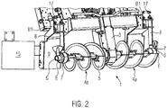
- Fig. 1 shows a road finisher 2 and Fig. 2 shows a transverse distributor arrangement 1 of a road paver 2.
- the transverse distributor arrangement 1 comprises one in the direction of travel of the road paver distribution auger 4a arranged on the right and a distribution auger 4b arranged on the left.
- Both distribution screws 4a, 4b are mounted centrally on a center console 3 and each extend from the center console 3 to outer end regions E.
- a screw drive (not shown) for driving the two distribution screws 4a, 4b.
- Each distribution screw 4a, 4b has a basic shaft 6. This can be two individual shafts 6 or a common shaft 6.
- the outer end E of each base shaft 6 facing away from the center console 3 is supported in an external bearing 7.
- Each external bearing 7 is mounted at the lower end of an external bearing bracket 8 which, for. B. is fastened by means of a fastening plate 17 at a first fastening location B1.
- This fastening location B1 can be arranged on a structural element 9 of the road paver 2 that is stationary relative to the center console 3 or on a duct plate 15 which is attached to the structural element 9.
- either the distributor screw 4a arranged on the right, the distributor screw 4b arranged on the left or both distributor screws 4a, 4b can be widened.
- the outer bearing bracket 8 is detached from the first fastening location B1 on the structural element 9 or channel plate 15 and the outer bearing 7 is detached from the base shaft 6.
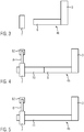
- Fig. 3 shows schematically the outer bearing 7 in its detached state from the base shaft 6.
- a widening shaft 10 is attached to the basic shaft. Furthermore, the outer bearing 7 is detachably mounted on the widening shaft 10 in its detached state from the base shaft 6 and the outer bearing bracket 8 is attached to a second fastening location B2 (see Fig. Fig. 4 ), which can be a location on the structural element 9 or the channel plate 15, is grown.
- Fig. 4 shows the outer bearing 7 in its detached state from the base shaft 6 and detachably mounted on the widening shaft 10.
- the outer bearing bracket 8 is now mounted at the second fastening location B2.
- the outer bearing 7 is alternatively detachably mounted in its detached state from the basic shaft 6 on a replacement basic shaft 11, which is longer or shorter than the basic shaft 6.
- Fig. 5 shows the outer bearing 7 in its detached state from the base shaft 6 and then already detachably mounted on the replacement base shaft 11.
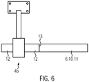
- Fig. 6 shows an embodiment of the invention in which an outer bearing 7 is rotatably mounted with transition wings 12.
- the transition wing 12 of the outer bearing 7 is detachably and non-rotatably mounted with a base shaft 6, a widening shaft 10 or a replacement base shaft 11.
- the releasable and non-rotatable connection between the transition wing and the shaft is made by means of connecting elements 13, for. B. screws or springs generated.
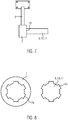
- Fig. 7 shows an alternative embodiment of the invention with an outer bearing 7 and with shafts 6, 10, 11 mounted thereon in a detachable connection without tools.
- Fig. 8 shows the spline profiles 14a, 14b of the outer bearing 7 and the shafts 6, 10, 11 in a front view.
- the outer bearing 7 has z. B. via a spline profile 14a, which is designed to be complementary to a second spline profile 14b of the basic shaft 6, the widening shaft 10 or the replacement basic shaft 11 at the respective end region E.
- the spline profiles 14a, 14b can have different tooth shapes, e.g. B. polygon or classic hexagon have.
- an axial lock 16 for. B. a locking ring be attached.
Landscapes
- Engineering & Computer Science (AREA)
- Architecture (AREA)
- Civil Engineering (AREA)
- Structural Engineering (AREA)
- Road Paving Machines (AREA)
- Mounting Of Bearings Or Others (AREA)
- Road Repair (AREA)
Priority Applications (7)
| Application Number | Priority Date | Filing Date | Title |
|---|---|---|---|
| EP19182531.4A EP3757290B1 (de) | 2019-06-26 | 2019-06-26 | Querverteileranordnung für einen strassenfertiger |
| PL19182531T PL3757290T3 (pl) | 2019-06-26 | 2019-06-26 | Układ rozdzielacza poprzecznego do wykańczarki |
| JP2020086459A JP7125962B2 (ja) | 2019-06-26 | 2020-05-18 | ロードフィニッシャ用の横送り装置、および横送り装置を組み立てる方法 |
| BR102020012342-4A BR102020012342B1 (pt) | 2019-06-26 | 2020-06-18 | Arranjo de distribuidor transversal, método de montagem de conjunto de distribuidor transversal e método de montagem de arranjo de distribuidor transversal |
| CN202021199125.9U CN212611813U (zh) | 2019-06-26 | 2020-06-24 | 用于道路整修机的横向分配器装置 |
| CN202010591629.3A CN112144348B (zh) | 2019-06-26 | 2020-06-24 | 用于道路整修机的横向分配器装置 |
| US16/911,532 US11313085B2 (en) | 2019-06-26 | 2020-06-25 | Transverse distributor arrangement for a road finisher |
Applications Claiming Priority (1)
| Application Number | Priority Date | Filing Date | Title |
|---|---|---|---|
| EP19182531.4A EP3757290B1 (de) | 2019-06-26 | 2019-06-26 | Querverteileranordnung für einen strassenfertiger |
Publications (2)
| Publication Number | Publication Date |
|---|---|
| EP3757290A1 EP3757290A1 (de) | 2020-12-30 |
| EP3757290B1 true EP3757290B1 (de) | 2021-06-02 |
Family
ID=67070736
Family Applications (1)
| Application Number | Title | Priority Date | Filing Date |
|---|---|---|---|
| EP19182531.4A Active EP3757290B1 (de) | 2019-06-26 | 2019-06-26 | Querverteileranordnung für einen strassenfertiger |
Country Status (5)
| Country | Link |
|---|---|
| US (1) | US11313085B2 (pl) |
| EP (1) | EP3757290B1 (pl) |
| JP (1) | JP7125962B2 (pl) |
| CN (2) | CN112144348B (pl) |
| PL (1) | PL3757290T3 (pl) |
Families Citing this family (1)
| Publication number | Priority date | Publication date | Assignee | Title |
|---|---|---|---|---|
| EP3757290B1 (de) * | 2019-06-26 | 2021-06-02 | Joseph Vögele AG | Querverteileranordnung für einen strassenfertiger |
Family Cites Families (21)
| Publication number | Priority date | Publication date | Assignee | Title |
|---|---|---|---|---|
| US4708519A (en) * | 1986-04-04 | 1987-11-24 | White Consolidated Industries, Inc. | Asphalt paving machine with liftable, adjustable auger mechanisms |
| US4749304A (en) * | 1986-09-15 | 1988-06-07 | White Consolidated Industries, Inc. | Variable width material distribution system for asphalt pavers and the like |
| US5354189A (en) * | 1992-12-30 | 1994-10-11 | Mckinnon Paul M | Curb forming and extruding apparatus |
| JP3382366B2 (ja) * | 1994-07-15 | 2003-03-04 | 有限会社きくや機械産業 | アスファルトフィニッシャーの合材送り用ねじ羽根の駆動側支持装置 |
| US5967427A (en) * | 1997-02-24 | 1999-10-19 | New Holland North America, Inc. | All purpose dual auger material spreader |
| JPH11262323A (ja) * | 1998-03-18 | 1999-09-28 | Kubota Corp | 脱穀装置の処理物搬送装置 |
| JP2000087308A (ja) * | 1998-09-16 | 2000-03-28 | Shin Caterpillar Mitsubishi Ltd | アスファルトフィニッシャ |
| EP1120495A1 (de) | 2000-01-25 | 2001-08-01 | Joseph Vögele AG | Strassenfertiger |
| JP2003232008A (ja) * | 2002-02-07 | 2003-08-19 | Nippon Hodo Co Ltd | アスファルトフィニッシャ |
| US7458747B2 (en) * | 2003-09-17 | 2008-12-02 | Cedarapids, Inc. | Frame raising multi-use paving tractor with blind mateable quick connecting tool attachments |
| US7381131B1 (en) * | 2006-07-19 | 2008-06-03 | Harpole Danny J | Extendable auger conveyor |
| US8322947B2 (en) * | 2010-06-11 | 2012-12-04 | Neumann Duane A | Flexible skid steer attachment device |
| DE202012003753U1 (de) | 2012-04-13 | 2013-07-17 | Joseph Vögele AG | Querverteilanordnung für einen Straßenfertiger |
| CN103498406B (zh) * | 2013-10-17 | 2015-07-29 | 陕西中大机械集团有限责任公司 | 摊铺机用折叠式螺旋输料机构 |
| CN204401416U (zh) * | 2014-12-18 | 2015-06-17 | 戴纳派克(中国)压实摊铺设备有限公司 | 螺旋轴调节装置及其摊铺机 |
| CN104480841B (zh) * | 2014-12-18 | 2016-06-29 | 戴纳派克(中国)压实摊铺设备有限公司 | 螺旋轴调节装置及其摊铺机 |
| CN104674632B (zh) * | 2015-03-20 | 2017-01-11 | 戴纳派克(中国)压实摊铺设备有限公司 | 带加热装置的螺旋分料器及其摊铺机 |
| US9932714B2 (en) * | 2016-04-27 | 2018-04-03 | Caterpillar Paving Products Inc. | Systems, apparatuses and methods for material flow control for wide-width paving |
| CN106087665B (zh) * | 2016-07-19 | 2018-08-17 | 徐州工程学院 | 一种用于伸缩熨平板的加宽联结装置及施工方法 |
| CN207712836U (zh) * | 2017-12-28 | 2018-08-10 | 陕西中大机械集团有限责任公司 | 一种摊铺机用螺旋输料轴 |
| EP3757290B1 (de) * | 2019-06-26 | 2021-06-02 | Joseph Vögele AG | Querverteileranordnung für einen strassenfertiger |
-
2019
- 2019-06-26 EP EP19182531.4A patent/EP3757290B1/de active Active
- 2019-06-26 PL PL19182531T patent/PL3757290T3/pl unknown
-
2020
- 2020-05-18 JP JP2020086459A patent/JP7125962B2/ja active Active
- 2020-06-24 CN CN202010591629.3A patent/CN112144348B/zh active Active
- 2020-06-24 CN CN202021199125.9U patent/CN212611813U/zh active Active
- 2020-06-25 US US16/911,532 patent/US11313085B2/en active Active
Also Published As
| Publication number | Publication date |
|---|---|
| CN112144348B (zh) | 2022-11-29 |
| CN212611813U (zh) | 2021-02-26 |
| CN112144348A (zh) | 2020-12-29 |
| EP3757290A1 (de) | 2020-12-30 |
| BR102020012342A2 (pt) | 2021-01-05 |
| US20200407926A1 (en) | 2020-12-31 |
| US11313085B2 (en) | 2022-04-26 |
| PL3757290T3 (pl) | 2021-11-08 |
| JP7125962B2 (ja) | 2022-08-25 |
| JP2021004544A (ja) | 2021-01-14 |
Similar Documents
| Publication | Publication Date | Title |
|---|---|---|
| EP2143531B1 (de) | System mit zwei verschiedenen Antriebswellen und mit einem Werkzeug mit einer Befestigungsöffnung zur formschlüssigen Verbindung mit den Antriebswellen | |
| DE102014007907B4 (de) | Abstreifeinrichtung mit einer Abstreiferleiste für eine Bodenfräsmaschine und Bodenfräsmaschine mit einer Abstreifeinrichtung | |
| EP3158851B1 (de) | Nockenriemen, insbesondere für landwirtschaftliche maschinen | |
| EP2903838B1 (de) | Lenkereinheit | |
| EP3105109B1 (de) | Breitenverstellbares modulares schwerlastfahrzeug und querrahmenmodul für ein derartiges schwerlastfahrzeug | |
| EP3757290B1 (de) | Querverteileranordnung für einen strassenfertiger | |
| DE69920076T2 (de) | Elastische Kupplung | |
| EP1650055A2 (de) | Antriebsbrücke | |
| EP2769938B1 (de) | Antriebswellenmodul für eine Baumaschine | |
| DE102007040046B4 (de) | Rotorshredder | |
| WO2012022789A1 (de) | Lageranordnung einer sattelkupplung | |
| DE2516082C2 (de) | Rinnenschuß für Kettenkratzförderer | |
| EP3157720B1 (de) | Fahrmischerpumpe | |
| EP3649841B1 (de) | Landwirtschaftliche maschine zur bodenbearbeitung | |
| DE102016211059A1 (de) | System zur Befestigung von Kühlermodulen mit mindestens einem Lagerzapfen in einem oberen Abschnitt eines Montageträger eines Kraftfahrzeuges sowie Zwischenelement für die Aufnahme eines Kühlerlagers eines Kühlermoduls | |
| WO2019015816A1 (de) | Antriebsrad für ein kettenlaufwerk eines kettenfahrzeugs | |
| EP3425122B1 (de) | Mehrteiliger adapter für ein vorsatzgerät | |
| EP3157721B1 (de) | Fahrmischerpumpe mit abstützeinrichtung | |
| EP3017109B1 (de) | Siebvorrichtung | |
| DE102011051088A1 (de) | Scharniergelenk zur Anwendung in Armen mit bis zu 180 Grad Zusammenfaltung der linearen Verbindungen zu Parallelführungen mittels eines oder mehrerer Gelenke | |
| DE19900839B4 (de) | Riegelelement | |
| DE10163968B4 (de) | Turasrad für ein Kettenlaufwerk | |
| DE102006039012B4 (de) | Verbindungsanordnung eines Querträgers an einem tragenden Bauteil eines Lastkraftwagens | |
| WO1993011988A1 (de) | Gelenkkupplung | |
| DE69925127T2 (de) | Geräteanschlussvorrichtung und -verfahren |
Legal Events
| Date | Code | Title | Description |
|---|---|---|---|
| PUAI | Public reference made under article 153(3) epc to a published international application that has entered the european phase |
Free format text: ORIGINAL CODE: 0009012 |
|
| STAA | Information on the status of an ep patent application or granted ep patent |
Free format text: STATUS: REQUEST FOR EXAMINATION WAS MADE |
|
| 17P | Request for examination filed |
Effective date: 20200513 |
|
| AK | Designated contracting states |
Kind code of ref document: A1 Designated state(s): AL AT BE BG CH CY CZ DE DK EE ES FI FR GB GR HR HU IE IS IT LI LT LU LV MC MK MT NL NO PL PT RO RS SE SI SK SM TR |
|
| AX | Request for extension of the european patent |
Extension state: BA ME |
|
| GRAP | Despatch of communication of intention to grant a patent |
Free format text: ORIGINAL CODE: EPIDOSNIGR1 |
|
| STAA | Information on the status of an ep patent application or granted ep patent |
Free format text: STATUS: GRANT OF PATENT IS INTENDED |
|
| INTG | Intention to grant announced |
Effective date: 20210312 |
|
| RIN1 | Information on inventor provided before grant (corrected) |
Inventor name: OETTINGER, KLAUS |
|
| GRAS | Grant fee paid |
Free format text: ORIGINAL CODE: EPIDOSNIGR3 |
|
| GRAA | (expected) grant |
Free format text: ORIGINAL CODE: 0009210 |
|
| STAA | Information on the status of an ep patent application or granted ep patent |
Free format text: STATUS: THE PATENT HAS BEEN GRANTED |
|
| REG | Reference to a national code |
Ref country code: CH Ref legal event code: EP |
|
| AK | Designated contracting states |
Kind code of ref document: B1 Designated state(s): AL AT BE BG CH CY CZ DE DK EE ES FI FR GB GR HR HU IE IS IT LI LT LU LV MC MK MT NL NO PL PT RO RS SE SI SK SM TR |
|
| REG | Reference to a national code |
Ref country code: GB Ref legal event code: FG4D Free format text: NOT ENGLISH |
|
| REG | Reference to a national code |
Ref country code: AT Ref legal event code: REF Ref document number: 1398532 Country of ref document: AT Kind code of ref document: T Effective date: 20210615 |
|
| REG | Reference to a national code |
Ref country code: IE Ref legal event code: FG4D Free format text: LANGUAGE OF EP DOCUMENT: GERMAN |
|
| REG | Reference to a national code |
Ref country code: DE Ref legal event code: R096 Ref document number: 502019001533 Country of ref document: DE |
|
| REG | Reference to a national code |
Ref country code: LT Ref legal event code: MG9D |
|
| PG25 | Lapsed in a contracting state [announced via postgrant information from national office to epo] |
Ref country code: BG Free format text: LAPSE BECAUSE OF FAILURE TO SUBMIT A TRANSLATION OF THE DESCRIPTION OR TO PAY THE FEE WITHIN THE PRESCRIBED TIME-LIMIT Effective date: 20210902 Ref country code: LT Free format text: LAPSE BECAUSE OF FAILURE TO SUBMIT A TRANSLATION OF THE DESCRIPTION OR TO PAY THE FEE WITHIN THE PRESCRIBED TIME-LIMIT Effective date: 20210602 Ref country code: HR Free format text: LAPSE BECAUSE OF FAILURE TO SUBMIT A TRANSLATION OF THE DESCRIPTION OR TO PAY THE FEE WITHIN THE PRESCRIBED TIME-LIMIT Effective date: 20210602 Ref country code: FI Free format text: LAPSE BECAUSE OF FAILURE TO SUBMIT A TRANSLATION OF THE DESCRIPTION OR TO PAY THE FEE WITHIN THE PRESCRIBED TIME-LIMIT Effective date: 20210602 |
|
| REG | Reference to a national code |
Ref country code: NL Ref legal event code: MP Effective date: 20210602 |
|
| PG25 | Lapsed in a contracting state [announced via postgrant information from national office to epo] |
Ref country code: GR Free format text: LAPSE BECAUSE OF FAILURE TO SUBMIT A TRANSLATION OF THE DESCRIPTION OR TO PAY THE FEE WITHIN THE PRESCRIBED TIME-LIMIT Effective date: 20210903 Ref country code: LV Free format text: LAPSE BECAUSE OF FAILURE TO SUBMIT A TRANSLATION OF THE DESCRIPTION OR TO PAY THE FEE WITHIN THE PRESCRIBED TIME-LIMIT Effective date: 20210602 Ref country code: NO Free format text: LAPSE BECAUSE OF FAILURE TO SUBMIT A TRANSLATION OF THE DESCRIPTION OR TO PAY THE FEE WITHIN THE PRESCRIBED TIME-LIMIT Effective date: 20210902 Ref country code: RS Free format text: LAPSE BECAUSE OF FAILURE TO SUBMIT A TRANSLATION OF THE DESCRIPTION OR TO PAY THE FEE WITHIN THE PRESCRIBED TIME-LIMIT Effective date: 20210602 Ref country code: SE Free format text: LAPSE BECAUSE OF FAILURE TO SUBMIT A TRANSLATION OF THE DESCRIPTION OR TO PAY THE FEE WITHIN THE PRESCRIBED TIME-LIMIT Effective date: 20210602 |
|
| PG25 | Lapsed in a contracting state [announced via postgrant information from national office to epo] |
Ref country code: SM Free format text: LAPSE BECAUSE OF FAILURE TO SUBMIT A TRANSLATION OF THE DESCRIPTION OR TO PAY THE FEE WITHIN THE PRESCRIBED TIME-LIMIT Effective date: 20210602 Ref country code: RO Free format text: LAPSE BECAUSE OF FAILURE TO SUBMIT A TRANSLATION OF THE DESCRIPTION OR TO PAY THE FEE WITHIN THE PRESCRIBED TIME-LIMIT Effective date: 20210602 Ref country code: NL Free format text: LAPSE BECAUSE OF FAILURE TO SUBMIT A TRANSLATION OF THE DESCRIPTION OR TO PAY THE FEE WITHIN THE PRESCRIBED TIME-LIMIT Effective date: 20210602 Ref country code: PT Free format text: LAPSE BECAUSE OF FAILURE TO SUBMIT A TRANSLATION OF THE DESCRIPTION OR TO PAY THE FEE WITHIN THE PRESCRIBED TIME-LIMIT Effective date: 20211004 Ref country code: CZ Free format text: LAPSE BECAUSE OF FAILURE TO SUBMIT A TRANSLATION OF THE DESCRIPTION OR TO PAY THE FEE WITHIN THE PRESCRIBED TIME-LIMIT Effective date: 20210602 Ref country code: SK Free format text: LAPSE BECAUSE OF FAILURE TO SUBMIT A TRANSLATION OF THE DESCRIPTION OR TO PAY THE FEE WITHIN THE PRESCRIBED TIME-LIMIT Effective date: 20210602 Ref country code: ES Free format text: LAPSE BECAUSE OF FAILURE TO SUBMIT A TRANSLATION OF THE DESCRIPTION OR TO PAY THE FEE WITHIN THE PRESCRIBED TIME-LIMIT Effective date: 20210602 Ref country code: EE Free format text: LAPSE BECAUSE OF FAILURE TO SUBMIT A TRANSLATION OF THE DESCRIPTION OR TO PAY THE FEE WITHIN THE PRESCRIBED TIME-LIMIT Effective date: 20210602 |
|
| REG | Reference to a national code |
Ref country code: DE Ref legal event code: R097 Ref document number: 502019001533 Country of ref document: DE |
|
| REG | Reference to a national code |
Ref country code: BE Ref legal event code: MM Effective date: 20210630 |
|
| PG25 | Lapsed in a contracting state [announced via postgrant information from national office to epo] |
Ref country code: MC Free format text: LAPSE BECAUSE OF FAILURE TO SUBMIT A TRANSLATION OF THE DESCRIPTION OR TO PAY THE FEE WITHIN THE PRESCRIBED TIME-LIMIT Effective date: 20210602 Ref country code: LU Free format text: LAPSE BECAUSE OF NON-PAYMENT OF DUE FEES Effective date: 20210626 |
|
| PLBE | No opposition filed within time limit |
Free format text: ORIGINAL CODE: 0009261 |
|
| STAA | Information on the status of an ep patent application or granted ep patent |
Free format text: STATUS: NO OPPOSITION FILED WITHIN TIME LIMIT |
|
| PG25 | Lapsed in a contracting state [announced via postgrant information from national office to epo] |
Ref country code: IE Free format text: LAPSE BECAUSE OF NON-PAYMENT OF DUE FEES Effective date: 20210626 Ref country code: DK Free format text: LAPSE BECAUSE OF FAILURE TO SUBMIT A TRANSLATION OF THE DESCRIPTION OR TO PAY THE FEE WITHIN THE PRESCRIBED TIME-LIMIT Effective date: 20210602 |
|
| 26N | No opposition filed |
Effective date: 20220303 |
|
| PG25 | Lapsed in a contracting state [announced via postgrant information from national office to epo] |
Ref country code: AL Free format text: LAPSE BECAUSE OF FAILURE TO SUBMIT A TRANSLATION OF THE DESCRIPTION OR TO PAY THE FEE WITHIN THE PRESCRIBED TIME-LIMIT Effective date: 20210602 |
|
| PG25 | Lapsed in a contracting state [announced via postgrant information from national office to epo] |
Ref country code: BE Free format text: LAPSE BECAUSE OF NON-PAYMENT OF DUE FEES Effective date: 20210630 |
|
| REG | Reference to a national code |
Ref country code: CH Ref legal event code: PL |
|
| PG25 | Lapsed in a contracting state [announced via postgrant information from national office to epo] |
Ref country code: LI Free format text: LAPSE BECAUSE OF NON-PAYMENT OF DUE FEES Effective date: 20220630 Ref country code: CH Free format text: LAPSE BECAUSE OF NON-PAYMENT OF DUE FEES Effective date: 20220630 |
|
| P01 | Opt-out of the competence of the unified patent court (upc) registered |
Effective date: 20230524 |
|
| PG25 | Lapsed in a contracting state [announced via postgrant information from national office to epo] |
Ref country code: CY Free format text: LAPSE BECAUSE OF FAILURE TO SUBMIT A TRANSLATION OF THE DESCRIPTION OR TO PAY THE FEE WITHIN THE PRESCRIBED TIME-LIMIT Effective date: 20210602 |
|
| PG25 | Lapsed in a contracting state [announced via postgrant information from national office to epo] |
Ref country code: HU Free format text: LAPSE BECAUSE OF FAILURE TO SUBMIT A TRANSLATION OF THE DESCRIPTION OR TO PAY THE FEE WITHIN THE PRESCRIBED TIME-LIMIT; INVALID AB INITIO Effective date: 20190626 |
|
| PG25 | Lapsed in a contracting state [announced via postgrant information from national office to epo] |
Ref country code: MK Free format text: LAPSE BECAUSE OF FAILURE TO SUBMIT A TRANSLATION OF THE DESCRIPTION OR TO PAY THE FEE WITHIN THE PRESCRIBED TIME-LIMIT Effective date: 20210602 |
|
| PG25 | Lapsed in a contracting state [announced via postgrant information from national office to epo] |
Ref country code: MT Free format text: LAPSE BECAUSE OF FAILURE TO SUBMIT A TRANSLATION OF THE DESCRIPTION OR TO PAY THE FEE WITHIN THE PRESCRIBED TIME-LIMIT Effective date: 20210602 |
|
| PGFP | Annual fee paid to national office [announced via postgrant information from national office to epo] |
Ref country code: PL Payment date: 20250611 Year of fee payment: 7 Ref country code: DE Payment date: 20250626 Year of fee payment: 7 |
|
| PGFP | Annual fee paid to national office [announced via postgrant information from national office to epo] |
Ref country code: GB Payment date: 20250621 Year of fee payment: 7 |
|
| PGFP | Annual fee paid to national office [announced via postgrant information from national office to epo] |
Ref country code: FR Payment date: 20250617 Year of fee payment: 7 |
|
| REG | Reference to a national code |
Ref country code: AT Ref legal event code: MM01 Ref document number: 1398532 Country of ref document: AT Kind code of ref document: T Effective date: 20240626 |
|
| PGFP | Annual fee paid to national office [announced via postgrant information from national office to epo] |
Ref country code: IT Payment date: 20250627 Year of fee payment: 7 |
|
| PG25 | Lapsed in a contracting state [announced via postgrant information from national office to epo] |
Ref country code: AT Free format text: LAPSE BECAUSE OF NON-PAYMENT OF DUE FEES Effective date: 20240626 |
|
| PG25 | Lapsed in a contracting state [announced via postgrant information from national office to epo] |
Ref country code: TR Free format text: LAPSE BECAUSE OF FAILURE TO SUBMIT A TRANSLATION OF THE DESCRIPTION OR TO PAY THE FEE WITHIN THE PRESCRIBED TIME-LIMIT Effective date: 20210602 |
|
| PGFP | Annual fee paid to national office [announced via postgrant information from national office to epo] |
Ref country code: AT Payment date: 20260410 Year of fee payment: 5 |