EP3757290B1 - Longitudinal distribution assembly for a paver - Google Patents
Longitudinal distribution assembly for a paver Download PDFInfo
- Publication number
- EP3757290B1 EP3757290B1 EP19182531.4A EP19182531A EP3757290B1 EP 3757290 B1 EP3757290 B1 EP 3757290B1 EP 19182531 A EP19182531 A EP 19182531A EP 3757290 B1 EP3757290 B1 EP 3757290B1
- Authority
- EP
- European Patent Office
- Prior art keywords
- outer bearing
- base shaft
- shaft
- attachment point
- extending
- Prior art date
- Legal status (The legal status is an assumption and is not a legal conclusion. Google has not performed a legal analysis and makes no representation as to the accuracy of the status listed.)
- Active
Links
- 238000000034 method Methods 0.000 claims description 12
- 230000007704 transition Effects 0.000 claims description 10
- 230000000295 complement effect Effects 0.000 claims description 3
- 238000006243 chemical reaction Methods 0.000 description 3
- 238000010276 construction Methods 0.000 description 2
- 230000008878 coupling Effects 0.000 description 1
- 238000010168 coupling process Methods 0.000 description 1
- 238000005859 coupling reaction Methods 0.000 description 1
Images

Classifications
-
- E—FIXED CONSTRUCTIONS
- E01—CONSTRUCTION OF ROADS, RAILWAYS, OR BRIDGES
- E01C—CONSTRUCTION OF, OR SURFACES FOR, ROADS, SPORTS GROUNDS, OR THE LIKE; MACHINES OR AUXILIARY TOOLS FOR CONSTRUCTION OR REPAIR
- E01C19/00—Machines, tools or auxiliary devices for preparing or distributing paving materials, for working the placed materials, or for forming, consolidating, or finishing the paving
- E01C19/12—Machines, tools or auxiliary devices for preparing or distributing paving materials, for working the placed materials, or for forming, consolidating, or finishing the paving for distributing granular or liquid materials
- E01C19/20—Apparatus for distributing, e.g. spreading, granular or pulverulent materials, e.g. sand, gravel, salt, dry binders
- E01C19/201—Apparatus for distributing, e.g. spreading, granular or pulverulent materials, e.g. sand, gravel, salt, dry binders with driven loosening, discharging or spreading parts, e.g. power-driven, drive derived from road-wheels
- E01C19/202—Apparatus for distributing, e.g. spreading, granular or pulverulent materials, e.g. sand, gravel, salt, dry binders with driven loosening, discharging or spreading parts, e.g. power-driven, drive derived from road-wheels solely rotating, e.g. discharging and spreading drums
-
- E—FIXED CONSTRUCTIONS
- E01—CONSTRUCTION OF ROADS, RAILWAYS, OR BRIDGES
- E01C—CONSTRUCTION OF, OR SURFACES FOR, ROADS, SPORTS GROUNDS, OR THE LIKE; MACHINES OR AUXILIARY TOOLS FOR CONSTRUCTION OR REPAIR
- E01C19/00—Machines, tools or auxiliary devices for preparing or distributing paving materials, for working the placed materials, or for forming, consolidating, or finishing the paving
- E01C19/48—Machines, tools or auxiliary devices for preparing or distributing paving materials, for working the placed materials, or for forming, consolidating, or finishing the paving for laying-down the materials and consolidating them, or finishing the surface, e.g. slip forms therefor, forming kerbs or gutters in a continuous operation in situ
-
- E—FIXED CONSTRUCTIONS
- E01—CONSTRUCTION OF ROADS, RAILWAYS, OR BRIDGES
- E01C—CONSTRUCTION OF, OR SURFACES FOR, ROADS, SPORTS GROUNDS, OR THE LIKE; MACHINES OR AUXILIARY TOOLS FOR CONSTRUCTION OR REPAIR
- E01C2301/00—Machine characteristics, parts or accessories not otherwise provided for
- E01C2301/02—Feeding devices for pavers
Definitions
- the present invention relates to a transverse distributor arrangement for a road finisher according to the preamble of claim 1.
- Cross manifold arrangements are, for example, from EP 1 120 495 A1 and EP 2 650 442 B1 known. They are attached to the rear end of the paver finisher's chassis, namely between the chassis and a screed towed by the tractor. Paving material, for example bituminous paving mix, is conveyed to the transverse distributor arrangement by means of a longitudinal conveyor, also called a scraper belt. This has the task of distributing the paving mix in the transverse direction of the paver so that the paving material is available over the entire width of the subsequent paving screed.
- the transverse distributor arrangement typically has two distributor screws, namely a left and a right distributor screw. Each distribution screw has a basic shaft. Because of the considerable forces, the outer ends of the basic shafts are usually not freely supported, but in each case in an external bearing which is fastened to the chassis of the road paver by means of an external bearing bracket.
- the document JP H08 277 22 A relates to a road finisher with a support device for a screw wing.
- the distribution auger must also be lengthened in order to ensure that the mix is distributed over the entire width.
- this is solved either by widening shafts with external bearings that are attached to the base shaft of the distribution auger.
- the basic shaft is dismantled and replaced by a replacement shaft with a different length than the basic shaft and with its own external bearing.
- there are several bearings in the mix after the widening assembly which makes it difficult to circulate the paving material.
- the rebuilding effort and storage are considerable, since each shaft has "its" external bearing already mounted, which is usually permanently mounted on the shaft by means of a press fit.
- the object of the present invention is therefore to provide an improved construction for transverse distributor arrangements for road pavers and a method for assembling such transverse distributor arrangements in order to eliminate the disadvantages listed above.
- the transverse distributor arrangement for a road finisher provides a center console and counter-rotating augers, the augers each with screw elements fastened thereon and a base shaft extending from the center console to outer end regions.
- the base shaft is mounted in an external bearing, the external bearing being mountable at a fastening location via an external bearing bracket.
- a widening shaft can be attached to the fundamental shaft or the fundamental shaft can be exchanged for a replacement fundamental shaft with a different length than the fundamental shaft.
- the basic shaft and the outer bearing are detachably connected to one another, the same outer bearing being detachably mountable on the widening shaft or on the replacement basic shaft in its detached state from the basic shaft.
- transverse distributor arrangement for a road paver is the reduction in the number of different components in the storage.
- the components are easier to handle. This simplifies the conversion for the distribution auger extensions.
- the design of the transverse distributor arrangement according to the invention reduces the number of external bearings that are located in the mix, as a result of which the flow of material is improved.
- the respective first or second fastening location can be arranged on a structural element of the road paver that is stationary relative to the center console or on a duct plate that is attached to the structural element.
- the first / second fastening locations of the external bearing bracket differ from one another, but are each stationary relative to the tractor of the road paver, in particular relative to the center console.
- the outer bearing can comprise one or more transition wings.
- a transition wing enables the outer bearing to be connected to the shafts.
- Two transition wings make it possible to connect the outer bearing to the shafts on one side of the outer bearing and to add additional components, such as screw elements, to the other side of the outer bearing.
- a transition wing of the outer bearing can expediently be mounted with the basic shaft or the widening shaft or the replacement basic shaft via one or more connecting elements.
- the outer bearing can be mounted with the basic shaft or with the widening shaft or with the replacement basic shaft in a connection that can be detached without tools. This makes it possible to reduce the work involved in converting the widening of the distribution auger and the Amount of fastening material required for the conversion, e.g. B. screws to reduce and thereby save time.
- the tool-free detachable connection between the outer bearing and the shaft can be achieved in particular with a toothed coupling, the outer bearing having a spline profile, while the basic shaft, the widening shaft and the replacement basic shaft have a different spline profile that is complementary to the spline profile of the outer bearing.
- the invention further relates to a method for assembling a transverse distributor arrangement for a road paver, in which the outer bearing bracket is first detached from a first fastening location and the outer bearing is detached from the base shaft. Furthermore, a widening shaft is attached to the basic shaft, the outer bearing bracket being attached to a second fastening location and the outer bearing being releasably attached to the widening shaft.
- the outer bearing bracket is preferably released from a first fastening location, which can be arranged on a structural element of the road paver that is stationary relative to the center console or on a duct plate that is attached to the structural element.
- the outer bearing bracket is preferably attached to a second fastening location, which can be arranged on a structural element of the road paver that is stationary relative to the center console or on a duct plate which is attached to the structural element.
- the outer bearing bracket is detached from a first fastening location of the structural element and the outer bearing is detached from a base shaft. Furthermore, the fundamental wave is replaced by a replacement fundamental wave which has a different length than the fundamental wave. Finally, the outer bearing bracket is attached to a second fastening location and the outer bearing is releasably fastened to the replacement base shaft.
- the outer bearing bracket is preferably released from a first fastening location, which can be arranged on a structural element of the road paver that is stationary relative to the center console or on a duct plate that is attached to the structural element.
- the outer bearing bracket is preferably attached to a second fastening location, which can be arranged on a structural element of the road paver that is stationary relative to the center console or on a duct plate which is attached to the structural element.
- the second attachment point can be arranged on a channel plate, the channel plate z. B. is grown on the structural element.
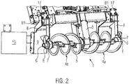
- Fig. 1 shows a road finisher 2 and Fig. 2 shows a transverse distributor arrangement 1 of a road paver 2.
- the transverse distributor arrangement 1 comprises one in the direction of travel of the road paver distribution auger 4a arranged on the right and a distribution auger 4b arranged on the left.
- Both distribution screws 4a, 4b are mounted centrally on a center console 3 and each extend from the center console 3 to outer end regions E.
- a screw drive (not shown) for driving the two distribution screws 4a, 4b.
- Each distribution screw 4a, 4b has a basic shaft 6. This can be two individual shafts 6 or a common shaft 6.
- the outer end E of each base shaft 6 facing away from the center console 3 is supported in an external bearing 7.
- Each external bearing 7 is mounted at the lower end of an external bearing bracket 8 which, for. B. is fastened by means of a fastening plate 17 at a first fastening location B1.
- This fastening location B1 can be arranged on a structural element 9 of the road paver 2 that is stationary relative to the center console 3 or on a duct plate 15 which is attached to the structural element 9.
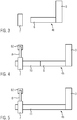
- either the distributor screw 4a arranged on the right, the distributor screw 4b arranged on the left or both distributor screws 4a, 4b can be widened.
- the outer bearing bracket 8 is detached from the first fastening location B1 on the structural element 9 or channel plate 15 and the outer bearing 7 is detached from the base shaft 6.
- Fig. 3 shows schematically the outer bearing 7 in its detached state from the base shaft 6.
- a widening shaft 10 is attached to the basic shaft. Furthermore, the outer bearing 7 is detachably mounted on the widening shaft 10 in its detached state from the base shaft 6 and the outer bearing bracket 8 is attached to a second fastening location B2 (see Fig. Fig. 4 ), which can be a location on the structural element 9 or the channel plate 15, is grown.
- Fig. 4 shows the outer bearing 7 in its detached state from the base shaft 6 and detachably mounted on the widening shaft 10.
- the outer bearing bracket 8 is now mounted at the second fastening location B2.
- the outer bearing 7 is alternatively detachably mounted in its detached state from the basic shaft 6 on a replacement basic shaft 11, which is longer or shorter than the basic shaft 6.
- Fig. 5 shows the outer bearing 7 in its detached state from the base shaft 6 and then already detachably mounted on the replacement base shaft 11.
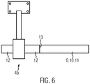
- Fig. 6 shows an embodiment of the invention in which an outer bearing 7 is rotatably mounted with transition wings 12.
- the transition wing 12 of the outer bearing 7 is detachably and non-rotatably mounted with a base shaft 6, a widening shaft 10 or a replacement base shaft 11.
- the releasable and non-rotatable connection between the transition wing and the shaft is made by means of connecting elements 13, for. B. screws or springs generated.
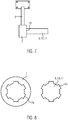
- Fig. 7 shows an alternative embodiment of the invention with an outer bearing 7 and with shafts 6, 10, 11 mounted thereon in a detachable connection without tools.
- Fig. 8 shows the spline profiles 14a, 14b of the outer bearing 7 and the shafts 6, 10, 11 in a front view.
- the outer bearing 7 has z. B. via a spline profile 14a, which is designed to be complementary to a second spline profile 14b of the basic shaft 6, the widening shaft 10 or the replacement basic shaft 11 at the respective end region E.
- the spline profiles 14a, 14b can have different tooth shapes, e.g. B. polygon or classic hexagon have.
- an axial lock 16 for. B. a locking ring be attached.
Landscapes
- Engineering & Computer Science (AREA)
- Architecture (AREA)
- Civil Engineering (AREA)
- Structural Engineering (AREA)
- Road Paving Machines (AREA)
- Mounting Of Bearings Or Others (AREA)
- Road Repair (AREA)
Description
Die vorliegende Erfindung betrifft eine Querverteileranordnung für einen Straßenfertiger gemäß dem Oberbegriff des Anspruchs 1.The present invention relates to a transverse distributor arrangement for a road finisher according to the preamble of claim 1.
Querverteileranordnungen sind beispielsweise aus der
Das Dokument
Wird heute eine große Arbeitsbreite der Bohle benötigt, so muss auch die Verteilerschnecke verlängert werden, um die Verteilung des Mischguts über die gesamte Breite zu gewährleisten. Dies wird bei großen Arbeitsbereichen entweder durch Verbreiterungswellen mit Außenlagern gelöst, die an der Grundwelle der Verteilerschnecke angebaut werden. Oder die Grundwelle wird demontiert und durch eine Ersatzwelle mit anderer Länge als die Grundwelle und mit eigenem Außenlager ersetzt. Im ersteren Fall befinden sich nach der Verbreiterungsmontage mehrere Lager im Mischgut, was das Umwälzen des Einbaumaterials erschwert. Darüber hinaus sind der Umbauaufwand und die Lagerhaltung hierbei beträchtlich, da jede Welle "ihr" Außenlager schon montiert mitbringt, welches meistens mittels Presspassung unlösbar an der Welle montiert ist.If a large working width of the screed is required today, the distribution auger must also be lengthened in order to ensure that the mix is distributed over the entire width. In the case of large work areas, this is solved either by widening shafts with external bearings that are attached to the base shaft of the distribution auger. Or the basic shaft is dismantled and replaced by a replacement shaft with a different length than the basic shaft and with its own external bearing. In the first case, there are several bearings in the mix after the widening assembly, which makes it difficult to circulate the paving material. In addition, the rebuilding effort and storage are considerable, since each shaft has "its" external bearing already mounted, which is usually permanently mounted on the shaft by means of a press fit.
Aufgabe der vorliegenden Erfindung ist es demzufolge, eine verbesserte Bauweise für Querverteileranordnungen für Straßenfertiger und ein Verfahren zur Montage solcher Querverteileranordnungen zur Verfügung zu stellen, um die oben aufgeführten Nachteile zu beseitigen.The object of the present invention is therefore to provide an improved construction for transverse distributor arrangements for road pavers and a method for assembling such transverse distributor arrangements in order to eliminate the disadvantages listed above.
Diese Aufgabe wird gelöst durch eine modulare Querverteileranordnung für einen Straßenfertiger mit den Merkmalen des Anspruchs 1 oder durch ein Verfahren zur Montage von Querverteileranordnungen für einen Straßenfertiger mit den Merkmalen eines der Ansprüche 8 oder 10.This object is achieved by a modular transverse distributor arrangement for a road paver with the features of claim 1 or by a method for assembling transverse distributor arrangements for a road finisher with the features of one of
Bevorzugte Ausführungsformen der Erfindung sind in den Unteransprüchen angegeben.Preferred embodiments of the invention are specified in the subclaims.
Die Querverteileranordnung für einen Straßenfertiger sieht eine Mittelkonsole und gegenläufige Verteilerschnecken vor, wobei die Verteilerschnecken sich jeweils mit darauf befestigten Schneckenelementen und einer Grundwelle von der Mittelkonsole heraus zu äußeren Endbereichen erstrecken. Die Grundwelle ist in einem Außenlager gelagert, wobei das Außenlager über eine Außenlagerkonsole an einem Befestigungsort montierbar ist. Eine Verbreiterungswelle ist an die Grundwelle anbaubar oder die Grundwelle ist gegen eine Ersatzgrundwelle mit anderer Länge als die Grundwelle austauschbar. Erfindungsgemäß sind die Grundwelle und das Außenlager lösbar miteinander verbunden, wobei dasselbe Außenlager in seinem von der Grundwelle gelösten Zustand lösbar auf der Verbreiterungswelle oder auf der Ersatzgrundwelle montierbar ist.The transverse distributor arrangement for a road finisher provides a center console and counter-rotating augers, the augers each with screw elements fastened thereon and a base shaft extending from the center console to outer end regions. The base shaft is mounted in an external bearing, the external bearing being mountable at a fastening location via an external bearing bracket. A widening shaft can be attached to the fundamental shaft or the fundamental shaft can be exchanged for a replacement fundamental shaft with a different length than the fundamental shaft. According to the invention, the basic shaft and the outer bearing are detachably connected to one another, the same outer bearing being detachably mountable on the widening shaft or on the replacement basic shaft in its detached state from the basic shaft.
Ein Vorteil dieses modularen Konzepts für die Bauweise der Querverteileranordnung für einen Straßenfertiger ist die Reduktion der Anzahl von verschiedenen Bauteilen in der Lagerung. Zudem sind die Bauteile einfacher zu handhaben. Dies vereinfacht den Umbau für die Verteilerschneckenverbreiterungen. Darüber hinaus reduziert die erfindungsgemäße Bauweise der Querverteileranordnung die Anzahl der Außenlager, welche sich im Mischgut befinden, wodurch der Materialfluss verbessert wird.One advantage of this modular concept for the construction of the transverse distributor arrangement for a road paver is the reduction in the number of different components in the storage. In addition, the components are easier to handle. This simplifies the conversion for the distribution auger extensions. In addition, the design of the transverse distributor arrangement according to the invention reduces the number of external bearings that are located in the mix, as a result of which the flow of material is improved.
Der jeweilige erste oder zweite Befestigungsort kann auf einem relativ zur Mittelkonsole ortsfesten Strukturelement des Straßenfertigers oder auf einem Kanalblech, das an dem Strukturelement angebaut ist, angeordnet sein.The respective first or second fastening location can be arranged on a structural element of the road paver that is stationary relative to the center console or on a duct plate that is attached to the structural element.
Die ersten/zweiten Befestigungsorte der Außenlagerkonsole unterscheiden sich voneinander, sind aber jeweils ortsfest relativ zur Zugmaschine des Straßenfertigers, insbesondere relativ zur Mittelkonsole.The first / second fastening locations of the external bearing bracket differ from one another, but are each stationary relative to the tractor of the road paver, in particular relative to the center console.
Insbesondere kann das Außenlager einen oder mehrere Übergangsflügel umfassen. Ein Übergangsflügel ermöglicht es, das Außenlager mit den Wellen zu verbinden. Zwei Übergangsflügel ermöglichen auf einer Seite des Außenlagers, das Außenlager mit den Wellen zu verbinden, und auf der anderen Seite des Außenlagers weitere Bauelemente, wie beispielsweise Schneckenelemente, anzubauen.In particular, the outer bearing can comprise one or more transition wings. A transition wing enables the outer bearing to be connected to the shafts. Two transition wings make it possible to connect the outer bearing to the shafts on one side of the outer bearing and to add additional components, such as screw elements, to the other side of the outer bearing.
Zweckmäßig ist ein Übergangsflügel des Außenlagers mit der Grundwelle oder der Verbreiterungswelle oder der Ersatzgrundwelle über ein oder mehrere Verbindungselemente montierbar.A transition wing of the outer bearing can expediently be mounted with the basic shaft or the widening shaft or the replacement basic shaft via one or more connecting elements.
Besonders vorteilhaft ist es, wenn das Außenlager mit der Grundwelle oder mit der Verbreiterungswelle oder mit der Ersatzgrundwelle in einer werkzeuglos lösbaren Verbindung montierbar ist. Dies ermöglicht es, den Umbauaufwand für die Verteilerschneckenverbreiterungen und die Menge des beim Umbau benötigtem Befestigungsmaterials, z. B. Schrauben, zu reduzieren und dadurch Zeit einzusparen.It is particularly advantageous if the outer bearing can be mounted with the basic shaft or with the widening shaft or with the replacement basic shaft in a connection that can be detached without tools. This makes it possible to reduce the work involved in converting the widening of the distribution auger and the Amount of fastening material required for the conversion, e.g. B. screws to reduce and thereby save time.
Die werkzeuglos lösbare Verbindung zwischen dem Außenlager und der Welle kann insbesondere mit einer Zahnkupplung erreicht werden, wobei das Außenlager ein Passverzahnungsprofil aufweist, während die Grundwelle, die Verbreiterungswelle und die Ersatzgrundwelle ein anderes, zu dem Passverzahnungsprofil des Außenlagers komplementäres Passverzahnungsprofil aufweisen.The tool-free detachable connection between the outer bearing and the shaft can be achieved in particular with a toothed coupling, the outer bearing having a spline profile, while the basic shaft, the widening shaft and the replacement basic shaft have a different spline profile that is complementary to the spline profile of the outer bearing.
Besonders betriebssicher ist es, die werkzeuglos lösbare Verbindung zwischen dem Außenlager und der Grundwelle oder der Verbreiterungswelle oder der Ersatzgrundwelle zu sichern, indem die Grundwelle oder die Verbreiterungswelle oder die Ersatzgrundwelle mit dem Außenlager axial gesichert ist.It is particularly reliable to secure the tool-free detachable connection between the outer bearing and the basic shaft or the widening shaft or the replacement basic shaft by axially securing the basic shaft or the widening shaft or the replacement basic shaft with the outer bearing.
Die Erfindung betrifft weiterhin ein Verfahren zur Montage einer Querverteileranordnung für einen Straßenfertiger, bei dem zunächst die Außenlagerkonsole von einem ersten Befestigungsort sowie das Außenlager von der Grundwelle gelöst werden. Des Weiteren wird eine Verbreiterungswelle an der Grundwelle angebaut, wobei die Außenlagerkonsole an einem zweiten Befestigungsort angebaut und das Außenlager an der Verbreiterungswelle lösbar befestigt wird.The invention further relates to a method for assembling a transverse distributor arrangement for a road paver, in which the outer bearing bracket is first detached from a first fastening location and the outer bearing is detached from the base shaft. Furthermore, a widening shaft is attached to the basic shaft, the outer bearing bracket being attached to a second fastening location and the outer bearing being releasably attached to the widening shaft.
Die Außenlagerkonsole wird vorzugsweise von einem ersten Befestigungsort gelöst, der auf einem relativ zur Mittelkonsole ortsfesten Strukturelement des Straßenfertigers oder auf einem Kanalblech, das an dem Strukturelement angebaut ist, angeordnet werden kann.The outer bearing bracket is preferably released from a first fastening location, which can be arranged on a structural element of the road paver that is stationary relative to the center console or on a duct plate that is attached to the structural element.
Die Außenlagerkonsole wird vorzugsweise an einem zweiten Befestigungsort angebaut, der auf einem relativ zur Mittelkonsole ortsfesten Strukturelement des Straßenfertigers oder auf einem Kanalblech, das an dem Strukturelement angebaut ist, angeordnet werden kann.The outer bearing bracket is preferably attached to a second fastening location, which can be arranged on a structural element of the road paver that is stationary relative to the center console or on a duct plate which is attached to the structural element.
Zweckmäßig wird eine axiale Sicherung zwischen der Grundwelle und dem Außenlager gelöst und die Verbreiterungswelle wird an dem Außenlager axial gesichert.An axial securing between the basic shaft and the outer bearing is expediently released and the widening shaft is axially secured to the outer bearing.
Bei einem anderen alternativen erfindungsgemäßen Verfahren zur Montage einer Querverteileranordnung für einen Straßenfertiger wird die Außenlagerkonsole von einem ersten Befestigungsort des Strukturelements und das Außenlager von einer Grundwelle gelöst. Des Weiteren wird die Grundwelle durch eine Ersatzgrundwelle ersetzt, welche eine andere Länge als die Grundwelle aufweist. Schließlich wird die Außenlagerkonsole an einem zweiten Befestigungsort angebaut und das Außenlager an der Ersatzgrundwelle lösbar befestigt.In another alternative method according to the invention for assembling a transverse distributor arrangement for a road paver, the outer bearing bracket is detached from a first fastening location of the structural element and the outer bearing is detached from a base shaft. Furthermore, the fundamental wave is replaced by a replacement fundamental wave which has a different length than the fundamental wave. Finally, the outer bearing bracket is attached to a second fastening location and the outer bearing is releasably fastened to the replacement base shaft.
Zweckmäßig wird eine axiale Sicherung zwischen der Grundwelle und dem Außenlager gelöst und die Ersatzgrundwelle wird an dem Außenlager axial gesichert.An axial securing between the basic shaft and the outer bearing is expediently released and the replacement basic shaft is axially secured to the outer bearing.
Die Außenlagerkonsole wird vorzugsweise von einem ersten Befestigungsort gelöst, der auf einem relativ zur Mittelkonsole ortsfesten Strukturelement des Straßenfertigers oder auf einem Kanalblech, das an dem Strukturelement angebaut ist, angeordnet werden kann.The outer bearing bracket is preferably released from a first fastening location, which can be arranged on a structural element of the road paver that is stationary relative to the center console or on a duct plate that is attached to the structural element.
Die Außenlagerkonsole wird bevorzugt an einem zweiten Befestigungsort angebaut, der auf einem relativ zur Mittelkonsole ortsfesten Strukturelement des Straßenfertigers oder auf einem Kanalblech, das an dem Strukturelement angebaut ist, angeordnet werden kann.The outer bearing bracket is preferably attached to a second fastening location, which can be arranged on a structural element of the road paver that is stationary relative to the center console or on a duct plate which is attached to the structural element.
Alternativ kann der zweite Befestigungsort an einem Kanalblech angeordnet sein, wobei das Kanalblech z. B. an dem Strukturelement angebaut ist.Alternatively, the second attachment point can be arranged on a channel plate, the channel plate z. B. is grown on the structural element.
Im Folgenden werden beispielhafte Ausführungsformen anhand der Figuren näher erläutert.
- Figur 1
- zeigt eine schematische Perspektivansicht eines Straßenfertigers.
Figur 2- zeigt eine schematische Perspektivansicht einer Querverteileranordnung.
Figur 3- zeigt eine schematische Vorderansicht der Querverteileranordnung aus
Fig. 2 . - Figur 4
- zeigt eine schematische Vorderansicht der Querverteileranordnung aus
Fig. 2 in einem erweiterten Zustand. Figur 5- zeigt eine schematische Vorderansicht der Querverteileranordnung aus
Fig. 2 in einem anderen erweiterten Zustand.; - Figur 6
- zeigt eine schematische Vorderansicht einer Ausführungsform der Erfindung, in der ein Außenlager mit Übergangsflügeln angebaut ist.
Figur 7- zeigt eine schematische Vorderansicht einer alternativen Ausführungsform der Erfindung, in der ein Außenlager mit den Wellen werkzeuglos lösbar verbunden und zu diesen axial gesichert ist.
Figur 8- zeigt eine schematische Seitenansicht des Außenlagers und der Wellen aus
Fig. 7 mit deren Passverzahnungsprofilen.
- Figure 1
- shows a schematic perspective view of a road finisher.
- Figure 2
- Figure 11 shows a schematic perspective view of a transverse manifold arrangement.
- Figure 3
- FIG. 13 shows a schematic front view of the transverse manifold arrangement from FIG
Fig. 2 . - Figure 4
- FIG. 13 shows a schematic front view of the transverse manifold arrangement from FIG
Fig. 2 in an expanded state. - Figure 5
- FIG. 13 shows a schematic front view of the transverse manifold arrangement from FIG
Fig. 2 in another expanded state .; - Figure 6
- shows a schematic front view of an embodiment of the invention in which an outer bearing with transition wings is added.
- Figure 7
- shows a schematic front view of an alternative embodiment of the invention, in which an outer bearing is detachably connected to the shafts without tools and axially secured to them.
- Figure 8
- FIG. 11 shows a schematic side view of the outer bearing and the shafts from FIG
Fig. 7 with their spline profiles.
Jede Verteilerschnecke 4a, 4b verfügt über eine Grundwelle 6. Dabei kann es sich um zwei einzelne Wellen 6 oder eine gemeinsame Welle 6 handeln. Das äußere, von der Mittelkonsole 3 abgewandte Ende E jeder Grundwelle 6 ist in einem Außenlager 7 gelagert. Jedes Außenlager 7 ist am unteren Ende einer Außenlagerkonsole 8 montiert, welche z. B. mittels einer Befestigungsplatte 17 an einem ersten Befestigungsort B1 befestigt ist. Dieser Befestigungsort B1 kann auf einem relativ zur Mittelkonsole 3 ortsfesten Strukturelement 9 des Straßenfertigers 2 oder auf einem Kanalblech 15, das an dem Strukturelement 9 angebaut ist, angeordnet sein.Each
Um die Querverteileranordnung 1 für verschiedene Arbeitsbreiten umzubauen, können entweder die rechts angeordnete Verteilerschnecke 4a, die links angeordnete Verteilerschnecke 4b oder beide Verteilerschnecken 4a, 4b verbreitert werden. Dafür werden die Außenlagerkonsole 8 von dem ersten Befestigungsort B1 am Strukturelement 9 oder Kanalblech 15 und das Außenlager 7 von der Grundwelle 6 gelöst.In order to convert the transverse distributor arrangement 1 for different working widths, either the
Für den Umbau der Querverteileranordnung 1 für unterschiedliche Arbeitsbreiten wird eine Verbreiterungswelle 10 an der Grundwelle angebaut. Weiterhin wird das Außenlager 7 in seinem von der Grundwelle 6 gelösten Zustand auf der Verbreiterungswelle 10 lösbar montiert und die Außenlagerkonsole 8 an einem zweiten Befestigungsort B2 (s.
Für den Umbau der Querverteileranordnung 1 für unterschiedliche Arbeitsbreiten wird alternativ das Außenlager 7 in seinem von der Grundwelle 6 gelösten Zustand auf einer Ersatzgrundwelle 11, die länger oder kurzer als die Grundwelle 6 ist, lösbar montiert.For the conversion of the transverse distributor arrangement 1 for different working widths, the
Um die werkzeuglos lösbare Verbindung zwischen dem Außenlager 7 und den Wellen 6, 10, 11 zu sichern, kann eine axiale Sicherung 16, z. B. ein Sicherungsring, angebracht sein.To secure the tool-free releasable connection between the
Claims (13)
- Transverse distributor arrangement (1) for a road finisher (2), comprising a centre console (3) and augers (4a, 4b) extending in opposite directions, the augers (4a, 4b) each having auger elements (5) mounted thereon and a base shaft (6) extending from the centre console (3) to the outer end region (E), wherein the base shaft (6) is mounted in an outer bearing (7), wherein the outer bearing (7) can be mounted at a first attachment point (B1) via an outer bearing bracket (8), wherein a extending shaft (10) can be fitted to the base shaft (6) or the base shaft (6) can be replaced by a replacement base shaft (11) of a different length than the base shaft (6),
characterised in that
the outer bearing (7) is detachable from the first attachment point (B1) via an outer bearing bracket (8) and attachable to a second attachment point (B2), wherein the base shaft (6) and the outer bearing (7) are detachably connected to each other, wherein the outer bearing (7) in its state detached from the base shaft (6) can be mounted detachably on the extending shaft (10) or on the replacement base shaft (11). - Transverse distributor arrangement according to claim 1, characterised in that the first and second attachment point (B1, B2) is arranged on a structural element (9) of the road finisher (2) which is stationary relative to the centre console (3) or on a limiting plate (15) which is attached to the structural element (9).
- Transverse distributor arrangement according to claim 1 or 2, characterised in that the outer bearing (7) comprises one or more transition wings (12).
- Transverse distributor arrangement according to claim 3, characterised in that a transition wing (12) of the outer bearing (7) is mountable with the base shaft (6) or the extending shaft (10) or the replacement base shaft (11) via one or more connecting elements (13).
- Transverse distributor arrangement according to one of the preceding claims, characterised in that the outer bearing (7) can be mounted with the base shaft (6) or with the extending shaft (10) or with the replacement base shaft (11) in a connection which can be released without tools.
- Transverse distributor assembly according to one of the preceding claims, characterised in that the outer bearing (7) has a spline profile (14a), the base shaft (6) and the extending shaft (10) and the replacement base shaft (11) having another spline profile (14b) complementary to the spline profile (14a) of the outer bearing.
- Transverse distributor arrangement according to one of the preceding claims, characterised in that the base shaft (6) or the extending shaft (10) or the replacement base shaft (11) is axially secured with the outer bearing (7).
- A method of assembling a transverse distributor assembly (1) for a road finisher (2), the method comprising
detaching an outer bearing bracket (8) of an outer bearing (7) from a first attachment point (B1),
detaching the outer bearing (7) from a base shaft (6) of an auger,
mounting a extending shaft (10) to the base shaft (6),
mounting the outer bearing bracket (8) at a second attachment point (B2), detachably attaching the outer bearing (7) to the extending shaft (10). - A method according to claim 8, which further comprising:detaching an axial securing device (16) between the base shaft (6) and the outer bearing (7),axially securing the extending shaft (10) on the outer bearing (7).
- A method of assembling a transverse distributor arrangement (1) for a road finisher (2), the method comprising
detaching an outer bearing bracket (8) of an outer bearing (7) from a first attachment point (B1),
detaching the outer bearing (7) from a base shaft (6) of an auger,
replacing the base shaft (6) by a replacement base shaft (11) which has a different length than the base shaft (6),
mounting the outer bearing bracket (8) at a second attachment point (B2), detachably attaching the outer bearing (7) to the replacement base shaft (11). - A method according to claim 10, further comprising:
detaching an axial securing (16) between the base shaft (6) and the outer bearing (7), axially securing the replacement base shaft (11) on the outer bearing (7). - A method according to one of claims 8 to 11, further comprising detaching the outer bearing bracket (8) from the first attachment point (B1), which is arranged on a structural element (9) of the road finisher (2) that is stationary relative to the centre console (3) or on a limiting plate (15) that is attached to the structural element (9).
- A method according to one of claims 8 to 12, further comprising mounting the outer bearing bracket (8) on the second attachment point (B2), which is arranged on a structural element (9) of the road finisher (2) that is stationary relative to the centre console (3) or on a limiting plate (15) that is mounted on the structural element (9).
Priority Applications (7)
| Application Number | Priority Date | Filing Date | Title |
|---|---|---|---|
| PL19182531T PL3757290T3 (en) | 2019-06-26 | 2019-06-26 | Longitudinal distribution assembly for a paver |
| EP19182531.4A EP3757290B1 (en) | 2019-06-26 | 2019-06-26 | Longitudinal distribution assembly for a paver |
| JP2020086459A JP7125962B2 (en) | 2019-06-26 | 2020-05-18 | Traverse feeder for road finisher and method of assembling the traverse feeder |
| BR102020012342-4A BR102020012342B1 (en) | 2019-06-26 | 2020-06-18 | TRANSVERSE DISTRIBUTOR ARRANGEMENT, METHOD OF ASSEMBLY OF TRANSVERSE DISTRIBUTOR ASSEMBLY AND METHOD OF ASSEMBLY OF TRANSVERSE DISTRIBUTOR ARRANGEMENT |
| CN202010591629.3A CN112144348B (en) | 2019-06-26 | 2020-06-24 | Transverse distributor device for a road finishing machine |
| CN202021199125.9U CN212611813U (en) | 2019-06-26 | 2020-06-24 | Transverse distributor device for a road finishing machine |
| US16/911,532 US11313085B2 (en) | 2019-06-26 | 2020-06-25 | Transverse distributor arrangement for a road finisher |
Applications Claiming Priority (1)
| Application Number | Priority Date | Filing Date | Title |
|---|---|---|---|
| EP19182531.4A EP3757290B1 (en) | 2019-06-26 | 2019-06-26 | Longitudinal distribution assembly for a paver |
Publications (2)
| Publication Number | Publication Date |
|---|---|
| EP3757290A1 EP3757290A1 (en) | 2020-12-30 |
| EP3757290B1 true EP3757290B1 (en) | 2021-06-02 |
Family
ID=67070736
Family Applications (1)
| Application Number | Title | Priority Date | Filing Date |
|---|---|---|---|
| EP19182531.4A Active EP3757290B1 (en) | 2019-06-26 | 2019-06-26 | Longitudinal distribution assembly for a paver |
Country Status (5)
| Country | Link |
|---|---|
| US (1) | US11313085B2 (en) |
| EP (1) | EP3757290B1 (en) |
| JP (1) | JP7125962B2 (en) |
| CN (2) | CN112144348B (en) |
| PL (1) | PL3757290T3 (en) |
Families Citing this family (1)
| Publication number | Priority date | Publication date | Assignee | Title |
|---|---|---|---|---|
| PL3757290T3 (en) * | 2019-06-26 | 2021-11-08 | Joseph Vögele AG | Longitudinal distribution assembly for a paver |
Family Cites Families (21)
| Publication number | Priority date | Publication date | Assignee | Title |
|---|---|---|---|---|
| US4708519A (en) * | 1986-04-04 | 1987-11-24 | White Consolidated Industries, Inc. | Asphalt paving machine with liftable, adjustable auger mechanisms |
| US4749304A (en) * | 1986-09-15 | 1988-06-07 | White Consolidated Industries, Inc. | Variable width material distribution system for asphalt pavers and the like |
| US5354189A (en) * | 1992-12-30 | 1994-10-11 | Mckinnon Paul M | Curb forming and extruding apparatus |
| JP3382366B2 (en) * | 1994-07-15 | 2003-03-04 | 有限会社きくや機械産業 | Driving side support device for screw blade for asphalt finisher |
| US5967427A (en) * | 1997-02-24 | 1999-10-19 | New Holland North America, Inc. | All purpose dual auger material spreader |
| JPH11262323A (en) * | 1998-03-18 | 1999-09-28 | Kubota Corp | Conveyor for treated material of threshing device |
| JP2000087308A (en) * | 1998-09-16 | 2000-03-28 | Shin Caterpillar Mitsubishi Ltd | Asphalt finisher |
| EP1120495A1 (en) | 2000-01-25 | 2001-08-01 | Joseph Vögele AG | Paver |
| JP2003232008A (en) * | 2002-02-07 | 2003-08-19 | Nippon Hodo Co Ltd | Asphalt finisher |
| US7458747B2 (en) * | 2003-09-17 | 2008-12-02 | Cedarapids, Inc. | Frame raising multi-use paving tractor with blind mateable quick connecting tool attachments |
| US7381131B1 (en) * | 2006-07-19 | 2008-06-03 | Harpole Danny J | Extendable auger conveyor |
| US8322947B2 (en) * | 2010-06-11 | 2012-12-04 | Neumann Duane A | Flexible skid steer attachment device |
| DE202012003753U1 (en) | 2012-04-13 | 2013-07-17 | Joseph Vögele AG | Cross distribution arrangement for a paver |
| CN103498406B (en) * | 2013-10-17 | 2015-07-29 | 陕西中大机械集团有限责任公司 | Foldable spiral delivery mechanism for paver |
| CN204401416U (en) * | 2014-12-18 | 2015-06-17 | 戴纳派克(中国)压实摊铺设备有限公司 | Helical axis adjusting device and paver thereof |
| CN104480841B (en) * | 2014-12-18 | 2016-06-29 | 戴纳派克(中国)压实摊铺设备有限公司 | Spiral axis adjustment device and paver thereof |
| CN104674632B (en) * | 2015-03-20 | 2017-01-11 | 戴纳派克(中国)压实摊铺设备有限公司 | Screw material distributor with heating device and paver of screw material distributor |
| US9932714B2 (en) * | 2016-04-27 | 2018-04-03 | Caterpillar Paving Products Inc. | Systems, apparatuses and methods for material flow control for wide-width paving |
| CN106087665B (en) * | 2016-07-19 | 2018-08-17 | 徐州工程学院 | It is a kind of to widen hookup and construction method for freely-moving mangle |
| CN207712836U (en) * | 2017-12-28 | 2018-08-10 | 陕西中大机械集团有限责任公司 | A kind of paver spiral feeding shaft |
| PL3757290T3 (en) * | 2019-06-26 | 2021-11-08 | Joseph Vögele AG | Longitudinal distribution assembly for a paver |
-
2019
- 2019-06-26 PL PL19182531T patent/PL3757290T3/en unknown
- 2019-06-26 EP EP19182531.4A patent/EP3757290B1/en active Active
-
2020
- 2020-05-18 JP JP2020086459A patent/JP7125962B2/en active Active
- 2020-06-24 CN CN202010591629.3A patent/CN112144348B/en active Active
- 2020-06-24 CN CN202021199125.9U patent/CN212611813U/en active Active
- 2020-06-25 US US16/911,532 patent/US11313085B2/en active Active
Also Published As
| Publication number | Publication date |
|---|---|
| CN212611813U (en) | 2021-02-26 |
| EP3757290A1 (en) | 2020-12-30 |
| US11313085B2 (en) | 2022-04-26 |
| CN112144348A (en) | 2020-12-29 |
| JP7125962B2 (en) | 2022-08-25 |
| CN112144348B (en) | 2022-11-29 |
| US20200407926A1 (en) | 2020-12-31 |
| BR102020012342A2 (en) | 2021-01-05 |
| JP2021004544A (en) | 2021-01-14 |
| PL3757290T3 (en) | 2021-11-08 |
Similar Documents
| Publication | Publication Date | Title |
|---|---|---|
| EP2143531B1 (en) | System with two different drive shafts and with a tool with an attachment opening for form-fit connection with the drive shafts | |
| EP3158851B1 (en) | Toothed belt, in particular for agricultural machines | |
| DE102014007907B4 (en) | Scraper device with a scraper bar for a floor milling machine and floor milling machine with a scraper device | |
| EP2903838B1 (en) | Steering unit | |
| EP3105109B1 (en) | Width-adjustable modular heavy goods vehicle, and transverse frame module for a heavy goods vehicle of said type | |
| EP1650055A2 (en) | Driving bridge | |
| EP3757290B1 (en) | Longitudinal distribution assembly for a paver | |
| EP2769938B1 (en) | Drive shaft module for a construction machine | |
| DE69920076T2 (en) | Elastic coupling | |
| WO2012022789A1 (en) | Bearing assembly of a fifth wheel coupling | |
| DE2516082C2 (en) | Channel section for chain scraper conveyor | |
| DE102007040046B4 (en) | Rotorshredder | |
| DE102016211059A1 (en) | System for mounting radiator modules with at least one journal in an upper portion of a mounting bracket of a motor vehicle and intermediate element for receiving a radiator bearing of a radiator module | |
| DE102008056919B4 (en) | Suspension for a vibrating functional part, in particular for an exhaust system of a motor vehicle | |
| DE102012012615A1 (en) | Ejector for a mobile tillage machine | |
| EP3157720B1 (en) | Truck mixer concrete pump | |
| EP3157721B1 (en) | Truck mixer pump comprising a supporting device | |
| EP3330110A1 (en) | Bearing block for fixing a beam axle longitudinal arm with component affecting operating load case | |
| EP3362603A1 (en) | Skid segment for an edge protection on a road milling machine and edge protection for a road milling machine | |
| EP3017109B1 (en) | Screening device | |
| DE102006039012B4 (en) | Connecting arrangement of a cross member to a load-bearing component of a truck | |
| DE19900839B4 (en) | locking element | |
| EP3425122B1 (en) | Multi-part adapter for a header | |
| WO2019015816A1 (en) | Drive wheel for a track drive of a tracked vehicle | |
| DE10163968B4 (en) | Turasrad for a chain drive |
Legal Events
| Date | Code | Title | Description |
|---|---|---|---|
| PUAI | Public reference made under article 153(3) epc to a published international application that has entered the european phase |
Free format text: ORIGINAL CODE: 0009012 |
|
| STAA | Information on the status of an ep patent application or granted ep patent |
Free format text: STATUS: REQUEST FOR EXAMINATION WAS MADE |
|
| 17P | Request for examination filed |
Effective date: 20200513 |
|
| AK | Designated contracting states |
Kind code of ref document: A1 Designated state(s): AL AT BE BG CH CY CZ DE DK EE ES FI FR GB GR HR HU IE IS IT LI LT LU LV MC MK MT NL NO PL PT RO RS SE SI SK SM TR |
|
| AX | Request for extension of the european patent |
Extension state: BA ME |
|
| GRAP | Despatch of communication of intention to grant a patent |
Free format text: ORIGINAL CODE: EPIDOSNIGR1 |
|
| STAA | Information on the status of an ep patent application or granted ep patent |
Free format text: STATUS: GRANT OF PATENT IS INTENDED |
|
| INTG | Intention to grant announced |
Effective date: 20210312 |
|
| RIN1 | Information on inventor provided before grant (corrected) |
Inventor name: OETTINGER, KLAUS |
|
| GRAS | Grant fee paid |
Free format text: ORIGINAL CODE: EPIDOSNIGR3 |
|
| GRAA | (expected) grant |
Free format text: ORIGINAL CODE: 0009210 |
|
| STAA | Information on the status of an ep patent application or granted ep patent |
Free format text: STATUS: THE PATENT HAS BEEN GRANTED |
|
| REG | Reference to a national code |
Ref country code: CH Ref legal event code: EP |
|
| AK | Designated contracting states |
Kind code of ref document: B1 Designated state(s): AL AT BE BG CH CY CZ DE DK EE ES FI FR GB GR HR HU IE IS IT LI LT LU LV MC MK MT NL NO PL PT RO RS SE SI SK SM TR |
|
| REG | Reference to a national code |
Ref country code: GB Ref legal event code: FG4D Free format text: NOT ENGLISH |
|
| REG | Reference to a national code |
Ref country code: AT Ref legal event code: REF Ref document number: 1398532 Country of ref document: AT Kind code of ref document: T Effective date: 20210615 |
|
| REG | Reference to a national code |
Ref country code: IE Ref legal event code: FG4D Free format text: LANGUAGE OF EP DOCUMENT: GERMAN |
|
| REG | Reference to a national code |
Ref country code: DE Ref legal event code: R096 Ref document number: 502019001533 Country of ref document: DE |
|
| REG | Reference to a national code |
Ref country code: LT Ref legal event code: MG9D |
|
| PG25 | Lapsed in a contracting state [announced via postgrant information from national office to epo] |
Ref country code: BG Free format text: LAPSE BECAUSE OF FAILURE TO SUBMIT A TRANSLATION OF THE DESCRIPTION OR TO PAY THE FEE WITHIN THE PRESCRIBED TIME-LIMIT Effective date: 20210902 Ref country code: LT Free format text: LAPSE BECAUSE OF FAILURE TO SUBMIT A TRANSLATION OF THE DESCRIPTION OR TO PAY THE FEE WITHIN THE PRESCRIBED TIME-LIMIT Effective date: 20210602 Ref country code: HR Free format text: LAPSE BECAUSE OF FAILURE TO SUBMIT A TRANSLATION OF THE DESCRIPTION OR TO PAY THE FEE WITHIN THE PRESCRIBED TIME-LIMIT Effective date: 20210602 Ref country code: FI Free format text: LAPSE BECAUSE OF FAILURE TO SUBMIT A TRANSLATION OF THE DESCRIPTION OR TO PAY THE FEE WITHIN THE PRESCRIBED TIME-LIMIT Effective date: 20210602 |
|
| REG | Reference to a national code |
Ref country code: NL Ref legal event code: MP Effective date: 20210602 |
|
| PG25 | Lapsed in a contracting state [announced via postgrant information from national office to epo] |
Ref country code: GR Free format text: LAPSE BECAUSE OF FAILURE TO SUBMIT A TRANSLATION OF THE DESCRIPTION OR TO PAY THE FEE WITHIN THE PRESCRIBED TIME-LIMIT Effective date: 20210903 Ref country code: LV Free format text: LAPSE BECAUSE OF FAILURE TO SUBMIT A TRANSLATION OF THE DESCRIPTION OR TO PAY THE FEE WITHIN THE PRESCRIBED TIME-LIMIT Effective date: 20210602 Ref country code: NO Free format text: LAPSE BECAUSE OF FAILURE TO SUBMIT A TRANSLATION OF THE DESCRIPTION OR TO PAY THE FEE WITHIN THE PRESCRIBED TIME-LIMIT Effective date: 20210902 Ref country code: RS Free format text: LAPSE BECAUSE OF FAILURE TO SUBMIT A TRANSLATION OF THE DESCRIPTION OR TO PAY THE FEE WITHIN THE PRESCRIBED TIME-LIMIT Effective date: 20210602 Ref country code: SE Free format text: LAPSE BECAUSE OF FAILURE TO SUBMIT A TRANSLATION OF THE DESCRIPTION OR TO PAY THE FEE WITHIN THE PRESCRIBED TIME-LIMIT Effective date: 20210602 |
|
| PG25 | Lapsed in a contracting state [announced via postgrant information from national office to epo] |
Ref country code: SM Free format text: LAPSE BECAUSE OF FAILURE TO SUBMIT A TRANSLATION OF THE DESCRIPTION OR TO PAY THE FEE WITHIN THE PRESCRIBED TIME-LIMIT Effective date: 20210602 Ref country code: RO Free format text: LAPSE BECAUSE OF FAILURE TO SUBMIT A TRANSLATION OF THE DESCRIPTION OR TO PAY THE FEE WITHIN THE PRESCRIBED TIME-LIMIT Effective date: 20210602 Ref country code: NL Free format text: LAPSE BECAUSE OF FAILURE TO SUBMIT A TRANSLATION OF THE DESCRIPTION OR TO PAY THE FEE WITHIN THE PRESCRIBED TIME-LIMIT Effective date: 20210602 Ref country code: PT Free format text: LAPSE BECAUSE OF FAILURE TO SUBMIT A TRANSLATION OF THE DESCRIPTION OR TO PAY THE FEE WITHIN THE PRESCRIBED TIME-LIMIT Effective date: 20211004 Ref country code: CZ Free format text: LAPSE BECAUSE OF FAILURE TO SUBMIT A TRANSLATION OF THE DESCRIPTION OR TO PAY THE FEE WITHIN THE PRESCRIBED TIME-LIMIT Effective date: 20210602 Ref country code: SK Free format text: LAPSE BECAUSE OF FAILURE TO SUBMIT A TRANSLATION OF THE DESCRIPTION OR TO PAY THE FEE WITHIN THE PRESCRIBED TIME-LIMIT Effective date: 20210602 Ref country code: ES Free format text: LAPSE BECAUSE OF FAILURE TO SUBMIT A TRANSLATION OF THE DESCRIPTION OR TO PAY THE FEE WITHIN THE PRESCRIBED TIME-LIMIT Effective date: 20210602 Ref country code: EE Free format text: LAPSE BECAUSE OF FAILURE TO SUBMIT A TRANSLATION OF THE DESCRIPTION OR TO PAY THE FEE WITHIN THE PRESCRIBED TIME-LIMIT Effective date: 20210602 |
|
| REG | Reference to a national code |
Ref country code: DE Ref legal event code: R097 Ref document number: 502019001533 Country of ref document: DE |
|
| REG | Reference to a national code |
Ref country code: BE Ref legal event code: MM Effective date: 20210630 |
|
| PG25 | Lapsed in a contracting state [announced via postgrant information from national office to epo] |
Ref country code: MC Free format text: LAPSE BECAUSE OF FAILURE TO SUBMIT A TRANSLATION OF THE DESCRIPTION OR TO PAY THE FEE WITHIN THE PRESCRIBED TIME-LIMIT Effective date: 20210602 Ref country code: LU Free format text: LAPSE BECAUSE OF NON-PAYMENT OF DUE FEES Effective date: 20210626 |
|
| PLBE | No opposition filed within time limit |
Free format text: ORIGINAL CODE: 0009261 |
|
| STAA | Information on the status of an ep patent application or granted ep patent |
Free format text: STATUS: NO OPPOSITION FILED WITHIN TIME LIMIT |
|
| PG25 | Lapsed in a contracting state [announced via postgrant information from national office to epo] |
Ref country code: IE Free format text: LAPSE BECAUSE OF NON-PAYMENT OF DUE FEES Effective date: 20210626 Ref country code: DK Free format text: LAPSE BECAUSE OF FAILURE TO SUBMIT A TRANSLATION OF THE DESCRIPTION OR TO PAY THE FEE WITHIN THE PRESCRIBED TIME-LIMIT Effective date: 20210602 |
|
| 26N | No opposition filed |
Effective date: 20220303 |
|
| PG25 | Lapsed in a contracting state [announced via postgrant information from national office to epo] |
Ref country code: AL Free format text: LAPSE BECAUSE OF FAILURE TO SUBMIT A TRANSLATION OF THE DESCRIPTION OR TO PAY THE FEE WITHIN THE PRESCRIBED TIME-LIMIT Effective date: 20210602 |
|
| PG25 | Lapsed in a contracting state [announced via postgrant information from national office to epo] |
Ref country code: BE Free format text: LAPSE BECAUSE OF NON-PAYMENT OF DUE FEES Effective date: 20210630 |
|
| REG | Reference to a national code |
Ref country code: CH Ref legal event code: PL |
|
| PG25 | Lapsed in a contracting state [announced via postgrant information from national office to epo] |
Ref country code: LI Free format text: LAPSE BECAUSE OF NON-PAYMENT OF DUE FEES Effective date: 20220630 Ref country code: CH Free format text: LAPSE BECAUSE OF NON-PAYMENT OF DUE FEES Effective date: 20220630 |
|
| P01 | Opt-out of the competence of the unified patent court (upc) registered |
Effective date: 20230524 |
|
| PG25 | Lapsed in a contracting state [announced via postgrant information from national office to epo] |
Ref country code: CY Free format text: LAPSE BECAUSE OF FAILURE TO SUBMIT A TRANSLATION OF THE DESCRIPTION OR TO PAY THE FEE WITHIN THE PRESCRIBED TIME-LIMIT Effective date: 20210602 |
|
| PG25 | Lapsed in a contracting state [announced via postgrant information from national office to epo] |
Ref country code: HU Free format text: LAPSE BECAUSE OF FAILURE TO SUBMIT A TRANSLATION OF THE DESCRIPTION OR TO PAY THE FEE WITHIN THE PRESCRIBED TIME-LIMIT; INVALID AB INITIO Effective date: 20190626 |
|
| PGFP | Annual fee paid to national office [announced via postgrant information from national office to epo] |
Ref country code: IT Payment date: 20230629 Year of fee payment: 5 |
|
| PG25 | Lapsed in a contracting state [announced via postgrant information from national office to epo] |
Ref country code: MK Free format text: LAPSE BECAUSE OF FAILURE TO SUBMIT A TRANSLATION OF THE DESCRIPTION OR TO PAY THE FEE WITHIN THE PRESCRIBED TIME-LIMIT Effective date: 20210602 |
|
| PGFP | Annual fee paid to national office [announced via postgrant information from national office to epo] |
Ref country code: GB Payment date: 20240625 Year of fee payment: 6 |
|
| PGFP | Annual fee paid to national office [announced via postgrant information from national office to epo] |
Ref country code: DE Payment date: 20240626 Year of fee payment: 6 |
|
| PGFP | Annual fee paid to national office [announced via postgrant information from national office to epo] |
Ref country code: FR Payment date: 20240626 Year of fee payment: 6 |
|
| PGFP | Annual fee paid to national office [announced via postgrant information from national office to epo] |
Ref country code: PL Payment date: 20240606 Year of fee payment: 6 |