EP3757272A1 - Manschette für ein wäschebehandlungsgerät, wäschebehandlungsgerät und verfahren zum einstellen eines spaltmasses - Google Patents
Manschette für ein wäschebehandlungsgerät, wäschebehandlungsgerät und verfahren zum einstellen eines spaltmasses Download PDFInfo
- Publication number
- EP3757272A1 EP3757272A1 EP20179062.3A EP20179062A EP3757272A1 EP 3757272 A1 EP3757272 A1 EP 3757272A1 EP 20179062 A EP20179062 A EP 20179062A EP 3757272 A1 EP3757272 A1 EP 3757272A1
- Authority
- EP
- European Patent Office
- Prior art keywords
- cuff
- cavity
- laundry drum
- tub
- functional surface
- Prior art date
- Legal status (The legal status is an assumption and is not a legal conclusion. Google has not performed a legal analysis and makes no representation as to the accuracy of the status listed.)
- Granted
Links
Images

Classifications
-
- D—TEXTILES; PAPER
- D06—TREATMENT OF TEXTILES OR THE LIKE; LAUNDERING; FLEXIBLE MATERIALS NOT OTHERWISE PROVIDED FOR
- D06F—LAUNDERING, DRYING, IRONING, PRESSING OR FOLDING TEXTILE ARTICLES
- D06F37/00—Details specific to washing machines covered by groups D06F21/00 - D06F25/00
- D06F37/26—Casings; Tubs
- D06F37/261—Tubs made by a specially selected manufacturing process or characterised by their assembly from elements
- D06F37/263—Tubs made by a specially selected manufacturing process or characterised by their assembly from elements assembled from at least two elements connected to each other; Connecting or sealing means therefor
-
- D—TEXTILES; PAPER
- D06—TREATMENT OF TEXTILES OR THE LIKE; LAUNDERING; FLEXIBLE MATERIALS NOT OTHERWISE PROVIDED FOR
- D06F—LAUNDERING, DRYING, IRONING, PRESSING OR FOLDING TEXTILE ARTICLES
- D06F37/00—Details specific to washing machines covered by groups D06F21/00 - D06F25/00
- D06F37/26—Casings; Tubs
- D06F37/266—Gaskets mounted between tub and casing around the loading opening
Definitions
- the invention relates to a cuff according to the preamble of claim 1, a laundry treatment device according to the preamble of claim 7 and a method for setting a gap between a functional surface of a cuff of a laundry treatment device and a surface of a laundry drum facing this functional surface.
- the invention relates in particular to a laundry treatment device in which the laundry is fed in at the front through an essentially axial loading channel through a closable loading opening formed in the housing of the laundry treatment device.
- Such laundry treatment devices are also referred to as front loaders.
- laundry treatment device is understood to mean both a classic washing machine and a so-called washer-dryer which combines the functions of a washing machine and a clothes dryer.
- a cuff for a laundry treatment device and a laundry treatment device of the type mentioned at the beginning are based on the German Offenlegungsschrift DE 10 2015 216 363 A1 which describes a front-loading washing machine with a washing machine housing, a tub received in the housing and mounted so as to be movable in a swinging manner relative to this, and a laundry drum arranged therein to be rotatable.
- the laundry drum has a front side in which a loading opening aligned with its axis of rotation is provided. This charging opening is in turn surrounded by a concentric through-opening in the end face of the tub, which is aligned with a charging opening on the housing side.
- the feed opening on the housing side and the through-opening of the tub are connected by a hose-like cuff which allows the tubing to oscillate relative to the housing.
- the cuff forms a liquid-tight feed channel through which laundry can be introduced into the laundry drum or removed from it.
- the cuff has a cuff end on the tub side, which is liquid-tight and firmly connected to the tub around the through opening of the tub.
- a section or area of the cuff has a circumferential side that functions as a functional surface.
- the functional surface In the installed position, the functional surface is positioned with the formation of a gap in relation to a surface of the laundry drum front facing it. This surface can be formed by the edge which delimits the loading opening in the laundry drum front. This edge can be designed as a fold or bead.
- the bellows has a fold formed approximately in its middle length region and formed approximately S-shaped in longitudinal section, the S-bend of which on the outside forms a circumferential functional surface, close to the longitudinal axis.
- the functional surface is at a distance from an edge of the front side of the laundry drum surrounding the loading opening, an at least partially elastomeric extension protruding radially into the space existing between the fold and the edge.
- the extension serves to prevent laundry from sliding into the space.
- the extension is a component separate from the bellows and the elastomeric material of the extension has a greater hardness than the elastomeric material of the bellows.
- the German patent specification DE 102 37 017 B3 describes a laundry treatment machine with a laundry drum which can be driven and which receives laundry and is rotatably arranged in a tub.
- a loading opening in the front of the laundry drum is surrounded by a passage opening in the tub, which is connected to a liquid-tight via an elastic sleeve housing front loading opening of the laundry treatment machine is connected.
- the sleeve In the end area near the suds container, the sleeve has a functional area with a functional surface which is approximately U-shaped in longitudinal section and which is arranged opposite the edge of the laundry drum that delimits the loading opening.
- a specially designed laundry deflector is provided in the area of the top dead center of the laundry drum.
- one object of the present invention is to simply and reliably provide a minimum gap between the functional surface and a corresponding, facing surface of the laundry drum front, which is required for dynamic reasons and due to component tolerances in laundry treatment devices of the type mentioned at the beginning, in particular in so-called front loaders and to be able to adjust it reproducibly.
- the required gap size is particularly dependent on the tub geometry and the length of the drum.
- the invention provides that the cuff region has at least one inner cavity which extends in the circumferential direction and is at least partially flexible, and that at least one access opens into the cavity.
- a flexibly designed cavity is to be understood as meaning a cavity whose size (volume) and / or geometry can be changed, that is to say has the technical property of being easy to change mechanically. This can be done, for example, in that a filler material is introduced into the cavity. Depending on, for example, the amount, the introduction pressure and the material properties of the filler material, the cavity or its geometry can thus be influenced or also permanently determined.
- a cuff according to the invention is included.
- the invention provides that a cuff blank is used with a cuff area in which at least one inner, circumferentially extending and at least partially flexible cavity is used is provided, the cuff blank is connected to a cuff end on the tub side with the tub, a curable material is introduced into the cavity in such a way that the functional surface assumes a predetermined target position in relation to the facing surface of the laundry drum front, and then the curable material is cured.
- An essential aspect of the present invention is, in a sleeve, which serves to form a liquid-tight loading channel between a loading opening in a housing of a laundry treatment device and a corresponding opening in the front of a tub, at least in sections, preferably circumferentially, offset in the circumferential direction and / or to provide one or more cavities distributed radially.
- these cavities are filled with a curable material or a curable mass in the manufacturing process of the laundry treatment device and can thus be varied in their final volume or geometry which determines the gap size.
- the (in particular axial) position of the functional surface or its geometry can be changed.
- the introduced Filling material which reliably, precisely and reproducibly define the distance or gap that sets itself to the corresponding surface (second functional surface) of the laundry drum, namely for example the edge around the loading opening in the laundry drum.
- the material is then cured or solidified so that the desired position or geometry of the functional surface is permanently set. Curing can - depending on the material used - take place in a manner known per se in the most varied of ways. For example, multi-component adhesives or resins can be hardened through appropriate crosslinking and chemical hardening processes.
- thermally curable materials and / or light (for example UV-curable) adhesives or materials with a corresponding area of the cuff designed to be transparent to light / UV radiation being irradiated after the material has been introduced.
- Mechanical hardening or solidification of the material or pre-activation of the adhesive is also conceivable.
- a UV-curable epoxy-based adhesive is preferably used.
- an access is provided which can be charged from the outside with a suitable material and which opens into the cavity.
- the access leads radially from the outer circumference of the end region of the cuff near the tub into the cavity.
- the supply of material into the cavity is simplified in that the access comprises two sub-channels, one sub-channel serving for material supply and the other sub-channel for venting the cavity.
- the functional surface is an outer surface of a flexible outer wall of the Cavity is.
- the flexibility of the outer wall can in particular be implemented by appropriate structure, dimensioning (wall thickness) and / or by the (elastic) material used for the cuff in this area.
- the target position can preferably be defined by at least one spacer between the functional surface and the surface of the laundry drum facing it.
- the spacer can be designed in the form of a gauge or template.
- a preferred embodiment of the method according to the invention provides that the target position is defined by positioning the laundry drum and that the laundry drum is axially removed from the functional surface by the desired gap dimension after the material has hardened. This means that there is no need for a template or a spacer. By moving the laundry drum in the axial direction, the desired gap size can be set exactly, with a certain residual gap remaining desirable for dynamic reasons.
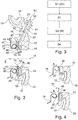
- Figure 1 shows in longitudinal section a detail from a laundry treatment machine 1 in the area of its loading opening 2, which is formed in the front side 3 of its housing 4.
- the loading opening 2 can be closed by a door 6 with a porthole 7 in a manner known per se.
- Figure 1 shows the closed door position.
- An in Figure 1 The tub 10, which is only hinted at, is mounted in a swinging manner in the housing 4 in a manner not shown and has a through opening 12 in its front face 11.
- a laundry drum 13 is arranged, which is rotatably mounted about a longitudinal axis 14 and can be set in rotation by a drive, not shown.
- the laundry drum 13 which is also only partially shown has an end face or laundry drum front face 15 with a loading opening 16 which is aligned in the direction of the longitudinal axis 14 with the through opening 12 and the loading opening 2.
- the loading opening 16 of the laundry drum 13 is radially delimited by an opening edge 18 in the laundry drum front side 15, the opening edge 18 being stiffened by a fold or a flanging.
- the front area or the end face 20 of the edge 18 protrudes into the through opening 12 of the tub 10.
- a feed channel 24 between the feed opening 2 and the through opening 12 forming sleeve 25, the central region 26 of which is designed like a bellows and has an approximately S-shaped longitudinal section.
- the arc 28 of the S-shape close to the longitudinal axis 14 has its inner surface 29 facing the edge 18.
- An end region 30 of the cuff 25 close to the housing is in a manner known per se (cf. DE 10 2015 216 363 A1 ) connected to the edge 32 of the charging opening 2 of the housing 4 in a liquid-tight manner.
- the end region 34 of the cuff 25 close to the caustic container is positively and fluid-tightly connected to the edge region 35 which surrounds the through opening 12.
- a side or surface of the cuff 25 facing the opening edge 18 forms a functional surface 36, which will be explained in more detail below. Between the functional surface 36 and the surface 20 of the edge 18 facing it, a tolerance-related gap 40 required for dynamic reasons is formed.
- Figure 2 shows details in the area of the gap 40 formed between the functional surface 36 and the facing surface 20.
- the same or functionally identical elements are provided with the same reference symbols as in FIG Figure 1 .
- a cuff area 42 having the functional surface 36 is formed on the end area of the cuff 25 near the tub.
- this cuff region 42 can also - as can also be seen in part from the prior art described at the beginning - be formed on another longitudinal section of the cuff 25.
- the cuff area 42 has at least one cavity 45 in this Embodiment is designed as an annular, radially circumferential inner cavity.
- the cavity 45 thus extends in the circumferential direction concentrically around the longitudinal axis 14.
- the cavity 45 can also be formed from a plurality of partial cavities, for example extending in the circumferential direction.
- several at least partially circumferential cavities could be provided axially spaced apart.
- the cavity 45 is delimited by an outer wall 46 as seen in the axial direction. Owing to its wall thickness and / or the material used for it, the outer wall 46 is designed in such a way that the cavity 45 is at least partially flexible. In other words: the cavity 45 can expand in particular in the axial direction (arrow direction B) when a material or a medium is introduced into the cavity 45.
- a hardenable material 50 in particular in the form of hardenable components, can be supplied from the outside through a supply channel or access 51.
- the access 51 has an outside filler neck 52 on the outer circumference 53 of the end region 34 and opens into the cavity or cavities 45.
- An axial partition 55 is preferably provided in the access 51, through which partial channels 56 and 57 are formed. This facilitates the filling process in that hardenable material 50 is fed through the first partial channel 56 and the air displaced from the cavity 45 can easily escape through the second partial channel 57.
- a thermally, chemically and / or optically hardenable material such as a UV-hardening epoxy resin adhesive, can be used as the hardenable material, the sleeve area 42 being designed to be UV-light-permeable at least in the area of the cavity 45.
- one or more spacers 60 are introduced into the space 62 between the functional surface 36 and the facing surface 20 in order to define a desired distance or gap 40 between these surfaces and thus a target position of the functional surface precisely adjust.
- the spacer 60 can consist of a multi-part template which is removed again after the material 50 has hardened.
- a sleeve blank (25 ') which is designed essentially like the sleeve described above, is mounted in the manner described, that is, at least connected to the tub 10 or the edge region of the through opening 12 formed therein.
- the cuff area 42 ( Figure 2 ), in which the previously explained hollow space 45 is or are provided, for example aligned and spaced apart in relation to the surface 20 using a spacer 60.
- a curable material is introduced into the cavity 45 or into the cavities in such a way that the functional surface 36 assumes a predetermined target position 64 in relation to the facing surface 20 of the laundry drum 13.
- the target position can be as in Figure 2 the direct contact with the front-facing contact surface 65 of the spacer 60 can be shown.
- a method step S3 so much hardenable material 50 is introduced into the cavity 45 that the functional surface 36 comes into the desired contact and shape with respect to the spacer 60. Then the curable material is cured as described above by suitable treatment and after curing has taken place and the permanent positioning of the functional surface 36 in relation to the facing surface 20 or the laundry drum 13 of the spacers 60 is removed again (method step S4).
- spacer is dispensed with in the illustrated variant of the method according to the invention in that the functional surface 36 is first brought into direct contact with the corresponding facing surface 20 (upper part of FIG Figure 4 ).
- the laundry drum 13 can be mounted displaceably or adjustably in the axial direction (within small limits) in the direction of arrow A.
- the curable material is then introduced into the cavity or cavities 45 and cured as described.
- the laundry drum 13 is axially displaced back in a defined manner in the direction of arrow B and fixed in the final desired axial position, so that the desired distance or the desired gap dimension 70 of the gap 40 is set by the now permanently fixed functional surface 36 (lower part of the Figure 4 ).
Landscapes
- Engineering & Computer Science (AREA)
- Textile Engineering (AREA)
- Main Body Construction Of Washing Machines And Laundry Dryers (AREA)
- Detail Structures Of Washing Machines And Dryers (AREA)
- External Artificial Organs (AREA)
Abstract
Description
- Die Erfindung betrifft eine Manschette nach dem Oberbegriff des Patentanspruchs 1, ein Wäschebehandlungsgerät nach dem Oberbegriff des Patentanspruchs 7 und ein Verfahren zum Einstellen eines Spaltmaßes zwischen einer Funktionsfläche einer Manschette eines Wäschebehandlungsgeräts und einer dieser Funktionsfläche zugewandten Fläche einer Wäschetrommel.
- Die Erfindung ist insbesondere auf ein Wäschebehandlungsgerät bezogen, bei dem die Wäsche frontseitig durch einen im Wesentlichen axialen Beschickungskanal durch eine in dem Gehäuse des Wäschebehandlungsgerätes ausgebildete, verschließbare Beschickungsöffnung zugeführt wird. Derartige Wäschebehandlungsgeräte werden auch als Frontlader bezeichnet.
- Im Rahmen der vorliegenden Erfindung ist unter dem Begriff Wäschebehandlungsgerät sowohl eine klassische Waschmaschine als auch ein sog. Waschtrockner zu verstehen, der die Funktionen einer Waschmaschine und eines Wäschetrockners vereint.
- Eine Manschette für ein Wäschebehandlungsgerät und ein Wäschebehandlungsgerät der eingangs genannten Art gehen aus der Deutschen Offenlegungsschrift
DE 10 2015 216 363 A1 hervor, die eine frontbeschickbare Waschmaschine mit einem Waschmaschinengehäuse, einem in dem Gehäuse aufgenommenen und gegenüber diesem schwingend beweglich gelagerten Laugenbehälter und einer darin drehbeweglich angeordneten Wäschetrommel beschreibt. Die Wäschetrommel hat eine Frontseite, in der eine zu ihrer Drehachse ausgerichtete Beschickungsöffnung vorgesehen ist. Diese Beschickungsöffnung ist ihrerseits von einer konzentrischen Durchgangsöffnung in der Stirnseite des Laugenbehälters umgeben, die zu einer gehäuseseitigen Beschickungsöffnung ausgerichtet ist. Die gehäuseseitige Beschickungsöffnung und die Durchgangsöffnung des Laugenbehälters sind durch eine schlauchartige Manschette verbunden, die Schwingungsbewegungen des Laugenbehälters relativ zu dem Gehäuse zulässt. Die Manschette bildet einen flüssigkeitsdichten Beschickungskanal, durch den Wäsche in die Wäschetrommel eingebracht bzw. aus dieser entnommen werden kann. - Die Manschette weist ein laugenbehälterseitiges Manschettenende auf, das um die Durchgangsöffnung des Laugenbehälters herum flüssigkeitsdicht und fest mit dem Laugenbehälter verbunden ist. Ein Abschnitt oder Bereich der Manschette weist eine als Funktionsfläche fungierende umlaufende Seite auf. Die Funktionsfläche ist in Einbaulage unter Bildung eines Spaltes zu einer ihr zugewandten Fläche der Wäschetrommelfrontseite positioniert. Diese Fläche kann von dem Rand gebildet sein, der die Beschickungsöffnung in der Wäschetrommelfrontseite begrenzt. Dieser Rand kann als Falz oder Umbördelung ausgestaltet sein.
- Aus der Deutschen Patentschrift
DE 103 58 941 B3 geht ein ähnlich aufgebautes Wäschebehandlungsgerät in Form einer frontbeschickbaren Waschmaschine mit einem Gehäuse, einem schwingend darin gelagerten Laugenbehälter und einer in dem Laugenbehälter angeordneten, drehbar gelagerten zylindrischen Wäschetrommel hervor. Eine Beschickungsöffnung in der Wäschetrommelstirnseite, eine Durchgangsöffnung des Laugenbehälters sowie eine Beschickungsöffnung in der Gehäusefront sind im Wesentlichen in Richtung der Wäschetrommellängsachse fluchtend ausgerichtet. Die Durchgangsöffnung und die Beschickungsöffnung in der Gehäusefront sind durch einen elastomeren Faltenbalg (Manschette) flüssigkeitsdicht miteinander verbunden. Der Faltenbalg weist eine etwa in seinem mittleren Längenbereich ausgebildete, im Längsschnitt etwa S-förmig ausgebildete Falte auf, deren längsachsennaher S-Bogen außenseitig eine umlaufende Funktionsfläche bildet. Die Funktionsfläche ist zu einem die Beschickungsöffnung umgebenden Rand der Wäschetrommelstirnseite beabstandet, wobei in den zwischen der Falte und dem Rand bestehenden Zwischenraum radial ein wenigstens teilweise elastomerer Fortsatz ragt. Der Fortsatz dient dazu, ein Hineinrutschen von Wäsche in den Zwischenraum zu vermeiden. Um ein gewünschtes Spaltmaß zwischen Fortsatz und Rand während der Montage vereinfacht einzustellen, ist der Fortsatz ein von dem Faltenbalg getrenntes Bauteil und das elastomere Material des Fortsatzes besitzt eine größerer Härte als das elastomere Material des Faltenbalgs. - Die Deutsche Patentschrift
DE 102 37 017 B3 beschreibt eine Wäschebehandlungsmaschine mit einer wäscheaufnehmenden, antreibbaren und in einem Laugenbehälter drehbar angeordneten Wäschetrommel. Auch hier ist eine Beschickungsöffnung in der Wäschetrommelfrontseite von einer Durchgangsöffnung des Laugenbehälters umgeben, die über eine elastische Manschette flüssigkeitsdicht mit einer gehäusefrontseitigen Beschickungsöffnung der Wäschebehandlungsmaschine verbunden ist. Im laugenbehälternahen Endbereich weist die Manschette einen Funktionsbereich mit einer im Längsschnitt annähernd U-förmigen Funktionsfläche auf, die dem Rand der Wäschetrommel gegenüberliegend angeordnet ist, der die Beschickungsöffnung begrenzt. Um auch bei großer Füllmenge Wäschebeschädigungen zu vermeiden, ist ein besonders ausgebildeter Wäscheabweiser im Bereich des oberen Totpunktes der Wäschetrommel vorgesehen. - Die Internationale Patentanmeldung mit der Publikationsnummer
WO2009/004045 A1 beschreibt eine Wäschebehandlungsmaschine mit einem Laugenbehälter, bei der ein Ende einer faltenbalgartigen Manschette eine Durchgangsöffnung des Laugenbehälters umgibt und mit dem Laugenbehälter durch Überspritzen oder Umspritzen mit einem Spritzgussmaterial flüssigkeitsdicht verbunden ist. - Vor diesem Hintergrund besteht eine Aufgabe der vorliegenden Erfindung darin, bei Wäschebehandlungsgeräten der eingangs genannten Art, insbesondere bei sogenannten Frontladern, während des Fertigungsprozesses einen aus dynamischen Gründen und aufgrund bauteilgegebener Toleranzen erforderlichen Mindestspalt zwischen der Funktionsfläche und einer korrespondierenden, zugewandten Fläche der Wäschetrommelfrontseite einfach, zuverlässig und reproduzierbar einstellen zu können. Dabei ist das erforderliche Spaltmaß insbesondere von der Laugenbehältergeometrie sowie der Länge der Trommel abhängig.
- Diese Aufgabe wird hinsichtlich einer Manschette für ein Wäschebehandlungsgerät durch eine Manschette mit den Merkmalen des Patentanspruchs 1, hinsichtlich eines Wäschebehandlungsgerätes durch ein Wäschebehandlungsgerät mit den Merkmalen des Patentanspruchs 7 und hinsichtlich eines Verfahren zum Einstellen eines Spaltmaßes zwischen einer Funktionsfläche einer Manschette eines Wäschebehandlungsgeräts und einer dieser Funktionsfläche zugewandten Fläche einer Wäschetrommelfrontseite durch ein Verfahren mit den Merkmalen des Patentanspruchs 8 gelöst.
- Demgemäß ist bei einer Manschette der eingangs genannten Art erfindungsgemäß vorgesehen, dass der Manschettenbereich zumindest einen inneren Hohlraum aufweist, der sich in Umfangsrichtung erstreckt und zumindest teilweise flexibel ausgestaltet ist, und dass mindestens ein Zugang in den Hohlraum mündet.
- Unter einem flexibel gestalteten Hohlraum ist im Rahmen der vorliegenden Erfindung ein Hohlraum zu verstehen, dessen Größe (Volumen) und/oder Geometrie veränderbar ist, also die technische Eigenschaft besitzt, sich leicht mechanisch verändern zu lassen. Dies kann beispielsweise dadurch erfolgen, dass in den Hohlraum ein Füllmaterial eingebracht wird. Je nach beispielsweise Menge, Einbringdruck und Materialeigenschaften des Füllmaterials kann damit der Hohlraum bzw. dessen Geometrie beeinflusst oder aber auch dauerhaft festgelegt werden.
- Hinsichtlich eines aufgabengemäß optimierten Wäschebehandlungsgerätes ist erfindungsgemäß vorgesehen, dass eine erfindungsgemäße Manschette umfasst ist.
- Hinsichtlich eines Verfahrens zum Einstellen eines Spaltmaßes zwischen einer Funktionsfläche einer Manschette eines Wäschebehandlungsgeräts und einer der Funktionsfläche zugewandten Fläche einer Wäschetrommelfrontseite ist erfindungsgemäß vorgesehen, dass ein Manschettenrohling mit einem Manschettenbereich verwendet wird, in dem zumindest ein innerer, sich in Umfangsrichtung erstreckender und zumindest teilweise flexibler Hohlraum vorgesehen ist, der Manschettenrohling mit einem laugenbehälterseitigen Manschettenende mit dem Laugenbehälter verbunden wird, in den Hohlraum ein aushärtbares Material derart eingebracht wird, dass die Funktionsfläche in Bezug auf die zugewandte Fläche der Wäschetrommelfrontseite eine vorgegebene Sollposition einnimmt, und anschließend das aushärtbare Material ausgehärtet wird.
- Ein wesentlicher Aspekt der vorliegenden Erfindung ist es, in einer Manschette, die zur Ausbildung eines flüssigkeitsdichten Beschickungskanals zwischen einer Beschickungsöffnung in einem Gehäuse eines Wäschebehandlungsgeräts und mit einer korrespondierenden Öffnung in der Frontseite eines Laugenbehälters dient, zumindest abschnittsweise, bevorzugt umlaufend, in Umfangsrichtung versetzt und/oder radial verteilt einen oder mehrere Hohlräume vorzusehen. Diese Hohlräume werden im Fertigungsprozess des Wäschebehandlungsgerätes erfindungsgemäß mit einem aushärtbaren Material oder einer aushärtbaren Masse befüllt und können dadurch in ihrem das Spaltmaß bestimmenden Endvolumen oder Geometrie variiert werden. Je nach Füllgrad ist die (insbesondere axiale) Position der Funktionsfläche bzw. deren Geometrie veränderbar. So lässt sich einfach - nämlich z.B. durch Dosierung des eingebrachten Füllmaterials - der sich zu der korrespondierenden Fläche (zweite Funktionsfläche) der Wäschetrommel, nämlich beispielsweise dem Rand um die Beschickungsöffnung in der Wäschetrommel, einstellende Abstand oder Spalt zuverlässig, genau und reproduzierbar definieren. Anschließend wird das Material ausgehärtet oder verfestigt sich, so dass die gewünschte Position bzw. Geometrie der Funktionsfläche dauerhaft eingestellt bleibt. Eine Aushärtung kann - je nach verwendetem Material - in an sich bekannter Weise auf verschiedenste Arten erfolgen. Zum Beispiel kann die Aushärtung bei Mehrkomponentenklebern oder Harzen durch entsprechende Vernetzungs- und chemische Aushärtvorgänge erfolgen. Es können auch thermisch aushärtbare Materialien und/oder durch Licht (beispielsweise UV-aushärtbare) Kleber oder Materialien verwendet werden, wobei nach Einbringung des Materials ein entsprechender für Licht/UV-Strahlung durchlässig gestalteter Bereich der Manschette bestrahlt wird. Ebenso ist eine mechanische Aushärtung oder Verfestigung des Materials oder eine Voraktivierung des Klebers denkbar. Bevorzugt wird ein UV-aushärtbarer Kleber auf Epoxid-Basis verwendet.
- Um das aushärtbare Material dem Hohlraum bzw. den jeweiligen Hohlräumen zuzuführen, ist ein Zugang vorgesehen, der von außen mit einem geeigneten Material beschickbar ist und der in den Hohlraum mündet.
- Vorteilhafte Ausgestaltungen der Erfindung ergeben sich aus der nachfolgenden Beschreibung, den Unteransprüchen und der Figurenbeschreibung, wobei einzelne Merkmale in Kombination oder einzeln angewendet werden können.
- Bei einer bevorzugten Ausgestaltung der erfindungsgemäßen Manschette ist vorgesehen, dass der Zugang radial vom äußeren Umfang des laugenbehälternahen Endbereichs der Manschette in den Hohlraum führt.
- Die Zufuhr von Material in den Hohlraum ist nach einer vorteilhaften Fortbildung der erfindungsgemäßen Manschette dadurch vereinfacht, dass der Zugang zwei Teilkanäle umfasst, wobei ein Teilkanal zur Materialzufuhr und der andere Teilkanal zur Entlüftung des Hohlraums dient.
- Eine besonders präzise und gut steuerbare Einstellung der Position der Funktionsfläche ist nach einer bevorzugten Fortbildung der erfindungsgemäßen Manschette dadurch möglich, dass die Funktionsfläche eine Außenfläche einer flexiblen Außenwand des Hohlraums ist. Die Flexibilität der Außenwand kann dabei insbesondere durch entsprechende Struktur, Dimensionierung (Wanddicke) und/oder durch das für die Manschette in diesem Bereich verwendete (elastische) Material realisiert sein.
- Bei dem erfindungsgemäßen Verfahren zum Einstellen des Spaltmaßes kann die Sollposition bevorzugt durch mindestens einen Abstandshalter zwischen der Funktionsfläche und der dieser zugewandten Fläche der Wäschetrommel definiert werden. Der Abstandshalter kann in Form einer Lehre oder Schablone ausgebildet sein.
- Eine bevorzugte Ausgestaltung des erfindungsgemäßen Verfahrens sieht vor, dass die Sollposition durch Positionierung der Wäschetrommel definiert wird und dass die Wäschetrommel nach Aushärten des Materials axial um das gewünschte Spaltmaß von der Funktionsfläche entfernt wird. Hierdurch kann auf eine Schablone oder einen Abstandshalter verzichtet werden. Durch das Verschieben der Wäschetrommel in axialer Richtung kann das gewünschte Spaltmaß exakt eingestellt werden, wobei ein gewisser Restspalt aus dynamischen Gründen wünschenswert bleibt.
- Die Erfindung wird nachfolgend anhand zeichnerisch dargestellter Ausführungsbeispiele weiter erläutert; es zeigen:
-
Figur 1 einen Längsschnitt eines erfindungsgemäßen Wäschebehandlungsgerätes in Teilansicht, die auf den für die Erfindung wesentlichen Bereich beschränkt ist, -
Figur 2 ausschnittsweise Details ausFigur 1 , -
Figur 3 schematisch den Ablauf des erfindungsgemäßen Verfahrens und -
Figur 4 schematisch zu den korrespondierenden Verfahrensschritten eine Positionierung einer Wäschetrommel. -
Figur 1 zeigt im Längsschnitt einen Ausschnitt aus einer Wäschebehandlungsmaschine 1 im Bereich ihrer Beschickungsöffnung 2, die in der Frontseite 3 ihres Gehäuses 4 ausgebildet ist. Die Beschickungsöffnung 2 ist in an sich bekannter Weise von einer Tür 6 mit einem Bullauge 7 verschließbar.Figur 1 zeigt die geschlossene Türposition. Ein inFigur 1 nur andeutungsweise gezeigter Laugenbehälter 10 ist in nicht näher gezeigter Weise schwingend in dem Gehäuse 4 gelagert und weist in seiner frontseitigen Stirnseite 11 eine Durchgangsöffnung 12 auf. In dem Laugenbehälter 10 ist eine Wäschetrommel 13 angeordnet, die um eine Längsachse 14 drehbar gelagert und von einem nicht gezeigten Antrieb in Rotation versetzbar ist. Die ebenfalls nur teilweise gezeigte Wäschetrommel 13 hat eine Stirnseite oder Wäschetrommelfrontseite 15 mit einer Beschickungsöffnung 16, die in Richtung der Längsachse 14 mit der Durchgangsöffnung 12 und der Beschickungsöffnung 2 fluchtet. Die Beschickungsöffnung 16 der Wäschetrommel 13 ist durch einen Öffnungsrand 18 in der Wäschetrommelfrontseite 15 radial begrenzt, wobei der Öffnungsrand 18 durch einen Falz oder eine Umbördelung versteift ist. Der frontseitige Bereich bzw. die stirnseitige Fläche 20 des Rands 18 ragt in diesem Ausführungsbeispiel in die Durchgangsöffnung 12 des Laugenbehälters 10 hinein. - Zwischen dem Laugenbehälter 10 und dem Gehäuse 4 erstreckt sich eine einen Beschickungskanal 24 zwischen der Beschickungsöffnung 2 und der Durchgangsöffnung 12 ausbildende Manschette 25, deren mittlerer Bereich 26 faltenbalgartig gestaltet ist und einen etwa S-förmigen Längsschnitt aufweist. Der der Längsachse 14 nahe Bogen 28 der S-Form ist mit seiner Innenfläche 29 dem Rand 18 zugewandt. Ein gehäusenaher Endbereich 30 der Manschette 25 ist in an sich bekannter Weise (vergleiche
DE 10 2015 216 363 A1 ) mit dem Rand 32 der Beschickungsöffnung 2 des Gehäuses 4 flüssigkeitsdicht verbunden. Der laugenbehälternahe Endbereich 34 der Manschette 25 ist formschlüssig flüssigkeitsdicht mit dem Randbereich 35 verbunden, der die Durchgangsöffnung 12 umgibt. Eine dem Öffnungsrand 18 zugewandte Seite oder Fläche der Manschette 25 bildet eine nachfolgend noch näher erläuterte Funktionsfläche 36. Zwischen der Funktionsfläche 36 und der ihr zugewandten Fläche 20 des Randes 18 ist ein toleranzbedingter und aus dynamischen Gründen erforderlicher Spalt 40 gebildet. -
Figur 2 zeigt Details im Bereich des zwischen der Funktionsfläche 36 und der zugewandten Fläche 20 gebildeten Spaltes 40. Dabei sind gleiche oder funktionsgleiche Elemente mit denselben Bezugszeichen versehen wie inFigur 1 . Allerdings sind verschiedene inFigur 1 gezeigte Teile und Schattenkanten rotationssymmetrischer Teile wie beispielsweise der Wäschetrommel aus Darstellungsgründen fortgelassen. - Ein die Funktionsfläche 36 aufweisender Manschettenbereich 42 ist in diesem Ausführungsbeispiel am laugenbehälternahen Endbereich der Manschette 25 ausgebildet. Grundsätzlich kann dieser Manschettenbereich 42 aber auch - wie teilweise auch aus dem eingangs beschriebenen Stand der Technik hervorgeht - an einem anderen Längsabschnitt der Manschette 25 ausgebildet sein.
- Der Manschettenbereich 42 weist wenigstens einen Hohlraum 45 auf, der in diesem Ausführungsbeispiel als ringförmiger, radial umlaufender innerer Hohlraum ausgestaltet ist. Der Hohlraum 45 erstreckt sich also in Umfangsrichtung konzentrisch um die Längsachse 14. Grundsätzlich kann der Hohlraum 45 aber auch aus mehreren, z.B. sich in Umfangsrichtung erstreckenden Teilhohlräumen gebildet sein. Ebenso könnten mehrere zumindest teilweise umlaufende Hohlräume axial beabstandet vorgesehen sein. Der Hohlraum 45 ist in axialer Richtung gesehen durch eine Außenwand 46 begrenzt. Die Außenwand 46 ist durch ihre Wanddicke und/oder das für sie verwendete Material so ausgebildet, dass sich der Hohlraum 45 zumindest teilweise flexibel verhält. Mit anderen Worten: Der Hohlraum 45 kann insbesondere in axialer Richtung (Pfeilrichtung B) expandieren, wenn in den Hohlraum 45 ein Material oder ein Medium eingebracht wird.
- Wie in
Figur 2 angedeutet, kann ein aushärtbares Material 50, insbesondere in Form aushärtbarer Komponenten, durch einen Zuführkanal oder Zugang 51 von außen zugeführt werden. Der Zugang 51 weist einen außenseitigen Einfüllstutzen 52 am äußeren Umfang 53 des Endbereichs 34 auf und mündet in den bzw. die Hohlräume 45. Selbstverständlich könnten auch mehrere Zuführstutzen bzw. Zugänge vorgesehen sein. Bevorzugt ist eine axiale Trennwand 55 in dem Zugang 51 vorgesehen, durch die Teilkanäle 56 und 57 gebildet sind. Dies erleichtert den Einfüllvorgang, indem durch den ersten Teilkanal 56 aushärtbares Material 50 zugeführt wird und die dadurch aus dem Hohlraum 45 verdrängte Luft durch den zweiten Teilkanal 57 leicht entweichen kann. - Als aushärtbares Material kann besonders bevorzugt ein thermisch, chemisch und/oder optisch aushärtbares Material, wie beispielsweise ein UV-aushärtender Epoxidharz-Kleber verwendet werden, wobei der Manschettenbereich 42 zumindest im Bereich des Hohlraums 45 UV-Licht durchlässig ausgeführt ist.
- Vor Zufuhr von aushärtbarem Material wird bzw. werden ein oder mehrere Abstandshalter 60 in den Zwischenraum 62 zwischen der Funktionsfläche 36 und der zugewandten Fläche 20 eingebracht, um ein gewünschtes Abstandsmaß bzw. einen Spalt 40 zwischen diesen Flächen zu definieren und um so eine Sollposition der Funktionsfläche präzise einzustellen. Der Abstandshalter 60 kann aus einer mehrteiligen Schablone bestehen, die nach erfolgter Aushärtung des Materials 50 wieder entnommen wird.
- Mit zusätzlicher Bezugnahme auf
Figur 3 werden zusammenfassend die wesentlichen Verfahrensschritte zum Einstellen eines gewünschten Spaltmaßes 70 des Spalts 40 (Figur 2 ) erläutert. In einem ersten Verfahrensschritt S1 wird ein Manschettenrohling (25'), der im Wesentlichen wie die zuvor beschriebene Manschette ausgebildet ist, in beschriebener Weise montiert, also zumindest mit dem Laugenbehälter 10 bzw. dem Randbereich der in diesem gebildeten Durchgangsöffnung 12 verbunden. - Im anschließenden Verfahrensschritt S2 wird der Manschettenbereich 42 (
Figur 2 ), in dem der bzw. die zuvor erläuterten Hohlräume 45 vorgesehen ist bzw. sind, beispielsweise unter Verwendung eines Abstandshalters 60 in Relation zu der Fläche 20 ausgerichtet und beabstandet. Anschließend wird wie beschrieben in den Hohlraum 45 bzw. in die Hohlräume ein aushärtbares Material derart eingebracht, dass die Funktionsfläche 36 in Bezug auf die zugewandte Fläche 20 der Wäschetrommel 13 eine vorgegebene Sollposition 64 einnimmt. Die Sollposition kann wie inFigur 2 gezeigt die direkte Anlage an der frontseitig orientierten Anlagefläche 65 des Abstandshalters 60 sein. - Anschließend wird in einem Verfahrensschritt S3 so viel aushärtbares Material 50 in den Hohlraum 45 eingebracht, dass die Funktionsfläche 36 in gewünschte Anlage und Form in Bezug auf den Abstandshalter 60 kommt. Dann wird das aushärtbare Material wie zuvor beschrieben durch geeignete Behandlung ausgehärtet und nach erfolgter Aushärtung und der damit bewirkten dauerhaften Positionierung der Funktionsfläche 36 in Bezug auf die zugewandte Fläche 20 bzw. die Wäschetrommel 13 der Abstandshalter 60 wieder entfernt (Verfahrensschritt S4).
- Bei einer mithilfe der
Figur 4 illustrierten Variante des erfindungsgemäßen Verfahrens wird auf einen Abstandshalter verzichtet, indem zunächst die Funktionsfläche 36 in direkte Anlage zu der korrespondierenden zugewandten Fläche 20 gebracht wird (oberer Teil derFigur 4 ). Dazu kann beispielsweise die Wäschetrommel 13 in Pfeilrichtung A in axialer Richtung (in geringen Grenzen) verschiebbar bzw. einstellbar gelagert sein. Anschließend wird das aushärtbare Material wie beschrieben in den oder die Hohlräume 45 eingebracht und ausgehärtet. Nach Aushärtung wird die Wäschetrommel 13 in Pfeilrichtung B axial definiert zurück verschoben und in der final gewünschten Axialposition fixiert, so dass sich durch die nunmehr dauerhaft fixierte Funktionsfläche 36 deren gewünschter Abstand bzw. das gewünschte Spaltmaß 70 des Spalts 40 einstellt (unterer Teil derFigur 4 ). -
- 1
- Wäschebehandlungsmaschine
- 2
- Beschickungsöffnung
- 3
- Frontseite
- 4
- Gehäuse
- 6
- Tür
- 7
- Bullauge
- 10
- Laugenbehälter
- 11
- Stirnseite
- 12
- Durchgangsöffnung
- 13
- Wäschetrommel
- 14
- Längsachse
- 15
- Wäschetrommelfrontseite
- 16
- Beschickungsöffnung
- 18
- Öffnungsrand
- 20
- frontseitige Fläche
- 24
- Beschickungskanal
- 25
- Manschette
- 25'
- Manschettenrohling
- 26
- mittlerer Bereich der Manschette
- 28
- innerer Bogen
- 29
- Innenfläche
- 30
- gehäusenaher Endbereich
- 32
- Rand
- 34
- laugenbehälternaher Endbereich
- 35
- Randbereich
- 36
- Funktionsfläche
- 40
- Spalt
- 42
- Manschettenbereich
- 45
- Hohlraum
- 46
- Außenwand
- 50
- aushärtbares Material
- 51
- Zugang
- 52
- Einfüllstutzen
- 53
- Umfang
- 55
- Trennwand
- 56, 57
- Teilkanäle
- 60
- Abstandshalter
- 62
- Zwischenraum
- 64
- Sollposition
- 64'
- Sollposition
- 65
- Anlagefläche
- 70
- Spaltmaß
- A
- Pfeilrichtung
- B
- Pfeilrichtung
- S1
- Verfahrensschritt
- S2
- Verfahrensschritt
- S3
- Verfahrensschritt
- S4
- Verfahrensschritt
Claims (10)
- Manschette (25) für ein Wäschebehandlungsgerät (1), das ein Gehäuse (4) und einen darin enthaltenen Laugenbehälter (10) mit einer darin drehbar angeordneten Wäschetrommel (13) aufweist,- mit einem Manschettenbereich (42) mit einer Funktionsfläche (36), die in Einbaulage unter Bildung eines Spaltes (40) zu einer ihr zugewandten Fläche (20) der Wäschetrommelfrontseite (15) positioniert ist,- wobei die Manschette (25) einen Beschickungskanal (24) zwischen einer gehäuseseitigen Beschickungsöffnung (2) und einer laugenbehälterseitigen Durchgangsöffnung (12) bildet,
dadurch gekennzeichnet,- dass der Manschettenbereich (42) zumindest einen inneren Hohlraum (45) aufweist, der sich in Umfangsrichtung erstreckt und zumindest teilweise flexibel ausgestaltet ist, und- dass mindestens ein Zugang (51) in den Hohlraum (45) mündet. - Manschette nach Anspruch 1,
dadurch gekennzeichnet, dass
der Zugang (51) radial vom äußeren Umfang (53) eines laugenbehälternahen Endbereichs (34) der Manschette (25) in den Hohlraum (45) führt. - Manschette nach Anspruch 1 oder 2,
dadurch gekennzeichnet, dass
der Zugang (51) zwei Teilkanäle (56, 57) umfasst, von denen ein Teilkanal (56) zur Zufuhr von Material (50) in den Hohlraum (45) und der andere Teilkanal (57) zur Entlüftung des Hohlraums (45) dient. - Manschette nach einem der vorhergehenden Ansprüche,
dadurch gekennzeichnet, dass
die Funktionsfläche (36) eine Außenfläche einer flexiblen Außenwand (46) des Hohlraums (45) ist. - Manschette nach einem der vorhergehenden Ansprüche,
dadurch gekennzeichnet, dass
in den Hohlraum (45) ein aushärtbares Material (50), insbesondere ein Epoxid basierter Kleber, eingebracht ist. - Manschette nach einem der vorhergehenden Ansprüche,
dadurch gekennzeichnet, dass
in den Hohlraum (45) ein UV-aushärtbarer Epoxid basierter Kleber eingebracht ist und der Manschettenbereich (42) zumindest im Bereich des Hohlraums UV-Licht durchlässig ausgebildet ist. - Wäschebehandlungsgerät (1) mit- einem Gehäuse (4), einem Laugenbehälter (10), in dem eine Wäschetrommel (13) drehbar angeordnet ist, und einer Manschette (25), die einen Beschickungskanal (24) bildet, der von einer Beschickungsöffnung (2) in der Frontseite des Gehäuses (4) zu einer frontseitigen Durchgangsöffnung (12) des Laugenbehälters (10) führt, und die einen Manschettenbereich (42) mit einer Funktionsfläche (36) aufweist, die durch einen Spalt (40) zu einer ihr zugewandten Fläche (20) der Wäschetrommelfrontseite (15) beabstandet ist,
dadurch gekennzeichnet dass,- die Manschette (25) nach einem der Ansprüche 1 bis 5 ausgebildet ist. - Verfahren zum Einstellen eines Spaltmaßes (70) zwischen einer Funktionsfläche (36) einer Manschette (25) eines Wäschebehandlungsgeräts (1) und einer der Funktionsfläche (36) zugewandten Fläche (20) einer Wäschetrommelfrontseite (15), bei dem,- ein Manschettenrohling (25') mit einem Manschettenbereich (42) verwendet wird, in dem zumindest ein innerer, sich in Umfangsrichtung erstreckender und zumindest teilweise flexibler Hohlraum (45) vorgesehen ist,- der Manschettenrohling (25') mit einem Endbereich (34) mit dem Laugenbehälter (10) verbunden wird,- in den Hohlraum (45) ein aushärtbares Material (50) derart eingebracht wird, dass die Funktionsfläche (36) in Bezug auf die zugewandte Fläche (20) der Wäschetrommelfrontseite (15) eine vorgegebene Sollposition (64) einnimmt, und- anschließend das aushärtbare Material (50) ausgehärtet wird.
- Verfahren nach Anspruch 8,
dadurch gekennzeichnet, dass
die Sollposition (64) durch mindestens einen zwischen der Funktionsfläche (36) und der dieser zugewandten Fläche (20) der Wäschetrommelfrontseite (15) eingebrachten Abstandshalter (60) definiert wird. - Verfahren nach Anspruch 9,
dadurch gekennzeichnet, dass
die Sollposition (64') durch Positionierung der Wäschetrommel (13) definiert wird und die Wäschetrommel (13) nach Aushärten des Materials (50) axial um das gewünschte Spaltmaß (70) von der Funktionsfläche (36) entfernt wird.
Applications Claiming Priority (1)
| Application Number | Priority Date | Filing Date | Title |
|---|---|---|---|
| DE102019209205.5A DE102019209205A1 (de) | 2019-06-26 | 2019-06-26 | Manschette für ein Wäschebehandlungsgerät, Wäschebehandlungsgerät und Verfahren zum Einstellen eines Spaltmaßes |
Publications (2)
| Publication Number | Publication Date |
|---|---|
| EP3757272A1 true EP3757272A1 (de) | 2020-12-30 |
| EP3757272B1 EP3757272B1 (de) | 2023-08-09 |
Family
ID=71083428
Family Applications (1)
| Application Number | Title | Priority Date | Filing Date |
|---|---|---|---|
| EP20179062.3A Active EP3757272B1 (de) | 2019-06-26 | 2020-06-09 | Manschette für ein wäschebehandlungsgerät, wäschebehandlungsgerät und verfahren zum einstellen eines spaltmasses |
Country Status (3)
| Country | Link |
|---|---|
| EP (1) | EP3757272B1 (de) |
| CN (1) | CN112144233A (de) |
| DE (1) | DE102019209205A1 (de) |
Families Citing this family (1)
| Publication number | Priority date | Publication date | Assignee | Title |
|---|---|---|---|---|
| CN115506111B (zh) * | 2021-06-22 | 2025-03-11 | 无锡小天鹅电器有限公司 | 衣物处理设备 |
Citations (9)
| Publication number | Priority date | Publication date | Assignee | Title |
|---|---|---|---|---|
| GB1426076A (en) * | 1973-01-29 | 1976-02-25 | Hotpoint Ltd | Washing and like machines |
| DE10237017B3 (de) | 2002-08-13 | 2004-01-08 | Whirlpool Corp., Benton Harbor | Wäschebehandlungsmaschine |
| DE10358941B3 (de) | 2003-12-15 | 2005-05-12 | Miele & Cie. Kg | Frontbeschickbare Waschmaschine |
| DE102005055777B3 (de) * | 2005-11-21 | 2006-11-16 | Miele & Cie. Kg | Stirnseitig beschickbare Wäschebehandlungsmaschine, wie Waschmaschine oder Waschtrockner |
| WO2009004045A1 (en) | 2007-07-04 | 2009-01-08 | Arcelik Anonim Sirketi | A washer/dryer |
| EP2080830A1 (de) * | 2008-01-15 | 2009-07-22 | Miele & Cie. KG | Frontbeschickbare Trommelwaschmaschine mit Wäscheabweiser |
| DE102011005889A1 (de) * | 2011-03-22 | 2012-09-27 | BSH Bosch und Siemens Hausgeräte GmbH | Von vorne beschickbare Waschmaschine mit einer Manschette |
| US20170051446A1 (en) * | 2014-02-13 | 2017-02-23 | Samsung Electronics Co., Ltd | Washing machine |
| DE102015216363A1 (de) | 2015-08-27 | 2017-03-02 | BSH Hausgeräte GmbH | Waschmaschine mit Türbereich zur Vermeidung von Wäscheschäden |
Family Cites Families (5)
| Publication number | Priority date | Publication date | Assignee | Title |
|---|---|---|---|---|
| DE102006031352A1 (de) * | 2006-07-06 | 2008-01-10 | BSH Bosch und Siemens Hausgeräte GmbH | Von vorn beschickbare Waschmaschine |
| TR200707121A2 (tr) * | 2007-10-18 | 2009-06-22 | Bsh Ev Aletleri̇ Sanayi̇ Ve Ti̇caret Anoni̇m Şi̇rketi̇ | Conta ve bu contaya sahip tamburlu çamaşır makinesi |
| DE102008018731A1 (de) * | 2008-04-14 | 2009-10-15 | BSH Bosch und Siemens Hausgeräte GmbH | Waschmaschine mit einem Maschinengehäuse |
| DE102011079448A1 (de) * | 2011-07-20 | 2013-01-24 | BSH Bosch und Siemens Hausgeräte GmbH | Von vorne beschickbare Waschmaschine mit einer Manschette |
| CN202247389U (zh) * | 2011-10-19 | 2012-05-30 | 合肥荣事达三洋电器股份有限公司 | 滚筒洗衣机 |
-
2019
- 2019-06-26 DE DE102019209205.5A patent/DE102019209205A1/de not_active Withdrawn
-
2020
- 2020-06-09 EP EP20179062.3A patent/EP3757272B1/de active Active
- 2020-06-19 CN CN202010563887.0A patent/CN112144233A/zh active Pending
Patent Citations (9)
| Publication number | Priority date | Publication date | Assignee | Title |
|---|---|---|---|---|
| GB1426076A (en) * | 1973-01-29 | 1976-02-25 | Hotpoint Ltd | Washing and like machines |
| DE10237017B3 (de) | 2002-08-13 | 2004-01-08 | Whirlpool Corp., Benton Harbor | Wäschebehandlungsmaschine |
| DE10358941B3 (de) | 2003-12-15 | 2005-05-12 | Miele & Cie. Kg | Frontbeschickbare Waschmaschine |
| DE102005055777B3 (de) * | 2005-11-21 | 2006-11-16 | Miele & Cie. Kg | Stirnseitig beschickbare Wäschebehandlungsmaschine, wie Waschmaschine oder Waschtrockner |
| WO2009004045A1 (en) | 2007-07-04 | 2009-01-08 | Arcelik Anonim Sirketi | A washer/dryer |
| EP2080830A1 (de) * | 2008-01-15 | 2009-07-22 | Miele & Cie. KG | Frontbeschickbare Trommelwaschmaschine mit Wäscheabweiser |
| DE102011005889A1 (de) * | 2011-03-22 | 2012-09-27 | BSH Bosch und Siemens Hausgeräte GmbH | Von vorne beschickbare Waschmaschine mit einer Manschette |
| US20170051446A1 (en) * | 2014-02-13 | 2017-02-23 | Samsung Electronics Co., Ltd | Washing machine |
| DE102015216363A1 (de) | 2015-08-27 | 2017-03-02 | BSH Hausgeräte GmbH | Waschmaschine mit Türbereich zur Vermeidung von Wäscheschäden |
Also Published As
| Publication number | Publication date |
|---|---|
| DE102019209205A1 (de) | 2020-12-31 |
| EP3757272B1 (de) | 2023-08-09 |
| CN112144233A (zh) | 2020-12-29 |
Similar Documents
| Publication | Publication Date | Title |
|---|---|---|
| EP2241666B1 (de) | Verfahren zur Herstellung eines Waschaggregats mit einem Laugenbehälter aus Kunststoff | |
| DE3650511T2 (de) | Verfahren zur Herstellung eines Waschmaschinenbehälters und mittels eines solchen Verfahrens hergestellter Behälter | |
| EP3959798B1 (de) | Gehäuse einer elektrischen maschine mit optimiertem dichtungsring | |
| CH645960A5 (de) | Kugelschraubtrieb. | |
| DE19832254C2 (de) | Kugelgelenk und Verfahren zu dessen Herstellung | |
| EP1482604A2 (de) | Schleifringelement und Verfahren zu dessen Herstellung | |
| CH667895A5 (de) | Pumpen-fluegelrad und verfahren zur herstellung desselben mittels ko-spritzgiessen. | |
| EP3757272A1 (de) | Manschette für ein wäschebehandlungsgerät, wäschebehandlungsgerät und verfahren zum einstellen eines spaltmasses | |
| DE10359011B3 (de) | Frontbeschickbare Waschmaschine und Verfahren zur Herstellung einer solchen Waschmaschine | |
| DE10328122A1 (de) | Näherungssensor mit verbesserter Positioniergenauigkeit für Umgebungselemente der Nachweisspule | |
| EP1700943A1 (de) | Waschmaschine mit Einspritzdüse | |
| DE102014206634A1 (de) | Lageranordnung und Waschmaschine mit einer Lageranordnung | |
| DE102018204716A1 (de) | Manschette und Wäschebehandlungsgerät | |
| EP3283681B1 (de) | Anordnung mit einer wäschetrommel und einer unwuchtausgleichsvorrichtung, haushaltsgerät zur pflege von wäschestücken und verfahren zum befestigen einer unwuchtausgleichsvorrichtung | |
| EP0865736A2 (de) | Düse zum Herstellen eines Verzehrgutes | |
| DE29712762U1 (de) | Eingangsfilter für eine Flüssigkeitspumpe, insbesondere für Waschmaschinen | |
| WO2011072712A1 (de) | Kunststoff-bauteil, insbesondere kunststoff-laugenbehälter, und verfahren zur herstellung des kunststoff-bauteils | |
| EP2497853B1 (de) | Kunststofflaugenbehälter für eine Waschmaschine mit einer Schraubverbindung zur Festlegung einer aus Kunststoff gefertigten Laugenbehälterkappe an einem Kunststofflaugenbehältermantel | |
| WO2021078493A1 (de) | Spritzgussdüse für ein spritzgiesswerkzeug, spritzgiesswerkzeug, düsennadel für eine spritzgussdüse sowie verfahren zum einspritzen eines rohmaterials | |
| DE10227036C1 (de) | Waschaggregat für eine Waschmaschine | |
| EP3245325B1 (de) | Haushaltsgerät zur pflege von wäschestücken mit einer spezifischen anbindung eines dämpfers an ein gehäuse des haushaltsgeräts | |
| DE102011080054A1 (de) | Injektionskopf und Auswerfer einer Injektionsvorrichtung | |
| EP3060712B1 (de) | Verfahren zum befestigen einer unwuchtausgleichsvorrichtung an einer wäschetrommel, anordnung für ein haushaltsgerät und haushaltsgerät | |
| DE102011006783A1 (de) | Von vorne beschickbare Wäschepflegemaschine mit einer Manschette | |
| AT500749A1 (de) | Signalgebendes magnetgetriebe-element aus kunststoff, werkzeug zur herstellung und verfahren zum betrieb des werkzeuges |
Legal Events
| Date | Code | Title | Description |
|---|---|---|---|
| PUAI | Public reference made under article 153(3) epc to a published international application that has entered the european phase |
Free format text: ORIGINAL CODE: 0009012 |
|
| STAA | Information on the status of an ep patent application or granted ep patent |
Free format text: STATUS: THE APPLICATION HAS BEEN PUBLISHED |
|
| AK | Designated contracting states |
Kind code of ref document: A1 Designated state(s): AL AT BE BG CH CY CZ DE DK EE ES FI FR GB GR HR HU IE IS IT LI LT LU LV MC MK MT NL NO PL PT RO RS SE SI SK SM TR |
|
| AX | Request for extension of the european patent |
Extension state: BA ME |
|
| STAA | Information on the status of an ep patent application or granted ep patent |
Free format text: STATUS: REQUEST FOR EXAMINATION WAS MADE |
|
| 17P | Request for examination filed |
Effective date: 20210630 |
|
| RBV | Designated contracting states (corrected) |
Designated state(s): AL AT BE BG CH CY CZ DE DK EE ES FI FR GB GR HR HU IE IS IT LI LT LU LV MC MK MT NL NO PL PT RO RS SE SI SK SM TR |
|
| GRAP | Despatch of communication of intention to grant a patent |
Free format text: ORIGINAL CODE: EPIDOSNIGR1 |
|
| STAA | Information on the status of an ep patent application or granted ep patent |
Free format text: STATUS: GRANT OF PATENT IS INTENDED |
|
| INTG | Intention to grant announced |
Effective date: 20230314 |
|
| GRAS | Grant fee paid |
Free format text: ORIGINAL CODE: EPIDOSNIGR3 |
|
| GRAA | (expected) grant |
Free format text: ORIGINAL CODE: 0009210 |
|
| STAA | Information on the status of an ep patent application or granted ep patent |
Free format text: STATUS: THE PATENT HAS BEEN GRANTED |
|
| AK | Designated contracting states |
Kind code of ref document: B1 Designated state(s): AL AT BE BG CH CY CZ DE DK EE ES FI FR GB GR HR HU IE IS IT LI LT LU LV MC MK MT NL NO PL PT RO RS SE SI SK SM TR |
|
| REG | Reference to a national code |
Ref country code: GB Ref legal event code: FG4D Free format text: NOT ENGLISH |
|
| REG | Reference to a national code |
Ref country code: CH Ref legal event code: EP |
|
| REG | Reference to a national code |
Ref country code: DE Ref legal event code: R096 Ref document number: 502020004579 Country of ref document: DE |
|
| REG | Reference to a national code |
Ref country code: IE Ref legal event code: FG4D Free format text: LANGUAGE OF EP DOCUMENT: GERMAN |
|
| REG | Reference to a national code |
Ref country code: LT Ref legal event code: MG9D |
|
| REG | Reference to a national code |
Ref country code: NL Ref legal event code: MP Effective date: 20230809 |
|
| PG25 | Lapsed in a contracting state [announced via postgrant information from national office to epo] |
Ref country code: GR Free format text: LAPSE BECAUSE OF FAILURE TO SUBMIT A TRANSLATION OF THE DESCRIPTION OR TO PAY THE FEE WITHIN THE PRESCRIBED TIME-LIMIT Effective date: 20231110 |
|
| PG25 | Lapsed in a contracting state [announced via postgrant information from national office to epo] |
Ref country code: IS Free format text: LAPSE BECAUSE OF FAILURE TO SUBMIT A TRANSLATION OF THE DESCRIPTION OR TO PAY THE FEE WITHIN THE PRESCRIBED TIME-LIMIT Effective date: 20231209 |
|
| PG25 | Lapsed in a contracting state [announced via postgrant information from national office to epo] |
Ref country code: SE Free format text: LAPSE BECAUSE OF FAILURE TO SUBMIT A TRANSLATION OF THE DESCRIPTION OR TO PAY THE FEE WITHIN THE PRESCRIBED TIME-LIMIT Effective date: 20230809 Ref country code: RS Free format text: LAPSE BECAUSE OF FAILURE TO SUBMIT A TRANSLATION OF THE DESCRIPTION OR TO PAY THE FEE WITHIN THE PRESCRIBED TIME-LIMIT Effective date: 20230809 Ref country code: PT Free format text: LAPSE BECAUSE OF FAILURE TO SUBMIT A TRANSLATION OF THE DESCRIPTION OR TO PAY THE FEE WITHIN THE PRESCRIBED TIME-LIMIT Effective date: 20231211 Ref country code: NO Free format text: LAPSE BECAUSE OF FAILURE TO SUBMIT A TRANSLATION OF THE DESCRIPTION OR TO PAY THE FEE WITHIN THE PRESCRIBED TIME-LIMIT Effective date: 20231109 Ref country code: NL Free format text: LAPSE BECAUSE OF FAILURE TO SUBMIT A TRANSLATION OF THE DESCRIPTION OR TO PAY THE FEE WITHIN THE PRESCRIBED TIME-LIMIT Effective date: 20230809 Ref country code: LV Free format text: LAPSE BECAUSE OF FAILURE TO SUBMIT A TRANSLATION OF THE DESCRIPTION OR TO PAY THE FEE WITHIN THE PRESCRIBED TIME-LIMIT Effective date: 20230809 Ref country code: LT Free format text: LAPSE BECAUSE OF FAILURE TO SUBMIT A TRANSLATION OF THE DESCRIPTION OR TO PAY THE FEE WITHIN THE PRESCRIBED TIME-LIMIT Effective date: 20230809 Ref country code: IS Free format text: LAPSE BECAUSE OF FAILURE TO SUBMIT A TRANSLATION OF THE DESCRIPTION OR TO PAY THE FEE WITHIN THE PRESCRIBED TIME-LIMIT Effective date: 20231209 Ref country code: HR Free format text: LAPSE BECAUSE OF FAILURE TO SUBMIT A TRANSLATION OF THE DESCRIPTION OR TO PAY THE FEE WITHIN THE PRESCRIBED TIME-LIMIT Effective date: 20230809 Ref country code: GR Free format text: LAPSE BECAUSE OF FAILURE TO SUBMIT A TRANSLATION OF THE DESCRIPTION OR TO PAY THE FEE WITHIN THE PRESCRIBED TIME-LIMIT Effective date: 20231110 Ref country code: FI Free format text: LAPSE BECAUSE OF FAILURE TO SUBMIT A TRANSLATION OF THE DESCRIPTION OR TO PAY THE FEE WITHIN THE PRESCRIBED TIME-LIMIT Effective date: 20230809 |
|
| PG25 | Lapsed in a contracting state [announced via postgrant information from national office to epo] |
Ref country code: PL Free format text: LAPSE BECAUSE OF FAILURE TO SUBMIT A TRANSLATION OF THE DESCRIPTION OR TO PAY THE FEE WITHIN THE PRESCRIBED TIME-LIMIT Effective date: 20230809 |
|
| PG25 | Lapsed in a contracting state [announced via postgrant information from national office to epo] |
Ref country code: ES Free format text: LAPSE BECAUSE OF FAILURE TO SUBMIT A TRANSLATION OF THE DESCRIPTION OR TO PAY THE FEE WITHIN THE PRESCRIBED TIME-LIMIT Effective date: 20230809 |
|
| PG25 | Lapsed in a contracting state [announced via postgrant information from national office to epo] |
Ref country code: SM Free format text: LAPSE BECAUSE OF FAILURE TO SUBMIT A TRANSLATION OF THE DESCRIPTION OR TO PAY THE FEE WITHIN THE PRESCRIBED TIME-LIMIT Effective date: 20230809 Ref country code: RO Free format text: LAPSE BECAUSE OF FAILURE TO SUBMIT A TRANSLATION OF THE DESCRIPTION OR TO PAY THE FEE WITHIN THE PRESCRIBED TIME-LIMIT Effective date: 20230809 Ref country code: ES Free format text: LAPSE BECAUSE OF FAILURE TO SUBMIT A TRANSLATION OF THE DESCRIPTION OR TO PAY THE FEE WITHIN THE PRESCRIBED TIME-LIMIT Effective date: 20230809 Ref country code: EE Free format text: LAPSE BECAUSE OF FAILURE TO SUBMIT A TRANSLATION OF THE DESCRIPTION OR TO PAY THE FEE WITHIN THE PRESCRIBED TIME-LIMIT Effective date: 20230809 Ref country code: DK Free format text: LAPSE BECAUSE OF FAILURE TO SUBMIT A TRANSLATION OF THE DESCRIPTION OR TO PAY THE FEE WITHIN THE PRESCRIBED TIME-LIMIT Effective date: 20230809 Ref country code: CZ Free format text: LAPSE BECAUSE OF FAILURE TO SUBMIT A TRANSLATION OF THE DESCRIPTION OR TO PAY THE FEE WITHIN THE PRESCRIBED TIME-LIMIT Effective date: 20230809 Ref country code: SK Free format text: LAPSE BECAUSE OF FAILURE TO SUBMIT A TRANSLATION OF THE DESCRIPTION OR TO PAY THE FEE WITHIN THE PRESCRIBED TIME-LIMIT Effective date: 20230809 |
|
| REG | Reference to a national code |
Ref country code: DE Ref legal event code: R097 Ref document number: 502020004579 Country of ref document: DE |
|
| PG25 | Lapsed in a contracting state [announced via postgrant information from national office to epo] |
Ref country code: IT Free format text: LAPSE BECAUSE OF FAILURE TO SUBMIT A TRANSLATION OF THE DESCRIPTION OR TO PAY THE FEE WITHIN THE PRESCRIBED TIME-LIMIT Effective date: 20230809 |
|
| PLBE | No opposition filed within time limit |
Free format text: ORIGINAL CODE: 0009261 |
|
| STAA | Information on the status of an ep patent application or granted ep patent |
Free format text: STATUS: NO OPPOSITION FILED WITHIN TIME LIMIT |
|
| PGFP | Annual fee paid to national office [announced via postgrant information from national office to epo] |
Ref country code: DE Payment date: 20240630 Year of fee payment: 5 |
|
| 26N | No opposition filed |
Effective date: 20240513 |
|
| PG25 | Lapsed in a contracting state [announced via postgrant information from national office to epo] |
Ref country code: SI Free format text: LAPSE BECAUSE OF FAILURE TO SUBMIT A TRANSLATION OF THE DESCRIPTION OR TO PAY THE FEE WITHIN THE PRESCRIBED TIME-LIMIT Effective date: 20230809 |
|
| PG25 | Lapsed in a contracting state [announced via postgrant information from national office to epo] |
Ref country code: BG Free format text: LAPSE BECAUSE OF FAILURE TO SUBMIT A TRANSLATION OF THE DESCRIPTION OR TO PAY THE FEE WITHIN THE PRESCRIBED TIME-LIMIT Effective date: 20230809 |
|
| PG25 | Lapsed in a contracting state [announced via postgrant information from national office to epo] |
Ref country code: BG Free format text: LAPSE BECAUSE OF FAILURE TO SUBMIT A TRANSLATION OF THE DESCRIPTION OR TO PAY THE FEE WITHIN THE PRESCRIBED TIME-LIMIT Effective date: 20230809 |
|
| PG25 | Lapsed in a contracting state [announced via postgrant information from national office to epo] |
Ref country code: MC Free format text: LAPSE BECAUSE OF FAILURE TO SUBMIT A TRANSLATION OF THE DESCRIPTION OR TO PAY THE FEE WITHIN THE PRESCRIBED TIME-LIMIT Effective date: 20230809 |
|
| REG | Reference to a national code |
Ref country code: CH Ref legal event code: PL |
|
| PG25 | Lapsed in a contracting state [announced via postgrant information from national office to epo] |
Ref country code: LU Free format text: LAPSE BECAUSE OF NON-PAYMENT OF DUE FEES Effective date: 20240609 |
|
| GBPC | Gb: european patent ceased through non-payment of renewal fee |
Effective date: 20240609 |
|
| PG25 | Lapsed in a contracting state [announced via postgrant information from national office to epo] |
Ref country code: IE Free format text: LAPSE BECAUSE OF NON-PAYMENT OF DUE FEES Effective date: 20240609 |
|
| PG25 | Lapsed in a contracting state [announced via postgrant information from national office to epo] |
Ref country code: CH Free format text: LAPSE BECAUSE OF NON-PAYMENT OF DUE FEES Effective date: 20240630 Ref country code: BE Free format text: LAPSE BECAUSE OF NON-PAYMENT OF DUE FEES Effective date: 20240630 |
|
| PG25 | Lapsed in a contracting state [announced via postgrant information from national office to epo] |
Ref country code: FR Free format text: LAPSE BECAUSE OF NON-PAYMENT OF DUE FEES Effective date: 20240630 |
|
| PG25 | Lapsed in a contracting state [announced via postgrant information from national office to epo] |
Ref country code: GB Free format text: LAPSE BECAUSE OF NON-PAYMENT OF DUE FEES Effective date: 20240609 |
|
| REG | Reference to a national code |
Ref country code: BE Ref legal event code: MM Effective date: 20240630 |
|
| PGFP | Annual fee paid to national office [announced via postgrant information from national office to epo] |
Ref country code: AT Payment date: 20250721 Year of fee payment: 5 |
|
| PG25 | Lapsed in a contracting state [announced via postgrant information from national office to epo] |
Ref country code: CY Free format text: LAPSE BECAUSE OF FAILURE TO SUBMIT A TRANSLATION OF THE DESCRIPTION OR TO PAY THE FEE WITHIN THE PRESCRIBED TIME-LIMIT; INVALID AB INITIO Effective date: 20200609 |
|
| REG | Reference to a national code |
Ref country code: DE Ref legal event code: R119 Ref document number: 502020004579 Country of ref document: DE |
|
| PG25 | Lapsed in a contracting state [announced via postgrant information from national office to epo] |
Ref country code: HU Free format text: LAPSE BECAUSE OF FAILURE TO SUBMIT A TRANSLATION OF THE DESCRIPTION OR TO PAY THE FEE WITHIN THE PRESCRIBED TIME-LIMIT; INVALID AB INITIO Effective date: 20200609 |
|
| PG25 | Lapsed in a contracting state [announced via postgrant information from national office to epo] |
Ref country code: DE Free format text: LAPSE BECAUSE OF NON-PAYMENT OF DUE FEES Effective date: 20260101 |