EP3756919B1 - Closed section geometry, hollow shape, vehicle components - Google Patents
Closed section geometry, hollow shape, vehicle components Download PDFInfo
- Publication number
- EP3756919B1 EP3756919B1 EP20182574.2A EP20182574A EP3756919B1 EP 3756919 B1 EP3756919 B1 EP 3756919B1 EP 20182574 A EP20182574 A EP 20182574A EP 3756919 B1 EP3756919 B1 EP 3756919B1
- Authority
- EP
- European Patent Office
- Prior art keywords
- cavity
- insert
- vehicle component
- vehicle
- side portion
- Prior art date
- Legal status (The legal status is an assumption and is not a legal conclusion. Google has not performed a legal analysis and makes no representation as to the accuracy of the status listed.)
- Active
Links
Images




Classifications
-
- B—PERFORMING OPERATIONS; TRANSPORTING
- B60—VEHICLES IN GENERAL
- B60J—WINDOWS, WINDSCREENS, NON-FIXED ROOFS, DOORS, OR SIMILAR DEVICES FOR VEHICLES; REMOVABLE EXTERNAL PROTECTIVE COVERINGS SPECIALLY ADAPTED FOR VEHICLES
- B60J5/00—Doors
- B60J5/10—Doors arranged at the vehicle rear
- B60J5/101—Doors arranged at the vehicle rear for non-load transporting vehicles, i.e. family cars including vans
- B60J5/107—Doors arranged at the vehicle rear for non-load transporting vehicles, i.e. family cars including vans constructional details, e.g. about door frame, panels, materials used, reinforcements
-
- B—PERFORMING OPERATIONS; TRANSPORTING
- B60—VEHICLES IN GENERAL
- B60J—WINDOWS, WINDSCREENS, NON-FIXED ROOFS, DOORS, OR SIMILAR DEVICES FOR VEHICLES; REMOVABLE EXTERNAL PROTECTIVE COVERINGS SPECIALLY ADAPTED FOR VEHICLES
- B60J5/00—Doors
- B60J5/10—Doors arranged at the vehicle rear
-
- B—PERFORMING OPERATIONS; TRANSPORTING
- B62—LAND VEHICLES FOR TRAVELLING OTHERWISE THAN ON RAILS
- B62D—MOTOR VEHICLES; TRAILERS
- B62D27/00—Connections between superstructure or understructure sub-units
- B62D27/02—Connections between superstructure or understructure sub-units rigid
- B62D27/023—Assembly of structural joints
-
- B—PERFORMING OPERATIONS; TRANSPORTING
- B62—LAND VEHICLES FOR TRAVELLING OTHERWISE THAN ON RAILS
- B62D—MOTOR VEHICLES; TRAILERS
- B62D29/00—Superstructures, understructures, or sub-units thereof, characterised by the material thereof
- B62D29/04—Superstructures, understructures, or sub-units thereof, characterised by the material thereof predominantly of synthetic material
- B62D29/043—Superstructures
-
- B—PERFORMING OPERATIONS; TRANSPORTING
- B62—LAND VEHICLES FOR TRAVELLING OTHERWISE THAN ON RAILS
- B62D—MOTOR VEHICLES; TRAILERS
- B62D25/00—Superstructure or monocoque structure sub-units; Parts or details thereof not otherwise provided for
- B62D25/08—Front or rear portions
- B62D25/082—Engine compartments
- B62D25/085—Front-end modules
-
- B—PERFORMING OPERATIONS; TRANSPORTING
- B62—LAND VEHICLES FOR TRAVELLING OTHERWISE THAN ON RAILS
- B62D—MOTOR VEHICLES; TRAILERS
- B62D33/00—Superstructures for load-carrying vehicles
- B62D33/06—Drivers' cabs
Definitions
- This disclosure relates to a structural component of a vehicle such as a lift gate, and in particular, a polymeric vehicle component.
- Structural components for vehicles can be loaded with torsion due to forces acting at separate locations. To accommodate this, high bending stiffness is desirable. For some applications, techniques such as injection molding and/or injection compression molding, such as with a given drawn direction and sliders, cannot provide desired and/or sufficient torsion stiffness.
- US20110061302A1 is directed to an assembly having an opening panel of a motor vehicle and at least two reinforcing elements.
- Each reinforcing element has an elongate shape and two ends, the panel has at least two connecting elements, each reinforcing element being connectable to the panel in such a way that each end of the reinforcing elements is at least partially superposed on one of the connecting elements, the reinforcing elements and connecting elements forming at least one continuous frame when the reinforcing elements and the panel are connected.
- Lift gates are provided to open or close an opening formed in a vehicle (e.g., at a rear portion of a hatch back type of passenger vehicle or the like).
- Front end modules are provided to allow access to components in the front of a vehicle, such as a truck.
- components including cooling systems and oil and wiper fluids, and possibly other components (e.g., engine, radiator, heating, ventilation, and air conditioning systems) might be accessed through a front end module of a truck or bus.
- lighter-weight materials such as polymeric materials
- the use of polymeric materials reduces the overall weight, but in some applications may not accommodate stresses and strains placed on the lift gate or front end module.
- the lift gate or front end module may bend undesirably. This can displease a consumer. Worse yet, such flexure may fail to sufficiently resist deformation in a crash.
- Lift gates and front end modules are large component members of a vehicle body that rotate around a hinge when they open or close. Due to the level of stress from the repeated opening and closing of the components and the size of the components, they comprise a lot of metal (for structural integrity) and have ribs or steel inserts to ensure proper operation and structural stability. Other attempts to increase the stiffness and torsional rigidity include increasing the thickness of the panels. However, an increase of the panel thickness and/or the addition of the ribs for increasing the rigidity of the component also increases the overall weight of the component, which can negatively affect the fuel efficiency of the vehicle. Furthermore, the use of reinforcements, such as ribs, can affect the ability to efficiently run wires, cables, or the like through the component.
- ribs and other reinforcements negatively impact the aesthetic quality of the component because such features can leave visible imperfections on the panels, thus requiring an additional panel to be installed to provide a finished appearance.
- the use of steel or other materials in combination with a plastic component can also add manufacturing time and expense to the production of the vehicle component.
- vehicle components such as lift gates and front end modules, and vehicles comprising the same.
- vehicle components such as lift gates and front end modules, and vehicles comprising the same.
- the invention is as set out in the appended set of claims.
- a vehicle component for a vehicle can comprise: a carrier comprising a top portion, a bottom portion, a first side portion, and a second side portion; a cavity, wherein the cavity comprises a bottom cavity wall, cavity side walls, and a top portion of the cavity having an upper cavity wall; an insert covering at least a portion of the cavity and attached to the upper cavity wall the bottom cavity wall, and/or the cavity side walls; and a cover attached to the carrier.
- a structural component of a vehicle such as a lift gate, a front end module, a door, and other structural components that have bending and torsional stiffness needs, in particular, a polymeric vehicle component comprising portions and/or inserts with a closed hollow profile to improve bending and torsional stiffness.
- a polymeric vehicle component comprising portions and/or inserts with a closed hollow profile to improve bending and torsional stiffness.
- vehicle component can refer to a lift gate, door module, front end module, and other components such as, but not limited to instrument panel carriers, and bumper claddings of a vehicle structure.
- a lift gate will be used as an exemplary vehicle component for FIGS. 1-8
- a front end module will be used as an exemplary vehicle component for FIGS. 11-16 .
- the embodiments discussed below can be applied to other vehicle components as mentioned above.
- a lift gate is a rear portion of a vehicle designed to open the rear of the vehicle, e.g. a hatchback.
- a front end module is a portion of a front of a vehicle, such as a truck, bus, or the like, that is designed to open to allow access to internal components of the truck.
- a front end module can provide access to vehicle systems, e.g., cooling systems, oil, wiper fluid, etc. Due to their relative size, lift gates and front end modules can be subjected to high levels of torsion and bending.
- efforts to increase the torsion and bending stiffness such as the use of steel panels, ribs, and/or additional materials, have yielded additional problems including added weight, production costs, and aesthetic issues. It was found that using a closed hollow profile in specific areas of a vehicle component (e.g., polymeric lift gate and a polymeric front end module) provided superior torsion and bending stiffness without the aforementioned deficiencies.
- FIG. 1 is a rear view of an inner portion of lift gate 1.
- lift gate 1 comprises carrier formed from a top portion 10, bottom portion 12, first side portion 14, and second side portion 16.
- Lift gate 1 can include window opening 30 located below top portion 10 and above bottom portion 12.
- Top portion 10, first side portion 14, and second side portion 14 can include ribs 25.
- Bottom portion 12 can include cavity 18.
- Cavity 18 can extend horizontally from first side portion 14 to second side portion 16 and can be bound by first cavity side wall 21 and second cavity side wall 23. Cavity 18 can also extend vertically from a bottom edge of bottom portion 12 to a point below window opening 30. The specific size of the cavity will depend upon the particular vehicle design. Cavity 18 is defined in a vertical direction by upper cavity wall 19 and lower cavity wall 17. As shown in FIG. 1 , upper cavity wall 19 can include a plurality of openings to accommodate a connection mechanism, discussed in further detail below. In addition, upper cavity wall 19 can have an opening 20 to receive the attachment from the insert 24. Lower cavity wall 17 can include an area 22, which serves to compress the water seal which is usually mounted to the body in white (BIW).
- BIOS white
- insert 24 is shaped to substantially fill cavity 18 so as to provide an interference fit with the cavity walls.
- insert 24 can abut upper cavity wall 19 and lower cavity wall 17, thereby preventing movement of insert 24 in a vertical direction.
- insert 24 can abut first cavity side wall 21 and second cavity side wall 23.
- insert 24 can be placed within cavity 18 by forcing the top surface of insert 24 beyond lip 20 by temporarily deforming lip 20 such that lip 20 returns to its original shape and position after insert 24 is in place.
- lip 20 can help retain insert 24 in a proper location.
- Insert 24 can be attached to lift gate 1 by removable (i.e., without damage to the vehicle component) or permanent attachment (i.e., not removable).
- upper cavity wall can include plurality of openings sized to receive a plurality of first attachment mechanisms 26 located on or attached to the top surface of insert 24 in the form of a clip, bolt, snap-fit connection, or similar removable attachment.
- clips and/or other removable elements can simplify tooling and/or enable ease of assembly. For the removable elements it is desirable that they prevent relative motion between the insert and the cavity in-plane of the insert as to get maximum torsion stiffening.
- the openings and the clips can be designed for a snug fit (e.g., where the clip has a size that is only smaller than the opening inner diameter to enable insertion).
- the clips can have a size that enables transfer of loads to the insert (e.g., axially, e.g., from the sides of the clip).
- the openings are illustrated along an upper cavity wall, but are not limited to such location. Openings can be located all around the cavity or in portions of the cavity. The specific location is dependent upon design restrictions and not mandatory that clips should be at the top and that the permanent fixations (e.g., heat stakes) should be at the bottom.
- the fixations can be any combination of permanent and removable (wherein removable means without damage to the vehicle component), depending upon the desired design criteria and forming (e.g., molding) constraints.
- the bottom of insert 24 can be attached to the lower cavity wall 17 and/or recess 22 through a second attachment mechanism 28, such as heat staking or other permanent attachment features as well as any removable fixation elements mentioned above.
- Heat staking is the process of melting and reforming a thermoplastic stud to lock elements together mechanically.
- the cavity 18 can be located in the lower portion 12 of the lift gate.
- the cavity 18 does not extend to the edge of the lower portion, it occupies less than all of the lower portion.
- the cavity can be located over greater than or equal to 50% of the lower portion, for example, over 60% to 90% of the lower portion.
- the upper cavity wall 19 can form the top of the lower portion 12
- the lower cavity wall 17 can form the bottom of the lower portion 12, such that the cavity extends from the top to the bottom of the lower portion 12.
- the first cavity side wall 21 and/or the second cavity side wall 23 form the two sides of the lower portion.
- the cavity 18 does not extend from one side of the lower portion to the other side of the lower portion.
- the lower portion can have an area that extends beyond at least one side of the cavity 18, for example, that extends beyond at least two walls of the cavity 18, such that when the insert 24 is located over the cavity 18, the insert does not extend to the periphery or a lip of the lower portion 12 on all sides.
- the insert can be spaced apart from the periphery (or lip) of the lower portion 12 on a side, for example, on two opposite sides.
- the lower portion can comprise the cavity 18 and insert 24, while the upper portion can comprise ribs 25.
- the ribs 25 can optionally be triangular and can be overlapping, as desired.
- the cavity is free of ribs.
- the bottom portion is free of ribs. In other words, the portion of the lift gate that is below the lights and below the window, can be free of ribs, while above the lights and above and around the window can be ribbing.
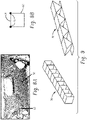
- Insert 24 can be made from a polymeric material and have a closed hollow profile (e.g., a sort of box shape) as illustrated in FIGS. 8A and 8B . As can be seen from FIG. 8B , the cavity forms a "box", wherein the insert ("lid") closes the box and the fixation points attach the lid to the box. Accordingly, insert 24 provides increased torsion stiffness and bending stiffness compared to ribs while also providing a lower weight than metallic or steel plates.
- a closed hollow profile e.g., a sort of box shape
- insert cover 44 can be positioned over the insert for aesthetic purposes. Since the insert 24 provides the structural integrity to the lift gate, the inert cover 44 can be attached to compensate for thermal expansion and contraction issues. In other words, the insert cover 44 can be a non-load bearing element (i.e., it bears its own load (weight), and does not provide further load bearing capabilities to the lift gate). In contrast, the insert 24 is a load bearing element which adds stiffness and structural integrity to the lift gate.
- outer cover 40 can be positioned over at least a portion of the lift gate. Outer cover 40 can be attached through adhesive or other suitable attachments. Outer cover 40 can be a single piece, or comprise multiple pieces. In addition, outer cover 40 can comprise a polymeric material. For example, outer cover 40 can comprise the same material as lift gate 1 and/ or insert 24, or a different polymeric material. In addition, when outer cover 40 comprises multiple pieces, the various pieces can comprise the same material. In the alternative, when outer cover 40 comprises multiple pieces, the various pieces can comprise different materials. Outer cover 40 can also include window 42. Window 42 can comprise glass of a polymeric material such as polycarbonate that can further reduce the overall weight of the lift gate structure. For example, window 42 can comprise a plastic glazing, commercially available through Exatec TM , LLC.
- FIGS. 4-8 illustrate a lift gate with a unitary body structure 45.
- body structure 45 includes top portion 50, bottom portion 52, first side portion 54, and second side portion 56.
- first side portion 52 and second side portion 54 can comprise a structural enhancement, such as ribs or webbing.
- top portion 50 and bottom portion 52 comprise a closed hollow profile 58.
- at least one side of top portion 50 and bottom portion 52 comprises an opening 60 or a plurality of openings 60, which provides accessibility for the entrance of media such as gas and fluids or cores and sliders.
- the closed hollow profiles can be manufactured through a variety of production techniques such as gas or water assisted injecting molding, collapsible cores, sliders, or over molded hollow steel inserts.
- Body structure 45 can be included in a lift gate between an inner and outer cover layer through the use of adhesive or other suitable attachment means. Stated differently, body structure 45 provides a frame for the lift gate.
- FIG. 9 illustrates both a closed hollow profile 70 and a cross ribbed C-profile 72.
- the closed hollow profile takes the shape of a box, while the cross ribbed C-profile is open at the face.
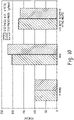
- the effectiveness of the closed hollow profile was simulated using FEA simulations (Hyperworks 11) and the results are illustrated in FIG. 10 . As shown in FIG. 10 , applying a lid fixed at some discrete points versus torsion ribs.
- FIGS. 11-12 illustrate a front end of a vehicle (e.g., a truck, bus, train, etc.) including front end module 101. As shown in FIG. 11 , front end module 101 is located below windshield 99 and above bumper 98.
- a vehicle e.g., a truck, bus, train, etc.
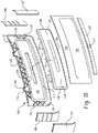
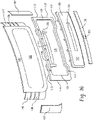
- FIGS. 13-16 are exploded views of the various components of front end module 101.
- front end module includes carrier 102, insert 130, and cover (also referred to as a mask) 140.
- Carrier 102 can include top portion 110, bottom portion 112, first side portion 114, and second side portion 116 that define a cavity 118.
- Cavity 118 can include upper cavity wall 119, first side cavity wall 121, second side cavity wall 123, and lower cavity wall 117. Cavity 118 can be of constant depth (the cavity walls are constant and equal) or of varying depth. The specific depth is dependent upon the desired structural integrity and the space available.
- Carrier 102 can include an optional opening 111 to allow air to pass through to a cooling system or other internal part of a vehicle.
- Carrier 102 can be mounted to the chassis (e.g., to the Body-In-White (BIW)) of a vehicle via hinges.
- hinges 105 can be attached to a rear surface of cavity 118 and upper portion 110, as shown in FIG. 16 .
- hinges 105 can be placed on the rear surface of upper portion 110.
- hinges 105 can be positioned on a rear surface of ribs 125 across upper portion 110.
- Ribs 125 can be located across at least a portion of top portion 110.
- Ribs 125 can be located across top portion 110 from first side portion 114 to second side portion 116.
- Ribs 125 can be located across top potion for greater than or equal to 50% of the distance from first side portion 114 to second side portion 116.
- ribs 125 can be attached to side portions 114 and 116 and be located at least a portion of the distance from top portion 110 to bottom portion 112.
- the ribs can be oriented perpendicular to the adjacent cavity wall, or can be oriented at an angle such that the ribs form triangular sections (e.g., that form equilateral triangles between the ribs and the adjacent walls).
- the ribs are located adjacent to the upper cavity wall 112.
- ribs can also be located adjacent to the 1 st and/or 2 nd cavity side walls.
- Corner wings 106 can be formed integral with carrier 102. As shown in FIG. 13 , corner wings 106 are located on the outer portions of carrier 102, outside of first and second side portions 114, 116, and extend from an outer edge of top portion 110 to an outer edge of bottom portion 112. Optionally, as shown in FIG. 15 , corner wings 106 can be a separate component, or can be formed integral with the carrier 102. As separate components, corner wings 106 can mounted onto the vehicle (e.g., via a hinge onto the chassis or the Body-In-White (BIW) of a vehicle). Hingedly attaching the corner wings 106 to the vehicle allows the corner wings 106 to be opened (e.g., away from carrier 102), thus allowing greater access to the vehicle and to more space for an operator (e.g., a mechanic or service provider).
- BIW Body-In-White
- corner wings 106 being formed as a separate component, is that a standard sized carrier 102 can be employed regardless of the size of the vehicle.
- a single sized carrier 102 can be used on a wide vehicle as well as a narrow vehicle, and different sized wings 106 can be used to ensure full coverage across the face of the two vehicles.
- Using a single sized carrier 102 can allow for a reduction in tooling and manufacturing costs and promote more efficient production.
- corner wings 106 can be formed integrally with cover 140. Corner wings 106 can be covered by corner fairings 107 which, as shown in FIG. 13 , can be completely separate components (e.g., not formed integrally with any other component).
- corner fairings 107 can be formed integrally with cover 140.
- Insert 130 can include base 133, which can be planar or slightly curved.
- Base 133 can include an opening 131 through which air can pass and can be aligned with opening 111 in carrier 102.
- Insert 130 can include upper wall 132, bottom wall 134, first side wall 136, and second side wall 138. All of the insert walls (e.g. upper wall 132, bottom wall 134, first side wall 136, and second side wall 138) can protrude away from base 133 toward carrier 102.
- insert 130 When joined together, insert 130 abuts carrier 102 and forms a closed hollow profile or "box shape."
- upper wall 132, bottom wall 134, first side wall 136 and second side wall 138 of insert 130 can abut top portion 110, bottom portion 112, first side portion 114, and second side portion 116 of carrier 102 to form a box structure.
- the box structure can have a depth approximately equal to the depth of cavity walls (117, 119,121, 123) combined with the depth of the insert walls (132, 134, 136, 138) protruding from base 133.
- insert walls (132, 134, 136, 138) can fit inside the cavity walls (117, 119,121, 123) such that the depth of the box structure is equal to the depth of the insert walls (132, 134, 136, 138).
- insert walls (132, 134, 136, 138) can include protrusions configured to mate with slots 109 to guide the joining of insert 130 and carrier 102 and form the closed hollow profile. Slots 109 can be located within cavity 118.
- Insert (130) and carrier (102) can be joined by a removable fastener, a permanent fastener, or a combination thereof.
- permanent fasteners include heat staking, or similar permanent fastener.
- Removable fasteners can include a clip, bolt, snap-fit connection, or similar removable attachment.
- Using clips and/or other removable elements can simplify tooling and/or enable ease of assembly.
- the openings and the clips can be designed for a snug fit (e.g., where the clip has a size that is only smaller than the opening inner diameter to enable insertion).
- the clips can have a size that enables transfer of loads to the insert (e.g., axially, e.g., from the sides of the clip).
- Slots 109 can be located all around carrier 102 surrounding cavity 118
- Cover 140 can be located over carrier 102 and insert 130. As shown in FIG. 13 , cover 140 can include first wing portion 146 and second wing portion 147 configured to cover at least a portion of corner wings 106. In addition, cover 140 can include corner fairings 107 integrally formed with cover 140, as shown in FIG. 14 . Cover 140 can include opening 142 configured to allow at least a portion of insert 130 to be visible. As shown in FIG. 16 , cover 140 can include corner wings 106. Cover 140 can be mounted directly to the Body-In-White (BIW) of a vehicle and include first side flange and second side flange for attachment with carrier 102.
- BAW Body-In-White
- a handle cover portion 150 can be included below cover 140.
- handle portion 150 can include a handle opening 151 to access a handle or other mechanism for opening front end module.
- polymeric materials include thermoplastic materials as well as combinations of thermoplastic materials with elastomeric materials and/or thermoset materials.
- Possible thermoplastic materials include polybutylene terephthalate (PBT); acrylonitrile-butadiene-styrene (ABS); polycarbonate (LEXAN TM and LEXAN TM EXL resins, commercially available from SABIC Innovative Plastics); polycarbonate/PBT blends; polycarbonate/ABS blends; copolycarbonate-polyesters; acrylic-styrene-acrylonitrile (ASA); acrylonitrile-(ethylene-polypropylene diamine modified)-styrene (AES); phenylene ether resins; blends of polyphenylene ether/polyamide (NORYL GTX TM resins, commercially available from SABIC Innovative Plastics); blends of polycarbonate/polyethylene terephthalate (PET)/PBT; polybutylene terephthalate and impact modifier (XE
- the fibers used for this application are long fibers, e.g., fibers having an aspect ratio (length/diameter) of greater than or equal to 10, specifically, greater than or equal to 50, more specifically, 50 to 500, and yet more specifically, 80 to 400.
- the diameter of the long fiber may range from 5 to 35 micrometers ( ⁇ m), specifically, 10 to 20 ⁇ m.
- the fibers can have a length, for example, of greater than or equal to 0.4 millimeter (mm), specifically, greater than or equal to 1 mm, more specifically, a length of greater than or equal to 2 mm.
- An exemplary filled resin is STAMAX TM resin, which is a long glass fiber filled polypropylene resin also commercially available from SABIC Innovative Plastics.
- Some possible reinforcing materials include fibers, such as glass, carbon, and so forth, as well as combinations comprising at least one of the foregoing; e.g., long glass fibers and/or long carbon fiber reinforced resins.
- the vehicle component can also be formed from combinations comprising at least one of any of the above-described materials.
- an insert e.g., a relatively flexible lid
- a cavity e.g., on an open, box-like shape
- permanent fixations e.g., heat stack, glue, etc.
- the fixations can be separate and discrete (e.g., the insert is not attached all the way around).
- the present design can combine a closed section geometry forming a hollow shape (e.g., in the bottom portion), e.g., to enhance bending and/or torsion stiffness, with ribbing (in the upper portion).
- a closed section geometry forming a hollow shape (e.g., in the bottom portion), e.g., to enhance bending and/or torsion stiffness, with ribbing (in the upper portion).
- ribbing in the upper portion.
- Below the window and lights can be a structural compartment formed by an insert and cavity, with an aesthetic over disposed over the structural compartment.
- the lift gate is only one example of a vehicle component that can comprise the closed section geometry which forms a hollow shape that provides bending and torsion stiffness in polymeric vehicle components.
- each of the top portion (10), the bottom portion (12), the first side portion (14), the second side portion (16); the insert (24); and the insert cover are formed either the same or a different polymeric material.
- the top portion (10), the bottom portion (12), the first side portion (14), the second side portion (16); the insert (24); and the insert cover are each formed from a material, and wherein the material is free of metal.
Landscapes
- Engineering & Computer Science (AREA)
- Mechanical Engineering (AREA)
- Chemical & Material Sciences (AREA)
- Combustion & Propulsion (AREA)
- Transportation (AREA)
- Architecture (AREA)
- Structural Engineering (AREA)
- Injection Moulding Of Plastics Or The Like (AREA)
- Body Structure For Vehicles (AREA)
Description
- This disclosure relates to a structural component of a vehicle such as a lift gate, and in particular, a polymeric vehicle component.
- Structural components for vehicles, such as front end modules and lift gates, can be loaded with torsion due to forces acting at separate locations. To accommodate this, high bending stiffness is desirable. For some applications, techniques such as injection molding and/or injection compression molding, such as with a given drawn direction and sliders, cannot provide desired and/or sufficient torsion stiffness.
US20110061302A1 is directed to an assembly having an opening panel of a motor vehicle and at least two reinforcing elements. Each reinforcing element has an elongate shape and two ends, the panel has at least two connecting elements, each reinforcing element being connectable to the panel in such a way that each end of the reinforcing elements is at least partially superposed on one of the connecting elements, the reinforcing elements and connecting elements forming at least one continuous frame when the reinforcing elements and the panel are connected. - Lift gates are provided to open or close an opening formed in a vehicle (e.g., at a rear portion of a hatch back type of passenger vehicle or the like). Front end modules are provided to allow access to components in the front of a vehicle, such as a truck. For example, components including cooling systems and oil and wiper fluids, and possibly other components (e.g., engine, radiator, heating, ventilation, and air conditioning systems) might be accessed through a front end module of a truck or bus. Because the weight of a vehicle body has an impact on the fuel consumption of the vehicle, attempts have been made to produce lift gates and front end modules from lighter-weight materials, such as polymeric materials, in an effort to reduce the overall weight of the vehicle. The use of polymeric materials reduces the overall weight, but in some applications may not accommodate stresses and strains placed on the lift gate or front end module. As an example, the lift gate or front end module may bend undesirably. This can displease a consumer. Worse yet, such flexure may fail to sufficiently resist deformation in a crash.
- Lift gates and front end modules are large component members of a vehicle body that rotate around a hinge when they open or close. Due to the level of stress from the repeated opening and closing of the components and the size of the components, they comprise a lot of metal (for structural integrity) and have ribs or steel inserts to ensure proper operation and structural stability. Other attempts to increase the stiffness and torsional rigidity include increasing the thickness of the panels. However, an increase of the panel thickness and/or the addition of the ribs for increasing the rigidity of the component also increases the overall weight of the component, which can negatively affect the fuel efficiency of the vehicle. Furthermore, the use of reinforcements, such as ribs, can affect the ability to efficiently run wires, cables, or the like through the component. In addition, ribs and other reinforcements negatively impact the aesthetic quality of the component because such features can leave visible imperfections on the panels, thus requiring an additional panel to be installed to provide a finished appearance. The use of steel or other materials in combination with a plastic component can also add manufacturing time and expense to the production of the vehicle component.
- Accordingly, a need exists for a light-weight vehicle component with high torsional and bending stiffness without diminishing the functional and/or aesthetic quality of the component.
- Disclosed herein are vehicle components, such as lift gates and front end modules, and vehicles comprising the same. The invention is as set out in the appended set of claims.
- In an embodiment, a vehicle component for a vehicle can comprise: a carrier comprising a top portion, a bottom portion, a first side portion, and a second side portion; a cavity, wherein the cavity comprises a bottom cavity wall, cavity side walls, and a top portion of the cavity having an upper cavity wall; an insert covering at least a portion of the cavity and attached to the upper cavity wall the bottom cavity wall, and/or the cavity side walls; and a cover attached to the carrier.
- The above described and other features are exemplified by the following figures and detailed description.
- Refer now to the figures, which are exemplary embodiments, and wherein the like elements are numbered alike.
-
FIG. 1 is a rear view of the inner portion of a lift gate. -
FIG. 2 is a rear view of the inner portion of the lift gate ofFIG. 1 with a closed hollow profile insert. -
FIG. 3 is a rear view of the lift gate ofFIGS. 1 and2 with an outer cover. -
FIG. 4 is a rear view of a lift gate. -
FIG. 5 is a cross sectional view of the top portion of the lift gate ofFIG. 4 taken along line A-A. -
FIG. 6 is a cross sectional view of the bottom portion of the lift gate ofFIG. 4 taken along line A-A. -
FIG. 7 is a rear view of the top portion of the lift gate ofFIG. 4 . -
FIG. 8A is a rear view of the bottom portion of the lift gate ofFIG. 4 . -
FIG. 8B is an illustration of the essentially box type shape formed by the closed hollow profile. -
FIG. 9 is a side-by-side comparison of a closed hollow profile and a cross ribbed C-profile. -
FIG. 10 is a chart illustrating the relative torsion stiffness and stiffness per mass for the profiles ofFIG. 9 . -
FIG. 11 is a front view of an embodiment of a truck including a front end module. -
FIG. 12 is a partial front view of an embodiment of a truck including a front end module. -
FIG. 13 is an exploded view of an embodiment of a front end module. -
FIG. 14 is an exploded view of an embodiment of a front end module. -
FIG. 15 is an exploded view of another embodiment of a front end module. -
FIG. 16 is an exploded view of another embodiment of a front end module. - Disclosed herein is a structural component of a vehicle such as a lift gate, a front end module, a door, and other structural components that have bending and torsional stiffness needs, in particular, a polymeric vehicle component comprising portions and/or inserts with a closed hollow profile to improve bending and torsional stiffness. Without being bound by theory, it is believed that the favorable results obtained herein, e.g., a light-weight vehicle component with optimal bending and torsion stiffness and increased torsion per mass, can be achieved using a closed hollow shape profile integrated into a portion of the vehicle component.
- The term "vehicle component" as used herein can refer to a lift gate, door module, front end module, and other components such as, but not limited to instrument panel carriers, and bumper claddings of a vehicle structure. As illustrated in the figures and discussed below, a lift gate will be used as an exemplary vehicle component for
FIGS. 1-8 , and a front end module will be used as an exemplary vehicle component forFIGS. 11-16 . However, the embodiments discussed below can be applied to other vehicle components as mentioned above. - A lift gate is a rear portion of a vehicle designed to open the rear of the vehicle, e.g. a hatchback. A front end module is a portion of a front of a vehicle, such as a truck, bus, or the like, that is designed to open to allow access to internal components of the truck. For example, a front end module can provide access to vehicle systems, e.g., cooling systems, oil, wiper fluid, etc. Due to their relative size, lift gates and front end modules can be subjected to high levels of torsion and bending. However, efforts to increase the torsion and bending stiffness, such as the use of steel panels, ribs, and/or additional materials, have yielded additional problems including added weight, production costs, and aesthetic issues. It was found that using a closed hollow profile in specific areas of a vehicle component (e.g., polymeric lift gate and a polymeric front end module) provided superior torsion and bending stiffness without the aforementioned deficiencies.
-
FIG. 1 is a rear view of an inner portion of lift gate 1. As illustrated inFIG. 1 , lift gate 1 comprises carrier formed from atop portion 10,bottom portion 12,first side portion 14, andsecond side portion 16. Lift gate 1 can include window opening 30 located belowtop portion 10 and abovebottom portion 12.Top portion 10,first side portion 14, andsecond side portion 14 can includeribs 25.Bottom portion 12 can includecavity 18. -
Cavity 18 can extend horizontally fromfirst side portion 14 tosecond side portion 16 and can be bound by firstcavity side wall 21 and secondcavity side wall 23.Cavity 18 can also extend vertically from a bottom edge ofbottom portion 12 to a point belowwindow opening 30. The specific size of the cavity will depend upon the particular vehicle design.Cavity 18 is defined in a vertical direction byupper cavity wall 19 andlower cavity wall 17. As shown inFIG. 1 ,upper cavity wall 19 can include a plurality of openings to accommodate a connection mechanism, discussed in further detail below. In addition,upper cavity wall 19 can have anopening 20 to receive the attachment from theinsert 24.Lower cavity wall 17 can include anarea 22, which serves to compress the water seal which is usually mounted to the body in white (BIW). - As shown in
FIG. 2 , insert 24 is shaped to substantially fillcavity 18 so as to provide an interference fit with the cavity walls. For example, insert 24 can abutupper cavity wall 19 andlower cavity wall 17, thereby preventing movement ofinsert 24 in a vertical direction. In addition, insert 24 can abut firstcavity side wall 21 and secondcavity side wall 23. During attachment, insert 24 can be placed withincavity 18 by forcing the top surface ofinsert 24 beyondlip 20 by temporarily deforminglip 20 such thatlip 20 returns to its original shape and position afterinsert 24 is in place. Thus,lip 20 can help retaininsert 24 in a proper location. -
Insert 24 can be attached to lift gate 1 by removable (i.e., without damage to the vehicle component) or permanent attachment (i.e., not removable). For example, upper cavity wall can include plurality of openings sized to receive a plurality offirst attachment mechanisms 26 located on or attached to the top surface ofinsert 24 in the form of a clip, bolt, snap-fit connection, or similar removable attachment. Using clips and/or other removable elements can simplify tooling and/or enable ease of assembly. For the removable elements it is desirable that they prevent relative motion between the insert and the cavity in-plane of the insert as to get maximum torsion stiffening. Therefore, the openings and the clips can be designed for a snug fit (e.g., where the clip has a size that is only smaller than the opening inner diameter to enable insertion). In other words, the clips can have a size that enables transfer of loads to the insert (e.g., axially, e.g., from the sides of the clip). It is further noted, that the openings are illustrated along an upper cavity wall, but are not limited to such location. Openings can be located all around the cavity or in portions of the cavity. The specific location is dependent upon design restrictions and not mandatory that clips should be at the top and that the permanent fixations (e.g., heat stakes) should be at the bottom. Hence, the fixations can be any combination of permanent and removable (wherein removable means without damage to the vehicle component), depending upon the desired design criteria and forming (e.g., molding) constraints. In addition, the bottom ofinsert 24 can be attached to thelower cavity wall 17 and/orrecess 22 through asecond attachment mechanism 28, such as heat staking or other permanent attachment features as well as any removable fixation elements mentioned above. Heat staking is the process of melting and reforming a thermoplastic stud to lock elements together mechanically. - As is seen in
FIGS. 1 and2 , thecavity 18 can be located in thelower portion 12 of the lift gate. Optionally, thecavity 18 does not extend to the edge of the lower portion, it occupies less than all of the lower portion. For example, the cavity can be located over greater than or equal to 50% of the lower portion, for example, over 60% to 90% of the lower portion. In other words, theupper cavity wall 19 can form the top of thelower portion 12, thelower cavity wall 17 can form the bottom of thelower portion 12, such that the cavity extends from the top to the bottom of thelower portion 12. However, the firstcavity side wall 21 and/or the secondcavity side wall 23 form the two sides of the lower portion. In other words, thecavity 18 does not extend from one side of the lower portion to the other side of the lower portion. Hence, the lower portion can have an area that extends beyond at least one side of thecavity 18, for example, that extends beyond at least two walls of thecavity 18, such that when theinsert 24 is located over thecavity 18, the insert does not extend to the periphery or a lip of thelower portion 12 on all sides. The insert can be spaced apart from the periphery (or lip) of thelower portion 12 on a side, for example, on two opposite sides. - As is further illustrated in
FIGS. 1 and2 , the lower portion can comprise thecavity 18 andinsert 24, while the upper portion can compriseribs 25. Theribs 25 can optionally be triangular and can be overlapping, as desired. Optionally, the cavity is free of ribs. Optionally, the bottom portion is free of ribs. In other words, the portion of the lift gate that is below the lights and below the window, can be free of ribs, while above the lights and above and around the window can be ribbing. -
Insert 24 can be made from a polymeric material and have a closed hollow profile (e.g., a sort of box shape) as illustrated inFIGS. 8A and 8B . As can be seen fromFIG. 8B , the cavity forms a "box", wherein the insert ("lid") closes the box and the fixation points attach the lid to the box. Accordingly, insert 24 provides increased torsion stiffness and bending stiffness compared to ribs while also providing a lower weight than metallic or steel plates. - As shown in
FIG. 3 , insertcover 44 can be positioned over the insert for aesthetic purposes. Since theinsert 24 provides the structural integrity to the lift gate, theinert cover 44 can be attached to compensate for thermal expansion and contraction issues. In other words, theinsert cover 44 can be a non-load bearing element (i.e., it bears its own load (weight), and does not provide further load bearing capabilities to the lift gate). In contrast, theinsert 24 is a load bearing element which adds stiffness and structural integrity to the lift gate. - Furthermore,
outer cover 40 can be positioned over at least a portion of the lift gate.Outer cover 40 can be attached through adhesive or other suitable attachments.Outer cover 40 can be a single piece, or comprise multiple pieces. In addition,outer cover 40 can comprise a polymeric material. For example,outer cover 40 can comprise the same material as lift gate 1 and/ or insert 24, or a different polymeric material. In addition, whenouter cover 40 comprises multiple pieces, the various pieces can comprise the same material. In the alternative, whenouter cover 40 comprises multiple pieces, the various pieces can comprise different materials.Outer cover 40 can also includewindow 42.Window 42 can comprise glass of a polymeric material such as polycarbonate that can further reduce the overall weight of the lift gate structure. For example,window 42 can comprise a plastic glazing, commercially available through Exatec™, LLC. -
FIGS. 4-8 illustrate a lift gate with a unitary body structure 45. As shown inFIG. 4 , body structure 45 includestop portion 50,bottom portion 52,first side portion 54, andsecond side portion 56. Optionally,first side portion 52 andsecond side portion 54 can comprise a structural enhancement, such as ribs or webbing. As illustrated inFIGS. 5 and 6 ,top portion 50 andbottom portion 52 comprise a closedhollow profile 58. In addition, as shown inFIGS. 7 and8 , at least one side oftop portion 50 andbottom portion 52 comprises anopening 60 or a plurality ofopenings 60, which provides accessibility for the entrance of media such as gas and fluids or cores and sliders. Accordingly, the closed hollow profiles can be manufactured through a variety of production techniques such as gas or water assisted injecting molding, collapsible cores, sliders, or over molded hollow steel inserts. Body structure 45 can be included in a lift gate between an inner and outer cover layer through the use of adhesive or other suitable attachment means. Stated differently, body structure 45 provides a frame for the lift gate. -
FIG. 9 illustrates both a closedhollow profile 70 and a cross ribbed C-profile 72. As shown inFIG. 9 , the closed hollow profile takes the shape of a box, while the cross ribbed C-profile is open at the face. The effectiveness of the closed hollow profile was simulated using FEA simulations (Hyperworks 11) and the results are illustrated inFIG. 10 . As shown inFIG. 10 , applying a lid fixed at some discrete points versus torsion ribs. -
FIGS. 11-12 illustrate a front end of a vehicle (e.g., a truck, bus, train, etc.) includingfront end module 101. As shown inFIG. 11 ,front end module 101 is located belowwindshield 99 and abovebumper 98. -
FIGS. 13-16 are exploded views of the various components offront end module 101. As shown inFIG. 13 , front end module includescarrier 102, insert 130, and cover (also referred to as a mask) 140.Carrier 102 can includetop portion 110,bottom portion 112,first side portion 114, andsecond side portion 116 that define acavity 118.Cavity 118 can includeupper cavity wall 119, firstside cavity wall 121, secondside cavity wall 123, andlower cavity wall 117.Cavity 118 can be of constant depth (the cavity walls are constant and equal) or of varying depth. The specific depth is dependent upon the desired structural integrity and the space available. -
Carrier 102 can include anoptional opening 111 to allow air to pass through to a cooling system or other internal part of a vehicle.Carrier 102 can be mounted to the chassis (e.g., to the Body-In-White (BIW)) of a vehicle via hinges. For example, hinges 105 can be attached to a rear surface ofcavity 118 andupper portion 110, as shown inFIG. 16 . In the alternative, hinges 105 can be placed on the rear surface ofupper portion 110. In addition, hinges 105 can be positioned on a rear surface ofribs 125 acrossupper portion 110. -
Ribs 125 can be located across at least a portion oftop portion 110. For example,ribs 125 can be located acrosstop portion 110 fromfirst side portion 114 tosecond side portion 116.Ribs 125 can be located across top potion for greater than or equal to 50% of the distance fromfirst side portion 114 tosecond side portion 116. In addition,ribs 125 can be attached toside portions top portion 110 tobottom portion 112. The ribs can be oriented perpendicular to the adjacent cavity wall, or can be oriented at an angle such that the ribs form triangular sections (e.g., that form equilateral triangles between the ribs and the adjacent walls). Desirably, the ribs are located adjacent to theupper cavity wall 112. Optionally, ribs can also be located adjacent to the 1st and/or 2nd cavity side walls. -
Corner wings 106 can be formed integral withcarrier 102. As shown inFIG. 13 ,corner wings 106 are located on the outer portions ofcarrier 102, outside of first andsecond side portions top portion 110 to an outer edge ofbottom portion 112. Optionally, as shown inFIG. 15 ,corner wings 106 can be a separate component, or can be formed integral with thecarrier 102. As separate components,corner wings 106 can mounted onto the vehicle (e.g., via a hinge onto the chassis or the Body-In-White (BIW) of a vehicle). Hingedly attaching thecorner wings 106 to the vehicle allows thecorner wings 106 to be opened (e.g., away from carrier 102), thus allowing greater access to the vehicle and to more space for an operator (e.g., a mechanic or service provider). - A further advantage of the
corner wings 106 being formed as a separate component, is that a standardsized carrier 102 can be employed regardless of the size of the vehicle. For example, a singlesized carrier 102 can be used on a wide vehicle as well as a narrow vehicle, and differentsized wings 106 can be used to ensure full coverage across the face of the two vehicles. Using a singlesized carrier 102 can allow for a reduction in tooling and manufacturing costs and promote more efficient production. As shown inFIG. 16 ,corner wings 106 can be formed integrally withcover 140.Corner wings 106 can be covered bycorner fairings 107 which, as shown inFIG. 13 , can be completely separate components (e.g., not formed integrally with any other component). In the alternative, as shown inFIG. 14 ,corner fairings 107 can be formed integrally withcover 140. -
Insert 130 can includebase 133, which can be planar or slightly curved.Base 133 can include anopening 131 through which air can pass and can be aligned with opening 111 incarrier 102.Insert 130 can includeupper wall 132,bottom wall 134,first side wall 136, andsecond side wall 138. All of the insert walls (e.g.upper wall 132,bottom wall 134,first side wall 136, and second side wall 138) can protrude away frombase 133 towardcarrier 102. When joined together, insert 130 abutscarrier 102 and forms a closed hollow profile or "box shape." For example,upper wall 132,bottom wall 134,first side wall 136 andsecond side wall 138 ofinsert 130 can abuttop portion 110,bottom portion 112,first side portion 114, andsecond side portion 116 ofcarrier 102 to form a box structure. The box structure can have a depth approximately equal to the depth of cavity walls (117, 119,121, 123) combined with the depth of the insert walls (132, 134, 136, 138) protruding frombase 133. The insert walls (132, 134, 136, 138) can fit inside the cavity walls (117, 119,121, 123) such that the depth of the box structure is equal to the depth of the insert walls (132, 134, 136, 138). In addition, insert walls (132, 134, 136, 138) can include protrusions configured to mate withslots 109 to guide the joining ofinsert 130 andcarrier 102 and form the closed hollow profile.Slots 109 can be located withincavity 118. - Insert (130) and carrier (102) can be joined by a removable fastener, a permanent fastener, or a combination thereof. Examples of permanent fasteners include heat staking, or similar permanent fastener. Removable fasteners can include a clip, bolt, snap-fit connection, or similar removable attachment. Using clips and/or other removable elements can simplify tooling and/or enable ease of assembly. For the removable elements it is desirable that they prevent relative motion between the insert and the cavity in-plane of the insert as to get maximum torsion stiffening. Therefore, the openings and the clips can be designed for a snug fit (e.g., where the clip has a size that is only smaller than the opening inner diameter to enable insertion). In other words, the clips can have a size that enables transfer of loads to the insert (e.g., axially, e.g., from the sides of the clip).
Slots 109 can be located all aroundcarrier 102 surroundingcavity 118 - Cover 140 can be located over
carrier 102 and insert 130. As shown inFIG. 13 ,cover 140 can includefirst wing portion 146 andsecond wing portion 147 configured to cover at least a portion ofcorner wings 106. In addition,cover 140 can includecorner fairings 107 integrally formed withcover 140, as shown inFIG. 14 . Cover 140 can include opening 142 configured to allow at least a portion ofinsert 130 to be visible. As shown inFIG. 16 ,cover 140 can includecorner wings 106. Cover 140 can be mounted directly to the Body-In-White (BIW) of a vehicle and include first side flange and second side flange for attachment withcarrier 102. - A
handle cover portion 150 can be included belowcover 140. For example, as shown inFIG. 16 ,handle portion 150 can include ahandle opening 151 to access a handle or other mechanism for opening front end module. - Examples of polymeric materials include thermoplastic materials as well as combinations of thermoplastic materials with elastomeric materials and/or thermoset materials. Possible thermoplastic materials include polybutylene terephthalate (PBT); acrylonitrile-butadiene-styrene (ABS); polycarbonate (LEXAN™ and LEXAN™ EXL resins, commercially available from SABIC Innovative Plastics); polycarbonate/PBT blends; polycarbonate/ABS blends; copolycarbonate-polyesters; acrylic-styrene-acrylonitrile (ASA); acrylonitrile-(ethylene-polypropylene diamine modified)-styrene (AES); phenylene ether resins; blends of polyphenylene ether/polyamide (NORYL GTX™ resins, commercially available from SABIC Innovative Plastics); blends of polycarbonate/polyethylene terephthalate (PET)/PBT; polybutylene terephthalate and impact modifier (XENOY™ resins, commercially available from SABIC Innovative Plastics); polyamides; phenylene sulfide resins; polyvinyl chloride PVC; high impact polystyrene (HIPS); low/high density polyethylene (L/HDPE); polypropylene (PP); expanded polypropylene (EPP); polyethylene and fiber composites; polypropylene and fiber composites; long fiber reinforced thermoplastics (VERTON™ resins, commercially available from SABIC Innovative Plastics) and thermoplastic olefins (TPO), as well as combinations comprising at least one of the foregoing.
- Generally, the fibers used for this application are long fibers, e.g., fibers having an aspect ratio (length/diameter) of greater than or equal to 10, specifically, greater than or equal to 50, more specifically, 50 to 500, and yet more specifically, 80 to 400. For example, the diameter of the long fiber may range from 5 to 35 micrometers (µm), specifically, 10 to 20 µm. The fibers can have a length, for example, of greater than or equal to 0.4 millimeter (mm), specifically, greater than or equal to 1 mm, more specifically, a length of greater than or equal to 2 mm.
- An exemplary filled resin is STAMAX™ resin, which is a long glass fiber filled polypropylene resin also commercially available from SABIC Innovative Plastics. Some possible reinforcing materials include fibers, such as glass, carbon, and so forth, as well as combinations comprising at least one of the foregoing; e.g., long glass fibers and/or long carbon fiber reinforced resins. The vehicle component can also be formed from combinations comprising at least one of any of the above-described materials.
- In the present lift gate design, adding an insert (e.g., a relatively flexible lid) structure on a cavity (e.g., on an open, box-like shape), fixed at a number of points either removably (e.g., by clips), or by permanent fixations (e.g., heat stack, glue, etc.) attains greater stiffness overweight compared to classical molded solutions (e.g., ribbing). Herein the fixations can be separate and discrete (e.g., the insert is not attached all the way around).
- The present design can combine a closed section geometry forming a hollow shape (e.g., in the bottom portion), e.g., to enhance bending and/or torsion stiffness, with ribbing (in the upper portion). In other words, around the window and/or above the lights there can be ribbing, while below the window and lights the lift gate can be free of ribbing. Below the window and lights can be a structural compartment formed by an insert and cavity, with an aesthetic over disposed over the structural compartment.
- It is noted that the lift gate is only one example of a vehicle component that can comprise the closed section geometry which forms a hollow shape that provides bending and torsion stiffness in polymeric vehicle components.
- In an example, each of the top portion (10), the bottom portion (12), the first side portion (14), the second side portion (16); the insert (24); and the insert cover are formed either the same or a different polymeric material.
- In an example, the top portion (10), the bottom portion (12), the first side portion (14), the second side portion (16); the insert (24); and the insert cover are each formed from a material, and wherein the material is free of metal.
Claims (15)
- A vehicle component for a vehicle comprising:a top portion (10,110), a bottom portion (12,112), a first side portion (14,114), and a second side portion (16,116), preferably wherein a window opening (30) is located below the top portion (10,110) and above the bottom portion (12,112);wherein the bottom portion (12,112) defines a cavity (18,118), wherein the cavity (18,118) comprises a bottom cavity wall (17,117), cavity side walls (21,23,121,123), and a top portion of the cavity (18,118) having an upper cavity wall (19,119);an insert (24,130) located within the cavity (18,118) and attached to the upper cavity wall (19,119), the bottom cavity wall (17,117), and/or the cavity side walls (21,23,121,123), wherein the insert (24,130) is a load bearing element; andan insert cover (44) attached over the insert, on a side of the insert (24,130) opposite the cavity (18,118), wherein the insert cover (44) is a non-load bearing element,wherein the vehicle component is a lift gate (1) which provides access to a rear of the vehicle or wherein the vehicle component is a front end module (101) which provides access to a front of the vehicle, characterized in that the insert (24, 130) covers the cavity (18, 118) as a lid.
- The vehicle component of Claim 1, wherein each of the top portion (10,110), the bottom portion (12,112), the first side portion (14,114), the second side portion (16,116); the insert (24,130); and the insert cover (44) are formed either the same or a different polymeric material, preferably wherein these components are free of metal.
- The vehicle component of any of the preceding claims, wherein the insert (24,130) is attached to the cavity (18,118) with a first attachment mechanism (26), wherein the insert (24,130) is removably attached.
- The vehicle component of any of the preceding claims, wherein the insert (24,130) is attached to the cavity (18,118) with a second attachment mechanism (28), wherein the second attachment mechanism (28) is a permanent attachment, and wherein the second attachment mechanism (28) comprises a heat stake.
- The vehicle component of any of the preceding claims, wherein the cavity (18,118) extends from the first side portion (14,114) to the second side portion (16,116) and wherein the insert (24) abuts the upper cavity wall (19,119), the bottom cavity wall (17,117), and the cavity side walls (21,23,121,123).
- The vehicle component of any of the preceding claims, wherein the insert (24,130) is a polymeric material and wherein the polymeric material comprises long glass fiber filled polypropylene.
- The vehicle component of any of the preceding claims, wherein at least one of the first side portion (14,114), the second side portion (16,116), and the top portion (10,110) comprises ribs (25).
- The vehicle component of any of the preceding claims, wherein the insert (24,130) comprises a channel (29) sized to accommodate a cable.
- The vehicle component of any of the preceding claims, wherein the cavity (18,118) occupies 60% to 90% of the distance from the first side portion (14,114) to the second side portion (16,116).
- The vehicle component of any of the preceding claims, wherein the cavity (18,118) is free of ribbing.
- The vehicle component of any of the preceding claims, further comprising a window opening (30) located below the top portion (10,110) and above the cavity (18,118).
- The vehicle component of Claim 11, wherein below the window opening (30), the lift gate (1) is free of ribbing.
- The vehicle component of Claim 12, wherein the lift gate (1) has ribbing (25) above the window opening (30) and to the sides of the window opening (30).
- A vehicle comprising: a structural body and the vehicle component of any of the preceding claims.
- A method for making the vehicle component of any of the preceding claims for a vehicle comprising: forming the vehicle component via a molding process, wherein the molding process uses media, and wherein the media comprises at least one of fluids and cores and sliders.
Applications Claiming Priority (4)
| Application Number | Priority Date | Filing Date | Title |
|---|---|---|---|
| US201361887687P | 2013-10-07 | 2013-10-07 | |
| US201461935718P | 2014-02-04 | 2014-02-04 | |
| PCT/IB2014/065127 WO2015052655A1 (en) | 2013-10-07 | 2014-10-07 | Closed section geometry, hollow shape, vehicle components |
| EP14799541.9A EP3055150B1 (en) | 2013-10-07 | 2014-10-07 | Closed section geometry, hollow shape, vehicle components |
Related Parent Applications (2)
| Application Number | Title | Priority Date | Filing Date |
|---|---|---|---|
| EP14799541.9A Division EP3055150B1 (en) | 2013-10-07 | 2014-10-07 | Closed section geometry, hollow shape, vehicle components |
| EP14799541.9A Division-Into EP3055150B1 (en) | 2013-10-07 | 2014-10-07 | Closed section geometry, hollow shape, vehicle components |
Publications (2)
| Publication Number | Publication Date |
|---|---|
| EP3756919A1 EP3756919A1 (en) | 2020-12-30 |
| EP3756919B1 true EP3756919B1 (en) | 2022-06-01 |
Family
ID=51903959
Family Applications (2)
| Application Number | Title | Priority Date | Filing Date |
|---|---|---|---|
| EP14799541.9A Active EP3055150B1 (en) | 2013-10-07 | 2014-10-07 | Closed section geometry, hollow shape, vehicle components |
| EP20182574.2A Active EP3756919B1 (en) | 2013-10-07 | 2014-10-07 | Closed section geometry, hollow shape, vehicle components |
Family Applications Before (1)
| Application Number | Title | Priority Date | Filing Date |
|---|---|---|---|
| EP14799541.9A Active EP3055150B1 (en) | 2013-10-07 | 2014-10-07 | Closed section geometry, hollow shape, vehicle components |
Country Status (5)
| Country | Link |
|---|---|
| US (1) | US9981534B2 (en) |
| EP (2) | EP3055150B1 (en) |
| KR (1) | KR102374628B1 (en) |
| CN (2) | CN105636810B (en) |
| WO (1) | WO2015052655A1 (en) |
Families Citing this family (26)
| Publication number | Priority date | Publication date | Assignee | Title |
|---|---|---|---|---|
| JP6436021B2 (en) * | 2015-08-31 | 2018-12-12 | トヨタ自動車株式会社 | Resin panel structure for vehicles and luggage door |
| CN108136633B (en) | 2015-09-07 | 2021-02-05 | 沙特基础工业全球技术公司 | Lighting system with plastic glass rear baffle |
| WO2017042698A1 (en) | 2015-09-07 | 2017-03-16 | Sabic Global Technologies B.V. | Surfaces of plastic glazing of tailgates |
| CN108025624B (en) | 2015-09-07 | 2021-04-27 | 沙特基础工业全球技术公司 | Plastic glazing for the tailgate of a vehicle |
| CN108025469B (en) | 2015-09-07 | 2020-12-25 | 沙特基础工业全球技术公司 | Plastic glass forming of tailgate |
| KR102215029B1 (en) | 2015-11-23 | 2021-02-15 | 사빅 글로벌 테크놀러지스 비.브이. | Lighting system for windows having plastic glazing |
| EP3257694B1 (en) | 2016-06-16 | 2020-05-06 | C.R.F. Società Consortile per Azioni | Hatchback door for motor-vehicles |
| CN106114162A (en) * | 2016-07-29 | 2016-11-16 | 奇瑞新能源汽车技术有限公司 | A kind of automotive back door license plate lamp mounting structure |
| US10650621B1 (en) | 2016-09-13 | 2020-05-12 | Iocurrents, Inc. | Interfacing with a vehicular controller area network |
| USD886010S1 (en) | 2016-09-27 | 2020-06-02 | Sabic Global Technologies B.V. | Fairing with flow channels |
| USD894067S1 (en) | 2016-10-14 | 2020-08-25 | Sabic Global Technologies B.V. | Roof fairing |
| EP3548320B1 (en) * | 2016-12-01 | 2022-12-07 | SABIC Global Technologies B.V. | Hybrid composite tailgate |
| EP3381771B1 (en) | 2017-03-27 | 2021-03-24 | SABIC Global Technologies B.V. | Integrated vehicle hood |
| JP6966314B2 (en) * | 2017-12-19 | 2021-11-17 | トヨタ自動車株式会社 | Vehicle resin back door and its manufacturing method |
| CN107985034A (en) * | 2017-12-29 | 2018-05-04 | 常熟市汽车饰件股份有限公司 | The injection tail-gate and vehicle of vehicle |
| FR3083484B1 (en) * | 2018-07-05 | 2021-04-09 | Renault Sas | VEHICLE BOX DOOR STRUCTURE DEVICE |
| US11305822B2 (en) * | 2018-11-27 | 2022-04-19 | Magna Exteriors, Inc. | Liftgate arrangement having a carbon fiber reinforced sheet molding compound reinforcement |
| US11034219B2 (en) | 2019-01-25 | 2021-06-15 | Toyota Motor Engineering & Manufacturing North America, Inc. | Vehicle doors including torsion bar support assemblies and methods for assembling the same |
| US10717349B1 (en) | 2019-01-29 | 2020-07-21 | Toyota Motor Engineering & Manufacturing North America, Inc. | Vehicle doors including torsion bar support assemblies |
| JP7429175B2 (en) * | 2020-09-16 | 2024-02-07 | ダイハツ工業株式会社 | Deformation amount prediction method |
| US12103370B2 (en) * | 2021-06-29 | 2024-10-01 | Magna Exteriors Inc. | Liftgate with bulkhead reinforcements |
| JP7685907B2 (en) * | 2021-08-18 | 2025-05-30 | ダイキョーニシカワ株式会社 | Vehicle back door |
| FR3127726B1 (en) * | 2021-10-01 | 2025-07-18 | Cie Plastic Omnium Se | Motor vehicle opening fitted with an equipment support plate and a removable skin |
| FR3127725B1 (en) * | 2021-10-01 | 2025-07-18 | Cie Plastic Omnium Se | Motor vehicle opening fitted with a removable equipment support plate and skin |
| JP7800284B2 (en) * | 2022-04-25 | 2026-01-16 | マツダ株式会社 | Vehicle back door structure |
| CN115180026B (en) * | 2022-08-05 | 2023-07-11 | 上汽大众汽车有限公司 | Composite engine cover and manufacturing method thereof |
Citations (2)
| Publication number | Priority date | Publication date | Assignee | Title |
|---|---|---|---|---|
| DE202004011851U1 (en) * | 2004-07-28 | 2004-09-30 | Peguform Gmbh & Co. Kg | Automotive rear door |
| EP1120303B1 (en) * | 2000-01-26 | 2007-09-05 | Inoplast | Plastic motor vehicle door and vehicle with such a door |
Family Cites Families (82)
| Publication number | Priority date | Publication date | Assignee | Title |
|---|---|---|---|---|
| US4083903A (en) | 1974-10-18 | 1978-04-11 | California Injection Molding Co., Inc. | Method for molding elongated thin wall articles |
| US4403399A (en) * | 1981-09-28 | 1983-09-13 | Harris Corporation | Method of fabricating a vertical fuse utilizing epitaxial deposition and special masking |
| DE3637622A1 (en) * | 1986-11-05 | 1988-05-19 | Ford Werke Ag | DOUBLE-WALLED PLASTIC BODY COMPONENT FOR MOTOR VEHICLES |
| US4965028A (en) | 1987-09-04 | 1990-10-23 | Galic/Maus Ventures | Method of injection molding thermoplastic through multiple gates |
| JPH01129052A (en) | 1987-11-13 | 1989-05-22 | Mitsubishi Petrochem Co Ltd | Reinforced modified propylene resin composition |
| KR930019643A (en) | 1991-06-27 | 1993-10-18 | 크누트 샤우에르테, 클라우스 대너 | 2- (4-substituted phenylhydrazino) -2-thiazoline and 2- (4-substituted phenylazo) -2-thiazoline, methods for their preparation and their use to rescue external parasitic layers |
| JPH07112457A (en) | 1993-10-20 | 1995-05-02 | Mitsubishi Rayon Co Ltd | Injection molding mold and injection molding method |
| JP4033503B2 (en) | 1996-05-24 | 2008-01-16 | スリーエム カンパニー | Spray adhesive |
| JPH09314614A (en) | 1996-05-31 | 1997-12-09 | Toyota Motor Corp | Injection molding method |
| US5799991A (en) | 1996-10-23 | 1998-09-01 | Concept Analysis Corporation | Molded bumper system with reinforcement beam |
| JP3784497B2 (en) | 1997-05-29 | 2006-06-14 | 三菱エンジニアリングプラスチックス株式会社 | Thermoplastic resin glazing material and method for producing the same |
| JPH1110673A (en) | 1997-06-24 | 1999-01-19 | Idemitsu Petrochem Co Ltd | Laminated molding method and laminated molded product of fiber reinforced resin |
| US6157416A (en) | 1998-01-13 | 2000-12-05 | Mitsubishi Consumer Electronics America, Inc. | Advanced projection television screen |
| JP3992349B2 (en) | 1998-02-12 | 2007-10-17 | 日本ポリプロ株式会社 | Propylene resin composition |
| JPH11333883A (en) | 1998-05-29 | 1999-12-07 | Miyagawa Kasei Ind Co Ltd | Injection molding method and mold for injection molding |
| JP4509239B2 (en) | 1998-11-19 | 2010-07-21 | ダイセル化学工業株式会社 | Cellulose triacetate and method for producing the same |
| JP2000239437A (en) | 1999-02-19 | 2000-09-05 | Idemitsu Petrochem Co Ltd | Glass fiber-containing material for expansion molding, expansion molding process and expansion molded product |
| JP2001018654A (en) | 1999-07-02 | 2001-01-23 | Yazaki Corp | Automotive door module base |
| JP2001277851A (en) | 2000-03-31 | 2001-10-10 | Fujikura Ltd | Car door structure |
| FR2808764B1 (en) * | 2000-05-11 | 2002-08-09 | Valeo Systemes Dessuyage | EQUIPMENT MODULE FOR A MOTOR VEHICLE OPENING ELEMENT |
| DE10100914A1 (en) * | 2001-01-11 | 2002-07-18 | Bayer Ag | Plate-shaped lightweight component |
| US20030110705A1 (en) * | 2001-12-13 | 2003-06-19 | Carlisle Engineered Products | Plastic double-walled structural panel |
| WO2003092984A1 (en) | 2002-04-30 | 2003-11-13 | G P Daikyo Corporation | Resinous interior member of opening/closing body, mold therefor and method of molding the same |
| KR100932641B1 (en) * | 2003-07-07 | 2009-12-21 | 한라공조주식회사 | Carrier of Vehicle Front End Module |
| JP4242743B2 (en) | 2003-09-30 | 2009-03-25 | ダイキョーニシカワ株式会社 | Vehicle door structure |
| WO2006053547A2 (en) | 2004-11-17 | 2006-05-26 | Brose Fahrzeugteile Gmbh & Co. Kg, Coburg | Hatch for a motor vehicle |
| DE102005013526A1 (en) * | 2005-03-23 | 2006-09-28 | Webasto Ag | Method and tool for producing a composite body part for a vehicle |
| EP1746306A1 (en) | 2005-07-20 | 2007-01-24 | DSM IP Assets B.V. | Guide for transmission device |
| JP4375749B2 (en) | 2005-11-22 | 2009-12-02 | 本田技研工業株式会社 | Resin garnish structure for vehicles |
| EP1813454B1 (en) * | 2006-01-26 | 2012-04-18 | Honda Motor Co., Ltd. | Hatchback door structure for vehicles |
| CA2646018A1 (en) * | 2006-03-23 | 2007-10-04 | Exxonmobil Chemical Patents Inc. | Door assembly with core module having integrated belt line reinforcement |
| FR2901764B1 (en) * | 2006-06-02 | 2019-08-09 | Alstom Transport Technologies | LATERAL SIDE OF RAILWAY VEHICLE BODY. |
| FR2922859B1 (en) | 2007-10-31 | 2010-02-19 | Plastic Omnium Cie | ASSEMBLY OF A TAILGATE AND A PIECE INTENDED TO BE REPORTED ON THE HOUSING |
| FR2985496B1 (en) | 2008-03-10 | 2015-02-06 | Plastic Omnium Cie | ASSEMBLY OF AN OPENING PANEL AND REINFORCING ELEMENTS. |
| US8403399B2 (en) * | 2008-05-30 | 2013-03-26 | Magna International Inc. | Composite liftgate system |
| FR2932418B1 (en) | 2008-06-12 | 2013-10-11 | Plastic Omnium Cie | OPENING, IN PARTICULAR TAIL, OF VEHICLE |
| JP4771262B2 (en) | 2009-02-16 | 2011-09-14 | 関東自動車工業株式会社 | back door |
| JP4915706B2 (en) | 2009-04-15 | 2012-04-11 | 関東自動車工業株式会社 | Back door and disassembling method thereof |
| JP2010260519A (en) | 2009-05-11 | 2010-11-18 | Kanto Auto Works Ltd | Back door |
| FR2945480B1 (en) | 2009-05-18 | 2015-05-15 | Plastic Omnium Cie | OPENING VEHICLE HAVING HINGE. |
| JP2011051544A (en) | 2009-09-04 | 2011-03-17 | Kanto Auto Works Ltd | Back door |
| JP2011057188A (en) | 2009-09-14 | 2011-03-24 | Kanto Auto Works Ltd | Arrangement structure of resin door |
| DE102009046343A1 (en) | 2009-11-03 | 2011-05-05 | Brose Fahrzeugteile Gmbh & Co. Kommanditgesellschaft, Hallstadt | Structure frame module for a vehicle door |
| EP2504186B1 (en) | 2009-11-25 | 2013-09-25 | Weber Automotive AG-Holding | Trunk lid made of fiber-reinforced thermoplastic plastic |
| JP2011121479A (en) | 2009-12-10 | 2011-06-23 | Kanto Auto Works Ltd | Fittings-accuracy adjusting method of back door |
| JP2011126388A (en) | 2009-12-16 | 2011-06-30 | Kanto Auto Works Ltd | Back door structure |
| FR2953770B1 (en) * | 2009-12-16 | 2011-11-25 | Renault Sas | TRUNK DOOR FOR MOTOR VEHICLE |
| JP2011136606A (en) | 2009-12-25 | 2011-07-14 | Kanto Auto Works Ltd | Reinforcing structure of back door made of resin |
| JP5418381B2 (en) | 2010-04-12 | 2014-02-19 | トヨタ自動車株式会社 | Back door structure |
| FR2959707B1 (en) | 2010-05-05 | 2013-03-15 | Faurecia Bloc Avant | REAR FACE AND REAR FACE ELEMENT FOR MOTOR VEHICLE |
| FR2961151B1 (en) | 2010-06-15 | 2012-06-15 | Peugeot Citroen Automobiles Sa | REAR TAIL OF AUTOMOTIVE VEHICLE WITH EXTERIOR SKIN AND INTERNAL LINING MOLDED AND EQUIPPED WITH CONDUIT (S) MOLD (S) FOR THE SUPPLY OF WASHING LIQUID |
| JP5557641B2 (en) | 2010-07-29 | 2014-07-23 | ダイハツ工業株式会社 | Vehicle door |
| JP5645552B2 (en) | 2010-08-27 | 2014-12-24 | ダイハツ工業株式会社 | Vehicle back door device |
| JP5649045B2 (en) | 2010-09-16 | 2015-01-07 | ダイハツ工業株式会社 | Vehicle back door device |
| DE102010042939A1 (en) | 2010-10-26 | 2012-04-26 | Bayer Materialscience Aktiengesellschaft | Jointless tailgate |
| FR2966995B1 (en) | 2010-10-27 | 2012-11-16 | Astrium Sas | METHOD AND DEVICE FOR DETECTING THE CONGESTION OF A TRANSMISSION LINK. |
| KR101209931B1 (en) | 2010-10-29 | 2012-12-10 | 현대자동차주식회사 | Back panel assembly for a vehicle |
| FR2968631B1 (en) | 2010-12-10 | 2012-12-14 | Peugeot Citroen Automobiles Sa | SUBASSEMBLY, IN PARTICULAR VEHICLE, WITH EXTERNAL SKIN AND INTERNAL STRUCTURE FIXED BY GLUE CORD |
| CA2762401C (en) | 2010-12-16 | 2019-08-06 | Magna International Inc. | Composite liftgate deformable section |
| FR2969045B1 (en) | 2010-12-16 | 2013-06-14 | Peugeot Citroen Automobiles Sa | SUBASSEMBLY, IN PARTICULAR VEHICLE, WITH EXTERNAL SKIN AND INTERNAL STRUCTURE FIXED BY GLUE CORD. |
| JP5669260B2 (en) | 2010-12-21 | 2015-02-12 | ダイハツ工業株式会社 | Vehicle back door device |
| JP5726592B2 (en) | 2011-03-30 | 2015-06-03 | マツダ株式会社 | Lift gate structure for vehicles |
| JP5681014B2 (en) | 2011-03-30 | 2015-03-04 | マツダ株式会社 | Lift gate structure for vehicles |
| JP5681015B2 (en) | 2011-03-30 | 2015-03-04 | マツダ株式会社 | Lift gate structure for vehicles |
| JP5769005B2 (en) | 2011-05-13 | 2015-08-26 | 日立化成株式会社 | Automotive back door |
| JP5769515B2 (en) | 2011-06-27 | 2015-08-26 | ダイキョーニシカワ株式会社 | Vehicle back door |
| JP5672614B2 (en) | 2011-12-15 | 2015-02-18 | トヨタ自動車東日本株式会社 | Back door reinforcement structure |
| JP2013230717A (en) | 2012-04-27 | 2013-11-14 | Hitachi Chemical Co Ltd | Outer panel for resin made back door |
| JP2013230716A (en) | 2012-04-27 | 2013-11-14 | Hitachi Chemical Co Ltd | Resin made back door |
| JP5891101B2 (en) | 2012-04-27 | 2016-03-22 | ダイキョーニシカワ株式会社 | Apparatus and method for forming door inner panel of vehicle back door |
| JP5880382B2 (en) | 2012-10-09 | 2016-03-09 | トヨタ自動車株式会社 | Resin back door structure for vehicles |
| JP6049390B2 (en) * | 2012-10-17 | 2016-12-21 | ダイキョーニシカワ株式会社 | Vehicle back door |
| CN103772921B (en) | 2012-10-22 | 2016-06-29 | 黑龙江鑫达企业集团有限公司 | A kind of fiberglass reinforced polyethyleneterephthalate/polycarbonate alloy |
| US9010839B2 (en) | 2012-10-24 | 2015-04-21 | Sabic Global Technologies B.V. | Vehicle side door structure and method of making and using the same |
| JP6004910B2 (en) | 2012-11-21 | 2016-10-12 | ダイキョーニシカワ株式会社 | Reinforcement structure for vehicle back door |
| JP5903374B2 (en) | 2012-11-26 | 2016-04-13 | ダイキョーニシカワ株式会社 | Vehicle back door |
| JP5518989B2 (en) | 2012-12-25 | 2014-06-11 | ダイキョーニシカワ株式会社 | Vehicle door |
| JP6051070B2 (en) | 2013-02-20 | 2016-12-21 | ダイキョーニシカワ株式会社 | Vehicle window member fixing structure |
| CN203655050U (en) | 2013-12-12 | 2014-06-18 | 振石集团华美复合新材料有限公司 | Mould pressing fiber reinforced plastic back lifting door |
| CN203713981U (en) | 2013-12-19 | 2014-07-16 | 全耐塑料公司 | Structural component of motor vehicle closure member and motor vehicle closure member containing same |
| JP6135651B2 (en) * | 2014-12-02 | 2017-05-31 | トヨタ自動車株式会社 | Vehicle back door structure |
| JP6206387B2 (en) * | 2014-12-15 | 2017-10-04 | トヨタ自動車株式会社 | Joining method for vehicle back door |
-
2014
- 2014-10-07 EP EP14799541.9A patent/EP3055150B1/en active Active
- 2014-10-07 CN CN201480051387.1A patent/CN105636810B/en active Active
- 2014-10-07 EP EP20182574.2A patent/EP3756919B1/en active Active
- 2014-10-07 US US15/027,799 patent/US9981534B2/en active Active
- 2014-10-07 WO PCT/IB2014/065127 patent/WO2015052655A1/en not_active Ceased
- 2014-10-07 CN CN201910124085.7A patent/CN110077205B/en active Active
- 2014-10-07 KR KR1020167011904A patent/KR102374628B1/en active Active
Patent Citations (2)
| Publication number | Priority date | Publication date | Assignee | Title |
|---|---|---|---|---|
| EP1120303B1 (en) * | 2000-01-26 | 2007-09-05 | Inoplast | Plastic motor vehicle door and vehicle with such a door |
| DE202004011851U1 (en) * | 2004-07-28 | 2004-09-30 | Peguform Gmbh & Co. Kg | Automotive rear door |
Also Published As
| Publication number | Publication date |
|---|---|
| CN110077205B (en) | 2022-08-12 |
| EP3055150A1 (en) | 2016-08-17 |
| EP3756919A1 (en) | 2020-12-30 |
| CN110077205A (en) | 2019-08-02 |
| WO2015052655A1 (en) | 2015-04-16 |
| CN105636810A (en) | 2016-06-01 |
| US9981534B2 (en) | 2018-05-29 |
| KR20160067936A (en) | 2016-06-14 |
| KR102374628B1 (en) | 2022-03-15 |
| EP3055150B1 (en) | 2020-08-12 |
| US20160229271A1 (en) | 2016-08-11 |
| CN105636810B (en) | 2019-03-08 |
Similar Documents
| Publication | Publication Date | Title |
|---|---|---|
| EP3756919B1 (en) | Closed section geometry, hollow shape, vehicle components | |
| US8894128B2 (en) | Assembly comprising of an opening panel and reinforcing elements | |
| EP2293953B1 (en) | Composite liftgate system | |
| US7125067B2 (en) | Magnesium door assembly for automobiles | |
| US6779830B2 (en) | Anti-intrusion beam for a vehicle door assembly | |
| US8336933B2 (en) | Energy absorbing device and methods of making and using the same | |
| US20030152745A1 (en) | Profile composite component and method for the production thereof | |
| CN110654208B (en) | Hybrid door module | |
| WO2012162810A1 (en) | Vehicle door and door module | |
| US9783240B2 (en) | Lateral upright for motor vehicle body shell | |
| KR101773896B1 (en) | Hybrid bumper beams and methods for making and using the same | |
| CA2419843A1 (en) | Lightweight constructional element with external ribbing | |
| CN104918810B (en) | The opening panel structure of hollow body is defined made of plastic material | |
| US20040169399A1 (en) | Vehicle sleeper panel design | |
| CN108608839B (en) | Door structure for vehicle | |
| EP1960253B1 (en) | Hatch frame for vehicle | |
| WO2017203009A1 (en) | Polymer hatch door for a vehicle | |
| AU2022215151A1 (en) | A composite tailgate assembly for a vehicle and a method therof |
Legal Events
| Date | Code | Title | Description |
|---|---|---|---|
| PUAI | Public reference made under article 153(3) epc to a published international application that has entered the european phase |
Free format text: ORIGINAL CODE: 0009012 |
|
| STAA | Information on the status of an ep patent application or granted ep patent |
Free format text: STATUS: THE APPLICATION HAS BEEN PUBLISHED |
|
| AC | Divisional application: reference to earlier application |
Ref document number: 3055150 Country of ref document: EP Kind code of ref document: P |
|
| AK | Designated contracting states |
Kind code of ref document: A1 Designated state(s): AL AT BE BG CH CY CZ DE DK EE ES FI FR GB GR HR HU IE IS IT LI LT LU LV MC MK MT NL NO PL PT RO RS SE SI SK SM TR |
|
| STAA | Information on the status of an ep patent application or granted ep patent |
Free format text: STATUS: REQUEST FOR EXAMINATION WAS MADE |
|
| 17P | Request for examination filed |
Effective date: 20210630 |
|
| RBV | Designated contracting states (corrected) |
Designated state(s): AL AT BE BG CH CY CZ DE DK EE ES FI FR GB GR HR HU IE IS IT LI LT LU LV MC MK MT NL NO PL PT RO RS SE SI SK SM TR |
|
| GRAP | Despatch of communication of intention to grant a patent |
Free format text: ORIGINAL CODE: EPIDOSNIGR1 |
|
| STAA | Information on the status of an ep patent application or granted ep patent |
Free format text: STATUS: GRANT OF PATENT IS INTENDED |
|
| INTG | Intention to grant announced |
Effective date: 20220210 |
|
| GRAS | Grant fee paid |
Free format text: ORIGINAL CODE: EPIDOSNIGR3 |
|
| GRAA | (expected) grant |
Free format text: ORIGINAL CODE: 0009210 |
|
| STAA | Information on the status of an ep patent application or granted ep patent |
Free format text: STATUS: THE PATENT HAS BEEN GRANTED |
|
| AC | Divisional application: reference to earlier application |
Ref document number: 3055150 Country of ref document: EP Kind code of ref document: P |
|
| AK | Designated contracting states |
Kind code of ref document: B1 Designated state(s): AL AT BE BG CH CY CZ DE DK EE ES FI FR GB GR HR HU IE IS IT LI LT LU LV MC MK MT NL NO PL PT RO RS SE SI SK SM TR |
|
| REG | Reference to a national code |
Ref country code: GB Ref legal event code: FG4D |
|
| REG | Reference to a national code |
Ref country code: AT Ref legal event code: REF Ref document number: 1495155 Country of ref document: AT Kind code of ref document: T Effective date: 20220615 Ref country code: CH Ref legal event code: EP |
|
| REG | Reference to a national code |
Ref country code: IE Ref legal event code: FG4D |
|
| REG | Reference to a national code |
Ref country code: DE Ref legal event code: R096 Ref document number: 602014083946 Country of ref document: DE |
|
| REG | Reference to a national code |
Ref country code: LT Ref legal event code: MG9D |
|
| REG | Reference to a national code |
Ref country code: NL Ref legal event code: MP Effective date: 20220601 |
|
| PG25 | Lapsed in a contracting state [announced via postgrant information from national office to epo] |
Ref country code: SE Free format text: LAPSE BECAUSE OF FAILURE TO SUBMIT A TRANSLATION OF THE DESCRIPTION OR TO PAY THE FEE WITHIN THE PRESCRIBED TIME-LIMIT Effective date: 20220601 Ref country code: NO Free format text: LAPSE BECAUSE OF FAILURE TO SUBMIT A TRANSLATION OF THE DESCRIPTION OR TO PAY THE FEE WITHIN THE PRESCRIBED TIME-LIMIT Effective date: 20220901 Ref country code: LT Free format text: LAPSE BECAUSE OF FAILURE TO SUBMIT A TRANSLATION OF THE DESCRIPTION OR TO PAY THE FEE WITHIN THE PRESCRIBED TIME-LIMIT Effective date: 20220601 Ref country code: HR Free format text: LAPSE BECAUSE OF FAILURE TO SUBMIT A TRANSLATION OF THE DESCRIPTION OR TO PAY THE FEE WITHIN THE PRESCRIBED TIME-LIMIT Effective date: 20220601 Ref country code: GR Free format text: LAPSE BECAUSE OF FAILURE TO SUBMIT A TRANSLATION OF THE DESCRIPTION OR TO PAY THE FEE WITHIN THE PRESCRIBED TIME-LIMIT Effective date: 20220902 Ref country code: FI Free format text: LAPSE BECAUSE OF FAILURE TO SUBMIT A TRANSLATION OF THE DESCRIPTION OR TO PAY THE FEE WITHIN THE PRESCRIBED TIME-LIMIT Effective date: 20220601 Ref country code: BG Free format text: LAPSE BECAUSE OF FAILURE TO SUBMIT A TRANSLATION OF THE DESCRIPTION OR TO PAY THE FEE WITHIN THE PRESCRIBED TIME-LIMIT Effective date: 20220901 |
|
| REG | Reference to a national code |
Ref country code: AT Ref legal event code: MK05 Ref document number: 1495155 Country of ref document: AT Kind code of ref document: T Effective date: 20220601 |
|
| PG25 | Lapsed in a contracting state [announced via postgrant information from national office to epo] |
Ref country code: RS Free format text: LAPSE BECAUSE OF FAILURE TO SUBMIT A TRANSLATION OF THE DESCRIPTION OR TO PAY THE FEE WITHIN THE PRESCRIBED TIME-LIMIT Effective date: 20220601 Ref country code: PL Free format text: LAPSE BECAUSE OF FAILURE TO SUBMIT A TRANSLATION OF THE DESCRIPTION OR TO PAY THE FEE WITHIN THE PRESCRIBED TIME-LIMIT Effective date: 20220601 Ref country code: LV Free format text: LAPSE BECAUSE OF FAILURE TO SUBMIT A TRANSLATION OF THE DESCRIPTION OR TO PAY THE FEE WITHIN THE PRESCRIBED TIME-LIMIT Effective date: 20220601 |
|
| PG25 | Lapsed in a contracting state [announced via postgrant information from national office to epo] |
Ref country code: NL Free format text: LAPSE BECAUSE OF FAILURE TO SUBMIT A TRANSLATION OF THE DESCRIPTION OR TO PAY THE FEE WITHIN THE PRESCRIBED TIME-LIMIT Effective date: 20220601 |
|
| PG25 | Lapsed in a contracting state [announced via postgrant information from national office to epo] |
Ref country code: SM Free format text: LAPSE BECAUSE OF FAILURE TO SUBMIT A TRANSLATION OF THE DESCRIPTION OR TO PAY THE FEE WITHIN THE PRESCRIBED TIME-LIMIT Effective date: 20220601 Ref country code: SK Free format text: LAPSE BECAUSE OF FAILURE TO SUBMIT A TRANSLATION OF THE DESCRIPTION OR TO PAY THE FEE WITHIN THE PRESCRIBED TIME-LIMIT Effective date: 20220601 Ref country code: RO Free format text: LAPSE BECAUSE OF FAILURE TO SUBMIT A TRANSLATION OF THE DESCRIPTION OR TO PAY THE FEE WITHIN THE PRESCRIBED TIME-LIMIT Effective date: 20220601 Ref country code: PT Free format text: LAPSE BECAUSE OF FAILURE TO SUBMIT A TRANSLATION OF THE DESCRIPTION OR TO PAY THE FEE WITHIN THE PRESCRIBED TIME-LIMIT Effective date: 20221003 Ref country code: ES Free format text: LAPSE BECAUSE OF FAILURE TO SUBMIT A TRANSLATION OF THE DESCRIPTION OR TO PAY THE FEE WITHIN THE PRESCRIBED TIME-LIMIT Effective date: 20220601 Ref country code: EE Free format text: LAPSE BECAUSE OF FAILURE TO SUBMIT A TRANSLATION OF THE DESCRIPTION OR TO PAY THE FEE WITHIN THE PRESCRIBED TIME-LIMIT Effective date: 20220601 Ref country code: CZ Free format text: LAPSE BECAUSE OF FAILURE TO SUBMIT A TRANSLATION OF THE DESCRIPTION OR TO PAY THE FEE WITHIN THE PRESCRIBED TIME-LIMIT Effective date: 20220601 Ref country code: AT Free format text: LAPSE BECAUSE OF FAILURE TO SUBMIT A TRANSLATION OF THE DESCRIPTION OR TO PAY THE FEE WITHIN THE PRESCRIBED TIME-LIMIT Effective date: 20220601 |
|
| PG25 | Lapsed in a contracting state [announced via postgrant information from national office to epo] |
Ref country code: IS Free format text: LAPSE BECAUSE OF FAILURE TO SUBMIT A TRANSLATION OF THE DESCRIPTION OR TO PAY THE FEE WITHIN THE PRESCRIBED TIME-LIMIT Effective date: 20221001 |
|
| REG | Reference to a national code |
Ref country code: DE Ref legal event code: R097 Ref document number: 602014083946 Country of ref document: DE |
|
| PG25 | Lapsed in a contracting state [announced via postgrant information from national office to epo] |
Ref country code: AL Free format text: LAPSE BECAUSE OF FAILURE TO SUBMIT A TRANSLATION OF THE DESCRIPTION OR TO PAY THE FEE WITHIN THE PRESCRIBED TIME-LIMIT Effective date: 20220601 |
|
| PLBE | No opposition filed within time limit |
Free format text: ORIGINAL CODE: 0009261 |
|
| STAA | Information on the status of an ep patent application or granted ep patent |
Free format text: STATUS: NO OPPOSITION FILED WITHIN TIME LIMIT |
|
| PG25 | Lapsed in a contracting state [announced via postgrant information from national office to epo] |
Ref country code: DK Free format text: LAPSE BECAUSE OF FAILURE TO SUBMIT A TRANSLATION OF THE DESCRIPTION OR TO PAY THE FEE WITHIN THE PRESCRIBED TIME-LIMIT Effective date: 20220601 |
|
| 26N | No opposition filed |
Effective date: 20230302 |
|
| PG25 | Lapsed in a contracting state [announced via postgrant information from national office to epo] |
Ref country code: SI Free format text: LAPSE BECAUSE OF FAILURE TO SUBMIT A TRANSLATION OF THE DESCRIPTION OR TO PAY THE FEE WITHIN THE PRESCRIBED TIME-LIMIT Effective date: 20220601 Ref country code: MC Free format text: LAPSE BECAUSE OF FAILURE TO SUBMIT A TRANSLATION OF THE DESCRIPTION OR TO PAY THE FEE WITHIN THE PRESCRIBED TIME-LIMIT Effective date: 20220601 |
|
| REG | Reference to a national code |
Ref country code: CH Ref legal event code: PL |
|
| REG | Reference to a national code |
Ref country code: BE Ref legal event code: MM Effective date: 20221031 |
|
| PG25 | Lapsed in a contracting state [announced via postgrant information from national office to epo] |
Ref country code: LU Free format text: LAPSE BECAUSE OF NON-PAYMENT OF DUE FEES Effective date: 20221007 |
|
| P01 | Opt-out of the competence of the unified patent court (upc) registered |
Effective date: 20230529 |
|
| PG25 | Lapsed in a contracting state [announced via postgrant information from national office to epo] |
Ref country code: LI Free format text: LAPSE BECAUSE OF NON-PAYMENT OF DUE FEES Effective date: 20221031 Ref country code: CH Free format text: LAPSE BECAUSE OF NON-PAYMENT OF DUE FEES Effective date: 20221031 |
|
| PG25 | Lapsed in a contracting state [announced via postgrant information from national office to epo] |
Ref country code: BE Free format text: LAPSE BECAUSE OF NON-PAYMENT OF DUE FEES Effective date: 20221031 |
|
| PG25 | Lapsed in a contracting state [announced via postgrant information from national office to epo] |
Ref country code: IE Free format text: LAPSE BECAUSE OF NON-PAYMENT OF DUE FEES Effective date: 20221007 |
|
| PG25 | Lapsed in a contracting state [announced via postgrant information from national office to epo] |
Ref country code: IT Free format text: LAPSE BECAUSE OF FAILURE TO SUBMIT A TRANSLATION OF THE DESCRIPTION OR TO PAY THE FEE WITHIN THE PRESCRIBED TIME-LIMIT Effective date: 20220601 |
|
| PG25 | Lapsed in a contracting state [announced via postgrant information from national office to epo] |
Ref country code: CY Free format text: LAPSE BECAUSE OF FAILURE TO SUBMIT A TRANSLATION OF THE DESCRIPTION OR TO PAY THE FEE WITHIN THE PRESCRIBED TIME-LIMIT Effective date: 20220601 |
|
| PG25 | Lapsed in a contracting state [announced via postgrant information from national office to epo] |
Ref country code: MK Free format text: LAPSE BECAUSE OF FAILURE TO SUBMIT A TRANSLATION OF THE DESCRIPTION OR TO PAY THE FEE WITHIN THE PRESCRIBED TIME-LIMIT Effective date: 20220601 Ref country code: HU Free format text: LAPSE BECAUSE OF FAILURE TO SUBMIT A TRANSLATION OF THE DESCRIPTION OR TO PAY THE FEE WITHIN THE PRESCRIBED TIME-LIMIT; INVALID AB INITIO Effective date: 20141007 |
|
| PG25 | Lapsed in a contracting state [announced via postgrant information from national office to epo] |
Ref country code: TR Free format text: LAPSE BECAUSE OF FAILURE TO SUBMIT A TRANSLATION OF THE DESCRIPTION OR TO PAY THE FEE WITHIN THE PRESCRIBED TIME-LIMIT Effective date: 20220601 |
|
| PG25 | Lapsed in a contracting state [announced via postgrant information from national office to epo] |
Ref country code: MT Free format text: LAPSE BECAUSE OF FAILURE TO SUBMIT A TRANSLATION OF THE DESCRIPTION OR TO PAY THE FEE WITHIN THE PRESCRIBED TIME-LIMIT Effective date: 20220601 |
|
| PG25 | Lapsed in a contracting state [announced via postgrant information from national office to epo] |
Ref country code: BG Free format text: LAPSE BECAUSE OF FAILURE TO SUBMIT A TRANSLATION OF THE DESCRIPTION OR TO PAY THE FEE WITHIN THE PRESCRIBED TIME-LIMIT Effective date: 20220601 |
|
| PG25 | Lapsed in a contracting state [announced via postgrant information from national office to epo] |
Ref country code: BG Free format text: LAPSE BECAUSE OF FAILURE TO SUBMIT A TRANSLATION OF THE DESCRIPTION OR TO PAY THE FEE WITHIN THE PRESCRIBED TIME-LIMIT Effective date: 20220601 |
|
| PGFP | Annual fee paid to national office [announced via postgrant information from national office to epo] |
Ref country code: DE Payment date: 20251029 Year of fee payment: 12 |
|
| PGFP | Annual fee paid to national office [announced via postgrant information from national office to epo] |
Ref country code: GB Payment date: 20251027 Year of fee payment: 12 |
|
| PGFP | Annual fee paid to national office [announced via postgrant information from national office to epo] |
Ref country code: FR Payment date: 20251027 Year of fee payment: 12 |