EP3381771B1 - Integrated vehicle hood - Google Patents
Integrated vehicle hood Download PDFInfo
- Publication number
- EP3381771B1 EP3381771B1 EP17163013.0A EP17163013A EP3381771B1 EP 3381771 B1 EP3381771 B1 EP 3381771B1 EP 17163013 A EP17163013 A EP 17163013A EP 3381771 B1 EP3381771 B1 EP 3381771B1
- Authority
- EP
- European Patent Office
- Prior art keywords
- hood
- central cover
- rear beam
- reinforcements
- thermoplastic
- Prior art date
- Legal status (The legal status is an assumption and is not a legal conclusion. Google has not performed a legal analysis and makes no representation as to the accuracy of the status listed.)
- Active
Links
- 230000002787 reinforcement Effects 0.000 claims description 47
- 229920001169 thermoplastic Polymers 0.000 claims description 17
- 239000004416 thermosoftening plastic Substances 0.000 claims description 17
- 229910052751 metal Inorganic materials 0.000 claims description 6
- 239000002184 metal Substances 0.000 claims description 6
- 239000012764 mineral filler Substances 0.000 claims description 4
- 238000005452 bending Methods 0.000 description 12
- 239000000463 material Substances 0.000 description 9
- 229920005989 resin Polymers 0.000 description 9
- 239000011347 resin Substances 0.000 description 9
- 239000012815 thermoplastic material Substances 0.000 description 7
- 238000006073 displacement reaction Methods 0.000 description 6
- 239000000203 mixture Substances 0.000 description 6
- 229920003023 plastic Polymers 0.000 description 6
- 239000004033 plastic Substances 0.000 description 6
- 239000004727 Noryl Substances 0.000 description 5
- 229920001207 Noryl Polymers 0.000 description 5
- 229920001707 polybutylene terephthalate Polymers 0.000 description 5
- 239000004952 Polyamide Substances 0.000 description 4
- 239000004743 Polypropylene Substances 0.000 description 4
- 239000000945 filler Substances 0.000 description 4
- 229920002647 polyamide Polymers 0.000 description 4
- -1 polybutylene terephthalate Polymers 0.000 description 4
- 229920000515 polycarbonate Polymers 0.000 description 4
- 239000004417 polycarbonate Substances 0.000 description 4
- 229920001155 polypropylene Polymers 0.000 description 4
- 239000000853 adhesive Substances 0.000 description 3
- 230000001070 adhesive effect Effects 0.000 description 3
- 230000001419 dependent effect Effects 0.000 description 3
- 229920001955 polyphenylene ether Polymers 0.000 description 3
- 238000004088 simulation Methods 0.000 description 3
- XLYOFNOQVPJJNP-UHFFFAOYSA-N water Substances O XLYOFNOQVPJJNP-UHFFFAOYSA-N 0.000 description 3
- VTYYLEPIZMXCLO-UHFFFAOYSA-L Calcium carbonate Chemical compound [Ca+2].[O-]C([O-])=O VTYYLEPIZMXCLO-UHFFFAOYSA-L 0.000 description 2
- 229920002877 acrylic styrene acrylonitrile Polymers 0.000 description 2
- 239000004676 acrylonitrile butadiene styrene Substances 0.000 description 2
- 238000001816 cooling Methods 0.000 description 2
- 229920001903 high density polyethylene Polymers 0.000 description 2
- 229920005669 high impact polystyrene Polymers 0.000 description 2
- 239000004700 high-density polyethylene Substances 0.000 description 2
- 239000004797 high-impact polystyrene Substances 0.000 description 2
- 229920000139 polyethylene terephthalate Polymers 0.000 description 2
- 239000005020 polyethylene terephthalate Substances 0.000 description 2
- 229920000642 polymer Polymers 0.000 description 2
- 239000004800 polyvinyl chloride Substances 0.000 description 2
- 229920000915 polyvinyl chloride Polymers 0.000 description 2
- 239000000454 talc Substances 0.000 description 2
- 229910052623 talc Inorganic materials 0.000 description 2
- 229920002397 thermoplastic olefin Polymers 0.000 description 2
- 229920001187 thermosetting polymer Polymers 0.000 description 2
- OMIHGPLIXGGMJB-UHFFFAOYSA-N 7-oxabicyclo[4.1.0]hepta-1,3,5-triene Chemical compound C1=CC=C2OC2=C1 OMIHGPLIXGGMJB-UHFFFAOYSA-N 0.000 description 1
- ODPYDILFQYARBK-UHFFFAOYSA-N 7-thiabicyclo[4.1.0]hepta-1,3,5-triene Chemical compound C1=CC=C2SC2=C1 ODPYDILFQYARBK-UHFFFAOYSA-N 0.000 description 1
- 239000004609 Impact Modifier Substances 0.000 description 1
- XECAHXYUAAWDEL-UHFFFAOYSA-N acrylonitrile butadiene styrene Chemical compound C=CC=C.C=CC#N.C=CC1=CC=CC=C1 XECAHXYUAAWDEL-UHFFFAOYSA-N 0.000 description 1
- 229920000122 acrylonitrile butadiene styrene Polymers 0.000 description 1
- 230000004888 barrier function Effects 0.000 description 1
- 229910000019 calcium carbonate Inorganic materials 0.000 description 1
- 238000009924 canning Methods 0.000 description 1
- 230000007812 deficiency Effects 0.000 description 1
- 150000004985 diamines Chemical class 0.000 description 1
- 230000003467 diminishing effect Effects 0.000 description 1
- 239000000835 fiber Substances 0.000 description 1
- 239000012530 fluid Substances 0.000 description 1
- 239000000446 fuel Substances 0.000 description 1
- 239000011521 glass Substances 0.000 description 1
- 230000002401 inhibitory effect Effects 0.000 description 1
- 229920001684 low density polyethylene Polymers 0.000 description 1
- 239000004702 low-density polyethylene Substances 0.000 description 1
- 238000004519 manufacturing process Methods 0.000 description 1
- 238000000034 method Methods 0.000 description 1
- 239000010445 mica Substances 0.000 description 1
- 229910052618 mica group Inorganic materials 0.000 description 1
- 238000012986 modification Methods 0.000 description 1
- 230000004048 modification Effects 0.000 description 1
- 229920000728 polyester Polymers 0.000 description 1
- 239000010456 wollastonite Substances 0.000 description 1
- 229910052882 wollastonite Inorganic materials 0.000 description 1
Images


Classifications
-
- B—PERFORMING OPERATIONS; TRANSPORTING
- B62—LAND VEHICLES FOR TRAVELLING OTHERWISE THAN ON RAILS
- B62D—MOTOR VEHICLES; TRAILERS
- B62D25/00—Superstructure or monocoque structure sub-units; Parts or details thereof not otherwise provided for
- B62D25/08—Front or rear portions
- B62D25/10—Bonnets or lids, e.g. for trucks, tractors, busses, work vehicles
- B62D25/105—Bonnets or lids, e.g. for trucks, tractors, busses, work vehicles for motor cars
-
- B—PERFORMING OPERATIONS; TRANSPORTING
- B62—LAND VEHICLES FOR TRAVELLING OTHERWISE THAN ON RAILS
- B62D—MOTOR VEHICLES; TRAILERS
- B62D25/00—Superstructure or monocoque structure sub-units; Parts or details thereof not otherwise provided for
- B62D25/08—Front or rear portions
- B62D25/10—Bonnets or lids, e.g. for trucks, tractors, busses, work vehicles
- B62D25/12—Parts or details thereof
-
- B—PERFORMING OPERATIONS; TRANSPORTING
- B62—LAND VEHICLES FOR TRAVELLING OTHERWISE THAN ON RAILS
- B62D—MOTOR VEHICLES; TRAILERS
- B62D25/00—Superstructure or monocoque structure sub-units; Parts or details thereof not otherwise provided for
- B62D25/08—Front or rear portions
- B62D25/10—Bonnets or lids, e.g. for trucks, tractors, busses, work vehicles
-
- B—PERFORMING OPERATIONS; TRANSPORTING
- B62—LAND VEHICLES FOR TRAVELLING OTHERWISE THAN ON RAILS
- B62D—MOTOR VEHICLES; TRAILERS
- B62D25/00—Superstructure or monocoque structure sub-units; Parts or details thereof not otherwise provided for
- B62D25/08—Front or rear portions
- B62D25/16—Mud-guards or wings; Wheel cover panels
- B62D25/163—Mounting devices
-
- B—PERFORMING OPERATIONS; TRANSPORTING
- B62—LAND VEHICLES FOR TRAVELLING OTHERWISE THAN ON RAILS
- B62D—MOTOR VEHICLES; TRAILERS
- B62D29/00—Superstructures, understructures, or sub-units thereof, characterised by the material thereof
- B62D29/04—Superstructures, understructures, or sub-units thereof, characterised by the material thereof predominantly of synthetic material
- B62D29/043—Superstructures
-
- B—PERFORMING OPERATIONS; TRANSPORTING
- B60—VEHICLES IN GENERAL
- B60Y—INDEXING SCHEME RELATING TO ASPECTS CROSS-CUTTING VEHICLE TECHNOLOGY
- B60Y2410/00—Constructional features of vehicle sub-units
- B60Y2410/12—Production or manufacturing of vehicle parts
- B60Y2410/122—Plastic parts manufactured by moulding
Definitions
- This disclosure relates to a structural component of a vehicle, such as a hood system, in particular a plastic hood system.
- Hood systems are large component members of a vehicle body that rotate around a hinge when they open or close. Hoods allow access to engine components in the front of a vehicle, such as a truck. To ensure sufficient strength and stiffness at potentially raised temperatures typically metal or thermoset materials are used to manufacture the hood.
- Patent publications WO2016/098024 , EP0846612 , US2008/272518 , and US2005/211484 disclose hood systems for vehicles according to the state of the art.
- a structural component of a vehicle such as a hood, that has bending and torsional stiffness
- a thermoplastic vehicle component comprising a central cover that extends from a front end module or grill opening reinforcement (hereinafter referred to as front end module), to a rear beam, wherein the central cover including reinforcement, e.g., to enhance bending and torsional stiffness.
- the hood disclosed herein has a bending and torsion stiffness that meets safety standards and regulations for the particular vehicle on which it is used.
- a hood is a portion of a front of a vehicle, such as a truck, bus, or the like, that is designed to open to allow access to engine components thereof.
- a hood can be hingedly rotated (e.g., forward) to provide access to vehicle systems, e.g., cooling systems, oil, wiper fluid, etc.
- vehicle systems e.g., cooling systems, oil, wiper fluid, etc.
- hoods Due to their relative size, hoods can be subjected to high torsion and bending loads, e.g., from opening and closing the hood or from aerodynamic loads or highway driving loads. Due to the structural integrity requirements of a hood, the use of thermoplastic materials is particularly problematic and difficult at raised temperatures, e.g., greater than or equal to 80°C.
- a hood comprising a central cover with reinforcements, extending between and eventually connected to the front end module and the rear beam, has the structural integrity, e.g., has torsion and bending stiffness to meet the requirements on panel/skin stiffness. Additionally, the structural integrity is attained without the aforementioned aesthetic deficiencies.
- the hood disclosed herein can have a bending and torsional stiffness so as to exceed a natural frequency of 15 hertz (Hz) when latched, and 1 Hz in an open configuration (such as 60 degree vertical inclination of the hood).
- hood canning Local deflections due to a 10 kilogram (Kg) load placed on a 6 centimeter (cm) diameter area (known as "oil canning") is less than 0.5 cm. Finally, the hood can be closed, from an open configuration, even if pulled from a corner of the hood.
- the central cover comprises the reinforcement and optionally comprises an opening, such as for air flow.
- the reinforcement can be a channel that extends longitudinally (e.g., in the "Y" direction as illustrated in FIGs. 3 and 7A ) between the front end module and the rear beam.
- the reinforcement can extend longitudinally between the front end module and the rear beam, preferably at least extend from the front end module to the rear beam.
- the reinforcement can alternatively end a distance from the rear beam or from the front end module (when the cover is assembled with the front end module and the rear beam).
- the channels can end a distance from the front and/or rear edge of the central cover such that a support member can be placed underneath the central cover without contacting the channels.
- the reinforcements can be formed integrally with the central cover, i.e., molded as a single component. Alternatively, the reinforcement can be formed separately and attached to the central cover, e.g., with an adhesive.
- the reinforcements may be hollowshaped reinforcements.
- the reinforcements When formed integrally with the central cover, the reinforcements can be defined by two walls with an optional connecting portion there between. The reinforcement can protrude out of the bottom of the central cover, and can optionally be open on one side (e.g., the top, such as in a U-like shape).
- the walls of the reinforcement can be located between and connected to an optional flange of the central cover and the main body of the central cover.
- the first wall can be oriented non-perpendicular to the flange.
- the second wall can be located perpendicular to the main body.
- the second wall can be located non-perpendicular to the main body.
- the first wall and the second wall converge toward a bottom portion.
- the bottom portion is a single straight member.
- the bottom portion is formed of multiple walls. The bottom portion can be a convex connection from the first wall to the second wall.
- Each channel can be the same or a different size, depending upon the structural integrity needed in the specific location or available space.
- the channels are located adjacent the outer periphery of the central cover.
- the main body comprises greater than or equal to 70% of the width and length of the cover, with each channel located within 15% of the width from the edge of the side of the cover.
- the main body, between the channels would be greater than or equal to 70 cm wide (see the double headed arrow in FIG. 3 ), preferably greater than or equal to 80 cm wide.
- the reinforcement or channel can be of constant depth (the walls are constant and equal).
- the walls can have different lengths.
- the dimensions of the reinforcement or channel can be selected to attain the desired bending stiffness and torsional stiffness. Bending stiffness is increased by increasing the depth ("d") of the reinforcement. The torsional stiffness is increased by increasing the width ("w") of the reinforcement. (See FIG. 5B )
- the specific depth and size of the reinforcements can be dependent upon the desired structural integrity and the vehicle components included under the central cover. For example, if the cover is 100 cm wide, and the walls have a uniform thickness of 0.4 cm, the reinforcement can be over 2.0 cm deep and over 2.0 cm wide to attain torsional and bending stiffness.
- the central cover should be of a size sufficient to have desired bending stiffness, while covering the entirety of the mechanical components in the front end of a vehicle.
- the thickness of the central plate can be dependent on the desired stiffness and the materials used for the central plate.
- the central plate can be 3 to 5 millimeters (mm) thick.
- the size of the central cover 1 can be dependent upon the size of the vehicle; it can be of a size equal to a portion of the front end of a vehicle not covered by fenders, for example, the central cover can have an area of 1 to 2 square meters (m 2 ), e.g., 1.2 to 1.5 m 2 .
- reinforcements enables enhanced aesthetics while meeting the stiffness requirements.
- ribs can be included on the central cover.
- the central cover and the reinforcements can be separately manufactured, such that the central cover can be a flat cover and the reinforcements can be attached to one side of the central cover.
- the central cover can extend to, onto, or over the front end module.
- the front end module can comprise a front beam, and additionally may comprise side rails extending between the front beam and a connecting bar.
- the front beam, side rails, and connecting bar together can form a frame having a central portion, e.g., a grill opening.
- Extending from the side rails, away from the central portion and toward the fenders, can be supports (e.g., upper and lower supports).
- the supports can provide further structural integrity to the fenders, and can support lights (such as headlamps).
- the connecting bar can hingedly attach to the vehicle structure so as to allow the hood to open and close.
- a fender is a barrier piece that surrounds the wheels of a vehicle to block splashing water or mud. In this application, the fender is a side part of the hood that protects the sides of the mechanical system under the hood.
- the front end module can be a structural member such that it has sufficient strength to allow for repeated opening and closing of the hood without damage or failing.
- the front beam can be shaped complimentary with the central cover. For example, so that the front beam can accept the central cover, such that the central cover can extend over a portion of the front beam and attach thereto.
- the central cover extend over the front beam such that the front beam can attach to the bottom of the cover, such as with an adhesive.
- the front beam can further include grooves sized and shaped to receive the reinforcement in the central cover, e.g., such that the central cover can be attached to the front beam.
- the central cover can be flush with the front beam.
- the grooves in the front beam can provide rigidity to the reinforcement in the central cover, inhibiting twisting movement and hence providing torsional stiffness to the hood design.
- the supports can extend from the side rails such that they extend over and under an opening in the fender for a light.
- the rear beam can also be a structural member.
- the rear beam can provide stiffness so as to distribute the load across the entire hood.
- the rear beam extends at least the width of the central cover, and preferably from one fender to the other fender (e.g., extends the width of the vehicle).
- the rear beam can be fixedly attached to the central cover.
- the central cover can extend over and be attached to a flange of the rear beam.
- the rear beam can be hingedly attached to the body of the vehicle. If the reinforcement of the central cover extends over the rear beam, the rear beam will comprise grooves to receive the reinforcement.
- the rear beam can further include a raintray. The raintray can extend the entire length of the rear beam.
- the rain tray can be included on the top of the rear beam and can comprise a channel with edges.
- the edges of the rain tray can run parallel to the windshield, such that the rear edge of the rain tray is flush with the lower edge of the windshield.
- the raintray can receive water and debris (such as leaves), such that the water and debris are prevented from reaching the engine components of the vehicle.
- the raintray can be formed integral to the rear beam, i.e. formed in the same mold, or can be manufactured separately from the rear beam and attached to the rear beam during assembly.
- Attached to the rear beam, the front end module, and the central cover are the fenders. They can be attached via an adhesive and/or a mechanical attachment such as a clip, bolt, snap-fit connection, or similar removable attachment.
- the fenders can be attached to the central cover such that they extend over the reinforcement. Therefore, if the reinforcement is an open channel (e.g., a U-like shaped channel), the fenders can cover the opening in the channel (e.g., the longitudinal opening).
- the fenders can at least extend from the front edge to the rear edge of the central cover and over the channels. The edge of the fenders can contact the central cover in a divot, or groove, or furrow designed to receive the fender edge. More preferably, the fenders cover the entirety of the channels such that the channels are not visible from the top of the hood.
- the fenders can have an opening for a headlamp.
- the supports from the front end module can extend behind the fender and above and below the opening.
- the fenders can integrate additional ribbing at their edges, i.e. around the wheel well and front, to increase the bending stiffness.
- An additional guard piece can be integrated to the fender to minimize risk of impact from road debris, e.g. gravel, from the wheel well.
- the hood e.g., the central cover, fenders, front end module, and/or rear beam
- the hood can comprise polymeric material, such as thermoplastic material.
- the central cover can consist of thermoplastic material.
- the fenders can consist of thermoplastic material.
- the front end module and/or rear beam can consist of thermoplastic material.
- thermoplastic materials include polybutylene terephthalate (PBT); acrylonitrile-butadiene-styrene (ABS); polycarbonate (LEXANTM and LEXANTM EXL resins, commercially available from SABIC Innovative Plastics); polycarbonate/PBT blends; polycarbonate/ABS blends; copolycarbonate-polyesters; acrylicstyrene-acrylonitrile (ASA); acrylonitrile-(ethylene-polypropylene diamine modified)-styrene (AES); phenylene ether resins; blends of polyphenylene ether/polyamide (NORYL GTXTM resins, commercially available from SABIC Innovative Plastics); blends of polycarbonate/polyethylene terephthalate (PET/PBT); polybutylene terephthalate and impact modifier (XENOYTM resins, commercially available from SABIC Innovative Plastics); polyamides; phenylene sulfide resins; polyvinyl
- the thermoplastic can comprise a filler, e.g., a mineral filler.
- the filler can be fibers, provided the aesthetics requirements on the component are met.
- the mineral filler can comprise at least one of talc, mica, wollastonite, and calcium carbonate, preferably, the filler comprises talc.
- the central cover, and optionally the fenders can comprise a blend of polyamide and polyphenylene ether polymer with mineral filler that has a tensile stress at break, (5 mm/min) of 55 - 65 MegaPascals (MPa) in accordance with ISO 527 such as NORYL GTXTM resin (e.g., NORYL GTXTM resin 679).
- the front end module and the rear beam can comprise a blend of polyamide and polyphenylene ether polymer with glass filler that has a tensile stress at break, (5 mm/min) of 100 - 120 MPa in accordance with ISO 527; such as NORYL GTXTM resin (e.g., NORYL GTXTM resin 830).
- NORYL GTXTM resin e.g., NORYL GTXTM resin 830.
- the rear beam and/or the front end module can comprise metal or a thermoset material.
- the central cover, fenders, the rear beam, and the front end module consist of thermoplastic material.
- at least one of the central cover, fenders, the rear beam, and the front end module is free of metal, more preferably, all of the central cover, fenders, the rear beam, and the front end module are free of metal.
- FIGS. 1 and 2 illustrate a front end of a vehicle (e.g., a truck, bus, train, etc.) including hood 101.
- hood 101 is located in front of the windshield 99 and above the engine.
- the hood 101 can include a central cover 1 that can be used to cover mechanical components of the vehicle.
- the central cover 1 can significantly affect the aesthetic appearance of the vehicle because it is the predominantly visible section of the front of the vehicle, as shown in FIG. 2 .
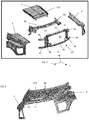
- the hood of a vehicle can include the central cover 1, a rear beam 30, which can provide additional support, fenders 5, 6 and a front end module 34, as shown in FIG. 3 .
- the front end module 34 can comprise the front beam 10, first side rail 36 and second side rail 38 extending between the front beam 10 and a connecting bar 40 (e.g., that can hingedly attach (such as via hinge 18) to the vehicle) (See FIG. 6 ).
- Protruding from the side rails 36, 38, in a direction opposition central portion 42, can be lower supports 44 and upper supports 46, e.g., for attaching a light such as a headlamp to the vehicle, and for providing further support and structural integrity to the fenders 5, 6.
- the front beam 10 can further include grooves 11, 12 sized and shaped to receive the channels 20, 21 in the central cover 1, such that the central cover 1.
- the hood can further include a rear beam 30, which can be used for additional support and/or to attach the hood to the vehicle.
- FIGS. 5A and 5B are exploded views of the various components of the hood.
- the hood includes fenders 5, 6, and central cover 1.
- Central cover 1 can include a front 51, rear 50, and sides 52, 53.
- the central cover 1 can include hollow reinforcements, such as channels 20, 21 that extend between the front beam and the front end module, optionally, from the front 51 to the rear 50.
- the channels 20, 21 can include a first wall 22, a second wall 23, and a bottom portion 24 which connects the first wall 22 and the second wall 23, to define the channel, shown in FIG. 5B .
- Extending from the first wall 22 can be a flange 26, which extends in a direction opposite a main body 7 of the cover.
- the main body 7 of the cover extends from one channel to another channel.
- the channels 20, 21 can extend across the sides 52, 53 of the central cover 1 from the front edge to the rear edge.
- the central cover 1 can further include an optional opening 111 to allow air to pass through to a cooling system or other internal part of a vehicle.
- a handle portion (not shown) can be included on the rear beam.
- a latch 48 or other mechanism for opening the hood can be located on the rear beam such that when released, the hood can pivot around the hinge on the front end module to an open position.
- fenders 5, 6 are located on the sides 52, 53 of the central cover 1.
- Fenders 5, 6 can be formed integral with central cover 1, or attached thereto.
- the fenders 5, 6 can be mounted onto the vehicle by attaching the fenders 5, 6 to the central cover 1, front end module 34 and rear beam 30.
- the fenders 5, 6 can be attached to the central cover 1 such that they extend over the channels 20, 21, as shown in FIG.s 5A and 5B .
- the fenders 5, 6, can at least extend from the front edge 51, to the rear edge 50, and over the channels.
- the edge of the fenders can contact the central cover 1 in a divot or groove 28 designed to receive the fender edge. More preferably, the fenders 5, 6 cover the entirety of the channels 20, 21 such that the channels are not visible from the top of the hood 101, as shown in FIG. 5A .
- the central cover 1 can be mounted to the front beam and the front end module, which, in turn, can be mounted to the chassis (e.g., to the Body-In-White (BIW)) of a vehicle.
- the central cover 1 or the rear beam 30 can be used to attach the hood 101 to the vehicle (not shown).
- the rear beam 30 can be shaped such that the central cover 1 can sit flush on top of the rear beam 30. If the rear beam is positioned underneath the channels 20, 21 in the central cover 1 (not shown) the rear beam can include corresponding grooves such that the channels can be accepted onto the corresponding channels of the rear beam. Alternatively, the channels 20, 21 can end before the rear beam 30 such they do not extend onto the rear beam 30.
- the central cover 1 can be extend onto and be fixedly attached to flange 49 of the rear beam 30. (See FIG. 3 )
- FIGS. 7A and 7B illustrate a simulation comparing the application of a vertical load to the same location in the central panel in a hood system without reinforcements ( FIG. 7A ) and one with reinforcements ( FIG. 7B).
- FIG. 7A shows an uneven displacement, wherein the displacement at a magnitude of 3.5 extending in an elliptical shape (with its major axis extending in the Y direction and the major axis extending in the Z direction) across the central cover.
- the distribution of the load is across less than 70% of the central cover.
- the distribution of load is substantially more uniform across the central panel, with the displacement being circular down to displacements of 3.5, and then generally distributed across greater than or equal to 75% (preferably greater than or equal to 85%) of the central cover.
Description
- This disclosure relates to a structural component of a vehicle, such as a hood system, in particular a plastic hood system.
- Hood systems (also referred to herein as "hood") are large component members of a vehicle body that rotate around a hinge when they open or close. Hoods allow access to engine components in the front of a vehicle, such as a truck. To ensure sufficient strength and stiffness at potentially raised temperatures typically metal or thermoset materials are used to manufacture the hood. Patent publications
WO2016/098024 ,EP0846612 ,US2008/272518 , andUS2005/211484 disclose hood systems for vehicles according to the state of the art. - Because the weight of a vehicle body has an impact on the fuel consumption of the vehicle, attempts have been made to produce hoods from lower density materials, such as polymeric materials, in an effort to reduce the overall weight of the vehicle. The use of polymeric, e.g. thermoplastic, materials reduces the overall weight, but might require design modifications in order to meet the needed structural integrity to accommodate loads placed on the hood, such as the aerodynamic loads while driving or the opening and closing the hood repeatedly. There remains a need for a design that allows the use of plastic for a vehicle hood, while still meeting the different stiffness requirements of the hood.
- Attempts to increase the panel stiffness and torsional rigidity when using plastic materials, include increasing the thickness of components of the hood. The use of reinforcements, such as ribs, can affect the ability to efficiently run wires, cables, or the like on the surface of the component. In addition, ribs and other reinforcements negatively impact the aesthetic quality of the component because such features can leave visible imperfections on the components, thus requiring an aesthetic layer (or panel) to provide a finished appearance; again increasing weight and cost.
- Accordingly, a need exists for a light-weight hood with high torsional and bending stiffness without diminishing the functional and/or aesthetic quality of the component.
- The following is a brief description of the drawings wherein like elements are numbered alike and which are presented for the purposes of illustrating the exemplary embodiments disclosed herein and not for the purposes of limiting the same.
-
FIG. 1 is a perspective view of the front end of a vehicle including the hood system; -
FIG. 2 is view of a portion of the front end of a vehicle; -
FIG. 3 is a perspective view of the components of a hood system before it is assembled; -
FIG. 4 is a perspective front view of a partially assembled hood; -
FIG. 5A is a partial top view of a central cover with fenders attached; -
FIG. 5B is an expanded end view ofportion 5B fromFIG. 5A ; -
FIG. 6 is a partial bottom view of a hood; -
FIG. 7A is a perspective view of the hood system in a simulation showing displacement under vertical load in the center of a hood system without reinforcements; -
FIG. 7B is a perspective view of the hood system in a simulation showing displacement under vertical load in the center of the hood system with reinforcements. - Disclosed herein is a structural component of a vehicle, such as a hood, that has bending and torsional stiffness, in particular, a thermoplastic vehicle component comprising a central cover that extends from a front end module or grill opening reinforcement (hereinafter referred to as front end module), to a rear beam, wherein the central cover including reinforcement, e.g., to enhance bending and torsional stiffness. The hood disclosed herein has a bending and torsion stiffness that meets safety standards and regulations for the particular vehicle on which it is used.
- A hood is a portion of a front of a vehicle, such as a truck, bus, or the like, that is designed to open to allow access to engine components thereof. For example, a hood can be hingedly rotated (e.g., forward) to provide access to vehicle systems, e.g., cooling systems, oil, wiper fluid, etc. Due to their relative size, hoods can be subjected to high torsion and bending loads, e.g., from opening and closing the hood or from aerodynamic loads or highway driving loads. Due to the structural integrity requirements of a hood, the use of thermoplastic materials is particularly problematic and difficult at raised temperatures, e.g., greater than or equal to 80°C. It was found that a hood comprising a central cover with reinforcements, extending between and eventually connected to the front end module and the rear beam, has the structural integrity, e.g., has torsion and bending stiffness to meet the requirements on panel/skin stiffness. Additionally, the structural integrity is attained without the aforementioned aesthetic deficiencies. For example, the hood disclosed herein can have a bending and torsional stiffness so as to exceed a natural frequency of 15 hertz (Hz) when latched, and 1 Hz in an open configuration (such as 60 degree vertical inclination of the hood). Local deflections due to a 10 kilogram (Kg) load placed on a 6 centimeter (cm) diameter area (known as "oil canning") is less than 0.5 cm. Finally, the hood can be closed, from an open configuration, even if pulled from a corner of the hood.
- The central cover comprises the reinforcement and optionally comprises an opening, such as for air flow. The reinforcement can be a channel that extends longitudinally (e.g., in the "Y" direction as illustrated in
FIGs. 3 and7A ) between the front end module and the rear beam. The reinforcement can extend longitudinally between the front end module and the rear beam, preferably at least extend from the front end module to the rear beam. The reinforcement can alternatively end a distance from the rear beam or from the front end module (when the cover is assembled with the front end module and the rear beam). For example, the channels can end a distance from the front and/or rear edge of the central cover such that a support member can be placed underneath the central cover without contacting the channels. - The reinforcements can be formed integrally with the central cover, i.e., molded as a single component. Alternatively, the reinforcement can be formed separately and attached to the central cover, e.g., with an adhesive. The reinforcements may be hollowshaped reinforcements. When formed integrally with the central cover, the reinforcements can be defined by two walls with an optional connecting portion there between. The reinforcement can protrude out of the bottom of the central cover, and can optionally be open on one side (e.g., the top, such as in a U-like shape). The walls of the reinforcement can be located between and connected to an optional flange of the central cover and the main body of the central cover. For example, the first wall can be oriented non-perpendicular to the flange. The second wall can be located perpendicular to the main body. Optionally, the second wall can be located non-perpendicular to the main body. Desirably, the first wall and the second wall converge toward a bottom portion. Optionally, the bottom portion is a single straight member. Optionally the bottom portion is formed of multiple walls. The bottom portion can be a convex connection from the first wall to the second wall.
- Each channel can be the same or a different size, depending upon the structural integrity needed in the specific location or available space. Desirably, the channels are located adjacent the outer periphery of the central cover. For example, the main body comprises greater than or equal to 70% of the width and length of the cover, with each channel located within 15% of the width from the edge of the side of the cover. In other words, if the cover is 100 centimeters wide, the main body, between the channels would be greater than or equal to 70 cm wide (see the double headed arrow in
FIG. 3 ), preferably greater than or equal to 80 cm wide. The reinforcement or channel can be of constant depth (the walls are constant and equal). Optionally, the walls can have different lengths. The dimensions of the reinforcement or channel can be selected to attain the desired bending stiffness and torsional stiffness. Bending stiffness is increased by increasing the depth ("d") of the reinforcement. The torsional stiffness is increased by increasing the width ("w") of the reinforcement. (SeeFIG. 5B ) The specific depth and size of the reinforcements can be dependent upon the desired structural integrity and the vehicle components included under the central cover. For example, if the cover is 100 cm wide, and the walls have a uniform thickness of 0.4 cm, the reinforcement can be over 2.0 cm deep and over 2.0 cm wide to attain torsional and bending stiffness. - The central cover should be of a size sufficient to have desired bending stiffness, while covering the entirety of the mechanical components in the front end of a vehicle. The thickness of the central plate can be dependent on the desired stiffness and the materials used for the central plate. For example, the central plate can be 3 to 5 millimeters (mm) thick. The size of the
central cover 1 can be dependent upon the size of the vehicle; it can be of a size equal to a portion of the front end of a vehicle not covered by fenders, for example, the central cover can have an area of 1 to 2 square meters (m2), e.g., 1.2 to 1.5 m2. - The use of the reinforcements enables enhanced aesthetics while meeting the stiffness requirements. However, if desired, ribs can be included on the central cover.
- Optionally, the central cover and the reinforcements can be separately manufactured, such that the central cover can be a flat cover and the reinforcements can be attached to one side of the central cover.
- The central cover can extend to, onto, or over the front end module. The front end module can comprise a front beam, and additionally may comprise side rails extending between the front beam and a connecting bar. The front beam, side rails, and connecting bar together can form a frame having a central portion, e.g., a grill opening. Extending from the side rails, away from the central portion and toward the fenders, can be supports (e.g., upper and lower supports). The supports can provide further structural integrity to the fenders, and can support lights (such as headlamps). Optionally, the connecting bar can hingedly attach to the vehicle structure so as to allow the hood to open and close. A fender is a barrier piece that surrounds the wheels of a vehicle to block splashing water or mud. In this application, the fender is a side part of the hood that protects the sides of the mechanical system under the hood.
- The front end module can be a structural member such that it has sufficient strength to allow for repeated opening and closing of the hood without damage or failing. The front beam can be shaped complimentary with the central cover. For example, so that the front beam can accept the central cover, such that the central cover can extend over a portion of the front beam and attach thereto. Optionally, the central cover extend over the front beam such that the front beam can attach to the bottom of the cover, such as with an adhesive.
- The front beam can further include grooves sized and shaped to receive the reinforcement in the central cover, e.g., such that the central cover can be attached to the front beam. Optionally the central cover can be flush with the front beam. The grooves in the front beam can provide rigidity to the reinforcement in the central cover, inhibiting twisting movement and hence providing torsional stiffness to the hood design.
- The supports can extend from the side rails such that they extend over and under an opening in the fender for a light.
- Further structural integrity is provided to the hood by the rear beam, which can also be a structural member. The rear beam can provide stiffness so as to distribute the load across the entire hood. The rear beam extends at least the width of the central cover, and preferably from one fender to the other fender (e.g., extends the width of the vehicle). The rear beam can be fixedly attached to the central cover. For example, the central cover can extend over and be attached to a flange of the rear beam. The rear beam can be hingedly attached to the body of the vehicle. If the reinforcement of the central cover extends over the rear beam, the rear beam will comprise grooves to receive the reinforcement. The rear beam can further include a raintray. The raintray can extend the entire length of the rear beam. The rain tray can be included on the top of the rear beam and can comprise a channel with edges. The edges of the rain tray can run parallel to the windshield, such that the rear edge of the rain tray is flush with the lower edge of the windshield. The raintray can receive water and debris (such as leaves), such that the water and debris are prevented from reaching the engine components of the vehicle. The raintray can be formed integral to the rear beam, i.e. formed in the same mold, or can be manufactured separately from the rear beam and attached to the rear beam during assembly.
- Attached to the rear beam, the front end module, and the central cover are the fenders. They can be attached via an adhesive and/or a mechanical attachment such as a clip, bolt, snap-fit connection, or similar removable attachment. The fenders can be attached to the central cover such that they extend over the reinforcement. Therefore, if the reinforcement is an open channel (e.g., a U-like shaped channel), the fenders can cover the opening in the channel (e.g., the longitudinal opening). The fenders can at least extend from the front edge to the rear edge of the central cover and over the channels. The edge of the fenders can contact the central cover in a divot, or groove, or furrow designed to receive the fender edge. More preferably, the fenders cover the entirety of the channels such that the channels are not visible from the top of the hood.
- The fenders can have an opening for a headlamp. The supports from the front end module can extend behind the fender and above and below the opening. The fenders can integrate additional ribbing at their edges, i.e. around the wheel well and front, to increase the bending stiffness. An additional guard piece can be integrated to the fender to minimize risk of impact from road debris, e.g. gravel, from the wheel well.
- The combination of the structural rear beam, front end module, and the central cover with the reinforcement extending between the front end module and the structural rear beam enables torsional stiffness for the hood, allowing the hood to be made of materials such as thermoplastics. Therefore, the hood (e.g., the central cover, fenders, front end module, and/or rear beam) can comprise polymeric material, such as thermoplastic material. Optionally, the central cover can consist of thermoplastic material. Optionally, the fenders can consist of thermoplastic material. Optionally, the front end module and/or rear beam can consist of thermoplastic material. Possible thermoplastic materials include polybutylene terephthalate (PBT); acrylonitrile-butadiene-styrene (ABS); polycarbonate (LEXAN™ and LEXAN™ EXL resins, commercially available from SABIC Innovative Plastics); polycarbonate/PBT blends; polycarbonate/ABS blends; copolycarbonate-polyesters; acrylicstyrene-acrylonitrile (ASA); acrylonitrile-(ethylene-polypropylene diamine modified)-styrene (AES); phenylene ether resins; blends of polyphenylene ether/polyamide (NORYL GTX™ resins, commercially available from SABIC Innovative Plastics); blends of polycarbonate/polyethylene terephthalate (PET/PBT); polybutylene terephthalate and impact modifier (XENOY™ resins, commercially available from SABIC Innovative Plastics); polyamides; phenylene sulfide resins; polyvinyl chloride PVC; high impact polystyrene (HIPS); low/high density polyethylene (L/HDPE); polypropylene (PP); expanded polypropylene (EPP); and thermoplastic olefins (TPO), as well as combinations comprising at least one of the foregoing.
- The thermoplastic can comprise a filler, e.g., a mineral filler. The filler can be fibers, provided the aesthetics requirements on the component are met. The mineral filler can comprise at least one of talc, mica, wollastonite, and calcium carbonate, preferably, the filler comprises talc. For example, the central cover, and optionally the fenders, can comprise a blend of polyamide and polyphenylene ether polymer with mineral filler that has a tensile stress at break, (5 mm/min) of 55 - 65 MegaPascals (MPa) in accordance with ISO 527 such as NORYL GTX™ resin (e.g., NORYL GTX™ resin 679). For example, the front end module and the rear beam can comprise a blend of polyamide and polyphenylene ether polymer with glass filler that has a tensile stress at break, (5 mm/min) of 100 - 120 MPa in accordance with ISO 527; such as NORYL GTX™ resin (e.g., NORYL GTX™ resin 830).
- Optionally, the rear beam and/or the front end module can comprise metal or a thermoset material. Desirably, the central cover, fenders, the rear beam, and the front end module consist of thermoplastic material. Preferably, at least one of the central cover, fenders, the rear beam, and the front end module is free of metal, more preferably, all of the central cover, fenders, the rear beam, and the front end module are free of metal.
- A more complete understanding of the components, processes, and apparatuses disclosed herein can be obtained by reference to the accompanying drawings.
-
FIGS. 1 and2 illustrate a front end of a vehicle (e.g., a truck, bus, train, etc.) includinghood 101. As shown inFIG. 1 ,hood 101 is located in front of thewindshield 99 and above the engine. As shown inFIG. 2 , thehood 101 can include acentral cover 1 that can be used to cover mechanical components of the vehicle. Thecentral cover 1 can significantly affect the aesthetic appearance of the vehicle because it is the predominantly visible section of the front of the vehicle, as shown inFIG. 2 . - The hood of a vehicle can include the
central cover 1, arear beam 30, which can provide additional support,fenders front end module 34, as shown inFIG. 3 . Thefront end module 34 can comprise thefront beam 10,first side rail 36 andsecond side rail 38 extending between thefront beam 10 and a connecting bar 40 (e.g., that can hingedly attach (such as via hinge 18) to the vehicle) (SeeFIG. 6 ). Protruding from the side rails 36, 38, in a direction oppositioncentral portion 42, can belower supports 44 andupper supports 46, e.g., for attaching a light such as a headlamp to the vehicle, and for providing further support and structural integrity to thefenders front beam 10 can further includegrooves channels central cover 1, such that thecentral cover 1. - As shown in
FIG. 4 , the hood can further include arear beam 30, which can be used for additional support and/or to attach the hood to the vehicle. -
FIGS. 5A and 5B are exploded views of the various components of the hood. As shown inFIG. 5A , the hood includesfenders central cover 1.Central cover 1 can include a front 51, rear 50, and sides 52, 53. Thecentral cover 1 can include hollow reinforcements, such aschannels channels first wall 22, asecond wall 23, and abottom portion 24 which connects thefirst wall 22 and thesecond wall 23, to define the channel, shown inFIG. 5B . Extending from thefirst wall 22 can be aflange 26, which extends in a direction opposite amain body 7 of the cover. Themain body 7 of the cover extends from one channel to another channel. - The
channels sides central cover 1 from the front edge to the rear edge. - The
central cover 1 can further include anoptional opening 111 to allow air to pass through to a cooling system or other internal part of a vehicle. - A handle portion (not shown) can be included on the rear beam. For example, a
latch 48 or other mechanism for opening the hood can be located on the rear beam such that when released, the hood can pivot around the hinge on the front end module to an open position. - As shown in
FIGS. 4 and5A ,fenders sides central cover 1.Fenders central cover 1, or attached thereto. Thefenders fenders central cover 1,front end module 34 andrear beam 30. Thefenders central cover 1 such that they extend over thechannels FIG.s 5A and 5B . Thefenders front edge 51, to therear edge 50, and over the channels. The edge of the fenders can contact thecentral cover 1 in a divot or groove 28 designed to receive the fender edge. More preferably, thefenders channels hood 101, as shown inFIG. 5A . - The
central cover 1 can be mounted to the front beam and the front end module, which, in turn, can be mounted to the chassis (e.g., to the Body-In-White (BIW)) of a vehicle. Thecentral cover 1 or therear beam 30 can be used to attach thehood 101 to the vehicle (not shown). As shown inFIG. 6 , therear beam 30 can be shaped such that thecentral cover 1 can sit flush on top of therear beam 30. If the rear beam is positioned underneath thechannels channels rear beam 30 such they do not extend onto therear beam 30. Thecentral cover 1 can be extend onto and be fixedly attached to flange 49 of therear beam 30. (SeeFIG. 3 ) -
FIGS. 7A and 7B illustrate a simulation comparing the application of a vertical load to the same location in the central panel in a hood system without reinforcements (FIG. 7A ) and one with reinforcements (FIG. 7B). FIG. 7A shows an uneven displacement, wherein the displacement at a magnitude of 3.5 extending in an elliptical shape (with its major axis extending in the Y direction and the major axis extending in the Z direction) across the central cover. The distribution of the load is across less than 70% of the central cover. - In
FIG. 7B the distribution of load is substantially more uniform across the central panel, with the displacement being circular down to displacements of 3.5, and then generally distributed across greater than or equal to 75% (preferably greater than or equal to 85%) of the central cover.
Claims (15)
- A hood (101) for a vehicle, comprising:a front end module (34);a thermoplastic central cover (1); andfenders (5, 6) connected to the front end module and thermoplastic central cover, characterized in that the hood further comprises a rear beam (30); andwherein the thermoplastic central cover extends between the rear beam and the front end module, the thermoplastic central cover comprising reinforcements (20, 21) along sides of the thermoplastic central cover extending between the rear beam and the front end module, the reinforcements protruding away from a top surface of the thermoplastic central cover, with a flange (26) extending from a side of the reinforcement; andwherein each fender extends over a reinforcement and connects to a top surface of the thermoplastic central cover.
- The hood of claim 1, wherein the reinforcements are hollow reinforcements.
- The hood of claim 2, wherein the hollow reinforcements are channels that are open on one side and optionally open on ends of the channels.
- The hood of claim 2 or 3, wherein the hollow reinforcements are formed by a first wall (22) extending away from the flange and a second wall (23) extending away from the top surface, and a bottom portion (24) connecting the first wall and the second wall.
- The hood of Claim 4, wherein the first wall meets the flange at a non-perpendicular angle.
- The hood of any of the preceding claims, wherein the thermoplastic central cover comprises a divot located on a side of the reinforcements opposite the flange for receiving an edge of a fender.
- The hood of any of the preceding claims, wherein the reinforcements extend from the rear beam to the front end module.
- The hood of any of the preceding claims, wherein the thermoplastic central cover is free of ribs.
- The hood of any of the preceding claims, wherein the fenders are made of thermoplastic and are free of ribs.
- The hood of any of the preceding claims, wherein the thermoplastic central cover and the fenders are free of metal.
- The hood of any of the preceding claims, wherein the rear beam and the front end module are free of metal.
- The hood of any of the preceding claims, wherein the thermoplastic central cover is formed from thermoplastic and mineral filler.
- The hood of any of the preceding claims, wherein the rear beam comprises a rain tray.
- The hood of any of the preceding claims, wherein the hood has at least one ofa. a stiffness that exceeds a natural frequency of 15 Hz when latched;b. a stiffness that exceeds 1 Hz in an open configuration of a 60 degree vertical inclination of the hood; andc. a local deflection of less than 0.5 cm due to a 10 kg load placed on a 6 cm diameter area of the hood.
- A vehicle comprising: a structural body, an engine, and the hood (101) of any of the preceding claims.
Priority Applications (7)
| Application Number | Priority Date | Filing Date | Title |
|---|---|---|---|
| EP17163013.0A EP3381771B1 (en) | 2017-03-27 | 2017-03-27 | Integrated vehicle hood |
| US15/925,947 US10471998B2 (en) | 2017-03-27 | 2018-03-20 | Integrated vehicle hood |
| RU2018110415A RU2018110415A (en) | 2017-03-27 | 2018-03-23 | COMBINED VEHICLE HOOD |
| BR102018005988-2A BR102018005988A2 (en) | 2017-03-27 | 2018-03-26 | integrated hood for vehicle |
| CN201810258027.9A CN108657291B (en) | 2017-03-27 | 2018-03-27 | Integrated vehicle engine hood |
| US16/545,418 US10829160B2 (en) | 2017-03-27 | 2019-08-20 | Integrated vehicle hood |
| US16/587,482 US11052952B2 (en) | 2017-03-27 | 2019-09-30 | Integrated vehicle hood |
Applications Claiming Priority (1)
| Application Number | Priority Date | Filing Date | Title |
|---|---|---|---|
| EP17163013.0A EP3381771B1 (en) | 2017-03-27 | 2017-03-27 | Integrated vehicle hood |
Publications (2)
| Publication Number | Publication Date |
|---|---|
| EP3381771A1 EP3381771A1 (en) | 2018-10-03 |
| EP3381771B1 true EP3381771B1 (en) | 2021-03-24 |
Family
ID=58428167
Family Applications (1)
| Application Number | Title | Priority Date | Filing Date |
|---|---|---|---|
| EP17163013.0A Active EP3381771B1 (en) | 2017-03-27 | 2017-03-27 | Integrated vehicle hood |
Country Status (5)
| Country | Link |
|---|---|
| US (3) | US10471998B2 (en) |
| EP (1) | EP3381771B1 (en) |
| CN (1) | CN108657291B (en) |
| BR (1) | BR102018005988A2 (en) |
| RU (1) | RU2018110415A (en) |
Families Citing this family (10)
| Publication number | Priority date | Publication date | Assignee | Title |
|---|---|---|---|---|
| EP3381771B1 (en) * | 2017-03-27 | 2021-03-24 | SABIC Global Technologies B.V. | Integrated vehicle hood |
| USD880384S1 (en) * | 2018-01-12 | 2020-04-07 | Jaguar Land Rover Limited | Vehicle front fender |
| USD879675S1 (en) * | 2018-03-02 | 2020-03-31 | Ford Global Technologies, Llc | Vehicle front upper grille |
| USD885270S1 (en) * | 2018-09-27 | 2020-05-26 | GM Global Technology Operations LLC | Vehicle hood |
| USD956637S1 (en) * | 2019-03-29 | 2022-07-05 | Cnh Industrial America Llc | Hood for a work vehicle |
| CN110001788B (en) * | 2019-04-30 | 2021-04-20 | 北京长城华冠汽车科技股份有限公司 | Front end mounting bracket for vehicle and vehicle with same |
| USD928045S1 (en) * | 2019-06-27 | 2021-08-17 | Jaguar Land Rover Limited | Hood decal for a vehicle |
| CN110789638B (en) * | 2019-09-29 | 2020-11-27 | 浙江合众新能源汽车有限公司 | Car size precision control assembly method based on plastic fender |
| USD939409S1 (en) * | 2020-02-25 | 2021-12-28 | GM Global Technology Operations LLC | Vehicle hood |
| USD958708S1 (en) * | 2020-04-13 | 2022-07-26 | Luffy Zongxian Liu | Engine hood |
Family Cites Families (19)
| Publication number | Priority date | Publication date | Assignee | Title |
|---|---|---|---|---|
| US5096611A (en) | 1989-05-25 | 1992-03-17 | Globe-Union Inc. | Process for the production of battery paste |
| US5054567A (en) * | 1989-06-30 | 1991-10-08 | Navistar International Transportation Corp. | Truck hood reinforcement system |
| GB2319994B (en) * | 1996-12-04 | 2001-05-23 | Massey Ferguson Ltd | Vehicle body panel assembly |
| WO2004048183A1 (en) * | 2002-11-26 | 2004-06-10 | General Motors Corporation | Load-bearing body panel assembly for a motor vehicle |
| US7225542B2 (en) * | 2004-01-23 | 2007-06-05 | General Motors Corporation | Vehicle body compartment lid method of manufacturing |
| US7240753B2 (en) * | 2004-02-27 | 2007-07-10 | Ck Technologies, Llc | Vehicle hood assembly |
| FR2875777B1 (en) * | 2004-09-24 | 2008-08-15 | Renault Sas | MOTOR VEHICLE COVER WITH REINFORCED LINING |
| US7416038B2 (en) * | 2005-02-04 | 2008-08-26 | International Truck Intellectual Property Company, Llc | Tubular hinge bar |
| US8096611B2 (en) * | 2005-02-04 | 2012-01-17 | Toyota Jidosha Kabushiki Kaisha | Vehicle front-part structure |
| US7341298B2 (en) * | 2005-05-06 | 2008-03-11 | Jones Performance Products, Inc. | Fiberglass body with reinforcing member |
| US7815249B2 (en) * | 2006-08-28 | 2010-10-19 | Alcoa Inc. | Lightweight hybrid material truck hood |
| US7789179B2 (en) * | 2007-05-03 | 2010-09-07 | International Truck Intellectual Property Company, Llc | Method of compression molding motor vehicle components and parts made therefrom |
| AU2010354770B2 (en) * | 2010-06-07 | 2015-06-25 | Volvo Group North America, Llc | Improved vehicle bumper |
| DE102012012157A1 (en) * | 2011-11-22 | 2013-05-23 | GM Global Technology Operations LLC (n. d. Gesetzen des Staates Delaware) | Hood for a motor vehicle |
| WO2015052655A1 (en) | 2013-10-07 | 2015-04-16 | Sabic Global Technologies B.V. | Closed section geometry, hollow shape, vehicle components |
| EP3233611B1 (en) * | 2014-12-16 | 2020-07-29 | SABIC Global Technologies B.V. | Polymeric engine hood assembly, vehicle front end module, vehicles comprising the same and methods of making the same |
| KR101713724B1 (en) * | 2015-08-12 | 2017-03-08 | 현대자동차 주식회사 | Front vehicle body structure |
| EP3381771B1 (en) * | 2017-03-27 | 2021-03-24 | SABIC Global Technologies B.V. | Integrated vehicle hood |
| US10782047B2 (en) * | 2018-04-16 | 2020-09-22 | Volvo Truck Corporation | Front grille mounting to a motor vehicle hood assembly |
-
2017
- 2017-03-27 EP EP17163013.0A patent/EP3381771B1/en active Active
-
2018
- 2018-03-20 US US15/925,947 patent/US10471998B2/en active Active
- 2018-03-23 RU RU2018110415A patent/RU2018110415A/en not_active Application Discontinuation
- 2018-03-26 BR BR102018005988-2A patent/BR102018005988A2/en not_active Application Discontinuation
- 2018-03-27 CN CN201810258027.9A patent/CN108657291B/en active Active
-
2019
- 2019-08-20 US US16/545,418 patent/US10829160B2/en active Active
- 2019-09-30 US US16/587,482 patent/US11052952B2/en active Active
Non-Patent Citations (1)
| Title |
|---|
| None * |
Also Published As
| Publication number | Publication date |
|---|---|
| RU2018110415A (en) | 2019-09-24 |
| US11052952B2 (en) | 2021-07-06 |
| US20200023908A1 (en) | 2020-01-23 |
| EP3381771A1 (en) | 2018-10-03 |
| US10829160B2 (en) | 2020-11-10 |
| US20190367096A1 (en) | 2019-12-05 |
| US20180273111A1 (en) | 2018-09-27 |
| CN108657291A (en) | 2018-10-16 |
| CN108657291B (en) | 2022-04-29 |
| US10471998B2 (en) | 2019-11-12 |
| BR102018005988A2 (en) | 2018-12-18 |
Similar Documents
| Publication | Publication Date | Title |
|---|---|---|
| EP3381771B1 (en) | Integrated vehicle hood | |
| CN102781731B (en) | Power-absorbing and Vehicular system | |
| US8348313B2 (en) | Energy absorber for vehicle bumper | |
| JP4733091B2 (en) | Automotive roof frame | |
| EP3126706B1 (en) | Hybrid bumper beams and methods for making and using the same | |
| EP3233611B1 (en) | Polymeric engine hood assembly, vehicle front end module, vehicles comprising the same and methods of making the same | |
| KR20180015729A (en) | Energy absorbing assembly, method of making and use thereof | |
| US7988224B2 (en) | Cowl cover assembly for a motor vehicle | |
| US20050269823A1 (en) | Structural beam incorporating wire reinforcement | |
| US20110133499A1 (en) | Bumper for a motor vehicle | |
| CN106604859A (en) | Rear spoiler of motor vehicle | |
| CN109927795A (en) | Vehicle vehicle beam | |
| US5954389A (en) | Reinforced front part for use in the manufacture of cabins/bodies for vehicles | |
| KR20160105593A (en) | Front bumper integrated stiffner | |
| CA2948107A1 (en) | Composite running board | |
| WO2017203009A1 (en) | Polymer hatch door for a vehicle |
Legal Events
| Date | Code | Title | Description |
|---|---|---|---|
| PUAI | Public reference made under article 153(3) epc to a published international application that has entered the european phase |
Free format text: ORIGINAL CODE: 0009012 |
|
| STAA | Information on the status of an ep patent application or granted ep patent |
Free format text: STATUS: THE APPLICATION HAS BEEN PUBLISHED |
|
| AK | Designated contracting states |
Kind code of ref document: A1 Designated state(s): AL AT BE BG CH CY CZ DE DK EE ES FI FR GB GR HR HU IE IS IT LI LT LU LV MC MK MT NL NO PL PT RO RS SE SI SK SM TR |
|
| AX | Request for extension of the european patent |
Extension state: BA ME |
|
| STAA | Information on the status of an ep patent application or granted ep patent |
Free format text: STATUS: REQUEST FOR EXAMINATION WAS MADE |
|
| 17P | Request for examination filed |
Effective date: 20181012 |
|
| RBV | Designated contracting states (corrected) |
Designated state(s): AL AT BE BG CH CY CZ DE DK EE ES FI FR GB GR HR HU IE IS IT LI LT LU LV MC MK MT NL NO PL PT RO RS SE SI SK SM TR |
|
| GRAP | Despatch of communication of intention to grant a patent |
Free format text: ORIGINAL CODE: EPIDOSNIGR1 |
|
| STAA | Information on the status of an ep patent application or granted ep patent |
Free format text: STATUS: GRANT OF PATENT IS INTENDED |
|
| INTG | Intention to grant announced |
Effective date: 20200722 |
|
| GRAS | Grant fee paid |
Free format text: ORIGINAL CODE: EPIDOSNIGR3 |
|
| GRAA | (expected) grant |
Free format text: ORIGINAL CODE: 0009210 |
|
| STAA | Information on the status of an ep patent application or granted ep patent |
Free format text: STATUS: THE PATENT HAS BEEN GRANTED |
|
| AK | Designated contracting states |
Kind code of ref document: B1 Designated state(s): AL AT BE BG CH CY CZ DE DK EE ES FI FR GB GR HR HU IE IS IT LI LT LU LV MC MK MT NL NO PL PT RO RS SE SI SK SM TR |
|
| REG | Reference to a national code |
Ref country code: GB Ref legal event code: FG4D |
|
| REG | Reference to a national code |
Ref country code: CH Ref legal event code: EP |
|
| REG | Reference to a national code |
Ref country code: IE Ref legal event code: FG4D |
|
| REG | Reference to a national code |
Ref country code: AT Ref legal event code: REF Ref document number: 1374218 Country of ref document: AT Kind code of ref document: T Effective date: 20210415 Ref country code: DE Ref legal event code: R096 Ref document number: 602017035056 Country of ref document: DE |
|
| REG | Reference to a national code |
Ref country code: LT Ref legal event code: MG9D |
|
| PG25 | Lapsed in a contracting state [announced via postgrant information from national office to epo] |
Ref country code: GR Free format text: LAPSE BECAUSE OF FAILURE TO SUBMIT A TRANSLATION OF THE DESCRIPTION OR TO PAY THE FEE WITHIN THE PRESCRIBED TIME-LIMIT Effective date: 20210625 Ref country code: FI Free format text: LAPSE BECAUSE OF FAILURE TO SUBMIT A TRANSLATION OF THE DESCRIPTION OR TO PAY THE FEE WITHIN THE PRESCRIBED TIME-LIMIT Effective date: 20210324 Ref country code: HR Free format text: LAPSE BECAUSE OF FAILURE TO SUBMIT A TRANSLATION OF THE DESCRIPTION OR TO PAY THE FEE WITHIN THE PRESCRIBED TIME-LIMIT Effective date: 20210324 Ref country code: NO Free format text: LAPSE BECAUSE OF FAILURE TO SUBMIT A TRANSLATION OF THE DESCRIPTION OR TO PAY THE FEE WITHIN THE PRESCRIBED TIME-LIMIT Effective date: 20210624 Ref country code: BG Free format text: LAPSE BECAUSE OF FAILURE TO SUBMIT A TRANSLATION OF THE DESCRIPTION OR TO PAY THE FEE WITHIN THE PRESCRIBED TIME-LIMIT Effective date: 20210624 |
|
| PG25 | Lapsed in a contracting state [announced via postgrant information from national office to epo] |
Ref country code: RS Free format text: LAPSE BECAUSE OF FAILURE TO SUBMIT A TRANSLATION OF THE DESCRIPTION OR TO PAY THE FEE WITHIN THE PRESCRIBED TIME-LIMIT Effective date: 20210324 Ref country code: LV Free format text: LAPSE BECAUSE OF FAILURE TO SUBMIT A TRANSLATION OF THE DESCRIPTION OR TO PAY THE FEE WITHIN THE PRESCRIBED TIME-LIMIT Effective date: 20210324 Ref country code: SE Free format text: LAPSE BECAUSE OF FAILURE TO SUBMIT A TRANSLATION OF THE DESCRIPTION OR TO PAY THE FEE WITHIN THE PRESCRIBED TIME-LIMIT Effective date: 20210324 |
|
| REG | Reference to a national code |
Ref country code: NL Ref legal event code: MP Effective date: 20210324 |
|
| REG | Reference to a national code |
Ref country code: AT Ref legal event code: MK05 Ref document number: 1374218 Country of ref document: AT Kind code of ref document: T Effective date: 20210324 |
|
| PG25 | Lapsed in a contracting state [announced via postgrant information from national office to epo] |
Ref country code: NL Free format text: LAPSE BECAUSE OF FAILURE TO SUBMIT A TRANSLATION OF THE DESCRIPTION OR TO PAY THE FEE WITHIN THE PRESCRIBED TIME-LIMIT Effective date: 20210324 |
|
| PG25 | Lapsed in a contracting state [announced via postgrant information from national office to epo] |
Ref country code: SM Free format text: LAPSE BECAUSE OF FAILURE TO SUBMIT A TRANSLATION OF THE DESCRIPTION OR TO PAY THE FEE WITHIN THE PRESCRIBED TIME-LIMIT Effective date: 20210324 Ref country code: AT Free format text: LAPSE BECAUSE OF FAILURE TO SUBMIT A TRANSLATION OF THE DESCRIPTION OR TO PAY THE FEE WITHIN THE PRESCRIBED TIME-LIMIT Effective date: 20210324 Ref country code: EE Free format text: LAPSE BECAUSE OF FAILURE TO SUBMIT A TRANSLATION OF THE DESCRIPTION OR TO PAY THE FEE WITHIN THE PRESCRIBED TIME-LIMIT Effective date: 20210324 Ref country code: CZ Free format text: LAPSE BECAUSE OF FAILURE TO SUBMIT A TRANSLATION OF THE DESCRIPTION OR TO PAY THE FEE WITHIN THE PRESCRIBED TIME-LIMIT Effective date: 20210324 Ref country code: LT Free format text: LAPSE BECAUSE OF FAILURE TO SUBMIT A TRANSLATION OF THE DESCRIPTION OR TO PAY THE FEE WITHIN THE PRESCRIBED TIME-LIMIT Effective date: 20210324 |
|
| REG | Reference to a national code |
Ref country code: CH Ref legal event code: PL |
|
| PG25 | Lapsed in a contracting state [announced via postgrant information from national office to epo] |
Ref country code: SK Free format text: LAPSE BECAUSE OF FAILURE TO SUBMIT A TRANSLATION OF THE DESCRIPTION OR TO PAY THE FEE WITHIN THE PRESCRIBED TIME-LIMIT Effective date: 20210324 Ref country code: RO Free format text: LAPSE BECAUSE OF FAILURE TO SUBMIT A TRANSLATION OF THE DESCRIPTION OR TO PAY THE FEE WITHIN THE PRESCRIBED TIME-LIMIT Effective date: 20210324 Ref country code: PT Free format text: LAPSE BECAUSE OF FAILURE TO SUBMIT A TRANSLATION OF THE DESCRIPTION OR TO PAY THE FEE WITHIN THE PRESCRIBED TIME-LIMIT Effective date: 20210726 Ref country code: PL Free format text: LAPSE BECAUSE OF FAILURE TO SUBMIT A TRANSLATION OF THE DESCRIPTION OR TO PAY THE FEE WITHIN THE PRESCRIBED TIME-LIMIT Effective date: 20210324 Ref country code: IS Free format text: LAPSE BECAUSE OF FAILURE TO SUBMIT A TRANSLATION OF THE DESCRIPTION OR TO PAY THE FEE WITHIN THE PRESCRIBED TIME-LIMIT Effective date: 20210724 |
|
| REG | Reference to a national code |
Ref country code: BE Ref legal event code: MM Effective date: 20210331 |
|
| REG | Reference to a national code |
Ref country code: DE Ref legal event code: R097 Ref document number: 602017035056 Country of ref document: DE |
|
| PG25 | Lapsed in a contracting state [announced via postgrant information from national office to epo] |
Ref country code: DK Free format text: LAPSE BECAUSE OF FAILURE TO SUBMIT A TRANSLATION OF THE DESCRIPTION OR TO PAY THE FEE WITHIN THE PRESCRIBED TIME-LIMIT Effective date: 20210324 Ref country code: AL Free format text: LAPSE BECAUSE OF FAILURE TO SUBMIT A TRANSLATION OF THE DESCRIPTION OR TO PAY THE FEE WITHIN THE PRESCRIBED TIME-LIMIT Effective date: 20210324 Ref country code: CH Free format text: LAPSE BECAUSE OF NON-PAYMENT OF DUE FEES Effective date: 20210331 Ref country code: LI Free format text: LAPSE BECAUSE OF NON-PAYMENT OF DUE FEES Effective date: 20210331 Ref country code: MC Free format text: LAPSE BECAUSE OF FAILURE TO SUBMIT A TRANSLATION OF THE DESCRIPTION OR TO PAY THE FEE WITHIN THE PRESCRIBED TIME-LIMIT Effective date: 20210324 Ref country code: LU Free format text: LAPSE BECAUSE OF NON-PAYMENT OF DUE FEES Effective date: 20210327 Ref country code: ES Free format text: LAPSE BECAUSE OF FAILURE TO SUBMIT A TRANSLATION OF THE DESCRIPTION OR TO PAY THE FEE WITHIN THE PRESCRIBED TIME-LIMIT Effective date: 20210324 Ref country code: IE Free format text: LAPSE BECAUSE OF NON-PAYMENT OF DUE FEES Effective date: 20210327 |
|
| PLBE | No opposition filed within time limit |
Free format text: ORIGINAL CODE: 0009261 |
|
| STAA | Information on the status of an ep patent application or granted ep patent |
Free format text: STATUS: NO OPPOSITION FILED WITHIN TIME LIMIT |
|
| PG25 | Lapsed in a contracting state [announced via postgrant information from national office to epo] |
Ref country code: SI Free format text: LAPSE BECAUSE OF FAILURE TO SUBMIT A TRANSLATION OF THE DESCRIPTION OR TO PAY THE FEE WITHIN THE PRESCRIBED TIME-LIMIT Effective date: 20210324 |
|
| 26N | No opposition filed |
Effective date: 20220104 |
|
| PG25 | Lapsed in a contracting state [announced via postgrant information from national office to epo] |
Ref country code: IS Free format text: LAPSE BECAUSE OF FAILURE TO SUBMIT A TRANSLATION OF THE DESCRIPTION OR TO PAY THE FEE WITHIN THE PRESCRIBED TIME-LIMIT Effective date: 20210724 |
|
| PG25 | Lapsed in a contracting state [announced via postgrant information from national office to epo] |
Ref country code: BE Free format text: LAPSE BECAUSE OF NON-PAYMENT OF DUE FEES Effective date: 20210331 |
|
| PG25 | Lapsed in a contracting state [announced via postgrant information from national office to epo] |
Ref country code: IT Free format text: LAPSE BECAUSE OF FAILURE TO SUBMIT A TRANSLATION OF THE DESCRIPTION OR TO PAY THE FEE WITHIN THE PRESCRIBED TIME-LIMIT Effective date: 20210324 |
|
| PGFP | Annual fee paid to national office [announced via postgrant information from national office to epo] |
Ref country code: FR Payment date: 20230208 Year of fee payment: 7 |
|
| PGFP | Annual fee paid to national office [announced via postgrant information from national office to epo] |
Ref country code: GB Payment date: 20230202 Year of fee payment: 7 Ref country code: DE Payment date: 20230131 Year of fee payment: 7 |
|
| PG25 | Lapsed in a contracting state [announced via postgrant information from national office to epo] |
Ref country code: CY Free format text: LAPSE BECAUSE OF FAILURE TO SUBMIT A TRANSLATION OF THE DESCRIPTION OR TO PAY THE FEE WITHIN THE PRESCRIBED TIME-LIMIT Effective date: 20210324 |
|
| P01 | Opt-out of the competence of the unified patent court (upc) registered |
Effective date: 20230529 |
|
| PG25 | Lapsed in a contracting state [announced via postgrant information from national office to epo] |
Ref country code: HU Free format text: LAPSE BECAUSE OF FAILURE TO SUBMIT A TRANSLATION OF THE DESCRIPTION OR TO PAY THE FEE WITHIN THE PRESCRIBED TIME-LIMIT; INVALID AB INITIO Effective date: 20170327 |