EP3753716B1 - Vorrichtung zum auftragen von klebstoff und verfahren zum auftragen von klebstoff - Google Patents
Vorrichtung zum auftragen von klebstoff und verfahren zum auftragen von klebstoff Download PDFInfo
- Publication number
- EP3753716B1 EP3753716B1 EP19886263.3A EP19886263A EP3753716B1 EP 3753716 B1 EP3753716 B1 EP 3753716B1 EP 19886263 A EP19886263 A EP 19886263A EP 3753716 B1 EP3753716 B1 EP 3753716B1
- Authority
- EP
- European Patent Office
- Prior art keywords
- liquid adhesive
- adhesive
- secondary battery
- adhesion space
- sealing part
- Prior art date
- Legal status (The legal status is an assumption and is not a legal conclusion. Google has not performed a legal analysis and makes no representation as to the accuracy of the status listed.)
- Active
Links
Images





Classifications
-
- B—PERFORMING OPERATIONS; TRANSPORTING
- B29—WORKING OF PLASTICS; WORKING OF SUBSTANCES IN A PLASTIC STATE IN GENERAL
- B29C—SHAPING OR JOINING OF PLASTICS; SHAPING OF MATERIAL IN A PLASTIC STATE, NOT OTHERWISE PROVIDED FOR; AFTER-TREATMENT OF THE SHAPED PRODUCTS, e.g. REPAIRING
- B29C65/00—Joining or sealing of preformed parts, e.g. welding of plastics materials; Apparatus therefor
- B29C65/48—Joining or sealing of preformed parts, e.g. welding of plastics materials; Apparatus therefor using adhesives, i.e. using supplementary joining material; solvent bonding
- B29C65/52—Joining or sealing of preformed parts, e.g. welding of plastics materials; Apparatus therefor using adhesives, i.e. using supplementary joining material; solvent bonding characterised by the way of applying the adhesive
-
- B—PERFORMING OPERATIONS; TRANSPORTING
- B05—SPRAYING OR ATOMISING IN GENERAL; APPLYING FLUENT MATERIALS TO SURFACES, IN GENERAL
- B05C—APPARATUS FOR APPLYING FLUENT MATERIALS TO SURFACES, IN GENERAL
- B05C11/00—Component parts, details or accessories not specifically provided for in groups B05C1/00 - B05C9/00
- B05C11/10—Storage, supply or control of liquid or other fluent material; Recovery of excess liquid or other fluent material
-
- B—PERFORMING OPERATIONS; TRANSPORTING
- B05—SPRAYING OR ATOMISING IN GENERAL; APPLYING FLUENT MATERIALS TO SURFACES, IN GENERAL
- B05C—APPARATUS FOR APPLYING FLUENT MATERIALS TO SURFACES, IN GENERAL
- B05C13/00—Means for manipulating or holding work, e.g. for separate articles
- B05C13/02—Means for manipulating or holding work, e.g. for separate articles for particular articles
-
- B—PERFORMING OPERATIONS; TRANSPORTING
- B05—SPRAYING OR ATOMISING IN GENERAL; APPLYING FLUENT MATERIALS TO SURFACES, IN GENERAL
- B05C—APPARATUS FOR APPLYING FLUENT MATERIALS TO SURFACES, IN GENERAL
- B05C3/00—Apparatus in which the work is brought into contact with a bulk quantity of liquid or other fluent material
- B05C3/02—Apparatus in which the work is brought into contact with a bulk quantity of liquid or other fluent material the work being immersed in the liquid or other fluent material
- B05C3/09—Apparatus in which the work is brought into contact with a bulk quantity of liquid or other fluent material the work being immersed in the liquid or other fluent material for treating separate articles
-
- B—PERFORMING OPERATIONS; TRANSPORTING
- B05—SPRAYING OR ATOMISING IN GENERAL; APPLYING FLUENT MATERIALS TO SURFACES, IN GENERAL
- B05D—PROCESSES FOR APPLYING FLUENT MATERIALS TO SURFACES, IN GENERAL
- B05D1/00—Processes for applying liquids or other fluent materials
- B05D1/18—Processes for applying liquids or other fluent materials performed by dipping
-
- B—PERFORMING OPERATIONS; TRANSPORTING
- B29—WORKING OF PLASTICS; WORKING OF SUBSTANCES IN A PLASTIC STATE IN GENERAL
- B29C—SHAPING OR JOINING OF PLASTICS; SHAPING OF MATERIAL IN A PLASTIC STATE, NOT OTHERWISE PROVIDED FOR; AFTER-TREATMENT OF THE SHAPED PRODUCTS, e.g. REPAIRING
- B29C35/00—Heating, cooling or curing, e.g. crosslinking or vulcanising; Apparatus therefor
- B29C35/02—Heating or curing, e.g. crosslinking or vulcanizing during moulding, e.g. in a mould
- B29C35/08—Heating or curing, e.g. crosslinking or vulcanizing during moulding, e.g. in a mould by wave energy or particle radiation
-
- B—PERFORMING OPERATIONS; TRANSPORTING
- B29—WORKING OF PLASTICS; WORKING OF SUBSTANCES IN A PLASTIC STATE IN GENERAL
- B29C—SHAPING OR JOINING OF PLASTICS; SHAPING OF MATERIAL IN A PLASTIC STATE, NOT OTHERWISE PROVIDED FOR; AFTER-TREATMENT OF THE SHAPED PRODUCTS, e.g. REPAIRING
- B29C65/00—Joining or sealing of preformed parts, e.g. welding of plastics materials; Apparatus therefor
- B29C65/48—Joining or sealing of preformed parts, e.g. welding of plastics materials; Apparatus therefor using adhesives, i.e. using supplementary joining material; solvent bonding
-
- B—PERFORMING OPERATIONS; TRANSPORTING
- B29—WORKING OF PLASTICS; WORKING OF SUBSTANCES IN A PLASTIC STATE IN GENERAL
- B29C—SHAPING OR JOINING OF PLASTICS; SHAPING OF MATERIAL IN A PLASTIC STATE, NOT OTHERWISE PROVIDED FOR; AFTER-TREATMENT OF THE SHAPED PRODUCTS, e.g. REPAIRING
- B29C65/00—Joining or sealing of preformed parts, e.g. welding of plastics materials; Apparatus therefor
- B29C65/48—Joining or sealing of preformed parts, e.g. welding of plastics materials; Apparatus therefor using adhesives, i.e. using supplementary joining material; solvent bonding
- B29C65/4805—Joining or sealing of preformed parts, e.g. welding of plastics materials; Apparatus therefor using adhesives, i.e. using supplementary joining material; solvent bonding characterised by the type of adhesives
- B29C65/483—Reactive adhesives, e.g. chemically curing adhesives
- B29C65/4845—Radiation curing adhesives, e.g. UV light curing adhesives
-
- B—PERFORMING OPERATIONS; TRANSPORTING
- B32—LAYERED PRODUCTS
- B32B—LAYERED PRODUCTS, i.e. PRODUCTS BUILT-UP OF STRATA OF FLAT OR NON-FLAT, e.g. CELLULAR OR HONEYCOMB, FORM
- B32B37/00—Methods or apparatus for laminating, e.g. by curing or by ultrasonic bonding
- B32B37/0046—Methods or apparatus for laminating, e.g. by curing or by ultrasonic bonding characterised by constructional aspects of the apparatus
-
- C—CHEMISTRY; METALLURGY
- C09—DYES; PAINTS; POLISHES; NATURAL RESINS; ADHESIVES; COMPOSITIONS NOT OTHERWISE PROVIDED FOR; APPLICATIONS OF MATERIALS NOT OTHERWISE PROVIDED FOR
- C09J—ADHESIVES; NON-MECHANICAL ASPECTS OF ADHESIVE PROCESSES IN GENERAL; ADHESIVE PROCESSES NOT PROVIDED FOR ELSEWHERE; USE OF MATERIALS AS ADHESIVES
- C09J175/00—Adhesives based on polyureas or polyurethanes; Adhesives based on derivatives of such polymers
- C09J175/04—Polyurethanes
- C09J175/14—Polyurethanes having carbon-to-carbon unsaturated bonds
-
- H—ELECTRICITY
- H01—ELECTRIC ELEMENTS
- H01M—PROCESSES OR MEANS, e.g. BATTERIES, FOR THE DIRECT CONVERSION OF CHEMICAL ENERGY INTO ELECTRICAL ENERGY
- H01M10/00—Secondary cells; Manufacture thereof
- H01M10/04—Construction or manufacture in general
-
- H—ELECTRICITY
- H01—ELECTRIC ELEMENTS
- H01M—PROCESSES OR MEANS, e.g. BATTERIES, FOR THE DIRECT CONVERSION OF CHEMICAL ENERGY INTO ELECTRICAL ENERGY
- H01M10/00—Secondary cells; Manufacture thereof
- H01M10/04—Construction or manufacture in general
- H01M10/0404—Machines for assembling batteries
-
- B—PERFORMING OPERATIONS; TRANSPORTING
- B29—WORKING OF PLASTICS; WORKING OF SUBSTANCES IN A PLASTIC STATE IN GENERAL
- B29C—SHAPING OR JOINING OF PLASTICS; SHAPING OF MATERIAL IN A PLASTIC STATE, NOT OTHERWISE PROVIDED FOR; AFTER-TREATMENT OF THE SHAPED PRODUCTS, e.g. REPAIRING
- B29C35/00—Heating, cooling or curing, e.g. crosslinking or vulcanising; Apparatus therefor
- B29C35/02—Heating or curing, e.g. crosslinking or vulcanizing during moulding, e.g. in a mould
- B29C35/08—Heating or curing, e.g. crosslinking or vulcanizing during moulding, e.g. in a mould by wave energy or particle radiation
- B29C35/0805—Heating or curing, e.g. crosslinking or vulcanizing during moulding, e.g. in a mould by wave energy or particle radiation using electromagnetic radiation
- B29C2035/0827—Heating or curing, e.g. crosslinking or vulcanizing during moulding, e.g. in a mould by wave energy or particle radiation using electromagnetic radiation using UV radiation
-
- B—PERFORMING OPERATIONS; TRANSPORTING
- B32—LAYERED PRODUCTS
- B32B—LAYERED PRODUCTS, i.e. PRODUCTS BUILT-UP OF STRATA OF FLAT OR NON-FLAT, e.g. CELLULAR OR HONEYCOMB, FORM
- B32B37/00—Methods or apparatus for laminating, e.g. by curing or by ultrasonic bonding
- B32B37/12—Methods or apparatus for laminating, e.g. by curing or by ultrasonic bonding characterised by using adhesives
- B32B2037/1253—Methods or apparatus for laminating, e.g. by curing or by ultrasonic bonding characterised by using adhesives curable adhesive
-
- H—ELECTRICITY
- H01—ELECTRIC ELEMENTS
- H01M—PROCESSES OR MEANS, e.g. BATTERIES, FOR THE DIRECT CONVERSION OF CHEMICAL ENERGY INTO ELECTRICAL ENERGY
- H01M50/00—Constructional details or processes of manufacture of the non-active parts of electrochemical cells other than fuel cells, e.g. hybrid cells
- H01M50/10—Primary casings; Jackets or wrappings
- H01M50/102—Primary casings; Jackets or wrappings characterised by their shape or physical structure
- H01M50/105—Pouches or flexible bags
-
- Y—GENERAL TAGGING OF NEW TECHNOLOGICAL DEVELOPMENTS; GENERAL TAGGING OF CROSS-SECTIONAL TECHNOLOGIES SPANNING OVER SEVERAL SECTIONS OF THE IPC; TECHNICAL SUBJECTS COVERED BY FORMER USPC CROSS-REFERENCE ART COLLECTIONS [XRACs] AND DIGESTS
- Y02—TECHNOLOGIES OR APPLICATIONS FOR MITIGATION OR ADAPTATION AGAINST CLIMATE CHANGE
- Y02E—REDUCTION OF GREENHOUSE GAS [GHG] EMISSIONS, RELATED TO ENERGY GENERATION, TRANSMISSION OR DISTRIBUTION
- Y02E60/00—Enabling technologies; Technologies with a potential or indirect contribution to GHG emissions mitigation
- Y02E60/10—Energy storage using batteries
Definitions
- electrode active material slurry is applied to a positive electrode collector and a negative electrode collector to manufacture a positive electrode and a negative electrode. Then, the electrodes are stacked on both sides of a separator form an electrode assembly. Also, the electrode assembly is accommodated in a battery case, an electrolyte is injected, and then, sealing is performed.
- a double side folding method in which the sealing part is folded twice is performed, or a method in which an insulation tape is attached to the sealing part has been performed.
- this method has a disadvantage in that manufacturing yield is deteriorated, and a time taken to optimize the equipment is long.
- a method for applying a liquid adhesive to a sealing part to cure the liquid adhesive has been developed.
- a portion of a nozzle that applies the liquid adhesive may be blocked to cause a problem that the liquid adhesive is not applied to the sealing parts of some secondary batteries.
- An object to be solved by the present invention is to provide an apparatus and method for applying an adhesive, which are capable of preventing non-coating of a liquid adhesive and improving productivity of a secondary battery.
- the apparatus includes a side part including a support surface being flat and extending up to a lower part; and the lower part disposed below the side part, and including an adhesion space and a passage connected to the adhesion space so that the liquid adhesive intended to be accommodated in the adhesion space can flow to the adhesion space,wherein the adhesion space is recessed downward from a top surface of the lower part.
- the adhesion space may have a width that is gradually narrowed downward.
- an inner wall facing the support surface may include an upper inner wall of which an edge is chamfered or filleted and a lower inner wall that is parallel to the support surface.
- the apparatus may further include a dispenser configured to inject the liquid adhesive into the passage.
- the apparatus may further include an adhesive tank that stores the liquid adhesive to supply the liquid adhesive to the dispenser.
- the passage may be provided in plurality.
- the side part may further include an inclined surface having a specific inclination toward the inside of the side part from a lower end of the support surface.
- a method for applying a liquid adhesive according to an embodiment of the present invention for solving the above object includes: a step of accommodating the liquid adhesive in an adhesion space of an apparatus for applying the liquid adhesive through a passage; a step of positioning the secondary battery upright and inserting a sealing part disposed at one side of the secondary battery into the adhesion space; a step of withdrawing the secondary battery; and a step of irradiating ultraviolet rays to the sealing part coated with the liquid adhesive.
- the liquid adhesive may be injected into the passage by using a dispenser.
- the dispenser may receive the liquid adhesive from an adhesive tank storing the liquid adhesive to inject the liquid adhesive into the passage.
- the secondary battery may have one surface supported by a support surface of the apparatus for applying the adhesive, and the sealing part disposed at the one side of the secondary battery may be inserted into the adhesion space.
- liquid adhesive may be a urethane acrylate-based adhesive.
- the embodiments of the present invention may have at least the following effects.
- the manufacturing yield may be improved, and also, the productivity of the secondary battery may be improved.
- FIG. 1 is an assembled view of a pouch type secondary battery according to an embodiment of the present invention
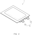
- FIG. 2 is a perspective view of the pouch type secondary battery according to an embodiment of the present invention.
- a process of manufacturing a pouch type secondary battery 1 in a process of manufacturing a pouch type secondary battery 1 according to an embodiment of the present invention, first, slurry in which an electrode active material, a binder, and a plasticizer are mixed with each other is applied to a positive electrode collector and a negative electrode collector to manufacture a positive electrode and a negative electrode. Thereafter, the negative electrode collector and the positive electrode plate are respectively laminated on both sides of a separator to form an electrode assembly 10 having a predetermined shape, and then, the electrode assembly 10 is inserted into a battery case 13, an electrolyte is injected, and sealing is performed.
- the electrode assembly 10 includes an electrode tab 11.
- the electrode tab 11 is connected to each of a positive electrode and a negative electrode of the electrode assembly 10 to protrude to the outside of the electrode assembly 10, thereby providing a path, through which electrons are moved, between the inside and outside of the electrode assembly 10.
- a collector of the electrode assembly 10 is constituted by a portion coated with an electrode active material and a distal end, on which the electrode active material is not applied, i.e., a non-coating portion.
- the electrode tab 11 may be formed by cutting the non-coating portion or by connecting a separate conductive member to the non-coating portion through ultrasonic welding.
- the electrode tabs 11 may protrude from one side of the electrode assembly 10 in the same direction, but the present invention is not limited thereto.
- the electrode tabs 11 may protrude in directions different from each other.
- the electrode lead 12 is connected to the electrode tab 11 through spot welding. Also, a portion of the electrode lead 12 is surrounded by an insulation part.
- the insulation part may be disposed to be limited within a sealing part 134, at which an upper pouch 131 and a lower pouch 132 of the battery case 13 are thermally fused, so that the electrode lead 12 is bonded to the battery case 13. Also, electricity generated from the electrode assembly 10 may be prevented from flowing to the battery case 13 through the electrode lead 12, and the sealing of the battery case 13 may be maintained.
- the insulation part may be made of a nonconductor having non-conductivity, which is not electrically conductive.
- an insulation tape which is easily attached to the electrode lead 12 and has a relatively thin thickness is mainly used as the insulation part, the present invention is not limited thereto.
- various members may be used as the insulation part as long as the members are capable of insulating the electrode lead 12.
- the electrode lead 12 may extend in the same direction or extend in directions different from each other according to the formation positions of the positive electrode tab 111 and the negative electrode tab 112.
- the positive electrode lead 121 and the negative electrode lead 122 may be made of materials different from each other. That is, the positive electrode lead 121 may be made of the same material as the positive electrode plate, i.e., an aluminum (Al) material, and the negative electrode lead 122 may be made of the same material as the negative electrode plate, i.e., a copper (Cu) material or a copper material coated with nickel (Ni). Also, a portion of the electrode lead 12, which protrudes to the outside of the battery case 13, may be provided as a terminal part and electrically connected to an external terminal.
- the battery case 13 may be a pouch made of a flexible material.
- the battery case 13 accommodates the electrode assembly 10 so that a portion of the electrode lead 12, i.e., the terminal part is exposed and then is sealed.
- the battery case 13 includes the upper pouch 131 and the lower pouch 132.
- An accommodation space 1331 in which the electrode assembly 10 is accommodated may be provided in the lower pouch 132, and upper pouch 131 may cover an upper side of the accommodation space 1331 so that the electrode assembly 10 is not separated to the outside of the battery case 13.
- the accommodation space 1331 may also be provided in the upper pouch 131 to accommodate the electrode assembly 10 through an upper side of the upper pouch 131.
- one side of the upper pouch 131 and one side of the lower pouch 132 may be connected to each other.
- the present invention is not limited thereto.
- the upper pouch 131 and the lower pouch may be separately manufactured to be separated from each other.
- the electrode assembly 10 When the electrode lead 12 is connected to the electrode tab 11 of the electrode assembly 10, and the insulation part is provided on a portion of the electrode lead 12, the electrode assembly 10 may be accommodated in the accommodation space 1331 provided in the lower pouch 132, and the upper pouch 131 may cover the upper side of the accommodation space 1331. Also, when the electrolyte is injected, and the sealing part 134 provided on the edge of each of the upper pouch 131 and the lower pouch 132 is sealed, the secondary battery 1 is manufactured as illustrated in FIG. 2 .
- FIG. 3 is a flowchart illustrating a method for applying an adhesive according to an embodiment of the present invention.
- a nozzle since a nozzle is not used, non-coating of a liquid adhesive 3 due to blocking of the nozzle may be prevented. Also, since it is unnecessary to set a line, along which the nozzle moves to apply the liquid adhesive 3, and a coating time, manufacturing yield may be improved, and also, productivity of a secondary battery 1 may be improved.
- the method for applying the adhesive includes: a step of accommodating the liquid adhesive 3 in an adhesion space 221 of an apparatus 2 for applying an adhesive through a passage 222; a step of standing up the secondary battery 1 to insert a sealing part 134 disposed at one side of the secondary battery 1 into the adhesion space 221; a step of withdrawing the secondary battery 1; and a step of irradiating ultraviolet rays to the sealing part 134 coated with the liquid adhesive 3.
- FIG. 4 is a schematic side view of the apparatus 2 for applying the adhesive according to an embodiment of the present invention.
- the apparatus 2 for applying the adhesive includes: a side part 21 including a support surface 211 supporting one surface of the upright secondary battery 1; and a lower part 22 including an adhesion space 221 which accommodates the liquid adhesive 3 and in which the sealing part 134 disposed at the one side of the upright secondary battery 1 is inserted and a passage 222 connected to the adhesion space 221 so that the liquid adhesive 3 flows to the adhesion space 221, wherein the lower part 22 is disposed below the side part 21.
- the side part 21 of the apparatus 2 for applying the adhesive includes the support surface 211.
- the support surface 211 supports one surface of the secondary battery 1 when the secondary battery 1 is positioned upright to be inserted into the adhesion space 221.
- the support surface 211 may be flat. It is preferable that the support surface 211 is parallel to the one surface of the upright secondary battery 1. Thus, the one surface of the secondary battery 1 may be stably supported.
- the lower part 22 of the apparatus 2 for applying the adhesive 3 is disposed below the side part 21 and includes the adhesion space 221 and the passage 222.
- the side part 21 and the lower part 22 of the apparatus 2 for applying the adhesive 3 may be manufactured separately and then assembled, but the present invention is not limited thereto.
- the side part 21 and the lower part 22 may be manufactured integrally, i.e., in various manners without being limited thereto.
- the adhesion space 221 accommodates the liquid adhesive 3 (see FIG. 5 ), and the sealing part 134 disposed at the one side of the secondary battery 1 is inserted into the adhesion space 22.
- the adhesion space 221 may be recessed downward from a top surface of the lower part 22 of the apparatus 2 for applying the adhesive.
- the one surface of the secondary battery 1, which is supported by the support surface 211 may face a left or right side, and the sealing part 134 of the secondary battery may face a lower side.
- the adhesion space 221 is formed in the lower part 22 disposed below the side part 21, the sealing part 134 may be smoothly inserted into the adhesion space 221 while the secondary battery 1 is supported by the support surface 211.
- the adhesion space 221 accommodates the liquid adhesive 3.
- the sealing part 134 of the secondary battery 1 is inserted into the adhesion space 221
- the sealing part 134 of the secondary battery 1 is immersed in the liquid adhesive 3.
- the liquid adhesive 3 is applied to a portion of the sealing part 134 immersed in the liquid adhesive 3.
- an area of the sealing part 134 to be coated with the liquid adhesive 3 may be widened.
- the more an amount of liquid adhesive 3 to be accommodated may decrease.
- the area of the sealing part 134 to be coated with the liquid adhesive 3 may be narrowed.
- the liquid adhesive 3 may be a urethane acrylate (UA)-based adhesive that is cured when ultraviolet (UV) rays are irradiated.
- the urethane acrylate is a compound produced by a UV-curable urethane resin and is a general name of a compound having a urethane bond and an acrylate group together.
- the urethane acrylate is excellent in insulation, flexibility, and abrasion resistance.
- the UV rays 41 see FIG. 8
- the liquid adhesive 3 may be cured to insulate a metal exposed to a cross-section of the sealing part 134.
- the adhesion space 221 is narrower downward. That is, an upper width of the adhesion space 221 may be relatively wider than a lower width. On the other hand, the lower width of the adhesion space 221 may be relatively narrower than the upper width.
- an inner wall referred to a left inner wall in FIG. 4
- the upper inner wall 2211 may have an edge that is chamfered or filleted so that the width of the adhesion space 221 is continuously narrowed downward.
- the sealing part 134 of the secondary battery 1 may be easily inserted.
- the lower inner wall 2212 may be parallel to the support surface 211.
- the sealing part 134 of the secondary battery 1 when the sealing part 134 of the secondary battery 1 is fully inserted into the adhesion space 221, the sealing part 134 of the secondary battery 1 may be stably supported by the lower inner wall 2212.
- a stepped portion may not be formed on the inner wall 2213 (referred to a right inner wall in FIG. 4 ) which faces a side opposite to the support surface 211 in the adhesion space 221.
- the passage 222 is connected to the adhesion space 221 to provide a flow path through which the liquid adhesive 3 flows into the adhesion space 221.
- the present invention is not limited thereto. It is preferable that a plurality of passages 222 are formed so that the liquid adhesive 3 is quickly accommodated in the adhesion space 221.
- the liquid adhesive 3 may be separately provided to be stored in an adhesive tank. Also, the adhesive tank supplies the liquid adhesive 3 stored therein to a dispenser, and the dispenser injects the supplied liquid adhesive 3 to the passage 222. Thus, the liquid adhesive 3 injected into the passage 222 may flow through the passage 222 so as to be accommodated in the adhesion space 221.
- the dispenser may be provided in plurality so that the dispenser corresponding to each of the passages 222 injects the liquid adhesive 3 into the corresponding passage 222.
- the apparatus 2 for applying the adhesive has a height less than that of the secondary battery 1 when the sealing part 134 of the secondary battery 1 is inserted into the adhesion space 221.
- FIG. 5 is a schematic side view illustrating a state in which the liquid adhesive 3 is accommodated in the adhesion space 221 of the apparatus 2 for applying the adhesive according to an embodiment of the present invention.
- the liquid adhesive 3 is accommodated in the adhesion space 221 of the apparatus 2 for applying the adhesive through the passage 222 (S301).
- the adhesive tank storing the liquid adhesive 3 supplies the liquid adhesive 3 to the dispenser
- the liquid adhesive 3 may be injected into the passage 222 by using the dispenser.
- the liquid adhesive 3 may flow through the passage 222 so as to be accommodated in the adhesion space 221.
- FIG. 6 is a schematic side view illustrating a state in which the sealing part 134 of the secondary battery 1 is inserted into the adhesion space 221 of the apparatus 2 for applying the adhesive according to an embodiment of the present invention
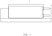
- FIG. 7 is a schematic front view illustrating a state in which the sealing part 134 of the secondary battery 1 is inserted into the adhesion space 221 of the apparatus 2 for applying the adhesive according to an embodiment of the present invention.
- the sealing part 134 formed lengthily in the width direction of the secondary battery 1 is disposed to face the lower side. Also, the sealing part 134 formed lengthily in the width direction is inserted into the adhesion space 221 and immersed in the liquid adhesive 3.
- FIG. 8 is a schematic view illustrating a state in which ultraviolet rays 41 are irradiated to the sealing part 134 of the secondary battery 1 according to an embodiment of the present invention.
- the secondary battery 1 is again withdrawn (S303).
- the liquid adhesive 3 is applied to a portion of the sealing portion 134 that is immersed in the liquid adhesive 3.
- the ultraviolet rays 41 are irradiated to the sealing part 134 to which the liquid adhesive 3 is applied by using an UV lamp 4 (S304).
- the UV lamp 4 is a lamp which irradiates the ultraviolet rays 41 to the outside.
- the ultraviolet rays 41 are an electromagnetic wave of which a wavelength is shorter than that of visible light and thus has a wavelength of approximately 10 nm to approximately 400 nm.
- the ultraviolet rays 41 have a very short wavelength and thus is invisible to the human eye and also have high energy. Thus, ultraviolet rays 41 may be easily used for sterilization and bleaching.
- the liquid adhesive 3 may be a urethane acrylate (UA)-based adhesive that is cured when the ultraviolet rays 41 are irradiated.
- U urethane acrylate
- FIG. 9 is a schematic side view of an apparatus 2a for applying an adhesive according to another embodiment of the present invention.
- the support surface 211 of the side part 21 is parallel to one surface of the secondary battery 1, and the support surface 211 extends up to the lower part 22 of the apparatus 2 for applying the adhesive.
- a portion of the liquid adhesive 3 applied to the sealing part 134 of the secondary battery 1 may drop to contaminate a top surface of the lower part 22 of the apparatus 2 for applying the adhesive.
- the liquid adhesive 3 may remain on the connected edge between the side part 21 and the lower part 22 of the apparatus 2 for applying the adhesive.
- an outer surface of the secondary battery 1 may be contaminated.
- a side part 21a of an apparatus 2a for applying an adhesive has an inclined surface 212a having a specific inclination toward the inside of the side part 21a from a lower end of a support surface 221a.
Landscapes
- Engineering & Computer Science (AREA)
- Chemical & Material Sciences (AREA)
- Chemical Kinetics & Catalysis (AREA)
- General Chemical & Material Sciences (AREA)
- Mechanical Engineering (AREA)
- Manufacturing & Machinery (AREA)
- Electrochemistry (AREA)
- Health & Medical Sciences (AREA)
- Organic Chemistry (AREA)
- Physics & Mathematics (AREA)
- Oral & Maxillofacial Surgery (AREA)
- Thermal Sciences (AREA)
- Toxicology (AREA)
- Sealing Battery Cases Or Jackets (AREA)
- Secondary Cells (AREA)
- Coating Apparatus (AREA)
- Application Of Or Painting With Fluid Materials (AREA)
Claims (12)
- Vorrichtung (2) zum Auftragen eines Flüssigklebstoffs (3), wobei die Vorrichtung umfasst:ein Seitenteil (21) umfassend eine Stützfläche (211), welche flach ist und sich bis zu einem unteren Teil (22) erstreckt; undwobei das untere Teil (22) unterhalb des Seitenteils (21) angeordnet ist und einen Klebstoffraum (221) und eine Passage (222) umfasst, welche mit dem Klebstoffraum (221) verbunden ist, so dass der Flüssigklebstoff, welcher in dem Klebstoffraum (221) aufgenommen werden soll, zu dem Klebstoffraum (221) fließen kann,wobei der Klebstoffraum (221) von einer oberen Fläche des unteren Teils (22) nach unten abgesetzt ist.
- Vorrichtung nach Anspruch 1, wobei der Klebstoffraum (221) eine Weite aufweist, welche sich nach unten hin zunehmend verengt.
- Vorrichtung nach Anspruch 2, wobei in dem Klebstoffraum (221) eine innere Wand, welche der Stützfläche (211) zugewandt ist, eine obere innere Wand (2211), von der eine Kante abgeschrägt oder verrundet ist, und eine untere innere Wand (2212), welche parallel zu der Stützfläche (211) verläuft, umfasst.
- Vorrichtung nach Anspruch 1, ferner umfassend einen Spender, welcher dazu eingerichtet ist, den Flüssigklebstoff (3) in die Passage zu injizieren.
- Vorrichtung nach Anspruch 4, ferner umfassend einen Klebstofftank, welcher den Flüssigklebstoff (3) lagert, um den Flüssigklebstoff dem Spender zuzuführen.
- Vorrichtung nach Anspruch 1, wobei die Passage (222) in einer Vielzahl bereitgestellt ist.
- Vorrichtung nach Anspruch 1, wobei das Seitenteil (21) ferner eine geneigte Fläche (212a) umfasst, welche eine spezifische Neigung in Richtung des Inneren des Seitenteils von einem unteren Ende der Stützfläche (211) aufweist.
- Verfahren zum Auftragen eines Flüssigklebstoffs, wobei das Verfahren umfasst:einen Schritt des Aufnehmens des Flüssigklebstoffs (3) in einem Klebstoffraum (221) einer Vorrichtung zum Auftragen des Klebstoffs durch eine Passage (222);einen Schritt des Positionierens einer Sekundärbatterie in aufrechter Position und des Einführens eines Dichtungsteils, welcher an einer Seite der Sekundärbatterie angeordnet ist, in den Klebstoffraum (221);einen Schritt des Herausziehens der Sekundärbatterie; undeinen Schritt des Bestrahlens des Dichtungsteils, welcher mit dem Flüssigklebstoff (3) beschichtet ist, mit ultravioletten Strahlen.
- Verfahren nach Anspruch 8, wobei in dem Schritt des Injizierens des Flüssigklebstoffs (3) der Flüssigklebstoff in die Passage (222) unter Verwendung eines Spenders injiziert wird.
- Verfahren nach Anspruch 9, wobei der Spender den Flüssigklebstoff (3) aus einem Klebstofftank erhält, welcher den Flüssigklebstoff lagert, um den Flüssigklebstoff in die Passage (222) zu injizieren.
- Verfahren nach Anspruch 8, wobei bei dem Schritt des Injizierens des Dichtungsteils, die Sekundärbatterie eine Fläche aufweist, welche von einer Stützfläche (211) der Vorrichtung zum Auftragen des Klebstoffs gestützt wird, und das Dichtungsteil, welches an der einen Seite der Sekundärbatterie angeordnet ist, in den Klebstoffraum (221) eingeführt wird.
- Verfahren nach Anspruch 8, wobei der Flüssigklebstoff (3) ein Klebstoff auf Urethanacrylatbasis ist.
Applications Claiming Priority (2)
| Application Number | Priority Date | Filing Date | Title |
|---|---|---|---|
| KR1020180143264A KR102363976B1 (ko) | 2018-11-20 | 2018-11-20 | 접착제 도포 장치 및 접착제 도포 방법 |
| PCT/KR2019/010932 WO2020105848A1 (ko) | 2018-11-20 | 2019-08-27 | 접착제 도포 장치 및 접착제 도포 방법 |
Publications (3)
| Publication Number | Publication Date |
|---|---|
| EP3753716A1 EP3753716A1 (de) | 2020-12-23 |
| EP3753716A4 EP3753716A4 (de) | 2021-04-14 |
| EP3753716B1 true EP3753716B1 (de) | 2025-03-19 |
Family
ID=70741855
Family Applications (1)
| Application Number | Title | Priority Date | Filing Date |
|---|---|---|---|
| EP19886263.3A Active EP3753716B1 (de) | 2018-11-20 | 2019-08-27 | Vorrichtung zum auftragen von klebstoff und verfahren zum auftragen von klebstoff |
Country Status (9)
| Country | Link |
|---|---|
| US (1) | US11633923B2 (de) |
| EP (1) | EP3753716B1 (de) |
| JP (1) | JP7107489B2 (de) |
| KR (1) | KR102363976B1 (de) |
| CN (2) | CN211707240U (de) |
| ES (1) | ES3023063T3 (de) |
| HU (1) | HUE071026T2 (de) |
| PL (1) | PL3753716T3 (de) |
| WO (1) | WO2020105848A1 (de) |
Families Citing this family (2)
| Publication number | Priority date | Publication date | Assignee | Title |
|---|---|---|---|---|
| US20240055703A1 (en) * | 2021-11-03 | 2024-02-15 | Lg Energy Solution, Ltd. | Curved Battery Cell |
| US20250205937A1 (en) * | 2022-07-21 | 2025-06-26 | Threebond Co., Ltd. | Gasket molding method, gasket, fuel cell component, fuel cell, fuel cell production method, sealing method, and gasket molding device |
Family Cites Families (26)
| Publication number | Priority date | Publication date | Assignee | Title |
|---|---|---|---|---|
| JPH01242163A (ja) | 1988-03-25 | 1989-09-27 | Jidosha Kiki Co Ltd | 塗膜シェルの外周剪断かしめ部のコーティング方法および装置 |
| US5489409A (en) | 1993-06-25 | 1996-02-06 | Asahi Glass Company, Ltd. | Method of making a window frame and a window panel with a window frame |
| JP3815803B2 (ja) * | 1993-07-02 | 2006-08-30 | 旭硝子株式会社 | 合成樹脂枠体付き窓体の製造方法 |
| CA2207801C (en) * | 1996-06-19 | 2004-03-30 | Hideki Kaido | Nonaqueous electrolyte battery |
| JPH1168136A (ja) * | 1997-08-08 | 1999-03-09 | Sekisui Chem Co Ltd | 太陽電池モジュール、その製造方法及び取付構造 |
| US6165547A (en) * | 1998-11-12 | 2000-12-26 | Ppg Industries Ohio, Inc. | Rolled edge seal for electrooptic device |
| JP3825738B2 (ja) | 2002-10-31 | 2006-09-27 | 三洋電機株式会社 | パック電池とその製造方法 |
| KR100800970B1 (ko) * | 2006-01-18 | 2008-02-11 | 주식회사 엘지화학 | 폴리우레탄으로 가교된 폴리비닐알콜 바인더 및 이를포함하는 리튬 이차전지 |
| CN100401431C (zh) | 2006-08-02 | 2008-07-09 | 中利科技集团股份有限公司 | 热熔胶涂胶装置 |
| JP4931948B2 (ja) * | 2009-02-19 | 2012-05-16 | シャープ株式会社 | 太陽電池モジュール |
| CN102336302A (zh) | 2010-07-27 | 2012-02-01 | 深圳富泰宏精密工业有限公司 | 液体沾取装置及其沾取液体的方法 |
| CN201862534U (zh) * | 2010-11-19 | 2011-06-15 | 哈尔滨光宇电源股份有限公司 | 方形锂离子电池自动点胶机 |
| CN102019251B (zh) | 2010-11-25 | 2012-11-21 | 深圳市豪鹏科技有限公司 | 浸胶机 |
| JP5766132B2 (ja) | 2012-01-30 | 2015-08-19 | 京セラ株式会社 | セルスタック装置および燃料電池装置 |
| CN103567109B (zh) | 2012-07-26 | 2015-12-16 | 耐落螺丝(昆山)有限公司 | 螺丝上胶装置及上胶方法 |
| JP6039394B2 (ja) | 2012-12-13 | 2016-12-07 | 株式会社Jcu | コート槽及びディップコータ |
| CN105098253A (zh) | 2014-05-21 | 2015-11-25 | 东莞新能源科技有限公司 | 一种软包装锂离子电池用双折边装置 |
| CN204018121U (zh) | 2014-06-25 | 2014-12-17 | 昆山圆裕电子科技有限公司 | Fpc批量封胶设备 |
| KR101748645B1 (ko) | 2014-11-17 | 2017-06-19 | 주식회사 엘지화학 | 배터리 모듈 |
| KR101852250B1 (ko) * | 2015-04-02 | 2018-04-26 | 주식회사 엘지화학 | 파우치형 이차전지의 실링 장치 |
| JP6380219B2 (ja) | 2015-04-23 | 2018-08-29 | トヨタ自動車株式会社 | 組電池の製造方法および組電池 |
| CN105826612B (zh) | 2016-04-19 | 2019-04-05 | 宁德新能源科技有限公司 | 一种二次锂电池的封边方法 |
| CN205797689U (zh) | 2016-06-27 | 2016-12-14 | 东莞市卓安精机自动化设备有限公司 | 一种软包锂电芯侧边封胶机 |
| CN206104251U (zh) | 2016-07-09 | 2017-04-19 | 苏州贝克诺斯电子科技股份有限公司 | 一种点胶阀浸泡放置治具 |
| CN206009108U (zh) | 2016-07-25 | 2017-03-15 | 青岛海力威新材料科技股份有限公司 | 一种新型骨架浸涂粘合剂装置 |
| KR20180083123A (ko) | 2017-01-12 | 2018-07-20 | 주식회사 엘지화학 | 파우치형 이차전지의 외부 절연 방법 |
-
2018
- 2018-11-20 KR KR1020180143264A patent/KR102363976B1/ko active Active
-
2019
- 2019-08-27 HU HUE19886263A patent/HUE071026T2/hu unknown
- 2019-08-27 WO PCT/KR2019/010932 patent/WO2020105848A1/ko not_active Ceased
- 2019-08-27 ES ES19886263T patent/ES3023063T3/es active Active
- 2019-08-27 JP JP2021525574A patent/JP7107489B2/ja active Active
- 2019-08-27 PL PL19886263.3T patent/PL3753716T3/pl unknown
- 2019-08-27 US US16/982,243 patent/US11633923B2/en active Active
- 2019-08-27 EP EP19886263.3A patent/EP3753716B1/de active Active
- 2019-11-19 CN CN201922000751.4U patent/CN211707240U/zh active Active
- 2019-11-19 CN CN201911135245.4A patent/CN111195580B/zh active Active
Also Published As
| Publication number | Publication date |
|---|---|
| JP2022507148A (ja) | 2022-01-18 |
| CN211707240U (zh) | 2020-10-20 |
| HUE071026T2 (hu) | 2025-07-28 |
| CN111195580A (zh) | 2020-05-26 |
| CN111195580B (zh) | 2022-03-25 |
| ES3023063T3 (en) | 2025-05-29 |
| EP3753716A1 (de) | 2020-12-23 |
| EP3753716A4 (de) | 2021-04-14 |
| US20210031462A1 (en) | 2021-02-04 |
| KR102363976B1 (ko) | 2022-02-17 |
| JP7107489B2 (ja) | 2022-07-27 |
| WO2020105848A1 (ko) | 2020-05-28 |
| KR20200058753A (ko) | 2020-05-28 |
| PL3753716T3 (pl) | 2025-06-09 |
| US11633923B2 (en) | 2023-04-25 |
Similar Documents
| Publication | Publication Date | Title |
|---|---|---|
| EP3709392B1 (de) | Sekundärbatterie | |
| US20220416374A1 (en) | Apparatus and Method for Bending Electrode Tab | |
| US11108107B2 (en) | Secondary battery and method for manufacturing the same, and pouch for secondary battery and method for manufacturing the same | |
| US12476308B2 (en) | Battery case for secondary battery and pouch type secondary battery | |
| US8227111B2 (en) | Secondary battery having electrolyte sealing plug | |
| EP2557609B1 (de) | Wieder aufladbare Batterie und Herstellungsverfahren dafür | |
| US12017400B2 (en) | Pouch forming apparatus | |
| KR101147175B1 (ko) | 이차전지 | |
| CN110048068A (zh) | 二次电池 | |
| JP2021527936A (ja) | リチウム金属を負極に使用する全固体電池 | |
| KR20210027992A (ko) | 접착제 도포 장치 및 접착제 도포 방법 | |
| EP3753716B1 (de) | Vorrichtung zum auftragen von klebstoff und verfahren zum auftragen von klebstoff | |
| US20230071692A1 (en) | Pouch Type Battery Case and Pouch Type Secondary Battery | |
| KR20210065655A (ko) | 전극조립체 및 그 제조방법 | |
| JP6404577B2 (ja) | 非水電解質二次電池及びその製造方法 | |
| KR101086359B1 (ko) | 이차 전지용 캡 조립체 및 이를 이용한 이차 전지 | |
| KR20140134916A (ko) | 이차 전지용 파우치 제조 방법 및 이차전지용 파우치 | |
| JP6598933B2 (ja) | 非水電解質二次電池及びその製造方法 | |
| EP4043614A1 (de) | Verfahren zum herstellen einer elektrodenleitung und taschenförmige sekundärbatterie | |
| EP4044357A1 (de) | Verfahren zur herstellung einer elektrodenleitung und druckerzeuger | |
| US20250246769A1 (en) | Secondary battery | |
| US11489222B2 (en) | Secondary battery |
Legal Events
| Date | Code | Title | Description |
|---|---|---|---|
| STAA | Information on the status of an ep patent application or granted ep patent |
Free format text: STATUS: THE INTERNATIONAL PUBLICATION HAS BEEN MADE |
|
| PUAI | Public reference made under article 153(3) epc to a published international application that has entered the european phase |
Free format text: ORIGINAL CODE: 0009012 |
|
| STAA | Information on the status of an ep patent application or granted ep patent |
Free format text: STATUS: REQUEST FOR EXAMINATION WAS MADE |
|
| 17P | Request for examination filed |
Effective date: 20200914 |
|
| AK | Designated contracting states |
Kind code of ref document: A1 Designated state(s): AL AT BE BG CH CY CZ DE DK EE ES FI FR GB GR HR HU IE IS IT LI LT LU LV MC MK MT NL NO PL PT RO RS SE SI SK SM TR |
|
| AX | Request for extension of the european patent |
Extension state: BA ME |
|
| A4 | Supplementary search report drawn up and despatched |
Effective date: 20210315 |
|
| RIC1 | Information provided on ipc code assigned before grant |
Ipc: B29C 65/48 20060101AFI20210309BHEP Ipc: C09J 175/14 20060101ALI20210309BHEP Ipc: B29C 35/08 20060101ALI20210309BHEP Ipc: B32B 37/00 20060101ALI20210309BHEP |
|
| RAP3 | Party data changed (applicant data changed or rights of an application transferred) |
Owner name: LG ENERGY SOLUTION, LTD. |
|
| RAP3 | Party data changed (applicant data changed or rights of an application transferred) |
Owner name: LG CHEM, LTD. |
|
| DAV | Request for validation of the european patent (deleted) | ||
| DAX | Request for extension of the european patent (deleted) | ||
| STAA | Information on the status of an ep patent application or granted ep patent |
Free format text: STATUS: EXAMINATION IS IN PROGRESS |
|
| 17Q | First examination report despatched |
Effective date: 20230104 |
|
| RAP1 | Party data changed (applicant data changed or rights of an application transferred) |
Owner name: LG ENERGY SOLUTION, LTD. |
|
| GRAP | Despatch of communication of intention to grant a patent |
Free format text: ORIGINAL CODE: EPIDOSNIGR1 |
|
| STAA | Information on the status of an ep patent application or granted ep patent |
Free format text: STATUS: GRANT OF PATENT IS INTENDED |
|
| RIC1 | Information provided on ipc code assigned before grant |
Ipc: B32B 37/12 20060101ALN20240902BHEP Ipc: H01M 10/04 20060101ALI20240902BHEP Ipc: B05D 1/18 20060101ALI20240902BHEP Ipc: B05C 13/02 20060101ALI20240902BHEP Ipc: B05C 11/10 20060101ALI20240902BHEP Ipc: B05C 3/09 20060101ALI20240902BHEP Ipc: C09J 175/14 20060101ALI20240902BHEP Ipc: B29C 35/08 20060101ALI20240902BHEP Ipc: B32B 37/00 20060101ALI20240902BHEP Ipc: B29C 65/48 20060101AFI20240902BHEP |
|
| INTG | Intention to grant announced |
Effective date: 20240918 |
|
| P01 | Opt-out of the competence of the unified patent court (upc) registered |
Free format text: CASE NUMBER: APP_56672/2024 Effective date: 20241017 |
|
| GRAS | Grant fee paid |
Free format text: ORIGINAL CODE: EPIDOSNIGR3 |
|
| GRAA | (expected) grant |
Free format text: ORIGINAL CODE: 0009210 |
|
| STAA | Information on the status of an ep patent application or granted ep patent |
Free format text: STATUS: THE PATENT HAS BEEN GRANTED |
|
| AK | Designated contracting states |
Kind code of ref document: B1 Designated state(s): AL AT BE BG CH CY CZ DE DK EE ES FI FR GB GR HR HU IE IS IT LI LT LU LV MC MK MT NL NO PL PT RO RS SE SI SK SM TR |
|
| REG | Reference to a national code |
Ref country code: GB Ref legal event code: FG4D |
|
| REG | Reference to a national code |
Ref country code: CH Ref legal event code: EP |
|
| REG | Reference to a national code |
Ref country code: IE Ref legal event code: FG4D |
|
| REG | Reference to a national code |
Ref country code: DE Ref legal event code: R096 Ref document number: 602019067607 Country of ref document: DE |
|
| REG | Reference to a national code |
Ref country code: NL Ref legal event code: FP |
|
| REG | Reference to a national code |
Ref country code: SE Ref legal event code: TRGR |
|
| REG | Reference to a national code |
Ref country code: ES Ref legal event code: FG2A Ref document number: 3023063 Country of ref document: ES Kind code of ref document: T3 Effective date: 20250529 |
|
| PG25 | Lapsed in a contracting state [announced via postgrant information from national office to epo] |
Ref country code: RS Free format text: LAPSE BECAUSE OF FAILURE TO SUBMIT A TRANSLATION OF THE DESCRIPTION OR TO PAY THE FEE WITHIN THE PRESCRIBED TIME-LIMIT Effective date: 20250619 |
|
| PG25 | Lapsed in a contracting state [announced via postgrant information from national office to epo] |
Ref country code: FI Free format text: LAPSE BECAUSE OF FAILURE TO SUBMIT A TRANSLATION OF THE DESCRIPTION OR TO PAY THE FEE WITHIN THE PRESCRIBED TIME-LIMIT Effective date: 20250319 |
|
| REG | Reference to a national code |
Ref country code: LT Ref legal event code: MG9D |
|
| PG25 | Lapsed in a contracting state [announced via postgrant information from national office to epo] |
Ref country code: NO Free format text: LAPSE BECAUSE OF FAILURE TO SUBMIT A TRANSLATION OF THE DESCRIPTION OR TO PAY THE FEE WITHIN THE PRESCRIBED TIME-LIMIT Effective date: 20250619 |
|
| PG25 | Lapsed in a contracting state [announced via postgrant information from national office to epo] |
Ref country code: HR Free format text: LAPSE BECAUSE OF FAILURE TO SUBMIT A TRANSLATION OF THE DESCRIPTION OR TO PAY THE FEE WITHIN THE PRESCRIBED TIME-LIMIT Effective date: 20250319 |
|
| PG25 | Lapsed in a contracting state [announced via postgrant information from national office to epo] |
Ref country code: LV Free format text: LAPSE BECAUSE OF FAILURE TO SUBMIT A TRANSLATION OF THE DESCRIPTION OR TO PAY THE FEE WITHIN THE PRESCRIBED TIME-LIMIT Effective date: 20250319 |
|
| PG25 | Lapsed in a contracting state [announced via postgrant information from national office to epo] |
Ref country code: BG Free format text: LAPSE BECAUSE OF FAILURE TO SUBMIT A TRANSLATION OF THE DESCRIPTION OR TO PAY THE FEE WITHIN THE PRESCRIBED TIME-LIMIT Effective date: 20250319 Ref country code: GR Free format text: LAPSE BECAUSE OF FAILURE TO SUBMIT A TRANSLATION OF THE DESCRIPTION OR TO PAY THE FEE WITHIN THE PRESCRIBED TIME-LIMIT Effective date: 20250620 |
|
| REG | Reference to a national code |
Ref country code: HU Ref legal event code: AG4A Ref document number: E071026 Country of ref document: HU |
|
| REG | Reference to a national code |
Ref country code: AT Ref legal event code: MK05 Ref document number: 1776641 Country of ref document: AT Kind code of ref document: T Effective date: 20250319 |
|
| PGFP | Annual fee paid to national office [announced via postgrant information from national office to epo] |
Ref country code: NL Payment date: 20250722 Year of fee payment: 7 |
|
| PGFP | Annual fee paid to national office [announced via postgrant information from national office to epo] |
Ref country code: HU Payment date: 20250827 Year of fee payment: 7 |
|
| PG25 | Lapsed in a contracting state [announced via postgrant information from national office to epo] |
Ref country code: SM Free format text: LAPSE BECAUSE OF FAILURE TO SUBMIT A TRANSLATION OF THE DESCRIPTION OR TO PAY THE FEE WITHIN THE PRESCRIBED TIME-LIMIT Effective date: 20250319 |
|
| PG25 | Lapsed in a contracting state [announced via postgrant information from national office to epo] |
Ref country code: PT Free format text: LAPSE BECAUSE OF FAILURE TO SUBMIT A TRANSLATION OF THE DESCRIPTION OR TO PAY THE FEE WITHIN THE PRESCRIBED TIME-LIMIT Effective date: 20250721 |
|
| PGFP | Annual fee paid to national office [announced via postgrant information from national office to epo] |
Ref country code: ES Payment date: 20250911 Year of fee payment: 7 |
|
| PGFP | Annual fee paid to national office [announced via postgrant information from national office to epo] |
Ref country code: DE Payment date: 20250721 Year of fee payment: 7 |
|
| PGFP | Annual fee paid to national office [announced via postgrant information from national office to epo] |
Ref country code: TR Payment date: 20250723 Year of fee payment: 7 Ref country code: IT Payment date: 20250722 Year of fee payment: 7 Ref country code: PL Payment date: 20250725 Year of fee payment: 7 |
|
| PGFP | Annual fee paid to national office [announced via postgrant information from national office to epo] |
Ref country code: BE Payment date: 20250722 Year of fee payment: 7 Ref country code: GB Payment date: 20250722 Year of fee payment: 7 |
|
| PG25 | Lapsed in a contracting state [announced via postgrant information from national office to epo] |
Ref country code: AT Free format text: LAPSE BECAUSE OF FAILURE TO SUBMIT A TRANSLATION OF THE DESCRIPTION OR TO PAY THE FEE WITHIN THE PRESCRIBED TIME-LIMIT Effective date: 20250319 |
|
| PGFP | Annual fee paid to national office [announced via postgrant information from national office to epo] |
Ref country code: FR Payment date: 20250725 Year of fee payment: 7 |
|
| PGFP | Annual fee paid to national office [announced via postgrant information from national office to epo] |
Ref country code: SE Payment date: 20250722 Year of fee payment: 7 |
|
| PG25 | Lapsed in a contracting state [announced via postgrant information from national office to epo] |
Ref country code: CZ Free format text: LAPSE BECAUSE OF FAILURE TO SUBMIT A TRANSLATION OF THE DESCRIPTION OR TO PAY THE FEE WITHIN THE PRESCRIBED TIME-LIMIT Effective date: 20250319 Ref country code: EE Free format text: LAPSE BECAUSE OF FAILURE TO SUBMIT A TRANSLATION OF THE DESCRIPTION OR TO PAY THE FEE WITHIN THE PRESCRIBED TIME-LIMIT Effective date: 20250319 |
|
| PG25 | Lapsed in a contracting state [announced via postgrant information from national office to epo] |
Ref country code: RO Free format text: LAPSE BECAUSE OF FAILURE TO SUBMIT A TRANSLATION OF THE DESCRIPTION OR TO PAY THE FEE WITHIN THE PRESCRIBED TIME-LIMIT Effective date: 20250319 |
|
| PG25 | Lapsed in a contracting state [announced via postgrant information from national office to epo] |
Ref country code: SK Free format text: LAPSE BECAUSE OF FAILURE TO SUBMIT A TRANSLATION OF THE DESCRIPTION OR TO PAY THE FEE WITHIN THE PRESCRIBED TIME-LIMIT Effective date: 20250319 |
|
| PG25 | Lapsed in a contracting state [announced via postgrant information from national office to epo] |
Ref country code: IS Free format text: LAPSE BECAUSE OF FAILURE TO SUBMIT A TRANSLATION OF THE DESCRIPTION OR TO PAY THE FEE WITHIN THE PRESCRIBED TIME-LIMIT Effective date: 20250719 |
|
| REG | Reference to a national code |
Ref country code: DE Ref legal event code: R097 Ref document number: 602019067607 Country of ref document: DE |
|
| PG25 | Lapsed in a contracting state [announced via postgrant information from national office to epo] |
Ref country code: DK Free format text: LAPSE BECAUSE OF FAILURE TO SUBMIT A TRANSLATION OF THE DESCRIPTION OR TO PAY THE FEE WITHIN THE PRESCRIBED TIME-LIMIT Effective date: 20250319 |
|
| PLBE | No opposition filed within time limit |
Free format text: ORIGINAL CODE: 0009261 |
|
| STAA | Information on the status of an ep patent application or granted ep patent |
Free format text: STATUS: NO OPPOSITION FILED WITHIN TIME LIMIT |
|
| REG | Reference to a national code |
Ref country code: CH Ref legal event code: L10 Free format text: ST27 STATUS EVENT CODE: U-0-0-L10-L00 (AS PROVIDED BY THE NATIONAL OFFICE) Effective date: 20260128 |
|
| 26N | No opposition filed |
Effective date: 20251222 |
|
| REG | Reference to a national code |
Ref country code: CH Ref legal event code: H13 Free format text: ST27 STATUS EVENT CODE: U-0-0-H10-H13 (AS PROVIDED BY THE NATIONAL OFFICE) Effective date: 20260324 |
|
| PG25 | Lapsed in a contracting state [announced via postgrant information from national office to epo] |
Ref country code: MC Free format text: LAPSE BECAUSE OF FAILURE TO SUBMIT A TRANSLATION OF THE DESCRIPTION OR TO PAY THE FEE WITHIN THE PRESCRIBED TIME-LIMIT Effective date: 20250319 |
|
| PG25 | Lapsed in a contracting state [announced via postgrant information from national office to epo] |
Ref country code: LU Free format text: LAPSE BECAUSE OF NON-PAYMENT OF DUE FEES Effective date: 20250827 |
|
| PG25 | Lapsed in a contracting state [announced via postgrant information from national office to epo] |
Ref country code: CH Free format text: LAPSE BECAUSE OF NON-PAYMENT OF DUE FEES Effective date: 20250831 |