EP3753039B1 - Verfahren und vorrichtung zum magnetronsputtern - Google Patents
Verfahren und vorrichtung zum magnetronsputtern Download PDFInfo
- Publication number
- EP3753039B1 EP3753039B1 EP18719796.7A EP18719796A EP3753039B1 EP 3753039 B1 EP3753039 B1 EP 3753039B1 EP 18719796 A EP18719796 A EP 18719796A EP 3753039 B1 EP3753039 B1 EP 3753039B1
- Authority
- EP
- European Patent Office
- Prior art keywords
- sputter
- substrate
- magnetic field
- pole surface
- target
- Prior art date
- Legal status (The legal status is an assumption and is not a legal conclusion. Google has not performed a legal analysis and makes no representation as to the accuracy of the status listed.)
- Active
Links
Images





Classifications
-
- H—ELECTRICITY
- H01—ELECTRIC ELEMENTS
- H01J—ELECTRIC DISCHARGE TUBES OR DISCHARGE LAMPS
- H01J37/00—Discharge tubes with provision for introducing objects or material to be exposed to the discharge, e.g. for the purpose of examination or processing thereof
- H01J37/32—Gas-filled discharge tubes
- H01J37/34—Gas-filled discharge tubes operating with cathodic sputtering
- H01J37/3402—Gas-filled discharge tubes operating with cathodic sputtering using supplementary magnetic fields
- H01J37/3405—Magnetron sputtering
- H01J37/3408—Planar magnetron sputtering
-
- H—ELECTRICITY
- H01—ELECTRIC ELEMENTS
- H01J—ELECTRIC DISCHARGE TUBES OR DISCHARGE LAMPS
- H01J37/00—Discharge tubes with provision for introducing objects or material to be exposed to the discharge, e.g. for the purpose of examination or processing thereof
- H01J37/32—Gas-filled discharge tubes
- H01J37/34—Gas-filled discharge tubes operating with cathodic sputtering
- H01J37/3411—Constructional aspects of the reactor
- H01J37/345—Magnet arrangements in particular for cathodic sputtering apparatus
- H01J37/3452—Magnet distribution
-
- C—CHEMISTRY; METALLURGY
- C23—COATING METALLIC MATERIAL; COATING MATERIAL WITH METALLIC MATERIAL; CHEMICAL SURFACE TREATMENT; DIFFUSION TREATMENT OF METALLIC MATERIAL; COATING BY VACUUM EVAPORATION, BY SPUTTERING, BY ION IMPLANTATION OR BY CHEMICAL VAPOUR DEPOSITION, IN GENERAL; INHIBITING CORROSION OF METALLIC MATERIAL OR INCRUSTATION IN GENERAL
- C23C—COATING METALLIC MATERIAL; COATING MATERIAL WITH METALLIC MATERIAL; SURFACE TREATMENT OF METALLIC MATERIAL BY DIFFUSION INTO THE SURFACE, BY CHEMICAL CONVERSION OR SUBSTITUTION; COATING BY VACUUM EVAPORATION, BY SPUTTERING, BY ION IMPLANTATION OR BY CHEMICAL VAPOUR DEPOSITION, IN GENERAL
- C23C14/00—Coating by vacuum evaporation, by sputtering or by ion implantation of the coating forming material
- C23C14/22—Coating by vacuum evaporation, by sputtering or by ion implantation of the coating forming material characterised by the process of coating
- C23C14/34—Sputtering
- C23C14/35—Sputtering by application of a magnetic field, e.g. magnetron sputtering
-
- H—ELECTRICITY
- H01—ELECTRIC ELEMENTS
- H01J—ELECTRIC DISCHARGE TUBES OR DISCHARGE LAMPS
- H01J37/00—Discharge tubes with provision for introducing objects or material to be exposed to the discharge, e.g. for the purpose of examination or processing thereof
- H01J37/32—Gas-filled discharge tubes
- H01J37/32431—Constructional details of the reactor
- H01J37/3266—Magnetic control means
-
- H—ELECTRICITY
- H01—ELECTRIC ELEMENTS
- H01J—ELECTRIC DISCHARGE TUBES OR DISCHARGE LAMPS
- H01J37/00—Discharge tubes with provision for introducing objects or material to be exposed to the discharge, e.g. for the purpose of examination or processing thereof
- H01J37/32—Gas-filled discharge tubes
- H01J37/34—Gas-filled discharge tubes operating with cathodic sputtering
- H01J37/3411—Constructional aspects of the reactor
- H01J37/345—Magnet arrangements in particular for cathodic sputtering apparatus
Definitions
- the present invention is directed to magnetron sputtering and thereby to control the direction of magnetic anisotropy in a ferromagnetic layer to be unidirectional.
- the magnetron magnetic field looping along the sputter surface of a target establishes a loop of increased plasma density due to the so-called electron trapping effect.
- This effect is caused by the components of the magnetron magnetic field parallel to the sputter surface and the electric field perpendicular to the sputter surface.
- the erosion profile on the target becomes a loop according to the loop of the magnetron magnetic field.
- the resultant localized erosion profile leads to a poor exploitation of the target and to an angular spacial distribution of sputtered -off target material which varies in time e.g. due to the increasing depth of the erosion profile.
- the EP 1193729 teaches tailoring the magnetron magnetic field of a magnetron sputter device by laterally staggered magnets along the periphery and backside of a target and superposition of their magnetic fields along the sputtering surface of the target, to achieve higher target exploitation.
- US 2007/205096 and the GB 2078787 teach magnet arrangements of magnetron sputtering devices, generating and tailoring different magnetron magnetic field distributions along the sputter surface of the respective targets.
- an electron emitter and an electron collector are provided along opposite lateral sides of a target and a magnetic field is applied traverse to the path from electron emitter to electron collector along the surface of the target.
- Falub Claudiu Valentin "Innovating the soft magnetic for tomorrow's RF passive devices", Evatec Layers, no. 3,14 November 2017 (2017-11-14), XP055895626, DOI:10.13140/RG.2.2.13938,40648 teaches to apply sputter modules, depositing, in combination, multilayers of different ferromagnetic materials on one side of substrates and to apply at the opposed sides of the substrates aligning magnetic field systems.
- the in-plane magnetic anisotropy in the multilayered thin films during sputtering is introduced making use of an aligning magnetic field.
- Innovative soft magnetic multilayers with enhanced in-plane anisotropy and ferromagnetic resonance frequency for integrated RF passive devices AIP ADVANCES, AMERICAN INSTITUTE OF PHYSICS, 2 HUNTINGTON QUADRANGLE, MELVILLE, NY 11747, vol.8, no.4, 23 October 2017 (2017-10-23), XP012223359, DOI: 10.1063/1.4993688 teaches to apply sputter modules, depositing, in combination, multilayers comprising different ferromagnetic material layers on one side of substrates and to apply at the opposed sides of the substrates aligning magnetic field systems.
- the in-plane magnetic anisotropy in the multilayered thin films during sputtering is introduced by a linear magnetic field parallel to the wafer plane, which is designed such that the magnetic field of the magnetron located behind the opposite target is not perturbed.
- a sputtering apparatus comprising:
- the apparatus as taught in a simplified cross-sectional representation by the addressed document comprises:
- the erosion profile loop on the target is enlarged leading to an improved target material exploitation and to the angular distribution of sputtered- off target material varying less in time. This may be achieved without moving a magnetic dipole arrangement relative to the target.
- the superposition as addressed leads to an increased strength of the magnetic field in the reaction space over the magnetron magnetic field strength, resulting in an increased plasma density and thus in an increased sputter rate.
- the methods according to the invention comprise generating the resultant magnetic field along a predominant surface area of the sputter surface.
- the at least one second outer pole surface is provided outside the first outer pole surface, seen in the direction towards the sputter surface, i.e. in top view on the target.
- the at least one second inner pole surface is provided as a part of the sputter surface.
- the at least one second inner pole surface is provided distant from and opposite said sputter surface.
- the at least one second inner pole surface is provided opposite the sputter surface with respect to the substrate e.g. behind the substrate.
- providing the at least one second outer pole surface, seen parallel to the target plane, i.e. in a lateral view, is performed in at least one of the following positions:
- a substrate is not plane and thus a distance to such substrate may possibly not be clearly defined, instead, such distance is defined with respect to a substrate plane, along which such substrate is held by a respective substrate holder.
- the material of the target is selected to be a ferromagnetic material and the direction of magnetic anisotropy in the layer sputter- deposited on the substrate and along at least a predominant part of that surface of the substrate to be sputter coated, is controlled by the resultant magnetic field to be or to become unidirectional.
- the resultant field is homogeneous along the addressed surface area.
- the magnetic polarity of the first outer pole surface and of the at least one second outer pole surface are selected to be equal and the magnetic polarity of the first inner pole surface and of the at least one second inner pole surface are selected to be equal.
- the at least one second outer pole surface seen parallel to said target plane, i.e. in a lateral view, is provided opposite the sputter surface with respect to the substrate.
- One variant of the methods according to the invention comprises providing the loop with a maximum loop diameter, the at least one second outer pole surface comprising an arrangement of limited extent of at least one second pole surface on one side of the maximum diameter and a further arrangement of limited extent of at least one second pole surface on the other side of the maximum diameter, seen in a direction towards the sputter surface, i.e. in a top view towards the target.
- One variant of the variant as just addressed of the methods according to the invention comprises, seen in a direction towards the sputter surface, providing a first leg of the first outer pole surface extending on one side of the maximum diameter along a first linear- i.e. straight- locus and providing a second leg of the first outer pole surface extending on the other side of the maximum diameter along a second linear - i.e. straight- locus , the one arrangement extending along the first leg and the further arrangement extending along the second leg.
- a part or surface "extending along a linear or straight locus” may be straight per se or may e.g. meander about such locus or be arching about such locus.
- first and second legs extend linearly i.e. are straight legs.
- first and second legs are selected to be parallel to each other.
- the one arrangement and the further arrangement extend along respective linear - i.e. straight- loci seen in a direction towards the sputter surface i.e. in a top view towards the target.
- the one and the further arrangements are selected to extend linearly i.e. are straight.
- the one and the further arrangements extend with respective constant spacing aside the respective legs.
- One variant of the methods according to the invention comprises selecting a part of the vacuum-exposed surface of the vacuum enclosure as the at least one second outer pole surface or selecting the vacuum-exposed surface of a part mounted to the vacuum enclosure.
- One variant of the method according to the invention comprises relatively moving the substrate and the target so that the substrate passes across the target.
- One variant of the just addressed variant of the methods according to the invention comprises providing more than one of the substrates and performing the method according to the invention or according to at least one of the variants thereof subsequently on said more than one substrates.
- One variant of the methods according to the invention comprises performing the methods according to the invention or according to at least one of the variants thereof subsequently more than once upon a substrate.
- One variant of the method according to the invention comprises establishing the magnetron magnetic field and the further magnetic field so, that, seen towards the sputter surface i.e. in a top view towards the target, field- lines of the resulting magnetic field extend parallel to a directional axis, over a predominant part of the sputter surface and moving the substrate relative to the target at a constant angle of substrate orientation with respect the directional axis.
- the substrate is rotated relative to the target around a rotation axis which is remote from the substrate.
- the rotation axis is intersecting the normal on the target plane with an angle between 45° and 0°, both limits included.
- the rotational axis In the variant in which the rotational axis "intersects" the addressed normal at an angle of 0°, the rotational axis is in fact parallel to the addressed normal, i.e. perpendicular to the target plane.
- the rotation axis is intersecting the normal on the target plane with an angle between 45° and 90°, both limits included.
- the rotational axis In the variant in which the rotational axis "intersects" the addressed normal at an angle of 90°, the rotational axis is in fact perpendicular to the addressed normal, i.e. parallel to the target plane.
- the rotation axis intersects normals on the surfaces to be sputter-coated of the substrates at angles between 0° and 45°' both limits included and in one variant at an angle of 0°.
- the rotational axis is parallel to the normals on the surfaces to be sputter-coated of the substrates or to normals on respective substrate- planes defined by respective substrate holders.
- the rotation axis intersects normals on the surfaces to be sputter-coated of the substrates at angles between 45° and 90°, both limits included and in one variant at an angle of 90°.
- the rotational axis is perpendicular to the normals on the surfaces to be sputter-coated of the substrates or to the normals on the respective substrateplanes defined by respective substrate holders.
- One variant of the methods according to the invention comprises generating, nearer to the surface to be sputter coated, the strength of the further magnetic field to be larger than the strength of the magnetron magnetic field, and, more remote from the surface to be sputter coated, the strength of the further magnetic field to be weaker than the strength of the magnetron magnetic field.
- first outer pole surface and commonly also the at least one first inner pole surface are respective parts of the sputtering surface.
- first and the second outer pole surfaces as well as the first and the second inner pole surfaces are at least relative to each other stationary. If they are not absolutely stationary, then they are moved together as one entity.
- the target plane and the substrate plane are parallel planes.
- the addressed method- of the invention or every single variant of the method-invention as addressed may be combined with one or more than one of the variants or of the other variants as addressed, unless being in contradiction.
- the at least one second outer pole surface is located outside the first outer pole surface, seen in direction towards the sputter surface i.e. in a top view towards the target.
- the second outer pole surface is located outside the periphery of a substrate on the substrate holder, seen in the direction towards the sputter surface.
- the second outer pole surface is located outside the periphery of the target, seen in direction towards the sputter surface.
- the magnetron magnet-dipole arrangement and the further magnet- dipole arrangement are tailored so that field lines of a magnetron magnetic field generated by the magnetron magnet-dipole arrangement and field lines of a further magnetic field generated by the further magnet- dipole arrangement are mutually parallel along at least a part of the closed loop and as seen in the direction towards the sputter surface.
- the first outer pole surface is a part of the sputter surface.
- the at least one second inner pole surface is a part of the sputter surface.
- the at least one second inner pole surface is distant from the sputter surface.
- the at least one second inner pole surface is located opposite the sputter surface with respect to the substrate plane e.g. behind the substrate.
- the at least one second outer pole surface, seen parallel to the target plane, i.e. in a lateral view, is in at least one of the following positions:
- the first inner pole surface is a further closed loop, seen in the direction towards the sputter surface.
- the second inner pole surface is within said further closed loop, seen in the direction towards the sputter surface.
- At least parts of the first and of the second inner pole surfaces are overlapping, seen in the direction towards the sputter surface.
- the loop of the first outer pole surface has a maximum loop diameter
- the at least one second outer pole surface comprises an arrangement of limited extent of at least one second pole surface on one side of the maximum diameter and a further arrangement of limited extent of at least one second pole surface on the other side of the maximum diameter, seen in the direction towards the sputter surface.
- One embodiment of the apparatus according to the invention comprises, seen in the direction towards the sputter surface, a first leg of the first outer pole surface extending on one side of the maximum diameter along a first linear locus and a second leg of the first outer pole surface extending on the other side of the maximum diameter along a second linear locus, whereby the one arrangement extends along the first leg and the further arrangement extends along the second leg, still seen in the direction towards the sputter surface.
- the first and second legs are linear, i.e. straight, seen in the direction towards the sputter surface.
- the first and the second legs are parallel to each other, seen in a direction towards said sputter surface.
- the arrangement, as addressed above, and the further arrangement as addressed above extend along respective linear loci, seen in the direction towards the sputter surface.
- the one and the further arrangements extend linearly, i.e. are straight, seen in the direction towards the sputter surface.
- the one and the further arrangements extend with respective constant spacing aside the respective legs, seen in a direction towards said sputter surface.
- a part of the vacuum- exposed surface of the vacuum enclosure is the at least one second outer pole surface or a vacuum exposed surface of a part mounted to the vacuum enclosure is the at least one second outer pole surface.
- One embodiment of the apparatus according to the invention comprises at least one further vacuum treatment apparatus, the substrate holder on one hand and the target holder as well as the at least one further vacuum treatment apparatus on the other hand, are drivingly movable relatively to each other, passing the substrate holder across the sputter surface and passing the substrate holder to or from the at least one further vacuum treatment apparatus.
- One embodiment of the apparatus according to the just addressed embodiment comprises more than one of the addressed substrate holders, movable, in one embodiment commonly movable, relative to the sputter surface and the at least one further vacuum treatment apparatus.
- At least one of the addressed further vacuum treatment apparatus is a sputtering chamber as was addressed and according to the invention or according to at least of the embodiments thereof.
- the magnetron magnet-dipole arrangement and the further magnet- dipole arrangement are constructed so, that field lines of a resultant magnetic field, resulting from superposition of a magnetron magnetic field, generated by the magnetron magnet-dipole arrangement, and of a further magnetic field, generated by the further magnet- dipole arrangement, are parallel and extend in direction of a directional axis over a predominant part of the sputter surface or of the substrate holder, once aligned with the sputter surface, and the relative movement of the at least one substrate holder is controlled in such a manner, that the at least one substrate holder passes the sputter surface at a constant angular orientation with respect to the directional axis.
- the substrate holder is drivingly relatively rotatable around a rotation axis which is remote from the sputter surface.
- the rotation axis intersects normals on the substrate planes at angles between 0° and 45°' both limits included.
- the intersecting angle is 0° and thus the rotation axis is parallel to the addressed normals.
- the rotation axis intersects normals on the substrate planes at angles between 45° and 90°' both limits included. In one embodiment this angle is 90° and thus the rotation axis is perpendicular to the addressed normals.
- the rotation axis is intersecting the normal on the target plane with an angle between 45° and 0°, both limits included.
- the rotational axis In the variant in which the rotational axis "intersects" the addressed normal at an angle of 0°, the rotational axis is in fact parallel to the addressed normal, i.e. perpendicular to the target plane.
- the rotation axis is intersecting the normal on the target plane with an angle between 45° and 90°, both limits included.
- the rotational axis In the variant in which the rotational axis "intersects" the addressed normal at an angle of 90°, the rotational axis is in fact perpendicular to the addressed normal, i.e. parallel to the target plane.
- the magnetron dipole arrangement and the further magnet-dipole arrangement are, at least relative to each other, stationary. If they are moveable, then they are moveable together as a unit.
- the target plane and the substrate plane are parallel planes.
- the addressed apparatus - invention or every single embodiment of the apparatus as addressed may be combined with one or more than one of the embodiments or of the other embodiments as addressed, unless being in contradiction.
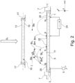
- FIG. 2 shows schematically and heuristically i.e. in a non-scientific manner, the generic approach according to the method and apparatus of the present invention.
- a target 1 mounted to a target holder 3.
- the target 1 is electrically operated as a cathode.
- the target holder 3 defines a target plane 9 as a locus along which the target 1, mounted to the target holder 3, extends.
- the surface of target 1 sputtered off is the sputter surface 11.
- a substrate 13 has a surface 15 to be sputter coated with a material comprising the sputtered off material from the target 1.
- the substrate 13 is mounted to a substrate holder 17 which defines a substrate plane 19, as a locus along which the substrate 13, held by the substrate holder 17, extends.
- the magnetron magnetic field B m emanates from a first outer pole surface 20 shown by thickened lines.
- the first outer pole surface loops along the sputter surface 11 as seen in a direction S1 towards the sputter surface 11, i.e. in a top view towards the target 1.
- the magnetron magnetic field B m impinges on one or more than one first inner pole surfaces 22 also shown by thickened lines in fig.2 .
- the first inner pole surface 22 may be a single pole surface as shown in dash lines.
- a stationary magnetic dipole arrangement 24 is schematically shown only at the right-hand side of the magnetron magnetic field B m -loop for clearness sake.
- the first outer pole surface 20 Seen in the direction S1 i.e. towards the sputter surface 11 or the target plane 9, the first outer pole surface 20 forms a closed loop around the one or more than one first inner pole surfaces 22.
- the first outer pole surface 20 has the magnetic N- polarity, whereas the at least one first inner pole surface 22 has S magnetic polarity. These polarities may be inversed.
- the direction of the magnetron magnetic field B m may be considered in components parallel to the target plane 9, B mx , and in components, B mz , perpendicularly thereto.
- the component B mx govern the electron trap effect of the magnetron and thus the respective plasma density adjacent to the sputter surface 11 and thus the respectively formed race track, i.e. the erosion profile in the sputter surface 11.
- a further magnetic field B a To improve the effect of the magnetron magnetic field B m in the frame of the invention there is generated a further magnetic field B a .
- this further magnetic field B a is generated in the reaction space I so that the resulting magnetic field B r considered at a locus in the reaction space I and resulting from superposition of B m and B a at said locus has larger components B rx parallel to the target plane 9 than the component B mx at that locus.
- the further magnetic field B a must be polarized in a direction equal to the direction of polarization of the magnetron magnetic field B m in the direction x to achieve the addressed improvement.
- B a has a non-vanishing directional component B ax such improvement is achieved and thus along a predominant area of the sputter surface 11.
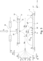
- fig. 3 and 4 show, in a representation in analogy to that of fig. 2 different possibilities to generate the further magnetic field B a .
- the magnetic polarities of all pole surfaces which will be addressed are based on the polarities of the pole surfaces 20 and 22 for the magnetron magnetic field B m according to fig.2 . All these magnetic polarities may be commonly inversed.
- the further magnetic field B a is generated between a second inner pole surface 30 and a second outer pole surface 32.
- the second inner pole surface 30 is located opposite to the sputter surface 11 with respect to the substrate plane 19, e.g. behind the substrate 13.
- the second inner pole surface 30 is further aligned with a central area of the substrate holder 17 as will be discussed later and in any case inside the loop of the first outer pole surface 20 (see fig.2 ) seen in top view -S1- towards the target 1.
- the second inner pole surface 30 may be subdivided in more than one respective pole surface areas.
- the second outer pole surface 32 is located outside the loop of the first outer pole surface 20 (see fig.2 ) and again seen in direction S1. According to fig.3 and seen in a direction y parallel to the target plane 9 and thus in direction of propagation of the magnetron magnetic field loop, as shown by S2, the second outer pole surface or surfaces 32 may be located:
- one or more than one second outer pole surfaces 32 are nevertheless outside the loop of the first outer pole surface 20, seen in direction S1.
- the second outer pole surface 32 may form a loop along the first, looping outer pole surface 20(see fig.2 ): In this case there is provided a single second outer pole surface 32.
- two or more than two distinct second outer pole surfaces 32 may be provided along the loop of the first outer pole surface 20.
- the second outer pole surfaces 32 at the different possible locations (a) to (g) are not shown for the right hand-side part of the further magnetic field B a .
- the positions as shown by (a) to (g) of a single second outer pole surface 32 or of more than one second outer pole surfaces 32 may vary along the loop of the first outer pole surface 20 i.e. there may be provided second outer pole surfaces or a single second outer pole surface at different of the positions (a) to (g).
- pole surfaces 32 and 30 are again shown schematically in fig.3 by thickened lines which is also valid for representation of pole surfaces in following figures.
- FIG. 3 An alternative possibility to tailor the further magnetic field B a is shown in fig. 3 at B a ' in dash lines.
- the second inner pole surface 30' is or are provided as a part of the sputter surface 11.
- B a ' a combination of generating the further magnetic field by B a and by B a ' is also possible.
- the various possibilities (a) to (g) for the second one or more than one second outer pole surfaces 32 are valid irrespective of generating B a and/or B a '.
- the present invention makes use of a further magnetic field B a , B a ', additionally to a magnetron magnetic field B m , which latter, per se, is commonly known.
- such additional magnetic dipole arrangement is located outside the wall 2 of the vacuum enclosure 4 (see fig.1 ) .
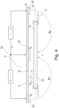
- Fig.4 shows, in a representation in analogy to that of figs 2 or 3 , as an example such a variant and embodiment, thereby generating the further magnetic field in the variant B a , with the second outer pole surface or surfaces 32 in a position according to (a) of fig.3 .
- the magnetic dipole arrangement 34 is provided outside the wall 2 of the vacuum enclosure 4. The target holder, the target and the magnetron magnetic field with respective pole surfaces are not shown in fig.4 .
- the wall 2 of the vacuum enclosure 4 separates sputter processing vacuum from a different gaseous atmosphere U, especially ambient atmosphere.
- the one or more than one second outer pole surfaces 32 reside on the inner, processvacuum exposed surface 2 i of the wall 2.
- the further magnetic dipole arrangement 34 is located outside the vacuum sputter atmosphere as prevailing in the reaction space I, e.g.in ambient atmosphere.
- the generic concept of providing the magnetic dipole arrangement 34 for the further magnetic field B a and/or B a ' separate from the vacuum sputtering atmosphere in the reaction space I may be realized for any variant of generating the further magnetic field B a , B a ' according to fig.3 and the description thereof.
- the example according to fig.4 i.e. having the at least one second outer pole surface 32 as well as the at least one second inner pole surface 30 along the inner surface 2 i of a part of the wall 2 of the vacuum enclosure 4 adjacent to the substrate plane 19, is especially suited if one or more than one substrates 13 with the respective substrate holders 17 are to be moved pass the target 1 as schematically shown by bi-directional or mono-directional arrows M in fig.4 .
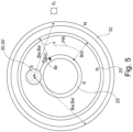
- Fig.5 exemplifies schematically an embodiment of mutual positioning of the pole surfaces, seen in direction S1.
- the looping first outer pole surface 20 is, as an example, forming a circular loop of magnetic polarity N.
- the inner pole surface 22 (see fig.2 ) is provided, with magnetic polarity S.
- the one first inner pole surface 22 forms a circular loop, concentric to the loop of the first outer pole surface 20.
- the second outer pole surface 32 is, in this example looping as well concentrically to and outside the loop of the first outer pole surface 20 thus, in this example, at a constant spacing from the loop of the first outer pole surface 20.
- the at least one second inner pole surface 30 or 30' (see fig.3 ), here just one second inner pole surface, is positioned inside the loop of the first outer pole surface 20 but, here, at a randomly selected position.
- the directions of the magnetron magnetic field B m and of the further magnetic field B a or B a ' are heuristically represented by their magnetic field lines, seen in direction S1.
- the magnetron magnetic field-B m - directions and the directions of the further magnetic field B a ,B a ' intersect at most loci in the reaction space I seen in direction S1 with a respective variable angle ⁇ .
- the resultant magnetic field B r has a direction which is tilted with respect to the propagation direction PR of the magnetron race track.
- the magnetron effect is on one- hand improved by increasing the magnetic field component parallel to the target plane but is on the other hand disturbed by accelerating electrons away from the magnetron propagation direction PR, out of the magnetron electron trap.
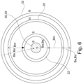
- the directions of the magnetron magnetic field B m and of the further magnetic field B a , B a ' are mutually parallel as seen in direction S1.
- the variant or embodiment of fig.6 differs from that of fig.5 only in that the at least one second inner pole surface 30, 30'is inside the loop of the first inner pole surface 22.
- the first-22- and the second 30,30' inner pole surfaces mutually overlap.
- the magnetic field B r resultant from superposition of the magnetron magnetic field B m and of the further magnetic field B a , B a ' is also present along the surface 15 to be sputter-coated of the substrate 13.
- the methods and apparatus according to the invention is tailored to specifically influence layer deposition on the surface 15 of the substrate 13 to be sputter-coated.
- the influence of the further magnetic field B a , B a ' on the resultant magnetic field B r may be tailored to be more pronounced adjacent to the substrate plane 19 than adjacent to the target plane 9.
- the resultant magnetic field B r resulting from superposition of the magnetron magnetic field B m and of the further magnetic field B a ,B a ', is exploited to establish i.e. to control the direction of magnetic anisotropy in a ferro magnetic layer as sputter deposited to be unidirectional, at least in a predominant part of the layer extent.
- the target 1 mounted or to be mounted on the target holder 3 is of a ferromagnetic material.
- FIG.7 A generic approach of a variant of the methods and embodiments of the apparatus according to the invention is also shown in fig.7 .
- This figure shows mutual positions of the pole surfaces seen in direction S1.
- the shape of the pole surfaces as shown in fig.7 is hardly a shape exploited in praxis, but shall show that, according to specific applications, one is largely free to tailor the respective shapes.
- the looping first outer pole surface 20 may have a loop shape as needed e.g. for a specific shape of the target 1, of the substrate 13.
- the first inner pole surface or surfaces 22, as a loop or as an unitary or more than one unitary pole surfaces, is adapted to the specific shape of the loop of the first outer pole surface 20.
- the loop of the first outer pole surface 20 has a maximum diameter D max .
- the second outer pole surface 32 is realized by two or more than two distinct pole surfaces 32a and 32b extending along respective distances along the maximum diameter D max .
- the shapes and the respective positions of the distinct second outer pole surfaces 32a and 32b is again selected to achieve a desired resultant magnetic field B r from the superposition of magnetron magnetic field B m and of the further magnetic field B a , B a' , which may now be said an "alignment magnetic field".
- the substrate 13 and especially its surface 15 to be sputter coated is located in the rather far field area with respect to the magnetron magnetic field B m and rather in the near field area of the further magnetic field B a , B a' .
- the d coordinate addresses the distance from the sputter surface 11 of target 1 in vertical direction up to the value d o according to the position of the surface 15 to be sputter coated.
- This may be achieved by appropriately selecting, with an eye on figure 3 , the positions of the second outer pole surfaces 32, especially according to one of the variant (a), (b), (c).
- the further magnetic field B a , B a ' improves magnetron sputtering and additionally, provides for unidirectional alignment, parallel to a directional axis, of the magnetic anisotropy along the ferromagnetic material layer which is sputter deposited on surface 15 of the substrate 13.
- the embodiment or variant of positioning the second outer pole surfaces 32 according (a) achieves, on one hand, the desired distribution of field strength, according to figure 8 and, on the other hand, allows to provide the dipole arrangement 34 (see figure 4 ) outside the vacuum enclosure 4 with the wall 2.
- the further magnetic field B a , B a ' should be as parallel as possible to the magnetron magnetic field B m , seen in direction S1.
- the further magnetic field B a , B a ' is exploited as an alignment magnetic field i.e. with the purpose of aligning the direction of magnetic anisotropy in and along the ferromagnetic material layer as sputter-deposited, with respect to a predetermined reference directional- i.e. or orientation-axis over the substrate i.e. over the surface-extent of the layer as being deposited.
- Fig.9 there is heuristically shown the effect of the resultant magnetic field B r on the magnetic anisotropy in the ferromagnetic layer as sputter deposited.
- the magnetic anisotropy is inhomogeneous distributed as schematically shown by easy axis e 1 and hard axis h 1 .
- the magnetic anisotropy in the material of layer 14 is made unidirectional, i.e. the easy axes and, respectively, the hard axes become aligned in a respective unitary direction, e 2d , as shown by e 2 and h 2 .
- the intersecting angle ⁇ of the unidirectionally aligned anisotropy e.g. of the easy axes to the direction r of the applied resultant magnetic field B r is getting very close to 0°.
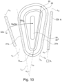
- Fig.10 shows in a representation in analogy to that of fig.7 a further embodiment and variant of the invention.
- the first outer pole face 20 has a first leg 21 a on one side of the maximum diameter D max and a second leg 21 b on the other side of the maximum diameter D max .
- Both legs 21 a and 21 b extend along respective linear loci L a and L b .
- the legs per se need not necessarily be linear i.e. straight, but may be curved forth and back or be bent with respect to the respective linear loci L a , L b .
- the maximum diameter extends along the liner locus L D .
- L a intersects L D at an angle ⁇ a
- L b intersects L D at an angle ⁇ b which is in fig.10 , about 0°.
- the magnetron magnetic field B m appears perpendicular to the diameter D max along a predominant length extent of D max , seen in direction S1.
- the two parts 32 a and 32 b of the second outer pole surface 32 extend along respective linear loci L c and L d .
- These parts per se need not necessarily be linear, but may be curved forth and back or be bent with respect to the respective linear loci L c , L a .
- L c intersects L D at an angle ⁇ c
- L d intersects L D at an angle ⁇ d .
- first and second inner pole surfaces 22, 30, 30' may, generically, be mutually overlapping unitary surfaces or might be realized by a single common pole surface.
- the second outer pole surfaces 32 according to (a) and the second inner pole surfaces as shown at 30 opens the possibility to flexibly position the dipole arrangement 34 for generating the further magnetic field B a remote from the magnetron which comprises the target 1 and the dipole arrangement generating the magnetron magnetic field B m .
- the dipole arrangement 34 may be located on one side of the substrate 13 to be sputter coated, the magnetron on the other side. Especially the dipole arrangement 34 may be positioned outside the reaction space I wherein the substrate 13 is sputter coated.
- the vacuum enclosure 40 has two opposite walls 42 and 43 which limit the reaction space I.
- the reaction space I is operated on sputtering atmosphere conditions.
- the substrate 13 is, in sputtering operation, held on the substrate holder 17.
- the magnetron 48 including the target 1 and the magnetron dipole arrangement (not shown) for generating the magnetron magnetic field B m along the sputter surface of the target 1 is mounted along the wall 42.
- the magnetic dipole arrangement 34 is mounted behind or along the inner surface 43 i which forms the interface between the vacuum processing atmosphere in the reaction space I and non- vacuum processing atmosphere, especially ambient atmosphere U.
- Reference number 32 addresses again the second outer pole surfaces, reference number 30 the second inner pole surfaces according to fig.3 .
- This arrangement is especially suited if the one substrate 13 or more than one substrates 13 with the respective substrate holder 17 is/are drivingly movable as shown with the double arrow M along the reaction space I and across the target 1, be it in a linear movement or in a circular movement as will be addressed later.
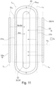
- Fig.13 shows, again schematically and simplified the mutual positioning and the shapes of the pole surfaces realized at the embodiment or variant of the invention as shown in fig.12 .
- the positioning and the shapes of the pole surfaces in fig.13 need no further explanations.
- the movement M of the one or more than one substrates 13 is parallel to the further magnetic field B a as well as to the magnetron magnetic field B m , seen in the direction S1 which accords with the z-coordinate direction, so that this arrangement is perfectly suited to establish in the ferromagnetic material layer, sputter deposited on the substrate or substrates 13, the unidirectional magnetic anisotropy as was addressed over the entire surface of the one or more than one substrates 13.
- Fig.14 shows most schematically substrates 13 according to a variant of the methods or according to an embodiment of the apparatus of the invention, which are drivingly rotatable around a rotational axis A r .
- the normals n on the substrate planes of respective substrate holders intersect the axis A r at an angle ⁇ which is between 45° and 0°, both limits included. If the angle ⁇ is 0° then the normals n are parallel to the axis A r , the rotational axis A r is perpendicular to the respective substrate planes, which are arranged along a plane- locus LP.
- Fig.15 shows most schematically substrates 13 according to a variant of the methods or according to an embodiment of the apparatus of the invention, which are drivingly rotatable around a rotational axis A r .
- the normals n on the substrate planes of respective substrate holders intersect the axis A r at an angle ⁇ which is between 45° and 90°, both limits included. If the angle ⁇ is 90° then the normals n are perpendicular to the axis A r , the rotational axis A r is parallel to the respective substrate planes, which are arranged along a cylinder locus LC.
- the rotational axis A r may especially be perpendicular to the target plane for target 1 whereas in the variant or embodiment of fig.15 the rotational axis may especially be parallel to the target planes of targets 1.
- the vacuum treatment apparatus 45 comprises at least one sputtering and alignment apparatus also called alignment station 50 according to the invention and according to the variant or embodiment of the figs.11 to 13 , possibly also according to the variant or embodiment of fig.10 .
- the vacuum treatment apparatus 45 comprises an outer stationary cylinder 52 with an axis A c and with an inner cylinder-surface 52 i and, coaxially to axis A c , an inner stationary cylinder 54 with an outer surface 54 o .
- the inner surface 52 i and the outer surface 54 o commonly define a cylindric reaction space I pumped by a pumping arrangement 56.
- a substrate holder carrousel 57 is rotatable - ⁇ - around axis A c , controllably driven by a drive 58.
- the substrate holder carrousel 57 holds a multitude of substrates 13 to be vacuum treated.
- the magnetron 48 is e.g. mounted to the outer cylinder 52, whereas the dipole arrangement 34 for generating the alignment magnetic field B a is mounted to the inner cylinder 54, outside the reaction space I. Every area of the substrates 13 passes the sputter and alignment station 50 with a movement direction which is parallel to B a and B m seen in z direction, which accords with the S1- direction.
- the directions of magnetic anisotropy in ferromagnetic layers deposited on the substrates 13 are aligned with respect to one reference directional axis r (see fig.9 ).
- the substrates may be of any shape, e.g. circular disk shaped, rectangular or square. Multiple thin layers of ferromagnetic material may be deposited on the substrates by subsequently passing the substrates 13 through respective sputter and alignment stations 50, possibly depositing intermediate non- ferromagnetic layers, e.g. by sputter-stations 51.
- the targets of the sputter and alignment stations 50 are of a ferromagnetic material. Nevertheless, it is also possible to provide one or the other or all sputter and alignment stations 50 with non-ferromagnetic targets and exploit the inventively applied further magnetic fields merely for improving the magnetron effect. Then these stations 50 become rather improved sputtering stations than sputtering and alignment stations.
- the magnetrons 48 could be mounted to the inner cylinder 54 and the dipole arrangement 34 to or along the outer cylinder 52. This especially if the inner cylinder 54 is hollow and allows easy handling of the magnetrons 48 e.g. for the exchange of the targets 1.
- the vacuum treatment apparatus 45 may comprise one or more than one sputter and alignments stations 50 according to the invention and possibly one or more than one further vacuum treatment stations 51 as of etching stations, sputtering stations, etc.
- the substrates are rotated around axis A c with the normals N o on their extended surfaces pointing in radial direction with respect to axis A c .
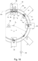
- Fig.16 and 17 show schematically and simplified a further vacuum treatment apparatus 55 according to the invention and performing a sputtering method or substrate manufacturing method according to the invention.
- This variant or embodiment generically accords with the variant or embodiment of fig.14 with the rotational axis A r perpendicular to the target planes.
- substrates 13 are deposited on a disk or ring-shaped substrate carrousel 67 for multiple substrates 13.
- the disk or ring-shaped substrate carrousel 67 is rotatable around an axis A D , controllably driven by a drive 68.
- the vacuum enclosure 60 defines a disk or ring-shaped reaction space I wherein the disk or ring-shaped substrate carousel 67 is rotatable.
- the vacuum enclosure 60 comprises a top wall 70 with an inner surface 70 i , and a bottom wall 72 with an inner surface 72 i , extending perpendicularly to the axis A D .
- Substrates 13 are arranged along the periphery of the substrate holder carousel 67 with their normals N o on their extended surfaces parallel to the axis A D .
- the magnetic dipole arrangement 34 is mounted outside the reaction space I, along or outside the bottom wall 72, whereas the magnetron 48 is mounted to the top wall 70.
- the sputter and alignment station 50 according the invention is mounted in alignment with the moving path of the substrates 13 as rotated around axis A D .
- multiple sputter and alignment stations 50 may be provided so as to deposit on the substrates 13 multiple thin ferromagnetic layers possibly with interposed layers of non-ferromagnetic material as sputter-deposited by sputter-stations 51.
- the substrates 13 may be drivingly rotated- ⁇ 13 - around their central axes A 13 , which also prevails for such case at the embodiment of fig.16 .
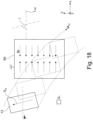
- a substrate 13 is moved pass such a station 50 for aligning the magnetic anisotropy in the ferro-magnetic layer as deposited along an axis r (see fig.9 ) then the substrate should pass the station 50 maintaining a constant directional orientation with respect to the direction of the resulting magnetic field B r of the station 50. This is exemplified in fig.18 .
- the stationary station 50 generates, seen in direction S1, a homogeneous resulting magnetic field B r in one direction, according to a linear locus L 50 .
- a substrate 13 is moved - M 13 -relative to the station 50 whereby the complete extended surface of the substrate passes through the area of field B r .
- V 13 indicates the orientation of the substrate 13 in the x/y plane. At least during a time span, in which the substrate 13 becomes exposed to the magnetic field B r of the station 50, the angle r between the orient a tion V 13 of the substrate 13 and the locus L 50 should be kept constant.
- the movement of the substrates 13 passing in a rotational movement around axis A D the one or more than one stations 50 acting as sputter and alignment stations is additionally to be controlled to fulfil the condition as described in context wit fig.18 .
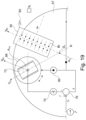
- Fig.19 shows schematically and simplified one possibility of fulfilling the condition as exemplified in fig. 18 at a variant and embodiment of fig.17 .
- the station 50 acting as a sputter and alignment station is rigidly mounted with respect to the vacuum recipient 60, as schematically shown. With respect to a selected angle reference R, the angle ⁇ o of the orientation direction of the resulting magnetic field B r is known.
- a reference orientation direction on the substrate is established and thus known. Such reference orientation may be marked on the substrate 13 as by a flat, but needs not to be physically recognizable on the substrate 13.
- an angle sensor 74 coupled to the rotation axis A 13 of the substrate holder 66 the prevailing angle ⁇ ' between the prevailing orientation direction V 13 of the substrate and the direction V 50 of the magnetic field B r is measured.
- the angle ⁇ ' is controlled to be constant on a selected angle value ⁇ o .
- the prevailing measured angle ⁇ ' is compared at a difference forming unit 76 with the desired angle ⁇ o and the resulting difference ⁇ , the control difference, is led via an appropriate controller (not shown) to the control input of a rotation drive 80 for the substrate holder 66 around axis A 13 , as the adjusting member in the negative feedback control loop.
- the substrate 13 passes the station 50 at a constant, selectable angle ⁇ o with respect to the direction of the magnetic field B r .
Landscapes
- Chemical & Material Sciences (AREA)
- Engineering & Computer Science (AREA)
- Physics & Mathematics (AREA)
- Plasma & Fusion (AREA)
- Analytical Chemistry (AREA)
- Chemical Kinetics & Catalysis (AREA)
- Materials Engineering (AREA)
- Mechanical Engineering (AREA)
- Metallurgy (AREA)
- Organic Chemistry (AREA)
- Physical Vapour Deposition (AREA)
Claims (37)
- Verfahren für Magnetron-Sputter-Abscheidung oder für die Herstellung eines Substrats beschichtet mit einer mittels Magnetron-Sputtern abgeschiedenen Schicht, umfassend:• Bereitstellung eines Zielobjekts (1) aus einem ferromagnetischen Material mit einer Sputter-Oberfläche (11) die sich entlang einer Zielobjekt-Ebene (9) erstreckt, in einem Vakuum-Gehäuse (4,40,60);• Bereitstellung eines Substrates (13) mit einer Oberfläche, die mittels Sputterns (15) zu beschichten ist;• Bereitstellung eines Reaktionsraums (I) zwischen besagter Sputter-Oberfläche (11) und besagter Oberfläche (15) die mittels Sputterns zu beschichten ist;• Erzeugen eines Magnetron-Magnetfeldes (Bm) in besagtem Reaktionsraum (I), dessen magnetische Feldlinien einen zwischen einer ersten äusseren Polfläche (20) besagter Sputter-Oberfläche (11) und einer ersten inneren Polfläche (22) einen Bogen bilden, wobei besagte erste äussere Polfläche (20) eine geschlossene Schleife auf besagter Sputter-Oberfläche (11) um besagte erste innere Polfläche (22) bildet, gesehen in Richtung (S1) gegen besagte Sputter-Oberfläche (11);• Erzeugen eines weiteren Magnetfeldes (Ba) in besagtem Reaktionsraum (I);• Erzeugen eines resultierenden Magnetfeldes (Br) in besagtem Reaktionsraum (I) durch Superposition des besagten Magnetron-Magnetfeldes (Bm) und des besagten weiteren Magnetfeldes (Ba),• Kontrollieren der Richtung der magnetischen Anisotropie in der durch Sputtern abgeschiedenen Schicht auf besagtem Substrat durch besagtes resultierendes Magnetfeld um unidirektional zu werden, entlang mindestens eines überwiegenden Teils besagter Oberfläche besagten Substrates die mittels Sputterns zu beschichten ist,• Erzeugen besagten resultierenden Magnetfeldes entlang eines überwiegenden Oberflächenbereiches der besagten Oberfläche des besagten Substrats, die mittels Sputterns zu beschichten ist,
gekennzeichnet durch• Erzeugen besagten weiteren magnetischen Feldes zwischen mindestens einer zweiten äusseren Polfläche (32) und mindestens einer zweiten inneren Polfläche (30);• Wählen der gleichen magnetischen Polarität besagter ersten äusseren Polfläche und der magnetischen Polarität besagter mindestens einen zweiten äusseren Polfläche und wählen der gleichen magnetischen Polarität besagter ersten inneren Polfläche und der magnetischen Polarität besagter mindestens einen zweiten inneren Polfläche, wobei die Richtungskomponente des besagten resultierenden Magnetfeldes (Br), parallel zur besagten Zielobjekt-Ebene (9), an einem Ort in besagtem Reaktionsraum (I) grösser ist als die Richtungskomponente besagten Magnetron- Magnetfeldes (Bm), parallel zur besagten Zielobjekt-Ebene (9) an besagtem Ort, mindestens in einem überwiegendem Volumenbereich besagten Reaktionsraumes (I). - Verfahren nach Anspruch 1 umfassend Auslegen besagten Magnetron-Magnetfeldes (Bm) und besagten weiteren Magnetfeldes (Ba) in besagtem Reaktionsraum (I), so, dass, betrachtet in die Richtung gegen besagte Sputter-Oberfläche (11), Feldlinien besagten weiteren Magnetfeldes (Ba) und Feldlinien besagten Magnetron-Magnetfeldes (Bm)parallel sind, entlang mindestens eines Teils besagter geschlossenen Schleife.
- Verfahren nach einem der Ansprüche 1 oder 2 umfassend Relativbewegen besagten Substrates (13) und besagten Zielobjektes (1), so, dass besagtes Substrat sich (13) über das besagte Zielobjekt (1) bewegt.
- Verfahren nach Anspruch 3 umfassend Bereitstellen von mehr als einem besagter Substrate (13) und nachfolgend Durchführen des besagten Verfahrens gemäss mindestens einem der Ansprüche 1 bis 3 an besagten mehr als einem besagter Substrate (13).
- Verfahren nach einem der Ansprüche 3 oder 4 umfassend das nachfolgende Durchführen besagten Verfahrens gemäss mindestens einem der Ansprüche 1 bis 3 mehr als einmal an einem Substrat (13).
- Verfahren nach einem der Ansprüche 1 bis 5 umfassend Auslegen besagten Magnetron-Magnetfeldes (Bm) und besagten weiteren Magnetfeldes (Ba) so, dass sich, betrachtet in Richtung gegen besagte Sputter-Oberfläche (11), Feldlinien besagten resultierenden Magnetfeldes (Br) parallel zu einer Richtungsachse (L50) über einen überwiegenden Teil besagter Sputter-Oberfläche (11) erstrecken und Bewegen besagten Substrates (13) relativ zu besagtem Zielobjekt (1) unter Einhalt eines konstanten Winkels (Y) der Substratorientierung (V13) bezüglich der besagten Richtungsachse (L50).
- Verfahren nach einem der Ansprüche 3 bis 6 umfassend rotieren besagten Substrates (13) relativ zu besagtem Zielobjekt (1) um eine Rotationsachse (AD) welche von besagtem Substrat (13) entfernt ist.
- Verfahren nach mindestens einem der Ansprüche 1 bis 7 umfassend erzeugen der Stärke besagten weiteren Magnetfeldes Feldes (Ba) grösser als die Stärke besagten Magnetron-Magnetfeldes (Bm) näher an besagter Oberfläche (15), die mittels Sputterns zu beschichten ist, und, weiter entfernt von besagter Oberfläche (15), die mittels Sputterns zu beschichten ist, der Stärke besagten weiteren Magnetfeldes (Ba) geringer als die Stärke besagten Magnetron-Magnetfeldes (Bm).
- Verfahren nach mindestens einem der Ansprüche 1 bis 8, wobei besagte erste (20) und zweite äussere Polflächen (32) sowie besagte erste (22) und zweite innere Polflächen (30), mindestens relativ zueinander, stationär sind.
- Sputter-Vorrichtung umfassend:• ein Vakuum-Gehäuse (4,40,60) und darin:• ein Substrathalter (17), eine Substratebene (19) definierend und ausgelegt zum Halten eines sich zweidimensional erstreckenden Substrates (13), das eine Oberfläche (15) zur Beschichtung mittels Sputterns hat;• ein Zielobjekt (1) montiert an einem Zielobjekt-Halter (3) und das sich entlang einer Zielobjekt-Ebene (9) erstreckt und eine Sputter-Fläche (11) und einer Rück-Fläche hat;• eine Magnetron-Magnet-Dipol Anordnung (24) umfassend, betrachtet in Richtung gegen besagte Sputter-Oberfläche (11), eine erste äussere Polfläche (20) und eine erste innere Polfläche (22), wobei besagte erste äussere Polfläche (20) eine geschlossene Schleife um besagte erste innere Polfläche (22) entlang besagter Sputter-Oberfläche (11) bildet, wobei besagte erste äussere Polfläche (20) die eine magnetische Polarität hat, besagte erste innere Polfläche (22) die andere magnetische Polarität;• eine weitere Magnet-Dipol-Anordnung (34),• wobei besagte weitere Magnet-Dipol-Anordnung (34) mindestens eine zweite äussere Polfläche (32) und mindestens eine zweite innere Polfläche (30)hat, und wobei, betrachtet in Richtung gegen besagte Sputter-Fläche (11), besagte mindestens eine zweite innere Polfläche (30) innerhalb besagter Schleife besagter ersten äusseren Polfläche (20) liegt und besagte mindestens eine zweite äussere Polfläche (32) von besagter zweiten inneren Polfläche (30) beabstandet ist, wobei besagte zweite äussere Polfläche (32) besagte eine magnetische Polarität hat, besagte zweite innere Polfläche (30) besagte andere magnetische Polarität,
dadurch gekennzeichnet, dass• besagtes Zielobjekt aus einem ferromagnetischen Material ist, besagte geschlossene Schleife besagter ersten äusseren Polfläche (20) einen maximalen Schleifendurchmesser (Dmax) hat, wobei besagte mindestens eine zweite äussere Polfläche eine Anordnung von begrenzter Ausdehnung mindestens einer zweiten Polfläche (32a) auf einer Seite besagten maximalen Schleifendurchmessers (Dmax)hat sowie eine weitere Anordnung von begrenzter Ausdehnung hat, mindestens einer zweiten Polfläche (32b) auf der anderen Seite des besagten maximalen Durchmessers (Dmax), betrachtet in Richtung gegen besagte Sputter-Oberfläche (11). - Sputter-Vorrichtung nach Anspruch 10, wobei besagte mindestens eine zweite äussere Polfläche (32) sich ausserhalb besagter ersten äusseren Polfläche (20) befindet, betrachtet in Richtung gegen besagte Sputter-Oberfläche (11).
- Sputter-Vorrichtung nach einem der Ansprüche 10 oder 11, wobei besagte zweite äussere Polfläche (32) sich ausserhalb der Peripherie besagten Zielobjektes (1) befindet, betrachtet in Richtung gegen besagte Sputter-Oberfläche (11).
- Sputter-Vorrichtung nach einem der Ansprüche 10 bis 12, wobei besagte Magnetron-Magnet-Dipol Anordnung (24) und besagte weitere Magnet-Dipol Anordnung (34) so ausgelegt sind, dass Feldlinien eines Magnetron-Magnetfeldes (Bm), erzeugt durch besagte Magnetron-Magnet-Dipol Anordnung (24) und Feldlinien eines weiteren Magnetfeldes (Ba), erzeugt durch besagte weitere Magnet-Dipol Anordnung (34), gegenseitig parallel entlang mindestens eines Teils der besagten geschlossenen Schleife sind, betrachtet in Richtung gegen besagte Sputter-Oberfläche (11).
- Sputter-Vorrichtung nach einem der Ansprüche 10 bis 13, wobei besagte erste äussere Polfläche (20) ein Teil der besagten Sputter-Oberfläche (11) ist.
- Sputter-Vorrichtung nach einem der Ansprüche 10 bis 14, wobei besagte mindestens eine zweite innere Polfläche (30) ein Teil der besagten Sputter-Oberfläche (11) ist.
- Sputter-Vorrichtung nach einem der Ansprüche 10 bis 14, wobei besagte mindestens eine zweite innere Polfläche (30) von besagter Sputter-Oberfläche (11) beabstandet ist.
- Sputter-Vorrichtung nach Anspruch 16, wobei besagte mindestens eine zweite innere Polfläche (30) sich gegenüber besagter Sputter-Oberfläche (11) befindet, bezüglich besagter Substratebene (19).
- Sputter-Vorrichtung nach einem der Ansprüche 10 bis 17, wobei besagte mindestens eine zweite äussere Polfläche (32), betrachtet parallel zu besagter Zielobjekt-Ebene (9), in mindestens einer der folgenden Positionen ist:• gegenüber besagter Zielobjekt-Ebene (9), bezüglich der besagten Substratebene (19);• fluchtend mit besagter Substratebene (19);• zwischen besagter Zielobjekt-Ebene (9) und besagter Substratebene (19), dabei näher an besagter Substratebene (19) als an besagter Zielobjekt-Ebene (9) ;• zwischen besagter Zielobjekt-Ebene (9) und besagter Substratebene (19), dabei weiter beabstandet von besagter Substratebene (19) als von besagter Zielobjekt-Ebene (9);• zwischen besagter Zielobjekt-Ebene (9) und besagter Substratebene (19) und äquidistant von besagter Substratebene (19) und von besagter Zielobjekt-Ebene (9) ;• fluchtend mit besagter Zielobjekt-Ebene (9);• gegenüber der besagten Substratebene (19), bezüglich der besagten Zielobjekt-Ebene (9).
- Sputter-Vorrichtung nach einem der Ansprüche 10 bis 18, wobei besagte erste innere Polfläche (22) eine weitere geschlossene Schleife ist, betrachtet in Richtung gegen besagte Sputter-Oberfläche (11).
- Sputter-Vorrichtung nach Anspruch 19, wobei besagte zweite innere Polfläche (30) innerhalb besagter weiteren geschlossenen Schleife ist, betrachtet in Richtung gegen besagte Sputter-Oberfläche (11).
- Sputter-Vorrichtung nach einem der Ansprüche 10 bis 20, wobei sich mindestens Teile besagter ersten (22) und besagter zweiten (30) inneren Polflächen überlappen, betrachtet in Richtung gegen besagte Sputter-Oberfläche (11) .
- Sputter-Vorrichtung nach Anspruch 10 umfassend, betrachtet in Richtung gegen besagte Sputter-Oberfläche (11), einen ersten Schenkel (21a) der besagten ersten äusseren Polfläche (20), der sich auf einer Seite des besagten maximalen Durchmessers (Dmax) entlang eines ersten linearen geometrischen Ortes (La) erstreckt und einen zweiten Schenkel (21b) der besagten ersten äusseren Polfläche (20), der sich auf der anderen Seite des besagten maximalen Durchmessers (Dmax) entlang eines zweiten linearen geometrischen Ortes (Lb) erstreckt, wobei die besagte eine Anordnung (32a) sich entlang des besagten ersten Schenkels (La) erstreckt und besagte weitere Anordnung (32b) sich entlang des besagten zweiten Schenkels (21b) erstreckt, betrachtet in Richtung gegen besagte Sputter-Oberfläche (11).
- Sputter-Vorrichtung nach Anspruch 22, wobei sich besagte erste und zweite Schenkel (21a,21b) linear erstrecken, betrachtet in Richtung gegen besagte Sputter-Oberfläche (11) .
- Sputter-Vorrichtung nach Anspruch 23, wobei besagte erste (21a) und zweite Schenkel (21b) parallel zueinander sind, betrachtet in Richtung gegen besagte Sputter-Oberfläche (11) .
- Sputter-Vorrichtung nach einem der Ansprüche 10 bis 24, wobei sich besagte Anordnung (32a) und besagte weitere Anordnung (32b) entlang jeweils linearer geometrischer Orte (Lc,Ld) erstrecken, betrachtet in Richtung gegen besagte Sputter-Oberfläche (11).
- Sputter-Vorrichtung nach Anspruch 25, wobei sich besagte eine (32a) und besagte weitere (32b) Anordnungen linear erstrecken, betrachtet in Richtung gegen besagte Sputter-Oberfläche (11).
- Sputter-Vorrichtung nach einem der Ansprüche 22 bis 26, wobei sich besagte eine (32a) und besagte weitere (32b) Anordnungen mit jeweils konstantem Abstand zu besagten jeweiligen Schenkeln (21a,21b) erstrecken, betrachtet in Richtung gegen besagte Sputter-Oberfläche (11).
- Sputter-Vorrichtung nach einem der Ansprüche 10 bis 27, wobei ein Teil der vakuumexponierten Oberfläche (2i) des besagten Vakuum-Gehäuses (4) besagte mindestens eine zweite äussere Polfläche (32) ist, oder eine vakuumexponierte Oberfläche eines an besagtem Vakuum-Gehäuse (4) angebrachten Teils besagte mindestens eine zweite äussere Polfläche (32) ist.
- Sputter-Vorrichtung nach mindestens einem der Ansprüche 10 bis 28 umfassend mindestens eine weitere Vakuum-Behandlungsvorrichtung (50,51), wobei, einerseits der Substrathalter (17),anderseits der Zielobjekt-Halter (3) sowie die mindestens eine weitere Vakuum-Behandlungsvorrichtung (50,51), relativ zueinander getrieben beweglich sind, der Substrathalter über die Sputter-Oberfläche (11) bewegend und den Substrathalter hin oder weg von der mindestens einen weiteren Vakuum-Behandlungsvorrichtung (50,51) bewegend.
- Sputter-Vorrichtung nach Anspruch 29 umfassend mehr als einen der besagten Substrathalter (17) relativ beweglich zu besagter Sputter-Oberfläche (11) und zu der mindestens einen weiteren Vakuum-Behandlungsvorrichtung (50,51).
- Sputter-Vorrichtung nach einem der Ansprüche 29 oder 30, wobei mindestens eine (50) der besagten weiteren Vakuum-Behandlungsvorrichtung eine Sputter-Vorrichtung nach mindestens einem der Ansprüche 10 bis 28 ist.
- Sputter-Vorrichtung nach einem der Ansprüche 29 bis 31, wobei in mindestens einer besagter Sputter-Vorrichtungen und betrachtet in Richtung gegen deren besagte Sputter-Oberfläche (11), besagte Magnetron-Magnet-Dipol Anordnung (24) und besagte weitere Magnet-Dipol Anordnung (34) so konstruiert sind, dass Feldlinien eines resultierenden Magnetfeldes , resultierend aus Superposition eines Magnetron-Magnetfeldes (Bm), erzeugt durch besagte Magnetron-Magnet-Dipol Anordnung (24) und eines weiteren Magnetfeldes (Ba), erzeugt durch besagte weitere Magnet-Dipol Anordnung (34), parallel sind und sich in Richtung einer Richtungsachse (L50) über einen überwiegenden Teil der besagten Sputter-Oberfläche (11) erstrecken, und dass besagte Relativbewegung des besagten mindestens einen Substrathalters (17) auf eine Art kontrolliert ist, dass sich der besagte mindestens eine Substrathalter (17) an besagter Sputter-Oberfläche (11) mit einer konstanten Winkelausrichtung (Y) zu besagter Richtungsachse (L50) vorbeibewegt.
- Sputter-Vorrichtung nach einem der Ansprüche 29 bis 32, wobei besagter Substrathalter (17) um eine Rotationsachse, welche von besagtem Substrathalter (17) entfernt ist, getrieben relativ rotierbar ist.
- Sputter-Vorrichtung nach Anspruch 33, wobei besagte Rotationsachse (Ar) Normalen (n) auf besagten Substratebenen (19,LP) unter Winkeln zwischen 0° und 45° schneidet, beide Grenzwerte eingeschlossen, vorzugsweise unter einem Winkel von 0°und dabei senkrecht zu besagten Substratebenen (19,LP) sind.
- Sputter-Vorrichtung nach Anspruch 33, wobei besagte Rotationsachse (Ad,Ar) Normalen (n) auf besagten Substratebenen (19,LP) unter Winkeln zwischen 45° und 90° schneidet, beide Grenzwerte eingeschlossen, vorzugsweise unter 90° und dabei parallel zu besagten Substratebenen (19,LP) sind.
- Sputter-Vorrichtung nach einem der Ansprüche 10 bis 35, wobei besagte Magnetron-Dipol Anordnung (24) und besagte weitere Magnet-Dipol Anordnung (34), zumindest relativ zueinander, stationär sind.
- Sputter-Vorrichtung nach einem der Ansprüche 10 bis 36, wobei besagte zweite äussere Polfläche (32) ausserhalb der Peripherie eines Substrats (13) auf besagtem Substrathalter (17) angeordnet ist, betrachtet in Richtung gegen besagte Sputter-Oberfläche (11).
Applications Claiming Priority (2)
| Application Number | Priority Date | Filing Date | Title |
|---|---|---|---|
| CH1752018 | 2018-02-13 | ||
| PCT/EP2018/059676 WO2019158225A1 (en) | 2018-02-13 | 2018-04-16 | Methods of and apparatus for magnetron sputtering |
Publications (2)
| Publication Number | Publication Date |
|---|---|
| EP3753039A1 EP3753039A1 (de) | 2020-12-23 |
| EP3753039B1 true EP3753039B1 (de) | 2023-09-27 |
Family
ID=62046884
Family Applications (1)
| Application Number | Title | Priority Date | Filing Date |
|---|---|---|---|
| EP18719796.7A Active EP3753039B1 (de) | 2018-02-13 | 2018-04-16 | Verfahren und vorrichtung zum magnetronsputtern |
Country Status (7)
| Country | Link |
|---|---|
| US (2) | US11476099B2 (de) |
| EP (1) | EP3753039B1 (de) |
| JP (1) | JP7471236B2 (de) |
| KR (1) | KR102698409B1 (de) |
| CN (1) | CN111699543B (de) |
| TW (1) | TWI757474B (de) |
| WO (1) | WO2019158225A1 (de) |
Citations (1)
| Publication number | Priority date | Publication date | Assignee | Title |
|---|---|---|---|---|
| JPH0285365A (ja) * | 1988-09-19 | 1990-03-26 | Toyobo Co Ltd | スパッタリング方法および装置 |
Family Cites Families (30)
| Publication number | Priority date | Publication date | Assignee | Title |
|---|---|---|---|---|
| US4461688A (en) | 1980-06-23 | 1984-07-24 | Vac-Tec Systems, Inc. | Magnetically enhanced sputtering device having a plurality of magnetic field sources including improved plasma trapping device and method |
| GB2096177B (en) | 1981-04-07 | 1985-07-17 | Fournier Paul R | Improved integrated sputtering apparatus and method |
| JPS6254907A (ja) * | 1985-09-04 | 1987-03-10 | Hitachi Ltd | スパツタ装置 |
| JPS6357765A (ja) * | 1986-08-26 | 1988-03-12 | Hitachi Metals Ltd | スパツタリング装置 |
| US4853102A (en) * | 1987-01-07 | 1989-08-01 | Hitachi, Ltd. | Sputtering process and an apparatus for carrying out the same |
| JPH01309965A (ja) * | 1988-06-08 | 1989-12-14 | Matsushita Electric Ind Co Ltd | マグネトロンスパッタ装置 |
| JPH07122135B2 (ja) * | 1989-09-25 | 1995-12-25 | 宇部興産株式会社 | イオンアシストスパツタリング方法およびその装置 |
| JPH05339727A (ja) * | 1992-06-09 | 1993-12-21 | Matsushita Electric Ind Co Ltd | スパッタリング装置 |
| JP4355036B2 (ja) * | 1997-03-18 | 2009-10-28 | キヤノンアネルバ株式会社 | イオン化スパッタリング装置 |
| JPH10330930A (ja) * | 1997-05-28 | 1998-12-15 | Victor Co Of Japan Ltd | スパッタ装置及びこれを用いた磁気ヘッドの製造方法 |
| JP4056132B2 (ja) * | 1998-07-03 | 2008-03-05 | 松下電器産業株式会社 | マグネトロンスパッタ方法及び装置 |
| US6372098B1 (en) | 2000-09-28 | 2002-04-16 | The Boc Group, Inc. | High target utilization magnet array and associated methods |
| TWI229138B (en) * | 2001-06-12 | 2005-03-11 | Unaxis Balzers Ag | Magnetron-sputtering source |
| US6783638B2 (en) * | 2001-09-07 | 2004-08-31 | Sputtered Films, Inc. | Flat magnetron |
| JP2003096562A (ja) * | 2001-09-25 | 2003-04-03 | Kobe Steel Ltd | マグネトロンスパッタ装置 |
| KR100447323B1 (ko) * | 2002-03-22 | 2004-09-07 | 주식회사 하이닉스반도체 | 반도체 소자의 물리기상 증착 방법 |
| DE10336422A1 (de) | 2003-08-08 | 2005-03-17 | Applied Films Gmbh & Co. Kg | Vorrichtung zur Kathodenzerstäubung |
| US7718042B2 (en) * | 2004-03-12 | 2010-05-18 | Oc Oerlikon Balzers Ag | Method for manufacturing sputter-coated substrates, magnetron source and sputtering chamber with such source |
| US20050205412A1 (en) | 2004-03-22 | 2005-09-22 | Hartmut Rohrmann | Sputtering device for manufacturing thin films |
| US7485210B2 (en) * | 2004-10-07 | 2009-02-03 | International Business Machines Corporation | Sputtering target fixture |
| WO2007011751A2 (en) * | 2005-07-14 | 2007-01-25 | Nanonexus, Inc. | Method and apparatus for producing controlled stresses and stress gradients in sputtered films |
| US20070205096A1 (en) | 2006-03-06 | 2007-09-06 | Makoto Nagashima | Magnetron based wafer processing |
| KR20070097795A (ko) * | 2006-03-29 | 2007-10-05 | 엘지전자 주식회사 | 경사 박막 증착용 스퍼터링 장비 |
| EP2106457A1 (de) | 2007-01-02 | 2009-10-07 | OC Oerlikon Balzers AG | Verfahren zur herstellung einer gerichteten schicht mittels kathodenzerstäubung und vorrichtung zur durchführung des verfahrens |
| JP2008175870A (ja) * | 2007-01-16 | 2008-07-31 | Seiko Epson Corp | 液晶装置の製造装置、及び液晶装置の製造方法 |
| JP5230185B2 (ja) | 2007-12-13 | 2013-07-10 | 富士フイルム株式会社 | 反応性スパッタリング装置および反応性スパッタリングの方法 |
| WO2010073307A1 (ja) * | 2008-12-22 | 2010-07-01 | キヤノンアネルバ株式会社 | スパッタリング装置および成膜方法 |
| US9793098B2 (en) | 2012-09-14 | 2017-10-17 | Vapor Technologies, Inc. | Low pressure arc plasma immersion coating vapor deposition and ion treatment |
| CA2867451C (en) * | 2013-10-28 | 2021-06-29 | Vapor Technologies, Inc. | Low pressure arc plasma immersion coating vapor deposition and ion treatment |
| CN108138312B (zh) | 2016-03-29 | 2020-11-03 | 株式会社爱发科 | 磁性膜成膜装置及磁性膜成膜方法 |
-
2018
- 2018-04-16 JP JP2020565517A patent/JP7471236B2/ja active Active
- 2018-04-16 KR KR1020207026280A patent/KR102698409B1/ko active Active
- 2018-04-16 EP EP18719796.7A patent/EP3753039B1/de active Active
- 2018-04-16 WO PCT/EP2018/059676 patent/WO2019158225A1/en not_active Ceased
- 2018-04-16 US US16/968,893 patent/US11476099B2/en active Active
- 2018-04-16 CN CN201880089278.7A patent/CN111699543B/zh active Active
- 2018-04-23 TW TW107113725A patent/TWI757474B/zh active
-
2022
- 2022-09-16 US US17/932,805 patent/US11848179B2/en active Active
Patent Citations (1)
| Publication number | Priority date | Publication date | Assignee | Title |
|---|---|---|---|---|
| JPH0285365A (ja) * | 1988-09-19 | 1990-03-26 | Toyobo Co Ltd | スパッタリング方法および装置 |
Non-Patent Citations (4)
| Title |
|---|
| FALUB CLADIU VALENTIN: "Innovating the soft magnetic for tomorrow's RF passive devices", EVATEC LAYERS, no. 3, 14 November 2017 (2017-11-14), XP055895626, DOI: 10.13140/RG.2.2.13938.40648 * |
| FALUB CLAUDIU V ET AL: "Innovative soft magnetic multilayers with enhanced in-plane anisotropy and ferromagnetic resonance frequency for integrated RF passive devices", AIP ADVANCES, AMERICAN INSTITUTE OF PHYSICS, 2 HUNTINGTON QUADRANGLE, MELVILLE, NY 11747, vol. 8, no. 4, 23 October 2017 (2017-10-23), XP012223359, DOI: 10.1063/1.4993688 * |
| FALUB CLAUDIU V ET AL: "Tailoring the soft magnetic properties of sputtered multilayers by microstructure engineering for high frequency applications", AIP ADVANCES, AMERICAN INSTITUTE OF PHYSICS, 2 HUNTINGTON QUADRANGLE, MELVILLE, NY 11747, vol. 7, no. 5, 9 January 2017 (2017-01-09), XP012215116, DOI: 10.1063/1.4973945 * |
| FALUB CLAUDIU VALENTIN ET AL: "Structural and Ferromagnetic Properties of Sputtered FeCoB/AlN Soft Magnetic Multilayers for GHz Applications", IEEE TRANSACTIONS ON MAGNETICS, IEEE, USA, vol. 53, no. 11, 1 November 2017 (2017-11-01), pages 1 - 6, XP011671555, ISSN: 0018-9464, [retrieved on 20171024], DOI: 10.1109/TMAG.2017.2703175 * |
Also Published As
| Publication number | Publication date |
|---|---|
| TWI757474B (zh) | 2022-03-11 |
| EP3753039A1 (de) | 2020-12-23 |
| US11848179B2 (en) | 2023-12-19 |
| JP2021513613A (ja) | 2021-05-27 |
| TW201934788A (zh) | 2019-09-01 |
| WO2019158225A1 (en) | 2019-08-22 |
| US20230014186A1 (en) | 2023-01-19 |
| CN111699543A (zh) | 2020-09-22 |
| CN111699543B (zh) | 2024-12-13 |
| KR20200119315A (ko) | 2020-10-19 |
| KR102698409B1 (ko) | 2024-08-23 |
| US20210050193A1 (en) | 2021-02-18 |
| US11476099B2 (en) | 2022-10-18 |
| JP7471236B2 (ja) | 2024-04-19 |
Similar Documents
| Publication | Publication Date | Title |
|---|---|---|
| US5795451A (en) | Sputtering apparatus with a rotating magnet array | |
| EP3347503B1 (de) | Vakuumverarbeitungsvorrichtung und verfahren zur vakuumverarbeitung von substraten | |
| WO2015139503A1 (zh) | 磁控溅射腔室及磁控溅射设备 | |
| CN103374705B (zh) | 一种磁控溅射装置 | |
| US20240014018A1 (en) | Apparatus and a Method of Controlling Thickness Variation in a Material Layer Formed Using Physical Vapour Deposition | |
| EP3880862B1 (de) | Geneigtes magnetron in einer pvd-sputterabscheidungskammer | |
| JP5461264B2 (ja) | マグネトロンスパッタリング装置、及び、スパッタリング方法 | |
| CN111349899B (zh) | 物理气相沉积材料的方法和设备 | |
| TWI695079B (zh) | 用來沈積材料之方法及設備 | |
| KR20190055219A (ko) | 스퍼터 증착 소스에 대한 자석 어레인지먼트, 및 마그네트론 스퍼터 증착 소스, 그리고 마그네트론 스퍼터 증착 소스로 기판 상에 막을 증착하는 방법 | |
| TW200902743A (en) | Swinging magnets to improve target utilization | |
| KR102023521B1 (ko) | 마그네트론 스퍼터링용 자장 발생 장치 | |
| US11848179B2 (en) | Methods of and apparatus for magnetron sputtering | |
| JP4912980B2 (ja) | 成膜方法 | |
| US20240337009A1 (en) | Sputtering machines, substrate holders, and sputtering processes with magnetic biasing | |
| CN108690962B (zh) | 磁控溅射设备及磁控溅射沉积方法 | |
| TWI576455B (zh) | 磁控管源及製造方法 | |
| JP2004124171A (ja) | プラズマ処理装置及び方法 | |
| US20230005725A1 (en) | Method of sputter-coating substrates or of manufacturing sputter coated substrates and apparatus | |
| KR102721678B1 (ko) | 자기장 제어 기술이 적용된 스퍼터링 장치 | |
| KR20200081842A (ko) | 저온공정을 위한 리액티브 스퍼터 | |
| JP2001207258A (ja) | 回転磁石およびインライン型スパッタリング装置 | |
| JP2019199646A5 (de) | ||
| CN101646799A (zh) | 用于大基片上沉积的磁控管源 | |
| US20130015055A1 (en) | Dual plasma source systems and methods for reactive plasma deposition |
Legal Events
| Date | Code | Title | Description |
|---|---|---|---|
| STAA | Information on the status of an ep patent application or granted ep patent |
Free format text: STATUS: UNKNOWN |
|
| STAA | Information on the status of an ep patent application or granted ep patent |
Free format text: STATUS: THE INTERNATIONAL PUBLICATION HAS BEEN MADE |
|
| PUAI | Public reference made under article 153(3) epc to a published international application that has entered the european phase |
Free format text: ORIGINAL CODE: 0009012 |
|
| STAA | Information on the status of an ep patent application or granted ep patent |
Free format text: STATUS: REQUEST FOR EXAMINATION WAS MADE |
|
| 17P | Request for examination filed |
Effective date: 20200717 |
|
| AK | Designated contracting states |
Kind code of ref document: A1 Designated state(s): AL AT BE BG CH CY CZ DE DK EE ES FI FR GB GR HR HU IE IS IT LI LT LU LV MC MK MT NL NO PL PT RO RS SE SI SK SM TR |
|
| AX | Request for extension of the european patent |
Extension state: BA ME |
|
| DAV | Request for validation of the european patent (deleted) | ||
| DAX | Request for extension of the european patent (deleted) | ||
| STAA | Information on the status of an ep patent application or granted ep patent |
Free format text: STATUS: EXAMINATION IS IN PROGRESS |
|
| 17Q | First examination report despatched |
Effective date: 20220509 |
|
| GRAP | Despatch of communication of intention to grant a patent |
Free format text: ORIGINAL CODE: EPIDOSNIGR1 |
|
| STAA | Information on the status of an ep patent application or granted ep patent |
Free format text: STATUS: GRANT OF PATENT IS INTENDED |
|
| INTG | Intention to grant announced |
Effective date: 20230110 |
|
| GRAJ | Information related to disapproval of communication of intention to grant by the applicant or resumption of examination proceedings by the epo deleted |
Free format text: ORIGINAL CODE: EPIDOSDIGR1 |
|
| STAA | Information on the status of an ep patent application or granted ep patent |
Free format text: STATUS: EXAMINATION IS IN PROGRESS |
|
| INTC | Intention to grant announced (deleted) | ||
| GRAP | Despatch of communication of intention to grant a patent |
Free format text: ORIGINAL CODE: EPIDOSNIGR1 |
|
| STAA | Information on the status of an ep patent application or granted ep patent |
Free format text: STATUS: GRANT OF PATENT IS INTENDED |
|
| INTG | Intention to grant announced |
Effective date: 20230420 |
|
| P01 | Opt-out of the competence of the unified patent court (upc) registered |
Effective date: 20230526 |
|
| GRAS | Grant fee paid |
Free format text: ORIGINAL CODE: EPIDOSNIGR3 |
|
| GRAA | (expected) grant |
Free format text: ORIGINAL CODE: 0009210 |
|
| STAA | Information on the status of an ep patent application or granted ep patent |
Free format text: STATUS: THE PATENT HAS BEEN GRANTED |
|
| AK | Designated contracting states |
Kind code of ref document: B1 Designated state(s): AL AT BE BG CH CY CZ DE DK EE ES FI FR GB GR HR HU IE IS IT LI LT LU LV MC MK MT NL NO PL PT RO RS SE SI SK SM TR |
|
| REG | Reference to a national code |
Ref country code: GB Ref legal event code: FG4D |
|
| REG | Reference to a national code |
Ref country code: CH Ref legal event code: EP |
|
| REG | Reference to a national code |
Ref country code: DE Ref legal event code: R096 Ref document number: 602018058244 Country of ref document: DE |
|
| REG | Reference to a national code |
Ref country code: IE Ref legal event code: FG4D |
|
| REG | Reference to a national code |
Ref country code: LT Ref legal event code: MG9D |
|
| PG25 | Lapsed in a contracting state [announced via postgrant information from national office to epo] |
Ref country code: GR Free format text: LAPSE BECAUSE OF FAILURE TO SUBMIT A TRANSLATION OF THE DESCRIPTION OR TO PAY THE FEE WITHIN THE PRESCRIBED TIME-LIMIT Effective date: 20231228 |
|
| PG25 | Lapsed in a contracting state [announced via postgrant information from national office to epo] |
Ref country code: SE Free format text: LAPSE BECAUSE OF FAILURE TO SUBMIT A TRANSLATION OF THE DESCRIPTION OR TO PAY THE FEE WITHIN THE PRESCRIBED TIME-LIMIT Effective date: 20230927 Ref country code: RS Free format text: LAPSE BECAUSE OF FAILURE TO SUBMIT A TRANSLATION OF THE DESCRIPTION OR TO PAY THE FEE WITHIN THE PRESCRIBED TIME-LIMIT Effective date: 20230927 Ref country code: NO Free format text: LAPSE BECAUSE OF FAILURE TO SUBMIT A TRANSLATION OF THE DESCRIPTION OR TO PAY THE FEE WITHIN THE PRESCRIBED TIME-LIMIT Effective date: 20231227 Ref country code: LV Free format text: LAPSE BECAUSE OF FAILURE TO SUBMIT A TRANSLATION OF THE DESCRIPTION OR TO PAY THE FEE WITHIN THE PRESCRIBED TIME-LIMIT Effective date: 20230927 Ref country code: LT Free format text: LAPSE BECAUSE OF FAILURE TO SUBMIT A TRANSLATION OF THE DESCRIPTION OR TO PAY THE FEE WITHIN THE PRESCRIBED TIME-LIMIT Effective date: 20230927 Ref country code: HR Free format text: LAPSE BECAUSE OF FAILURE TO SUBMIT A TRANSLATION OF THE DESCRIPTION OR TO PAY THE FEE WITHIN THE PRESCRIBED TIME-LIMIT Effective date: 20230927 Ref country code: GR Free format text: LAPSE BECAUSE OF FAILURE TO SUBMIT A TRANSLATION OF THE DESCRIPTION OR TO PAY THE FEE WITHIN THE PRESCRIBED TIME-LIMIT Effective date: 20231228 Ref country code: FI Free format text: LAPSE BECAUSE OF FAILURE TO SUBMIT A TRANSLATION OF THE DESCRIPTION OR TO PAY THE FEE WITHIN THE PRESCRIBED TIME-LIMIT Effective date: 20230927 |
|
| REG | Reference to a national code |
Ref country code: NL Ref legal event code: MP Effective date: 20230927 |
|
| REG | Reference to a national code |
Ref country code: AT Ref legal event code: MK05 Ref document number: 1616277 Country of ref document: AT Kind code of ref document: T Effective date: 20230927 |
|
| PG25 | Lapsed in a contracting state [announced via postgrant information from national office to epo] |
Ref country code: NL Free format text: LAPSE BECAUSE OF FAILURE TO SUBMIT A TRANSLATION OF THE DESCRIPTION OR TO PAY THE FEE WITHIN THE PRESCRIBED TIME-LIMIT Effective date: 20230927 |
|
| PG25 | Lapsed in a contracting state [announced via postgrant information from national office to epo] |
Ref country code: IS Free format text: LAPSE BECAUSE OF FAILURE TO SUBMIT A TRANSLATION OF THE DESCRIPTION OR TO PAY THE FEE WITHIN THE PRESCRIBED TIME-LIMIT Effective date: 20240127 |
|
| PG25 | Lapsed in a contracting state [announced via postgrant information from national office to epo] |
Ref country code: AT Free format text: LAPSE BECAUSE OF FAILURE TO SUBMIT A TRANSLATION OF THE DESCRIPTION OR TO PAY THE FEE WITHIN THE PRESCRIBED TIME-LIMIT Effective date: 20230927 |
|
| PG25 | Lapsed in a contracting state [announced via postgrant information from national office to epo] |
Ref country code: ES Free format text: LAPSE BECAUSE OF FAILURE TO SUBMIT A TRANSLATION OF THE DESCRIPTION OR TO PAY THE FEE WITHIN THE PRESCRIBED TIME-LIMIT Effective date: 20230927 |
|
| PG25 | Lapsed in a contracting state [announced via postgrant information from national office to epo] |
Ref country code: SM Free format text: LAPSE BECAUSE OF FAILURE TO SUBMIT A TRANSLATION OF THE DESCRIPTION OR TO PAY THE FEE WITHIN THE PRESCRIBED TIME-LIMIT Effective date: 20230927 Ref country code: RO Free format text: LAPSE BECAUSE OF FAILURE TO SUBMIT A TRANSLATION OF THE DESCRIPTION OR TO PAY THE FEE WITHIN THE PRESCRIBED TIME-LIMIT Effective date: 20230927 Ref country code: IS Free format text: LAPSE BECAUSE OF FAILURE TO SUBMIT A TRANSLATION OF THE DESCRIPTION OR TO PAY THE FEE WITHIN THE PRESCRIBED TIME-LIMIT Effective date: 20240127 Ref country code: ES Free format text: LAPSE BECAUSE OF FAILURE TO SUBMIT A TRANSLATION OF THE DESCRIPTION OR TO PAY THE FEE WITHIN THE PRESCRIBED TIME-LIMIT Effective date: 20230927 Ref country code: EE Free format text: LAPSE BECAUSE OF FAILURE TO SUBMIT A TRANSLATION OF THE DESCRIPTION OR TO PAY THE FEE WITHIN THE PRESCRIBED TIME-LIMIT Effective date: 20230927 Ref country code: CZ Free format text: LAPSE BECAUSE OF FAILURE TO SUBMIT A TRANSLATION OF THE DESCRIPTION OR TO PAY THE FEE WITHIN THE PRESCRIBED TIME-LIMIT Effective date: 20230927 Ref country code: AT Free format text: LAPSE BECAUSE OF FAILURE TO SUBMIT A TRANSLATION OF THE DESCRIPTION OR TO PAY THE FEE WITHIN THE PRESCRIBED TIME-LIMIT Effective date: 20230927 Ref country code: PT Free format text: LAPSE BECAUSE OF FAILURE TO SUBMIT A TRANSLATION OF THE DESCRIPTION OR TO PAY THE FEE WITHIN THE PRESCRIBED TIME-LIMIT Effective date: 20240129 Ref country code: SK Free format text: LAPSE BECAUSE OF FAILURE TO SUBMIT A TRANSLATION OF THE DESCRIPTION OR TO PAY THE FEE WITHIN THE PRESCRIBED TIME-LIMIT Effective date: 20230927 |
|
| PG25 | Lapsed in a contracting state [announced via postgrant information from national office to epo] |
Ref country code: PL Free format text: LAPSE BECAUSE OF FAILURE TO SUBMIT A TRANSLATION OF THE DESCRIPTION OR TO PAY THE FEE WITHIN THE PRESCRIBED TIME-LIMIT Effective date: 20230927 Ref country code: IT Free format text: LAPSE BECAUSE OF FAILURE TO SUBMIT A TRANSLATION OF THE DESCRIPTION OR TO PAY THE FEE WITHIN THE PRESCRIBED TIME-LIMIT Effective date: 20230927 |
|
| REG | Reference to a national code |
Ref country code: DE Ref legal event code: R097 Ref document number: 602018058244 Country of ref document: DE |
|
| PG25 | Lapsed in a contracting state [announced via postgrant information from national office to epo] |
Ref country code: DK Free format text: LAPSE BECAUSE OF FAILURE TO SUBMIT A TRANSLATION OF THE DESCRIPTION OR TO PAY THE FEE WITHIN THE PRESCRIBED TIME-LIMIT Effective date: 20230927 |
|
| PG25 | Lapsed in a contracting state [announced via postgrant information from national office to epo] |
Ref country code: DK Free format text: LAPSE BECAUSE OF FAILURE TO SUBMIT A TRANSLATION OF THE DESCRIPTION OR TO PAY THE FEE WITHIN THE PRESCRIBED TIME-LIMIT Effective date: 20230927 |
|
| PLBE | No opposition filed within time limit |
Free format text: ORIGINAL CODE: 0009261 |
|
| STAA | Information on the status of an ep patent application or granted ep patent |
Free format text: STATUS: NO OPPOSITION FILED WITHIN TIME LIMIT |
|
| 26N | No opposition filed |
Effective date: 20240628 |
|
| PG25 | Lapsed in a contracting state [announced via postgrant information from national office to epo] |
Ref country code: SI Free format text: LAPSE BECAUSE OF FAILURE TO SUBMIT A TRANSLATION OF THE DESCRIPTION OR TO PAY THE FEE WITHIN THE PRESCRIBED TIME-LIMIT Effective date: 20230927 |
|
| PG25 | Lapsed in a contracting state [announced via postgrant information from national office to epo] |
Ref country code: SI Free format text: LAPSE BECAUSE OF FAILURE TO SUBMIT A TRANSLATION OF THE DESCRIPTION OR TO PAY THE FEE WITHIN THE PRESCRIBED TIME-LIMIT Effective date: 20230927 |
|
| PG25 | Lapsed in a contracting state [announced via postgrant information from national office to epo] |
Ref country code: BG Free format text: LAPSE BECAUSE OF FAILURE TO SUBMIT A TRANSLATION OF THE DESCRIPTION OR TO PAY THE FEE WITHIN THE PRESCRIBED TIME-LIMIT Effective date: 20230927 |
|
| PG25 | Lapsed in a contracting state [announced via postgrant information from national office to epo] |
Ref country code: MC Free format text: LAPSE BECAUSE OF FAILURE TO SUBMIT A TRANSLATION OF THE DESCRIPTION OR TO PAY THE FEE WITHIN THE PRESCRIBED TIME-LIMIT Effective date: 20230927 |
|
| PG25 | Lapsed in a contracting state [announced via postgrant information from national office to epo] |
Ref country code: MC Free format text: LAPSE BECAUSE OF FAILURE TO SUBMIT A TRANSLATION OF THE DESCRIPTION OR TO PAY THE FEE WITHIN THE PRESCRIBED TIME-LIMIT Effective date: 20230927 Ref country code: BG Free format text: LAPSE BECAUSE OF FAILURE TO SUBMIT A TRANSLATION OF THE DESCRIPTION OR TO PAY THE FEE WITHIN THE PRESCRIBED TIME-LIMIT Effective date: 20230927 |
|
| REG | Reference to a national code |
Ref country code: CH Ref legal event code: PL |
|
| PG25 | Lapsed in a contracting state [announced via postgrant information from national office to epo] |
Ref country code: LU Free format text: LAPSE BECAUSE OF NON-PAYMENT OF DUE FEES Effective date: 20240416 |
|
| GBPC | Gb: european patent ceased through non-payment of renewal fee |
Effective date: 20240416 |
|
| REG | Reference to a national code |
Ref country code: BE Ref legal event code: MM Effective date: 20240430 |
|
| PG25 | Lapsed in a contracting state [announced via postgrant information from national office to epo] |
Ref country code: LU Free format text: LAPSE BECAUSE OF NON-PAYMENT OF DUE FEES Effective date: 20240416 |
|
| PG25 | Lapsed in a contracting state [announced via postgrant information from national office to epo] |
Ref country code: BE Free format text: LAPSE BECAUSE OF NON-PAYMENT OF DUE FEES Effective date: 20240430 |
|
| PG25 | Lapsed in a contracting state [announced via postgrant information from national office to epo] |
Ref country code: GB Free format text: LAPSE BECAUSE OF NON-PAYMENT OF DUE FEES Effective date: 20240416 |
|
| PG25 | Lapsed in a contracting state [announced via postgrant information from national office to epo] |
Ref country code: FR Free format text: LAPSE BECAUSE OF NON-PAYMENT OF DUE FEES Effective date: 20240430 |
|
| PG25 | Lapsed in a contracting state [announced via postgrant information from national office to epo] |
Ref country code: GB Free format text: LAPSE BECAUSE OF NON-PAYMENT OF DUE FEES Effective date: 20240416 Ref country code: FR Free format text: LAPSE BECAUSE OF NON-PAYMENT OF DUE FEES Effective date: 20240430 Ref country code: BE Free format text: LAPSE BECAUSE OF NON-PAYMENT OF DUE FEES Effective date: 20240430 Ref country code: CH Free format text: LAPSE BECAUSE OF NON-PAYMENT OF DUE FEES Effective date: 20240430 |
|
| PG25 | Lapsed in a contracting state [announced via postgrant information from national office to epo] |
Ref country code: IE Free format text: LAPSE BECAUSE OF NON-PAYMENT OF DUE FEES Effective date: 20240416 |
|
| PGFP | Annual fee paid to national office [announced via postgrant information from national office to epo] |
Ref country code: DE Payment date: 20250402 Year of fee payment: 8 |
|
| PG25 | Lapsed in a contracting state [announced via postgrant information from national office to epo] |
Ref country code: CY Free format text: LAPSE BECAUSE OF FAILURE TO SUBMIT A TRANSLATION OF THE DESCRIPTION OR TO PAY THE FEE WITHIN THE PRESCRIBED TIME-LIMIT; INVALID AB INITIO Effective date: 20180416 |
|
| PG25 | Lapsed in a contracting state [announced via postgrant information from national office to epo] |
Ref country code: HU Free format text: LAPSE BECAUSE OF FAILURE TO SUBMIT A TRANSLATION OF THE DESCRIPTION OR TO PAY THE FEE WITHIN THE PRESCRIBED TIME-LIMIT; INVALID AB INITIO Effective date: 20180416 |