EP3751053B1 - Modulare befestigung für eisenbahnkreuzungen - Google Patents
Modulare befestigung für eisenbahnkreuzungen Download PDFInfo
- Publication number
- EP3751053B1 EP3751053B1 EP18718870.1A EP18718870A EP3751053B1 EP 3751053 B1 EP3751053 B1 EP 3751053B1 EP 18718870 A EP18718870 A EP 18718870A EP 3751053 B1 EP3751053 B1 EP 3751053B1
- Authority
- EP
- European Patent Office
- Prior art keywords
- upper plate
- fastening
- plate
- shoulders
- central segment
- Prior art date
- Legal status (The legal status is an assumption and is not a legal conclusion. Google has not performed a legal analysis and makes no representation as to the accuracy of the status listed.)
- Active
Links
Images


Classifications
-
- E—FIXED CONSTRUCTIONS
- E01—CONSTRUCTION OF ROADS, RAILWAYS, OR BRIDGES
- E01B—PERMANENT WAY; PERMANENT-WAY TOOLS; MACHINES FOR MAKING RAILWAYS OF ALL KINDS
- E01B9/00—Fastening rails on sleepers, or the like
- E01B9/38—Indirect fastening of rails by using tie-plates or chairs; Fastening of rails on the tie-plates or in the chairs
- E01B9/40—Tie-plates for flat-bottom rails
- E01B9/42—Tie-plates for flat-bottom rails of two or more parts
-
- E—FIXED CONSTRUCTIONS
- E01—CONSTRUCTION OF ROADS, RAILWAYS, OR BRIDGES
- E01B—PERMANENT WAY; PERMANENT-WAY TOOLS; MACHINES FOR MAKING RAILWAYS OF ALL KINDS
- E01B9/00—Fastening rails on sleepers, or the like
- E01B9/66—Rail fastenings allowing the adjustment of the position of the rails, so far as not included in the preceding groups
-
- E—FIXED CONSTRUCTIONS
- E01—CONSTRUCTION OF ROADS, RAILWAYS, OR BRIDGES
- E01B—PERMANENT WAY; PERMANENT-WAY TOOLS; MACHINES FOR MAKING RAILWAYS OF ALL KINDS
- E01B7/00—Switches; Crossings
- E01B7/22—Special sleepers for switches or crossings; Fastening means therefor
-
- E—FIXED CONSTRUCTIONS
- E01—CONSTRUCTION OF ROADS, RAILWAYS, OR BRIDGES
- E01B—PERMANENT WAY; PERMANENT-WAY TOOLS; MACHINES FOR MAKING RAILWAYS OF ALL KINDS
- E01B7/00—Switches; Crossings
- E01B7/28—Crossings
-
- E—FIXED CONSTRUCTIONS
- E01—CONSTRUCTION OF ROADS, RAILWAYS, OR BRIDGES
- E01B—PERMANENT WAY; PERMANENT-WAY TOOLS; MACHINES FOR MAKING RAILWAYS OF ALL KINDS
- E01B9/00—Fastening rails on sleepers, or the like
- E01B9/38—Indirect fastening of rails by using tie-plates or chairs; Fastening of rails on the tie-plates or in the chairs
- E01B9/44—Fastening the rail on the tie-plate
- E01B9/46—Fastening the rail on the tie-plate by clamps
- E01B9/48—Fastening the rail on the tie-plate by clamps by resilient steel clips
- E01B9/483—Fastening the rail on the tie-plate by clamps by resilient steel clips the clip being a shaped bar
-
- E—FIXED CONSTRUCTIONS
- E01—CONSTRUCTION OF ROADS, RAILWAYS, OR BRIDGES
- E01B—PERMANENT WAY; PERMANENT-WAY TOOLS; MACHINES FOR MAKING RAILWAYS OF ALL KINDS
- E01B9/00—Fastening rails on sleepers, or the like
- E01B9/38—Indirect fastening of rails by using tie-plates or chairs; Fastening of rails on the tie-plates or in the chairs
- E01B9/44—Fastening the rail on the tie-plate
- E01B9/46—Fastening the rail on the tie-plate by clamps
- E01B9/48—Fastening the rail on the tie-plate by clamps by resilient steel clips
- E01B9/486—Fastening the rail on the tie-plate by clamps by resilient steel clips the clip being a shaped plate
Definitions
- the present invention relates to a modular fastening for track crossings which is applicable in the railway industry, and more specifically in the field of fastenings for track frog turnouts, allowing great versatility when using one and the same fastening for specific ranges of distances between rails, with the subsequent reduction in the costs for manufacturing and storing the fastenings required for covering an entire track frog segment.
- the track frog is a critical region of railway track crossing areas that is of great importance in turnout safety.
- the track frog corresponds with the central part of the crossing in which the rails come together to form a single rail, and it has the function of correctly guiding the wheels of the railway vehicle in the rail intersection or crossing.
- said area may have different rail profiles, gradients, clips and securing plate sizes, resulting in major problems occurring during switching operations.
- Plates referred to as frogs, comprising two inner shoulders that serve to fasten elastic rail securing clips are used today for securing or fastening rails in the track frog.
- the position of said inner shoulders in said plates is established in a predetermined manner according to the width of the rail. Therefore, the distance between the inner shoulders of a frog plate and the distance between consecutive or adjacent plates in the mentioned segment are different, which requires providing and using a wide range of plates with different distances between inner shoulders according to the distance required in each frog plate.
- Frog plates usually comprise (see ES 1 058 662 U or US 2014/231534 A1 ) a metal bearing or lower plate, an upper plate also of metal, and two anchoring end side shoulders.
- the metal upper plate there is a need to machine the edges, define the positioning of second shoulders, in this case inner shoulders, the position of which is determined according to the width and number of rails, make the corresponding boreholes, weld said second shoulders to the upper plate and finally subject the assembly formed by the upper plate, lower plate and end shoulders to a vulcanization or adhesive bonding phase, forming a fastening that is made as a single compact block on which fastening elements such as screws, nuts and clips are then arranged for fastening the rail.
- frog plates are commonly used according to their size, i.e., long, medium and short length type, which plates are obtained by casting and are subsequently vulcanized.
- each type of plate has a specific, predefined distance between the inner shoulders according to the position thereof in the track frog, with the drawbacks this entails in terms of production cost, storage cost and assembly complication.
- a track requires the use of a reinforcement referred to as rolled iron or steel plate, consisting of a stiffening rod arranged between two tracks to provide greater stability, the positioning of which must also be defined, the corresponding holes made, welding carried out and the adhesive bonding with the aforementioned assembly performed.
- a reinforcement referred to as rolled iron or steel plate, consisting of a stiffening rod arranged between two tracks to provide greater stability, the positioning of which must also be defined, the corresponding holes made, welding carried out and the adhesive bonding with the aforementioned assembly performed.
- the drawbacks of the frog plates described above include, among others, the fact that the processes for obtaining them are expensive and complex in terms of manufacturing operations. Additionally, they are subject to a plurality of variations in the positioning and the boreholes required for the elements involved, resulting in the need for multiple plate references according to the width and/or number of rails in this track frog segment.
- the present invention relates to a modular fastening for track crossings which, by means of a sliding system that allows the longitudinal movement of the inner shoulders with respect to the upper plate, therefore in a direction transverse to the rail, for the variable positioning thereof at different distances, and with the capacity to be adapted and adjusted to the track requirements, preventing multiple plate references.
- the modular fastening for track crossings proposed by the invention comprises a lower plate on which there is placed an upper plate, and an outer shoulder, located at each end of the plates, comprising means for anchoring the fastening on a support surface, where the plates and outer shoulders are attached by means of adhesive bonding, forming a single-block assembly.
- the upper plate comprises a smooth central segment located between two grooved areas located in correspondence with the ends of the upper plate.
- the fastening comprises two inner shoulders, which are independent parts, which in turn comprise lower grooves which can engage and fit into a plurality of positions on the grooved areas of the upper plate, where said inner shoulders comprise means for housing and securing an elastic fastening clip for fastening a railway rail by means of a coach screw.
- the lower grooves of the inner shoulders are suitable for engaging the grooves of the upper plate in multiple positions.
- the smooth segment is suitable for placing in the upper portion thereof a base plate for the rail that furthermore serves as protection for said smooth segment, where the base plate can have dimensions different from the mentioned smooth segment, depending on the width requirements of the rail base.
- the lower plate and upper plate are metal plates.
- each inner shoulder comprises, on its inner face, a channel between the lower grooves acting like a guide bridge, where it may comprise a lower projection or protrusion suitable for being housed and moved in a guided manner along the longitudinal channel of the upper plate, and even suitable for acting as a safety end which acts as a stop in the movement of each inner shoulder.
- the smooth central segment of the upper plate to have a height greater than the height of the grooved areas, such that the lower end grooves of the shoulders engage the grooves of the upper plate, the lower bridge engages the walls of the longitudinal channel of the upper plate, and where appropriate, the lower projection of the shoulder is located inside said longitudinal channel, whereby preventing unwanted rotations of the shoulder.
- the side face of the shoulders opposite the face on which housings are located for supporting the clip is the face that remains in contact with the sides of the upper base plate, regardless of whether it has smaller or larger dimensions, where the ends of said upper base plate may optionally have respective protrusions that enable fitting with the inner shoulders.
- the smooth central segment of the upper plate comprises on the upper portion thereof a base plate for the rail, where said base plate comprises two larger sides and two smaller sides, the length of each of the larger sides coinciding with the length of the smooth central segment of the upper plate.
- the smooth central segment of the upper plate comprises on the upper portion thereof a base plate for the rail, where said base plate comprises two larger sides and two smaller sides, the length of the smooth central segment being smaller than the length of each of the larger sides of the base plate.
- the upper base plate does not have to be centered with respect to the smooth central segment of the upper plate, which allows for greater variability in terms of being adapted and adjusted to the track requirements.
- the smaller sides of the base plate to be drawn in with respect to the larger sides, defining respective fitting areas with respect to each of the inner shoulders.
- the means for housing the elastic clip may comprise a longitudinal cavity made on one side of the inner shoulders for supporting the curved outer areas of the elastic clip, a central raised area in said longitudinal cavity separating the curved outer areas, serving as a lateral stop for these outer areas, as well as a central through hole for the screw for fastening the elastic clip to the rail and the actual inner shoulder to the upper plate.
- the inner shoulders may comprise a prolongation surface which allows fastening a rolled iron or steel plate to the inner shoulder itself.
- the inner shoulders prefferably have a geometry with the following variations
- the modular fastening for track crossings proposed by the invention comprises a lower plate (1) on which there is placed an upper plate (2), both being made of metal, and an outer shoulder (3), located at each end of the plates (1, 2), comprising means for anchoring the fastening on a support surface (A), where the plates (1, 2) and the outer shoulders (3) are attached by means of adhesive bonding, forming a single-block assembly.
- the upper plate (2) comprises a smooth central segment (2') located between two grooved areas (2") located in correspondence with the ends of the upper plate (2).
- the fastening comprises two inner shoulders (4), such as the one depicted in Figure 3 , which are independent parts that in turn comprise lower grooves (4') which can engage and fit into a plurality of positions on the grooved areas (2") of the upper plate (2), where said inner shoulders (4) comprise means for housing and securing an elastic fastening clip (B) for fastening a railway rail (C) by means of a coach screw.
- the lower grooves of the inner shoulders are suitable for engaging the grooves of the upper plate in multiple positions.
- the upper plate (2) comprises a longitudinal channel (2′′′) running from one grooved area (2") to the opposite grooved area (2") and going through the smooth central segment (2'), where the inner shoulders (4) comprise between the lower grooves (4') a guide bridge-like channel (4") and a lower projection or protrusion (4′′′) which can be housed in and moved in a guided manner along the longitudinal channel (2′′′) of the upper plate.
- Figure 1 shows that the smooth central segment (2') of the upper plate (2) has a height greater than the height of the grooved areas (2").
- the smooth central segment (2') of the upper plate (2) to comprise on the upper portion thereof a base plate (6) for the rail (C), where said base plate (6) comprises two larger sides and two smaller sides, the length of each of the larger sides coinciding with the length of the smooth central segment (2') of the upper plate (2).
- the smooth central segment (2') of the upper plate (2) to comprise on the upper portion thereof a base plate (6) for the rail (C), where said base plate (6) comprises two larger sides and two smaller sides, the length of the smooth central segment (2') being smaller than the length of each of the larger sides of the base plate (6), even allowing the upper base plate (6) not to be centered with respect to the smooth central segment (2'), providing greater variability in terms of being adapted and adjusted to the track requirements.
- the smaller sides of the base plate (6) are drawn in with respect to the larger sides, defining respective fitting areas with respect to each of the inner shoulders (4).
- Figure 3b shows that the means for housing the elastic clip (B) comprise a longitudinal cavity (7) made on one side of the inner shoulders (4) for supporting the curved outer areas (B') of the elastic clip (B), a central raised area (8) in said longitudinal cavity (7) separating the curved outer areas (B') serving as a lateral stop for the outer areas, as well as a central through hole (9) for the screw for fastening the elastic clip (B) to the rail (C) and the actual inner shoulder (4) to the upper plate (2).
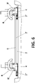
- Figure 8 depicts an embodiment in which the inner shoulders (4) comprise a prolongation surface (5) which allows fastening a rolled iron or steel plate (D) to the inner shoulder (4) itself.
Landscapes
- Engineering & Computer Science (AREA)
- Mechanical Engineering (AREA)
- Architecture (AREA)
- Civil Engineering (AREA)
- Structural Engineering (AREA)
- Connection Of Plates (AREA)
Claims (10)
- Modulare Befestigung für Gleiskreuzungen, umfassend:- eine untere Platte (1), auf der angeordnet ist- eine obere Platte (2), und- eine äußere Flanke (3), die sich an jedem Ende der Platten (1, 2) befindet und Mittel zur Verankerung der Befestigung auf einer Stützfläche (A) umfasst, dadurch gekennzeichnet, dass die Platten (1, 2) und die äußeren Flanken (3) durch Kleben befestigt sind und eine Einheit aus einem Block bilden, wobei- die obere Platte (2) ein glattes Mittelsegment (2') aufweist, das zwischen zwei gerillten Bereichen (2") angeordnet ist, die entsprechend zu den Enden der oberen Platte (2) angeordnet sind,- die Befestigung ferner zwei innere Flanken (4) umfasst, die untere Rillen (4') aufweisen, die in mehreren Positionen in die gerillten Bereiche (2") der oberen Platte (2) eingreifen und passen können, wobei die inneren Flanken (4) Mittel zur Aufnahme und Befestigung einer elastischen Befestigungsklammer (B) zur Befestigung einer Eisenbahnschiene Schiene (C) umfassen.
- Modulare Befestigung nach Anspruch 1, wobei die untere Platte (1) und die obere Platte (2) Metallplatten sind.
- Modulare Befestigung nach einem der vorhergehenden Ansprüche, wobei die obere Platte (2) einen Längskanal (2"') aufweist, der von einem gerillten Bereich (2") zum gegenüberliegenden gerillten Bereich (2") verläuft und durch das glatte Mittelsegment (2') geht, wobei die inneren Flanken (4) entsprechend zu den unteren Rillen (4') einen brückenartigen Führungskanal (4") aufweisen.
- Modulare Befestigung nach Anspruch 3, dadurch gekennzeichnet, dass der brückenartige Führungskanal (4") jeder inneren Flanke (4) einen unteren Vorsprung (4"') aufweist, der in dem Längskanal (2‴) der oberen Platte untergebracht und geführt bewegt werden kann.
- Modulare Befestigung nach einem der Ansprüche 3 bis 4, wobei das glatte Mittelsegment (2') der oberen Platte (2) eine Höhe aufweist, die größer ist als die Höhe der gerillten Bereiche (2").
- Modulare Befestigung nach einem der vorhergehenden Ansprüche, wobei das glatte Mittelsegment (2') der oberen Platte (2) an seinem oberen Teil eine Grundplatte (6) für die Schiene (C) aufweist, wobei die Grundplatte (6) zwei größere Seiten und zwei kleinere Seiten aufweist und die Länge jeder der größeren Seiten mit der Länge des glatten Mittelsegments (2') der oberen Platte (2) übereinstimmt.
- Modulare Befestigung nach einem der Ansprüche 1 bis 5, wobei das glatte Mittelsegment (2') der oberen Platte (2) an seinem oberen Teil eine Grundplatte (6) für die Schiene (C) aufweist, wobei die Grundplatte (6) zwei größere Seiten und zwei kleinere Seiten aufweist, wobei die Länge des glatten mittleren Segments (2') kleiner ist als die Länge jeder der größeren Seiten der Grundplatte (6).
- Modulare Befestigung nach einem der Ansprüche 6 bis 7, wobei die kleineren Seiten der Grundplatte (6) in Bezug auf die größeren Seiten eingezogen sind und entsprechende Passbereiche in Bezug auf jede der inneren Flanken (4) definieren.
- Modulare Befestigung nach einem der vorhergehenden Ansprüche, wobei die Mittel zur Aufnahme der elastischen Klammer (B) einen länglichen Hohlraum (7), der auf einer Seite der inneren Flanken (4) ausgebildet ist, um die gekrümmten äußeren Bereiche (B') der elastischen Klammer (B) zu stützen, einen zentralen erhöhten Bereich (8) in dem länglichen Hohlraum (7), der die gekrümmten äußeren Bereiche (B') trennt und als seitlicher Anschlag für die äußeren Bereiche wirkt, und ein zentrales Durchgangsloch (9) für die Schraube zur Befestigung der elastischen Klammer (B) an der Schiene (C) und der eigentlichen inneren Flanke (4) an der oberen Platte (2) aufweisen.
- Modulare Befestigung nach Anspruch 9, wobei die inneren Flanken (4) eine Verlängerungsfläche (5) aufweisen, die die Befestigung einer gewalzten Eisen- oder Stahlplatte (D) an der inneren Flanke (4) selbst ermöglicht.
Applications Claiming Priority (1)
| Application Number | Priority Date | Filing Date | Title |
|---|---|---|---|
| PCT/ES2018/070085 WO2019149972A1 (es) | 2018-02-05 | 2018-02-05 | Fijación modular para cruces de vías férreas |
Publications (2)
| Publication Number | Publication Date |
|---|---|
| EP3751053A1 EP3751053A1 (de) | 2020-12-16 |
| EP3751053B1 true EP3751053B1 (de) | 2022-04-06 |
Family
ID=62025888
Family Applications (1)
| Application Number | Title | Priority Date | Filing Date |
|---|---|---|---|
| EP18718870.1A Active EP3751053B1 (de) | 2018-02-05 | 2018-02-05 | Modulare befestigung für eisenbahnkreuzungen |
Country Status (5)
| Country | Link |
|---|---|
| US (1) | US12012700B2 (de) |
| EP (1) | EP3751053B1 (de) |
| ES (1) | ES2922106T3 (de) |
| MX (1) | MX2020008233A (de) |
| WO (1) | WO2019149972A1 (de) |
Families Citing this family (1)
| Publication number | Priority date | Publication date | Assignee | Title |
|---|---|---|---|---|
| ES2959826T3 (es) * | 2019-05-24 | 2024-02-28 | Pandrol Iberica S A U | Fijación modular para cruces de vías |
Family Cites Families (5)
| Publication number | Priority date | Publication date | Assignee | Title |
|---|---|---|---|---|
| US4615484A (en) * | 1985-05-20 | 1986-10-07 | San Francisco Bay Area Rapid Transit District | Insulative protective device for rail fastener |
| ES1058662Y (es) * | 2004-10-26 | 2005-05-01 | Suministros Para Ferrocarriles | Placa soporte para rail ferroviario. |
| FR2899606B1 (fr) * | 2006-04-06 | 2008-06-20 | Vossloh Cogifer Sa | Dispositif d'adaptation des platines de fixation de rails dans les zones d'entree et/ou de sortie de coeur et de sortie d'aiguillage des appareils de voie |
| ES2629691T3 (es) * | 2011-05-26 | 2017-08-14 | Railtech Sufetra, S.A. | Conjunto de fijación para raíles de vías férreas |
| US8919660B2 (en) * | 2013-02-20 | 2014-12-30 | Amsted Rps | End restraint for turnout |
-
2018
- 2018-02-05 MX MX2020008233A patent/MX2020008233A/es unknown
- 2018-02-05 ES ES18718870T patent/ES2922106T3/es active Active
- 2018-02-05 EP EP18718870.1A patent/EP3751053B1/de active Active
- 2018-02-05 US US16/967,722 patent/US12012700B2/en active Active
- 2018-02-05 WO PCT/ES2018/070085 patent/WO2019149972A1/es not_active Ceased
Also Published As
| Publication number | Publication date |
|---|---|
| EP3751053A1 (de) | 2020-12-16 |
| MX2020008233A (es) | 2021-01-29 |
| WO2019149972A1 (es) | 2019-08-08 |
| ES2922106T3 (es) | 2022-09-08 |
| US20210040697A1 (en) | 2021-02-11 |
| US12012700B2 (en) | 2024-06-18 |
Similar Documents
| Publication | Publication Date | Title |
|---|---|---|
| US8608116B2 (en) | Adjustable guard rail system for railroad turnouts | |
| EP3751053B1 (de) | Modulare befestigung für eisenbahnkreuzungen | |
| US5560571A (en) | Reversible wing insert frog | |
| EP3978684B1 (de) | Modulare befestigung für bahnübergänge | |
| JP5629145B2 (ja) | 車輪ガード装置 | |
| KR101669437B1 (ko) | 침목매립형 거더 및 그 시공방법 | |
| DE10301897A1 (de) | Exakte Lagerung der Betonfertigteilplatten des Fahrweges einer Magnetschwebebahn auf einem Träger | |
| US6119988A (en) | Flat and planar match system between rails and fillers to railroad turnouts and crossings | |
| US8418970B2 (en) | Swing nose crossing | |
| KR20170138704A (ko) | 결합방식의 매립형 궤도 | |
| KR20100106821A (ko) | 안내 궤도가 설치되는 지지대용 거푸집 | |
| EP2530201B1 (de) | Strassenbahnkreuzung mit beweglichem punkt | |
| US1044508A (en) | Railway-frog. | |
| DE10254973A1 (de) | Rahmenschwelle mit variabler Anzahl von Schienenbefestigungen und Verfahren zur Herstellung der Schwelle | |
| ES2701130T3 (es) | Juego de piezas de ajuste entre una losa y las vías de rodadura ferroviaria o sobre neumáticos | |
| CN217923063U (zh) | 一种单向桥梁伸缩缝装置 | |
| US559284A (en) | Railroad-crossing | |
| KR102042582B1 (ko) | 탈선 방지를 위한 분기기용 망간크로싱 | |
| US7261259B2 (en) | Flared railway frog | |
| US658360A (en) | Railway-track structure. | |
| CN210886772U (zh) | 砼枕道岔用轨撑 | |
| US2609148A (en) | Rail chair | |
| US348877A (en) | Henry paeke adams | |
| US520861A (en) | o shea | |
| KR20160049137A (ko) | 탈선 열차의 진로를 제어하는 시스템 |
Legal Events
| Date | Code | Title | Description |
|---|---|---|---|
| STAA | Information on the status of an ep patent application or granted ep patent |
Free format text: STATUS: UNKNOWN |
|
| STAA | Information on the status of an ep patent application or granted ep patent |
Free format text: STATUS: THE INTERNATIONAL PUBLICATION HAS BEEN MADE |
|
| PUAI | Public reference made under article 153(3) epc to a published international application that has entered the european phase |
Free format text: ORIGINAL CODE: 0009012 |
|
| STAA | Information on the status of an ep patent application or granted ep patent |
Free format text: STATUS: REQUEST FOR EXAMINATION WAS MADE |
|
| 17P | Request for examination filed |
Effective date: 20200904 |
|
| AK | Designated contracting states |
Kind code of ref document: A1 Designated state(s): AL AT BE BG CH CY CZ DE DK EE ES FI FR GB GR HR HU IE IS IT LI LT LU LV MC MK MT NL NO PL PT RO RS SE SI SK SM TR |
|
| AX | Request for extension of the european patent |
Extension state: BA ME |
|
| DAV | Request for validation of the european patent (deleted) | ||
| DAX | Request for extension of the european patent (deleted) | ||
| GRAP | Despatch of communication of intention to grant a patent |
Free format text: ORIGINAL CODE: EPIDOSNIGR1 |
|
| STAA | Information on the status of an ep patent application or granted ep patent |
Free format text: STATUS: GRANT OF PATENT IS INTENDED |
|
| INTG | Intention to grant announced |
Effective date: 20211027 |
|
| GRAS | Grant fee paid |
Free format text: ORIGINAL CODE: EPIDOSNIGR3 |
|
| GRAA | (expected) grant |
Free format text: ORIGINAL CODE: 0009210 |
|
| STAA | Information on the status of an ep patent application or granted ep patent |
Free format text: STATUS: THE PATENT HAS BEEN GRANTED |
|
| AK | Designated contracting states |
Kind code of ref document: B1 Designated state(s): AL AT BE BG CH CY CZ DE DK EE ES FI FR GB GR HR HU IE IS IT LI LT LU LV MC MK MT NL NO PL PT RO RS SE SI SK SM TR |
|
| REG | Reference to a national code |
Ref country code: GB Ref legal event code: FG4D |
|
| REG | Reference to a national code |
Ref country code: CH Ref legal event code: EP |
|
| REG | Reference to a national code |
Ref country code: AT Ref legal event code: REF Ref document number: 1481441 Country of ref document: AT Kind code of ref document: T Effective date: 20220415 |
|
| REG | Reference to a national code |
Ref country code: DE Ref legal event code: R096 Ref document number: 602018033349 Country of ref document: DE |
|
| REG | Reference to a national code |
Ref country code: IE Ref legal event code: FG4D |
|
| REG | Reference to a national code |
Ref country code: LT Ref legal event code: MG9D |
|
| REG | Reference to a national code |
Ref country code: NL Ref legal event code: MP Effective date: 20220406 |
|
| REG | Reference to a national code |
Ref country code: ES Ref legal event code: FG2A Ref document number: 2922106 Country of ref document: ES Kind code of ref document: T3 Effective date: 20220908 |
|
| REG | Reference to a national code |
Ref country code: AT Ref legal event code: MK05 Ref document number: 1481441 Country of ref document: AT Kind code of ref document: T Effective date: 20220406 |
|
| PG25 | Lapsed in a contracting state [announced via postgrant information from national office to epo] |
Ref country code: NL Free format text: LAPSE BECAUSE OF FAILURE TO SUBMIT A TRANSLATION OF THE DESCRIPTION OR TO PAY THE FEE WITHIN THE PRESCRIBED TIME-LIMIT Effective date: 20220406 |
|
| PG25 | Lapsed in a contracting state [announced via postgrant information from national office to epo] |
Ref country code: SE Free format text: LAPSE BECAUSE OF FAILURE TO SUBMIT A TRANSLATION OF THE DESCRIPTION OR TO PAY THE FEE WITHIN THE PRESCRIBED TIME-LIMIT Effective date: 20220406 Ref country code: PT Free format text: LAPSE BECAUSE OF FAILURE TO SUBMIT A TRANSLATION OF THE DESCRIPTION OR TO PAY THE FEE WITHIN THE PRESCRIBED TIME-LIMIT Effective date: 20220808 Ref country code: NO Free format text: LAPSE BECAUSE OF FAILURE TO SUBMIT A TRANSLATION OF THE DESCRIPTION OR TO PAY THE FEE WITHIN THE PRESCRIBED TIME-LIMIT Effective date: 20220706 Ref country code: LT Free format text: LAPSE BECAUSE OF FAILURE TO SUBMIT A TRANSLATION OF THE DESCRIPTION OR TO PAY THE FEE WITHIN THE PRESCRIBED TIME-LIMIT Effective date: 20220406 Ref country code: HR Free format text: LAPSE BECAUSE OF FAILURE TO SUBMIT A TRANSLATION OF THE DESCRIPTION OR TO PAY THE FEE WITHIN THE PRESCRIBED TIME-LIMIT Effective date: 20220406 Ref country code: GR Free format text: LAPSE BECAUSE OF FAILURE TO SUBMIT A TRANSLATION OF THE DESCRIPTION OR TO PAY THE FEE WITHIN THE PRESCRIBED TIME-LIMIT Effective date: 20220707 Ref country code: FI Free format text: LAPSE BECAUSE OF FAILURE TO SUBMIT A TRANSLATION OF THE DESCRIPTION OR TO PAY THE FEE WITHIN THE PRESCRIBED TIME-LIMIT Effective date: 20220406 Ref country code: BG Free format text: LAPSE BECAUSE OF FAILURE TO SUBMIT A TRANSLATION OF THE DESCRIPTION OR TO PAY THE FEE WITHIN THE PRESCRIBED TIME-LIMIT Effective date: 20220706 Ref country code: AT Free format text: LAPSE BECAUSE OF FAILURE TO SUBMIT A TRANSLATION OF THE DESCRIPTION OR TO PAY THE FEE WITHIN THE PRESCRIBED TIME-LIMIT Effective date: 20220406 |
|
| PG25 | Lapsed in a contracting state [announced via postgrant information from national office to epo] |
Ref country code: RS Free format text: LAPSE BECAUSE OF FAILURE TO SUBMIT A TRANSLATION OF THE DESCRIPTION OR TO PAY THE FEE WITHIN THE PRESCRIBED TIME-LIMIT Effective date: 20220406 Ref country code: PL Free format text: LAPSE BECAUSE OF FAILURE TO SUBMIT A TRANSLATION OF THE DESCRIPTION OR TO PAY THE FEE WITHIN THE PRESCRIBED TIME-LIMIT Effective date: 20220406 Ref country code: LV Free format text: LAPSE BECAUSE OF FAILURE TO SUBMIT A TRANSLATION OF THE DESCRIPTION OR TO PAY THE FEE WITHIN THE PRESCRIBED TIME-LIMIT Effective date: 20220406 Ref country code: IS Free format text: LAPSE BECAUSE OF FAILURE TO SUBMIT A TRANSLATION OF THE DESCRIPTION OR TO PAY THE FEE WITHIN THE PRESCRIBED TIME-LIMIT Effective date: 20220806 |
|
| REG | Reference to a national code |
Ref country code: DE Ref legal event code: R097 Ref document number: 602018033349 Country of ref document: DE |
|
| PG25 | Lapsed in a contracting state [announced via postgrant information from national office to epo] |
Ref country code: SM Free format text: LAPSE BECAUSE OF FAILURE TO SUBMIT A TRANSLATION OF THE DESCRIPTION OR TO PAY THE FEE WITHIN THE PRESCRIBED TIME-LIMIT Effective date: 20220406 Ref country code: SK Free format text: LAPSE BECAUSE OF FAILURE TO SUBMIT A TRANSLATION OF THE DESCRIPTION OR TO PAY THE FEE WITHIN THE PRESCRIBED TIME-LIMIT Effective date: 20220406 Ref country code: RO Free format text: LAPSE BECAUSE OF FAILURE TO SUBMIT A TRANSLATION OF THE DESCRIPTION OR TO PAY THE FEE WITHIN THE PRESCRIBED TIME-LIMIT Effective date: 20220406 Ref country code: EE Free format text: LAPSE BECAUSE OF FAILURE TO SUBMIT A TRANSLATION OF THE DESCRIPTION OR TO PAY THE FEE WITHIN THE PRESCRIBED TIME-LIMIT Effective date: 20220406 Ref country code: DK Free format text: LAPSE BECAUSE OF FAILURE TO SUBMIT A TRANSLATION OF THE DESCRIPTION OR TO PAY THE FEE WITHIN THE PRESCRIBED TIME-LIMIT Effective date: 20220406 Ref country code: CZ Free format text: LAPSE BECAUSE OF FAILURE TO SUBMIT A TRANSLATION OF THE DESCRIPTION OR TO PAY THE FEE WITHIN THE PRESCRIBED TIME-LIMIT Effective date: 20220406 |
|
| PLBE | No opposition filed within time limit |
Free format text: ORIGINAL CODE: 0009261 |
|
| STAA | Information on the status of an ep patent application or granted ep patent |
Free format text: STATUS: NO OPPOSITION FILED WITHIN TIME LIMIT |
|
| 26N | No opposition filed |
Effective date: 20230110 |
|
| PG25 | Lapsed in a contracting state [announced via postgrant information from national office to epo] |
Ref country code: AL Free format text: LAPSE BECAUSE OF FAILURE TO SUBMIT A TRANSLATION OF THE DESCRIPTION OR TO PAY THE FEE WITHIN THE PRESCRIBED TIME-LIMIT Effective date: 20220406 |
|
| PG25 | Lapsed in a contracting state [announced via postgrant information from national office to epo] |
Ref country code: SI Free format text: LAPSE BECAUSE OF FAILURE TO SUBMIT A TRANSLATION OF THE DESCRIPTION OR TO PAY THE FEE WITHIN THE PRESCRIBED TIME-LIMIT Effective date: 20220406 |
|
| P01 | Opt-out of the competence of the unified patent court (upc) registered |
Effective date: 20230602 |
|
| PG25 | Lapsed in a contracting state [announced via postgrant information from national office to epo] |
Ref country code: MC Free format text: LAPSE BECAUSE OF FAILURE TO SUBMIT A TRANSLATION OF THE DESCRIPTION OR TO PAY THE FEE WITHIN THE PRESCRIBED TIME-LIMIT Effective date: 20220406 |
|
| REG | Reference to a national code |
Ref country code: BE Ref legal event code: MM Effective date: 20230228 |
|
| PG25 | Lapsed in a contracting state [announced via postgrant information from national office to epo] |
Ref country code: LU Free format text: LAPSE BECAUSE OF NON-PAYMENT OF DUE FEES Effective date: 20230205 |
|
| REG | Reference to a national code |
Ref country code: IE Ref legal event code: MM4A |
|
| PG25 | Lapsed in a contracting state [announced via postgrant information from national office to epo] |
Ref country code: IE Free format text: LAPSE BECAUSE OF NON-PAYMENT OF DUE FEES Effective date: 20230205 |
|
| PG25 | Lapsed in a contracting state [announced via postgrant information from national office to epo] |
Ref country code: BE Free format text: LAPSE BECAUSE OF NON-PAYMENT OF DUE FEES Effective date: 20230228 |
|
| PG25 | Lapsed in a contracting state [announced via postgrant information from national office to epo] |
Ref country code: BG Free format text: LAPSE BECAUSE OF FAILURE TO SUBMIT A TRANSLATION OF THE DESCRIPTION OR TO PAY THE FEE WITHIN THE PRESCRIBED TIME-LIMIT Effective date: 20220406 |
|
| PG25 | Lapsed in a contracting state [announced via postgrant information from national office to epo] |
Ref country code: BG Free format text: LAPSE BECAUSE OF FAILURE TO SUBMIT A TRANSLATION OF THE DESCRIPTION OR TO PAY THE FEE WITHIN THE PRESCRIBED TIME-LIMIT Effective date: 20220406 |
|
| PGFP | Annual fee paid to national office [announced via postgrant information from national office to epo] |
Ref country code: CH Payment date: 20250301 Year of fee payment: 8 |
|
| PG25 | Lapsed in a contracting state [announced via postgrant information from national office to epo] |
Ref country code: CY Free format text: LAPSE BECAUSE OF FAILURE TO SUBMIT A TRANSLATION OF THE DESCRIPTION OR TO PAY THE FEE WITHIN THE PRESCRIBED TIME-LIMIT; INVALID AB INITIO Effective date: 20180205 |
|
| PG25 | Lapsed in a contracting state [announced via postgrant information from national office to epo] |
Ref country code: HU Free format text: LAPSE BECAUSE OF FAILURE TO SUBMIT A TRANSLATION OF THE DESCRIPTION OR TO PAY THE FEE WITHIN THE PRESCRIBED TIME-LIMIT; INVALID AB INITIO Effective date: 20180205 |
|
| PG25 | Lapsed in a contracting state [announced via postgrant information from national office to epo] |
Ref country code: TR Free format text: LAPSE BECAUSE OF FAILURE TO SUBMIT A TRANSLATION OF THE DESCRIPTION OR TO PAY THE FEE WITHIN THE PRESCRIBED TIME-LIMIT Effective date: 20220406 |
|
| REG | Reference to a national code |
Ref country code: CH Ref legal event code: U11 Free format text: ST27 STATUS EVENT CODE: U-0-0-U10-U11 (AS PROVIDED BY THE NATIONAL OFFICE) Effective date: 20260301 |
|
| PGFP | Annual fee paid to national office [announced via postgrant information from national office to epo] |
Ref country code: GB Payment date: 20260115 Year of fee payment: 9 |
|
| PGFP | Annual fee paid to national office [announced via postgrant information from national office to epo] |
Ref country code: ES Payment date: 20260302 Year of fee payment: 9 |
|
| PGFP | Annual fee paid to national office [announced via postgrant information from national office to epo] |
Ref country code: DE Payment date: 20260218 Year of fee payment: 9 |
|
| PGFP | Annual fee paid to national office [announced via postgrant information from national office to epo] |
Ref country code: IT Payment date: 20260224 Year of fee payment: 9 |
|
| PGFP | Annual fee paid to national office [announced via postgrant information from national office to epo] |
Ref country code: FR Payment date: 20260120 Year of fee payment: 9 |