EP3978684B1 - Modulare befestigung für bahnübergänge - Google Patents
Modulare befestigung für bahnübergänge Download PDFInfo
- Publication number
- EP3978684B1 EP3978684B1 EP19734837.8A EP19734837A EP3978684B1 EP 3978684 B1 EP3978684 B1 EP 3978684B1 EP 19734837 A EP19734837 A EP 19734837A EP 3978684 B1 EP3978684 B1 EP 3978684B1
- Authority
- EP
- European Patent Office
- Prior art keywords
- plate
- rail
- lower plate
- assembly
- face
- Prior art date
- Legal status (The legal status is an assumption and is not a legal conclusion. Google has not performed a legal analysis and makes no representation as to the accuracy of the status listed.)
- Active
Links
Images


Classifications
-
- E—FIXED CONSTRUCTIONS
- E01—CONSTRUCTION OF ROADS, RAILWAYS, OR BRIDGES
- E01B—PERMANENT WAY; PERMANENT-WAY TOOLS; MACHINES FOR MAKING RAILWAYS OF ALL KINDS
- E01B7/00—Switches; Crossings
- E01B7/22—Special sleepers for switches or crossings; Fastening means therefor
-
- E—FIXED CONSTRUCTIONS
- E01—CONSTRUCTION OF ROADS, RAILWAYS, OR BRIDGES
- E01B—PERMANENT WAY; PERMANENT-WAY TOOLS; MACHINES FOR MAKING RAILWAYS OF ALL KINDS
- E01B9/00—Fastening rails on sleepers, or the like
- E01B9/02—Fastening rails, tie-plates, or chairs directly on sleepers or foundations; Means therefor
- E01B9/28—Fastening on wooden or concrete sleepers or on masonry with clamp members
- E01B9/30—Fastening on wooden or concrete sleepers or on masonry with clamp members by resilient steel clips
- E01B9/303—Fastening on wooden or concrete sleepers or on masonry with clamp members by resilient steel clips the clip being a shaped bar
-
- E—FIXED CONSTRUCTIONS
- E01—CONSTRUCTION OF ROADS, RAILWAYS, OR BRIDGES
- E01B—PERMANENT WAY; PERMANENT-WAY TOOLS; MACHINES FOR MAKING RAILWAYS OF ALL KINDS
- E01B9/00—Fastening rails on sleepers, or the like
- E01B9/38—Indirect fastening of rails by using tie-plates or chairs; Fastening of rails on the tie-plates or in the chairs
Definitions
- the present invention relates to a modular fastening for track crossings, having an application in the railway industry, and more specifically in the field of fastenings for turnouts on the outside of the switch diamond of the track, i.e., at an intersecting point of the two rails where two independent rails are required to be borne on a plate, the separation and orientation of which rails varies depending on the different support points of the rails along the track.
- the invention allows fixing the rails in a quick and simple manner by means of a highly versatile fastening which, by means of a set number of identical elements in all the fastenings, allows the adaptation thereof to the different orientations and separations existing between rails along different points of the line layout, with the subsequent reduction in the costs of manufacturing and storing the fastenings needed to cover an entire segment of the intersection.
- the track frog is a critical region of railway track crossing areas that is of great importance in turnout safety.
- the track frog corresponds with the central part of the crossing in which the rails come together to form a single rail, and it has the function of correctly guiding the wheels of the railway vehicle in the rail intersection or crossing.
- said area may have different rail profiles, gradients, clips and securing plate sizes, resulting in major problems occurring during switching operations.
- frog plates Plates, referred to as frog plates, comprising two inner shoulders that serve to fasten elastic rail securing clips are used today for securing or fastening rails in the track frog.
- the position of said inner shoulders in said plates is established in a predetermined manner according to the width of the rail. Therefore, the distance between the inner shoulders of a frog plate and the distance between consecutive or adjacent plates in the mentioned segment are different, which requires providing and using a wide range of plates with different distances between inner shoulders according to the distance required in each frog plate.
- Frog plates usually comprise a metal bearing or lower plate, an upper plate, also of metal, and two anchoring end side shoulders.
- the metal upper plate there is a need to machine the edges, define the positioning of second shoulders, in this case inner shoulders, the position of which is determined according to the width and number of rails, make the corresponding boreholes, weld said second shoulders to the upper plate and finally subject the assembly formed by the upper plate, lower plate and end shoulders to a vulcanization or adhesive bonding phase, forming a fastening that is made as a single compact block on which fastening elements such as screws, nuts and clips are then arranged for fastening the rail.
- EP-A-3290583 discloses a modular fastening for track crossings with the features of the preamble of claim 1.
- frog plates are commonly used according to their size, i.e., long, medium and short length type, which plates are obtained by casting and are subsequently vulcanized.
- each type of plate has a specific, predefined distance between the inner shoulders according to the position thereof in the track frog, with the drawbacks this entails in terms of production cost, storage cost and assembly complication.
- a track requires the use of a reinforcement referred to as rolled iron or steel plate, consisting of a stiffening rod arranged between two tracks to provide greater stability, the positioning of which must also be defined, the corresponding holes made, welding carried out and the adhesive bonding with the aforementioned assembly performed.
- a reinforcement referred to as rolled iron or steel plate, consisting of a stiffening rod arranged between two tracks to provide greater stability, the positioning of which must also be defined, the corresponding holes made, welding carried out and the adhesive bonding with the aforementioned assembly performed.
- the drawbacks of the frog plates described above include, among others, the fact that the processes for obtaining them are expensive and complex in terms of manufacturing operations. Additionally, they are subject to a plurality of variations in the positioning and the boreholes required for the elements involved, resulting in the need for multiple plate references according to the width and/or number of rails in this track frog segment.
- the present invention relates to a modular fastening for track crossings, which allows the independent orientation of two plate assemblies, mounted on one and the same lower plate, such that it allows the adaptation thereof to a variable orientation of the two rails supported on the same plate along different points of the layout.
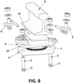
- the modular fastening for track crossings proposed by the invention comprises a lower plate and a shoulder attached by means of adhesive bonding to each end of the lower plate, forming a single-block assembly.
- each shoulder comprises means for anchoring the fastening on a support surface.
- the lower plate comprises a central segment running between the shoulders on a face above the face for anchoring to the support surface.
- the fastening comprises two plate assemblies.
- Each plate assembly can be mounted on the lower plate by means of two rail spikes going through the plate assembly and allows the fixing of a rail.
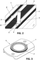
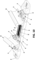
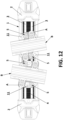
- each plate assembly comprises an intermediate plate the lower face of which comprises a recess for the fitting thereof on the central segment of the lower plate, and the upper face of which comprises a circular projection configured for fitting in a circular recess located on a lower face of an upper plate on which a rail can be supported, such that said upper plate can be oriented with respect to said intermediate plate.
- the upper plate comprises at least two curved elongated holes, preferably one on each side of the rail and diametrically opposed to one another, allowing play of the rail spikes mounting the plate assembly on the lower plate.
- the area of the circular projection allows the positioning of the homologous area arranged on the lower face of the upper plate, whereas the recess of the lower face of the intermediate plate allows the fitting thereof in the lower plate on the central segment and the areas demarcating the guides defined below.
- the intermediate plate is a metal plate.
- the upper plate can be made of metal or plastic and comprises the curved elongated holes curving towards the inner portion of the plate itself, which allows adapting the orientation thereof.
- the circular fitting and coupling segments between the upper and intermediate plates allow the latter to rotate one above the other in different positions, such that the curved elongated holes enable the adjustment by different degrees in both fastening assemblies for adapting them in an independent manner to rail orientation changes at a turnout.
- the degrees are determined depending on the curvature of the elongated holes, comprised between 0° and 15°, usually about 10°.
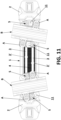
- the lower plate may comprise two parallel guides located in the central segment, running from one of the shoulders to the opposite shoulder, each guide comprising at least one enlargement which allows the insertion of a head of a rail spike for mounting each plate assembly, which allows regulation for adaptation thereof to the different separations between rails at different points of the line layout.
- the proposed fastening comprises two parallel longitudinal guides separated by a central segment, such that the guides allow the insertion of the head of respective rail spikes for fastening the plate assemblies to one another, and they also serve for cooperating with the elongated holes for regulating orientation.
- each guide preferably comprises at least one enlargement or notch, such that once the heads are inserted and by means of the rotation thereof of 90°, they are coupled in said guides with the possibility of being moved longitudinally along the guides.
- two coach screws located in different guides go through each plate assembly.
- the recesses comprise grooved areas collaborating with corresponding grooved areas comprised in the central segment of the lower plate.
- the grooved parts are for cooperating with the recessed area of the intermediate plate, for acting during longitudinal movements of each plate (intermediate and upper) assembly with respect to the lower plate.
- each upper plate may comprise a toothing collaborating with a corresponding grooving comprised in the annular projection of each intermediate plate.
- a smooth segment on the upper face of the upper plate is suitable for placing in the upper portion a protective base plate.
- the upper plate comprises two slots, each for housing an elastic clip is contemplated, where each slot comprises a hole into which a screw can be inserted for mounting said elastic clip.
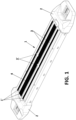
- the modular fastening for track crossings proposed by the invention comprises a lower plate (1) and a shoulder (2) attached by means of adhesive bonding to each end of the lower plate (1), forming a single-block assembly, where each shoulder (2) comprises means for anchoring the fastening on a support surface, the lower plate (1) comprising a central segment (4) running between the shoulders (2) on a face above the face for anchoring to the support surface.
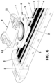
- the fastening comprises two plate assemblies (6, 9), where each plate assembly (6, 9) can be mounted on the lower plate (1) by means of two rail spikes (5) going through the plate assembly (6, 9) and allows the fixing to a rail (B), each plate assembly (6, 9) comprising an intermediate plate (6) the lower face of which comprises a recess (8) for the fitting thereof on the central segment (4) of the lower plate (1), and the upper face of which comprises a circular projection (7) configured for fitting in a circular recess (10) located on a lower face of an upper plate (9) on which a rail (B) can be supported, such that said upper plate (9) can be oriented with respect to said intermediate plate (6).
- Each upper plate (9) comprises two curved elongated holes (11) allowing play of the rail spikes (5) mounting the plate assembly (6, 9) on the lower plate (1).
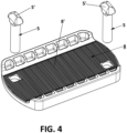
- the lower plate (1) comprises two parallel guides (3) located in the central segment (4), running from one of the shoulders (2) to the opposite shoulder (2), each guide (3) comprising at least one enlargement (3') which allows the insertion of a head (5') of a rail spike (5) for mounting each plate assembly (6, 9).
- the recesses (8) comprise grooved areas (8') collaborating with corresponding grooved areas (1') comprised in the central segment (4) of the lower plate (1).
- the circular recesses (10) of each upper plate (9) comprise a toothing (10') collaborating with a corresponding grooving (7') comprised in the annular projection (7) of each intermediate plate (6).
- the toothing (10') and grooving (7') are made such that they cover the walls defining the perimeter of the respective circular recesses (10) and annular projections (7).
- the upper face of the upper plate (9) comprises a smooth segment suitable for placing in the upper portion a protective base plate (13).
- the upper plate (9) comprises two slots, each for housing an elastic clip (A), where each slot comprises a hole (12) into which a screw can be inserted for mounting said elastic clip (A).
Landscapes
- Engineering & Computer Science (AREA)
- Mechanical Engineering (AREA)
- Architecture (AREA)
- Civil Engineering (AREA)
- Structural Engineering (AREA)
- Connection Of Plates (AREA)
- Braking Arrangements (AREA)
Claims (7)
- Modulare Befestigung für Gleiskreuzungen, umfassend eine untere Platte (1) und eine Schulter (2), die mittels Kleben an jedem Ende der unteren Platte (1) befestigt ist, wodurch eine Einzelblockanordnung gebildet ist, wobei jede Schulter (2) Elemente zur Verankerung der Befestigung auf einer Trägerfläche umfasst, wobei die untere Platte (1) ein zentrales Segment (4) umfasst, das zwischen den Schultern (2) auf einer Fläche oberhalb der Fläche zur Verankerung an der Trägerfläche verläuft, dadurch gekennzeichnet, dass sie zwei Plattenanordnungen (6, 9) umfasst, wobei jede Plattenanordnung (6, 9) auf der unteren Platte (1) mittels zweier Schienennägeln (5) montiert werden kann, die durch die Plattenanordnung (6, 9) verlaufen und die Befestigung einer Schiene (B) ermöglichen, wobei jede Plattenanordnung (6, 9) eine Zwischenplatte (6) und eine obere Platte (9) umfasst, wobei die untere Fläche der Zwischenplatte (6) eine Ausnehmung (8) für deren Montage auf dem zentralen Segment (4) der unteren Platte (1) umfasst, und deren obere Fläche einen kreisförmigen Vorsprung (7) umfasst, der zur Montage in einer kreisförmigen Ausnehmung (10) ausgebildet ist, die sich auf einer unteren Fläche der oberen Platte (9) befindet, auf der eine Schiene (B) getragen werden kann, so dass die obere Platte (9) in Bezug auf die Zwischenplatte (6) ausgerichtet werden kann, wobei die obere Platte (9) mindestens zwei gebogene Langlöcher (11) umfasst, die ein Spiel der Schienennägel (5), die die Plattenanordnung (6, 9) auf der unteren Platte (1) anbringen, ermöglichen.
- Modulare Befestigung nach Anspruch 1, wobei die mindestens zwei gebogenen Langlöcher (11) ein und derselben oberen Platte (9) einander diametral gegenüberliegend angeordnet sind.
- Modulare Befestigung nach einem der vorhergehenden Ansprüche, wobei die untere Platte (1) zwei parallele Führungen (3) umfasst, die sich in dem zentralen Segment (4) befinden und von einer der Schultern (2) zu der gegenüberliegenden Schulter (2) verlaufen, wobei jede Führung (3) mindestens eine Vergrößerung (3') umfasst, die das Einsetzen eines Kopfes (5') eines Schienennagels (5) zum Montieren jeder Plattenanordnung (6, 9) ermöglicht.
- Modulare Befestigung nach Anspruch 3, wobei zwei Schienennägel (5), die sich in verschiedenen Führungen (3) befinden, durch jede Plattenanordnung (6, 9) verlaufen.
- Modulare Befestigung nach einem der vorhergehenden Ansprüche, wobei die Ausnehmungen (8) gerillte Bereiche (8') umfassen, die mit entsprechenden gerillten Bereichen (1') zusammenwirken, die in dem zentralen Segment (4) der unteren Platte (1) enthalten sind.
- Modulare Befestigung nach einem der vorhergehenden Ansprüche, wobei die kreisförmigen Ausnehmungen (10) jeder oberen Platte (9) eine Verzahnung (10') umfassen, die mit einer entsprechenden Rillung (7') zusammenwirkt, die in dem ringförmigen Vorsprung (7) jeder Zwischenplatte (6) enthalten ist.
- Modulare Befestigung nach einem der vorhergehenden Ansprüche, wobei die obere Platte (9) zwei Schlitze umfasst, jeder zur Aufnahme eines elastischen Clips (A), wobei jeder Schlitz ein Loch (12) umfasst, in das eine Schraube zur Montage des elastischen Clips (A) einführbar ist.
Applications Claiming Priority (1)
| Application Number | Priority Date | Filing Date | Title |
|---|---|---|---|
| PCT/ES2019/070346 WO2020240050A1 (es) | 2019-05-24 | 2019-05-24 | Fijación modular para cruces de vías |
Publications (2)
| Publication Number | Publication Date |
|---|---|
| EP3978684A1 EP3978684A1 (de) | 2022-04-06 |
| EP3978684B1 true EP3978684B1 (de) | 2023-08-23 |
Family
ID=67137966
Family Applications (1)
| Application Number | Title | Priority Date | Filing Date |
|---|---|---|---|
| EP19734837.8A Active EP3978684B1 (de) | 2019-05-24 | 2019-05-24 | Modulare befestigung für bahnübergänge |
Country Status (5)
| Country | Link |
|---|---|
| US (1) | US12392091B2 (de) |
| EP (1) | EP3978684B1 (de) |
| CN (1) | CN114174592B (de) |
| ES (1) | ES2959826T3 (de) |
| WO (1) | WO2020240050A1 (de) |
Families Citing this family (1)
| Publication number | Priority date | Publication date | Assignee | Title |
|---|---|---|---|---|
| CN114250655B (zh) * | 2021-11-23 | 2023-07-14 | 中国土木工程集团有限公司 | 一种铁路轨道紧固装置 |
Family Cites Families (20)
| Publication number | Priority date | Publication date | Assignee | Title |
|---|---|---|---|---|
| US837706A (en) * | 1906-06-18 | 1906-12-04 | Charles L Jewett | Tie-plate. |
| US1405607A (en) * | 1921-10-22 | 1922-02-07 | Joseph J Markovich | Rail-tie chair |
| US2235776A (en) | 1938-06-02 | 1941-03-18 | Rushing Herschel Lee | Railway tie plate |
| FR2685364A1 (fr) * | 1991-12-18 | 1993-06-25 | Vagneux Traverses Beton Arme S | Selle et traverse de voie ferree; appareils de voie ferree les comportant. |
| FR2719827A1 (fr) | 1994-05-11 | 1995-11-17 | Bruno Idrac | Bocal à conservation - sous-mise à vide. |
| JPH11350401A (ja) * | 1998-06-04 | 1999-12-21 | Bando Chem Ind Ltd | まくらぎ弾性支持装置及びこの装置を備えたまくらぎ |
| KR20030003623A (ko) * | 2001-07-03 | 2003-01-10 | 전은철 | 레일의 침목구조 |
| CN2649406Y (zh) * | 2003-10-10 | 2004-10-20 | 河南省长葛市通用机械厂 | 大吨位吊车轨道压板 |
| DE102007005722A1 (de) * | 2007-01-31 | 2008-08-07 | Hans Joachim Leithner | Laufrad für einen Axialventilator |
| CN101824780B (zh) * | 2009-02-11 | 2013-10-23 | 沃斯洛工厂有限公司 | 将铁轨紧固至路基的系统的导板及包含该导板的系统 |
| KR101146627B1 (ko) * | 2011-01-18 | 2012-05-16 | 진형건설(주) | 위치이동이 가능한 교량받침용 앵커소켓 구조물 |
| ES2629691T3 (es) * | 2011-05-26 | 2017-08-14 | Railtech Sufetra, S.A. | Conjunto de fijación para raíles de vías férreas |
| KR200473880Y1 (ko) * | 2012-08-01 | 2014-08-07 | 주식회사 에이브이티 | 레일체결장치 |
| CN203284701U (zh) * | 2013-06-19 | 2013-11-13 | 太仓中博铁路紧固件有限公司 | 一种可调整钢轨轨距的弹性扣件 |
| ES2757898T3 (es) | 2016-09-02 | 2020-04-30 | Duro Felguera Rail S A U | Sistema de sujeción modular para raíles |
| CN107217555A (zh) * | 2017-06-29 | 2017-09-29 | 中铁第四勘察设计院集团有限公司 | 具有抗倾覆绝缘垫板的轨道交通用扣件 |
| US10711406B2 (en) * | 2018-01-10 | 2020-07-14 | Voestalpine Nortrak Inc. | Keyway tie |
| MX2020008233A (es) * | 2018-02-05 | 2021-01-29 | Pandrol Iberica S A U | Fijacion modular para cruces de vias ferreas. |
| CN208649810U (zh) * | 2018-06-28 | 2019-03-26 | 洛阳双瑞橡塑科技有限公司 | 一种钢轨扣件系统 |
| CN208589527U (zh) * | 2018-07-20 | 2019-03-08 | 摩比天线技术(深圳)有限公司 | 天线遮蔽固定结构及天线 |
-
2019
- 2019-05-24 ES ES19734837T patent/ES2959826T3/es active Active
- 2019-05-24 US US17/614,330 patent/US12392091B2/en active Active
- 2019-05-24 EP EP19734837.8A patent/EP3978684B1/de active Active
- 2019-05-24 WO PCT/ES2019/070346 patent/WO2020240050A1/es not_active Ceased
- 2019-05-24 CN CN201980098040.5A patent/CN114174592B/zh active Active
Also Published As
| Publication number | Publication date |
|---|---|
| CN114174592A (zh) | 2022-03-11 |
| US12392091B2 (en) | 2025-08-19 |
| CN114174592B (zh) | 2024-10-01 |
| US20220220672A1 (en) | 2022-07-14 |
| WO2020240050A1 (es) | 2020-12-03 |
| ES2959826T3 (es) | 2024-02-28 |
| EP3978684A1 (de) | 2022-04-06 |
Similar Documents
| Publication | Publication Date | Title |
|---|---|---|
| EP3978684B1 (de) | Modulare befestigung für bahnübergänge | |
| MX2011004104A (es) | Sistema de contrariel para cambio de via ferrea. | |
| EP3751053B1 (de) | Modulare befestigung für eisenbahnkreuzungen | |
| WO2013053972A2 (es) | Sistema de posicionamiento de un raíl | |
| US6254038B1 (en) | Flat and planar match system between rails and fillers to railroad turnouts and crossings | |
| JP2012012772A (ja) | 車輪ガード装置 | |
| US5765785A (en) | Standard crossing for railroad track with interchangeable insert | |
| US1044508A (en) | Railway-frog. | |
| US559284A (en) | Railroad-crossing | |
| US653845A (en) | Railway-track structure. | |
| US20240229365A1 (en) | Assembly comprising at least one rail and a support | |
| US520861A (en) | o shea | |
| US71905A (en) | Staats n | |
| US747955A (en) | Railway-frog. | |
| US793990A (en) | Railway-switch. | |
| US1088975A (en) | Guard-rail. | |
| US1151097A (en) | Adjustable block for frogs. | |
| US551691A (en) | Otto r | |
| US2611077A (en) | Steel frog tie with special clips | |
| US627544A (en) | Railway-track structure. | |
| US658360A (en) | Railway-track structure. | |
| US526455A (en) | Railway-cross | |
| US536734A (en) | Railway-switch work | |
| US873761A (en) | Railway-switch structure. | |
| US534172A (en) | Rail-clamp |
Legal Events
| Date | Code | Title | Description |
|---|---|---|---|
| STAA | Information on the status of an ep patent application or granted ep patent |
Free format text: STATUS: UNKNOWN |
|
| STAA | Information on the status of an ep patent application or granted ep patent |
Free format text: STATUS: THE INTERNATIONAL PUBLICATION HAS BEEN MADE |
|
| PUAI | Public reference made under article 153(3) epc to a published international application that has entered the european phase |
Free format text: ORIGINAL CODE: 0009012 |
|
| STAA | Information on the status of an ep patent application or granted ep patent |
Free format text: STATUS: REQUEST FOR EXAMINATION WAS MADE |
|
| 17P | Request for examination filed |
Effective date: 20211124 |
|
| AK | Designated contracting states |
Kind code of ref document: A1 Designated state(s): AL AT BE BG CH CY CZ DE DK EE ES FI FR GB GR HR HU IE IS IT LI LT LU LV MC MK MT NL NO PL PT RO RS SE SI SK SM TR |
|
| DAV | Request for validation of the european patent (deleted) | ||
| DAX | Request for extension of the european patent (deleted) | ||
| GRAP | Despatch of communication of intention to grant a patent |
Free format text: ORIGINAL CODE: EPIDOSNIGR1 |
|
| STAA | Information on the status of an ep patent application or granted ep patent |
Free format text: STATUS: GRANT OF PATENT IS INTENDED |
|
| INTG | Intention to grant announced |
Effective date: 20230328 |
|
| P01 | Opt-out of the competence of the unified patent court (upc) registered |
Effective date: 20230602 |
|
| GRAS | Grant fee paid |
Free format text: ORIGINAL CODE: EPIDOSNIGR3 |
|
| GRAA | (expected) grant |
Free format text: ORIGINAL CODE: 0009210 |
|
| STAA | Information on the status of an ep patent application or granted ep patent |
Free format text: STATUS: THE PATENT HAS BEEN GRANTED |
|
| AK | Designated contracting states |
Kind code of ref document: B1 Designated state(s): AL AT BE BG CH CY CZ DE DK EE ES FI FR GB GR HR HU IE IS IT LI LT LU LV MC MK MT NL NO PL PT RO RS SE SI SK SM TR |
|
| REG | Reference to a national code |
Ref country code: GB Ref legal event code: FG4D |
|
| REG | Reference to a national code |
Ref country code: CH Ref legal event code: EP |
|
| REG | Reference to a national code |
Ref country code: DE Ref legal event code: R096 Ref document number: 602019035602 Country of ref document: DE |
|
| REG | Reference to a national code |
Ref country code: IE Ref legal event code: FG4D |
|
| REG | Reference to a national code |
Ref country code: LT Ref legal event code: MG9D |
|
| REG | Reference to a national code |
Ref country code: NL Ref legal event code: MP Effective date: 20230823 |
|
| REG | Reference to a national code |
Ref country code: AT Ref legal event code: MK05 Ref document number: 1602724 Country of ref document: AT Kind code of ref document: T Effective date: 20230823 |
|
| PG25 | Lapsed in a contracting state [announced via postgrant information from national office to epo] |
Ref country code: GR Free format text: LAPSE BECAUSE OF FAILURE TO SUBMIT A TRANSLATION OF THE DESCRIPTION OR TO PAY THE FEE WITHIN THE PRESCRIBED TIME-LIMIT Effective date: 20231124 |
|
| PG25 | Lapsed in a contracting state [announced via postgrant information from national office to epo] |
Ref country code: IS Free format text: LAPSE BECAUSE OF FAILURE TO SUBMIT A TRANSLATION OF THE DESCRIPTION OR TO PAY THE FEE WITHIN THE PRESCRIBED TIME-LIMIT Effective date: 20231223 |
|
| PG25 | Lapsed in a contracting state [announced via postgrant information from national office to epo] |
Ref country code: SE Free format text: LAPSE BECAUSE OF FAILURE TO SUBMIT A TRANSLATION OF THE DESCRIPTION OR TO PAY THE FEE WITHIN THE PRESCRIBED TIME-LIMIT Effective date: 20230823 Ref country code: RS Free format text: LAPSE BECAUSE OF FAILURE TO SUBMIT A TRANSLATION OF THE DESCRIPTION OR TO PAY THE FEE WITHIN THE PRESCRIBED TIME-LIMIT Effective date: 20230823 Ref country code: PT Free format text: LAPSE BECAUSE OF FAILURE TO SUBMIT A TRANSLATION OF THE DESCRIPTION OR TO PAY THE FEE WITHIN THE PRESCRIBED TIME-LIMIT Effective date: 20231226 Ref country code: NO Free format text: LAPSE BECAUSE OF FAILURE TO SUBMIT A TRANSLATION OF THE DESCRIPTION OR TO PAY THE FEE WITHIN THE PRESCRIBED TIME-LIMIT Effective date: 20231123 Ref country code: NL Free format text: LAPSE BECAUSE OF FAILURE TO SUBMIT A TRANSLATION OF THE DESCRIPTION OR TO PAY THE FEE WITHIN THE PRESCRIBED TIME-LIMIT Effective date: 20230823 Ref country code: LV Free format text: LAPSE BECAUSE OF FAILURE TO SUBMIT A TRANSLATION OF THE DESCRIPTION OR TO PAY THE FEE WITHIN THE PRESCRIBED TIME-LIMIT Effective date: 20230823 Ref country code: LT Free format text: LAPSE BECAUSE OF FAILURE TO SUBMIT A TRANSLATION OF THE DESCRIPTION OR TO PAY THE FEE WITHIN THE PRESCRIBED TIME-LIMIT Effective date: 20230823 Ref country code: IS Free format text: LAPSE BECAUSE OF FAILURE TO SUBMIT A TRANSLATION OF THE DESCRIPTION OR TO PAY THE FEE WITHIN THE PRESCRIBED TIME-LIMIT Effective date: 20231223 Ref country code: HR Free format text: LAPSE BECAUSE OF FAILURE TO SUBMIT A TRANSLATION OF THE DESCRIPTION OR TO PAY THE FEE WITHIN THE PRESCRIBED TIME-LIMIT Effective date: 20230823 Ref country code: GR Free format text: LAPSE BECAUSE OF FAILURE TO SUBMIT A TRANSLATION OF THE DESCRIPTION OR TO PAY THE FEE WITHIN THE PRESCRIBED TIME-LIMIT Effective date: 20231124 Ref country code: FI Free format text: LAPSE BECAUSE OF FAILURE TO SUBMIT A TRANSLATION OF THE DESCRIPTION OR TO PAY THE FEE WITHIN THE PRESCRIBED TIME-LIMIT Effective date: 20230823 Ref country code: AT Free format text: LAPSE BECAUSE OF FAILURE TO SUBMIT A TRANSLATION OF THE DESCRIPTION OR TO PAY THE FEE WITHIN THE PRESCRIBED TIME-LIMIT Effective date: 20230823 |
|
| REG | Reference to a national code |
Ref country code: ES Ref legal event code: FG2A Ref document number: 2959826 Country of ref document: ES Kind code of ref document: T3 Effective date: 20240228 |
|
| PG25 | Lapsed in a contracting state [announced via postgrant information from national office to epo] |
Ref country code: PL Free format text: LAPSE BECAUSE OF FAILURE TO SUBMIT A TRANSLATION OF THE DESCRIPTION OR TO PAY THE FEE WITHIN THE PRESCRIBED TIME-LIMIT Effective date: 20230823 |
|
| PG25 | Lapsed in a contracting state [announced via postgrant information from national office to epo] |
Ref country code: SM Free format text: LAPSE BECAUSE OF FAILURE TO SUBMIT A TRANSLATION OF THE DESCRIPTION OR TO PAY THE FEE WITHIN THE PRESCRIBED TIME-LIMIT Effective date: 20230823 Ref country code: RO Free format text: LAPSE BECAUSE OF FAILURE TO SUBMIT A TRANSLATION OF THE DESCRIPTION OR TO PAY THE FEE WITHIN THE PRESCRIBED TIME-LIMIT Effective date: 20230823 Ref country code: EE Free format text: LAPSE BECAUSE OF FAILURE TO SUBMIT A TRANSLATION OF THE DESCRIPTION OR TO PAY THE FEE WITHIN THE PRESCRIBED TIME-LIMIT Effective date: 20230823 Ref country code: DK Free format text: LAPSE BECAUSE OF FAILURE TO SUBMIT A TRANSLATION OF THE DESCRIPTION OR TO PAY THE FEE WITHIN THE PRESCRIBED TIME-LIMIT Effective date: 20230823 Ref country code: CZ Free format text: LAPSE BECAUSE OF FAILURE TO SUBMIT A TRANSLATION OF THE DESCRIPTION OR TO PAY THE FEE WITHIN THE PRESCRIBED TIME-LIMIT Effective date: 20230823 Ref country code: SK Free format text: LAPSE BECAUSE OF FAILURE TO SUBMIT A TRANSLATION OF THE DESCRIPTION OR TO PAY THE FEE WITHIN THE PRESCRIBED TIME-LIMIT Effective date: 20230823 |
|
| REG | Reference to a national code |
Ref country code: DE Ref legal event code: R097 Ref document number: 602019035602 Country of ref document: DE |
|
| PLBE | No opposition filed within time limit |
Free format text: ORIGINAL CODE: 0009261 |
|
| STAA | Information on the status of an ep patent application or granted ep patent |
Free format text: STATUS: NO OPPOSITION FILED WITHIN TIME LIMIT |
|
| 26N | No opposition filed |
Effective date: 20240524 |
|
| PG25 | Lapsed in a contracting state [announced via postgrant information from national office to epo] |
Ref country code: SI Free format text: LAPSE BECAUSE OF FAILURE TO SUBMIT A TRANSLATION OF THE DESCRIPTION OR TO PAY THE FEE WITHIN THE PRESCRIBED TIME-LIMIT Effective date: 20230823 |
|
| PG25 | Lapsed in a contracting state [announced via postgrant information from national office to epo] |
Ref country code: BG Free format text: LAPSE BECAUSE OF FAILURE TO SUBMIT A TRANSLATION OF THE DESCRIPTION OR TO PAY THE FEE WITHIN THE PRESCRIBED TIME-LIMIT Effective date: 20230823 |
|
| PG25 | Lapsed in a contracting state [announced via postgrant information from national office to epo] |
Ref country code: BG Free format text: LAPSE BECAUSE OF FAILURE TO SUBMIT A TRANSLATION OF THE DESCRIPTION OR TO PAY THE FEE WITHIN THE PRESCRIBED TIME-LIMIT Effective date: 20230823 |
|
| REG | Reference to a national code |
Ref country code: DE Ref legal event code: R119 Ref document number: 602019035602 Country of ref document: DE |
|
| REG | Reference to a national code |
Ref country code: CH Ref legal event code: PL |
|
| PG25 | Lapsed in a contracting state [announced via postgrant information from national office to epo] |
Ref country code: MC Free format text: LAPSE BECAUSE OF FAILURE TO SUBMIT A TRANSLATION OF THE DESCRIPTION OR TO PAY THE FEE WITHIN THE PRESCRIBED TIME-LIMIT Effective date: 20230823 |
|
| PG25 | Lapsed in a contracting state [announced via postgrant information from national office to epo] |
Ref country code: LU Free format text: LAPSE BECAUSE OF NON-PAYMENT OF DUE FEES Effective date: 20240524 |
|
| PG25 | Lapsed in a contracting state [announced via postgrant information from national office to epo] |
Ref country code: MC Free format text: LAPSE BECAUSE OF FAILURE TO SUBMIT A TRANSLATION OF THE DESCRIPTION OR TO PAY THE FEE WITHIN THE PRESCRIBED TIME-LIMIT Effective date: 20230823 Ref country code: LU Free format text: LAPSE BECAUSE OF NON-PAYMENT OF DUE FEES Effective date: 20240524 Ref country code: CH Free format text: LAPSE BECAUSE OF NON-PAYMENT OF DUE FEES Effective date: 20240531 |
|
| REG | Reference to a national code |
Ref country code: BE Ref legal event code: MM Effective date: 20240531 |
|
| PG25 | Lapsed in a contracting state [announced via postgrant information from national office to epo] |
Ref country code: DE Free format text: LAPSE BECAUSE OF NON-PAYMENT OF DUE FEES Effective date: 20241203 |
|
| PG25 | Lapsed in a contracting state [announced via postgrant information from national office to epo] |
Ref country code: IE Free format text: LAPSE BECAUSE OF NON-PAYMENT OF DUE FEES Effective date: 20240524 |
|
| PG25 | Lapsed in a contracting state [announced via postgrant information from national office to epo] |
Ref country code: BE Free format text: LAPSE BECAUSE OF NON-PAYMENT OF DUE FEES Effective date: 20240531 |
|
| PGFP | Annual fee paid to national office [announced via postgrant information from national office to epo] |
Ref country code: GB Payment date: 20250327 Year of fee payment: 7 |
|
| PGFP | Annual fee paid to national office [announced via postgrant information from national office to epo] |
Ref country code: ES Payment date: 20250603 Year of fee payment: 7 |
|
| PGFP | Annual fee paid to national office [announced via postgrant information from national office to epo] |
Ref country code: IT Payment date: 20250527 Year of fee payment: 7 |
|
| PGFP | Annual fee paid to national office [announced via postgrant information from national office to epo] |
Ref country code: FR Payment date: 20250506 Year of fee payment: 7 |
|
| PG25 | Lapsed in a contracting state [announced via postgrant information from national office to epo] |
Ref country code: CY Free format text: LAPSE BECAUSE OF FAILURE TO SUBMIT A TRANSLATION OF THE DESCRIPTION OR TO PAY THE FEE WITHIN THE PRESCRIBED TIME-LIMIT; INVALID AB INITIO Effective date: 20190524 |
|
| PG25 | Lapsed in a contracting state [announced via postgrant information from national office to epo] |
Ref country code: HU Free format text: LAPSE BECAUSE OF FAILURE TO SUBMIT A TRANSLATION OF THE DESCRIPTION OR TO PAY THE FEE WITHIN THE PRESCRIBED TIME-LIMIT; INVALID AB INITIO Effective date: 20190524 |