EP3749865B1 - A surface panel connection system - Google Patents
A surface panel connection system Download PDFInfo
- Publication number
- EP3749865B1 EP3749865B1 EP19751977.0A EP19751977A EP3749865B1 EP 3749865 B1 EP3749865 B1 EP 3749865B1 EP 19751977 A EP19751977 A EP 19751977A EP 3749865 B1 EP3749865 B1 EP 3749865B1
- Authority
- EP
- European Patent Office
- Prior art keywords
- connector
- female connector
- receiving cavity
- male
- engagement
- Prior art date
- Legal status (The legal status is an assumption and is not a legal conclusion. Google has not performed a legal analysis and makes no representation as to the accuracy of the status listed.)
- Active
Links
Images


Classifications
-
- F—MECHANICAL ENGINEERING; LIGHTING; HEATING; WEAPONS; BLASTING
- F16—ENGINEERING ELEMENTS AND UNITS; GENERAL MEASURES FOR PRODUCING AND MAINTAINING EFFECTIVE FUNCTIONING OF MACHINES OR INSTALLATIONS; THERMAL INSULATION IN GENERAL
- F16B—DEVICES FOR FASTENING OR SECURING CONSTRUCTIONAL ELEMENTS OR MACHINE PARTS TOGETHER, e.g. NAILS, BOLTS, CIRCLIPS, CLAMPS, CLIPS OR WEDGES; JOINTS OR JOINTING
- F16B5/00—Joining sheets or plates, e.g. panels, to one another or to strips or bars parallel to them
- F16B5/06—Joining sheets or plates, e.g. panels, to one another or to strips or bars parallel to them by means of clamps or clips
- F16B5/0685—Joining sheets or plates to strips or bars
-
- F—MECHANICAL ENGINEERING; LIGHTING; HEATING; WEAPONS; BLASTING
- F16—ENGINEERING ELEMENTS AND UNITS; GENERAL MEASURES FOR PRODUCING AND MAINTAINING EFFECTIVE FUNCTIONING OF MACHINES OR INSTALLATIONS; THERMAL INSULATION IN GENERAL
- F16B—DEVICES FOR FASTENING OR SECURING CONSTRUCTIONAL ELEMENTS OR MACHINE PARTS TOGETHER, e.g. NAILS, BOLTS, CIRCLIPS, CLAMPS, CLIPS OR WEDGES; JOINTS OR JOINTING
- F16B5/00—Joining sheets or plates, e.g. panels, to one another or to strips or bars parallel to them
- F16B5/06—Joining sheets or plates, e.g. panels, to one another or to strips or bars parallel to them by means of clamps or clips
- F16B5/0607—Joining sheets or plates, e.g. panels, to one another or to strips or bars parallel to them by means of clamps or clips joining sheets or plates to each other
- F16B5/0621—Joining sheets or plates, e.g. panels, to one another or to strips or bars parallel to them by means of clamps or clips joining sheets or plates to each other in parallel relationship
- F16B5/0628—Joining sheets or plates, e.g. panels, to one another or to strips or bars parallel to them by means of clamps or clips joining sheets or plates to each other in parallel relationship allowing for adjustment parallel or perpendicular to the plane of the sheets or plates
-
- E—FIXED CONSTRUCTIONS
- E04—BUILDING
- E04F—FINISHING WORK ON BUILDINGS, e.g. STAIRS, FLOORS
- E04F13/00—Coverings or linings, e.g. for walls or ceilings
- E04F13/07—Coverings or linings, e.g. for walls or ceilings composed of covering or lining elements; Sub-structures therefor; Fastening means therefor
- E04F13/08—Coverings or linings, e.g. for walls or ceilings composed of covering or lining elements; Sub-structures therefor; Fastening means therefor composed of a plurality of similar covering or lining elements
- E04F13/0801—Separate fastening elements
- E04F13/0832—Separate fastening elements without load-supporting elongated furring elements between wall and covering elements
- E04F13/0833—Separate fastening elements without load-supporting elongated furring elements between wall and covering elements not adjustable
- E04F13/0835—Separate fastening elements without load-supporting elongated furring elements between wall and covering elements not adjustable the fastening elements extending into the back side of the covering elements
-
- E—FIXED CONSTRUCTIONS
- E04—BUILDING
- E04F—FINISHING WORK ON BUILDINGS, e.g. STAIRS, FLOORS
- E04F13/00—Coverings or linings, e.g. for walls or ceilings
- E04F13/07—Coverings or linings, e.g. for walls or ceilings composed of covering or lining elements; Sub-structures therefor; Fastening means therefor
- E04F13/08—Coverings or linings, e.g. for walls or ceilings composed of covering or lining elements; Sub-structures therefor; Fastening means therefor composed of a plurality of similar covering or lining elements
- E04F13/0801—Separate fastening elements
- E04F13/0832—Separate fastening elements without load-supporting elongated furring elements between wall and covering elements
- E04F13/0833—Separate fastening elements without load-supporting elongated furring elements between wall and covering elements not adjustable
- E04F13/0839—Separate fastening elements without load-supporting elongated furring elements between wall and covering elements not adjustable the fastening elements situated at the corners of the covering elements, not extending through the covering
-
- E—FIXED CONSTRUCTIONS
- E04—BUILDING
- E04F—FINISHING WORK ON BUILDINGS, e.g. STAIRS, FLOORS
- E04F13/00—Coverings or linings, e.g. for walls or ceilings
- E04F13/07—Coverings or linings, e.g. for walls or ceilings composed of covering or lining elements; Sub-structures therefor; Fastening means therefor
- E04F13/08—Coverings or linings, e.g. for walls or ceilings composed of covering or lining elements; Sub-structures therefor; Fastening means therefor composed of a plurality of similar covering or lining elements
- E04F13/0801—Separate fastening elements
- E04F13/0832—Separate fastening elements without load-supporting elongated furring elements between wall and covering elements
- E04F13/0833—Separate fastening elements without load-supporting elongated furring elements between wall and covering elements not adjustable
- E04F13/0841—Separate fastening elements without load-supporting elongated furring elements between wall and covering elements not adjustable the fastening elements engaging the outer surface of the covering elements, not extending through the covering
-
- E—FIXED CONSTRUCTIONS
- E04—BUILDING
- E04F—FINISHING WORK ON BUILDINGS, e.g. STAIRS, FLOORS
- E04F13/00—Coverings or linings, e.g. for walls or ceilings
- E04F13/07—Coverings or linings, e.g. for walls or ceilings composed of covering or lining elements; Sub-structures therefor; Fastening means therefor
- E04F13/08—Coverings or linings, e.g. for walls or ceilings composed of covering or lining elements; Sub-structures therefor; Fastening means therefor composed of a plurality of similar covering or lining elements
- E04F13/0801—Separate fastening elements
- E04F13/0832—Separate fastening elements without load-supporting elongated furring elements between wall and covering elements
- E04F13/0857—Supporting consoles, e.g. adjustable only in a direction parallel to the wall
-
- E—FIXED CONSTRUCTIONS
- E04—BUILDING
- E04F—FINISHING WORK ON BUILDINGS, e.g. STAIRS, FLOORS
- E04F13/00—Coverings or linings, e.g. for walls or ceilings
- E04F13/07—Coverings or linings, e.g. for walls or ceilings composed of covering or lining elements; Sub-structures therefor; Fastening means therefor
- E04F13/08—Coverings or linings, e.g. for walls or ceilings composed of covering or lining elements; Sub-structures therefor; Fastening means therefor composed of a plurality of similar covering or lining elements
- E04F13/0862—Coverings or linings, e.g. for walls or ceilings composed of covering or lining elements; Sub-structures therefor; Fastening means therefor composed of a plurality of similar covering or lining elements composed of a number of elements which are identical or not, e.g. carried by a common web, support plate or grid
-
- E—FIXED CONSTRUCTIONS
- E04—BUILDING
- E04F—FINISHING WORK ON BUILDINGS, e.g. STAIRS, FLOORS
- E04F13/00—Coverings or linings, e.g. for walls or ceilings
- E04F13/07—Coverings or linings, e.g. for walls or ceilings composed of covering or lining elements; Sub-structures therefor; Fastening means therefor
- E04F13/08—Coverings or linings, e.g. for walls or ceilings composed of covering or lining elements; Sub-structures therefor; Fastening means therefor composed of a plurality of similar covering or lining elements
- E04F13/088—Coverings or linings, e.g. for walls or ceilings composed of covering or lining elements; Sub-structures therefor; Fastening means therefor composed of a plurality of similar covering or lining elements fixed directly to the wall by means of magnets, hook and loop-type or similar fasteners, not necessarily involving the side faces of the covering element
- E04F13/0882—Coverings or linings, e.g. for walls or ceilings composed of covering or lining elements; Sub-structures therefor; Fastening means therefor composed of a plurality of similar covering or lining elements fixed directly to the wall by means of magnets, hook and loop-type or similar fasteners, not necessarily involving the side faces of the covering element by hook and loop-type fasteners
-
- E—FIXED CONSTRUCTIONS
- E04—BUILDING
- E04F—FINISHING WORK ON BUILDINGS, e.g. STAIRS, FLOORS
- E04F13/00—Coverings or linings, e.g. for walls or ceilings
- E04F13/07—Coverings or linings, e.g. for walls or ceilings composed of covering or lining elements; Sub-structures therefor; Fastening means therefor
- E04F13/21—Fastening means specially adapted for covering or lining elements
- E04F13/24—Hidden fastening means on the rear of the covering or lining elements
-
- F—MECHANICAL ENGINEERING; LIGHTING; HEATING; WEAPONS; BLASTING
- F16—ENGINEERING ELEMENTS AND UNITS; GENERAL MEASURES FOR PRODUCING AND MAINTAINING EFFECTIVE FUNCTIONING OF MACHINES OR INSTALLATIONS; THERMAL INSULATION IN GENERAL
- F16B—DEVICES FOR FASTENING OR SECURING CONSTRUCTIONAL ELEMENTS OR MACHINE PARTS TOGETHER, e.g. NAILS, BOLTS, CIRCLIPS, CLAMPS, CLIPS OR WEDGES; JOINTS OR JOINTING
- F16B17/00—Connecting constructional elements or machine parts by a part of or on one member entering a hole in the other and involving plastic deformation
- F16B17/008—Connecting constructional elements or machine parts by a part of or on one member entering a hole in the other and involving plastic deformation of sheets or plates mutually
-
- F—MECHANICAL ENGINEERING; LIGHTING; HEATING; WEAPONS; BLASTING
- F16—ENGINEERING ELEMENTS AND UNITS; GENERAL MEASURES FOR PRODUCING AND MAINTAINING EFFECTIVE FUNCTIONING OF MACHINES OR INSTALLATIONS; THERMAL INSULATION IN GENERAL
- F16B—DEVICES FOR FASTENING OR SECURING CONSTRUCTIONAL ELEMENTS OR MACHINE PARTS TOGETHER, e.g. NAILS, BOLTS, CIRCLIPS, CLAMPS, CLIPS OR WEDGES; JOINTS OR JOINTING
- F16B21/00—Means for preventing relative axial movement of a pin, spigot, shaft or the like and a member surrounding it; Stud-and-socket releasable fastenings
- F16B21/06—Releasable fastening devices with snap-action
- F16B21/07—Releasable fastening devices with snap-action in which the socket has a resilient part
- F16B21/073—Releasable fastening devices with snap-action in which the socket has a resilient part the socket having a resilient part on its inside
-
- E—FIXED CONSTRUCTIONS
- E04—BUILDING
- E04F—FINISHING WORK ON BUILDINGS, e.g. STAIRS, FLOORS
- E04F13/00—Coverings or linings, e.g. for walls or ceilings
- E04F13/07—Coverings or linings, e.g. for walls or ceilings composed of covering or lining elements; Sub-structures therefor; Fastening means therefor
- E04F13/08—Coverings or linings, e.g. for walls or ceilings composed of covering or lining elements; Sub-structures therefor; Fastening means therefor composed of a plurality of similar covering or lining elements
- E04F13/0801—Separate fastening elements
- E04F13/0832—Separate fastening elements without load-supporting elongated furring elements between wall and covering elements
- E04F13/0858—Separate fastening elements without load-supporting elongated furring elements between wall and covering elements fixed by means of spring action
-
- F—MECHANICAL ENGINEERING; LIGHTING; HEATING; WEAPONS; BLASTING
- F16—ENGINEERING ELEMENTS AND UNITS; GENERAL MEASURES FOR PRODUCING AND MAINTAINING EFFECTIVE FUNCTIONING OF MACHINES OR INSTALLATIONS; THERMAL INSULATION IN GENERAL
- F16B—DEVICES FOR FASTENING OR SECURING CONSTRUCTIONAL ELEMENTS OR MACHINE PARTS TOGETHER, e.g. NAILS, BOLTS, CIRCLIPS, CLAMPS, CLIPS OR WEDGES; JOINTS OR JOINTING
- F16B5/00—Joining sheets or plates, e.g. panels, to one another or to strips or bars parallel to them
- F16B5/06—Joining sheets or plates, e.g. panels, to one another or to strips or bars parallel to them by means of clamps or clips
- F16B5/0607—Joining sheets or plates, e.g. panels, to one another or to strips or bars parallel to them by means of clamps or clips joining sheets or plates to each other
- F16B5/0621—Joining sheets or plates, e.g. panels, to one another or to strips or bars parallel to them by means of clamps or clips joining sheets or plates to each other in parallel relationship
- F16B5/065—Joining sheets or plates, e.g. panels, to one another or to strips or bars parallel to them by means of clamps or clips joining sheets or plates to each other in parallel relationship the plates being one on top of the other and distanced from each other, e.g. by using protrusions to keep contact and distance
Definitions
- This invention relates to a surface panel connection system such as can be used to secure a surface panel to an underlying support such as a support framework this framework preferably being used to form a portion of a wall, ceiling or roof of a structure.
- Buildings can be constructed using a range of panel-based products.
- These panels can be used to define the exterior walls or roof of a structure or can provide the interior surfaces of a structure's ceilings or internal walls.
- a serviceable safety clip for retaining an automotive trim panel to an inner panel: such a serviceable safety clip includes a pin secured to the trim panel, wherein the pin includes a plurality of blades that each include a low retention detent and a high retention detent.
- the serviceable safety clip also includes a receiver that is secured to the inner panel, wherein the receiver includes an angled face to facilitate insertion of the pin detents and a holding face that retains the pin detents.
- connection system as described above wherein the female connector comprises a main body which is able to be fixed relative to the support or panel engaged with the female connector and wherein the engagement surface is provided on the main body to lock the male connector relative to the support or panel.
- connection system as described above wherein an engagement surface at least partially surrounds the entrance to the receiving cavity.
- connection system as described above wherein a friction lock assembly may extend from a surface of the male or female connector which is to face the channel formed in a beam of the support framework.
- connection system as described above wherein the friction lock assembly may project into the channel, with the orientation of the assembly relative to the channel determining whether the connector is free to move along the channel or is locked in place at a specific point on the channel.
- this assembly may be detachable from the main body of the connector.
- this assembly may be engaged with the main body of the connector with the use of one or more screws, allowing different assemblies to be attached and detached depending on the form or dimensions of the channel being used.
- connection system as described above wherein the channel is located at a side of the beam perpendicular to an engaged panel in use.
- connection system used to engage a surface panel of a structure with a support framework, the system including a male connector and a female connector, each of which is to be engaged with either of a panel or support framework respectively, the male connector defining an engagement projection extending from a locking surface, and the female connector defining a receiving cavity with a complimentary form to the engagement projection, the interior walls of the receiving cavity defining a first positioning zone arranged to secure a portion of the engagement projection while holding the locking surface out of contact with the female connector, and a second locking zone arranged to secure the same portion of the engagement projection while engaging the locking surface with the female connector.
- the female connector includes at least one flexible resilient gripping surface which at least partially surrounds the entrance to the receiving cavity and which is configured to engage with the locking surface of the male connector.
- connection system as described above wherein said gripping surface deforms around at least one protrusion formed in the locking surface when in contact with the locking surface to impede movement of the male connector in a direction substantially perpendicular to the longitudinal axis of the engagement projection.
- a panel mounting assembly which includes a set of beams operable to be assembled into a support framework, and a plurality of connection systems formed by male connectors and female connectors substantially as described.
- a female connector for a connection system, the female connector defining a receiving cavity with a complimentary form to an engagement projection of a male connector, the interior walls of the receiving cavity defining a first positioning zone arranged to secure a portion of the engagement projection while holding a locking surface of the male connector out of contact with the female connector, and a second locking zone arranged to secure the same portion of the engagement projection while engaging the locking surface with the female connector.
- the present invention is arranged to provide a connection system used to engage a surface panel with a support framework.
- the invention may provide a complete panel mounting assembly consisting of a plurality of such connection systems provided in combination with a support framework.
- the invention provides a female connector in isolation for such a connection system.
- connection system composed of a plurality of male and female connectors as discussed in further detail below.
- the invention allows surface panels to be engaged with a support framework in the assembly of a structure. These surface panels can be used for various parts of a number of different types of structures, to define - for example - exterior wall surfaces, roof surfaces, interior wall surfaces and/or ceiling surfaces.
- the invention can engage with a number of different forms of surface panels. These panels may in general be formed by substantially flat sheets of material, preferably with a regular or modular character. Once connected to a support framework one side of the panel will be visible to an observer and can potentially include various decorative treatments. With these arrangements the visible side of the panel can be defined as the exterior side, and the opposite side of the panel as the interior side.
- a connector may be attached to the interior side of a surface panel.
- an adhesive may applied between the components.
- an intermediate mechanical connector such as for example a screw or nail may penetrate both the connector and panel to engage both these components together.
- the panel mounting assembly engages with a support framework to locate a panel within a structure being assembled.
- This support framework may be formed from an array of connected beams capable of securing panels in desired positions. These beams may be formed from various materials in a number of embodiments and may preferably include one or more channels used to locate, position and/or engage with either a male or female connector.
- a support framework may be provided by an array of extruded aluminium beams orientated at right angles to one another to define a grid-based framework.
- these extruded beams may define one or more channels which run at least a portion of the length of a beam, where each channel can assist in locating a connector at a particular point along the length of the beam.
- a friction lock assembly may be provided through a 'T' shaped projection extending from one surface of the connector.
- a 'T' shaped projection extending from one surface of the connector.
- the crossbar of the 'T' is inserted parallel to the channel this will allow the connector to move along the length the channel.
- the T projection is rotated through approximately 90 degrees it can engage with overhangs formed above the edges of such a channel and with the sides of the channel to lock the connector in place.
- This and similar forms of friction lock assemblies can allow the connectors to be connected to and disconnected from a support framework quickly and without need of additional tools.
- this assembly may be detachable from the main body of the connector.
- this assembly may be engaged with the main body of the connector with the use of one or more screws, allowing different assemblies to be attached and detached depending on the form or dimensions of the channel being used.
- a support panel may be connected to a framework through the application of a plurality of male connectors to the interior side of the panel.
- these male connectors will cooperate with a plurality of female connectors applied to the framework in a complimentary arrangement or pattern to that used to distribute the male connectors.
- the panel can then be connected to the framework by the interior side of the panel being moved towards the framework to engage the male connectors with their opposed female connector.
- male connectors being applied to the interior side of a panel and female connectors being applied to the support framework.
- male connectors may be applied to the framework, and female connectors may be applied to the surface panel.
- a male connector provided in accordance with the present invention defines an engagement projection which extends from a locking surface. This engagement projection may extend in a direction or orientation substantially perpendicular to the locking surface defined by the male connector. This direction therefore defines the longitudinal axis of the engagement projection.
- an engagement projection may include at least one variation in its width or diameter along its longitudinal length.
- the tip or end of the male connector furthest from the locking surface may have a width or diameter greater than that of the remainder of the projection. This variation or variations increase or reduce the resulting girth of the sides of the projection, allowing the male connector to cooperate and engage with complimentary features of the female connector.
- a female connector provided in accordance with the present invention defines a receiving cavity with a complimentary form to the engagement projection of the male connector. This complimentary form allows the engagement projection inserted into the receiving cavity to contact an interior wall or walls of this cavity and engage the two connectors together.
- the interior walls of the receiving cavity may exhibit a non-linear variable profile which can - for example - extend a portion of the wall into the volume defined by the cavity, or form a recess which increases the volume of this cavity.
- This form of interior wall profile variation can cooperate with variations in the width or diameter of the male connector's engagement projection to engage these two connectors together.
- references made to a wall or walls of a receiving cavity should not be seen as limiting.
- a single surface only of the receiving cavity may come into contact with limited portions only of the surface of an engagement projection.
- these contacting regions, surface or surfaces of the receiving cavity may be used to define the first positioning zone and second locking zone.
- the receiving cavity defines a first positioning zone which is arranged to secure the engagement projection while also holding the male connector's locking surface out of engagement with the female connector.
- a locking surface may be operable to engage when brought into contact with a cooperating engagement surface.
- the interior walls of the receiving cavity also define a second locking zone which is arranged to secure the same portion of the engagement projection while also engaging the locking surface of the male connector with the female connector.
- this portion of the engagement projection is secured in the second locking zone the engagement projection has preferably travelled as far as possible into the interior of the receiving cavity.
- the weight of the surface panel will again be supported by the framework, while the engagement of the male connector's locking surface with the female connector will securely and firmly lock the panel in position on the support framework.
- the interior walls of the receiving cavity may be formed by an insert located within a cavity defined in the main body of the female connector.
- the insert may be a sleeve.
- the interior walls of the receiving cavity defined by the sleeve can be used to position and subsequently lock onto an engagement projection, while the sleeve itself is formed with smaller dimensions than the cavity in the body of the female connector which receives the sleeve.
- the difference in dimensions between the exterior of the sleeve and its receiving cavity therefore allows a limited degree of movement or adjustment of a connected panel. This freedom of movement allows for adjustments in the position of a panel when the engagement projection is located in the positioning zone, as the male connector's locking surface is held offset from the opposed face of the female connector.
- the interior wall or walls defined by the sleeve may come into contact with limited portions only of the surface of an engagement projection.
- the material used to form the sleeve may function a similar manner to a resilient spring-loaded clip.
- the introduction of an engagement projection into contact with the interior wall of the receiving cavity may develop a biasing force which urges the contacting portions of the interior walls against the surface of the engagement projection.
- a gripping surface may in some embodiments extend along the entire perimeter of the receiving cavity, whereas in other embodiments a gripping surface or surfaces may be deployed to partially surround or demarcate the perimeter of the receiving cavity entrance.
- a resilient gripping surface being provided by a rubber O-ring or equivalent resilient component which surrounds the entrance to the receiving cavity.
- the locking surface defined by the male connector may incorporate at least one protrusion which when forced into contact with a resilient gripping surface will deform the gripping surface around the protrusion. This deformation of a resilient gripping surface will impede movement of the male connector in a direction substantially perpendicular to the longitudinal axis of the engagement projection, thereby locking the position of a panel relative to the support framework.
- the locking surface of a male connector may define a plurality of ridges extending from one side of the connector to its opposite side.
- these ridges may have a length which ensures that they are capable of contacting both sides of a single resilient gripping surface, or gripping surfaces positioned on opposite sides of the receiving cavity.
- these ridges may be arranged parallel to one another and spaced so as to allow a gripping surface to deform around portions of each ridge.
- a male connector's locking surface may incorporate at least one flexible gripping surface positioned so as to contact the region surrounding the entrance of the receiving cavity when the engagement projection is located within the locking zone of the receiving cavity.
- the surface of the female connector surrounding the entrance to receiving cavity may define one or more protrusion over which the male connectors locking surface can be deformed in a similar manner to that of the embodiments discussed above.
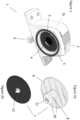
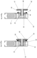
- Figure 1 shows a front perspective view of a female connector 1 provided in accordance with a preferred embodiment of the invention.
- the female connector 1 shown is formed by a main body 2 which defines an interior cavity 2b (shown in figure 3 ) with a housing entrance 2c.
- a receiving element in the form of sleeve 3 in this example is located within the cavity 2b, the sleeve having smaller dimensions than that of the cavity 2b.
- the enlarged insert cross-section views of the female connector provided by figures 5 and 7 show this arrangement in more detail. These figures also illustrate features of the interior walls of a receiving cavity 4 defined by the sleeve 3.
- the inner dimensions of the interior cavity 2b perpendicular, or transverse, to the receiving cavity are greater than outer dimensions of the sleeve 3 perpendicular to the receiving cavity to allow movement of the sleeve 3 in directions perpendicular within the housing 2.
- the dimensions of the inner cavity 2b parallel with the receiving cavity and the outer dimensions of the sleeve parallel with the receiving cavity prevent substantial movement of the sleeve parallel to the receiving cavity 4 and retain the sleeve 3 in the housing 2.
- the housing aperture 2c is narrower than the width of the sleeve 3 to retain the sleeve in the housing. Therefore the sleeve 3 and receiving cavity 4 are supported against forces parallel to the receiving cavity while being able to move over an area in two dimensions under forces perpendicular to the receiving cavity 4.
- the housing entrance 2c has an area which corresponds to the area covered by the entrance 4b of the receiving cavity 4 as the sleeve 3 is moved over area of movement allowed by the inner dimensions of the cavity and outer dimensions of the sleeve. This allow the entrance of the receiving cavity to be exposed through the housing cavity 2c wherever the sleeve 4 is located in the area of movement allowed.
- housing cavity 2 is cylindrical and the housing cavity entrance 2c is circular.
- the perimeter of the entrance to the receiving cavity is surrounded by a gripping surface, formed in this embodiment by a flexible resilient rubber O-ring 5.
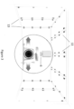
- the female connector incorporates a friction lock assembly as shown with respect to figure 1 and the enlarged insert cross-section end view of the female connector provided by figures 3 .
- the frictional assembly is provided by a centrally positioned T-shaped projection 6 extending from the surface of the female connector which is to engage with a channel formed in the support framework shown with respect to figure 3.
- Figure 3 also illustrates how variations in the orientation of the female connector will engage and disengage the T-projection of the friction lock assembly.
- Figure 2a shows a front perspective view a male connector 7 provided in accordance with the embodiment shown with respect to figure 1.
- Figure 2b shows a rear perspective view of the same male connector.
- the male connector 7 defines an engagement projection 8 which extends from a locking surface 9.
- the o-ring 5 and locking surface 9 provide cooperating engagement surfaces which are able to engage each other to prevent movement of the male component relative to the housing 2 of the female component and perpendicular to the engagement projection.
- the engagement projection 8 has a substantially perpendicular orientation to the plane of the locking surface 9.
- the locking surface includes a number of projecting ridges 10 which extend substantially across the width of the locking surface.
- a cooperating gripping surface on the female part 1 cooperates with the locking surface 8 when the locking surface 9 is brought into engagement with the female connector 1.
- the gripping surface is provided by an O-ring 5 set into a surface of the housing 2 of the female connector 1 which extends substantially parallel to the locking surface 9 of a male connector 7 when projection 8 is received in the receiving cavity 4.
- the ridges co-operate with the rubber O-ring 5 provided on the female connector to lock these two components engage to prevent movement in the plane of the locking surface when the locking surface 9 and female part are brought together, as shown in more detail with respect to figure 7 .
- the locking surface 9 locks the position of the male connector 7 relative to the female connector 1 in the plane of the locking surface 8 when the locking surface 8 engages a gripping surface 5 of the female part.
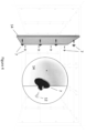
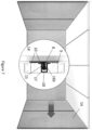
- Figure 3 shows a view of multiple female connectors provided in accordance with the embodiment of figure 1 which have been engaged with a support framework 13 installed within the interior walls and ceiling of a structure.
- Figure 4 also illustrates the attachment of multiple male connectors provided in accordance the embodiment of figures 2a, 2b to the interior side of surface panel 14.
- the male and female connectors are matched in pairs and deployed in a complimentary pattern.
- the male connectors are screwed into the interior side of each panel 14, while the female connectors are slid along channels formed in the beams of the framework 13 and locked in place when they have a complimentary alignment.
- the configuration of the connector assembly shown in Figure 5 provides initial positioning of the panels used to form the walls of the structure as shown with respect to figure 3 using the male and female connectors of figures 1 and 2a, 2b .
- the male projection 8 of the male connector 7 and the receiving cavity 4 are cooperatively engaged with the male projection held in a first, positioning zone 15. Specifically, the male projection 8 is received in the cavity 4 with a length of the projection 8 extending from the cavity 4 through the housing cavity 2b and extending away from the female connector to hold the locking surface 9 out of engagement with the O-ring 5 of the female connector.
- the cooperative engagement of the receiving cavity 4 and projection 8 secures the male connector 7 to the sleeve 3 which is retained in the housing 2 so the male connector 7 is secured to the female connector.
- the sleeve 4 is able to move within the housing cavity 2 to allow the position secured male connector 7 to be adjusted within an area lying in the plane perpendicular to the receiving cavity 4 and projection 8.
- the interior side of the panel 14 is bought into close proximity with the framework 13 and the male and female connector pairs are aligned with one another.
- the ends 8a of the engagement projections 8 are inserted through the entrance of the female connector's receiving cavities. This action locates the ends of the engagement projections 8 within a first positioning zone 15 defined, in this example, by a pair of projections 16a, 16b formed in the interior walls of the receiving cavity.
- the end of the engagement projection 8 has an increased diameter when compared to the rest of its length. This section is therefore easily trapped and contained within the first positioning zone 15.
- Figure 7 illustrates the locking of each of the panels of figures 5 and 6 to the support framework shown with respect to figure 3 .
- the panel 14 can be urged further inwards towards the support frame 13 to drive the end of the engagement projection 8 into a second locking zone 17 of the receiving cavity 4.
- the second locking zone 17 is bounded at one end by the end wall 18 of the cavity and at the opposite end by one of the projections 16b also used to form the positioning zone.
- this interior cavity incorporates a number of ribs 30 which extend towards the sleeve when located within the interior cavity 24. These ribs locate the sleeve while still allowing a degree of movement relative to the main body of the female connector.
- the female connector also incorporates a friction lock assembly similar to that illustrated with respect to the embodiment of figures 1-7 .
- the "T" projection 26 used to form this component is deployed at one end of the main body of the female connector.
- Figure 9a shows the initial positioning phase of a panel installation process when the female connector of figure 8a is used with a complimentary male connector. Again the male and female connector pairs are aligned with one another and the end of the male's engagement projection 28 is inserted through the entrance of the female connector's receiving cavity. This action moves the end of the engagement projection through a positioning zone 31 and into a locking zone 32 defined by the sleeve 23 used to form the female connector's receiving cavity. The portion 33 of the shaft of the engagement projection adjacent to its end which has a restricted girth is captured in the positioning zone 31 by contact with the projecting portions 34 of interior wall of the receiving cavity. A second region 35 of the engagement projection with an increased diameter blocks further motion of the engagement projection 28 into the receiving cavity.
- the housing entrance 2c may define an area that outside the range of movement allowed for the receiving cavity entrance 4b, for example to allow space for a guide recess suitable to guide an end of a projection of a male part 7 to the receiving cavity entrance 4b.
- the sleeve may be biased towards a central position within the housing cavity to facilitate the projection of the male connector being received by the receiving cavity of the sleeve.
- the sleeve may have biasing elements.
- the female connector may have a biasing element provided.
- the sleeve may have surface features which cause the head of the projection of the male connector to move the sleeve towards alignment with the projection.
- the locking surface is located on the female component and the gripping surface is located on the male connector.
- cooperating surfaces are located on the female connector and male connector to engage and lock when they are forced together.
- cooperating surfaces have spikes, abrasive elements, complementary gripping elements or other elements known to the reader as suitable to engage to lock the connectors against movement over each other.
- the receiving cavity and gripping and/or locking surface is provided by a unitary component.
- the component defines the gripping and/or locking surface and the receiving cavity and a part connecting the surface and cavity.
- Embodiments of the present invention provide a connection system with a projection on a first connector and a co-operating cavity on a second connector to provide push-through connection of the connectors in first and second configurations in which the projection extends to first and second depths respectively within the cavity, wherein one or more of the projection or cavity is movable in two dimensions perpendicular to a longitudinal axis of the projection when received in the cavity, wherein the first and second connectors have cooperating locking surfaces arranged to engage each other when the projection is received at the second depth to prevent said movement in two dimensions and wherein the cooperating locking surfaces do not engage each other so as to prevent said movement in two dimensions when the projection is received at the first depth in the receiving cavity.
- first engagement surface is a resilient gripping surface and the second engagement surface is one or more protrusions.
- an engagement surface may comprise any surface on the main body of the female connector or any cooperating surface on the male connector where cooperating surfaces have features of shape, contour, resilience or friction known as suitable to the skilled person to engage for given applications.
- Embodiments of the present invention may provide many potential advantages over the prior art.
- the present invention may provide a connection system which allows a connector, such as a female connector, to be secured to a cooperating connector, such as a male connector, and subsequently adjusted in relative position and locked in position.
- Embodiments of the present invention may provide a connection system which allows a relatively unskilled installer to engage a surface panel with a support framework quickly and using a limited number of tools.
- the invention may utilise extruded material frameworks where connectors are engaged with a channel formed in such extrusions. Connectors may be readily engaged in position along the length of such channels to position a surface panel as desired.
- Embodiments of the invention may provide flexibility in the positioning of a panel once initially engaged with a support frame.
- Panels may be initially supported on a framework in a positioning configuration, which preferably allows the position of the panel to be adjusted in two dimensions parallel to the surface of the structure being formed. Once correctly positioned the invention then allows the panel to be locked in place, and can also allow panels to be readily detached from the support frame if desired.
- a channel of a beam may be substitutes for a rail or other feature known to the skilled person as able to be engaged by a connector.
Landscapes
- Engineering & Computer Science (AREA)
- Architecture (AREA)
- General Engineering & Computer Science (AREA)
- Civil Engineering (AREA)
- Structural Engineering (AREA)
- Mechanical Engineering (AREA)
- Connector Housings Or Holding Contact Members (AREA)
- Details Of Connecting Devices For Male And Female Coupling (AREA)
Applications Claiming Priority (3)
| Application Number | Priority Date | Filing Date | Title |
|---|---|---|---|
| NZ73974518 | 2018-02-08 | ||
| AU2018904195A AU2018904195A0 (en) | 2018-11-05 | A Surface Panel Connection System | |
| PCT/NZ2019/050012 WO2019156576A1 (en) | 2018-02-08 | 2019-02-08 | A surface panel connection system |
Publications (4)
| Publication Number | Publication Date |
|---|---|
| EP3749865A1 EP3749865A1 (en) | 2020-12-16 |
| EP3749865A4 EP3749865A4 (en) | 2021-11-10 |
| EP3749865B1 true EP3749865B1 (en) | 2025-07-02 |
| EP3749865C0 EP3749865C0 (en) | 2025-07-02 |
Family
ID=67549004
Family Applications (1)
| Application Number | Title | Priority Date | Filing Date |
|---|---|---|---|
| EP19751977.0A Active EP3749865B1 (en) | 2018-02-08 | 2019-02-08 | A surface panel connection system |
Country Status (9)
| Country | Link |
|---|---|
| US (2) | US10982698B2 (pl) |
| EP (1) | EP3749865B1 (pl) |
| CN (1) | CN112055788B (pl) |
| AU (2) | AU2019217218B2 (pl) |
| CA (1) | CA3090651A1 (pl) |
| ES (1) | ES3036902T3 (pl) |
| NZ (1) | NZ767698A (pl) |
| PL (1) | PL3749865T3 (pl) |
| WO (1) | WO2019156576A1 (pl) |
Families Citing this family (1)
| Publication number | Priority date | Publication date | Assignee | Title |
|---|---|---|---|---|
| AU2024229875A1 (en) * | 2023-03-02 | 2025-10-02 | XFrame Ltd. | Fastener clip and method for use thereof in attaching building components together |
Citations (2)
| Publication number | Priority date | Publication date | Assignee | Title |
|---|---|---|---|---|
| US20120240363A1 (en) * | 2011-03-24 | 2012-09-27 | Yun Shin Lee | Two Stage Serviceable Safety Clip |
| WO2013126851A1 (en) * | 2012-02-24 | 2013-08-29 | Ykk Corporation | Fastener, fastening system and method of securing using fastening system |
Family Cites Families (42)
| Publication number | Priority date | Publication date | Assignee | Title |
|---|---|---|---|---|
| US1548586A (en) * | 1924-10-07 | 1925-08-04 | Edkins William John | Snap fastener |
| US1723621A (en) * | 1928-06-30 | 1929-08-06 | Vitreous Steel Products Compan | Wall structure |
| US1854772A (en) * | 1930-02-24 | 1932-04-19 | Stuken Hubert | Wall tile covering |
| US2395726A (en) * | 1944-11-08 | 1946-02-26 | Tufo Nicholas A Del | Paneling structure |
| US2946612A (en) * | 1958-02-24 | 1960-07-26 | Amerock Corp | Self-alining catch |
| US3182367A (en) * | 1961-12-11 | 1965-05-11 | Bishop & Babcock Corp | Fastener |
| US3393599A (en) * | 1966-08-17 | 1968-07-23 | Illinois Tool Works | Fastening device |
| JPS5325094Y2 (pl) * | 1975-12-09 | 1978-06-27 | ||
| US4253226A (en) * | 1979-07-25 | 1981-03-03 | Tadashi Takeda | Method for mounting up a plastic fastener |
| DE9205186U1 (de) * | 1992-04-14 | 1992-06-17 | Emhart Inc., Newark, Del. | Druckknopf |
| JP2577276Y2 (ja) * | 1992-06-10 | 1998-07-23 | 株式会社ニフコ | マット状物の止め具 |
| DE19517010C2 (de) * | 1995-05-10 | 1998-03-19 | Prym William Gmbh & Co Kg | Druckknopfverschluß |
| NL1005401C2 (nl) * | 1997-02-28 | 1998-08-31 | Tom Ronald Offers | Montagesysteem ter bevestiging van tegels. |
| DE10153858C2 (de) * | 2001-10-25 | 2003-10-02 | Joachim Fischbach | Vorrichtung zur lösbaren Befestigung von wenigstens einem Flächenelement, ein System mit mehreren solcher Vorrichtungen und deren Verwendung |
| FR2832746A1 (fr) * | 2001-11-28 | 2003-05-30 | Atelier Interior | Systeme de serrage - fixation pour parements de cloisons amovibles |
| DE10209240C1 (de) * | 2002-03-04 | 2003-04-10 | Daimler Chrysler Ag | Sitzkissen mit Verriegelung |
| ITTO20020307A1 (it) | 2002-04-09 | 2003-10-09 | Legrand Spa | Bullone con testa a t. |
| US7320571B2 (en) * | 2002-08-01 | 2008-01-22 | Newfrey Llc | Device for mounting a component such as a pipe on a stud |
| US7082919B2 (en) * | 2003-03-28 | 2006-08-01 | Toyoda Gosei Co., Ltd. | Mounting structure for engine cover |
| US20050008456A1 (en) * | 2003-06-18 | 2005-01-13 | Ejot Gmbh & Co. Kg | Device for securing a structural element to a panel-like component |
| JP4850573B2 (ja) * | 2006-04-24 | 2012-01-11 | ポップリベット・ファスナー株式会社 | アンダーカバー等の固定具及び取付装置 |
| DE102006038991A1 (de) * | 2006-08-21 | 2008-02-28 | Newfrey Llc, Newark | Clip aus Kunststoff zur Befestigung eines Gegenstands an einem Bolzen |
| US20090026673A1 (en) * | 2007-07-23 | 2009-01-29 | Clark Sylvester S | Vibration-dampening clip assembly |
| US8328488B2 (en) * | 2007-07-23 | 2012-12-11 | Illinois Tool Works Inc. | Stud retainer apparatus |
| WO2010002280A1 (en) * | 2008-07-03 | 2010-01-07 | Fastmount Limited | Panel mounting clip with adhesives |
| BRPI0918574A2 (pt) * | 2008-08-22 | 2018-05-22 | Mcclure Travis | inserção dinâmica de luva para uso com um sistema cego de fixação |
| CN102257580B (zh) * | 2008-12-19 | 2012-12-12 | 丰田自动车株式会社 | 护孔环 |
| GB2472654A (en) | 2009-08-15 | 2011-02-16 | Bentley Motors Ltd | A retention system |
| DE112010000443B4 (de) * | 2009-10-27 | 2014-10-23 | Tokai Chemical Industries Ltd. | Schallschutzabdeckung sowie Herstellungsverfahren einer solchen |
| DE202010008192U1 (de) * | 2010-07-30 | 2010-10-07 | Newfrey Llc, Newark | Befestigungselement und Befestigungsanordnung mit einem Befestigungselement |
| JP6073610B2 (ja) * | 2012-09-11 | 2017-02-01 | 住友理工株式会社 | エンジンカバー |
| DE202012009468U1 (de) * | 2012-10-04 | 2012-10-23 | Fairchild Fasteners Europe - Camloc Gmbh | Verschlussbolzen und Verschlusselement hiermit |
| US9644667B2 (en) * | 2012-10-18 | 2017-05-09 | Apple Inc. | Floating fasteners |
| JP6436282B2 (ja) * | 2013-04-23 | 2018-12-12 | ファストマウント リミテッドFastmount Limited | コネクタ組立体およびコネクタ組立体用の部品のキット |
| CN103204302B (zh) * | 2013-04-24 | 2015-07-22 | 广东华恒盛重包装集团有限公司 | 一种子母扣件 |
| KR101562628B1 (ko) * | 2013-11-16 | 2015-10-22 | 주식회사 이지아이비스 | 점형 열교를 차단하고 마감재 부착이 용이한 단열패널 고정용 연결유닛, 이를 이용한 외단열 시스템 및 그 시공방법 |
| KR20150081517A (ko) * | 2014-01-06 | 2015-07-15 | 정용주 | 외벽공사 중 오픈조인트방식을 적용한 유니트공법 중 차수막을 형성하는 방법 |
| CN203977786U (zh) | 2014-06-30 | 2014-12-03 | 索菲亚家居股份有限公司 | 一种墙板快速拼装装置 |
| DE202015005870U1 (de) * | 2015-08-25 | 2016-11-28 | Böllhoff Verbindungstechnik GmbH | Zweiteilige Steckkupplung zur Verbindung von Bauteilen |
| US20180023759A1 (en) * | 2016-03-30 | 2018-01-25 | 3 T Assets, LLC | Assembly Including a Mounting Portion and an Implement-Retaining Portion |
| DE102016113022A1 (de) * | 2016-07-14 | 2018-01-18 | Benteler Automobiltechnik Gmbh | Verbindungsanordnung mit zwei Verbindungsteilen |
| DE102018200021A1 (de) * | 2018-01-02 | 2019-07-04 | Volkswagen Aktiengesellschaft | Befestigungsanordnung zur lösbaren Befestigung eines Anbauteils an einer Tragstruktur |
-
2019
- 2019-02-08 EP EP19751977.0A patent/EP3749865B1/en active Active
- 2019-02-08 WO PCT/NZ2019/050012 patent/WO2019156576A1/en not_active Ceased
- 2019-02-08 AU AU2019217218A patent/AU2019217218B2/en active Active
- 2019-02-08 CN CN201980016511.3A patent/CN112055788B/zh active Active
- 2019-02-08 ES ES19751977T patent/ES3036902T3/es active Active
- 2019-02-08 CA CA3090651A patent/CA3090651A1/en not_active Abandoned
- 2019-02-08 PL PL19751977.0T patent/PL3749865T3/pl unknown
- 2019-02-08 US US16/644,119 patent/US10982698B2/en active Active
- 2019-02-08 NZ NZ767698A patent/NZ767698A/en unknown
-
2021
- 2021-03-30 US US17/216,873 patent/US11946505B2/en active Active
- 2021-09-13 AU AU2021232656A patent/AU2021232656A1/en not_active Abandoned
Patent Citations (2)
| Publication number | Priority date | Publication date | Assignee | Title |
|---|---|---|---|---|
| US20120240363A1 (en) * | 2011-03-24 | 2012-09-27 | Yun Shin Lee | Two Stage Serviceable Safety Clip |
| WO2013126851A1 (en) * | 2012-02-24 | 2013-08-29 | Ykk Corporation | Fastener, fastening system and method of securing using fastening system |
Also Published As
| Publication number | Publication date |
|---|---|
| ES3036902T3 (en) | 2025-09-25 |
| US11946505B2 (en) | 2024-04-02 |
| US20210215179A1 (en) | 2021-07-15 |
| EP3749865A4 (en) | 2021-11-10 |
| US10982698B2 (en) | 2021-04-20 |
| AU2021232656A1 (en) | 2021-10-21 |
| AU2019217218B2 (en) | 2021-09-30 |
| AU2019217218A1 (en) | 2020-10-01 |
| EP3749865C0 (en) | 2025-07-02 |
| NZ767698A (en) | 2022-09-30 |
| CA3090651A1 (en) | 2019-08-15 |
| PL3749865T3 (pl) | 2026-03-02 |
| CN112055788A (zh) | 2020-12-08 |
| WO2019156576A1 (en) | 2019-08-15 |
| CN112055788B (zh) | 2022-07-12 |
| US20200271148A1 (en) | 2020-08-27 |
| EP3749865A1 (en) | 2020-12-16 |
Similar Documents
| Publication | Publication Date | Title |
|---|---|---|
| US6484979B1 (en) | Adjustable electrical box support | |
| US6484980B2 (en) | Field bendable tab for electrical box support | |
| EP1985771A1 (en) | Wall framing system | |
| EP3245412B1 (en) | Retainer assembly | |
| US9540804B1 (en) | Cladding attachment system | |
| CA2418547C (en) | Stiffener construction having a snap-on connector, for use with a wall panel shell in a wall system | |
| KR20020096935A (ko) | 벽 기둥을 지지하기 위한 트랙 배치 및 벽 골조 조립물 및조립 방법 | |
| EP3464758B1 (en) | Panel systems and components | |
| US9932740B2 (en) | Cladding tie | |
| US11168477B1 (en) | Apparatus and method for hanging architectural panels with concealed attachment points | |
| CN116981818A (zh) | 带有机械锁定系统的建筑镶板 | |
| EP3749865B1 (en) | A surface panel connection system | |
| US8177195B2 (en) | Connector components and methods of use | |
| US4617772A (en) | Wall panel joiner | |
| US20170370388A1 (en) | Apparatuses for mounting fixtures to a substrate, and related methods | |
| EP4236726B1 (en) | Shelf system comprising a marble shelf | |
| US10597877B2 (en) | Fitting for laying decking boards | |
| EP4165256B1 (en) | Anchoring device and system for panels and similar roofings | |
| CN211666050U (zh) | 装配式吊顶收口结构以及包括其的吊顶 | |
| CA2515500A1 (en) | Hide-a-nail | |
| US20210317667A1 (en) | Façade system | |
| AU701269B2 (en) | Fixing clip | |
| JPH0635496U (ja) | 外装化粧材の固定構造 | |
| AU2017254901A1 (en) | Assembly for cladding a surface | |
| JPH09228594A (ja) | 竪樋の取付構造 |
Legal Events
| Date | Code | Title | Description |
|---|---|---|---|
| STAA | Information on the status of an ep patent application or granted ep patent |
Free format text: STATUS: THE INTERNATIONAL PUBLICATION HAS BEEN MADE |
|
| PUAI | Public reference made under article 153(3) epc to a published international application that has entered the european phase |
Free format text: ORIGINAL CODE: 0009012 |
|
| STAA | Information on the status of an ep patent application or granted ep patent |
Free format text: STATUS: REQUEST FOR EXAMINATION WAS MADE |
|
| 17P | Request for examination filed |
Effective date: 20200907 |
|
| AK | Designated contracting states |
Kind code of ref document: A1 Designated state(s): AL AT BE BG CH CY CZ DE DK EE ES FI FR GB GR HR HU IE IS IT LI LT LU LV MC MK MT NL NO PL PT RO RS SE SI SK SM TR |
|
| AX | Request for extension of the european patent |
Extension state: BA ME |
|
| DAV | Request for validation of the european patent (deleted) | ||
| DAX | Request for extension of the european patent (deleted) | ||
| A4 | Supplementary search report drawn up and despatched |
Effective date: 20211013 |
|
| RIC1 | Information provided on ipc code assigned before grant |
Ipc: E04F 13/24 20060101ALI20211007BHEP Ipc: F16B 21/07 20060101ALI20211007BHEP Ipc: F16B 5/06 20060101AFI20211007BHEP |
|
| STAA | Information on the status of an ep patent application or granted ep patent |
Free format text: STATUS: EXAMINATION IS IN PROGRESS |
|
| 17Q | First examination report despatched |
Effective date: 20240220 |
|
| RAP3 | Party data changed (applicant data changed or rights of an application transferred) |
Owner name: FASTMOUNT LIMITED |
|
| GRAP | Despatch of communication of intention to grant a patent |
Free format text: ORIGINAL CODE: EPIDOSNIGR1 |
|
| STAA | Information on the status of an ep patent application or granted ep patent |
Free format text: STATUS: GRANT OF PATENT IS INTENDED |
|
| INTG | Intention to grant announced |
Effective date: 20250127 |
|
| GRAS | Grant fee paid |
Free format text: ORIGINAL CODE: EPIDOSNIGR3 |
|
| GRAA | (expected) grant |
Free format text: ORIGINAL CODE: 0009210 |
|
| STAA | Information on the status of an ep patent application or granted ep patent |
Free format text: STATUS: THE PATENT HAS BEEN GRANTED |
|
| AK | Designated contracting states |
Kind code of ref document: B1 Designated state(s): AL AT BE BG CH CY CZ DE DK EE ES FI FR GB GR HR HU IE IS IT LI LT LU LV MC MK MT NL NO PL PT RO RS SE SI SK SM TR |
|
| REG | Reference to a national code |
Ref country code: GB Ref legal event code: FG4D |
|
| REG | Reference to a national code |
Ref country code: CH Ref legal event code: EP |
|
| REG | Reference to a national code |
Ref country code: DE Ref legal event code: R096 Ref document number: 602019071943 Country of ref document: DE |
|
| REG | Reference to a national code |
Ref country code: IE Ref legal event code: FG4D |
|
| U01 | Request for unitary effect filed |
Effective date: 20250729 |
|
| U07 | Unitary effect registered |
Designated state(s): AT BE BG DE DK EE FI FR IT LT LU LV MT NL PT RO SE SI Effective date: 20250804 |
|
| REG | Reference to a national code |
Ref country code: ES Ref legal event code: FG2A Ref document number: 3036902 Country of ref document: ES Kind code of ref document: T3 Effective date: 20250925 |
|
| PG25 | Lapsed in a contracting state [announced via postgrant information from national office to epo] |
Ref country code: IS Free format text: LAPSE BECAUSE OF FAILURE TO SUBMIT A TRANSLATION OF THE DESCRIPTION OR TO PAY THE FEE WITHIN THE PRESCRIBED TIME-LIMIT Effective date: 20251102 |
|
| PG25 | Lapsed in a contracting state [announced via postgrant information from national office to epo] |
Ref country code: NO Free format text: LAPSE BECAUSE OF FAILURE TO SUBMIT A TRANSLATION OF THE DESCRIPTION OR TO PAY THE FEE WITHIN THE PRESCRIBED TIME-LIMIT Effective date: 20251002 |
|
| PG25 | Lapsed in a contracting state [announced via postgrant information from national office to epo] |
Ref country code: HR Free format text: LAPSE BECAUSE OF FAILURE TO SUBMIT A TRANSLATION OF THE DESCRIPTION OR TO PAY THE FEE WITHIN THE PRESCRIBED TIME-LIMIT Effective date: 20250702 |
|
| PG25 | Lapsed in a contracting state [announced via postgrant information from national office to epo] |
Ref country code: GR Free format text: LAPSE BECAUSE OF FAILURE TO SUBMIT A TRANSLATION OF THE DESCRIPTION OR TO PAY THE FEE WITHIN THE PRESCRIBED TIME-LIMIT Effective date: 20251003 |
|
| PG25 | Lapsed in a contracting state [announced via postgrant information from national office to epo] |
Ref country code: CZ Free format text: LAPSE BECAUSE OF FAILURE TO SUBMIT A TRANSLATION OF THE DESCRIPTION OR TO PAY THE FEE WITHIN THE PRESCRIBED TIME-LIMIT Effective date: 20250702 |
|
| PG25 | Lapsed in a contracting state [announced via postgrant information from national office to epo] |
Ref country code: RS Free format text: LAPSE BECAUSE OF FAILURE TO SUBMIT A TRANSLATION OF THE DESCRIPTION OR TO PAY THE FEE WITHIN THE PRESCRIBED TIME-LIMIT Effective date: 20251002 |
|
| U20 | Renewal fee for the european patent with unitary effect paid |
Year of fee payment: 8 Effective date: 20260213 |
|
| PG25 | Lapsed in a contracting state [announced via postgrant information from national office to epo] |
Ref country code: SM Free format text: LAPSE BECAUSE OF FAILURE TO SUBMIT A TRANSLATION OF THE DESCRIPTION OR TO PAY THE FEE WITHIN THE PRESCRIBED TIME-LIMIT Effective date: 20250702 |
|
| PGFP | Annual fee paid to national office [announced via postgrant information from national office to epo] |
Ref country code: GB Payment date: 20260213 Year of fee payment: 8 |
|
| PGFP | Annual fee paid to national office [announced via postgrant information from national office to epo] |
Ref country code: IE Payment date: 20260206 Year of fee payment: 8 |
|
| PGFP | Annual fee paid to national office [announced via postgrant information from national office to epo] |
Ref country code: TR Payment date: 20260109 Year of fee payment: 8 |