EP3748244A2 - Klimaanlage - Google Patents
Klimaanlage Download PDFInfo
- Publication number
- EP3748244A2 EP3748244A2 EP20173895.2A EP20173895A EP3748244A2 EP 3748244 A2 EP3748244 A2 EP 3748244A2 EP 20173895 A EP20173895 A EP 20173895A EP 3748244 A2 EP3748244 A2 EP 3748244A2
- Authority
- EP
- European Patent Office
- Prior art keywords
- detection sensor
- refrigerant detection
- refrigerant
- control section
- air
- Prior art date
- Legal status (The legal status is an assumption and is not a legal conclusion. Google has not performed a legal analysis and makes no representation as to the accuracy of the status listed.)
- Withdrawn
Links
- 239000003507 refrigerant Substances 0.000 claims abstract description 238
- 238000001514 detection method Methods 0.000 claims abstract description 166
- 230000005856 abnormality Effects 0.000 claims abstract description 43
- 238000004378 air conditioning Methods 0.000 claims description 10
- 238000012545 processing Methods 0.000 description 35
- 238000009434 installation Methods 0.000 description 13
- 230000002159 abnormal effect Effects 0.000 description 8
- 238000000034 method Methods 0.000 description 6
- 230000005540 biological transmission Effects 0.000 description 4
- 238000004891 communication Methods 0.000 description 4
- 238000010586 diagram Methods 0.000 description 4
- 238000012546 transfer Methods 0.000 description 4
- 238000001816 cooling Methods 0.000 description 3
- 230000000694 effects Effects 0.000 description 3
- 238000010438 heat treatment Methods 0.000 description 3
- 230000007246 mechanism Effects 0.000 description 2
- 230000004044 response Effects 0.000 description 2
- 239000007787 solid Substances 0.000 description 2
- 238000002485 combustion reaction Methods 0.000 description 1
- 238000004519 manufacturing process Methods 0.000 description 1
- 238000012986 modification Methods 0.000 description 1
- 230000004048 modification Effects 0.000 description 1
- 230000000149 penetrating effect Effects 0.000 description 1
- 239000004065 semiconductor Substances 0.000 description 1
- 230000035945 sensitivity Effects 0.000 description 1
- XLYOFNOQVPJJNP-UHFFFAOYSA-N water Substances O XLYOFNOQVPJJNP-UHFFFAOYSA-N 0.000 description 1
Images



Classifications
-
- F—MECHANICAL ENGINEERING; LIGHTING; HEATING; WEAPONS; BLASTING
- F24—HEATING; RANGES; VENTILATING
- F24F—AIR-CONDITIONING; AIR-HUMIDIFICATION; VENTILATION; USE OF AIR CURRENTS FOR SCREENING
- F24F11/00—Control or safety arrangements
- F24F11/30—Control or safety arrangements for purposes related to the operation of the system, e.g. for safety or monitoring
- F24F11/32—Responding to malfunctions or emergencies
-
- F—MECHANICAL ENGINEERING; LIGHTING; HEATING; WEAPONS; BLASTING
- F24—HEATING; RANGES; VENTILATING
- F24F—AIR-CONDITIONING; AIR-HUMIDIFICATION; VENTILATION; USE OF AIR CURRENTS FOR SCREENING
- F24F1/00—Room units for air-conditioning, e.g. separate or self-contained units or units receiving primary air from a central station
- F24F1/0003—Room units for air-conditioning, e.g. separate or self-contained units or units receiving primary air from a central station characterised by a split arrangement, wherein parts of the air-conditioning system, e.g. evaporator and condenser, are in separately located units
-
- F—MECHANICAL ENGINEERING; LIGHTING; HEATING; WEAPONS; BLASTING
- F24—HEATING; RANGES; VENTILATING
- F24F—AIR-CONDITIONING; AIR-HUMIDIFICATION; VENTILATION; USE OF AIR CURRENTS FOR SCREENING
- F24F11/00—Control or safety arrangements
- F24F11/30—Control or safety arrangements for purposes related to the operation of the system, e.g. for safety or monitoring
- F24F11/32—Responding to malfunctions or emergencies
- F24F11/36—Responding to malfunctions or emergencies to leakage of heat-exchange fluid
-
- F—MECHANICAL ENGINEERING; LIGHTING; HEATING; WEAPONS; BLASTING
- F24—HEATING; RANGES; VENTILATING
- F24F—AIR-CONDITIONING; AIR-HUMIDIFICATION; VENTILATION; USE OF AIR CURRENTS FOR SCREENING
- F24F11/00—Control or safety arrangements
- F24F11/89—Arrangement or mounting of control or safety devices
-
- F—MECHANICAL ENGINEERING; LIGHTING; HEATING; WEAPONS; BLASTING
- F25—REFRIGERATION OR COOLING; COMBINED HEATING AND REFRIGERATION SYSTEMS; HEAT PUMP SYSTEMS; MANUFACTURE OR STORAGE OF ICE; LIQUEFACTION SOLIDIFICATION OF GASES
- F25B—REFRIGERATION MACHINES, PLANTS OR SYSTEMS; COMBINED HEATING AND REFRIGERATION SYSTEMS; HEAT PUMP SYSTEMS
- F25B13/00—Compression machines, plants or systems, with reversible cycle
-
- F—MECHANICAL ENGINEERING; LIGHTING; HEATING; WEAPONS; BLASTING
- F25—REFRIGERATION OR COOLING; COMBINED HEATING AND REFRIGERATION SYSTEMS; HEAT PUMP SYSTEMS; MANUFACTURE OR STORAGE OF ICE; LIQUEFACTION SOLIDIFICATION OF GASES
- F25B—REFRIGERATION MACHINES, PLANTS OR SYSTEMS; COMBINED HEATING AND REFRIGERATION SYSTEMS; HEAT PUMP SYSTEMS
- F25B49/00—Arrangement or mounting of control or safety devices
- F25B49/02—Arrangement or mounting of control or safety devices for compression type machines, plants or systems
-
- F—MECHANICAL ENGINEERING; LIGHTING; HEATING; WEAPONS; BLASTING
- F25—REFRIGERATION OR COOLING; COMBINED HEATING AND REFRIGERATION SYSTEMS; HEAT PUMP SYSTEMS; MANUFACTURE OR STORAGE OF ICE; LIQUEFACTION SOLIDIFICATION OF GASES
- F25B—REFRIGERATION MACHINES, PLANTS OR SYSTEMS; COMBINED HEATING AND REFRIGERATION SYSTEMS; HEAT PUMP SYSTEMS
- F25B2500/00—Problems to be solved
- F25B2500/22—Preventing, detecting or repairing leaks of refrigeration fluids
- F25B2500/222—Detecting refrigerant leaks
Definitions
- One aspect of the present invention relates to an air-conditioner.
- JP-A-2019-60556 has been known as the technique of sensing refrigerant leakage from a refrigerant circuit. That is, JP-A-2019- 60556 describes a heat source device including at least one refrigerant sensor arranged in an indoor space in which each heat source unit is installed.
- An air-conditioner including: a switching section configured to switch a setting by manual operation; and a control section configured to report an abnormality by a reporting means in a case where a refrigerant detection sensor is not electrically connected to the control section in a state in which the setting of the switching section has been switched to a setting that the refrigerant detection sensor is installed.
- a refrigerant detection sensor (the refrigerant sensor) is not limited to one installed in a single uniform way regardless of the amount and/or type of refrigerant sealed in the refrigerant circuit.
- the refrigerant detection sensor is an optional component installed as necessary. In this case, a worker installs the refrigerant detection sensor upon installation of an air-conditioner. For this reason, there is a probability that failure to attach the refrigerant detection sensor and erroneous connection of the refrigerant detection sensor by the worker are caused.
- the refrigerant detection sensor (the refrigerant sensor) is the optional component in the technique described in JP-A-2019-60556 , it is difficult to correctly sense, e.g., failure to attach the refrigerant detection sensor only based on the presence or absence of connection of the refrigerant detection sensor.
- the absence of the refrigerant detection sensor is not actually included in, e.g., failure to attach the refrigerant detection sensor.
- an air-conditioner configured to properly report an abnormality regarding, e.g., installation of the refrigerant detection sensor even in a case where the refrigerant detection sensor is the optional component has been demanded.
- one object of the present invention is to provide an air-conditioner configured to properly report an abnormality regarding, e.g., installation of a refrigerant detection sensor.
- an air-conditioner includes: a switching section configured to switch a setting by manual operation; and a control section configured to report an abnormality by a reporting means in a case where a refrigerant detection sensor is not electrically connected to the control section in a state in which the setting of the switching section has been switched to a setting that the refrigerant detection sensor is installed.
- an air-conditioner includes: a switching section configured to switch a setting by manual operation; and a control section configured to report an abnormality by a reporting means in a case where a refrigerant detection sensor is electrically connected to the control section in a state in which the setting of the switching section has been switched to a setting that the refrigerant detection sensor is not installed.
- the air-conditioner configured to properly report the abnormality regarding, e.g., installation of the refrigerant detection sensor can be provided.
- Fig. 1 is a configuration diagram of an air-conditioner 100 according to an embodiment.
- dashed arrows in Fig. 1 indicate the flow of refrigerant in air-cooling operation.
- the air-conditioner 100 is equipment configured to perform air-conditioning operation such as the air-heating operation or the air-cooling operation. As illustrated in Fig. 1 , the air-conditioner 100 includes a compressor 11, an outdoor heat exchanger 12, an outdoor fan 13, and an expansion valve 14. Moreover, the air-conditioner 100 includes, in addition to the above-described configurations, an indoor heat exchanger 15, an indoor fan 16, and a four-way valve 17.
- the compressor 11 is equipment configured to compress low-temperature low-pressure gas refrigerant to discharge high-temperature high-pressure gas refrigerant. As illustrated in Fig. 1 , the compressor 11 includes a compressor motor 11a as a drive source.
- the outdoor heat exchanger 12 is a heat exchanger configured to exchange heat between refrigerant flowing in a heat transfer pipe (not shown) of the heat exchanger and external air sent from the outdoor fan 13.
- the outdoor fan 13 is a fan configured to send the external air into the outdoor heat exchanger 12.
- the outdoor fan 13 includes an outdoor fan motor 13a as a drive source, and is arranged in the vicinity of the outdoor heat exchanger 12.
- the expansion valve 14 is a valve configured to depressurize refrigerant condensed by a "condenser” (one of the outdoor heat exchanger 12 or the indoor heat exchanger 15). Note that the refrigerant depressurized by the expansion valve 14 is guided to an "evaporator" (the other one of the outdoor heat exchanger 12 or the indoor heat exchanger 15).
- the indoor heat exchanger 15 is a heat exchanger configured to exchange heat between refrigerant flowing in a heat transfer pipe g (see Fig. 3 ) of the heat exchanger and indoor air (air in an air-conditioning target space) sent from the indoor fan 16.
- the indoor fan 16 is a fan configured to send the indoor air into the indoor heat exchanger 15.
- the indoor fan 16 has an indoor fan motor 16a (see Fig. 2 ) as a drive source, and is arranged in the vicinity of the indoor heat exchanger 15.
- the four-way valve 17 is a valve for switching a refrigerant flow path according to an operation mode of the air-conditioner 100. For example, in the air-cooling operation (see the dashed arrows in Fig. 1 ), in a refrigerant circuit Q, refrigerant sequentially circulates through the compressor 11, the outdoor heat exchanger 12 (the condenser), the expansion valve 14, and the indoor heat exchanger 15 (the evaporator).
- refrigerant sequentially circulates through the compressor 11, the indoor heat exchanger 15 (the condenser), the expansion valve 14, and the outdoor heat exchanger 12 (the evaporator).
- one of the “condenser” or the “evaporator” as described above is the outdoor heat exchanger 12 and the other one of the “condenser” or the “evaporator” is the indoor heat exchanger 15.
- the compressor 11, the outdoor heat exchanger 12, the outdoor fan 13, the expansion valve 14, and the four-way valve 17 are installed in an outdoor unit Uo.
- the indoor heat exchanger 15 and the indoor fan 16 are installed in an indoor unit Ui.
- Fig. 2 is a functional block diagram of the air-conditioner 100.
- the indoor unit Ui illustrated in Fig. 2 includes a remote controller transmission/reception section 21, an indoor temperature sensor 22, a refrigerant detection sensor 23, a DIP switch 24 (a switching section), a light emitting diode 25 (LED: reporting means). Further, the indoor unit Ui includes an indoor control circuit 31, the indoor fan motor 16a, a right-left wind deflector motor 26a, and an upper-lower wind deflector motor 27a.
- the remote controller transmission/reception section 21 is configured to exchange predetermined information with a remote controller 40 via, e.g., infrared communication.
- the indoor temperature sensor 22 is a sensor configured to detect a temperature in a room (the air-conditioning target space), and is arranged on an air suction side of the indoor unit Ui.
- the refrigerant detection sensor 23 is a sensor configured to sense refrigerant leakage from the refrigerant circuit Q (see Fig. 1 ), and is installed at a predetermined spot in the indoor unit Ui.
- the refrigerant detection sensor 23 is an optional component, and is installed as necessary based on the amount and/or type of refrigerant sealed in the refrigerant circuit Q.
- the refrigerant detection sensor 23 is installed in many cases.
- the refrigerant detection sensor 23 is not installed in some cases.
- the refrigerant detection sensor 23 is installed in the indoor unit Ui as illustrated in Fig. 2 , but the refrigerant detection sensor 23 is not an essential configuration and is not installed in the indoor unit Ui in some cases.
- the DIP switch 24 illustrated in Fig. 2 is a switch configured to switch a setting by manual operation according to whether or not the refrigerant detection sensor 23 is installed.
- the DIP switch 24 is mounted on an indoor control board P (see Fig. 5 ).
- a worker switches the setting of the DIP switch 24 by a worker's hand or a tool (e.g., a driver). Note that details of processing regarding the DIP switch 24 will be described later.
- Signals from the remote controller transmission/reception section 21, the indoor temperature sensor 22, the refrigerant detection sensor 23, and the DIP switch 24 illustrated in Fig. 2 are output to the indoor control circuit 31.
- the indoor control circuit 31 includes electronic circuits (all circuits are not shown) such as a central processing unit (CPU), a read only memory (ROM), a random access memory (RAM), and various interfaces. Moreover, in the indoor control circuit 31, the CPU reads a program stored in the ROM and loads the program into the RAM, thereby executing various types of processing.
- CPU central processing unit
- ROM read only memory
- RAM random access memory
- the indoor control circuit 31 includes a storage section 31a and an indoor control section 31b.
- the storage section 31a stores data from the remote controller transmission/reception section 21, the indoor temperature sensor 22, the refrigerant detection sensor 23, and the DIP switch 24.
- the indoor control section 31b controls the LED 25 described subsequently, the indoor fan motor 16a, the right-left wind deflector motor 26a, and the upper-lower wind deflector motor 27a.
- the LED 25 is configured to report an abnormality regarding connection of the refrigerant detection sensor 23, and for example, is installed on an upper surface of a housing of the indoor unit Ui. Note that a case where the indoor control section 31b flashes the LED 25 will be described later.
- the indoor fan motor 16a is the drive source of the indoor fan 16 (see Fig. 1 ).
- the right-left wind deflector motor 26a is a drive source for turning a right-left wind deflector (not shown) in a right-left direction.
- the upper-lower wind deflector motor 27a is a drive source for turning upper-lower wind deflectors 271, 272 (see Figs. 3 and 4 ) in an upper-lower direction. Note that the right-left wind deflector motor 26a and the like may be omitted as necessary.
- the outdoor unit Uo includes an outdoor temperature sensor 28 and an outdoor control circuit 32.
- the outdoor temperature sensor 28 is a sensor configured to detect an outdoor temperature, and is installed at a predetermined spot in the outdoor unit Uo (see Fig. 1 ). Note that although not shown in Fig. 3 , multiple sensors configured to detect, e.g., a suction temperature and a discharge temperature of the compressor 11 (see Fig. 1 ) are also installed in the outdoor unit Uo in addition to the outdoor temperature sensor 28. A detection value of each sensor including the outdoor temperature sensor 28 is output to the outdoor control circuit 32.
- the outdoor control circuit 32 includes electronic circuits (all circuits are not shown) such as a CPU, a ROM, a RAM, and various interfaces.
- the outdoor control circuit 32 is connected to the indoor control circuit 31 via a communication line.
- the outdoor control circuit 32 includes a storage section 32a and an outdoor control section 32b.
- the storage section 32a stores, e.g., data received from the indoor control circuit 31.
- the outdoor control section 32b controls, e.g., the compressor motor 11a, the outdoor fan motor 13a, the expansion valve 14, and the four-way valve 17.
- the indoor control circuit 31 and the outdoor control circuit 32 will be collectively referred to as a "control section 30.”
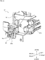
- Fig. 3 is a perspective view of the indoor unit Ui in a state in which a front panel and an electrical component box are detached.
- the indoor unit Ui illustrated in Fig. 3 the indoor unit Ui is partially disassembled and the refrigerant detection sensor 23 is moved laterally from an actual installation spot.
- a floor indoor unit Ui for domestic use is illustrated as one example in Fig. 3 .
- the present embodiment is also applicable to other types of air-conditioners 100.
- the indoor unit Ui includes a drain pan 18, a housing base 19, a stand 29, and the indoor control board P (a control board).
- the indoor heat exchanger 15 includes multiple fins f and the multiple heat transfer pipes g penetrating these fins f.
- the indoor fan 16 is, for example, a cylindrical cross-flow fan, and is arranged in the vicinity of the indoor heat exchanger 15.
- the drain pan 18 is a pan configured to receive condensed water from the indoor heat exchanger 15, and is arranged below the indoor heat exchanger 15.
- the housing base 19 is a housing in which, e.g., the indoor heat exchanger 15 and the indoor fan 16 are installed.
- the stand 29 is a table for installing the indoor unit Ui on the floor. Note that the stand 29 may be omitted and the indoor unit Ui may be installed on a wall in the room.
- the indoor control board P is a printed-circuit board on which the indoor control circuit 31 (i.e., a circuit component of the control section 30: see Fig. 2 ) is mounted and the DIP switch 24 (see Fig. 5 ) is also mounted. Note that in Fig. 3 , the indoor control board P is in an exposed state. The indoor control board P is actually housed in the electrical component box B (see Fig. 5 ).
- the refrigerant detection sensor 23 illustrated in Fig. 3 is the sensor configured to sense refrigerant leakage, and is provided in the vicinity of the drain pan 18. More specifically, the refrigerant detection sensor 23 is provided on one side of the drain pan 18 in a width direction (the right-left direction) of the indoor unit Ui, the drain pan 18 extending elongated in the width direction. Moreover, it is configured such that the refrigerant detection sensor 23 is housed in the front panel (not shown) and the housing base 19 of the indoor unit Ui. With this configuration, contact of a user's hand with the refrigerant detection sensor 23 can be reduced.
- Fig. 4 is a partially-enlarged view of a region K of Fig. 3 .
- the refrigerant detection sensor 23 includes a sensor board (not shown) on which a sensor element (not shown) is mounted, and a sensor case 23a configured to house the sensor board.
- the above-described sensor element is an element having sensitivity to a refrigerant concentration.
- An element such as a semiconductor element, an infrared element, a contact combustion element, or an electrochemical element can be used as such a sensor element.
- Multiple holes ha for taking refrigerant having leaked from the refrigerant circuit Q are provided at the sensor case 23a.
- a predetermined signal indicating refrigerant leakage is output from the refrigerant detection sensor 23 to the indoor control circuit 31 (see Fig. 2 ).
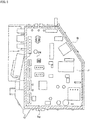
- Fig. 5 is a view for describing a component-mounting-side surface of the indoor control board P exposed after a lid of the electrical component box B has been detached.
- Fig. 5 illustrates, in a simplified manner, electronic components mounted on the indoor control board P.
- the electronic components mounted on the indoor control board P include the DIP switch 24 (also see Fig. 2 ) and a connector N.
- the DIP switch 24 is the switch configured to switch the setting by manual operation according to whether or not the refrigerant detection sensor 23 is installed.
- the DIP switch 24 is mounted on the indoor control board P.
- the DIP switch 24 and the connector N are mounted on the indoor control board P housed in the electrical component box B. Thus, e.g., erroneous switching of the DIP switch 24 by a user can be reduced.
- the worker detaches the lid (not shown) of the electrical component box B to expose the indoor control board P. Further, the worker switches the setting of the DIP switch 24 to such a setting (referred to as a "sensor present setting") that the refrigerant detection sensor 23 is installed. On the other hand, in the case of not installing the refrigerant detection sensor 23, the worker switches the setting of the DIP switch 24 to such a setting (referred to as a "sensor absent setting") that the refrigerant detection sensor 23 is not installed.
- the connector N illustrated in Fig. 5 is configured to electrically connect the refrigerant detection sensor 23 and the indoor control board P, and is mounted on the indoor control board P. Moreover, the worker inserts a predetermined connector (not shown) provided at a tip end of a wire of the refrigerant detection sensor 23 into the partner connector N mounted on the indoor control board P. Further, an opening hp through which the wire of the refrigerant detection sensor 23 is drawn is provided at the electrical component box B housed in the indoor unit Ui (see Fig. 3 ).
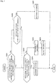
- Fig. 6 is a flowchart of the processing executed by the control section 30 of the air-conditioner 100 (see Figs. 2 and 5 , as necessary).
- the worker electrically connects, in advance of a series of processing illustrated in Fig. 6 , the wire of the refrigerant detection sensor 23 to the connector N on the indoor control board P (see Fig. 5 ) and switches the setting of the DIP switch 24 to the "sensor present setting.”
- Such a process is, upon installation of the air-conditioner 100, performed before power supply. Right after power supply, a series of processing illustrated in Fig. 6 is executed.
- connection of the refrigerant detection sensor 23 may be first performed by the worker before power supply, or switching of the setting of the DIP switch 24 may be first performed before power supply. This is because even when either of connection or switching is performed first, the same result is obtained if a state upon power supply is the same between connection and switching.
- the control section 30 determines whether or not the setting of the DIP switch 24 has been switched to the setting that the refrigerant detection sensor 23 is installed. That is, the control section 30 determines whether or not the signal input from the DIP switch 24 to the control section 30 itself is a signal indicating the "sensor present setting.” Note that based on the amount and/or type of refrigerant sealed in the refrigerant circuit Q (see Fig. 1 ), the worker oneself knows whether or not the refrigerant detection sensor 23 as the optional component needs to be installed.
- step S101 in a case where the setting of the DIP switch 24 has been switched to the setting that the refrigerant detection sensor 23 is installed (S101: Yes), the processing of the control section 30 proceeds to a step S102.
- the control section 30 determines whether or not the refrigerant detection sensor 23 is electrically connected to the indoor control board P (see Fig. 5 ). For example, in a case where the control section 30 receives a response signal from the refrigerant detection sensor 23 after having sent a predetermined signal to the refrigerant detection sensor 23, the control section 30 determines that the refrigerant detection sensor 23 is electrically connected to the indoor control board P.
- step S102 in a case where the refrigerant detection sensor 23 is electrically connected to the indoor control board P (i.e., the control section 30 itself) (S102: Yes), the processing of the control section 30 proceeds to a step S103.
- the control section 30 determines, e.g., connection of the refrigerant detection sensor 23 as normal.
- the control section 30 does not report the abnormality regarding, e.g., connection of the refrigerant detection sensor 23. This is because the refrigerant detection sensor 23 is correctly connected to the indoor control board P (see Fig. 5 ) via the connector N.
- step S102 in a case where the refrigerant detection sensor 23 is not electrically connected to the indoor control board P (S102: No), the processing of the control section 30 proceeds to a step S104.
- the control section 30 determines, e.g., connection of the refrigerant detection sensor 23 as abnormal. That is, the control section 30 determines that the refrigerant detection sensor 23 is not correctly connected to the indoor control board P (see Fig. 5 ) via the connector N.
- step S102 is "No,” and determination as abnormal is made at the step S104.
- the refrigerant detection sensor 23 is, in some cases, not securely connected to the indoor control board P via the connector N (see Fig. 5 ). In this case, the step S102 is "No," and determination as abnormal is made at the step S104.
- step S102 is "No," and determination as abnormal is made at the step S104.
- the control section 30 reports the abnormality. That is, the control section 30 flashes the LED 25 (see Fig. 2 ) to report the abnormality in, e.g., connection of the refrigerant detection sensor 23.
- the control section 30 reports the abnormality by the LED 25 (S105).
- the worker can recognize that the refrigerant detection sensor 23 is not correctly connected.
- step S101 in a case where the setting of the DIP switch 24 is not switched to the setting that the refrigerant detection sensor 23 is installed (S101: No), the processing of the control section 30 proceeds to a step S106.
- the step S101 in a case where a signal indicating the "sensor absent setting" is input from the DIP switch 24 to the control section 30, the step S101 is "No,” and the processing of the control section 30 proceeds to the step S106.
- the refrigerant sealed in the refrigerant circuit Q see Fig. 1
- the control section 30 determines whether or not the refrigerant detection sensor 23 is electrically connected to the indoor control board P. In a case where the refrigerant detection sensor 23 is electrically connected to the indoor control board P (S106: Yes), the processing of the control section 30 proceeds to a step S107.
- the control section 30 determines, e.g., connection of the refrigerant detection sensor 23 as abnormal. This is because the state of the DIP switch 24 switched to the "sensor absent setting" and the state of the refrigerant detection sensor 23 actually connected to the indoor control board P do not match each other.
- the worker correctly connects the refrigerant detection sensor 23, but supplies power with the worker failing to switch the setting of the DIP switch 24 to the "sensor present setting.” In this case, determination as abnormal is made at the step S107. In the case of reporting such an abnormality, the worker turns off power once, and supplies power again after the setting of the DIP switch 24 has been switched to the "sensor present setting.”
- the control section 30 reports the abnormality. That is, the control section 30 flashes the LED 25 to report the abnormality in, e.g., connection of the refrigerant detection sensor 23.
- the control section 30 reports the abnormality by the LED 25 (S108).
- the worker can recognize that the state of the DIP switch 24 and connection of the refrigerant detection sensor 23 do not match each other.
- step S106 in a case where the refrigerant detection sensor 23 is not electrically connected to the indoor control board P (S106: No), the processing of the control section 30 proceeds to a step S109.
- the control section 30 determines, e.g., connection of the refrigerant detection sensor 23 as normal. This is because the refrigerant detection sensor 23 is not actually connected to the indoor control board P in a case where it is not necessary to install the refrigerant detection sensor 23. As described above, in a case where the refrigerant detection sensor 23 is not electrically connected to the indoor control board P (S106: No) in a state in which the setting of the DIP switch 24 has been switched to the setting that the refrigerant detection sensor 23 is not installed (S101: No), the control section 30 does not report the abnormality regarding, e.g., connection of the refrigerant detection sensor 23.
- control section 30 ends a series of processing regarding, e.g., connection of the refrigerant detection sensor 23 (END).
- the worker switches the DIP switch 24 according to whether or not the refrigerant detection sensor 23 is installed.
- the control section 30 performs the determination processing (S101 of Fig. 6 ) regarding the state of the DIP switch 24 and the determination processing (S102, S106) regarding connection of the refrigerant detection sensor 23.
- the refrigerant detection sensor 23 is the optional component, the abnormality regarding, e.g., installation of the refrigerant detection sensor 23 can be properly reported to the worker. Consequently, failure to attach the refrigerant detection sensor 23 and erroneous connection of the refrigerant detection sensor 23 can be reduced.
- the presence or absence of the abnormality regarding, e.g., connection of the refrigerant detection sensor 23 is determined by the control section 30.
- the presence or absence of the abnormality regarding, e.g., connection of the refrigerant detection sensor 23 can be properly reported to the worker.
- the connector N (see Fig. 5 ) to be connected to the refrigerant detection sensor 23 is mounted on the indoor control board P
- the DIP switch 24 (see Fig. 5 ) is also mounted on the indoor control board P.
- Fig. 7 is a flowchart of processing executed by a control section 30 of an air-conditioner 100 according to the reference example.
- a series of processing illustrated in Fig. 7 is, for example, performed right after power supply after installation of the air-conditioner 100.
- the control section 30 determines whether or not the amount of refrigerant sealed in a refrigerant circuit Q is equal to or greater than a predetermined amount.
- predetermined amount is a threshold as a criterion for determining whether or not a refrigerant detection sensor 23 needs to be connected, and is set in advance.
- the amount of refrigerant sealed in the refrigerant circuit Q is, for example, determined by the control section 30 based on information regarding the models of an outdoor unit Uo (see Fig. 2 ) and an indoor unit Ui (see Fig. 2 ) and the number of indoor units Ui to be connected.
- the information regarding the model of the indoor unit Ui is stored in advance in a storage section 31a of an indoor control circuit 31 (see Fig. 2 ).
- the information regarding the model of the outdoor unit Uo is stored in advance in a storage section 32a of an outdoor control circuit 32 (see Fig. 2 ).
- the number of indoor units Ui to be connected is identified based on exchange between the indoor control circuit 31 and the outdoor control circuit 32 via a communication line.
- step S201 of Fig. 7 in a case where the amount of refrigerant sealed in the refrigerant circuit Q is equal to or greater than the predetermined amount (S201: Yes), the processing of the control section 30 proceeds to a step S203. Note that the step S203 will be described later.
- step S201 in a case where the amount of refrigerant sealed in the refrigerant circuit Q is less than the predetermined amount (S201: No), the processing of the control section 30 proceeds to a step S202.
- the control section 30 determines whether or not the refrigerant sealed in the refrigerant circuit Q is flammable.
- the "flammable" refrigerant includes so-called “slightly-flammable” refrigerant.
- a signal indicating the type of refrigerant sealed in the refrigerant circuit Q is input to the control section 30.
- information indicating which type of refrigerant falls into the category of the flammable refrigerant is stored in advance in the storage sections 31a, 32a (see Fig. 2 ).
- the control section 30 can determine whether or not such refrigerant is flammable.
- the processing of the control section 30 proceeds to the step S203.
- the refrigerant detection sensor 23 is preferably installed so that refrigerant leakage can be sensed.
- the control section 30 determines whether or not the refrigerant detection sensor 23 is electrically connected to an indoor control board P (see Fig. 5 ). In a case where the refrigerant detection sensor 23 is electrically connected to the indoor control board P (S203: Yes), the processing of the control section 30 proceeds to a step S204.
- the control section 30 determines, e.g., connection of the refrigerant detection sensor 23 as normal. This is because the refrigerant detection sensor 23 which needs to be installed in the indoor unit Ui is correctly connected to the indoor control board P.
- step S203 in a case where the refrigerant detection sensor 23 is not electrically connected to the indoor control board P (S203: No), the processing of the control section 30 proceeds to a step S205.
- the control section 30 determines, e.g., connection of the refrigerant detection sensor 23 as abnormal. This is because the refrigerant detection sensor 23 which needs to be installed in the indoor unit Ui is not correctly connected to the indoor control board P.
- the control section 30 flashes an LED 25 (see Fig. 2 ) to report the abnormality in, e.g., connection of the refrigerant detection sensor 23.
- the control section 30 reports such an abnormality by the LED 25.
- a worker can recognize that the refrigerant detection sensor 23 is not correctly connected. Consequently, failure to attach the refrigerant detection sensor 23 and erroneous connection of the refrigerant detection sensor 23 can be reduced.
- step S202 in a case where the refrigerant sealed in the refrigerant circuit Q is inflammable (S202: No), the processing of the control section 30 proceeds to a step S207.
- the control section 30 determines, e.g., connection of the refrigerant detection sensor 23 as normal. This is because the refrigerant detection sensor 23 which does not need to be installed in the indoor unit Ui is not actually connected to the indoor unit Ui.
- control section 30 ends a series of processing regarding connection of the refrigerant detection sensor 23 (END).
- the control section 30 performs the determination processing (S201, S202 of Fig. 6 ) regarding the amount and type (flammable/inflammable) of refrigerant and the determination processing (S203) regarding connection of the refrigerant detection sensor 23.
- the determination processing S201, S202 of Fig. 6
- the determination processing S203 regarding connection of the refrigerant detection sensor 23.
- a DIP switch 24 (see Fig. 5 ) indicating the presence or absence of installation of the refrigerant detection sensor 23.
- a cost for manufacturing the indoor unit Ui can be reduced as compared to the embodiment.
- the air-conditioner 100 and the like according to one aspect of the present invention have been described above in the embodiment and the like. However, the present invention is not limited to such description. The above-described embodiment and the like can be changed variously.
- the embodiment and the like have described the configuration in which the DIP switch 24 (see Fig. 5 ) is mounted on the indoor control board P.
- a mounting location of the DIP switch 24 is not limited to such a location. That is, the DIP switch 24 may be provided at other predetermined spots in the indoor unit Ui.
- control section 30 is preferably configured to inhibit the air-conditioning operation while the abnormality regarding, e.g., connection of the refrigerant detection sensor 23 is continuing in a case where such an abnormal state is reported by the LED 25 (the reporting means).
- the control section 30 is preferably configured to inhibit the air-conditioning operation while the abnormality regarding, e.g., connection of the refrigerant detection sensor 23 is continuing in a case where such an abnormal state is reported by the LED 25 (the reporting means).
- control section 30 maybe configured to determine the presence or absence of the abnormality regarding, e.g., connection of the refrigerant detection sensor 23 only once right after power supply and not to perform such determination again until subsequent power-off.
- control section 30 may be configured to inhibit the air-conditioning operation while the state of the abnormality regarding, e.g., connection of the refrigerant detection sensor 23 is continuing. With this configuration, the start of the air-conditioning operation in a state in which the refrigerant detection sensor 23 is not correctly connected can be reduced. Moreover, even in a case where the user erroneously switches the DIP switch 24 during the air-conditioning operation, the probability of interrupting the air-conditioning operation is low, and therefore, a user's feeling of discomfort can be reduced.
- the control section 30 determines that the refrigerant detection sensor 23 is connected to the indoor control board P.
- the method for determining that the refrigerant detection sensor 23 is connected to the indoor control board P is not limited to such a method.
- it may be configured such that in a case where the control section 30 receives, from the refrigerant detection sensor 23, information indicating that current has flowed in the refrigerant detection sensor 23, the control section 30 determines that the refrigerant detection sensor 23 is electrically connected to the indoor control board P.
- advantageous effects similar to those of the embodiment and the like are provided.
- the embodiment has described the case where the "switching section" configured to switch the setting by manual operation according to whether or not the refrigerant detection sensor 23 configured to sense refrigerant leakage is installed is the DIP switch 24 (see Fig. 2 ).
- the switching section is not limited to the DIP switch 24.
- the remote controller 40 (see Fig. 2 ) may be used as the above-described "switching section” instead of the DIP switch 24.
- the predetermined signal may be, by worker's operation, transmitted from the remote controller 40 to the indoor unit Ui.
- another signal may be transmitted from the remote controller 40 to the indoor unit Ui.
- report of the abnormality at the step S105 of Fig. 6 and report of the abnormality at the step S108 are not specifically distinguished from each other.
- the LED 25 may be flashed (or turned on) in a predetermined pattern to distinguish these types of report.
- the LED 25 (see Fig. 2 ) is provided on an upper surface of the indoor unit Ui.
- an installation spot of the LED 25 is not limited to such a spot.
- the LED 25 may be mounted on the indoor control board P (see Fig. 5 ), or may be provided at other predetermined spots.
- the abnormality regarding, e.g., connection of the refrigerant detection sensor 23 may be, instead of the LED 25 (or in addition to the LED 25), reported by voice from the indoor unit Ui and/or an indication on the remote controller 40.
- the embodiment and the like have described the case where the worker switches the DIP switch 24 as necessary before power supply. Instead, the worker may switch the DIP switch 24 after power supply.
- the embodiment and the like have described the case where the control section 30 makes determination regarding the abnormality in, e.g., connection of the refrigerant detection sensor 23.
- the sensor targeted for abnormality determination is not limited to the refrigerant detection sensor 23. That is, the embodiment and the like are applicable to various types of sensors other than the refrigerant detection sensor 23.
- the embodiment and the like have described the air-conditioner 100 including the floor indoor unit Ui for domestic use.
- the embodiment and the like are applicable to various types of air-conditioners such as a wall-mounted room air-conditioner, a package air-conditioner, a building multi-air-conditioner, and an integrated air-conditioner. Further, the embodiment and the like are also applicable to various electrical products in addition to the air-conditioner 100.
- the embodiment and the like have been described in detail for the sake of easy description of the present invention.
- the present invention is not limited to one including all configurations described in the embodiment and the like.
- some of the configurations of the embodiment and the like can be omitted or replaced with other configurations.
- other configurations can be added to the configurations of the embodiment and the like.
Landscapes
- Engineering & Computer Science (AREA)
- Mechanical Engineering (AREA)
- General Engineering & Computer Science (AREA)
- Chemical & Material Sciences (AREA)
- Combustion & Propulsion (AREA)
- Physics & Mathematics (AREA)
- Thermal Sciences (AREA)
- Air Conditioning Control Device (AREA)
- Air Filters, Heat-Exchange Apparatuses, And Housings Of Air-Conditioning Units (AREA)
Applications Claiming Priority (1)
| Application Number | Priority Date | Filing Date | Title |
|---|---|---|---|
| JP2019104100A JP6746253B1 (ja) | 2019-06-04 | 2019-06-04 | 空気調和機 |
Publications (2)
| Publication Number | Publication Date |
|---|---|
| EP3748244A2 true EP3748244A2 (de) | 2020-12-09 |
| EP3748244A3 EP3748244A3 (de) | 2021-03-31 |
Family
ID=70681659
Family Applications (1)
| Application Number | Title | Priority Date | Filing Date |
|---|---|---|---|
| EP20173895.2A Withdrawn EP3748244A3 (de) | 2019-06-04 | 2020-05-11 | Klimaanlage |
Country Status (3)
| Country | Link |
|---|---|
| EP (1) | EP3748244A3 (de) |
| JP (1) | JP6746253B1 (de) |
| CN (1) | CN112032824B (de) |
Cited By (1)
| Publication number | Priority date | Publication date | Assignee | Title |
|---|---|---|---|---|
| CN119468529A (zh) * | 2024-10-28 | 2025-02-18 | 三菱重工海尔(青岛)空调机有限公司 | 一种多联机制热冷媒量均匀分配控制系统及方法 |
Families Citing this family (5)
| Publication number | Priority date | Publication date | Assignee | Title |
|---|---|---|---|---|
| JP2023166774A (ja) * | 2022-05-10 | 2023-11-22 | 三菱重工サーマルシステムズ株式会社 | 冷媒検知装置、及び空調システム |
| WO2025191630A1 (ja) * | 2024-03-11 | 2025-09-18 | 三菱電機株式会社 | 空気調和システム、冷媒センサ装置、及び誤接続防止方法 |
| JP7856932B2 (ja) * | 2024-03-29 | 2026-05-12 | ダイキン工業株式会社 | 空気調和装置 |
| WO2025262773A1 (ja) * | 2024-06-18 | 2025-12-26 | 三菱電機株式会社 | 冷凍サイクル装置 |
| WO2026047890A1 (ja) * | 2024-08-28 | 2026-03-05 | 三菱電機株式会社 | 空気調和システム |
Citations (1)
| Publication number | Priority date | Publication date | Assignee | Title |
|---|---|---|---|---|
| JP2019060556A (ja) | 2017-09-27 | 2019-04-18 | 東芝キヤリア株式会社 | 熱源装置 |
Family Cites Families (8)
| Publication number | Priority date | Publication date | Assignee | Title |
|---|---|---|---|---|
| JPH11237097A (ja) * | 1998-02-20 | 1999-08-31 | Toshiba Corp | 多室形空気調和機 |
| JP5405161B2 (ja) * | 2009-03-23 | 2014-02-05 | 三洋電機株式会社 | 空気調和装置およびエネルギー機器 |
| JP2014224612A (ja) * | 2011-09-16 | 2014-12-04 | パナソニック株式会社 | 空気調和機 |
| JP6168113B2 (ja) * | 2015-08-11 | 2017-07-26 | ダイキン工業株式会社 | 空調室内機 |
| JP6655919B2 (ja) * | 2015-09-10 | 2020-03-04 | 日立ジョンソンコントロールズ空調株式会社 | 空気調和機 |
| US10496065B2 (en) * | 2016-04-11 | 2019-12-03 | Emerson Electric Co. | Systems and methods for mobile application for HVAC installation and diagnostics |
| CN109073260A (zh) * | 2016-05-17 | 2018-12-21 | 三菱电机株式会社 | 空调机 |
| EP3640567A4 (de) * | 2017-06-15 | 2020-07-01 | Mitsubishi Electric Corporation | Klimaanlage |
-
2019
- 2019-06-04 JP JP2019104100A patent/JP6746253B1/ja active Active
-
2020
- 2020-05-11 EP EP20173895.2A patent/EP3748244A3/de not_active Withdrawn
- 2020-05-26 CN CN202010457101.7A patent/CN112032824B/zh active Active
Patent Citations (1)
| Publication number | Priority date | Publication date | Assignee | Title |
|---|---|---|---|---|
| JP2019060556A (ja) | 2017-09-27 | 2019-04-18 | 東芝キヤリア株式会社 | 熱源装置 |
Cited By (1)
| Publication number | Priority date | Publication date | Assignee | Title |
|---|---|---|---|---|
| CN119468529A (zh) * | 2024-10-28 | 2025-02-18 | 三菱重工海尔(青岛)空调机有限公司 | 一种多联机制热冷媒量均匀分配控制系统及方法 |
Also Published As
| Publication number | Publication date |
|---|---|
| CN112032824B (zh) | 2022-02-11 |
| JP2020197350A (ja) | 2020-12-10 |
| CN112032824A (zh) | 2020-12-04 |
| JP6746253B1 (ja) | 2020-08-26 |
| EP3748244A3 (de) | 2021-03-31 |
Similar Documents
| Publication | Publication Date | Title |
|---|---|---|
| CN112032824B (zh) | 空调机 | |
| US10408488B2 (en) | Refrigeration cycle apparatus and refrigeration cycle system | |
| US8550368B2 (en) | Interactive control system for an HVAC system | |
| US9574784B2 (en) | Method of starting a HVAC system having an auxiliary controller | |
| US20200018504A1 (en) | Indoor unit for refrigeration device | |
| EP3633282B1 (de) | Klimatisierungsvorrichtung | |
| US12578111B2 (en) | Heating, ventilation, and/or air conditioning system fault log management systems | |
| EP1666805A1 (de) | Vorrichtung zum Testen einer Klimaanlage | |
| KR20060103345A (ko) | 난방, 통기 및 공기 조화 시스템용 자가 구성 제어기 | |
| KR100238656B1 (ko) | 설치 점검 기능을 가진 멀티 인버터 공조 기기 및 테스트 방법 | |
| JP6866906B2 (ja) | 冷凍サイクルシステム | |
| EP4056925B1 (de) | Klimaanlage | |
| CN112368517B (zh) | 空调系统 | |
| EP3859248A1 (de) | Wärmetauschereinheit | |
| CN111121223B (zh) | 空调器的缺氟保护方法、空调器及存储介质 | |
| KR100896283B1 (ko) | 공기 조화기 및 그 제어 방법 | |
| EP2028426B1 (de) | Rohrverbindungs-Suchvorrichtung für Mehrfachklimaanlage | |
| CN111006306B (zh) | 一种多联机 | |
| EP1643193B1 (de) | Verfahren zur Konfigurationsbestimmung eines Klimaanlagesystems | |
| JP2019100655A (ja) | 空気調和機、室内機及び室外機 | |
| JP2022179215A (ja) | 冷媒漏洩管理システム | |
| EP1271076A1 (de) | Verfahren zur Beendigung des Abtauens einer Klimaanlage und Klimaanlage, die das Verfahren benutzt | |
| KR20010047463A (ko) | 공기조화기의 오결선 판단방법 | |
| JPH109641A (ja) | 空気調和機 | |
| CA2574508A1 (en) | Refrigeration systems having diagnostic devices |
Legal Events
| Date | Code | Title | Description |
|---|---|---|---|
| PUAI | Public reference made under article 153(3) epc to a published international application that has entered the european phase |
Free format text: ORIGINAL CODE: 0009012 |
|
| STAA | Information on the status of an ep patent application or granted ep patent |
Free format text: STATUS: REQUEST FOR EXAMINATION WAS MADE |
|
| 17P | Request for examination filed |
Effective date: 20200710 |
|
| AK | Designated contracting states |
Kind code of ref document: A2 Designated state(s): AL AT BE BG CH CY CZ DE DK EE ES FI FR GB GR HR HU IE IS IT LI LT LU LV MC MK MT NL NO PL PT RO RS SE SI SK SM TR |
|
| AX | Request for extension of the european patent |
Extension state: BA ME |
|
| PUAL | Search report despatched |
Free format text: ORIGINAL CODE: 0009013 |
|
| AK | Designated contracting states |
Kind code of ref document: A3 Designated state(s): AL AT BE BG CH CY CZ DE DK EE ES FI FR GB GR HR HU IE IS IT LI LT LU LV MC MK MT NL NO PL PT RO RS SE SI SK SM TR |
|
| AX | Request for extension of the european patent |
Extension state: BA ME |
|
| RIC1 | Information provided on ipc code assigned before grant |
Ipc: F24F 11/36 20180101AFI20210222BHEP |
|
| STAA | Information on the status of an ep patent application or granted ep patent |
Free format text: STATUS: THE APPLICATION HAS BEEN WITHDRAWN |
|
| 18W | Application withdrawn |
Effective date: 20210629 |