EP3748081A1 - Schienenwagen zum bewegen von schwellen, schienenfahrzeug mit derartigem schienenwagen - Google Patents
Schienenwagen zum bewegen von schwellen, schienenfahrzeug mit derartigem schienenwagen Download PDFInfo
- Publication number
- EP3748081A1 EP3748081A1 EP20172034.9A EP20172034A EP3748081A1 EP 3748081 A1 EP3748081 A1 EP 3748081A1 EP 20172034 A EP20172034 A EP 20172034A EP 3748081 A1 EP3748081 A1 EP 3748081A1
- Authority
- EP
- European Patent Office
- Prior art keywords
- conveyor
- platform
- movement device
- sleepers
- railway
- Prior art date
- Legal status (The legal status is an assumption and is not a legal conclusion. Google has not performed a legal analysis and makes no representation as to the accuracy of the status listed.)
- Granted
Links
- 238000011161 development Methods 0.000 claims description 76
- 230000004913 activation Effects 0.000 description 25
- 238000000605 extraction Methods 0.000 description 10
- 238000000034 method Methods 0.000 description 10
- 230000008569 process Effects 0.000 description 10
- 229910000831 Steel Inorganic materials 0.000 description 7
- 239000007769 metal material Substances 0.000 description 7
- 239000010959 steel Substances 0.000 description 7
- 238000012423 maintenance Methods 0.000 description 5
- 239000000463 material Substances 0.000 description 5
- 239000002131 composite material Substances 0.000 description 3
- 230000008602 contraction Effects 0.000 description 3
- 238000004519 manufacturing process Methods 0.000 description 3
- 238000012546 transfer Methods 0.000 description 3
- 230000008878 coupling Effects 0.000 description 2
- 238000010168 coupling process Methods 0.000 description 2
- 238000005859 coupling reaction Methods 0.000 description 2
- 238000000151 deposition Methods 0.000 description 2
- 239000012530 fluid Substances 0.000 description 2
- 230000006870 function Effects 0.000 description 2
- 230000015654 memory Effects 0.000 description 2
- 230000003287 optical effect Effects 0.000 description 2
- 238000003466 welding Methods 0.000 description 2
- 239000003638 chemical reducing agent Substances 0.000 description 1
- 238000013461 design Methods 0.000 description 1
- 230000003137 locomotive effect Effects 0.000 description 1
- 239000002184 metal Substances 0.000 description 1
- 238000012986 modification Methods 0.000 description 1
- 230000004048 modification Effects 0.000 description 1
- 238000012545 processing Methods 0.000 description 1
- 238000011084 recovery Methods 0.000 description 1
- 230000008439 repair process Effects 0.000 description 1
- 238000005096 rolling process Methods 0.000 description 1
- 238000003860 storage Methods 0.000 description 1
- 238000013519 translation Methods 0.000 description 1
Images


Classifications
-
- E—FIXED CONSTRUCTIONS
- E01—CONSTRUCTION OF ROADS, RAILWAYS, OR BRIDGES
- E01B—PERMANENT WAY; PERMANENT-WAY TOOLS; MACHINES FOR MAKING RAILWAYS OF ALL KINDS
- E01B29/00—Laying, rebuilding, or taking-up tracks; Tools or machines therefor
- E01B29/06—Transporting, laying, removing or renewing sleepers
-
- B—PERFORMING OPERATIONS; TRANSPORTING
- B61—RAILWAYS
- B61D—BODY DETAILS OR KINDS OF RAILWAY VEHICLES
- B61D3/00—Wagons or vans
- B61D3/02—Wagons or vans with multiple deck arrangements
-
- B—PERFORMING OPERATIONS; TRANSPORTING
- B61—RAILWAYS
- B61D—BODY DETAILS OR KINDS OF RAILWAY VEHICLES
- B61D3/00—Wagons or vans
- B61D3/10—Articulated vehicles
-
- B—PERFORMING OPERATIONS; TRANSPORTING
- B61—RAILWAYS
- B61D—BODY DETAILS OR KINDS OF RAILWAY VEHICLES
- B61D3/00—Wagons or vans
- B61D3/16—Wagons or vans adapted for carrying special loads
-
- B—PERFORMING OPERATIONS; TRANSPORTING
- B65—CONVEYING; PACKING; STORING; HANDLING THIN OR FILAMENTARY MATERIAL
- B65G—TRANSPORT OR STORAGE DEVICES, e.g. CONVEYORS FOR LOADING OR TIPPING, SHOP CONVEYOR SYSTEMS OR PNEUMATIC TUBE CONVEYORS
- B65G15/00—Conveyors having endless load-conveying surfaces, i.e. belts and like continuous members, to which tractive effort is transmitted by means other than endless driving elements of similar configuration
- B65G15/10—Conveyors having endless load-conveying surfaces, i.e. belts and like continuous members, to which tractive effort is transmitted by means other than endless driving elements of similar configuration comprising two or more co-operating endless surfaces with parallel longitudinal axes, or a multiplicity of parallel elements, e.g. ropes defining an endless surface
-
- B—PERFORMING OPERATIONS; TRANSPORTING
- B65—CONVEYING; PACKING; STORING; HANDLING THIN OR FILAMENTARY MATERIAL
- B65G—TRANSPORT OR STORAGE DEVICES, e.g. CONVEYORS FOR LOADING OR TIPPING, SHOP CONVEYOR SYSTEMS OR PNEUMATIC TUBE CONVEYORS
- B65G15/00—Conveyors having endless load-conveying surfaces, i.e. belts and like continuous members, to which tractive effort is transmitted by means other than endless driving elements of similar configuration
- B65G15/22—Conveyors having endless load-conveying surfaces, i.e. belts and like continuous members, to which tractive effort is transmitted by means other than endless driving elements of similar configuration comprising a series of co-operating units
- B65G15/26—Conveyors having endless load-conveying surfaces, i.e. belts and like continuous members, to which tractive effort is transmitted by means other than endless driving elements of similar configuration comprising a series of co-operating units extensible, e.g. telescopic
-
- B—PERFORMING OPERATIONS; TRANSPORTING
- B65—CONVEYING; PACKING; STORING; HANDLING THIN OR FILAMENTARY MATERIAL
- B65G—TRANSPORT OR STORAGE DEVICES, e.g. CONVEYORS FOR LOADING OR TIPPING, SHOP CONVEYOR SYSTEMS OR PNEUMATIC TUBE CONVEYORS
- B65G37/00—Combinations of mechanical conveyors of the same kind, or of different kinds, of interest apart from their application in particular machines or use in particular manufacturing processes
- B65G37/005—Combinations of mechanical conveyors of the same kind, or of different kinds, of interest apart from their application in particular machines or use in particular manufacturing processes comprising two or more co-operating conveying elements with parallel longitudinal axes
-
- B—PERFORMING OPERATIONS; TRANSPORTING
- B65—CONVEYING; PACKING; STORING; HANDLING THIN OR FILAMENTARY MATERIAL
- B65G—TRANSPORT OR STORAGE DEVICES, e.g. CONVEYORS FOR LOADING OR TIPPING, SHOP CONVEYOR SYSTEMS OR PNEUMATIC TUBE CONVEYORS
- B65G41/00—Supporting frames or bases for conveyors as a whole, e.g. transportable conveyor frames
- B65G41/02—Frames mounted on wheels for movement on rail tracks
-
- B—PERFORMING OPERATIONS; TRANSPORTING
- B65—CONVEYING; PACKING; STORING; HANDLING THIN OR FILAMENTARY MATERIAL
- B65G—TRANSPORT OR STORAGE DEVICES, e.g. CONVEYORS FOR LOADING OR TIPPING, SHOP CONVEYOR SYSTEMS OR PNEUMATIC TUBE CONVEYORS
- B65G67/00—Loading or unloading vehicles
- B65G67/02—Loading or unloading land vehicles
- B65G67/04—Loading land vehicles
- B65G67/22—Loading moving vehicles
-
- E—FIXED CONSTRUCTIONS
- E01—CONSTRUCTION OF ROADS, RAILWAYS, OR BRIDGES
- E01B—PERMANENT WAY; PERMANENT-WAY TOOLS; MACHINES FOR MAKING RAILWAYS OF ALL KINDS
- E01B2203/00—Devices for working the railway-superstructure
- E01B2203/14—Way of locomotion or support
- E01B2203/146—Way of locomotion or support using other means than driven wheels as propulsion means
Definitions
- the object of the present invention is a railway wagon for moving sleepers and a railway vehicle comprising one or more of said wagons, for example connected to each other by means of an articulated joint.
- the invention has application in the railway field for the maintenance of railway infrastructures, for example for making and/or renovating railway lines.
- Vehicles are known in the railway field for transporting equipment and materials for maintaining the railway infrastructure.
- vehicles are known for renovating railway lines configured for transporting sleepers.
- Such vehicles comprise a plurality of wagons (or rolling stock) engaged with each other one after the other by means of known hooks and simultaneously axially spaced by means of bumpers; each wagon is constituted by a platform supported by a pair of carriages: the platform is configured to support a plurality of sleepers.
- the platform of each wagon carries a pair of rails configured to receive and allow the movement, above the platform itself, of an auxiliary conveyor: the auxiliary conveyor is configured for picking up a pre-established number of sleepers and, by means of the movement on the rails defined on the platforms, moving the sleepers from one wagon to another or from a wagon to pre-established loading/unloading stations.
- the auxiliary conveyor comprises a motor, independent of the motor of the wagons of the railway vehicle, which allows the auxiliary conveyor to be moved with respect to the wagons both when the vehicle is stopped and when the vehicle is moving.
- a railway vehicle for the transport of sleepers comprising a wagon constituted by a platform supported by a pair of carriages; the platform carries a plurality of conveyor belts configured to move the old sleepers from the ballast to a storage zone and a plurality of conveyor belts configured to move the new sleepers from a pick-up zone to the ballast.
- One or more of said belts emerges from a longitudinal end of the platform and is movable by rotation with respect to said platform only around an axis parallel to the platform: said conveyor belts can in fact be tilted towards and away with respect to the ballast or with respect to an adjacent conveyor belt.
- a further vehicle for moving sleepers is described in the document US 5,347,934 A .
- a vehicle for laying sleepers comprising a first wagon constituted by a platform carrying a horizontal conveyor; the conveyor of the first wagon is configured to move the sleepers from a head zone to a tail zone of the wagon and to serve said sleepers to a tilted second wagon configured to lay the sleepers.
- Object of the present invention is therefore that of resolving at least one of the drawbacks and/or limitations of the preceding solutions.
- a first objective of the present invention is to provide a railway wagon and a respective vehicle capable of efficiently and simultaneously safely moving a high number of sleepers, both when the railway vehicle is moving and when the vehicle is stopped.
- Another object of the present invention is to provide a railway wagon and a relative vehicle that is highly flexible in use, i.e. able to operate (travel on the rails and simultaneously move sleepers) efficiently and safely on any one railway line.
- Another object of the present invention is to provide a railway wagon capable of moving railway sleepers without requiring an operator on board.
- Another object of the present invention is to provide a railway wagon and a relative railway vehicle having a simple and compact structure, in particular having limited production and maintenance costs.
- Another object of the present invention is to provide a railway wagon that can be easily adapted to the standard railway wagons intended for goods transport or for service uses.
- a railway wagon (1) for moving sleepers (T) comprising:
- the platform (3) extends longitudinally along a prevalent development direction (D) between a first and a second end portion (3a, 3b).
- the second conveyor (6) is placed at the second end portion (3b) of the platform (3), the second portion (6b) of the second conveyor (6) emerging from the second end portion (3b) of the platform (3) outside the lateral size of the latter.
- the prevalent development direction (D) of the platform (3) is substantially parallel to said advancement direction (A) of the sleepers (T) on the first conveyor (5).
- the first conveyor (5) extends longitudinally along a direction parallel to the prevalent direction (D) of the platform (3). In a further aspect in accordance with any one of the preceding aspects the first conveyor (5) extends longitudinally between a first and a second end portion (5a, 5b), in which at least part of the first portion (6a) of the second conveyor (6) is flanked by at least one part of the second end portion (5b) of the first conveyor (5).
- At least part of the first portion (6a) of the second conveyor (6) is placed according to a direction orthogonal to the advancement direction (A).
- At least part of the first portion (6a) of the second conveyor (6) is placed to the side of the second end portion (5b) of the first conveyor (5).
- the first conveyor (5) comprises at least one first and at least one second movement device (7, 8) spaced apart from each along a direction orthogonal to the advancement direction (A).
- at least one part of the first portion (6a) of the second conveyor (6) is interposed between said first and second movement device (7, 8).
- the first movement device (7) comprises at least one selected from the group between: a conveyor belt, a transport roller.
- the second movement device (8) comprises at least one selected from the group between: a conveyor belt, a transport roller.
- the first conveyor (5) is entirely contained within the lateral size of the platform (3).
- the second conveyor (6) comprises at least one movement device (10) movable by rotation relative to the platform (3) around an axis transverse to said platform (3).
- the platform (3) has a surface for supporting first and second conveyor (5, 6) lying substantially on a plane.
- the second conveyor (6) comprises at least one movement device (10) movable by rotation relative to the platform (3) around an axis transverse to the lying plane of the platform (3).
- the movement device (10) is movable by rotation relative to the platform (3) around an axis orthogonal to said platform (3), optionally orthogonal to the lying plane of the platform (3).
- the second conveyor (6) comprises at least one base (9) fixed to the platform (3), in which the at least one movement device (10) is engaged to the base (9) and movable relative to the latter.
- the movement device (10) of the second conveyor (6) is movable by rotation relative to the base around an axis transverse, optionally orthogonal, to the platform (3).
- the first conveyor (5) extends longitudinally along a development direction
- the movement device (10) of the second conveyor (6) extended longitudinally along a respective development direction.
- the movement device (10) of the second conveyor (6) is movable by rotation at least between:
- the prevalent development direction of the movement device (10) of the second conveyor (6), in the second position, is tilted with respect to the prevalent development direction of the first conveyor (5) by an angle greater than ⁇ 5°, optionally by an angle comprised between ⁇ 7° and ⁇ 35°.
- the second conveyor (6) comprises an actuator active on the movement device (10) of the same second conveyor (6) and configured to rotate said movement device (10) from the first to the second position, and vice versa.
- the actuator of the second conveyor comprises an electric motor.
- the second conveyor (6) comprises at least one guide device (11) interposed between the movement device (10) and the base (9) of the second conveyor (6), wherein said guide device (11) comprises:
- the fixed guide (11a) is hinged to the base (9).
- the maximum distance between the movement device (10) of the second conveyor (6) and said first conveyor (5), in the extended position of the movable guide (11b), is greater than the maximum distance present between the movement device (10) of the second conveyor (6) and said first conveyor (5), in the retracted position of said movable guide (11b).
- the movement device (10) of the second conveyor (6), in the retracted position has:
- the movement device (10) of the second conveyor (6), in the extended position of the movable guide (11b), extends entirely outside the lateral size of the platform (3).
- at least one part of the movement device (10) defines said second portion (6b) of the second conveyor.
- the entire movement device (10), in the extended position of the movable guide (11b), defines said second portion (6b) of the second conveyor.
- the first section of the movement device (10) of the second conveyor (6), in the retracted position of the movable guide (11b), is at least partly flanked to the first conveyor (5).
- the first section of the movement device (10) of the second conveyor (6), in the retracted position of the movable guide (11b) is at least partly flanked to the second end portion (5b) of the first conveyor (5).
- the first section of the movement device (10) of the second conveyor (6), in the retracted position of the movable guide (11b), is at least partly interposed between the first and second movement device (7, 8) of the first conveyor (5).
- the movement device (10) of the second conveyor (6) comprises at least one selected from the group between: a conveyor belt, a transport roller.
- the second conveyor (6) comprises an actuator active on the movable guide (11b) and configured to move said movable guide (11b) from the retracted position to the extended position, and vice versa.
- the movement device (10) of the second conveyor (6) is movable towards and away from the base (9) of the same second conveyor (6) along a direction orthogonal to the platform (3).
- the entire movement device (10) is movable towards and away from the base (9) of the same second conveyor (6) along a direction orthogonal to the platform (3).
- the movement device (10) of the second conveyor (6) extends substantially on a plane substantially parallel to the platform (3), optionally parallel to a lying plane of the platform.
- the movement device (10) of the second conveyor (6) is movable towards and away from the base (9) along a direction orthogonal to the platform (3), remaining parallel to the platform (3).
- first and the second movement device (7, 8) of the first conveyor (5) define a supporting surface configured to receive said sleepers (T), in which the movement device (10) of the second conveyor (6) defines a respective supporting surface configured to receive said sleepers (T), said movement device (10) of the second conveyor (6) being movable towards and away from the base (9) at least between:
- the second conveyor (6) comprises an actuator active directly on the guide device (11) and configured to move the latter, consequently the movement device (10) of the second conveyor (6), from the lowered position to the raised position, and vice versa.
- the position of the first and second movement device (7, 8) of the first conveyor (5) is fixed with respect to the platform (3).
- the first and the second conveyor (5, 6) lie substantially on a same plane and are configured for the direct exchange of sleepers (T).
- the wagon comprises at least one return conveyor (12) carried by the platform (3) and arranged above the first and of the second conveyor (5, 6) with respect to a direction orthogonal to the platform (3).
- the return conveyor (12) is configured to move sleepers along a return direction (R) substantially parallel to the advancement direction (A) and in the opposite direction to the latter.
- the return conveyor (12) comprises:
- the movement device (14) of the return conveyor (12) comprises at least one selected from the group between: a conveyor belt, a transport roller. In a further aspect in accordance with any one of the preceding aspects the movement device (14) of the return conveyor (12) extends along a prevalent development direction parallel to the prevalent development direction of the first conveyor (5). In a further aspect in accordance with any one of the preceding aspects the movement device (14) of the return conveyor (12) comprises:
- the railway wagon comprises at least one auxiliary conveyor (15) carried by the platform (3) and arranged opposite the second conveyor (6) with respect to the first conveyor (5).
- said auxiliary conveyor (15) extends longitudinally between a first and a second end portion (15a, 15b) and is configured to move sleepers along said advancement direction (A) and for the direct exchange of sleepers with the first conveyor (5).
- the auxiliary conveyor (15) extends along a prevalent development direction parallel to the prevalent development direction of the first conveyor (5).
- the second end portion (15b) of the auxiliary conveyor (15) is placed flanked to, according to a direction orthogonal to the advancement direction (A), the first end portion (5a) of the first conveyor (5).
- the auxiliary conveyor (15) comprises:
- auxiliary conveyor (15) comprises at least one guide device (17) directly carrying the movement device (16) of the same auxiliary conveyor (15), wherein the guide device (17) of the auxiliary device (15) comprises:
- the maximum distance between the movement device (16) of the auxiliary conveyor (15) and said first conveyor (5), in said extended position of the movable guide (17b), is greater than a maximum distance present between the movement device (16) of the auxiliary conveyor (15) and said first conveyor (5), in the retracted position of said movable guide (17b).
- auxiliary conveyor (15) extends along a prevalent development direction parallel to the prevalent development direction of the first conveyor (5).
- the railway wagon comprises a collection station (20) comprising:
- said collection conveyor (22) is configured to rotate relative to the auxiliary platform (21) around an axis orthogonal to said auxiliary platform (21) at least between:
- the prevalent development direction of the collection conveyor (22), in the first position is tilted with respect to the prevalent development direction of the auxiliary conveyor (15) by an angle comprised between 60° and 120°, still more optionally by an angle substantially equal to 90°.
- the movable guide (17b) of the auxiliary conveyor (15), in the extended position is configured to arrange the movement device (16) of said auxiliary conveyor (15) in an approached position with respect to the collection conveyor (22).
- the movable guide (17b) of the auxiliary conveyor (15), in the collected position being configured to arrange the movement device (16) of said auxiliary conveyor (15) in a spaced position with respect to the collection conveyor (22).
- the movement device (16) of the auxiliary conveyor (15), in the extended position of the movable guide (17b) of the auxiliary conveyor (15), has a distance from the collection conveyor (22) smaller than a distance present between said movement device (16) of the auxiliary conveyor (15) and said collection conveyor (22), in the collected portion of the movable guide (17b) of the auxiliary conveyor (15).
- the movement device (16) of the auxiliary conveyor (15) is configured for exchanging sleepers (T) with the collection conveyor in the extended position of the movable guide (17b) of the auxiliary conveyor (15) and during the second position of said collection conveyor (22).
- the railway wagon comprises a stacked device (30) configured to:
- the railway wagon comprises at least one unloading device (40) configured to:
- railway vehicle (100) comprising at least one railway wagon (1) in accordance with any one of the preceding aspects.
- the railway vehicle comprises:
- the railway vehicle (100) comprises:
- a process is provided for moving sleepers (T) by means of a railway wagon (1) in accordance with any one of the preceding aspects.
- the process comprises at least one step of moving sleepers by means of the second conveyor (6) outside the lateral size of the railway wagon (1).
- the step of moving sleepers comprises at least the following sub-steps:
- a process is provided for moving sleepers (T) by means of a railway vehicle (100) in accordance with any one of the preceding aspects.
- the wagon described and claimed herein can comprise at least one control unit set to control operative conditions implemented by the same wagon and/or to control steps of the process.
- the control unit can be a single unit or it can be formed of a plurality of distinct control units depending on the design selections and on the operative requirements.
- control unit it is intended a component of electronic type which can comprise at least one of: a digital processor (CPU), an analog circuit, or a combination of one or more digital processors with one or more analog circuits.
- the control unit can be "configured” or “programmed” to perform some steps: this can be done in practice by any means that allows configuring or programming the control unit.
- a control unit comprising one or more CPUs and one or more memories
- one or more programs can be stored in suitable memory banks connected to the CPU or to the CPUs; the program or programs contain instructions which, when executed by the CPU or by the CPUs, program or configure the control unit to perform the operations described in relation to the control unit.
- the control unit is or comprises circuitry of analog type, then the control unit circuit can be designed to include circuitry configured, in use, for processing electrical signals in a manner such to perform the steps relative to the control unit.
- the term actuator it is intended any one device capable of causing movement on a body, for example on a command of the control unit (reception by the actuator of a command sent by the control unit).
- the actuator can be of an electric, pneumatic, mechanical (for example with a spring), hydraulic type, or of another type.
- Reference number 1 overall indicates a railway wagon 1 for moving sleepers T along the railway wagon itself.
- the wagon 1 as shown in figures 2, 3 and 4 , comprises a base structure 2 having a platform 3 preferably made of metallic material, e.g. steel, extended along a substantially horizontal plane parallel to the ground.
- the platform 3 has a polygonal shape, in particular substantially rectangular, extended longitudinally along a prevalent development direction D (see figure 10 ) between a first end portion 3a and a second end portion 3b.
- the platform 3 can partially or entirely define the frame carrying of the railway wagon 1.
- the base structure 2 of the railway wagon 1 comprises at least one carriage 4, arranged below the platform 3 and constrained thereto, configured to support the platform 3 and to allow the movement of the base structure 2 along rails R (not shown in the enclosed figures).
- the base structure 2 comprises a first carriage 4a arranged entirely below the platform 3 and a second carriage 4b having a first portion arranged below the platform 3, and a second portion emerging laterally from the platform 3 and associable with a further railway wagon, such that the second carriage 4b is configured to support the platform 3 of the railway wagon 1 and with a further adjacent railway wagon as shown in figures 1 and 5C .
- Each carriage 4 comprises at least one axle, in particular two axles, each of which comprising two railway wheels adapted for transit on rails.
- each railway wagon is supported at the longitudinal end 3a by an axle of a carriage and is supported at the opposite longitudinal end 3b by an axle of a further carriage.
- the railway wagon 1 also comprises at least one first conveyor 5 carried by the platform 3 and defining a supporting surface adapted to support and move the sleepers T relative to the platform 3 along an advancement direction A as shown in detail in figure 4 .
- the first conveyor 5 extends longitudinally between a first and a second end portion 5a, 5b along a direction parallel to the development direction D of the platform 3, such that the advancement direction A is parallel to the development direction D.
- the first end portion 5a is directed towards the first end portion 3a of the platform 3, while the second end portion 5b is directed towards the second end portion 3b of the platform 3.
- the first conveyor 5 comprises a first and a second movement device 7, 8 spaced apart from each along a direction orthogonal to the advancement direction A and parallel to each other: in particular, the first and the second advancement device 7, 8 are spaced apart from each other and constrained in a fixed manner with respect to the platform 3.
- the first and the second movement device 7, 8 can comprise at least one from between a conveyor belt and a transport roller: the conveyor belt can be made of plastic material or it can be composed of a plurality of metallic meshes constrained with each other to define the belt itself.
- the first conveyor 5 comprises a conveyor belt, the latter is wound as a closed ring around a pair of end rollers that are opposite each other and having rotation axes perpendicular to the advancement direction A and to the development direction D.
- the first conveyor 5 is entirely supported by the platform 3: the first conveyor 5 does not emerge beyond a maximum lateral size of the platform 3 itself.
- the first conveyor is interposed between the first and the second end portion 3a, 3b and can be placed at a middle line portion of the platform 3.
- the first conveyor 5, and in particular the first movement device and/or the second movement device 7, 8, comprises a drive motor 80, e.g. an electric motor, configured for determining the movement of the sleepers along the advancement direction A: in particular the drive motor 80 is connected to the conveyor belt or to the roller in order to determine the movement thereof.
- the motor can cause the movement of the sleepers T, when arranged on the first conveyor 5, in both directions along the direction A.
- the first conveyor 5 is fixed with respect to the platform 3: however, it is also possible to provide for a first conveyor 5 that is vertically movable towards or away from the platform 3.
- the railway wagon 1 also comprises at least one second conveyor 6, distinct from the first conveyor 5, carried by the platform 3 and arranged at the second end portion 3b of the platform 3.
- the second conveyor extends lengthwise between a first portion 6a, located above the platform 3 within a lateral size of the latter and configured for the exchange of sleepers with the first conveyor 5, and a second portion 6b extending outside lateral size of the platform 3 and configured to move the sleepers outside the platform 3.
- the second portion 6b of the second conveyor 6 emerges from the second end portion 3b of the platform 3 outside the lateral size of the latter.
- the second conveyor 6 extends starting from the second end portion 5b of the first conveyor 5 in a manner such that at least part of the first portion 6a of the second conveyor 6 is placed flanked by at least one part of the second end portion 5b of the first conveyor 5.
- the first portion 6a of the second conveyor 6 is interposed between the end portions of the first and of the second movement device 7, 8, to define a superimposition section in which one or more sleepers T can be supported both by the second end portion 5b of the first conveyor 5, and by the first end portion 6a of the second conveyor 6.
- the first and the second conveyor 5, 6 are configured for the direct exchange of sleepers, from the first to the second conveyor: the superimposition section allows a fluid exchange of the sleepers between the first and the second conveyor 5, 6 and vice versa, in a manner such to prevent a delay in the movement of the sleepers T during such exchange.
- the second conveyor 6 is movable by rotation with respect to the platform 3 of the railway wagon 1 around an axis substantially perpendicular to the platform 3, in which such axis can be arranged at the second end portion 3b above the platform 3 or emerge outside the second end portion 3b.
- the second conveyor 6 comprises a base 9 fixed to the platform 3, and a movement device 10 engaged with the base 9 and movable with respect to the latter around such rotation axis, as shown in the top view of figures 5A and 5B and in detail in figure 6B .
- the base 9 can be defined by a plate, made for example of metallic material such as steel, and firmly constrained to the platform 3 by means of bolted coupling or welding.
- the base 9 is constrained to the second end portion 3b of the platform 3 and emerge in away from the second end portion 3b of the platform 3: in other words, the base 9 acts as support and anchorage for the movement device 10, which in turn defines a support surface for the sleepers T, allowing the movement thereof along the prevalent development direction of the second conveyor 6.
- the device 10 of the second conveyor 6 can comprise at least one from between a conveyor belt and a transport roller: the conveyor belt can be made of plastic material or it can be composed of a plurality of metallic meshes constrained with each other to define the belt itself.
- the second conveyor 6 is a roller, it can comprise a plurality of rollers, each movable by rotation around a rotation axis arranged parallel to each other to define a supporting surface movable for the sleepers T.
- the rollers are preferably made of metallic material, such as steel, or of plastic or composite material.
- the second conveyor 6, and in particular the movement device 10 of the second conveyor 6, comprises a drive motor, e.g. an electric motor, configured to determine the movement of the sleepers T along the prevalent development direction of the second conveyor 6: in particular the drive motor is connected to the conveyor belt or to the roller in order to cause the movement thereof.
- the motor can cause the movement of the sleepers T in both directions along the prevalent development direction of the conveyor 6.
- the motor is connected to the conveyor belt or to the roller by means of gears or by means of belt or chain: optionally a reducer can be interposed between the drive motor and the movement device 10.
- the movement device 10 of the second conveyor 6 is movable by rotation with respect to the platform 3 and with respect to the first conveyor 5: in particular, the movement device 10 is movable between a first position in which the prevalent development direction thereof is parallel to the prevalent development direction of the first conveyor 5, and a second position in which the prevalent development direction thereof is angularly tilted with respect to the prevalent development direction of the first conveyor 5.
- Such tilt can be in clockwise or anti-clockwise direction and in particular has an angle greater than ⁇ 5°, and in particular comprised between ⁇ 7° and ⁇ 35°.
- the second conveyor 6, and in particular the movement device 10, comprises a rotation actuator on the movement device 10 of the same second conveyor 6 and configured for causing a rotation thereof the axis thereof from the first to the second position, and vice versa.
- the rotation actuator can be an electric motor or a hydraulic actuator activated by a pressurized fluid.
- the movement device 10 defines a substantially horizontal supporting surface configured to receive in abutment the sleepers T during an operative condition of the railway wagon 1, in which such surface is parallel to a support surface defined by the first conveyor 5: the supporting surface of the movement device 10 of the second conveyor 6 is parallel to the platform 3 of the railway wagon 1.
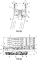
- the movement device 10 of the second conveyor 6 can be vertically movable along an axis substantially perpendicular to the platform 3 towards and away from the base 9, optionally from the platform 3, between a raised position and a lowered position, as shown respectively in figures 6B and 6C , and vice versa.
- the supporting surface of the movement device 10 of the second conveyor 6 is coplanar to the supporting surface of the first and second movement device 7, 8 of the first conveyor 5.
- the supporting surface of the movement device 10 of the second conveyor 6 is offset heightwise with respect to the supporting surface of the first and second movement device 7, 8 of the first conveyor 5.
- the supporting surface of the movement device 10 of the second conveyor 6, when arranged in the raised position, is placed at a height, measured along an axis perpendicular to such supporting surface, greater than a respective height level of the supporting surface of the first and second movement device 7, 8 of the first conveyor 5: in other words the supporting surface of the movement device 10 of the second conveyor 6 is placed, when in the raised position (see figure 6B ), at a height greater than the supporting surface of the first and second movement device 7, 8 of the first conveyor 5.
- the second conveyor 6, when arranged in the raised position allows supporting the sleepers T above the first conveyor 5 at the superimposition section without the sleepers T themselves contacting the first or with the second movement device 7, 8 of the first conveyor 5.
- the second conveyor 6 comprises, if the device 10 is vertically movable, a lifting actuator or a motor configured to cause the movement of the movement device 10 of the second conveyor 6 from the raised position to the lowered position and vice versa.
- the lifting motor can for example be an electric motor or a hydraulic or electric actuator.
- the movement device 10 of the second conveyor 6 is slidably movable along a direction substantially parallel to the platform 3 between a retracted position (see figures 5B and 5C ) in which the movement device 10 is placed in proximity to the first conveyor 5 and interposed between the first and the second movement device 7,8, and an extended position (see figure 6A , 6B and 6C ) in which the movement device 10 is spaced apart from the first conveyor 5.
- the second conveyor 6 comprises, as shown in detail in the side view of figure 6B , a guide device 11, interposed between the movement device 10 and the base 9, comprising a fixed guide 11a engaged with the base 9 by means of a constraint of hinge type, and a movable guide 11b carrying the movement device 10 and slidably movable with respect to the fixed guide 11a between the retracted position and the extended position, and vice versa.
- a guide device 11 interposed between the movement device 10 and the base 9 comprising a fixed guide 11a engaged with the base 9 by means of a constraint of hinge type, and a movable guide 11b carrying the movement device 10 and slidably movable with respect to the fixed guide 11a between the retracted position and the extended position, and vice versa.
- a guide device 11 interposed between the movement device 10 and the base 9 comprising a fixed guide 11a engaged with the base 9 by means of a constraint of hinge type, and a movable guide 11b carrying the movement device 10 and slid
- the movement device 10 when arranged in the retracted position, has the first section flanked to, and in particular interposed between, the first and the second movement device 7, 8 of the first conveyor 5, in a manner such to allow the exchange of the sleepers between the first and the second conveyor 5, 6.
- the second conveyor 6 comprises an extension motor/actuator 84 active on the guide 11 and configured to move the movable guide 11b from the retracted position to the extended position, and vice versa.
- the railway wagon 1 is connectable to a further adjacent railway wagon for example by means of an articulated joint; the further wagon can be in accordance with the above-described wagon 1 and comprise at least the first conveyor 5 as shown in figures 4, 5A , 5B and 5C .
- the second conveyor 6 of the railway wagon 1 allows, in particular when arranged in the extended position thereof, the exchange of the sleepers T between the railway wagon 1 and the further railway wagon, defining a bridge of exchange between the railway wagon 1 and the further railway wagon.
- the respective platforms are arranged along directions transverse to each other, as shown in figures 5A and 5B : in this circumstance, the railway wagons are not aligned with each other along a same direction.
- the second conveyor 6, due to the possibility of extension and contraction of the movement device 10 and to the degree of rotational freedom of the latter, allows transferring the sleepers T between two railway wagons even when these are tilted with respect to each other.
- the latter can be angularly aligned with the railway wagon on which the sleepers are arranged, as visible in figure 5A , the movement device 10 is initially aligned with the wagon 1 carrying the sleepers; following the passage of the sleepers on the adjacent wagon, the movement device can be angularly aligned with the latter as shown in figure 5B .
- the movement device 10 is capable of positioning the sleepers on the conveyors of the railway wagons exactly in the direction orthogonal to the advancement direction of the sleepers (see figures 1 , 4-5B , 6 and 7 ).
- the railway wagon 1 can comprise an angular sensor configured to emit a signal representative of the tilt between the railway wagon and the further railway wagon in a manner such to be able to manage the tilt of the movement device 10 so that the same can be adjusted as a function of the angular position of the conveyors of the single wagons 1.
- the railway wagon can comprise an auxiliary conveyor 15, shown in figures 2-4 , 10 and 11 , carried by the platform 3 and arranged opposite the second conveyor 6 with respect to the first conveyor 5 at the first end portion 3a of the platform 3.
- the auxiliary conveyor 15 extends longitudinally between a first and a second end portion 15a, 15b, in which the first end portion 15a is directed towards the first end portion 3a of the platform 3, while the second end portion 15b of the auxiliary conveyor 15 is directed towards the first end portion 5a of the first conveyor 5.
- the auxiliary conveyor 15 is at least partially interposed between the first end portion 3a of the platform 3 and the first end portion 5a of the first conveyor 5, and is configured to move sleepers T along the advancement direction A and for the direct exchange of sleepers T with the first conveyor 5.
- the auxiliary conveyor 15 extends between the first and the second end portion 15a, 15b along a prevalent development direction parallel to the prevalent development direction of the first conveyor 5: in particular the auxiliary conveyor 15 extends parallel to the prevalent development direction D of the platform 3, such that the first conveyor 5, the platform 3 and the auxiliary conveyor 15 are parallel to each other and preferably arranged along a same axis coinciding with the prevalent development direction D and with the advancement direction A.
- the auxiliary conveyor 15 comprises a base 18 fixed to the platform 3, and a movement device 16 defining a supporting surface adapted to support the sleepers T and allow the movement along the advancement direction A.
- the device 16 of the auxiliary conveyor 15 can in particular comprise at least one from between a conveyor belt and a transport roller, in which the conveyor belt can be made of plastic material or can be composed of a plurality of metallic meshes constrained to each other to define the belt itself.
- the conveyor 15 shown in figure 10 comprises a roller, having a plurality of rollers, each movable by rotation around a rotation axis thereof and arranged parallel to each other to define a supporting surface movable for the sleepers T.
- the rollers are preferably made of metallic material, such as steel, or of plastic or composite material.
- the auxiliary conveyor 15, and in particular the movement device 16 of the auxiliary conveyor 15, comprises a drive motor, for example an electric motor, configured to cause the movement of the sleepers T along the prevalent development direction D of the platform 3: in particular the drive motor is connected to the conveyor belt or to the roller in order respectively cause the movement or the rotation thereof.
- the motor can cause the movement of the sleepers T in both directions along the advancement direction A.
- the movement device 16 is engaged to the base 18 and is movable with respect to the latter along a pre-established direction substantially parallel to the advancement direction A and/or to the prevalent development direction D of the loading platform 3, between a retracted position, shown in figure 2 , and an extended position, shown in figure 3 .
- the movement device 16 of the auxiliary conveyor 15 In the retracted position, the movement device 16 of the auxiliary conveyor 15 has an end portion flanked to, and in particular interposed between, the first end portion 3a of the first and second movement device 7, 8 of the first conveyor 5, to define a superimposition section, while in the extended position the movement device 16 of the auxiliary conveyor 15 is entirely arranged outside the first and second movement device 7, 8 of the first conveyor 5.
- the maximum distance between the movement device 16 of the auxiliary conveyor 15 and the first conveyor 5, when in the extended position, is greater than a maximum distance present between the movement device 16 of the auxiliary conveyor 15 and the first conveyor 5 when the auxiliary conveyor is in the retracted position.
- the movement device 16 of the auxiliary conveyor 15 is movable towards and away the first conveyor 5 along a direction substantially parallel to and coinciding with the prevalent development direction D of the platform 3 and with the advancement direction A of the sleepers T.
- the auxiliary conveyor 15 comprises a guide device 17, directly carrying the movement device 16, comprising a fixed guide 17a engaged with the base 18 of the auxiliary conveyor 15 (e.g.
- the auxiliary conveyor 15 can comprise an extraction motor/actuator, e.g. electric or pneumatic, configured to cause the movement of the movement device 16 of the auxiliary conveyor 15 from the retracted position to the extended position and vice versa.
- the auxiliary conveyor 15 does not have a degree of rotational freedom with respect to the platform 3: in other words, the prevalent development direction of the auxiliary conveyor 15 is fixed and parallel to the prevalent development direction D of the platform 3.
- auxiliary conveyor 15 movable by rotation around an axis substantially perpendicular to the platform 3.
- the auxiliary conveyor can be idle in rotation around the rotation axis thereof or it can comprise one or more actuators or motors configured to cause the rotation thereof.
- the movement device 16 of the auxiliary conveyor 15 can be vertically movable along an axis substantially perpendicular to the platform 3 towards and away from the base 18, optionally from the platform 3, between a raised position and a lowered position and vice versa: such embodiment is not shown in the enclosed figures.
- the supporting surface of the movement device 16 of the auxiliary conveyor 15 is coplanar to the supporting surface of the first and second movement device 7, 8 of the first conveyor 5, while in the raised position the supporting surface of the movement device 16 of the auxiliary conveyor 15 is offset heightwise with respect to the supporting surface of the first and second movement device 7, 8 of the first conveyor 5.
- the supporting surface of the movement device 16 of the auxiliary conveyor 15, when arranged in the raised position, is placed at a height, measured along an axis perpendicular to such supporting surface, greater than a respective height of the supporting surface of the first and of the second movement device 7, 8 of the first conveyor 5.
- the supporting surface of the movement device 16 of the auxiliary conveyor 15 is placed, when in the raised position, at a height greater than the supporting surface of the first and second movement device 7, 8 of the first conveyor 5.
- the auxiliary conveyor 15, when arranged in the raised position allows carrying the sleepers T above the first conveyor 5 at the superimposition section without the sleepers T contacting the first or the second movement device 7, 8 of the first conveyor 5.
- the auxiliary conveyor 15 can comprise a lifting motor/actuator, e.g. electric or pneumatic, configured for causing the movement of the movement device 16 of the auxiliary conveyor 15 from the lowered position to the raised position and vice versa.
- the railway wagon can comprise a return conveyor 12, e.g. shown in figures 1 to 4 and 8 to 11 , configured to move sleepers along a return direction R substantially parallel to the advancement direction A and in the opposite direction to the latter.
- the return conveyor 12 is carried by the platform 3 and arranged above the first and of the second conveyor 5, 6 with respect to a direction orthogonal to the platform 3 at a distance from the first and/or from the second conveyor.
- the return conveyor 12 comprises at least one movement device 14 spaced apart from the first and second conveyor 5, 6 along a direction orthogonal to the platform 3, and extended along a prevalent development direction parallel to the prevalent development direction D of the platform 3, in more detail, parallel to the prevalent development direction of the first conveyor 5.
- the movement device 14 of the return conveyor 12 is then vertically aligned and raised with respect to the first and second conveyor 5, 6.
- the return conveyor 12, and in particular the movement device 14, comprises a transport roller or a conveyor belt connected to a drive motor, in particular an electric motor, configured to cause the movement thereof along the return direction R.
- the movement device 14 of the return conveyor 12 emerges outside the lateral size of the platform 3 at the first and/or second end portion 3a, 3b in order to allow the transit of sleepers between two adjacent railway wagons.
- the return conveyor 12 can comprise a single movement device 14 (see central railway wagon 1 of figure 1 ) or a first and a second movement device 14a, 14b (see end railway wagons 1 of figure 1 ).
- the return conveyor 12 comprises a support frame 13, made of metallic material such as steel, adapted to support the movement devices 14 above the first and second conveyors 5, 6.
- the support frame 13 comprises a plurality of lateral columns emerging heightwise from an end portion of the platform 3 in manner substantially perpendicular to the latter, and a plurality of crosspieces extended parallel to the platform 3 to support the movement device 14, in which each crosspiece is constrained to said plurality of columns.
- the support frame 13 defines a load-bearing structure having substantially C shape.
- the railway wagon 1 also comprises a stacked device 30 configured to receive a predetermined number of sleepers T arriving from the return conveyor 12, and move them from the return conveyor 12 to the auxiliary conveyor 15.
- the stacked device 30 has a grip device 31 movable for translation between an extended position shown in figures 9 and 11 , in which it is placed flanked to the return conveyor 12 and configured to receive and support the sleepers T arriving from the return conveyor 12, and a retracted position shown in figure 10 .
- the grip device 31 comprises a first and a second grip device 31a, 31b substantially parallel to each other and extended along a direction substantially parallel to the return direction R of the sleepers T: in particular the first and the second grip device 31a, 31b define a pair of arms extended along a main direction substantially parallel to the prevalent development direction of the movement device 14 of the return conveyor 12.
- the first and the second grip device 31a, 31b are spaced apart from each other and arranged at the margins of the maximum lateral size defined by the platform 3.
- the stacked device 30 When the stacked device 30 is in the extended position, an end portion of the movement device 14 of the return conveyor 12 is interposed between the first and the second grip device 31a, 31b, such that, in at least one operative condition, the sleepers T are simultaneously carried by the movement device 14 of the return conveyor 12 and by the grip device 31.
- the grip device 31 In the retracted position, however, the grip device 31 is not superimposed on the movement device 14 of the return conveyor 12, such that the sleepers T are arranged outside a vertical size of the movement device 14 of the return conveyor 12 and only supported by the grip device 31.
- the stacked device 30, and in particular the grip device 31, is also vertically movable along a direction substantially perpendicular to the platform 3, between a lowered position in which the stacked device is close to the platform 3, and a raised position in which the stacked device 30 is placed flanked to the movement device 14 of the return conveyor 12.
- the grip device 31 defines a support surface for the sleepers T, which is substantially coplanar to the movement device 14 of the return conveyor 12 when the grip device 31 is in the raised position, and substantially coplanar to the movement device 16 of the auxiliary conveyor when the grip device 31 is in the lowered position.
- the stacked device 30 is configured to receive a predetermined number of sleepers T arriving from the movement device 14 of the return conveyor 12, moving them from the extended position to the retracted position of the grip device 31 so as to remove them from the movement device 14 of the return conveyor 12, and subsequently move them from the raised position to the lowered position of the stacked device 30 in order to arrange such predetermined number of sleepers T on the movement device 16 of the auxiliary conveyor 15.
- the stacked device can comprise an extraction motor connected to the grip device 31 and configured to cause the movement thereof between the retracted position and the extended position and vice versa, and a lifting motor connected to the grip device 31 and configured to cause the movement thereof between the lowered position and the raised position and vice versa.
- the railway wagon 1 can comprise a collection station 20, shown in figures 1 to 4 and 10, 11 , comprising an auxiliary platform 21 carrying a collection conveyor 22, the latter extended along a pre-established prevalent development direction and adapted to receive, support and move a predetermined number of sleepers T along the development direction thereof.
- the auxiliary platform 21 preferably emerges from the first end 3a of the platform 3 of the railway wagon along the prevalent development direction of the platform 3 and is substantially coplanar to the platform 3.
- the collection conveyor 22 comprises a movement device 24 defining a supporting surface adapted to support the sleepers T and allow the movement thereof along a prevalent development direction thereof.
- the movement device 24 has at least one between a conveyor belt and a transport roller, in which the conveyor belt can be made of plastic material or it can be composed of a plurality of metallic meshes defining the belt itself.
- the movement device 24 of the collection conveyor 22 comprises a drive motor, e.g. an electric motor, configured to cause the movement of the sleepers T along the prevalent development direction of the movement device 24: in particular, said drive motor is connected to the conveyor belt or to the roller in order to respectively cause the movement or the rotation thereof.
- said motor can cause the movement of the sleepers T in both directions.
- the collection conveyor 22 is configured to rotate relative to the auxiliary platform 21 around an axis orthogonal to the auxiliary platform 21 itself between a first position and a second position.
- the prevalent development direction of the collection conveyor 22, and in particular of the movement device 24, is transverse with respect to the prevalent development direction of the auxiliary conveyor 15 or with respect to the prevalent development direction of the first conveyor 5, while in the second position the prevalent development direction of the collection conveyor 22 is parallel with respect to the prevalent development direction of the auxiliary conveyor 15 or with respect to prevalent development direction of the first conveyor 5.
- the collection conveyor 22 comprises a base 23 fixed to the auxiliary platform 21, and carrying the movement device 24, in which the latter is movable with respect to the latter around a rotation axis, as shown in figures 10 and 11 .
- the base 9 can be defined by a plate, for example made of metallic material such as steel and firmly constrained to the auxiliary platform 21 by means of bolted coupling or welding.
- the collection conveyor 22 can comprise a rotation motor 92 connected to the movement device 24 and configured to cause the rotation thereof between the first and the second position and vice versa.
- the collection conveyor 22 can also comprise a guide device, not shown in the enclosed figures, interposed between the movement device 24 and the base 23, comprising a fixed guide fixed to the base 23, and a movable guide carrying the movement device 24 and slidably movable with respect to the fixed guide between a retracted position and an extended position, and vice versa.
- a guide device not shown in the enclosed figures, interposed between the movement device 24 and the base 23, comprising a fixed guide fixed to the base 23, and a movable guide carrying the movement device 24 and slidably movable with respect to the fixed guide between a retracted position and an extended position, and vice versa.
- a guide device not shown in the enclosed figures, interposed between the movement device 24 and the base 23, comprising a fixed guide fixed to the base 23, and a movable guide carrying the movement device 24 and slidably movable with respect to the fixed guide between a retracted position and an extended position, and vice versa.
- such guide allows the extension and the contraction of the movement device
- the movable guide 17b of the auxiliary conveyor 15, in the extended position is then configured to arrange the movement device 16 of the auxiliary conveyor 15 in a position close to the collection conveyor 22 as shown in figure 3 , while, when in the retracted position, it is configured to arrange the movement device 16 of the auxiliary conveyor 15 in a spaced position with respect to the collection conveyor 22 as shown in figure 2 .
- the movement device 16 of the auxiliary conveyor 15, in the extended position of the movable guide 17b of the auxiliary conveyor 15 has a distance from the collection conveyor 22 lower than a same distance present when the movable guide 17b of the auxiliary conveyor 15 is in the retracted position.
- the movement device 16 is configured to exchange sleepers T with the collection conveyor 22 at least when the latter is arranged in the second position in which the collection conveyor 22 and the auxiliary conveyor 15 are aligned with each other (see figure 3 ).
- the collection conveyor 22 can comprise an extraction motor connected to the movement device 24 and configured to cause the movement thereof with respect to the auxiliary platform 21 from the extended position to the retracted position and vice versa.
- the collection conveyor can also be vertically movable along an axis substantially perpendicular to the auxiliary platform 21 between a lowered position and a raised position, as described above in relation to the movement device 16 of the auxiliary conveyor 15.
- the railway wagon 1 can also comprise, as shown in figures 1 and 8 , an unloading device 40 configured to receive a predetermined number of sleepers T arriving from the first and from the second conveyor 5, 6, in order to unload them from the railway wagon 1.
- the unloading device 40 is configured to unload such sleepers on the railway ballast, for example during works of maintenance or remaking of the railway ballast itself.
- the unloading device 40 preferably comprises a first and a second grip member 41a, 41b extended along a direction substantially parallel to the prevalent development direction of the platform 3 and of the advancement direction A of the sleepers T, to define a support surface for the sleepers T.
- the first and the second grip member 41a, 41b are parallel to each other and spaced by a height substantially equal to a lengthwise extension of the sleepers T.
- the grip members 41a, 41b of the unloading device 40 are also vertically movable along a direction substantially perpendicular to a plane lying along the platform 3 between a lowered position, in which the grip members 41a, 41b are placed at the level of the railway ballast and configured for depositing one or more sleepers T on the ground, a middle position in which the grip members 41a, 41b are coplanar to the first conveyor 5 and configured to receive the sleepers T arriving from the first and from the second conveyor 5, 6.
- the grip members 41a, 41b when arranged in the lowered position, have a distance from the ground that is lower than the same distance measured when the grip members 41a, 41b are arranged in the middle position.
- the grip members 41 are also movable heightwise up to a raised position, in which the grip members are arranged at a height level measured from the platform 3 greater than a same height measured when the grip members 41 are arranged in the middle or lowered position.
- the grip members 41 when arranged in the raised position are configured to transfer the sleepers T, in particular the worn sleepers T collected from the railway ballast, to the return conveyor 12.
- the railway wagon 1 can also comprise a cover 50 shown in figure 7 preferably made of metallic material, e.g. steel sheet metal, or made of plastic or composite material.
- the cover 50 emerges heightwise from perimeter portions of the platform 3 up to a top to define an external protection at least of the platform 3 and of the first and second conveyors 5, 6.
- the railway wagon 1 comprises or is associable with a control unit configured to control at least the first and the second conveyor 5, 6.
- the control unit is connected to the drive motor of the first conveyor 5, in particular of the first and of the second movement device 7, 8 of the first conveyor 5, and configured to cause the activation and stopping thereof.
- the control unit is configured to drive the speed of the drive motor in order to regulate the movement speed of the sleepers T along the advancement direction A when they are carried by the first conveyor 5.
- the control unit is also connected to the drive motor of the movement device 10 of the second conveyor 6 and configured to cause the activation and stopping thereof. Furthermore, the control unit is configured to control the speed of the drive motor in order to regulate the movement speed of the sleepers T along the prevalent development direction of the second conveyor 6 when arranged on the latter.
- the control unit is also connected to at least one from between the lifting motor, the rotation actuator and the extension motor of the movement device 10 of the second conveyor 6, in order to cause the activation and the stopping respectively of the vertical movement, of the rotation and of the movement between the retracted position and the extended position (and vice versa) of the movement device 10 of the second conveyor 6.
- the control unit can also be connected to the drive motor of the movement device 14 of the return conveyor 12 and configured to cause the activation and stopping thereof. Furthermore, the control unit is configured to control the speed of the drive motor in order to regulate the movement speed of the sleepers T along the return direction R.
- the control unit 60 can be connected to the lifting motor of the unloading device 40 and configured to cause the activation and stopping thereof; the control unit 60 is configured to control the speed of the lifting motor in order to regulate the lifting or lowering speed of the sleepers T along the vertical direction.
- the control unit can also be connected to at least one from between the extraction motor and the lifting motor of the stacked device 30; the control unit is configured to cause, for each motor, the activation and the stopping and to regulate the speed thereof.
- control unit is connected to at least one from between the drive motor, the lifting motor and the extraction motor; the control unit is configured to cause, for each motor, the activation and the stopping and optionally in order to control the speed thereof.
- control unit is connected to at least one from between the drive motor, the rotation motor and the extraction motor; the control unit is configured to determine, for each motor, the activation and the stopping and optionally in order to control the speed thereof.
- control unit is then configured to synchronize the activation and the stopping of the motors/actuators present on the railway wagon 1 in order to allow the movement of the sleepers T along the railway wagon itself along the advancement direction A and along the return direction R.
- the control unit is configured to:
- control unit is further configured to:
- control unit In an operative condition of the railway wagon, during the passage of the sleepers T from the auxiliary conveyor 15 to the first conveyor 5, the control unit can be configured to arrange the auxiliary conveyor 15 in the raised position until at least part of the sleepers T are arranged above the first conveyor 5 and spaced heightwise from the latter.
- control unit is further configured to:
- the vehicle 100 can comprise at least one first railway wagon 1a comprising the platform 3, the at least one carriage 4, the first conveyor 5 and the second conveyor 6, and a second railway wagon 1b comprising at least the platform 3, the first conveyor 5 and the unloading device 40.
- the second conveyor 6 defines a bridge between the first and the second railway wagon 1a, 1b in a manner such to allow the movement of the sleepers T from the first conveyor 5 of the first wagon 1a to the first conveyor 5 of the second wagon 1b.
- the first wagon 1a also comprises the auxiliary platform 21, the auxiliary conveyor 15 and the collection station 20, as shown in figure 1 .
- the vehicle 100 comprises at least two railway wagons; in particular, said railway vehicle 100 comprises:
- the railway vehicle 100 can comprise a plurality of middle wagons, in accordance with the above-reported description with reference to the first railway wagon 1, interposed between the tail wagon and the head wagon, comprising the platform 3, the first conveyor 5 and the second conveyor 6.
- At least one middle wagon can comprise the platform 3, the first conveyor 5 and two second conveyors 6 opposite each other and respectively arranged at the first and second end portions 3a, 3b of the loading platform 3.
- the vehicle 100 in accordance with the present invention, can be employed for remaking the railway ballast, in which it is necessary to remove from the ballast the sleepers T that are worn or damaged and substitute them with analogous new sleepers T.
- the vehicle 100 provides for the loading of new sleepers T, shown in the enclosed drawings in white, at the collection station 20 in order to move them by means of the first and the second conveyors 5, 6 along the plurality of railway wagons up to the unloading device 40, in a manner such to allow the deposit thereof on the railway ballast.
- the worn sleepers T shown in the enclosed drawings covered with dots, are then removed and moved by means of the same unloading device 40 towards the return conveyor 12, which causes the movement thereof up to the collection station 20 in order to allow the subsequent unloading thereof.
- Also forming the object of present invention is a process for moving sleepers by means of a vehicle 100 in accordance with the above-reported description and/or in accordance with any one of the enclosed claims.
- the process can be implemented for making or renovating railway lines.
- the process provides for comprising a first step of loading sleepers (new sleepers to be installed or to be substituted in place of old sleepers) on a railway wagon 1, for example a tail wagon, by means of the collection station.
- sleepers new sleepers to be installed or to be substituted in place of old sleepers
- the sleepers loaded on the tail railway wagon are initially placed on the auxiliary platform and by means of the auxiliary conveyor they are moved on the first conveyor.
- the first conveyor 5 moves the sleepers along the longitudinal extension of the tail wagon 1 up to a second conveyor 6 of the same wagon.
- the second conveyor 6 is at the time angularly aligned (parallel) with the first conveyor 5 of the tail wagon when it receives the sleepers; the second conveyor extends outside the lateral size of the tail wagon and moves the sleepers received from the first conveyor outside said tail wagon up to serving said sleepers to a first conveyor of an adjacent railway wagon, for example an intermediate wagon.
- the intermediate railway wagon also has the platform, the first conveyor 5 and the second conveyor 6; the intermediate wagon which receives the sleepers moves them along the extension thereof by means of the first conveyor 5 away from the tail wagon, up to serving the second conveyor 6 thereof.
- the second conveyor 6 of the intermediate railway wagon 1 moves the sleepers outside the lateral size of the railway wagon in order to serve an adjacent railway wagon and in particular a first conveyor 5 of the adjacent railway wagon.
- the process can provide for the movement of sleepers through a plurality of intermediate railway wagons up to reaching a first conveyor 5 of a head railway wagon 1.
- the head railway wagon 1 comprises the platform, the first conveyor 5 and the unloading device.
- the sleepers that reach the unloading device are unloaded from the railway vehicle 100.
- the process can also provide for the recovery of old sleepers from pre-existing railway lines; the old sleepers are initially loaded on the return conveyor 12 that is raised with respect to the conveyors 5 and 6 of the vehicle.
- the conveyor moves the old sleepers from the head railway wagon 1, through the intermediate railway wagons, up to the tail railway wagon 1 where the old sleepers are unloaded from the vehicle.
- the present invention allows obtaining important advantages.
- due to the presence of the second conveyor 6 movable by rotation it allows the movement of the sleepers T between one railway wagon and the next even when the wagons are tilted with respect to each other.
- the present finding allows a quick and continuous movement of the sleepers along the railway wagons without having to interrupt their movement if the wagons are tilted with respect to each other, which occurs if the wagons are arranged on a curve along a railway: this determines a substantial increase of speed during the work operations for repairing or maintaining the railway ballast.
- the present finding has a simple, compact and therefore light structure; the wagon and the railway vehicle, object of the present invention, have an improved load capacity with respect to the preceding solutions. It is also indicated that the simple and compact structure positively affects the production costs and also allows minimizing the costs for possible repair and maintenance interventions.
Landscapes
- Engineering & Computer Science (AREA)
- Mechanical Engineering (AREA)
- Transportation (AREA)
- Architecture (AREA)
- Civil Engineering (AREA)
- Structural Engineering (AREA)
- Aviation & Aerospace Engineering (AREA)
- Intermediate Stations On Conveyors (AREA)
- Loading Or Unloading Of Vehicles (AREA)
- Machines For Laying And Maintaining Railways (AREA)
Applications Claiming Priority (1)
| Application Number | Priority Date | Filing Date | Title |
|---|---|---|---|
| IT102019000008283A IT201900008283A1 (it) | 2019-06-06 | 2019-06-06 | Carro ferroviario per la movimentazione di traversine, veicolo ferroviario comprendente detto carro |
Publications (2)
| Publication Number | Publication Date |
|---|---|
| EP3748081A1 true EP3748081A1 (de) | 2020-12-09 |
| EP3748081B1 EP3748081B1 (de) | 2022-08-31 |
Family
ID=68138640
Family Applications (1)
| Application Number | Title | Priority Date | Filing Date |
|---|---|---|---|
| EP20172034.9A Active EP3748081B1 (de) | 2019-06-06 | 2020-04-29 | Schienenwagen zum bewegen von schwellen, schienenfahrzeug mit derartigem schienenwagen |
Country Status (3)
| Country | Link |
|---|---|
| US (1) | US11674268B2 (de) |
| EP (1) | EP3748081B1 (de) |
| IT (1) | IT201900008283A1 (de) |
Families Citing this family (5)
| Publication number | Priority date | Publication date | Assignee | Title |
|---|---|---|---|---|
| US11225758B1 (en) * | 2019-06-26 | 2022-01-18 | Union Pacific Railroad Company | Automated railroad tie unloading |
| CN114318971B (zh) * | 2021-07-13 | 2023-09-01 | 中铁建工集团有限公司 | 一种铁路施工时的快速排料装置 |
| US20230220632A1 (en) * | 2022-01-10 | 2023-07-13 | Transportation Ip Holdings, Llc | Rail tie handling system and method |
| DE102022128184A1 (de) * | 2022-10-25 | 2024-04-25 | K & K Maschinenentwicklungs Gmbh & Co. Kg | System zum gleisgebundenen Transport von Gegenständen |
| CN117262626B (zh) * | 2023-11-20 | 2024-03-26 | 中建安装集团有限公司 | 一种智能轨枕运输系统及运输方法 |
Citations (4)
| Publication number | Priority date | Publication date | Assignee | Title |
|---|---|---|---|---|
| US3638577A (en) * | 1968-10-16 | 1972-02-01 | Plasser Bahnbaumasch Franz | Mobile apparatus for laying track ties |
| US5347934A (en) | 1992-12-22 | 1994-09-20 | Macbon Pty. Ltd. | Sleeper laying apparatus |
| US20040045472A1 (en) | 2002-09-05 | 2004-03-11 | Franz Plasser Bahnbaumaschinen-Industriegesellschaft M.B.H. | Machine for remving an old track and laying a new track |
| WO2019129678A1 (de) * | 2017-12-28 | 2019-07-04 | Plasser & Theurer Export Von Bahnbaumaschinen Gmbh | Schwellentransportfahrzeug |
Family Cites Families (3)
| Publication number | Priority date | Publication date | Assignee | Title |
|---|---|---|---|---|
| AT515699B1 (de) * | 2014-07-01 | 2015-11-15 | Plasser & Theurer Export Von Bahnbaumaschinen Gmbh | Verladewagen |
| AT516471B1 (de) * | 2014-10-27 | 2017-02-15 | Hp3 Real Gmbh | Vorrichtung zur Materialförderung für den Gleisbau |
| US10286929B2 (en) * | 2016-06-09 | 2019-05-14 | Georgetown Rail Equipment Company | Aggregate train and methods of loading and unloading |
-
2019
- 2019-06-06 IT IT102019000008283A patent/IT201900008283A1/it unknown
-
2020
- 2020-04-29 EP EP20172034.9A patent/EP3748081B1/de active Active
- 2020-06-05 US US16/893,887 patent/US11674268B2/en active Active
Patent Citations (4)
| Publication number | Priority date | Publication date | Assignee | Title |
|---|---|---|---|---|
| US3638577A (en) * | 1968-10-16 | 1972-02-01 | Plasser Bahnbaumasch Franz | Mobile apparatus for laying track ties |
| US5347934A (en) | 1992-12-22 | 1994-09-20 | Macbon Pty. Ltd. | Sleeper laying apparatus |
| US20040045472A1 (en) | 2002-09-05 | 2004-03-11 | Franz Plasser Bahnbaumaschinen-Industriegesellschaft M.B.H. | Machine for remving an old track and laying a new track |
| WO2019129678A1 (de) * | 2017-12-28 | 2019-07-04 | Plasser & Theurer Export Von Bahnbaumaschinen Gmbh | Schwellentransportfahrzeug |
Also Published As
| Publication number | Publication date |
|---|---|
| IT201900008283A1 (it) | 2020-12-06 |
| US20200385934A1 (en) | 2020-12-10 |
| US11674268B2 (en) | 2023-06-13 |
| EP3748081B1 (de) | 2022-08-31 |
Similar Documents
| Publication | Publication Date | Title |
|---|---|---|
| EP3748081A1 (de) | Schienenwagen zum bewegen von schwellen, schienenfahrzeug mit derartigem schienenwagen | |
| US5577597A (en) | Work transport system including pallet transport apparatus | |
| US9045182B2 (en) | Plant for assembling mechanical parts on bodies of motor-vehicles | |
| US7798316B2 (en) | Robotic frame handling system | |
| US6722836B2 (en) | Linked manufacturing system for processing parts | |
| CN105705441A (zh) | 自动存储和取回系统 | |
| US5762464A (en) | Railroad car for loading and unloading rails | |
| CN108367862A (zh) | 自动货仓系统和用于在所述货仓系统中存放挂装货物的方法 | |
| EP2570372A1 (de) | Frachthandhabungssystem | |
| EP0167235A1 (de) | Beförderungssystem | |
| US9446905B2 (en) | Feed device and method | |
| CN211140612U (zh) | 一种rgv小车 | |
| DE102006014532A1 (de) | Vorrichtung zur Förderung einer oder mehrerer Materialrollen mit einem Transportsystem und einer Rollengreifeinrichtung zur Aufnahme der Materialrolle | |
| US7287953B2 (en) | Method for loading and unloading | |
| US7455492B2 (en) | Multi-trolley container crane with bi-level track switching capability | |
| CZ20024172A3 (cs) | Zařízení na přepravu a šikmé nakládání a vykládání vozidel v železniční stanici pro kombinovanou přepravu železničních a silničních vozidel a způsob jeho využití | |
| JP5626579B2 (ja) | 物品搬送装置及びこれを備えた物品搬送用の移動体 | |
| MXPA05009199A (es) | Dispositivo de control de almacen y sistema para la preparacion y almacenamiento intermedio de rollos de papel y para la alimentacion de los mismos a por lo menos un soporte de rollo y metodo para su operacion. | |
| CN111492109A (zh) | 轨枕运输车 | |
| US7153078B2 (en) | Loading and unloading station and method for load carrier of vehicle bodies, vehicles and the like | |
| JP4265460B2 (ja) | 無人搬送車による部品供給装置 | |
| US20020015637A1 (en) | Straddle loader for ISO containers | |
| JP2023539543A (ja) | ロールシャトルおよび懸架式ロールシャトル | |
| CN109748120B (zh) | 一种用于自动化码头集装箱的智能装卸装置及其工作方法 | |
| KR100590316B1 (ko) | 적재물 분배 공급장치 |
Legal Events
| Date | Code | Title | Description |
|---|---|---|---|
| PUAI | Public reference made under article 153(3) epc to a published international application that has entered the european phase |
Free format text: ORIGINAL CODE: 0009012 |
|
| STAA | Information on the status of an ep patent application or granted ep patent |
Free format text: STATUS: THE APPLICATION HAS BEEN PUBLISHED |
|
| AK | Designated contracting states |
Kind code of ref document: A1 Designated state(s): AL AT BE BG CH CY CZ DE DK EE ES FI FR GB GR HR HU IE IS IT LI LT LU LV MC MK MT NL NO PL PT RO RS SE SI SK SM TR |
|
| AX | Request for extension of the european patent |
Extension state: BA ME |
|
| STAA | Information on the status of an ep patent application or granted ep patent |
Free format text: STATUS: REQUEST FOR EXAMINATION WAS MADE |
|
| 17P | Request for examination filed |
Effective date: 20210528 |
|
| RBV | Designated contracting states (corrected) |
Designated state(s): AL AT BE BG CH CY CZ DE DK EE ES FI FR GB GR HR HU IE IS IT LI LT LU LV MC MK MT NL NO PL PT RO RS SE SI SK SM TR |
|
| GRAP | Despatch of communication of intention to grant a patent |
Free format text: ORIGINAL CODE: EPIDOSNIGR1 |
|
| STAA | Information on the status of an ep patent application or granted ep patent |
Free format text: STATUS: GRANT OF PATENT IS INTENDED |
|
| INTG | Intention to grant announced |
Effective date: 20220202 |
|
| RIN1 | Information on inventor provided before grant (corrected) |
Inventor name: SALCICCIA, GILBERTO |
|
| GRAJ | Information related to disapproval of communication of intention to grant by the applicant or resumption of examination proceedings by the epo deleted |
Free format text: ORIGINAL CODE: EPIDOSDIGR1 |
|
| STAA | Information on the status of an ep patent application or granted ep patent |
Free format text: STATUS: REQUEST FOR EXAMINATION WAS MADE |
|
| INTC | Intention to grant announced (deleted) | ||
| GRAP | Despatch of communication of intention to grant a patent |
Free format text: ORIGINAL CODE: EPIDOSNIGR1 |
|
| STAA | Information on the status of an ep patent application or granted ep patent |
Free format text: STATUS: GRANT OF PATENT IS INTENDED |
|
| INTG | Intention to grant announced |
Effective date: 20220506 |
|
| GRAS | Grant fee paid |
Free format text: ORIGINAL CODE: EPIDOSNIGR3 |
|
| GRAA | (expected) grant |
Free format text: ORIGINAL CODE: 0009210 |
|
| STAA | Information on the status of an ep patent application or granted ep patent |
Free format text: STATUS: THE PATENT HAS BEEN GRANTED |
|
| AK | Designated contracting states |
Kind code of ref document: B1 Designated state(s): AL AT BE BG CH CY CZ DE DK EE ES FI FR GB GR HR HU IE IS IT LI LT LU LV MC MK MT NL NO PL PT RO RS SE SI SK SM TR |
|
| REG | Reference to a national code |
Ref country code: CH Ref legal event code: EP Ref country code: GB Ref legal event code: FG4D |
|
| REG | Reference to a national code |
Ref country code: AT Ref legal event code: REF Ref document number: 1515366 Country of ref document: AT Kind code of ref document: T Effective date: 20220915 |
|
| REG | Reference to a national code |
Ref country code: DE Ref legal event code: R096 Ref document number: 602020004783 Country of ref document: DE |
|
| REG | Reference to a national code |
Ref country code: IE Ref legal event code: FG4D |
|
| REG | Reference to a national code |
Ref country code: LT Ref legal event code: MG9D |
|
| REG | Reference to a national code |
Ref country code: NL Ref legal event code: MP Effective date: 20220831 |
|
| PG25 | Lapsed in a contracting state [announced via postgrant information from national office to epo] |
Ref country code: SE Free format text: LAPSE BECAUSE OF FAILURE TO SUBMIT A TRANSLATION OF THE DESCRIPTION OR TO PAY THE FEE WITHIN THE PRESCRIBED TIME-LIMIT Effective date: 20220831 Ref country code: RS Free format text: LAPSE BECAUSE OF FAILURE TO SUBMIT A TRANSLATION OF THE DESCRIPTION OR TO PAY THE FEE WITHIN THE PRESCRIBED TIME-LIMIT Effective date: 20220831 Ref country code: NO Free format text: LAPSE BECAUSE OF FAILURE TO SUBMIT A TRANSLATION OF THE DESCRIPTION OR TO PAY THE FEE WITHIN THE PRESCRIBED TIME-LIMIT Effective date: 20221130 Ref country code: LV Free format text: LAPSE BECAUSE OF FAILURE TO SUBMIT A TRANSLATION OF THE DESCRIPTION OR TO PAY THE FEE WITHIN THE PRESCRIBED TIME-LIMIT Effective date: 20220831 Ref country code: LT Free format text: LAPSE BECAUSE OF FAILURE TO SUBMIT A TRANSLATION OF THE DESCRIPTION OR TO PAY THE FEE WITHIN THE PRESCRIBED TIME-LIMIT Effective date: 20220831 Ref country code: FI Free format text: LAPSE BECAUSE OF FAILURE TO SUBMIT A TRANSLATION OF THE DESCRIPTION OR TO PAY THE FEE WITHIN THE PRESCRIBED TIME-LIMIT Effective date: 20220831 |
|
| REG | Reference to a national code |
Ref country code: AT Ref legal event code: MK05 Ref document number: 1515366 Country of ref document: AT Kind code of ref document: T Effective date: 20220831 |
|
| PG25 | Lapsed in a contracting state [announced via postgrant information from national office to epo] |
Ref country code: PL Free format text: LAPSE BECAUSE OF FAILURE TO SUBMIT A TRANSLATION OF THE DESCRIPTION OR TO PAY THE FEE WITHIN THE PRESCRIBED TIME-LIMIT Effective date: 20220831 Ref country code: IS Free format text: LAPSE BECAUSE OF FAILURE TO SUBMIT A TRANSLATION OF THE DESCRIPTION OR TO PAY THE FEE WITHIN THE PRESCRIBED TIME-LIMIT Effective date: 20221231 Ref country code: HR Free format text: LAPSE BECAUSE OF FAILURE TO SUBMIT A TRANSLATION OF THE DESCRIPTION OR TO PAY THE FEE WITHIN THE PRESCRIBED TIME-LIMIT Effective date: 20220831 Ref country code: GR Free format text: LAPSE BECAUSE OF FAILURE TO SUBMIT A TRANSLATION OF THE DESCRIPTION OR TO PAY THE FEE WITHIN THE PRESCRIBED TIME-LIMIT Effective date: 20221201 |
|
| PG25 | Lapsed in a contracting state [announced via postgrant information from national office to epo] |
Ref country code: SM Free format text: LAPSE BECAUSE OF FAILURE TO SUBMIT A TRANSLATION OF THE DESCRIPTION OR TO PAY THE FEE WITHIN THE PRESCRIBED TIME-LIMIT Effective date: 20220831 Ref country code: RO Free format text: LAPSE BECAUSE OF FAILURE TO SUBMIT A TRANSLATION OF THE DESCRIPTION OR TO PAY THE FEE WITHIN THE PRESCRIBED TIME-LIMIT Effective date: 20220831 Ref country code: PT Free format text: LAPSE BECAUSE OF FAILURE TO SUBMIT A TRANSLATION OF THE DESCRIPTION OR TO PAY THE FEE WITHIN THE PRESCRIBED TIME-LIMIT Effective date: 20230102 Ref country code: ES Free format text: LAPSE BECAUSE OF FAILURE TO SUBMIT A TRANSLATION OF THE DESCRIPTION OR TO PAY THE FEE WITHIN THE PRESCRIBED TIME-LIMIT Effective date: 20220831 Ref country code: DK Free format text: LAPSE BECAUSE OF FAILURE TO SUBMIT A TRANSLATION OF THE DESCRIPTION OR TO PAY THE FEE WITHIN THE PRESCRIBED TIME-LIMIT Effective date: 20220831 Ref country code: CZ Free format text: LAPSE BECAUSE OF FAILURE TO SUBMIT A TRANSLATION OF THE DESCRIPTION OR TO PAY THE FEE WITHIN THE PRESCRIBED TIME-LIMIT Effective date: 20220831 Ref country code: AT Free format text: LAPSE BECAUSE OF FAILURE TO SUBMIT A TRANSLATION OF THE DESCRIPTION OR TO PAY THE FEE WITHIN THE PRESCRIBED TIME-LIMIT Effective date: 20220831 |
|
| PG25 | Lapsed in a contracting state [announced via postgrant information from national office to epo] |
Ref country code: SK Free format text: LAPSE BECAUSE OF FAILURE TO SUBMIT A TRANSLATION OF THE DESCRIPTION OR TO PAY THE FEE WITHIN THE PRESCRIBED TIME-LIMIT Effective date: 20220831 Ref country code: EE Free format text: LAPSE BECAUSE OF FAILURE TO SUBMIT A TRANSLATION OF THE DESCRIPTION OR TO PAY THE FEE WITHIN THE PRESCRIBED TIME-LIMIT Effective date: 20220831 |
|
| REG | Reference to a national code |
Ref country code: DE Ref legal event code: R097 Ref document number: 602020004783 Country of ref document: DE |
|
| P01 | Opt-out of the competence of the unified patent court (upc) registered |
Effective date: 20230518 |
|
| PG25 | Lapsed in a contracting state [announced via postgrant information from national office to epo] |
Ref country code: NL Free format text: LAPSE BECAUSE OF FAILURE TO SUBMIT A TRANSLATION OF THE DESCRIPTION OR TO PAY THE FEE WITHIN THE PRESCRIBED TIME-LIMIT Effective date: 20220831 Ref country code: AL Free format text: LAPSE BECAUSE OF FAILURE TO SUBMIT A TRANSLATION OF THE DESCRIPTION OR TO PAY THE FEE WITHIN THE PRESCRIBED TIME-LIMIT Effective date: 20220831 |
|
| PLBE | No opposition filed within time limit |
Free format text: ORIGINAL CODE: 0009261 |
|
| STAA | Information on the status of an ep patent application or granted ep patent |
Free format text: STATUS: NO OPPOSITION FILED WITHIN TIME LIMIT |
|
| PGFP | Annual fee paid to national office [announced via postgrant information from national office to epo] |
Ref country code: IT Payment date: 20230501 Year of fee payment: 4 Ref country code: FR Payment date: 20230421 Year of fee payment: 4 Ref country code: DE Payment date: 20230427 Year of fee payment: 4 Ref country code: CH Payment date: 20230502 Year of fee payment: 4 |
|
| 26N | No opposition filed |
Effective date: 20230601 |
|
| PG25 | Lapsed in a contracting state [announced via postgrant information from national office to epo] |
Ref country code: SI Free format text: LAPSE BECAUSE OF FAILURE TO SUBMIT A TRANSLATION OF THE DESCRIPTION OR TO PAY THE FEE WITHIN THE PRESCRIBED TIME-LIMIT Effective date: 20220831 |
|
| PG25 | Lapsed in a contracting state [announced via postgrant information from national office to epo] |
Ref country code: LU Free format text: LAPSE BECAUSE OF NON-PAYMENT OF DUE FEES Effective date: 20230429 |
|
| REG | Reference to a national code |
Ref country code: BE Ref legal event code: MM Effective date: 20230430 |
|
| PG25 | Lapsed in a contracting state [announced via postgrant information from national office to epo] |
Ref country code: MC Free format text: LAPSE BECAUSE OF FAILURE TO SUBMIT A TRANSLATION OF THE DESCRIPTION OR TO PAY THE FEE WITHIN THE PRESCRIBED TIME-LIMIT Effective date: 20220831 |
|
| PG25 | Lapsed in a contracting state [announced via postgrant information from national office to epo] |
Ref country code: MC Free format text: LAPSE BECAUSE OF FAILURE TO SUBMIT A TRANSLATION OF THE DESCRIPTION OR TO PAY THE FEE WITHIN THE PRESCRIBED TIME-LIMIT Effective date: 20220831 |
|
| REG | Reference to a national code |
Ref country code: IE Ref legal event code: MM4A |
|
| PG25 | Lapsed in a contracting state [announced via postgrant information from national office to epo] |
Ref country code: BE Free format text: LAPSE BECAUSE OF NON-PAYMENT OF DUE FEES Effective date: 20230430 |
|
| PG25 | Lapsed in a contracting state [announced via postgrant information from national office to epo] |
Ref country code: IE Free format text: LAPSE BECAUSE OF NON-PAYMENT OF DUE FEES Effective date: 20230429 |
|
| PG25 | Lapsed in a contracting state [announced via postgrant information from national office to epo] |
Ref country code: IE Free format text: LAPSE BECAUSE OF NON-PAYMENT OF DUE FEES Effective date: 20230429 |