EP3746377B1 - Paroi de cuve étanche, procédé de montage de paroi de cuve étanche, navire, procédé de chargement/déchargement d'un navire, système de transfert pour un produit liquide froid - Google Patents
Paroi de cuve étanche, procédé de montage de paroi de cuve étanche, navire, procédé de chargement/déchargement d'un navire, système de transfert pour un produit liquide froid Download PDFInfo
- Publication number
- EP3746377B1 EP3746377B1 EP19707444.6A EP19707444A EP3746377B1 EP 3746377 B1 EP3746377 B1 EP 3746377B1 EP 19707444 A EP19707444 A EP 19707444A EP 3746377 B1 EP3746377 B1 EP 3746377B1
- Authority
- EP
- European Patent Office
- Prior art keywords
- wave
- reinforcements
- wave reinforcements
- corrugations
- connecting member
- Prior art date
- Legal status (The legal status is an assumption and is not a legal conclusion. Google has not performed a legal analysis and makes no representation as to the accuracy of the status listed.)
- Active
Links
Images




Classifications
-
- F—MECHANICAL ENGINEERING; LIGHTING; HEATING; WEAPONS; BLASTING
- F17—STORING OR DISTRIBUTING GASES OR LIQUIDS
- F17C—VESSELS FOR CONTAINING OR STORING COMPRESSED, LIQUEFIED OR SOLIDIFIED GASES; FIXED-CAPACITY GAS-HOLDERS; FILLING VESSELS WITH, OR DISCHARGING FROM VESSELS, COMPRESSED, LIQUEFIED, OR SOLIDIFIED GASES
- F17C3/00—Vessels not under pressure
- F17C3/02—Vessels not under pressure with provision for thermal insulation
- F17C3/025—Bulk storage in barges or on ships
- F17C3/027—Wallpanels for so-called membrane tanks
-
- B—PERFORMING OPERATIONS; TRANSPORTING
- B65—CONVEYING; PACKING; STORING; HANDLING THIN OR FILAMENTARY MATERIAL
- B65D—CONTAINERS FOR STORAGE OR TRANSPORT OF ARTICLES OR MATERIALS, e.g. BAGS, BARRELS, BOTTLES, BOXES, CANS, CARTONS, CRATES, DRUMS, JARS, TANKS, HOPPERS, FORWARDING CONTAINERS; ACCESSORIES, CLOSURES, OR FITTINGS THEREFOR; PACKAGING ELEMENTS; PACKAGES
- B65D90/00—Component parts, details or accessories for large containers
- B65D90/02—Wall construction
- B65D90/027—Corrugated or zig-zag structures; Folded plate
-
- B—PERFORMING OPERATIONS; TRANSPORTING
- B65—CONVEYING; PACKING; STORING; HANDLING THIN OR FILAMENTARY MATERIAL
- B65D—CONTAINERS FOR STORAGE OR TRANSPORT OF ARTICLES OR MATERIALS, e.g. BAGS, BARRELS, BOTTLES, BOXES, CANS, CARTONS, CRATES, DRUMS, JARS, TANKS, HOPPERS, FORWARDING CONTAINERS; ACCESSORIES, CLOSURES, OR FITTINGS THEREFOR; PACKAGING ELEMENTS; PACKAGES
- B65D90/00—Component parts, details or accessories for large containers
- B65D90/02—Wall construction
- B65D90/04—Linings
- B65D90/041—Rigid liners fixed to the container
-
- B—PERFORMING OPERATIONS; TRANSPORTING
- B67—OPENING, CLOSING OR CLEANING BOTTLES, JARS OR SIMILAR CONTAINERS; LIQUID HANDLING
- B67D—DISPENSING, DELIVERING OR TRANSFERRING LIQUIDS, NOT OTHERWISE PROVIDED FOR
- B67D7/00—Apparatus or devices for transferring liquids from bulk storage containers or reservoirs into vehicles or into portable containers, e.g. for retail sale purposes
- B67D7/06—Details or accessories
- B67D7/38—Arrangements of hoses, e.g. operative connection with pump motor
-
- B—PERFORMING OPERATIONS; TRANSPORTING
- B67—OPENING, CLOSING OR CLEANING BOTTLES, JARS OR SIMILAR CONTAINERS; LIQUID HANDLING
- B67D—DISPENSING, DELIVERING OR TRANSFERRING LIQUIDS, NOT OTHERWISE PROVIDED FOR
- B67D7/00—Apparatus or devices for transferring liquids from bulk storage containers or reservoirs into vehicles or into portable containers, e.g. for retail sale purposes
- B67D7/06—Details or accessories
- B67D7/58—Arrangements of pumps
-
- B—PERFORMING OPERATIONS; TRANSPORTING
- B67—OPENING, CLOSING OR CLEANING BOTTLES, JARS OR SIMILAR CONTAINERS; LIQUID HANDLING
- B67D—DISPENSING, DELIVERING OR TRANSFERRING LIQUIDS, NOT OTHERWISE PROVIDED FOR
- B67D9/00—Apparatus or devices for transferring liquids when loading or unloading ships
-
- F—MECHANICAL ENGINEERING; LIGHTING; HEATING; WEAPONS; BLASTING
- F17—STORING OR DISTRIBUTING GASES OR LIQUIDS
- F17C—VESSELS FOR CONTAINING OR STORING COMPRESSED, LIQUEFIED OR SOLIDIFIED GASES; FIXED-CAPACITY GAS-HOLDERS; FILLING VESSELS WITH, OR DISCHARGING FROM VESSELS, COMPRESSED, LIQUEFIED, OR SOLIDIFIED GASES
- F17C13/00—Details of vessels or of the filling or discharging of vessels
- F17C13/004—Details of vessels or of the filling or discharging of vessels for large storage vessels not under pressure
-
- F—MECHANICAL ENGINEERING; LIGHTING; HEATING; WEAPONS; BLASTING
- F17—STORING OR DISTRIBUTING GASES OR LIQUIDS
- F17C—VESSELS FOR CONTAINING OR STORING COMPRESSED, LIQUEFIED OR SOLIDIFIED GASES; FIXED-CAPACITY GAS-HOLDERS; FILLING VESSELS WITH, OR DISCHARGING FROM VESSELS, COMPRESSED, LIQUEFIED, OR SOLIDIFIED GASES
- F17C3/00—Vessels not under pressure
- F17C3/02—Vessels not under pressure with provision for thermal insulation
- F17C3/04—Vessels not under pressure with provision for thermal insulation by insulating layers
-
- B—PERFORMING OPERATIONS; TRANSPORTING
- B65—CONVEYING; PACKING; STORING; HANDLING THIN OR FILAMENTARY MATERIAL
- B65D—CONTAINERS FOR STORAGE OR TRANSPORT OF ARTICLES OR MATERIALS, e.g. BAGS, BARRELS, BOTTLES, BOXES, CANS, CARTONS, CRATES, DRUMS, JARS, TANKS, HOPPERS, FORWARDING CONTAINERS; ACCESSORIES, CLOSURES, OR FITTINGS THEREFOR; PACKAGING ELEMENTS; PACKAGES
- B65D2588/00—Large container
- B65D2588/02—Large container rigid
- B65D2588/12—Large container rigid specially adapted for transport
-
- F—MECHANICAL ENGINEERING; LIGHTING; HEATING; WEAPONS; BLASTING
- F17—STORING OR DISTRIBUTING GASES OR LIQUIDS
- F17C—VESSELS FOR CONTAINING OR STORING COMPRESSED, LIQUEFIED OR SOLIDIFIED GASES; FIXED-CAPACITY GAS-HOLDERS; FILLING VESSELS WITH, OR DISCHARGING FROM VESSELS, COMPRESSED, LIQUEFIED, OR SOLIDIFIED GASES
- F17C2201/00—Vessel construction, in particular geometry, arrangement or size
- F17C2201/01—Shape
- F17C2201/0147—Shape complex
- F17C2201/0157—Polygonal
-
- F—MECHANICAL ENGINEERING; LIGHTING; HEATING; WEAPONS; BLASTING
- F17—STORING OR DISTRIBUTING GASES OR LIQUIDS
- F17C—VESSELS FOR CONTAINING OR STORING COMPRESSED, LIQUEFIED OR SOLIDIFIED GASES; FIXED-CAPACITY GAS-HOLDERS; FILLING VESSELS WITH, OR DISCHARGING FROM VESSELS, COMPRESSED, LIQUEFIED, OR SOLIDIFIED GASES
- F17C2201/00—Vessel construction, in particular geometry, arrangement or size
- F17C2201/05—Size
- F17C2201/052—Size large (>1000 m3)
-
- F—MECHANICAL ENGINEERING; LIGHTING; HEATING; WEAPONS; BLASTING
- F17—STORING OR DISTRIBUTING GASES OR LIQUIDS
- F17C—VESSELS FOR CONTAINING OR STORING COMPRESSED, LIQUEFIED OR SOLIDIFIED GASES; FIXED-CAPACITY GAS-HOLDERS; FILLING VESSELS WITH, OR DISCHARGING FROM VESSELS, COMPRESSED, LIQUEFIED, OR SOLIDIFIED GASES
- F17C2203/00—Vessel construction, in particular walls or details thereof
- F17C2203/01—Reinforcing or suspension means
- F17C2203/011—Reinforcing means
- F17C2203/012—Reinforcing means on or in the wall, e.g. ribs
-
- F—MECHANICAL ENGINEERING; LIGHTING; HEATING; WEAPONS; BLASTING
- F17—STORING OR DISTRIBUTING GASES OR LIQUIDS
- F17C—VESSELS FOR CONTAINING OR STORING COMPRESSED, LIQUEFIED OR SOLIDIFIED GASES; FIXED-CAPACITY GAS-HOLDERS; FILLING VESSELS WITH, OR DISCHARGING FROM VESSELS, COMPRESSED, LIQUEFIED, OR SOLIDIFIED GASES
- F17C2203/00—Vessel construction, in particular walls or details thereof
- F17C2203/03—Thermal insulations
- F17C2203/0304—Thermal insulations by solid means
- F17C2203/0358—Thermal insulations by solid means in form of panels
-
- F—MECHANICAL ENGINEERING; LIGHTING; HEATING; WEAPONS; BLASTING
- F17—STORING OR DISTRIBUTING GASES OR LIQUIDS
- F17C—VESSELS FOR CONTAINING OR STORING COMPRESSED, LIQUEFIED OR SOLIDIFIED GASES; FIXED-CAPACITY GAS-HOLDERS; FILLING VESSELS WITH, OR DISCHARGING FROM VESSELS, COMPRESSED, LIQUEFIED, OR SOLIDIFIED GASES
- F17C2205/00—Vessel construction, in particular mounting arrangements, attachments or identifications means
- F17C2205/03—Fluid connections, filters, valves, closure means or other attachments
- F17C2205/0302—Fittings, valves, filters, or components in connection with the gas storage device
- F17C2205/0352—Pipes
- F17C2205/0355—Insulation thereof
-
- F—MECHANICAL ENGINEERING; LIGHTING; HEATING; WEAPONS; BLASTING
- F17—STORING OR DISTRIBUTING GASES OR LIQUIDS
- F17C—VESSELS FOR CONTAINING OR STORING COMPRESSED, LIQUEFIED OR SOLIDIFIED GASES; FIXED-CAPACITY GAS-HOLDERS; FILLING VESSELS WITH, OR DISCHARGING FROM VESSELS, COMPRESSED, LIQUEFIED, OR SOLIDIFIED GASES
- F17C2209/00—Vessel construction, in particular methods of manufacturing
- F17C2209/22—Assembling processes
-
- F—MECHANICAL ENGINEERING; LIGHTING; HEATING; WEAPONS; BLASTING
- F17—STORING OR DISTRIBUTING GASES OR LIQUIDS
- F17C—VESSELS FOR CONTAINING OR STORING COMPRESSED, LIQUEFIED OR SOLIDIFIED GASES; FIXED-CAPACITY GAS-HOLDERS; FILLING VESSELS WITH, OR DISCHARGING FROM VESSELS, COMPRESSED, LIQUEFIED, OR SOLIDIFIED GASES
- F17C2221/00—Handled fluid, in particular type of fluid
- F17C2221/03—Mixtures
- F17C2221/032—Hydrocarbons
- F17C2221/033—Methane, e.g. natural gas, CNG, LNG, GNL, GNC, PLNG
-
- F—MECHANICAL ENGINEERING; LIGHTING; HEATING; WEAPONS; BLASTING
- F17—STORING OR DISTRIBUTING GASES OR LIQUIDS
- F17C—VESSELS FOR CONTAINING OR STORING COMPRESSED, LIQUEFIED OR SOLIDIFIED GASES; FIXED-CAPACITY GAS-HOLDERS; FILLING VESSELS WITH, OR DISCHARGING FROM VESSELS, COMPRESSED, LIQUEFIED, OR SOLIDIFIED GASES
- F17C2223/00—Handled fluid before transfer, i.e. state of fluid when stored in the vessel or before transfer from the vessel
- F17C2223/01—Handled fluid before transfer, i.e. state of fluid when stored in the vessel or before transfer from the vessel characterised by the phase
- F17C2223/0146—Two-phase
- F17C2223/0153—Liquefied gas, e.g. LPG, GPL
- F17C2223/0161—Liquefied gas, e.g. LPG, GPL cryogenic, e.g. LNG, GNL, PLNG
-
- F—MECHANICAL ENGINEERING; LIGHTING; HEATING; WEAPONS; BLASTING
- F17—STORING OR DISTRIBUTING GASES OR LIQUIDS
- F17C—VESSELS FOR CONTAINING OR STORING COMPRESSED, LIQUEFIED OR SOLIDIFIED GASES; FIXED-CAPACITY GAS-HOLDERS; FILLING VESSELS WITH, OR DISCHARGING FROM VESSELS, COMPRESSED, LIQUEFIED, OR SOLIDIFIED GASES
- F17C2223/00—Handled fluid before transfer, i.e. state of fluid when stored in the vessel or before transfer from the vessel
- F17C2223/03—Handled fluid before transfer, i.e. state of fluid when stored in the vessel or before transfer from the vessel characterised by the pressure level
- F17C2223/033—Small pressure, e.g. for liquefied gas
-
- F—MECHANICAL ENGINEERING; LIGHTING; HEATING; WEAPONS; BLASTING
- F17—STORING OR DISTRIBUTING GASES OR LIQUIDS
- F17C—VESSELS FOR CONTAINING OR STORING COMPRESSED, LIQUEFIED OR SOLIDIFIED GASES; FIXED-CAPACITY GAS-HOLDERS; FILLING VESSELS WITH, OR DISCHARGING FROM VESSELS, COMPRESSED, LIQUEFIED, OR SOLIDIFIED GASES
- F17C2260/00—Purposes of gas storage and gas handling
- F17C2260/01—Improving mechanical properties or manufacturing
- F17C2260/011—Improving strength
-
- F—MECHANICAL ENGINEERING; LIGHTING; HEATING; WEAPONS; BLASTING
- F17—STORING OR DISTRIBUTING GASES OR LIQUIDS
- F17C—VESSELS FOR CONTAINING OR STORING COMPRESSED, LIQUEFIED OR SOLIDIFIED GASES; FIXED-CAPACITY GAS-HOLDERS; FILLING VESSELS WITH, OR DISCHARGING FROM VESSELS, COMPRESSED, LIQUEFIED, OR SOLIDIFIED GASES
- F17C2270/00—Applications
- F17C2270/01—Applications for fluid transport or storage
- F17C2270/0102—Applications for fluid transport or storage on or in the water
- F17C2270/0105—Ships
- F17C2270/0107—Wall panels
Definitions
- the invention relates to the field of sealed tanks with corrugated metal membranes, for storing and/or transporting a fluid, and in particular to sealed and thermally insulating tanks for liquefied gas.
- the invention also relates to a method for mounting a sealed tank wall, a ship, a method for loading or unloading a ship and a transfer system for a cold liquid product.
- the invention relates to the field of sealed and thermally insulating tanks for storing and/or transporting liquids at low temperatures, such as tanks for transporting Liquefied Petroleum Gas (also called LPG) having for example a temperature between -50°C and 0°C, or for transporting Liquefied Natural Gas (LNG) at approximately -162°C at atmospheric pressure.
- LPG Liquefied Petroleum Gas
- LNG Liquefied Natural Gas
- these tanks can be installed on land or on a floating structure. In the case of a floating structure, the tank can be intended for transporting liquefied gas or for receiving liquefied gas used as fuel for the propulsion of the floating structure.
- the waterproof membrane has two series of perpendicular corrugations.
- the waterproof membrane has a plurality of nodes corresponding to the intersections between the corrugations of the series of corrugations.
- these reinforcement pieces also called wave reinforcements
- these reinforcement pieces are hollow and allow gas to circulate between the corrugations and the support by passing through the reinforcement pieces, in particular to inert the insulating barrier. or detect leaks.
- These reinforcement pieces are arranged under the undulations between two successive nodes and are therefore interrupted at the level of said nodes.
- the applicant has found that the stresses in the sealing membrane are not necessarily uniform in the tank.
- the same corrugation may undergo asymmetrical stresses that can cause deformations of the membrane for which the reinforcing pieces do not adequately fulfill a membrane reinforcing function.
- the reinforcing pieces are subject to joint displacements with the portion of corrugation in which they are housed when said corrugation is subject to asymmetrical stresses. This joint displacement of the reinforcing piece and the corrugation may generate a twisting of the membrane at the node.
- the documents EP 2 603 729 B1 And FR 3 039 248 A1 disclose a tank wall conforming to the preamble of claim 1.
- the documents AS OF 2012 201 046 A1 And US 2015/132048 A1 disclose other tank walls.
- An idea underlying the invention is to provide a waterproof wall with a corrugated waterproofing membrane that is continuously reinforced along the corrugation.
- An idea underlying the invention is to ensure continuity of the corrugation reinforcements arranged in a corrugation.
- An idea underlying the invention is to ensure alignment of the corrugation reinforcements arranged under a corrugation to limit the risks of twisting of the membrane at the node.
- an idea underlying the invention is to maintain alignment of the corrugation reinforcements arranged under the successive portions of a corrugation corresponding to a longitudinal direction of said corrugation.
- an idea underlying the invention is to maintain the corrugation reinforcements arranged under a corrugation on either side of a node aligned in the longitudinal direction of said corrugation.
- the invention provides a sealed tank wall according to claim 1.
- such a wall may comprise one or more of the following characteristics.
- the sole of one or each of said wave reinforcements has a respective projecting portion projecting longitudinally from the reinforcement portion of said wave reinforcement towards the other wave reinforcement so as to be engaged in the node.
- the protruding portion of the sole can, for example, be manufactured from a reinforcement piece extruded, by simply removing the reinforcing portion of the wave reinforcement at said protruding portion.
- one end of the connecting member has a section of shape and dimension identical to the shape and dimensions of the hollow section of the sole in which said end is housed, to achieve a fitting without significant play.
- the connecting member is fitted and guided longitudinally in the soles with a simple assembly play so that the position of the two wave reinforcements is aligned without significant angular play.
- the wave reinforcement is slidably mounted relative to the support surface and said corrugation.
- a thermal contraction of the wave reinforcement can occur without the formation of local stresses.
- the longitudinal interlocking of the connecting member in the sole of the wave reinforcement also allows a thermal contraction of the wave reinforcement and the connecting member without producing local stresses.
- At least one of said wave reinforcements is associated with an added spacer engaged in said node, an end face of the added spacer opposite the node forming a stop surface for an end face of the wave reinforcement facing the node, said added spacer comprising a passage extending the hollow section of the sole of the wave reinforcement in the direction of the other wave reinforcement and crossed by the connecting member.
- the added spacer is fixed to the connecting member.
- the sole of the wave reinforcement forms a lower portion of the wave reinforcement and the reinforcement portion forms an upper portion of the wave reinforcement.
- the sole and the reinforcement portion may be separated by an internal wall, flat or non-flat. They may also not be separated.
- the sole of a said wave reinforcement includes a lower wall intended to rest on the support surface.
- the sole of a said wave reinforcement further comprises an upper wall parallel to the lower wall intended to rest on the support surface, the reinforcing portion of said wave reinforcement extending above the upper wall of the sole.
- the sole is open on the reinforcement portion.
- a hollow internal housing of the sole in which the end of the connecting member is fitted is open on the reinforcement portion.
- the wave reinforcement has an internal surface developing parallel to the lower wall of the sole and delimiting the hollow housing of the sole.
- This internal surface can be made in many ways.
- this internal surface is formed by a face of the internal wall separating the reinforcement portion from the sole.
- this internal surface is formed by an end surface of an internal rib of the reinforcement portion.
- this internal rib develops in a plane parallel to the thickness direction of the tank wall from an internal web of the reinforcement portion, for example from an intersection zone between two internal webs housed in the reinforcement portion.
- this internal surface is formed by one or more lateral portions of an upper sole wall, said lateral portions developing parallel to the lower wall from lateral walls of the wave reinforcement.
- One end of the connecting member fitted into said sole has a flat section, for example rectangular or trapezoidal, extending parallel to said lower wall. Thanks to these characteristics, the moment of inertia of the connecting member about a bending axis parallel to the thickness direction of the tank wall is relatively high.
- Said end of the connecting member fitted into the sole has a width, taken in a width direction perpendicular to the thickness direction of the tank wall and perpendicular to the longitudinal direction of the corrugation, greater than the thickness of said end of the connecting member, taken in the thickness direction of the tank wall.
- the width of the end of the connecting member fitted into the sole is greater than half the width of the wave reinforcement along said width direction.
- Such a width of the end of the connecting member allows good rigidity in response to lateral constraints, i.e. along said width direction.
- the hollow portion of the sole has a plane section parallel to the support surface when the lower wall of said sole rests on said support surface.
- the hollow portion of the sole has a width taken in a direction perpendicular to the longitudinal direction of the corrugation and perpendicular to the thickness direction of the tank wall greater than the thickness of said hollow portion taken in the thickness direction of the tank wall.
- the end of the connecting member 13 is fitted into the sole over a distance of 2 to 3 cm, or preferably over a distance greater than 5 cm, in particular 5 to 8 cm.
- Such an insertion distance ensures a significant cooperation zone between the connecting member and the wave reinforcement, thus allowing and ensuring stable maintenance of the alignment between the wave reinforcements and good distribution of lateral stresses over an extended cooperation zone.
- said connecting member is a flat part which has a uniform thickness.
- the connecting member in the form of a flat, i.e. thin, part has a small footprint in the thickness direction of the tank wall and can thus pass under the waterproof membrane at the node without interfering with the corrugations of the waterproof membrane.
- the soles have two internal walls developing in the thickness direction, said internal walls delimiting with the lower wall, and the upper wall where appropriate, the hollow portion of the sole.
- the hollow portion of the sole has a rectangular section.
- the node comprises a peak, said corrugation comprising on either side of the peak a concave portion forming a narrowing of the corrugation, said protruding portion and/or the added spacer extending in the node up to the narrowing of the corrugation located on the corresponding side of the peak or beyond said narrowing of the corrugation.
- the said narrowing defines for example a minimum section of the corrugation in the node.
- the connecting member comprises a stop surface arranged to limit the insertion of the connecting member into a said sole.
- the stop surface is a first stop surface arranged to limit the insertion of the connecting member into one of the soles and the connecting member comprises a second stop surface arranged to limit the insertion of the connecting member into the other sole.
- the connecting member comprises an excess thickness and/or an excess width, the connecting member having at said excess thickness and/or excess width a section whose dimensions are greater than the dimensions of the hollow portion of the sole(s), said excess thickness and/or an excess width carrying the abutment surface(s).
- the connecting member has a central portion having a uniform section in the longitudinal direction of the corrugation, the abutment surface(s) being formed by an added part fixed to said central portion. This added part can be produced in many ways, such as for example by means of a screw, a rivet, a nail fixed, preferably in a non-through manner, to the central portion of the connecting member.
- This added part can also be a metal part fixed to the central portion of the connecting member.
- a metal part that can serve as a stop for the first wave reinforcements is, for example, a connecting part carrying connecting tabs intended to cooperate with the second wave reinforcements housed in the second corrugations.
- the connecting member is slidably mounted relative to the support surface, for example a thermal insulation barrier.
- the connecting member is not fixed to the thermal insulation barrier.
- the wave reinforcements arranged under the corrugations of the first series of corrugations are first wave reinforcements
- the tank further comprising second wave reinforcements arranged under corrugations of the second series of corrugations, two second wave reinforcements being arranged in the corrugation of the second series of corrugations forming the node on either side of said node.
- a second wave reinforcement extends between two successive nodes of a corrugation.
- the distance between the ends of the soles and/or between the ends of the added spacers of the first two wave reinforcements is greater than a width of the second wave reinforcements arranged in the corrugation of the second series of corrugations forming the node, the connecting member comprising a central portion interposed between the soles of said first two wave reinforcements.
- the second reinforcements adjacent to the node have an end housed in the node in contact with the connecting member. Thanks to these characteristics, the connecting member exerts a stop function thus limiting the movement of the second wave reinforcements in the longitudinal direction of the second undulations.
- the second wave reinforcements are hollow, the connecting member comprising a central portion interposed between the soles of the first wave reinforcements, the connecting member further comprising two tabs, each of said two legs projecting from the central portion of the connecting member and in a longitudinal direction of the second series of corrugations and penetrating into a respective second wave reinforcement.
- the legs are elastic legs arranged to exert a force in a direction opposite to the waterproof membrane to press said second wave reinforcements on the support surface.
- the two legs are fitted into the second wave reinforcements so as to assemble said two second wave reinforcements to the connecting member.
- the connecting member has a cross shape, said legs and said ends of the connecting member forming four branches.
- the cross-shaped flat connecting member can be produced in the form of a flat part.
- the connecting member comprises a flat part in the shape of a cross, said legs and said ends of the connecting member forming four branches of the cross.
- the legs and the central portion are in one piece.
- one end of a said leg distant from the central portion comprises a retaining member arranged to hold the second wave reinforcement in position.
- the second wave reinforcements comprise a mounting lug in their hollow portion, the end of the legs being configured to cooperate with this lug in order to maintain the second reinforcements.
- the second wave reinforcements comprise internal sails, the end of the legs being configured to be fixed, for example by clipping, on an edge of said internal sails opposite the node.
- the connecting member further comprises a holding plate fixed to the central portion of the connecting member, the plate carrying the tabs.
- the connecting member comprises a member for fixing the plate, said fixing member being fixed in the base at a distance from the thermally insulating barrier.
- said respective second wave reinforcements each comprise a hollow sole intended to rest on the support surface and a reinforcement portion arranged above the sole in the thickness direction of the tank wall.
- the two legs of the connecting member can be fitted longitudinally into said soles. This results in a relatively space-saving assembly device in the thickness direction of the wall.
- the reinforcing portion of the wave reinforcement whose sole has said protruding portion has a beveled end in the direction of the node.
- the reinforcing portion of the wave reinforcements has an external wall, for example of semi-elliptical convex external shape, delimiting an internal space of the reinforcing portion, the reinforcing portion further comprising internal reinforcing sails.
- such internal sails develop between a respective upper sole wall lateral portion and an internal face of the external wall of the reinforcement portion.
- the reinforcing portion of the wave reinforcements has an external wall, one end of said external wall facing the node forming an edge of said external wall, said edge being beveled so as to have a face inclined relative to a plane perpendicular to the longitudinal direction of the corrugation and facing the corrugation.
- the corrugated waterproof membrane comprises a piece of corrugated rectangular sheet metal, said first series of corrugations extending in a length direction of the piece of sheet metal, said second series of corrugations extending in a width direction of the piece of sheet metal, and the wave reinforcements arranged under a corrugation of the first series of corrugations comprise a row of aligned wave reinforcements, said row of wave reinforcements extending over the entire length of the rectangular sheet metal part, said wave reinforcements each comprising a hollow sole and a reinforcement portion and being assembled two by two by a plurality of connecting members fitted into the soles of the successive wave reinforcements at the nodes.
- the corrugated waterproof membrane comprises a piece of corrugated rectangular sheet metal, said first series of corrugations extending in a length direction of the piece of sheet metal, said second series of corrugations extending in a width direction of the piece of sheet metal, and the wave reinforcements arranged under a corrugation of the first series of corrugations comprise a row of aligned wave reinforcements, said row of wave reinforcements extending over substantially the entire length of the rectangular sheet metal part, said wave reinforcements each comprising a hollow sole including a lower wall intended to rest on the support surface and a reinforcement portion arranged above the sole, and being assembled two by two by a plurality of connecting members fitted into the soles of the successive wave reinforcements at the nodes of said corrugation.
- the two ends of the row of wave reinforcements are fixed to the edges of the rectangular sheet metal part delimiting the corrugation, for example by clipping.
- the sheet metal part with one or more rows of wave reinforcements preassembled in this way to it, which facilitates the assembly of a tank wall.
- a plurality of rows of like-formed wave reinforcements are arranged in respective corrugations of the first series of corrugations along the entire length of the rectangular sheet metal part, for example in each of the corrugations or only in some of them, and can be attached to the rectangular sheet metal part in the same manner.
- rows of wave reinforcements are arranged in the corrugations of the second series of corrugations.
- These wave reinforcements can be fixed in different ways, for example by cooperation with the connecting members.
- the wave reinforcements arranged in the corrugations of the second series of corrugations are fixed to the corrugated sheet metal part, for example by means of double-sided Scotch® tape or by gluing.
- a plurality of rows of corrugated reinforcements are arranged in the respective corrugations of the first series of corrugations over substantially the entire length of the rectangular sheet metal part and rows of second corrugated reinforcements are arranged in the corrugations of the second series of corrugations, the second corrugated reinforcements being assembled to the first corrugated reinforcements by cooperation with the cross-shaped connecting members at the nodes to form a framework of the corrugated rectangular sheet metal part.
- Such a framework may be pre-assembled on the external surface of the rectangular sheet metal part and fixed thereto as indicated above. Such a framework may also be pre-assembled independently of the rectangular sheet metal part intended to accommodate it, for example by means of a mounting frame. The pre-assembly of such a framework facilitates the assembly of the tank wall by limiting the handling operations.
- the waterproof membrane comprises a second piece of corrugated rectangular sheet metal juxtaposed with the first piece of corrugated rectangular sheet metal in the length direction and welded thereto in a waterproof manner, the second piece of corrugated rectangular sheet metal being provided with a second framework formed of first and second wave reinforcements arranged in the corrugations of the second piece of corrugated rectangular sheet metal and assembled by a plurality of connecting members fitted into said wave reinforcements at the nodes of the second piece of corrugated rectangular sheet metal.
- a first end reinforcement forming the end of a row of first wave reinforcements of the first frame may be associated with a second end reinforcement forming the end of a row of first wave reinforcements of the second frame by a connecting sleeve, the first and second end reinforcements each having a longitudinal housing opening onto a lower surface of the end reinforcements, the connecting sleeve being fitted into the longitudinal housing of the first and second end reinforcements so as to align the row of wave reinforcements of the first frame and the row of wave reinforcements of the second frame.
- the wave reinforcements are assembled by the cross-shaped connecting members and by the mounting frame in the form of a wave reinforcement lattice.
- the first end wave reinforcements and the second end wave reinforcements have an open housing opening onto the lower surface of said first and second end wave reinforcements.
- the mounting frame is replaced by a corrugated metal plate intended to form a portion of the waterproofing membrane and the fasteners are arranged on the edges of the metal plate.
- the step of maintaining the ends of the row of first wave reinforcements comprises the step of fixing a fixing rail to the support surface, said fixing rail cooperating with a first end wave reinforcement of the row of first wave reinforcements to maintain the corresponding end of the row of first wave reinforcements on the supporting surface.
- the method further comprises a step of removing the fixing rail from the support surface.
- the fixing rail cooperates with the end of a plurality of rows of adjacent first wave reinforcements positioned on the support surface in order to stabilize the position of said rows of first wave reinforcements.
- the step of positioning second wave reinforcements comprises the step of fitting said second wave reinforcements into adjacent connecting members of two rows of adjacent first wave reinforcements.
- the step of anchoring the corrugated rectangular sheet metal piece on the support surface comprises the step of welding said corrugated rectangular sheet metal piece to a corrugated rectangular sheet metal piece previously anchored on the thermally insulating barrier.
- the invention also provides a wave reinforcement intended to be housed under a corrugation of a corrugated waterproofing membrane, said wave reinforcement comprising a hollow sole and a hollow reinforcement portion arranged above said sole, the sole comprising a flat lower wall intended to rest on a support surface and an upper wall separating the sole from the reinforcement portion and parallel to said lower wall, the lower wall and the upper wall being connected by side walls of the sole, the reinforcement portion comprising an external wall extending above the sole, said external wall delimiting with the upper wall of the sole an internal space of the reinforcement portion.
- such a wave reinforcement may comprise one or more of the following features.
- the wave reinforcement further comprises an internal veil arranged in the internal space of the reinforcement portion.
- this internal veil has a circular shape truncated by the wall upper part of the sole, said internal veil being tangent to the external wall on either side of a peak of said external wall.
- the sole has a projecting portion projecting longitudinally relative to the reinforcement portion at at least one longitudinal end of the wave reinforcement.
- the invention also provides a wave reinforcement intended to be housed under a corrugation of a waterproof and thermally insulating tank sealing membrane, said wave reinforcement comprising a flat wall intended to rest on a support surface and an external wall jointly delimiting an internal space of said wave reinforcement, the wave reinforcement further comprising in said internal space an internal web having a circular shape truncated by the flat wall, said internal web being tangent to the external wall on either side of a vertex of said external wall.
- the external wall has a semi-elliptical convex shape.
- Such a tank wall may be part of a land-based storage facility, for example for storing LNG, or installed in a floating, coastal or deep-water structure, including an LNG carrier or any vessel using combustible liquefied gas as fuel, a floating storage and regasification unit (FSRU), a floating production and remote storage unit (FPSO) and others.
- FSRU floating storage and regasification unit
- FPSO floating production and remote storage unit
- the invention provides a vessel according to claim 16 for the transport of a cold liquid product comprising a double hull and a tank comprising the aforementioned watertight wall arranged in the double hull.
- the invention also provides a method according to claim 17 for loading or unloading such a vessel, in which a cold liquid product is conveyed through insulated pipes from or to a floating or land-based storage facility to or from the vessel's tank.
- the invention also provides a system according to claim 18 for transferring a cold liquid product, the system comprising the aforementioned vessel, insulated pipes arranged so as to connect the tank installed in the hull of the ship to a floating or land-based storage facility and a pump for driving a flow of cold liquid product through insulated pipelines from or to the floating or land-based storage facility to or from the ship's tank.
- a sealed and thermally insulating tank for the storage and transport of a cryogenic fluid for example Liquefied Natural Gas (LNG)
- LNG Liquefied Natural Gas
- Such a tank wall comprises, from the outside to the inside of the tank, a thermal insulation barrier anchored to a supporting structure by retaining members and a sealing membrane carried by the thermal insulation barrier and intended to be in contact with the cryogenic fluid contained in the tank.
- the supporting structure may in particular be a self-supporting metal sheet or, more generally, any type of rigid partition having appropriate mechanical properties.
- the supporting structure may in particular be formed by the hull or double hull of a ship.
- the supporting structure comprises a plurality of walls defining the general shape of the tank, usually a polyhedral shape.
- the tank may also include a plurality of thermal insulation barriers and sealing membranes.
- a tank may include a secondary thermal insulation barrier anchored to the supporting structure, a secondary sealing membrane carried by the secondary thermal insulation barrier, a primary thermal insulation barrier resting on the secondary sealing membrane, and a primary sealing membrane resting on the primary thermal insulation barrier.
- the thermal insulation barrier may be made in many ways, from many materials, using known techniques such as, for example, described in documents WO2017017337 Or WO2017006044 .
- Waterproofing membranes can be made of corrugated rectangular metal pieces with series of corrugations of different or similar sizes.
- FIG. 1 partially illustrates a sealing membrane 1 intended to be in contact with the fluid contained in the tank and anchored on a thermally insulating barrier 2.
- This sealing membrane 1 comprises a plurality of corrugated metal plates of rectangular shape and anchored on the thermally insulating barrier 2.
- the sealing membrane 1 comprises a first series of parallel corrugations, called high corrugations 3, extending in a first direction, and a second series of parallel corrugations, called low corrugations 4, extending in a second direction.
- the terms "high” and “low” have a relative meaning here and mean that the first series of corrugations 3 has a height greater than the second series of corrugations 4.
- the first and second directions are perpendicular.
- each corrugation 3, 4 comprises a succession of longitudinal portions 6 and nodes 5, said nodes being formed by the intersection of said corrugation 3, 4 with a perpendicular corrugation 4, 3.
- Such longitudinal portions 6 have a substantially constant section, the change in section of the corrugation 3, 4 at the intersection between two corrugations 3, 4 marking the start of the node 5.
- the longitudinal portion 6 may include local deformations (not illustrated) as described in the document FR2861060 .
- a node 5 has a fold 7 which extends the vertex edge 8 (see figure 3 ) of the high corrugation 3 forming said node.
- the vertex edge 8 of the high corrugation 3 comprises a pair of concave corrugations 9 (illustrated in more detail on the figure 3 ) whose concavity is turned towards the inside of the tank and which are arranged on either side of fold 7.
- the waterproofing membrane 1 can be made of stainless steel or aluminum sheet and has a thickness of approximately 1.2 mm and can be shaped by stamping or bending. Other metals or alloys and other thicknesses are possible.
- first wave reinforcements 11 are arranged under the high corrugations 3.
- second wave reinforcements 12 are arranged under the low corrugations 4.
- These wave reinforcements 11, 12 make it possible to support and reinforce the corrugations 3, 4 of the sealing membrane in the presence of stresses linked for example to the movements of fluid in the tank.
- Such wave reinforcements 11, 12 can be made of numerous materials such as for example in materials such as metals, in particular aluminum, metal alloys, plastics, in particular polyethylene, polycarbonate, polyether imide, or composite materials comprising fibers, in particular glass fibers, bonded by a plastic resin.
- the first wave reinforcements 11 are arranged under each longitudinal portion 6 of the high corrugations 3.
- the second wave reinforcements 12 are arranged under each longitudinal portion 6 of the low corrugations 4.
- a high corrugation 3 may be subject to asymmetrical stresses along its length. Such asymmetrical stresses result in the application of a lateral stress on a longitudinal portion 6 of the high corrugation 3 without the adjacent longitudinal portion 6 of said high corrugation 3 being subject to a similar stress. In the presence of such asymmetrical stresses, the high corrugation 3 may be subject to significant torsion at the node 5 separating the two successive longitudinal portions 6 subject to said asymmetrical stress.
- first wave reinforcements 11 arranged under the same high corrugation 3 are assembled by a connecting member 13.
- Such connecting members 13 are arranged under the high corrugation 3 at each node 5 to associate two successive first wave reinforcements 11 in said high corrugation 3.
- Such connecting members 13 make it possible to align two successive first wave reinforcements 11 in a stable manner.
- each high corrugation 3 is supported by a row of first wave reinforcements 11 associated two by two along said high corrugation 3 according to an alignment corresponding to the longitudinal direction of said high corrugation 3.
- the connecting member 13 makes it possible to maintain the alignment of the successive first wave reinforcements 11 and therefore to avoid twisting of the waterproof membrane 1 at the node 5.
- the first wave reinforcement 11 arranged under the longitudinal portion 6 subject to a stress transmits part of the force to the first wave reinforcements 11 to which it is connected via the connecting members 13, thus making it possible to distribute said force over the adjacent first wave reinforcements 11.
- the connecting members 13 allow the row of first wave reinforcements 11 to operate in a substantially similar manner in the presence of asymmetrical stresses and symmetrical stresses along the high corrugation 3 under which said row of first wave reinforcements 11 is arranged.
- the high corrugations 3 are reinforced uniformly over their entire length and the risks of significant twisting in the event of asymmetrical stresses are reduced or even eliminated.
- the distance separating two successive first wave reinforcements 11 is greater than the width of the second wave reinforcements 12.
- the second wave reinforcements 12 develop in the longitudinal portions 6 of the low corrugations 4 until they come into contact with the connecting members 13 housed in the nodes 5 formed at the ends of said longitudinal portions 6.
- ends 14 of each second wave reinforcement 12 are arranged between two adjacent first wave reinforcements 11.
- the second wave reinforcements 12 are blocked at the nodes on the one hand laterally by the first wave reinforcements 11 and, on the other hand, longitudinally by the connecting members 13 housed in said nodes.
- a first wave reinforcement 11 comprises a sole 15 and a reinforcement portion 16.
- the sole 15 has a bottom wall 17, two side walls 18 and an upper wall 19.
- the bottom wall 17 is flat and rests on the thermal insulation barrier 2.
- the upper wall 19 is flat and parallel to the bottom wall 17.
- the side walls connect the bottom wall 17 and the upper wall 19 over the entire length of the first wave reinforcement 11.
- the bottom wall 17, the side walls 18 and the upper wall 19 jointly delimit a hollow internal space of the sole 15.
- the sole 15 preferably comprises, as illustrated in the figure 4 , reinforcing walls 21 connecting the lower wall 17 and the upper wall 19 in the hollow space. These reinforcing walls 21 reinforce the sole 15 and in particular allow the sole 15 to retain its shape even under high stresses.
- the reinforcing portion 16 of the first wave reinforcement 11 comprises an external wall 22.
- This external wall 22 is preferably of a shape complementary to the shape of the high wave 3. Thus, as illustrated in the figure 4 , the external wall 22 has a dome shape.
- the reinforcing portion 16 is hollow in order to allow the circulation of inerting or leak detection gas in the insulation barrier. thermal 2.
- the upper wall 19 of the sole 15 and the external wall 22 together delimit a hollow internal space of the reinforcement portion 16.
- the reinforcing portion 16 advantageously comprises internal sails 23 in order to reinforce said reinforcing portion 16. On the figure 4 , these internal sails 23 cross substantially at the center of the reinforcement portion 16.
- the sole 15 has a length greater than the length of the reinforcement portion 16. Thus, as illustrated in the figure 4 , the sole 15 has a projecting portion 24 which projects longitudinally beyond the reinforcing portion 16.
- the first wave reinforcement 11 can be manufactured in many ways.
- the first wave reinforcement 11 is firstly made of constant section by extrusion over the entire length of said first wave reinforcement 11.
- the reinforcement portion 16 is machined to produce the projecting portion 24 of the sole 15.
- the reinforcement portion 16 is machined in a bevel at its junction with the projecting portion 24, the reinforcement portion thus having a maximum length at its junction with the sole 15.
- FIG 3 illustrates two first wave reinforcements 11 at a node 5 assembled by the connecting member 13.
- the high corrugation 3 has at the node 5 two concave portions 9 separated by a fold 7. These concave corrugations 9 form a narrowing of the height of the high corrugation 3 at the node 5.
- the apex edge 8 of the high corrugation 3 thus has a uniform section up to the narrowing formed by the concave corrugations 9 at the node 5.
- the length of the reinforcing portion 16 at the top of the external wall 22 is for example equal to the length of the longitudinal portion 6 of the high corrugation 3 which has a uniform section between two nodes 5.
- This uniform section portion stops when the high corrugation 3 has a slight lateral constriction marking the start of the node 5, the geometry of which is complex as explained above.
- the beveled shape of the reinforcing portions 16 corresponds substantially to the inclination of this lateral constriction, so that the reinforcing portion 16 approaches as close as possible to the node 5 to optimize the support of the corrugation.
- the edge of the outer wall 22 is also beveled.
- the edge of the outer wall has a face inclined relative to the longitudinal axis of the reinforcement portion 16.
- This beveled edge has a beveled face facing the upper corrugation 3.
- the sole 15 has a width less than the width of the lateral constriction marking the start of the node 5. In other words, the distance separating the side walls 18 of the sole 15 is less than the width of the high corrugation 3 at the lateral constriction marking the start of the node 5.
- the projecting portion 24 of the sole 15 can be inserted into the node 5 as illustrated in the figure. figure 3 .
- the projecting portion 24 of the first wave reinforcement 11 projects longitudinally in the node 5 in the direction of the fold 7 beyond the minimum narrowing of the height of the high corrugation 3 formed by the concave portion 9.
- the distance separating the projecting portions 24 of two successive first wave reinforcements 11 is greater than the width of the second adjacent wave reinforcement 12 housed in the low corrugation 4 forming the node 5.
- the projecting portions 24 of the first wave reinforcements 11 are stopped before the low corrugation 4 so as not to be in the extension of said low corrugation 4.
- the second wave reinforcements 12 can be developed so as to be inserted into the node 5 intercalated between the soles 15 of the two first wave reinforcements 11.
- said second wave reinforcements 12 can be held in position by cooperation with the soles 15 of said first wave reinforcements 11.
- the connecting member 13 is housed in the soles 15 of the two successive first wave reinforcements 11 so as to assemble said successive first wave reinforcements 11.
- FIG 5 illustrates an example of a connecting member as inserted into the soles 15 of the first two successive wave reinforcements 11 illustrated in the figure 3 .
- a connecting member is in the form of a parallelepiped sleeve 25 whose width is less than the distance separating the reinforcing walls 21 from the soles 15. More particularly, the sleeve 25 has a section whose dimensions are slightly less than the dimensions of a housing 20 (see figure 4 ) delimited by the lower wall 17, the upper wall 19 and the reinforcing walls 21 of the soles 15.
- the complementarity of shape between the connecting member 13 and the housing 20 of two successive first wave reinforcements 11 allows the insertion of the connecting member 13 into the housings 20 with good cooperation between the connecting member 13 and the soles of said first wave reinforcements 11, thus ensuring good maintenance of the alignment of said first wave reinforcements 11.
- the connecting member 13 can be inserted into each housing 20 over a distance of 2 to 3 cm, or even, preferably, over a distance greater than 5 cm, in particular 5 to 8 cm, in order to cooperate with the first wave reinforcements 11 over a length sufficient to maintain stable alignment of said first wave reinforcements 11.
- the second wave reinforcements 12 are inserted into the nodes 5 so as to have minimal play or even be in contact with the connecting members 13.
- the second wave reinforcements 12 can block in translation the connecting member 13 with which they cooperate.
- a connecting member 13 in the form of a sleeve 25 can advantageously be inserted in a sliding manner into the sole 15, making it possible to overcome construction tolerances and to ensure, by more or less significant insertion of the sleeve 25 into the soles 15, to take up any construction clearances.
- a sleeve 25 has a central portion 27 and two ends 28 separated by said central portion 27.
- the central portion 27 corresponds to the distance separating the two soles 15 and the ends 28 are the portions of said sleeve 25 inserted into the soles 15.
- the relative sliding between the connecting member 13 and the first wave reinforcements 11 also make it possible to absorb the thermal contraction of the wave reinforcements without producing stresses.
- Such a sleeve 25 can be made in many ways and can be solid or hollow.
- FIG 6 illustrates an alternative embodiment of the sleeve 25 illustrated in the figure 5 .
- the connecting member 13 has a central portion 27 separating two longitudinal ends 28.
- the central portion 27 forms an excess thickness relative to the ends 28.
- the ends 28 have a section of a shape complementary to the shape of the housings 20 of the first wave reinforcements 11.
- each end 28 of such a connecting member 13 is inserted into a respective housing 20 until the sole 15 comprising said housing 20 comes into abutment against the central portion 27.
- the central portion 27 forms two abutment surfaces limiting the insertion of the connecting member 13 into the housings 20 of the soles 15 in which the ends 28 of said connecting member 13 are inserted.
- the abutment surfaces for limiting the insertion of the connecting member 13 into the soles 15 could be produced in many ways.
- added parts are fixed to an upper face of the plate 25 in order to form said abutment surfaces.
- screws can be fixed in a non-through manner on the plate 25 in order to project from said plate 25, the insertion of the plate 25 into the housings 20 being limited by abutment of the upper wall 19 of the soles on these screws.
- rivets could fulfill the same function, such rivets preferably being projecting from the upper surface of the plate 25 only.
- the part 33 can be widened in such a way that its edges facing the first wave reinforcements 11 serve as a stop for said first wave reinforcements 11 in addition to serving as a connection with the legs 34.
- FIGS 7 to 9 illustrate variant embodiments of the first wave reinforcement 11. Elements identical to or fulfilling the same function as elements described above with regard to the Figures 1 to 6 have the same reference. The variants of the first wave reinforcements 11 are also applicable to the second wave reinforcements 12.
- FIG 7 illustrates a first variant of the first wave reinforcement 11 illustrated on the figure 4 .
- This variant is distinguished from that illustrated on the figure 4 in that the end of the reinforcing portion 16 from which the projecting portion 24 projects is straight, that is to say is not beveled so that the reinforcing portion has a constant length.
- first wave reinforcement 11 comprises a sole 15 and a reinforcement portion 16.
- the sole 15 comprises a lower wall 17, two side walls 18 and an upper wall 19.
- the lower wall 17, the side walls 18 and the upper wall 19 jointly define a hollow passage of the sole 15.
- the sole 15 further comprises in said hollow passage reinforcing walls 21 connecting the lower wall 17 and the upper wall 19.
- the reinforcing portion comprises an external wall 22.
- This external wall has a shape complementary to the shape of the high corrugation 3 under which the first wave reinforcement is intended to be housed.
- the external wall 22 has two side walls 29 each forming a lateral face of the reinforcing portion 16.
- Each side wall 29 develops from the sole 15, more particularly from an upper end of a respective side wall 18 of the sole 15, to a peak of the reinforcing portion 16.
- the external wall delimits with the upper wall 19 of the sole 15 a hollow passage of the reinforcing portion 16.
- the reinforcing portion further comprises an internal veil 23.
- This internal veil is present in the variant illustrated in the figure 8 a circular shape truncated by the upper wall 19 of the sole 15.
- This internal web 23 of truncated circular shape is tangent to the side walls 29 of the external wall 22. More particularly, two first curved portions 30 of the internal web 23 each connect the upper wall 19 of the sole 15 to a respective internal face of the side wall 29.
- a second curved portion 31 connects the two side faces 29 of the external wall 22.
- each first curved portion 30 and the upper wall 19 of the sole 15 is made on an upper face of said upper wall 19 at the junction between a lower face of said upper wall 19 and a respective reinforcing web 21 of the sole 15.
- the reinforcing portion 16 further comprises secant reinforcing webs 32.
- These secant reinforcing webs 32 connect a lateral face 29 of the respective external wall 22 and the upper wall 19 of the sole.
- These secant reinforcing webs 32 intersect at a plane of symmetry X of the first wave reinforcement developing in a longitudinal direction of the first wave reinforcement 11 perpendicular to the upper wall 19 of the sole 15 and passing through the apex 10 of the reinforcing portion 16.
- a reinforcing web 32 developing from one of the lateral walls 29 is joined to the upper wall 19 of the sole 15 at the junction between the first curve portion 30 connecting the other lateral wall 29 and the upper wall 19 of the sole 15.
- the reinforcing sails 32 of the first wave reinforcement 11 as illustrated in the figure 9 are replaced by a reinforcing web parallel to the upper wall 19.
- a reinforcing web is for example adjoining the internal face of the side walls 29 formed by the external wall 22 at the tangential junction between the internal web 23 of truncated circular shape and said internal face walls of the side wall 29.
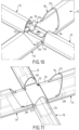
- FIGS. 10 and 11 are schematic perspective views of wave reinforcements connected at a node by connecting members according to alternative embodiments of the figure 5 .
- Elements which are identical or fulfil the same function as elements described above bear the same reference.
- the connecting member 13 illustrated on the figure 10 comprises a sleeve 25 as described with respect to the figure 5 .
- this sleeve 25 comprises a central portion 27 separating two ends 28 of said plate 24 housed in the soles 15 of two successive first wave reinforcements 11.
- a plate 33 is fixed on the central portion 27 of the sleeve 25. This plate 33 is fixed in a non-through manner on the sleeve 25. so as not to cause the sleeve 25 to protrude towards the thermal insulation barrier 2.
- the plate 33 carries two tabs 34 which each project laterally from the sleeve 25.
- the tabs 34 are each housed in the hollow portion of a second wave reinforcement 12.
- Each leg 34 is preferably elastic.
- these elastic tabs 34 are formed by a bent end of the plate 33.
- the elastic tabs 34 are shaped to exert on the second wave reinforcements 12 in which they are inserted a holding force in the direction of the thermally insulating barrier 2.
- these elastic tabs 34 advantageously make it possible to hold in position on the thermal insulation barrier 2 the second wave reinforcements 12 in which they are inserted.
- first wave reinforcements 11 and the second wave reinforcements each have a sole 15 and a reinforcement portion 16.
- the soles 15 of the second wave reinforcements 12 do not have a projecting portion 24 unlike the first wave reinforcements 11.
- the reinforcing walls 21 and the internal sails 23 of the wave reinforcements 11, 12 are not illustrated, the wave reinforcements 11, 12 illustrated on these Figures 10 and 11 which may or may not include reinforcing walls 21 and/or internal sails 23 as described above.
- the second wave reinforcements 12 comprise internal reinforcement sails as in the figure 3 and the legs 34 have an end clipped to said internal sails of the second wave reinforcements 12.
- the hollow portion of the second wave reinforcements has a lug onto which the end of the leg 34 is clipped.
- the embodiment illustrated on the figure 11 differs from the one illustrated on the figure 10 in that the legs 34 are integrated into the sleeve 25.
- the connecting member 13 has the shape of a cross comprising four legs, two opposite legs 28 being housed in the sole 15 of the first wave reinforcements 11 and two opposite legs 34 being housed in the soles 15 of the second wave reinforcements 12.
- the connecting member 13 illustrated in the figure 11 is similar to a solid or hollow sleeve 25, the central portion 27 of which develops laterally to form the legs 34 housed in the soles 15 of the second wave reinforcements 12.
- the legs 34 of the connecting member 13 can be inserted into the soles 15 of the second wave reinforcements 12 over a distance of 2 to 3 cm, or even, preferably, over a distance greater than 4 cm, in particular 4 to 6 cm, in order to cooperate with the second wave reinforcements 12 over a length sufficient to maintain the stable alignment of said second wave reinforcements 12.
- FIGS. 12 to 14 are schematic perspective views of a sealed and thermally insulating tank wall during assembly illustrating stages of assembly of the wave reinforcements and the sealing membrane on the thermally insulating barrier.
- corrugated reinforcements 11, 12 When assembling the tank, rows of corrugated reinforcements 11, 12 are installed and held in position on the thermal insulation barrier 2 before being covered by corrugated metal plates.
- These corrugated metal plates are rectangular in shape and carry high corrugations 3 and low corrugations 4. The edges of said corrugated metal plates intersect the high corrugations 3 and the low corrugations 4 between two successive nodes of said corrugations 3, 4.
- corrugated reinforcements 11, 12 positioned under corrugations 3, 4 at the edges of corrugated metal plates are jointly covered by two successive corrugated metal plates.
- FIG 12 is partially illustrated a waterproofing membrane 1 during assembly.
- some metal plates of the waterproofing membrane 1 have already been anchored on metal inserts 35 of the thermal insulation barrier 2.
- portions 36 of the wave reinforcements 11, 12 housed under corrugations 3, 4 of metal plates already installed are partially not covered by said metal plates already installed.
- rows 37 of first wave reinforcements 11 are positioned on the thermal insulation barrier 2. These rows 37 comprise a plurality of first wave reinforcements 11 assembled together by connecting members so as to form a garland of first wave reinforcements 11.
- a first end 38 of these rows 37 of first wave reinforcements is further assembled by means of a connecting member 13 to the first wave reinforcements 11 partially covered by the metal plate already anchored on the insulation barrier.
- this first end 38 of the rows 37 is held in position on the thermal insulation barrier 2 by said metal plate already anchored on the thermal insulation barrier 2.
- a second end 39 of these rows 37 of first wave reinforcements 11 opposite the first end 38 is held in position on the thermal insulation barrier 2 by means of a fixing rail 40.
- This fixing rail 40 is temporarily fixed to the thermal insulation barrier 2 by any suitable means, for example by means of screws, nails or the like.
- This fixing rail 40 is for example temporarily fixed on the metal inserts 35, said metal inserts comprising for example an orifice with thread allowing cooperation with a fixing screw of the metal rail 40.
- the fixing rail 40 can be temporarily anchored on studs used for anchoring the thermal insulation barrier 2 or by means of a fixing lug sliding into the space between two insulating panels forming the thermal insulation barrier 2.
- This fixing rail 40 covers the second end 39 of each row 37 in order to hold in position on the thermal insulation barrier 2 said second end 39 of these rows 37.
- the connecting members 13 and the fixing of the ends 38, 39 of the rows 37 of first wave reinforcements 11 thus make it possible to maintain said rows 37 in position on the thermal insulation barrier 2.
- rows 41 of second wave reinforcements 12 are positioned on the thermal insulation barrier 2. These second wave reinforcements 12 are held in position on the thermal insulation barrier 2 by any suitable means, for example using the tabs 34 of the connecting members 13 described above, by double-sided Scotch® or other.
- each corrugated metal plate comprises three portions of high corrugations 3. Furthermore, the second corrugation reinforcements 12 are held in position on the thermal insulation barrier 2 by the tabs 34 of the connecting members 13 connecting the first corrugation reinforcements 11 together. Consequently, four rows 37 of first corrugation reinforcements are installed on the thermal insulation barrier 2, the fourth row 37 making it possible to ensure the fixing of the second end corrugation reinforcements 12 of the rows 41 prior to the installation of the corrugated metal plate intended to cover them.
- the corrugated metal plate of the sealing barrier is anchored on the thermal insulation barrier 2 by welding on the metal inserts 35, thus covering the rows 37, 41 of wave reinforcements 11, 12 and ensuring their fixing on the thermal insulation barrier 2.
- the fixing rail 38 can be removed and the installation of the wave reinforcements 11, 12 and the metal plates continued by repeating the steps described above.
- FIG 15 illustrates an alternative embodiment of the assembly of the waterproofing membrane.
- the wave reinforcements are not temporarily fixed to the thermal insulation barrier 2 but to the metal plates.
- first wave reinforcements 11 are installed in the high corrugations 3 of a corrugated metal plate 42. These first wave reinforcements 11 are assembled by connecting members 13.
- first half-wave reinforcements 43 are arranged at the high corrugations 3 interrupted by the edges of the metal plate 42.
- retaining clips 44 are arranged on the edges of said metal plate 42. These retaining clips 44 comprise a portion arranged on the internal face of the metal plate 42 and a portion housed in the reinforcement portion 16 of the first half-wave reinforcement 43, as illustrated in FIG. figure 15 .
- the second wave reinforcements 12 are installed in the low corrugations 4 of the metal plate 42 and half second wave reinforcements 45 are installed in the portions of low corrugations interrupted at the edges of the metal plate 42.
- the second wave reinforcements 12 and these half second wave reinforcements 45 are held in the low corrugations 4 by cooperation with the connecting members 13 between the first wave reinforcements 11 and holding clips (not shown) similar to the holding clips 44.
- the wave reinforcements 11, 12, 43, 45 are held in position in the metal plate 42 and form a solid assembly.
- This assembly is positioned on the thermal insulation barrier 2 then, after positioning, the holding clips are removed to allow the fixing by welding of the metal plates 42 on the metal inserts 35 of the thermal insulation barrier.
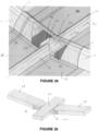
- FIG. 17 to 19 illustrate wave reinforcements connected at a node by a connecting member according to an alternative embodiment.
- elements identical to or fulfilling the same functions as elements described above bear the same reference numbers.
- This variant embodiment differs from the variants described above in that the first wave reinforcements 11 housed under the longitudinal portions 6 of the high corrugations 3 do not have a projecting portion 24.
- the sole 15 and the reinforcement portion 16 of the first wave reinforcements 11 jointly form an end face 46 of the wave reinforcement 11. This end face 46 is opposite the node 5 in which the connecting member 13 is housed, the node 5 not being illustrated in the figure. figure 17 for readability reasons.
- the end face 46 is beveled.
- the sole 15 and the reinforcement portion 16 are beveled so that the end face 46 is located in an inclined plane corresponding substantially to the inclination of the lateral constriction at the node 5.
- this end face 46 approaches as close as possible to the node 5 to optimize the support of the high corrugation 3.
- Such first wave reinforcements 11 are simple to manufacture and do not require any particular machining of the reinforcement portion 16 to produce the protruding portion 24.
- the projecting portion 24 is, in this embodiment, replaced by an added spacer 47.
- This added spacer 47 makes it possible to support the lower part of the upper corrugation 3 like the projecting portion 24 described above.
- the added spacer 47 has, for example, a structure similar to the projecting portion 24, that is to say a structure similar to the structure of the sole 15.
- the added spacer 47 is hollow and has a lower wall 48, two side walls 49, an upper wall 50 and reinforcing walls 51.
- the added spacer 47 has a face 61 complementary to the end face 46 of the wave reinforcement 11, that is to say beveled according to a bevel opposite to the bevel of the face 46.
- the different walls 48, 49, 50, 51 of the added spacer 47 extend the corresponding walls 18, 19, 20, 21 of the sole 15 in the node 5.
- the added spacer 47 extends the sole 15 of the first wave reinforcement 11 and is housed in the node 5 in a manner similar to a projecting portion 24 as described above.
- the connecting member 13 as illustrated in the figure 19 has a cross shape.
- the connecting member comprises a sleeve 25 forming two first opposite legs 28. As illustrated in the figure 17 , these first legs 28 pass through the added spacers 47 and are housed in the soles 15 of the first wave reinforcements 11 joining at the node 5. Second legs 34 allowing the second wave reinforcements 12 to be held. These second legs 34 are integrated into the sleeve 25 and project laterally from said sleeve 25 so as to be housed in the soles 15 of said second wave reinforcements 12 at the node 5, as illustrated in the figure 17 .
- the first legs 28 of the connecting member 13 illustrated in the figure 19 have an orifice 52.
- the added spacer 47 as illustrated in the figure 18 has two orifices 62. These orifices 52 and 62 allow the attachment of the spacer 47 to the connecting member 13.
- the spacers 47 can be attached in numerous ways. In the example illustrated in the figures 17 to 19 , the added spacers 47 are fixed to the connecting member 13 by riveting using rivets 53. In an embodiment not illustrated, the added spacers 47 are fixed to the connecting member 13 by screwing, by welding or by any other suitable means.
- the added spacers 47 make it possible to limit the sliding of the first wave reinforcements 11 under the high corrugations 3.
- these added spacers block the movement of the first wave reinforcements 44 in the direction of the node 5, thus preventing the end faces 46 of said first wave reinforcements 11 from coming into contact with the sealing membrane 1 at the node 5. This absence of contact makes it possible to avoid damage to the sealing membrane 1 at the nodes 5.
- such added spacers 47 fulfill the role of a stop for blocking the position of the first wave reinforcements 11 and guarantee the correct positioning of said first wave reinforcements 11 on the thermally insulating barrier 2 during the assembly of the sealing membrane 1 on the thermally insulating barrier 2.
- This stop function is particularly useful in the case of tank walls having a vertical component, preventing the first wave reinforcements 11 from moving under the effect of gravity.
- the added spacers 47 can be fixed to the connecting member 13 in prefabrication.
- connecting members 13 on which the added spacers 47 are previously fixed are positioned on the thermally insulating barrier 2 and the first wave reinforcements 11 are positioned on said thermally insulating barrier 2 by inserting into the sole 15 of said first wave reinforcements 11 the portions of tabs 28 projecting from the added spacer 47.
- the installation of the first wave reinforcements 11 intended to reinforce the high corrugations 3 of the last metal plate installed to finalize the assembly of the waterproofing membrane 1 is done with connecting members 13 on which the added spacer 47 is not previously fixed.
- the added spacers 47 are mounted on the first legs 28 of the corresponding connecting members 13 without being fixed. Said connecting members 13 are positioned on the thermally insulating barrier 2. The added spacers are then slid along the first legs 28 to allow the positioning of the first wave reinforcements 11 so as to adapt the position of said first wave reinforcements 11 to the construction constraints generated by the portions of the waterproofing membrane 1 already installed. The added spacers are then brought back into contact with said first wave reinforcements 11 and fixed on the connecting member 13.
- the first legs 28 of the connecting member 13 have a shoulder 54 forming a change in section of said first legs 28.
- the first legs 28 have a first portion 55 whose width is greater than the width of the housing 20 of the soles 15 of the first wave reinforcements 11 and a second portion 56 whose width is less, preferably slightly less, than the width of the housing 20.
- the shoulder 54 forms a stop surface limiting the insertion of the first legs 28 into the housing 20.
- the first legs 28 are inserted into the housings 20 of the soles 15 of the first wave reinforcements 11 until the shoulders 54 come into abutment against the end face 46 of said first wave reinforcements 11.
- FIG 22 illustrates a lattice 56 of wave reinforcements 11, 12, 43, 45 according to an alternative embodiment of the figure 15 .
- This variant is distinguished from that illustrated on the figure 15 in that, for mounting the wave reinforcements 11, 12, 43, 45 on the thermally insulating barrier 2, the metal plate 42 is replaced by a mounting frame 57.
- This mounting frame 57 illustrated schematically in the figure 22 comprises protrusions 58 housed in the half-wave reinforcements 43 and 45. These protrusions 58 allow the half-wave reinforcements 43 and 45 to be held in place in a manner similar to the retaining clips 44 so as to hold together the lattice 56 formed by the various wave reinforcements 11, 12, the half-wave reinforcements 43, 45, the connecting members 13 and the added spacers 47.
- the wave reinforcements 11, 12, 43, 45 can be positioned on the thermally insulating barrier 2 in blocks, each block consisting of a lattice 56 onto which a corrugated metal plate 42 of the sealing membrane 1 is subsequently added.
- FIG 23 illustrates a half-wave reinforcement 43 in a bottom view according to one embodiment.
- a half-wave reinforcement 43 located under a high corrugation 3 is illustrated, the description below applying by analogy to the half-wave reinforcements 45 located under the low corrugations 4.
- the sole 15 of the half-wave reinforcements 43 is at least partially open on the lower face of said half-wave reinforcements 43.
- the sole 15 of these half-wave reinforcements 43 has an end opposite the connecting member 13 whose lower wall 17 does not extend to the edge opposite said connecting member 13.
- said half-wave reinforcements 43 form an open housing 59 in which is housed a connecting sleeve 60 intended to connect two adjacent half-wave reinforcements 43 belonging to two adjacent trellises 56.
- This open housing 59 is thus delimited by the upper wall 19 and the reinforcing walls 21 of the sole 15 of the half-wave reinforcement 43.
- the connecting sleeve 60 has a shape complementary to the shape of the open housing 59, for example a parallelepiped shape.
- a sleeve 60 is inserted into the open housing 59 of each of the half-wave reinforcements 43 of said first lattice 56.
- the half-wave reinforcements 43 can be positioned directly by housing the sleeves 60 previously installed on the thermally insulating barrier 2 in the open housings 59 of the half-wave reinforcements 43 of this second lattice 56.
- Such connecting sleeves 60 make it possible to ensure the continuity of the wave reinforcements under the corrugations 3, 4.
- the open housings 59 may have a length greater than the length of a half connecting sleeve 60 so as to provide a positioning clearance of the connecting sleeves 60 in the open housings 59.
- Such positioning clearances make it possible to compensate for any assembly clearances of the metal plates of the waterproofing membrane, in particular when positioning the last metal plate of the waterproofing membrane 1.
- Such half-wave reinforcements 43, 45 assembled by connecting sleeves 60 further offer greater flexibility for possible repairs to the waterproofing membrane and/or the wave reinforcements 11, 12, 43, 45, only the damaged portion having to be removed for the repair.
- only one of the two half-wave reinforcements 43 or 45 assembled by a connecting sleeve 60 has the open housing 59, said connecting sleeve being slid into the other half-wave reinforcement of said pair.
- FIGS 24 and 25 are cross-sectional views of wave reinforcements according to variant embodiments.
- identical elements or those fulfilling the same function bear the same references.
- the sole 15 of the first wave reinforcement 11 does not have an upper wall 19.
- the housing 20 is open on the top, said housing being delimited by the side walls 18 and the lower wall 17.
- first wave reinforcements 11 comprise two internal sails 23 as described above with regard to the figures 4 , 7 Or 9 .
- An internal vertical wall 64 projects vertically from an intersection 65 between the internal sails 23 towards the lower wall 17.
- a lower face 63 of this internal vertical wall 64 is flat and parallel to the lower wall 17. This lower face 63 delimits, jointly with the lower wall 17 and the side walls 18, the housing 20 in which the end 28 of the connecting member 13 is housed.
- the connecting member 13 is a connecting member 13 as described above with respect to the Figures 20 and 21 .
- the ends 28 of this connecting member 13 pass through added spacers 47 as described with respect to the Figures 17 and 18 , the shoulders 54 being supported against said added spacers 47.
- These added spacers are further associated with first and second wave reinforcements 11, 12 as described with respect to the Figures 24 and 25 .
- the ends 28 and the legs 34 of the connecting member are housed in the soles 15 of the corresponding wave reinforcements 11, 12 so that the lower faces 63 of the internal vertical walls 64 are in contact with the upper face of said ends 28 and legs 34.
- FIG. 27 illustrates a wave reinforcement 11, 12 according to an alternative embodiment.
- elements identical to or fulfilling the same function as elements described above bear the same reference.
- the description below with regard to the Figures 27 and 28 applies indifferently to the first wave reinforcements 11 and/or to the second wave reinforcements 12.
- the upper wall of the sole 15 is not continuous between the lateral faces 18 of said sole 15. More particularly, this upper wall is formed of two lateral portions 66. Each of these lateral portions 66 develops parallel to the lower wall 17. These lateral portions 66 develop from a respective lateral wall 18 in the direction of the other lateral wall 18.
- the housing 20 of the sole 15 of this variant embodiment is open on the top, that is to say on the reinforcement portion 16.
- the lateral portions 66 each have a lower face 67 facing the lower wall 17, said lower faces 67 jointly delimiting with the lateral walls 18 and the lower wall 17 the housing 20 in which the end 28 or the tab 34 is housed.
- the housing 20 thus has a flat section extending parallel to the lower wall 17, that is to say having a width dimension greater than its thickness dimension, allowing cooperation with the end 28 or the tab 34 having a similar section and capable of transmitting the lateral stresses between the connecting member 13 and the wave reinforcement 11, 12.
- a connecting member 13 offers a rigidity which securely maintains the alignment between two successive wave reinforcements 11, 12 housed under a corrugation 3, 4 and assembled by said connecting member 13.
- the wave reinforcement 11, 12 in this variant comprises two internal webs 23 as described above.
- Each internal web 23 develops between a respective lateral portion 66 and the internal face of the reinforcement portion 22. More particularly, each internal web 23 develops from an end 68 of a respective lateral portion 66, said end 68 being opposite the lateral wall 18 from which said lateral portion 66 develops, in the direction of the internal face of the wall 22 of the opposite reinforcement portion 16, that is to say extending the lateral wall 18 opposite the lateral wall 18 from which said lateral portion 66 develops.
- These two internal webs 23 intersect substantially at the center of the reinforcement portion 16.
- the sole 15 has lower recesses 69 and upper recesses 82.
- the lower recesses 69 develop along the thickness direction of the sole 15 and are hollowed out in the lower wall 17 at the junctions between the lower wall 17 and the side walls 18.
- the upper recesses 82 develop along the thickness direction of the sole 15 and are formed in the side portions 66 at the junctions between said side portions 66 and the side walls 18.
- Such recesses 69, 82 make it possible to achieve a precise adjustment which is limited to the assembly clearances between the end 28 or the tab 34 and the surfaces delimiting the housing 20.
- the junction zones between the side walls 18 and on the one hand the lower wall 17 and, on the other hand, the side portions 66 do not have a curved portion which could clutter the housing 20 and interfere with the end 28 or the tab 34 when inserting said end 28 or tab 34 into the housing 20.
- the embodiment illustrated on the figure 28 differs from the embodiment illustrated in the figure 27 in that the recesses 69, 82 are hollowed out in the side walls 18 and therefore develop in a width direction of the sole 15.
- these recesses 69, 82 fulfill the same function as those described above with regard to the figure 27 avoiding the presence of curved corner areas for example in the case of wave reinforcements 11, 12 produced by extrusion or molding.
- FIGS. 29 and 30 illustrate an alternative embodiment in which the tank wall has two sides forming an angle between them, for example an angle of 167°.
- Elements which are identical or fulfil the same function as elements described above bear the same reference.
- undulations develop perpendicular to an edge 83 formed between a first panel 84 of the tank wall and a second panel 85 of said tank wall. Furthermore, undulations develop parallel to said edge 83. More particularly, in the example illustrated in the figure 29 , a corrugation develops along the edge 83 and covers said edge 83. In the example illustrated in these figures, the high corrugations 3 develop perpendicular to the edge 83 and a low corrugation 4 covers the edge 83, the description below applying by analogy to an inverse situation.
- a node 5 is therefore formed at the edge 83.
- a high corrugation 3 is continuous between the first section 84 and the second section 85 of the wall.
- the node 5 does not have a fold 7 and the longitudinal portions 6 of the corrugation 11 retain a substantially continuous section up to the plane of intersection between the sections 84, 85.
- this node cannot be crossed by a first wave reinforcement 11. Therefore, as for the nodes 5 described above, it is necessary to use a connecting member 13 to ensure continuity of the alignment between the wave reinforcements 11.
- This high corrugation 3 therefore has longitudinal portions 6 developing in a first longitudinal direction parallel to the first section 84 and perpendicular to the edge 83 and longitudinal portions 6 developing parallel to the second section 85 and perpendicular to the edge 83.
- Such a high corrugation 3 may, as explained above, be subject to asymmetrical constraints on either side of the node 5 covering the edge 83. It is therefore appropriate to ensure the alignment of the wave reinforcements 11 located on the two sides 84, 85 on either side of the node 5, that is to say to ensure that the wave reinforcement 11 located on the first side 84 and the wave reinforcement 11 located on the second side 85 maintain a longitudinal direction included in the same plane perpendicular to the edge 83.
- the connecting member 13 differs from the connecting member described above with regard to, for example, the figures 11 , 17 19 to 21 Or 26 in that the ends 28 form an angle with the central portion 27 of said connecting member 13.
- the central portion 27 is planar and has a rectangular section.
- a first end 28 extends from a first edge 86 of the central section 27 at an angle corresponding to half the angle between the two wall sections 84, 85.
- a second end 28 extends from a second edge 87 of the central section 27, opposite the first edge 86, with an angle corresponding to half the angle between the two wall sections 84, 85.
- the ends 28 each extend from the planar central portion 27 and have between them an angle corresponding to the angle between the two wall sections 84, 85.
- the first end 28 develops parallel to the first section 84 and the second end 28 develops parallel to the second section 85.
- the first end 28 is inserted into the housing 20 formed by the hollow sole 15 of the wave reinforcement 11 located in the longitudinal portion 6 of the corrugation forming the node 5 and located in the first section 84 and the second end 28 is inserted into the housing 20 formed by the hollow sole 15 of the wave reinforcement 11 located under the longitudinal portion 6 of the corrugation forming the node 5 located in the second section 85 of the wall.
- the ends 28 of this connecting member 13 are fitted together with a simple assembly clearance in order to ensure good cooperation between said ends 28 and the sole 15 and thus maintain alignment of the wave reinforcements 11 with respect to the lateral constraints.
- the technique described above for producing a sealed and thermally insulating tank can be used in different types of tanks, for example to constitute the primary sealing membrane of an LNG tank in a land-based installation or in a floating structure such as an LNG carrier or other.
- a cutaway view of a LNG carrier 70 shows a sealed and insulated tank 71 of generally prismatic shape mounted in the double hull 72 of the ship.
- the wall of the tank 71 comprises a primary sealed barrier intended to be in contact with the LNG contained in the tank, a secondary sealed barrier arranged between the primary sealed barrier and the double hull 72 of the ship, and two insulating barriers arranged respectively between the primary sealed barrier and the secondary sealed barrier and between the secondary sealed barrier and the double hull 72.
- loading/unloading pipelines 73 arranged on the upper deck of the ship can be connected, by means of appropriate connectors, to a maritime or port terminal to transfer a cargo of LNG from or to the tank 71.
- FIG 16 represents an example of a marine terminal comprising a loading and unloading station 75, a subsea pipeline 76 and a land-based installation 77.
- the loading and unloading station 75 is a fixed offshore installation comprising a mobile arm 74 and a tower 78 which supports the mobile arm 74.
- the mobile arm 74 carries a bundle of insulated flexible pipes 79 which can be connected to the loading/unloading pipelines 73.
- the orientable mobile arm 74 adapts to all sizes of LNG carriers.
- a connecting pipe, not shown, extends inside the tower 78.
- the loading and unloading station 75 allows the loading and unloading of the LNG carrier 70 from or to the onshore installation 77.
- the latter comprises liquefied gas storage tanks 80 and connecting pipes 81 connected by the subsea pipe 76 to the loading or unloading station 75.
- the subsea pipe 76 allows the transfer of the liquefied gas between the loading or unloading station 75 and the onshore installation 77 over a long distance, for example 5 km, which allows keep the LNG carrier 70 at a great distance from the coast during loading and unloading operations.
- pumps on board the ship 70 and/or pumps equipping the onshore installation 77 and/or pumps equipping the loading and unloading station 75 are used.
Landscapes
- Engineering & Computer Science (AREA)
- Mechanical Engineering (AREA)
- General Engineering & Computer Science (AREA)
- Physics & Mathematics (AREA)
- Thermal Sciences (AREA)
- Filling Or Discharging Of Gas Storage Vessels (AREA)
- Revetment (AREA)
Applications Claiming Priority (3)
| Application Number | Priority Date | Filing Date | Title |
|---|---|---|---|
| FR1850874A FR3077278B1 (fr) | 2018-02-01 | 2018-02-01 | Paroi etanche a membrane ondulee renforcee |
| FR1852568A FR3077277B1 (fr) | 2018-02-01 | 2018-03-23 | Paroi etanche a membrane ondulee renforcee |
| PCT/FR2019/050232 WO2019150054A1 (fr) | 2018-02-01 | 2019-02-01 | Paroi etanche a membrane ondulee renforcee |
Publications (3)
| Publication Number | Publication Date |
|---|---|
| EP3746377A1 EP3746377A1 (fr) | 2020-12-09 |
| EP3746377B1 true EP3746377B1 (fr) | 2024-08-14 |
| EP3746377C0 EP3746377C0 (fr) | 2024-08-14 |
Family
ID=62143344
Family Applications (1)
| Application Number | Title | Priority Date | Filing Date |
|---|---|---|---|
| EP19707444.6A Active EP3746377B1 (fr) | 2018-02-01 | 2019-02-01 | Paroi de cuve étanche, procédé de montage de paroi de cuve étanche, navire, procédé de chargement/déchargement d'un navire, système de transfert pour un produit liquide froid |
Country Status (12)
| Country | Link |
|---|---|
| US (1) | US11913604B2 (https=) |
| EP (1) | EP3746377B1 (https=) |
| JP (1) | JP7286662B2 (https=) |
| KR (1) | KR102502222B1 (https=) |
| CN (1) | CN111971236B (https=) |
| ES (1) | ES2991975T3 (https=) |
| FR (2) | FR3077278B1 (https=) |
| PL (1) | PL3746377T3 (https=) |
| RU (1) | RU2760804C1 (https=) |
| SA (1) | SA520412560B1 (https=) |
| SG (1) | SG11202007296RA (https=) |
| WO (1) | WO2019150054A1 (https=) |
Families Citing this family (13)
| Publication number | Priority date | Publication date | Assignee | Title |
|---|---|---|---|---|
| FR3101337B1 (fr) * | 2019-09-26 | 2021-12-10 | Gaztransport Et Technigaz | Procédé de réparation d’une paroi de cuve de transport et/ou de stockage de gaz naturel liquéfié. |
| FR3112764B1 (fr) * | 2020-07-24 | 2022-08-05 | Gaztransport Et Technigaz | Système d’empilement de membranes d’une cuve étanche et thermiquement isolante |
| FR3120556B1 (fr) * | 2021-03-12 | 2023-11-24 | Gaztransport Et Technigaz | Procédé pour assembler une membrane d’étanchéité d’une paroi d’une cuve |
| FR3122240B1 (fr) * | 2021-04-22 | 2024-01-12 | Gaztransport Et Technigaz | Dispositif de maintien d’un maillage de renforts d’onde. |
| CN115465476B (zh) * | 2022-07-28 | 2024-06-25 | 上海空间推进研究所 | 用于管理推进剂的挤压隔离装置 |
| CN116123436B (zh) * | 2023-01-16 | 2024-02-09 | 宇欧围护技术(上海)有限公司 | 双拱直角膜和双拱多坡峰直角金属延展膜 |
| FR3149067B1 (fr) | 2023-05-23 | 2025-04-18 | Gaztransport Et Technigaz | Panneau isolant convenant pour la fabrication d’une paroi de cuve et muni d’un instrument de mesure d’efforts |
| CN116605357B (zh) * | 2023-07-20 | 2023-10-24 | 中太(苏州)氢能源科技有限公司 | 一种用于液化气体储存舱内壁的部件 |
| CN116753452B (zh) * | 2023-08-08 | 2023-11-24 | 中太能源科技(上海)有限公司 | 液化天然气储存容器 |
| CN117739268B (zh) * | 2023-11-30 | 2026-03-31 | 沪东中华造船(集团)有限公司 | 一种用于存储和运输液化气的密封膜及密封罐 |
| FR3160752A1 (fr) * | 2024-04-02 | 2025-10-03 | Gaztransport Et Technigaz | Paroi étanche et thermiquement isolante |
| CN119239825B (zh) * | 2024-09-05 | 2026-03-20 | 沪东中华造船(集团)有限公司 | 一种lng船液货围护系统波纹单元及波纹板 |
| CN121654877A (zh) * | 2026-02-06 | 2026-03-13 | 中太能源科技(上海)有限公司 | 一种波纹板填充结构及其安装方法 |
Family Cites Families (23)
| Publication number | Priority date | Publication date | Assignee | Title |
|---|---|---|---|---|
| GB547578A (en) * | 1941-05-01 | 1942-09-02 | Motherwell Bridge & Engineerin | Improvements in or relating to storage tanks |
| FR2683786B1 (fr) * | 1991-11-20 | 1994-02-18 | Gaz Transport | Cuve etanche et thermiquement isolante perfectionnee, integree a la structure porteuse d'un navire. |
| CN2304628Y (zh) * | 1997-04-04 | 1999-01-20 | 蔡洪文 | 新型组合式储罐内浮顶 |
| FR2781557B1 (fr) * | 1998-07-24 | 2000-09-15 | Gaz Transport & Technigaz | Perfectionnement pour une cuve etanche et thermiquement isolante a panneaux prefabriques |
| FR2861060B1 (fr) | 2003-10-16 | 2006-01-06 | Gaz Transport & Technigaz | Structure de paroi etanche et cuve munie d'une telle structure |
| US20110186580A1 (en) | 2008-03-03 | 2011-08-04 | Samsung Heavy Ind. Co., Ltd. | Reinforcing member for corrugated membrane of lng cargo tank, membrane assembly having the reinforcing member and method for constructing the same |
| AU2012201046B2 (en) * | 2008-10-08 | 2012-09-06 | Gaztransport Et Technigaz | Vessel with a reinforced corrugated membrane |
| FR2936784B1 (fr) | 2008-10-08 | 2010-10-08 | Gaztransp Et Technigaz | Cuve a membrane ondulee renforcee |
| FR2963818B1 (fr) * | 2010-08-11 | 2014-01-03 | Gaztransp Et Technigaz | Structure de paroi etanche |
| FR2968284B1 (fr) * | 2010-12-01 | 2013-12-20 | Gaztransp Et Technigaz | Barriere d'etancheite pour une paroi de cuve |
| FR2987099B1 (fr) * | 2012-02-20 | 2015-04-17 | Gaztransp Et Technigaz | Cuve etanche et thermiquement isolante comportant une piece d'angle |
| KR101349881B1 (ko) * | 2012-06-13 | 2014-01-16 | 삼성중공업 주식회사 | 액화천연가스 저장탱크의 1차 방벽용 보강 부재 고정 장치 |
| FR3001945B1 (fr) * | 2013-02-14 | 2017-04-28 | Gaztransport Et Technigaz | Paroi etanche et thermiquement isolante pour cuve de stockage de fluide |
| FR3004234B1 (fr) * | 2013-04-09 | 2016-07-29 | Gaztransport Et Technigaz | Cuve etanche et isolante ayant une barriere d'etancheite susceptible localement d'un glissement par rapport a la barriere isolante |
| FR3004507B1 (fr) * | 2013-04-11 | 2019-04-26 | Gaztransport Et Technigaz | Decouplage des ondulations d'une barriere etanche |
| CN203442474U (zh) * | 2013-07-30 | 2014-02-19 | 中国国际海运集装箱(集团)股份有限公司 | 用于低温罐车外罐的封闭装置及低温罐车 |
| KR101571426B1 (ko) | 2014-02-21 | 2015-11-24 | 삼성중공업 주식회사 | 1차방벽용 보강유닛 |
| FR3022971B1 (fr) * | 2014-06-25 | 2017-03-31 | Gaztransport Et Technigaz | Cuve etanche et isolante et son procede de fabrication |
| FR3023257B1 (fr) * | 2014-07-04 | 2017-12-29 | Gaztransport Et Technigaz | Cuve etanche et isolante disposee dans une double coque flottante |
| CN107073540B (zh) * | 2014-09-02 | 2019-04-05 | 气体运输技术公司 | 用于在金属板中同时形成多个波纹的折弯装置及该装置的使用方法 |
| FR3026459B1 (fr) * | 2014-09-26 | 2017-06-09 | Gaztransport Et Technigaz | Cuve etanche et isolante comportant un element de pontage entre les panneaux de la barriere isolante secondaire |
| FR3038690B1 (fr) | 2015-07-06 | 2018-01-05 | Gaztransport Et Technigaz | Cuve etanche et thermiquement isolante ayant une membrane d'etancheite secondaire equipee d'un arrangement d'angle a toles metalliques ondulees |
| FR3039248B1 (fr) * | 2015-07-24 | 2017-08-18 | Gaztransport Et Technigaz | Cuve etanche et thermiquement isolante munie d'une piece de renfort |
-
2018
- 2018-02-01 FR FR1850874A patent/FR3077278B1/fr active Active
- 2018-03-23 FR FR1852568A patent/FR3077277B1/fr active Active
-
2019
- 2019-02-01 CN CN201980024420.4A patent/CN111971236B/zh active Active
- 2019-02-01 US US16/965,577 patent/US11913604B2/en active Active
- 2019-02-01 WO PCT/FR2019/050232 patent/WO2019150054A1/fr not_active Ceased
- 2019-02-01 JP JP2020541666A patent/JP7286662B2/ja active Active
- 2019-02-01 SG SG11202007296RA patent/SG11202007296RA/en unknown
- 2019-02-01 EP EP19707444.6A patent/EP3746377B1/fr active Active
- 2019-02-01 KR KR1020207023217A patent/KR102502222B1/ko active Active
- 2019-02-01 ES ES19707444T patent/ES2991975T3/es active Active
- 2019-02-01 PL PL19707444.6T patent/PL3746377T3/pl unknown
- 2019-02-01 RU RU2020125090A patent/RU2760804C1/ru active
-
2020
- 2020-07-30 SA SA520412560A patent/SA520412560B1/ar unknown
Also Published As
| Publication number | Publication date |
|---|---|
| KR102502222B1 (ko) | 2023-02-21 |
| FR3077278B1 (fr) | 2020-02-07 |
| SA520412560B1 (ar) | 2022-12-08 |
| WO2019150054A1 (fr) | 2019-08-08 |
| JP7286662B2 (ja) | 2023-06-05 |
| FR3077277B1 (fr) | 2020-01-24 |
| RU2760804C1 (ru) | 2021-11-30 |
| US20210071817A1 (en) | 2021-03-11 |
| FR3077278A1 (fr) | 2019-08-02 |
| JP2021514334A (ja) | 2021-06-10 |
| EP3746377A1 (fr) | 2020-12-09 |
| ES2991975T3 (es) | 2024-12-05 |
| FR3077277A1 (fr) | 2019-08-02 |
| SG11202007296RA (en) | 2020-08-28 |
| CN111971236B (zh) | 2022-08-05 |
| US11913604B2 (en) | 2024-02-27 |
| EP3746377C0 (fr) | 2024-08-14 |
| CN111971236A (zh) | 2020-11-20 |
| PL3746377T3 (pl) | 2025-01-13 |
| KR20200112879A (ko) | 2020-10-05 |
Similar Documents
| Publication | Publication Date | Title |
|---|---|---|
| EP3746377B1 (fr) | Paroi de cuve étanche, procédé de montage de paroi de cuve étanche, navire, procédé de chargement/déchargement d'un navire, système de transfert pour un produit liquide froid | |
| EP3362732B1 (fr) | Cuve étanche et thermiquement isolante | |
| EP3320256B1 (fr) | Cuve etanche et thermiquement isolante ayant une membrane d'etancheite secondaire equipee d'un arrangement d'angle a toles metalliques ondulees | |
| EP3033564B1 (fr) | Cuve etanche et thermiquement isolante comportant une piece d'angle | |
| EP3198186B1 (fr) | Cuve étanche et isolante comportant un élément de pontage entre les panneaux de la barrière isolante secondaire | |
| EP2984384B1 (fr) | Structure d'angle d'une cuve etanche et thermiquement isolante de stockage d'un fluide | |
| EP2984383B1 (fr) | Cuve etanche et thermiquement isolante de stockage d'un fluide | |
| EP3473915B1 (fr) | Cuve etanche et thermiquement isolante | |
| EP3298320A1 (fr) | Cuve etanche et thermiquement isolante munie d'une piece de renfort | |
| FR3001945A1 (fr) | Paroi etanche et thermiquement isolante pour cuve de stockage de fluide | |
| FR3084347A1 (fr) | Paroi etanche a membrane ondulee renforcee | |
| EP3425260B1 (fr) | Cuve etanche et thermiquement isolante comportant une corniere | |
| EP3425261B1 (fr) | Cuve etanche et thermiquement isolante | |
| FR3049678A1 (fr) | Bloc de bordure thermiquement isolant pour la fabrication d'une paroi de cuve | |
| WO2018024982A1 (fr) | Structure de paroi etanche | |
| WO2019102163A1 (fr) | Cuve etanche et thermiquement isolante | |
| FR3084346A1 (fr) | Paroi etanche a membrane ondulee renforcee | |
| FR3061260A1 (fr) | Cuve etanche et thermiquement isolante de stockage d'un fluide | |
| EP3821167B1 (fr) | Paroi de cuve comportant une membrane d'étanchéite présentant une ondulation ayant une portion curviligne renforcée | |
| EP3948055B1 (fr) | Installation de stockage pour gaz liquéfié | |
| FR3094452A1 (fr) | Installation de stockage pour gaz liquéfié | |
| EP3526512B1 (fr) | Cuve étanche et thermiquement isolante | |
| WO2023227551A1 (fr) | Cuve etanche et thermiquement isolante integree dans une structure porteuse |
Legal Events
| Date | Code | Title | Description |
|---|---|---|---|
| STAA | Information on the status of an ep patent application or granted ep patent |
Free format text: STATUS: UNKNOWN |
|
| STAA | Information on the status of an ep patent application or granted ep patent |
Free format text: STATUS: THE INTERNATIONAL PUBLICATION HAS BEEN MADE |
|
| PUAI | Public reference made under article 153(3) epc to a published international application that has entered the european phase |
Free format text: ORIGINAL CODE: 0009012 |
|
| STAA | Information on the status of an ep patent application or granted ep patent |
Free format text: STATUS: REQUEST FOR EXAMINATION WAS MADE |
|
| 17P | Request for examination filed |
Effective date: 20200824 |
|
| AK | Designated contracting states |
Kind code of ref document: A1 Designated state(s): AL AT BE BG CH CY CZ DE DK EE ES FI FR GB GR HR HU IE IS IT LI LT LU LV MC MK MT NL NO PL PT RO RS SE SI SK SM TR |
|
| AX | Request for extension of the european patent |
Extension state: BA ME |
|
| DAV | Request for validation of the european patent (deleted) | ||
| DAX | Request for extension of the european patent (deleted) | ||
| STAA | Information on the status of an ep patent application or granted ep patent |
Free format text: STATUS: EXAMINATION IS IN PROGRESS |
|
| 17Q | First examination report despatched |
Effective date: 20220906 |
|
| REG | Reference to a national code |
Ref country code: DE Ref legal event code: R079 Free format text: PREVIOUS MAIN CLASS: B65D0090020000 Ipc: F17C0013000000 Ref document number: 602019056945 Country of ref document: DE |
|
| GRAP | Despatch of communication of intention to grant a patent |
Free format text: ORIGINAL CODE: EPIDOSNIGR1 |
|
| STAA | Information on the status of an ep patent application or granted ep patent |
Free format text: STATUS: GRANT OF PATENT IS INTENDED |
|
| RIC1 | Information provided on ipc code assigned before grant |
Ipc: B65D 90/04 20060101ALI20240308BHEP Ipc: B65D 90/02 20190101ALI20240308BHEP Ipc: F17C 13/00 20060101AFI20240308BHEP |
|
| INTG | Intention to grant announced |
Effective date: 20240328 |
|
| RIN1 | Information on inventor provided before grant (corrected) |
Inventor name: BOUGAULT, JOHAN Inventor name: BERGER, VINCENT Inventor name: DELANOE, SEBASTIEN Inventor name: PHILIPPE, ANTOINE Inventor name: BOYEAU, MARC Inventor name: SASSI, MOHAMED |
|
| GRAS | Grant fee paid |
Free format text: ORIGINAL CODE: EPIDOSNIGR3 |
|
| GRAA | (expected) grant |
Free format text: ORIGINAL CODE: 0009210 |
|
| STAA | Information on the status of an ep patent application or granted ep patent |
Free format text: STATUS: THE PATENT HAS BEEN GRANTED |
|
| AK | Designated contracting states |
Kind code of ref document: B1 Designated state(s): AL AT BE BG CH CY CZ DE DK EE ES FI FR GB GR HR HU IE IS IT LI LT LU LV MC MK MT NL NO PL PT RO RS SE SI SK SM TR |
|
| REG | Reference to a national code |
Ref country code: GB Ref legal event code: FG4D Free format text: NOT ENGLISH |
|
| REG | Reference to a national code |
Ref country code: CH Ref legal event code: EP |
|
| REG | Reference to a national code |
Ref country code: DE Ref legal event code: R096 Ref document number: 602019056945 Country of ref document: DE |
|
| REG | Reference to a national code |
Ref country code: IE Ref legal event code: FG4D Free format text: LANGUAGE OF EP DOCUMENT: FRENCH |
|
| U01 | Request for unitary effect filed |
Effective date: 20240902 |
|
| U07 | Unitary effect registered |
Designated state(s): AT BE BG DE DK EE FI FR IT LT LU LV MT NL PT RO SE SI Effective date: 20240912 |
|
| REG | Reference to a national code |
Ref country code: ES Ref legal event code: FG2A Ref document number: 2991975 Country of ref document: ES Kind code of ref document: T3 Effective date: 20241205 |
|
| PG25 | Lapsed in a contracting state [announced via postgrant information from national office to epo] |
Ref country code: GR Free format text: LAPSE BECAUSE OF FAILURE TO SUBMIT A TRANSLATION OF THE DESCRIPTION OR TO PAY THE FEE WITHIN THE PRESCRIBED TIME-LIMIT Effective date: 20241115 |
|
| PG25 | Lapsed in a contracting state [announced via postgrant information from national office to epo] |
Ref country code: IS Free format text: LAPSE BECAUSE OF FAILURE TO SUBMIT A TRANSLATION OF THE DESCRIPTION OR TO PAY THE FEE WITHIN THE PRESCRIBED TIME-LIMIT Effective date: 20241214 |
|
| PG25 | Lapsed in a contracting state [announced via postgrant information from national office to epo] |
Ref country code: HR Free format text: LAPSE BECAUSE OF FAILURE TO SUBMIT A TRANSLATION OF THE DESCRIPTION OR TO PAY THE FEE WITHIN THE PRESCRIBED TIME-LIMIT Effective date: 20240814 |
|
| PG25 | Lapsed in a contracting state [announced via postgrant information from national office to epo] |
Ref country code: RS Free format text: LAPSE BECAUSE OF FAILURE TO SUBMIT A TRANSLATION OF THE DESCRIPTION OR TO PAY THE FEE WITHIN THE PRESCRIBED TIME-LIMIT Effective date: 20241114 |
|
| PG25 | Lapsed in a contracting state [announced via postgrant information from national office to epo] |
Ref country code: RS Free format text: LAPSE BECAUSE OF FAILURE TO SUBMIT A TRANSLATION OF THE DESCRIPTION OR TO PAY THE FEE WITHIN THE PRESCRIBED TIME-LIMIT Effective date: 20241114 Ref country code: IS Free format text: LAPSE BECAUSE OF FAILURE TO SUBMIT A TRANSLATION OF THE DESCRIPTION OR TO PAY THE FEE WITHIN THE PRESCRIBED TIME-LIMIT Effective date: 20241214 Ref country code: HR Free format text: LAPSE BECAUSE OF FAILURE TO SUBMIT A TRANSLATION OF THE DESCRIPTION OR TO PAY THE FEE WITHIN THE PRESCRIBED TIME-LIMIT Effective date: 20240814 Ref country code: GR Free format text: LAPSE BECAUSE OF FAILURE TO SUBMIT A TRANSLATION OF THE DESCRIPTION OR TO PAY THE FEE WITHIN THE PRESCRIBED TIME-LIMIT Effective date: 20241115 |
|
| U20 | Renewal fee for the european patent with unitary effect paid |
Year of fee payment: 7 Effective date: 20250129 |
|
| PG25 | Lapsed in a contracting state [announced via postgrant information from national office to epo] |
Ref country code: SM Free format text: LAPSE BECAUSE OF FAILURE TO SUBMIT A TRANSLATION OF THE DESCRIPTION OR TO PAY THE FEE WITHIN THE PRESCRIBED TIME-LIMIT Effective date: 20240814 |
|
| PG25 | Lapsed in a contracting state [announced via postgrant information from national office to epo] |
Ref country code: CZ Free format text: LAPSE BECAUSE OF FAILURE TO SUBMIT A TRANSLATION OF THE DESCRIPTION OR TO PAY THE FEE WITHIN THE PRESCRIBED TIME-LIMIT Effective date: 20240814 |
|
| PG25 | Lapsed in a contracting state [announced via postgrant information from national office to epo] |
Ref country code: SK Free format text: LAPSE BECAUSE OF FAILURE TO SUBMIT A TRANSLATION OF THE DESCRIPTION OR TO PAY THE FEE WITHIN THE PRESCRIBED TIME-LIMIT Effective date: 20240814 |
|
| PLBE | No opposition filed within time limit |
Free format text: ORIGINAL CODE: 0009261 |
|
| STAA | Information on the status of an ep patent application or granted ep patent |
Free format text: STATUS: NO OPPOSITION FILED WITHIN TIME LIMIT |
|
| 26N | No opposition filed |
Effective date: 20250515 |
|
| PG25 | Lapsed in a contracting state [announced via postgrant information from national office to epo] |
Ref country code: MC Free format text: LAPSE BECAUSE OF FAILURE TO SUBMIT A TRANSLATION OF THE DESCRIPTION OR TO PAY THE FEE WITHIN THE PRESCRIBED TIME-LIMIT Effective date: 20240814 |
|
| REG | Reference to a national code |
Ref country code: CH Ref legal event code: PL |
|
| PG25 | Lapsed in a contracting state [announced via postgrant information from national office to epo] |
Ref country code: CH Free format text: LAPSE BECAUSE OF NON-PAYMENT OF DUE FEES Effective date: 20250228 |
|
| GBPC | Gb: european patent ceased through non-payment of renewal fee |
Effective date: 20250201 |
|
| PG25 | Lapsed in a contracting state [announced via postgrant information from national office to epo] |
Ref country code: GB Free format text: LAPSE BECAUSE OF NON-PAYMENT OF DUE FEES Effective date: 20250201 |
|
| PG25 | Lapsed in a contracting state [announced via postgrant information from national office to epo] |
Ref country code: IE Free format text: LAPSE BECAUSE OF NON-PAYMENT OF DUE FEES Effective date: 20250201 |
|
| U20 | Renewal fee for the european patent with unitary effect paid |
Year of fee payment: 8 Effective date: 20260121 |
|
| PGFP | Annual fee paid to national office [announced via postgrant information from national office to epo] |
Ref country code: ES Payment date: 20260309 Year of fee payment: 8 |
|
| PGFP | Annual fee paid to national office [announced via postgrant information from national office to epo] |
Ref country code: NO Payment date: 20260127 Year of fee payment: 8 |
|
| PGFP | Annual fee paid to national office [announced via postgrant information from national office to epo] |
Ref country code: TR Payment date: 20260128 Year of fee payment: 8 |
|
| PGFP | Annual fee paid to national office [announced via postgrant information from national office to epo] |
Ref country code: PL Payment date: 20260120 Year of fee payment: 8 |