EP3744111B1 - Energiebegrenzer für lautsprecherschutz - Google Patents
Energiebegrenzer für lautsprecherschutz Download PDFInfo
- Publication number
- EP3744111B1 EP3744111B1 EP19763318.3A EP19763318A EP3744111B1 EP 3744111 B1 EP3744111 B1 EP 3744111B1 EP 19763318 A EP19763318 A EP 19763318A EP 3744111 B1 EP3744111 B1 EP 3744111B1
- Authority
- EP
- European Patent Office
- Prior art keywords
- loudspeaker
- displacement
- voltage
- energy
- diaphragm
- Prior art date
- Legal status (The legal status is an assumption and is not a legal conclusion. Google has not performed a legal analysis and makes no representation as to the accuracy of the status listed.)
- Active
Links
Images


Classifications
-
- H—ELECTRICITY
- H04—ELECTRIC COMMUNICATION TECHNIQUE
- H04R—LOUDSPEAKERS, MICROPHONES, GRAMOPHONE PICK-UPS OR LIKE ACOUSTIC ELECTROMECHANICAL TRANSDUCERS; DEAF-AID SETS; PUBLIC ADDRESS SYSTEMS
- H04R3/00—Circuits for transducers, loudspeakers or microphones
- H04R3/007—Protection circuits for transducers
-
- H—ELECTRICITY
- H04—ELECTRIC COMMUNICATION TECHNIQUE
- H04R—LOUDSPEAKERS, MICROPHONES, GRAMOPHONE PICK-UPS OR LIKE ACOUSTIC ELECTROMECHANICAL TRANSDUCERS; DEAF-AID SETS; PUBLIC ADDRESS SYSTEMS
- H04R29/00—Monitoring arrangements; Testing arrangements
- H04R29/001—Monitoring arrangements; Testing arrangements for loudspeakers
-
- H—ELECTRICITY
- H04—ELECTRIC COMMUNICATION TECHNIQUE
- H04R—LOUDSPEAKERS, MICROPHONES, GRAMOPHONE PICK-UPS OR LIKE ACOUSTIC ELECTROMECHANICAL TRANSDUCERS; DEAF-AID SETS; PUBLIC ADDRESS SYSTEMS
- H04R7/00—Diaphragms for electromechanical transducers; Cones
- H04R7/02—Diaphragms for electromechanical transducers; Cones characterised by the construction
-
- H—ELECTRICITY
- H04—ELECTRIC COMMUNICATION TECHNIQUE
- H04R—LOUDSPEAKERS, MICROPHONES, GRAMOPHONE PICK-UPS OR LIKE ACOUSTIC ELECTROMECHANICAL TRANSDUCERS; DEAF-AID SETS; PUBLIC ADDRESS SYSTEMS
- H04R9/00—Transducers of moving-coil, moving-strip, or moving-wire type
- H04R9/06—Loudspeakers
-
- H—ELECTRICITY
- H04—ELECTRIC COMMUNICATION TECHNIQUE
- H04R—LOUDSPEAKERS, MICROPHONES, GRAMOPHONE PICK-UPS OR LIKE ACOUSTIC ELECTROMECHANICAL TRANSDUCERS; DEAF-AID SETS; PUBLIC ADDRESS SYSTEMS
- H04R2499/00—Aspects covered by H04R or H04S not otherwise provided for in their subgroups
- H04R2499/10—General applications
- H04R2499/11—Transducers incorporated or for use in hand-held devices, e.g. mobile phones, PDA's, camera's
-
- H—ELECTRICITY
- H04—ELECTRIC COMMUNICATION TECHNIQUE
- H04R—LOUDSPEAKERS, MICROPHONES, GRAMOPHONE PICK-UPS OR LIKE ACOUSTIC ELECTROMECHANICAL TRANSDUCERS; DEAF-AID SETS; PUBLIC ADDRESS SYSTEMS
- H04R3/00—Circuits for transducers, loudspeakers or microphones
- H04R3/04—Circuits for transducers, loudspeakers or microphones for correcting frequency response
Definitions
- One or more embodiments relate generally to loudspeakers, and in particular, a method and system for limiting energy stored in a loudspeaker.
- a loudspeaker produces sound when connected to an integrated amplifier, a television (TV) set, a radio, a music player, an electronic sound producing device (e.g., a smartphone, a computer), a video player, etc..
- Technologies for controlling the input signal of a loudspeaker are provided for example in publication US 2017/0280240 A1 , which discloses adaptive filters for estimating a response of an electrical characteristic of a loudspeaker based on an error level between a first and a second parameter of the loudspeaker and adding a time delay between the first and second parameters so that the filter could capture a truncated non-causality of the parameters, and publication DE 10 2012 020 271 A1 , which relates to methods for controlling a transducer using a controller for producing a desired linear or non-linear transmission behavior of the transducer and for protecting the transducer from electrical, thermal, or mechanical overload when the signal amplitude is high.
- One or more embodiments relate generally to loudspeakers, and in particular, a method and system for limiting energy stored in a loudspeaker.
- One embodiment provides a method comprising determining a potential energy in a loudspeaker, a kinetic energy in the loudspeaker, and an electrical energy in the loudspeaker based on a physical model of the loudspeaker. The method further comprises determining a total energy stored in the loudspeaker based on the potential energy, the kinetic energy, and the electrical energy.
- the method further comprises determining a maximum potential displacement of a diaphragm of a speaker driver of the loudspeaker based on the total energy, and limiting the total energy stored in the loudspeaker by attenuating a source signal for reproduction via the loudspeaker. An actual displacement of the diaphragm during the reproduction of the source signal is controlled based on the attenuated source signal.
- the system comprises a voltage source amplifier connected to the loudspeaker and a limiter connected to the voltage source amplifier.
- the limiter is configured to determine a potential energy in the loudspeaker, a kinetic energy in the loudspeaker, and an electrical energy in the loudspeaker based on a physical model of the loudspeaker.
- the limiter is further configured to determine a total energy stored in the loudspeaker based on the potential energy, the kinetic energy, and the electrical energy.
- the limiter is further configured to determine a maximum potential displacement of a diaphragm of a speaker driver of the loudspeaker based on the total energy, and limit the total energy stored in the loudspeaker by attenuating a voltage of a source signal for reproduction via the loudspeaker.
- the voltage source amplifier outputs the attenuated voltage to drive the speaker driver. An actual displacement of the diaphragm during the reproduction of the source signal is controlled based on the attenuated voltage.
- One embodiment provides a loudspeaker device comprising a speaker driver including a diaphragm, a voltage source amplifier connected to the speaker driver, and a limiter connected to the voltage source amplifier.
- the limiter is configured to determine a potential energy in the loudspeaker, a kinetic energy in the loudspeaker, and an electrical energy in the loudspeaker based on a physical model of the loudspeaker.
- the limiter is further configured to determine a total energy stored in the loudspeaker based on the potential energy, the kinetic energy, and the electrical energy.
- the limiter is further configured to determine a maximum potential displacement of a diaphragm of a speaker driver of the loudspeaker based on the total energy, and limit the total energy stored in the loudspeaker by attenuating a voltage of a source signal for reproduction via the loudspeaker.
- the voltage source amplifier outputs the attenuated voltage to drive the speaker driver. An actual displacement of the diaphragm during the reproduction of the source signal is controlled based on the attenuated voltage.
- the terms “loudspeaker”, “loudspeaker device” and “loudspeaker system” may be used interchangeably in this specification.
- a conventional loudspeaker is nonlinear by design and produces harmonics, intermodulation components, and modulation noise.
- Nonlinear audio distortion i.e., audible distortion
- sound quality of audio produced by the loudspeaker e.g., audio quality and speech intelligibility
- industrial design constraints often require loudspeaker systems to be smaller-sized for portability and compactness.
- Such design constraints however, trade size and portability for sound quality, resulting in increased audio distortion.
- an anti-distortion system for reducing/removing audio distortion is needed, in particular for obtaining a more pronounced/bigger bass sound from smaller-sized loudspeaker systems.
- a loudspeaker device includes at least one speaker driver for reproducing sound.
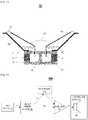
- FIG. 1 illustrates a cross section of an example speaker driver 55.
- the speaker driver 55 comprises one or more moving components, such as a diaphragm 56 (e.g., a cone-shaped diaphragm), a driver voice coil 57, a former 64, and a protective cap 68 (e.g., a dome-shaped dust cap).
- the speaker driver 55 further comprises one or more of the following components: (1) a surround roll 58 (e.g., suspension roll), (2) a basket 59, (3) a top plate 61, (4) a magnet 62, (5) a bottom plate 63, (6) a pole piece 66, and (7) a spider 67.
- FIG. 2 illustrates an example loudspeaker system 100, in accordance with an embodiment.
- the loudspeaker system 100 comprises a loudspeaker device 60 including a speaker driver 65 for reproducing sound.
- the loudspeaker device 60 may be any type of loudspeaker device such as, but not limited to, a sealed-box loudspeaker, a vented-box loudspeaker, a passive-radiator loudspeaker, a loudspeaker array, etc.
- the speaker driver 65 may be any type of speaker driver such as, but not limited to, a forward-facing speaker driver, an upward-facing speaker driver, a downward-facing speaker driver, etc.
- the speaker driver 55 in FIG. 1 is an example implementation of the speaker driver 65.
- the speaker driver 65 comprises one or more moving components, such as a diaphragm 56 ( FIG. 1 ) and a driver voice coil 57 ( FIG. 1 ).
- the loudspeaker system 100 comprises an energy limiter system 200 configured to monitor and control energy stored in the loudspeaker device 60 to predict and limit and/or compress displacement of the one or more moving components during audio reproduction.
- the system 200 is configured to receive a source signal (e.g., an input signal such as an input audio signal) from an input source 10 for audio reproduction via the loudspeaker device 60.
- the energy limiter system 200 is configured to receive a source signal from different types of input sources 10.
- Examples of different types of input sources 10 include, but are not limited to, a mobile electronic device (e.g., a smartphone, a laptop, a tablet, etc.), a content playback device (e.g., a television, a radio, a computer, a music player such as a CD player, a video player such as a DVD player, a turntable, etc.), or an audio receiver, etc.
- a mobile electronic device e.g., a smartphone, a laptop, a tablet, etc.
- a content playback device e.g., a television, a radio, a computer, a music player such as a CD player, a video player such as a DVD player, a turntable, etc.
- an audio receiver etc.
- the energy limiter system 200 is configured to: (1) based on a physical model of the loudspeaker device 60, determine a total energy E stored in the loudspeaker device 60, (2) determine a maximum potential displacement (e.g., predicted maximum cone displacement) x of the one or more moving components, and (3) determine, in real-time, an amount of attenuation to apply to the input voltage u to produce an energy and displacement limiting voltage ("limiting voltage") ulim that limits and/or compresses the total energy E stored in the loudspeaker device 60 and in turn limits and/or compresses an actual displacement (e.g., actual cone displacement) of the one or more moving components within a predetermined range of safe displacement.
- limiting voltage energy and displacement limiting voltage
- a physical model of the loudspeaker device 60 may be based on one or more loudspeaker parameters for the loudspeaker device 60.
- a physical model of the loudspeaker device 60 utilized by the energy limiter system 200 is a linear model (e.g., a linear state-space model as shown in FIG. 4A ).
- a physical model of the loudspeaker device 60 utilized by the energy limiter system 200 is a nonlinear model (e.g., a nonlinear state-space model as shown in FIG. 4B ).
- the loudspeaker system 100 comprises a voltage source amplifier 71 connected to the loudspeaker device 60 and the energy limiter system 200.
- the voltage source amplifier 71 is a power amplifier configured to output (i.e., apply or produce), for each sampling time t, an actual voltage (i.e., applied voltage) u* based on a limiting voltage ulim determined by the energy limiter system 200 at the sampling time t.
- the limiting voltage ulim controls the voltage source amplifier 71, directing the voltage source amplifier 71 to output an amount of voltage that is substantially the same as the limiting voltage ulim.
- the speaker driver 65 is driven by the actual voltage u* output by the voltage source amplifier 71, thereby amplifying the source signal for audio reproduction via the loudspeaker device 60. Therefore, the loudspeaker system 100 controls actual displacement of the one or more moving components (i.e., cone displacement/motion of the one or more moving components) during the audio reproduction of the source signal by performing voltage correction based on the limiting voltage ulim.
- the one or more moving components i.e., cone displacement/motion of the one or more moving components
- the system 100 comprises an optional controller 110 for linear or nonlinear control of the loudspeaker device 60.
- the controller 110 is a nonlinear control system configured to provide correction of nonlinear audio distortion by pre-distorting voltage to the speaker driver 65.
- the controller 110 is configured to receive, as input, a limiting voltage ulim at a sampling time t (e.g., from the system 200), and generate and transmit a control voltage signal s specifying a target voltage that produces a target displacement at the sampling time t.
- the control voltage signal s can be any type of signal such as, but not limited to, a current, a voltage, a digital signal, an analog signal, etc.
- the voltage source amplifier 71 is configured to output an actual voltage u ⁇ at a sampling time t based on a control voltage signal s from the controller 110, wherein the control voltage signal s directs the voltage source amplifier 71 to output an amount of voltage that is substantially the same as a target voltage included in the control voltage signal s for the sampling time t.
- the energy limiter system 200 facilitates a higher level of audio reproduction, with improved sound quality, and additional control and protection of the loudspeaker device 60.
- the energy limiter system 200 maximizes bass output and sound loudness.
- the energy limiter system 200 facilitates smooth control of energy stored in the loudspeaker device 60 to preserve audio quality.
- the energy limiter system 200 utilizes a time-domain algorithm without any change in frequency content or spectral balance (i.e., frequency filtering).
- the energy limiter system 200 is configured to counter audio distortion during the reproduction of the source signal via the speaker driver 65 by calculating a limiting voltage ulim at each instant/sampling time t based on an instantaneous position of the one or more moving components, wherein an actual voltage output by the voltage source amplifier 71 is substantially equal to the limiting voltage ulim.
- Reproducing bass via the loudspeaker device 60 requires larger excursions of the one or more moving components to achieve the same loudness. However, excessive excursion of the one or more moving components can cause damage to the speaker driver 65.
- the energy limiter system 200 allows the one or more moving components to achieve the largest possible excursion without exceeding safe limits (i.e., the predetermined range of safe displacement), thus maximizing bass output.
- the loudspeaker system 100 may be integrated in different types of electrodynamic transducers with a broad range of applications such as, but not limited to, the following: computers, televisions (TVs), smart devices (e.g., smart TVs, smart phones, etc.), soundbars, subwoofers, wireless and portable speakers, mobile phones, car speakers, etc.
- TVs televisions
- smart devices e.g., smart TVs, smart phones, etc.
- soundbars e.g., smart TVs, smart phones, etc.
- subwoofers e.g., wireless and portable speakers
- mobile phones e.g., mobile phones, car speakers, etc.
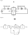
- FIG. 3 illustrates an example electroacoustic model 70 for a loudspeaker device 60 ( FIG. 2 ) driven by a voltage source amplifier 71.
- One or more loudspeaker parameters i.e., loudspeaker characteristics
- loudspeaker characteristics for the loudspeaker device 60 may be classified into one of the following domains: an electrical domain or a mechanical domain.
- examples of different loudspeaker parameters include, but are not limited to, the following: (1) an applied voltage u* from the voltage source amplifier 71 for driving a speaker driver 65 of the loudspeaker device 60, (2) an electrical resistance Re of a driver voice coil 57 of the speaker driver 65, (3) a current i* flowing through the driver voice coil 57 as a result of the applied voltage u*, (4) an inductance L_e of the driver voice coil 57, and (5) a back electromagnetic force (back EMF) Bl • ⁇ resulting from the motion of the driver voice coil 57 in the magnetic field of the motor structure (i.e., driver voice coil 57, top plate 61, magnet 62, bottom plate 63, and pole piece 66) of the speaker driver 65, wherein the back-EMF Bl • ⁇ represents a product of a force factor Bl of the motor structure and a velocity ⁇ of one or more moving components of the speaker driver 65 (e.g., a diaphragm 56, the driver voice
- examples of different loudspeaker parameters include, but are not limited to, the following: (1) the velocity x of the one or more moving components of the speaker driver 65, (2) a mechanical mass M ms of the one or more moving components (i.e., moving mass) and air load, (3) a mechanical resistance R ms representing the mechanical losses of the speaker driver 65, (4) a stiffness factor K ms of the suspension (i.e., surround roll 58, spider 67, plus air load) of the speaker driver 65, and (5) a mechanical force Bl • i* applied on the one or more moving components, wherein the mechanical force Bl * i* represents a product of the force factor Bl of the motor structure and the current i* flowing through the driver voice coil 57.
- the state of a loudspeaker device 60 at each instant may be described using each of the following: (1) a displacement x of the one or more moving components of the speaker driver 65, (2) a velocity ⁇ of the one or more moving components of the speaker driver 65, and (3) a current i flowing through the driver voice coil 57.
- X1(t) generally denote a vector representing a state ("state vector representation") of the loudspeaker device 60 at a sampling time t.
- the system 200 determines, at each sampling time t, an estimated displacement x of the one or more moving components at the sampling time t, an estimated velocity ⁇ of the one or more moving components at the sampling time t, and an estimated current i flowing through the driver voice coil 57 at a sampling time t based on a physical model of the loudspeaker device 60, such as a linear model (e.g., a linear state-space model as shown in FIG. 4A ) or a nonlinear model (e.g., a nonlinear state-space model as shown in FIG. 4B ).
- the physical model may be based on one or more loudspeaker parameters for the loudspeaker device 60.
- FIG. 4A illustrates an example linear system 500 representing a linear state-space model of the loudspeaker device 60.
- the linear system 500 may be utilized to determine an estimated displacement x of one or more moving components (e.g., a diaphragm 56 and/or a driver voice coil 57) of the speaker driver 65 based on a state vector representation X1 of the loudspeaker device 60 and an input voltage u of a source signal for reproduction via the loudspeaker device 60.
- moving components e.g., a diaphragm 56 and/or a driver voice coil 57
- ⁇ 1 generally denote a time derivative (i.e., rate of change) of the state vector representation X1 of the loudspeaker device 60 ("state vector rate of change").
- A1, B1, and C1 denote constant parameter matrices.
- the constant parameter matrices A1, B1, and C1 may be represented in accordance with equations (3)-(5) provided below:
- Determining an estimated displacement x of the one or more moving components utilizing the linear system 500 involves performing a set of computations that are based on equations (2)-(6) provided above.
- the linear system 500 may utilize one or more of the following components to perform the set of computations: (1) a first multiplication unit 501 configured to determine a product term A1X1 by multiplying the constant parameter matrix A1 with the state vector representation X1, (2) a second multiplication unit 502 configured to determine a product term B1u by multiplying the constant parameter matrix B 1 with the input voltage u, (3) an addition unit 503 configured to determine the state vector rate of change ⁇ 1 by adding the product terms A1X1 and Bu in accordance with equation (2) provided above, (4) an integration unit 504 configured to determine the state vector representation X1 by integrating the state vector rate of change ⁇ 1 in the time domain, and (5) a third multiplication unit 505 configured to determine the estimated displacement x by multiplying the constant parameter matrix C1 with the state vector representation X1 in accordance with equation (6) provided above
- the system representation 500 in FIG. 4A is a linear system that receives an input voltage u as an input and provides an estimated displacement x as an output.
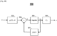
- FIG. 4B illustrates an example nonlinear system 550 representing a nonlinear state-space physical model of the loudspeaker device 60.
- the nonlinear system 550 may be utilized to determine an estimated displacement x of one or more moving components (e.g., a diaphragm 56 and/or a driver voice coil 57) of the speaker driver 65 based on a state vector representation X1 of the loudspeaker device 60 and an input voltage u of a source signal for reproduction via the loudspeaker device 60.
- moving components e.g., a diaphragm 56 and/or a driver voice coil 57
- g1(X1, u) and f1(X1) generally denote nonlinear functions that are based on the state vector representation X1 of the loudspeaker device 60 and one or more large signal loudspeaker parameters for the loudspeaker device 60.
- C1 generally denote a constant parameter matrix.
- ⁇ 1 generally denote a time derivative (i.e., rate of change) of the state vector representation X1 of the loudspeaker device 60 ("state vector rate of change").
- Determining an estimated displacement x of the one or more moving components utilizing the nonlinear system 550 involves performing a set of computations that are based on equations (7)-(11) provided above.
- the nonlinear system 550 may utilize one or more of the following components to perform the set of computations: (1) a first computation unit 551 configured to compute the nonlinear function f1(X1) in accordance with equation (8) provided above, (2) a second computation unit 552 configured to compute the nonlinear function g1(X1, u) in accordance with equation (7) provided above, (3) an addition unit 553 configured to determine the state vector rate of change ⁇ 1 by adding the nonlinear functions g1(X1, u) and f1(X1) in accordance with equation (10) provided above, (4) an integration unit 554 configured to determine the state vector representation X1 by integrating the state vector rate of change ⁇ 1 in the time-domain, and (5) a multiplication unit 555 configured to determine the estimated displacement x by multiplying the constant parameter matrix C1
- the system representation 550 in FIG. 4B is a nonlinear system that receives an input voltage u as an input and provides an estimated displacement x as an output.
- total energy stored in the loudspeaker device 60 may be represented as a sum of potential energy, kinetic energy, and electrical energy in the loudspeaker device 60, as expressed by equation (12) provided below:
- E 1 2 K ms x 2 + 1 2 M ms x ⁇ 2 + 1 2 L e i 2
- 1/2 K ms x 2 denotes the potential energy in the loudspeaker device 60
- 1/2 M ms ⁇ 2 denotes the kinetic energy in the loudspeaker device 60
- 1/2 L e i 2 denotes the electrical energy in the loudspeaker device 60.
- x sup generally denote a maximum potential displacement (e.g., predicted maximum cone displacement) of the one or more moving components of the speaker driver 65, wherein the maximum potential displacement x sup can be either a positive value (+x sup ) or a negative value (-x sup ).
- x lim generally denote a predetermined displacement limit (i.e., maximum desired displacement) for safe displacement of the one or more moving components of the speaker driver 65
- [-x lim , x lim ] generally denote a predetermined range of safe displacement of the one or more moving components of the speaker driver 65.
- the system 200 ensures that the maximum potential displacement x sup does not exceed the predetermined displacement limit x lim .
- total energy E stored in the loudspeaker device 60 must be limited to satisfy a constraint represented by expression (15) provided below: E ⁇ 1 2 K ms x lim 2
- dE/dt generally denote total power in the loudspeaker device 60, wherein the total power dE/dt is a time derivative (i.e., rate of change) of total energy E stored in the loudspeaker device 60.
- the total power dE/dt in the loudspeaker device 60 is negative due to mechanical and electrical losses, and the total energy E stored in the loudspeaker device 60 decreases to zero (i.e., stability).
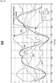
- FIG. 5 is an example graph 300 illustrating different loudspeaker parameters for a loudspeaker device 60 during audio reproduction.
- a horizontal axis of the graph 300 represents time in seconds (s).
- the graph 300 comprises each of the following: (1) a first curve 301 representing a current i flowing through a driver voice coil 57 of a speaker driver 65 of the loudspeaker device 60 in Amperes (A), (2) a second curve 302 representing velocity x of one or more moving components (e.g., a diaphragm 56 and/or the driver voice coil 57) of the speaker driver 65 in meters per second (m/s), (3) a third curve 303 representing a negative value of maximum potential displacement -x sup of the one or more moving components of the speaker driver 65 in millimeters (mm), (4) a fourth curve 304 representing a positive value of maximum potential displacement x sup of the one or more moving components of the speaker driver 65 in mm, and (5) a fifth curve 305 representing displacement x of the one or
- the displacement x of the one or moving components of the speaker driver 65 reaches ⁇ x sup ("maximum displacement envelope") when the velocity ⁇ of the one or more moving components of the speaker driver 65 crosses zero.
- ⁇ x sup maximum displacement envelope
- FIG. 6 illustrates an example energy limiter system 200, in accordance to an embodiment.
- the system 200 provides a limiter and/or a compressor for limiting and/or compressing total energy stored in a loudspeaker device 60, which in turn limits and/or compresses displacement x of one or more moving components of a speaker driver 65 (e.g., a diaphragm 56, the driver voice coil 57, and/or the former 64) of the loudspeaker device 60.
- a speaker driver 65 e.g., a diaphragm 56, the driver voice coil 57, and/or the former 64
- the system 200 comprises a loudspeaker model unit 310 configured to receive, as inputs, an input voltage u at a sampling time t and one or more loudspeaker parameters for the loudspeaker device 60 (e.g., small-signal loudspeaker parameters for the loudspeaker device 60, such as mechanical mass M ms , inductance L e , and stiffness factor K ms ). Based on the inputs received and a physical model of the loudspeaker device 60 (e.g., a linear state-space model as shown in FIG. 4A or a nonlinear state-space model as shown in FIG.
- a physical model of the loudspeaker device 60 e.g., a linear state-space model as shown in FIG. 4A or a nonlinear state-space model as shown in FIG.
- the loudspeaker model unit 310 is configured to recursively determine each of the following: an estimated displacement x of the one or more moving components of the speaker driver 65 at the sampling time t, an estimated velocity ⁇ of the one or more moving components of the speaker driver 65 at the sampling time t, and an estimated current i flowing through a driver voice coil 57 of the speaker driver 65 at the sampling time t.
- the system 200 comprises an energy computation unit 320 configured to receive, as inputs, an estimated displacement x of the one or more moving components of the speaker driver 65 at a sampling time t (e.g., from the loudspeaker model unit 310), an estimated velocity ⁇ of the one or more moving components of the speaker driver 65 at the sampling time t (e.g., from the loudspeaker model unit 310), an estimated current i flowing through the driver voice coil 57 at the sampling time t (e.g., from the loudspeaker model unit 310), and one or more loudspeaker parameters for the loudspeaker device 60 (e.g., small-signal loudspeaker parameters for the loudspeaker device 60, such as mechanical mass M ms , inductance L e , and stiffness factor K ms ). Based on the inputs received, the energy computation unit 320 is configured to determine total energy E stored in the loudspeaker device 60 at the sampling time t.
- a sampling time t e.g.,
- the energy computation unit 320 is configured to determine total energy E stored in the loudspeaker device 60 by: (1) computing, based on the inputs received, potential energy in the loudspeaker device 60, kinetic energy in the loudspeaker device 60, and electrical energy in the loudspeaker device 60, and (2) computing a sum of the potential energy, the kinetic energy, and the electrical energy, wherein the total energy E stored in the loudspeaker device 60 factors into account the sum computed.
- the energy computation unit 320 is configured to determine total energy E stored in the loudspeaker device 60 based on a predictive model trained to learn dynamics of energy.
- the system 200 comprises a static gain computation unit 330 configured to receive, as inputs, an estimated total energy E stored in the loudspeaker device 60 at a sampling time t (e.g., from the energy computation unit 320) and a set of displacement parameters indicative of a desired displacement behavior of the one or more moving components of the speaker driver 65.
- the set of displacement parameters comprise, but is not limited to, one or more of the following displacement parameters: a predetermined displacement limit x lim , a predetermined displacement compression threshold x thr , a predetermined compression ratio R, or a predetermined soft knee width W knee .
- the static gain computation unit 330 is configured to determine an instantaneous gain G static to apply at the sampling time t to limit and/or compress the displacement x of the one or more moving components of the speaker driver 65 at the sampling time t.
- the system 200 operates as a limiter (i.e., the limiter is enabled) to limit total energy E stored in the loudspeaker 60 based on a predetermined energy limit E lim .
- the system 200 operates as a compressor (i.e., the compressor is enabled) to compress total energy E stored in the loudspeaker 60 based on a predetermined energy compression threshold E thr .
- the system 200 is operable as one of the following: a limiter only, a compressor only, or both a limiter and a compressor.
- the static gain computation unit 330 is configured to convert one or more displacement parameters to one or more corresponding energy parameters, such as a predetermined energy limit E lim and/or a predetermined energy compression threshold E thr .
- the static gain computation unit 330 determines an instantaneous gain G static to apply at a sampling time t to limit and compress a displacement x of the one or more moving components of the speaker driver 65 at the sampling time t in accordance with equations (22)-(25) provided below:
- G static 0 if E ⁇ E thr ⁇ W knee 2
- G static E ⁇ E thr + W knee 2 2 1 R ⁇ 1 2 W knee if E thr ⁇ W knee 2 ⁇ E ⁇ E thr + W knee 2
- G static E ⁇ E thr 1 R ⁇ 1 if E thr + W knee 2 ⁇ E ⁇ E lim and
- G static E lim ⁇ E if E lim ⁇ E
- the system 200 comprises a temporal gain smoothing unit 340 configured to implement temporal gain smoothing (i.e., gain attenuation).
- the temporal gain smoothing unit 340 is configured to: (1) receive, as inputs, an instantaneous gain G static at a sampling time t (e.g., from the static gain computation unit 330), an optional set of attack parameters for reducing the gain G static (i.e., attack), and an optional set of release parameters for increasing the gain G static (i.e., release), and (2) apply a smoothing algorithm to the gain G static to reduce or prevent rapid changes in the gain G static that can adversely affect perceived sound quality, resulting in a smoothed gain G smoothed .
- the temporal gain smoothing unit 340 is configured to apply any type of smoothing algorithm.
- the smoothing algorithm applied involves adjusting the gain G static exponentially utilizing the set of attack parameters and/or the set of release parameters.
- the system 200 comprises an optional look-ahead delay unit 350 configured to: (1) receive an input voltage u at a sampling time t, and (2) implement a look-ahead delay by delaying the input voltage u for a predetermined amount of time (e.g., 20 ms) to allow for temporal gain smoothing (e.g., implemented by the temporal gain smoothing unit 340). Delaying the input voltage u allows for gain attenuation before total energy E stored in the loudspeaker device 60 exceeds a predetermined energy compression threshold E thr . In one embodiment, the system 200 minimizes or eliminates the look-ahead delay by estimating/predicting a state of the loudspeaker device 60, thereby removing the need for the look-ahead delay unit 350.
- a predetermined amount of time e.g. 20 ms
- temporal gain smoothing e.g., implemented by the temporal gain smoothing unit 340. Delaying the input voltage u allows for gain attenuation before total energy E stored in the loudspeak
- the system 200 comprises a component 360 configured to receive, as inputs, a smoothed gain G smoothed to apply at a sampling time t (e.g., from the temporal gain smoothing unit 340), and an input voltage u at the sampling time t (e.g., from the look-ahead delay unit 350 if look-ahead delay is implemented).
- a smoothed gain G smoothed to apply at a sampling time t e.g., from the temporal gain smoothing unit 340
- an input voltage u at the sampling time t e.g., from the look-ahead delay unit 350 if look-ahead delay is implemented.
- the component 360 is configured to attenuate the input voltage u by applying the smoothed gain G_smoothed to the input voltage u, resulting in a limiting voltage u lim at the sampling time t that limits and/or compresses total energy E stored in the loudspeaker device 60 at the sampling time t and in turn limits and/or compresses an actual displacement (e.g., actual cone displacement) of the one or more moving components of the speaker driver 65 to within a predetermined range of safe displacement [-x lim , x lim ] at the sampling time t.
- an actual displacement e.g., actual cone displacement
- FIG. 7A is an example graph 400 comparing differences in voltage as result of enabling the limiter, in accordance with an embodiment.
- a horizontal axis of the graph 400 represents time in s.
- a vertical axis of the graph 400 represents voltage in V.
- the graph 400 comprises a first curve 401 representing an actual voltage driving the speaker driver 65 when the limiter is not enabled (i.e., actual voltage u* is substantially about input voltage u), and a second curve 402 representing an actual voltage driving the speaker driver 65 when the limiter is enabled (i.e., actual voltage u* is substantially about limiting voltage u lim ).
- FIG. 7B is an example graph 410 illustrating total energy as result of enabling the limiter, in accordance with an embodiment.
- a horizontal axis of the graph 410 represents time in s.
- a vertical axis of the graph 410 represents energy in Joules (J).
- the graph 410 comprises a first curve 411 representing total energy stored in the loudspeaker device 60 when the limiter is not enabled, and a second curve 412 representing total energy stored in the loudspeaker device 60 when the limiter is enabled. If the limiter is enabled, the system 200 adjusts the limiting voltage u lim to keep the total energy E stored in the loudspeaker device 60 below a predetermined energy limit E lim , as shown in FIG. 7B .
- FIG. 7C is an example graph 420 comparing differences in displacement as result of enabling the limiter, in accordance with an embodiment.
- a horizontal axis of the graph 420 represents time in s.
- a vertical axis of the graph 420 represents displacement in mm.
- the graph 420 comprises a first curve 421 representing an actual displacement of the one or more moving components of the speaker driver 65 when the limiter is not enabled, and a second curve 422 representing an actual displacement of the one or more moving components of the speaker driver 65 when the limiter is enabled. If the limiter is enabled, the system 200 applies a gain that limits actual displacement of the one or more moving components of the speaker driver 65 to within a predetermined range of safe displacement [-x lim , x lim ].
- the system 200 with the limiter enabled applies a gain that limits the actual displacement x* of the one or more moving components of the speaker driver 65 to within a range [-5, 5], as shown in FIG. 7C .
- FIG. 7D is an example graph 430 comparing gain G static with smoothed gain G_smoothed, in accordance with an embodiment.
- a horizontal axis of the graph 430 represents time in s.
- a vertical axis of the graph 430 represents gain in dB.
- the graph 430 comprises a first curve 431 representing static gain G static , and a second curve 432 representing smoothed gain G smoothed .
- the smoothing algorithm applied by the system 200 involves adjusting an instantaneous gain G static exponentially utilizing a set of attack parameters and/or a set of release parameters. As shown in FIG.
- G smoothed G high ⁇ G low e ⁇ t / ⁇ attack + G low wherein ⁇ attack is a time constant representing an amount of time it takes for the gain G static to get within 36.8% of the smoothed gain G smoothed .
- G smoothed G high ⁇ G low 1 ⁇ e ⁇ t / ⁇ release + G low wherein ⁇ release is a time constant representing an amount of time it takes for the gain G static to get within 36.8% of the smoothed gain G_smoothed.
- ⁇ attack is 2 ms
- ⁇ release is 50ms
- the look-ahead delay is 3 ms.
- ⁇ attack , ⁇ release , and the look-ahead delay have different values for different implementations.
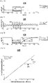
- FIG. 8 is an example graph 440 comparing displacement when only the limiter is enabled with displacement when the limiter is not enabled, in accordance with an embodiment.
- a horizontal axis of the graph 440 represents an estimated displacement of one or more moving components of a speaker driver 65 of a loudspeaker device 60 in dB mm.
- a vertical axis of the graph 440 represents an actual displacement of the one or more moving components of the speaker driver 65 in dB mm.
- the graph 440 comprises a first curve 441 representing the actual displacement of the one or more moving components of the speaker driver 65 when the limiter is not enabled, and a second curve 442 representing the actual displacement of the one or more moving components of the speaker driver 65 when only the limiter is enabled.
- a predetermined displacement limit x lim is 16.9 dB mm (i.e., 7.0 mm)
- the system 200 with the limiter enabled applies an instantaneous gain that limits actual displacement of the one or more moving components of the speaker driver 65 to substantially about 16.9 dB mm, as shown in FIG. 8 .
- FIG. 9 is an example graph 450 comparing displacement when both the limiter and the compressor are enabled with displacement when neither the limiter nor the compressor are enabled, in accordance with an embodiment.
- a horizontal axis of the graph 450 represents an estimated displacement of one or more moving components of a speaker driver 65 of a loudspeaker device 60 in dB mm.
- a vertical axis of the graph 450 represents an actual displacement of the one or more moving components of the speaker driver 65 in dB mm.
- the graph 450 comprises a first curve 451 representing the actual displacement of the one or more moving components of the speaker driver 65 when neither the limiter nor the compressor are enabled, and a second curve 452 representing the actual displacement of the one or more moving components of the speaker driver 65 when both the limiter and the compressor are enabled.
- a predetermined displacement limit x lim is 16.9 dB mm (i.e., 7.0 mm)
- a predetermined displacement compression threshold x thr is 12.0 dB mm (i.e., 4.0 mm)
- a predetermined compression ratio R is 2: 1
- a predetermined soft knee width W_knee is 6 dB
- FIG. 10 is an example flowchart of a process 700 for limiting energy in a loudspeaker, in accordance with an embodiment.
- Process block 701 includes determining a state of a loudspeaker (e.g., loudspeaker device 60) based on a physical model of the loudspeaker (e.g., a linear state-space model as shown in FIG. 4A or a nonlinear state-space model as shown in FIG. 4B ) and a source signal for reproduction via the loudspeaker.
- Process block 702 includes determining a potential energy in the loudspeaker, a kinetic energy in the loudspeaker, and an electrical energy in the loudspeaker based on the state of the loudspeaker.
- Process block 703 includes determining a total energy stored in the loudspeaker based on the potential energy, the kinetic energy, and the electrical energy.
- Process block 704 includes determining a maximum potential displacement of a diaphragm of a speaker driver of the loudspeaker based on the total energy.
- Process block 705 includes limiting the total energy stored in the loudspeaker by attenuating the source signal, wherein an actual displacement of the diaphragm during the reproduction of the source signal is controlled based on the attenuated source signal.
- one or more components of the energy limiter system 200 are configured to perform process blocks 701-705.
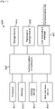
- FIG. 11 is a high-level block diagram showing an information processing system comprising a computer system 600 useful for implementing various disclosed embodiments.
- the computer system 600 includes one or more processors 601, and can further include an electronic display device 602 (for displaying video, graphics, text, and other data), a main memory 603 (e.g., random access memory (RAM)), storage device 604 (e.g., hard disk drive), removable storage device 605 (e.g., removable storage drive, removable memory module, a magnetic tape drive, optical disk drive, computer readable medium having stored therein computer software and/or data), user interface device 606 (e.g., keyboard, touch screen, keypad, pointing device), and a communication interface 607 (e.g., modem, a network interface (such as an Ethernet card), a communications port, or a PCMCIA slot and card).
- a network interface such as an Ethernet card
- communications port such as an Ethernet card
- PCMCIA slot and card PCMCIA slot and card
- the communication interface 607 allows software and data to be transferred between the computer system 600 and external devices.
- the nonlinear controller 600 further includes a communications infrastructure 608 (e.g., a communications bus, cross-over bar, or network) to which the aforementioned devices/modules 601 through 607 are connected.
- a communications infrastructure 608 e.g., a communications bus, cross-over bar, or network
- Information transferred via the communications interface 607 may be in the form of signals such as electronic, electromagnetic, optical, or other signals capable of being received by communications interface 607, via a communication link that carries signals and may be implemented using wire or cable, fiber optics, a phone line, a cellular phone link, a radio frequency (RF) link, and/or other communication channels.
- Computer program instructions representing the block diagrams and/or flowcharts herein may be loaded onto a computer, programmable data processing apparatus, or processing devices to cause a series of operations performed thereon to produce a computer implemented process.
- processing instructions for process 700 ( FIG. 10 ) may be stored as program instructions on the memory 603, storage device 604, and/or the removable storage device 605 for execution by the processor 601.
- Embodiments have been described with reference to flowchart illustrations and/or block diagrams of methods, apparatus (systems), and computer program products.
- each block of such illustrations/diagrams, or combinations thereof can be implemented by computer program instructions.
- the computer program instructions when provided to a processor produce a machine, such that the instructions, which executed via the processor create means for implementing the functions/operations specified in the flowchart and/or block diagram.
- Each block in the flowchart /block diagrams may represent a hardware and/or software module or logic.
- the functions noted in the blocks may occur out of the order noted in the figures, concurrently, etc.
- computer program medium “computer usable medium,” “computer readable medium,” and “computer program product,” are used to generally refer to media such as main memory, secondary memory, removable storage drive, a hard disk installed in hard disk drive, and signals. These computer program products are means for providing software to the computer system.
- the computer readable medium allows the computer system to read data, instructions, messages or message packets, and other computer readable information from the computer readable medium.
- the computer readable medium may include non-volatile memory, such as a floppy disk, ROM, flash memory, disk drive memory, a CD-ROM, and other permanent storage. It is useful, for example, for transporting information, such as data and computer instructions, between computer systems.
- Computer program instructions may be stored in a computer readable medium that can direct a computer, other programmable data processing apparatuses, or other devices to function in a particular manner, such that the instructions stored in the computer readable medium produce an article of manufacture including instructions which implement the function/act specified in the flowchart and/or block diagram block(s).
- aspects of the embodiments may be embodied as a system, method or computer program product. Accordingly, aspects of the embodiments may take the form of an entirely hardware embodiment, an entirely software embodiment (including firmware, resident software, micro-code, etc.) or an embodiment combining software and hardware aspects that may all generally be referred to herein as a "circuit,” “module,” or “system.” Furthermore, aspects of the embodiments may take the form of a computer program product embodied in one or more computer readable medium(s) having computer readable program code embodied thereon.
- the computer readable medium may be a computer readable storage medium (e.g., a non-transitory computer readable storage medium).
- a computer readable storage medium may be, for example, but not limited to, an electronic, magnetic, optical, electromagnetic, infrared, or semiconductor system, apparatus, or device, or any suitable combination of the foregoing.
- a computer readable storage medium may be any tangible medium that can contain, or store a program for use by or in connection with an instruction execution system, apparatus, or device.
- Computer program code for carrying out operations for aspects of one or more embodiments may be written in any combination of one or more programming languages, including an object oriented programming language such as Java, Smalltalk, C++, or the like, and conventional procedural programming languages, such as the "C" programming language or similar programming languages.
- the program code may execute entirely on the user's computer, partly on the user's computer, as a stand-alone software package, partly on the user's computer and partly on a remote computer or entirely on the remote computer or server.
- the remote computer may be connected to the user's computer through any type of network, including a local area network (LAN) or a wide area network (WAN), or the connection may be made to an external computer (for example, through the Internet using an Internet Service Provider).
- LAN local area network
- WAN wide area network
- Internet Service Provider for example, AT&T, MCI, Sprint, EarthLink, MSN, GTE, etc.
- These computer program instructions may also be stored in a computer readable medium that can direct a computer, other programmable data processing apparatus, or other devices to function in a particular manner, such that the instructions stored in the computer readable medium produce an article of manufacture including instructions which implement the function/act specified in the flowchart and/or block diagram block(s).
- the computer program instructions may also be loaded onto a computer, other programmable data processing apparatuses, or other devices to cause a series of operational steps to be performed on the computer, other programmable apparatuses, or other devices to produce a computer implemented process such that the instructions which execute on the computer or other programmable apparatuses provide processes for implementing the functions/acts specified in the flowchart and/or block diagram block(s).
- each block in the flowchart or block diagrams may represent a module, segment, or portion of instructions, which comprises one or more executable instructions for implementing the specified logical function(s).
- the functions noted in the block may occur out of the order noted in the figures.
- two blocks shown in succession may, in fact, be executed substantially concurrently, or the blocks may sometimes be executed in the reverse order, depending upon the functionality involved.
Landscapes
- Engineering & Computer Science (AREA)
- Physics & Mathematics (AREA)
- Acoustics & Sound (AREA)
- Signal Processing (AREA)
- Health & Medical Sciences (AREA)
- General Health & Medical Sciences (AREA)
- Otolaryngology (AREA)
- Multimedia (AREA)
- Circuit For Audible Band Transducer (AREA)
Claims (15)
- Verfahren, das Folgendes umfasst:Bestimmen einer potentiellen Energie in einem Lautsprecher, einer kinetischen Energie in dem Lautsprecher und einer elektrischen Energie in dem Lautsprecher auf der Grundlage eines physikalischen Modells des Lautsprechers;Bestimmen der im Lautsprecher gespeicherten Gesamtenergie auf der Grundlage der potentiellen Energie, der kinetischen Energie und der elektrischen Energie;Bestimmen einer maximal möglichen Auslenkung einer Membran eines Lautsprechertreibers des Lautsprechers auf der Grundlage der Gesamtenergie; undBegrenzung der im Lautsprecher gespeicherten Gesamtenergie durch Dämpfung eines Quellensignals für die Wiedergabe über den Lautsprecher, wobei eine tatsächliche Auslenkung der Membran während der Wiedergabe des Quellensignals auf der Grundlage des gedämpften Quellensignals gesteuert wird, wodurch die tatsächliche Auslenkung der Membran innerhalb eines vorbestimmten Bereichs sicherer Auslenkung begrenzt wird, der den bestimmten Bereich maximaler möglicher Auslenkung einschließt.
- Verfahren nach Anspruch 1, ferner umfassend:
rekursives Bestimmen einer geschätzten Verschiebung der Membran, einer geschätzten Geschwindigkeit der Membran oder eines geschätzten Stroms, der durch eine Treiberschwingspule des Lautsprechertreibers fließt, basierend auf dem physikalischen Modell des Lautsprechers und einer Spannung des Quellensignals. - Verfahren nach Anspruch 1, wobei das Dämpfen des Quellensignals umfasst:Bestimmen einer momentanen Verstärkung auf der Grundlage der Gesamtenergie und einer Reihe von Parametern;Abschwächen der Verstärkung durch Anwendung eines Glättungsalgorithmus auf die Verstärkung; undAnwendung der abgeschwächten Verstärkung auf eine Spannung des Quellsignals.
- Verfahren nach Anspruch 3, wobei der Glättungsalgorithmus die exponentielle Anpassung der Verstärkung unter Verwendung eines Attack-Parameters und/oder eines Release-Parameters beinhaltet.
- Verfahren nach Anspruch 1, wobei die tatsächliche Auslenkung der Membran während der Wiedergabe des Quellensignals auf der Grundlage des gedämpften Quellensignals begrenzt wird.
- Verfahren nach Anspruch 1, wobei die tatsächliche Auslenkung der Membran während der Wiedergabe des Quellensignals auf der Grundlage des gedämpften Quellensignals komprimiert wird.
- Verfahren nach Anspruch 1, ferner umfassend:
Bestimmen eines Zustands des Lautsprechers auf der Grundlage des physikalischen Modells des Lautsprechers und des Quellensignals, wobei die potentielle Energie, die kinetische Energie und die elektrische Energie in dem Lautsprecher auf der Grundlage des Zustands des Lautsprechers bestimmt werden. - System zur Begrenzung der Energie in einem Lautsprecher, wobei das System Folgendes umfasst:einen Spannungsquellenverstärker (71), der so konfiguriert ist, dass er mit dem Lautsprecher verbunden werden kann; undeinen Begrenzer (200), der mit dem Spannungsquellenverstärker verbunden ist, wobei der Begrenzer konfiguriert ist zum:Bestimmen einer potentiellen Energie im Lautsprecher, einer kinetischen Energie im Lautsprecher und einer elektrischen Energie im Lautsprecher auf der Grundlage eines physikalischen Modells des Lautsprechers;Bestimmen der im Lautsprecher gespeicherten Gesamtenergie auf der Grundlage der potentiellen Energie, der kinetischen Energie und der elektrischen Energie;Bestimmen einer maximalen potentiellen Auslenkung einer Membran eines Lautsprechertreibers des Lautsprechers basierend auf der Gesamtenergie; undBegrenzung der im Lautsprecher gespeicherten Gesamtenergie durch Dämpfung einer Spannung eines Quellensignals zur Wiedergabe über den Lautsprecher, wobei der Spannungsquellenverstärker die gedämpfte Spannung ausgibt, um den Lautsprechertreiber anzusteuern, und eine tatsächliche Auslenkung der Membran während der Wiedergabe des Quellensignals auf der Grundlage der gedämpften Spannung gesteuert wird, wodurch verhindert wird, dass die tatsächliche Auslenkung der Membran innerhalb eines vorbestimmten Bereichs sicherer Auslenkung liegt, der den bestimmten Bereich maximaler potenzieller Auslenkung umfasst.
- System nach Anspruch 8, wobei der Begrenzer ferner konfiguriert ist zum:
Rekursiven Bestimmen mindestens einer geschätzten Verschiebung der Membran, einer geschätzten Geschwindigkeit der Membran oder eines geschätzten Stroms, der durch eine Treiberschwingspule des Lautsprechertreibers fließt, auf der Grundlage des physikalischen Modells des Lautsprechers und der Spannung. - System nach Anspruch 8, wobei die Dämpfung der Spannung umfasst:Bestimmen einer momentanen Verstärkung auf der Grundlage der Gesamtenergie und einer Reihe von Parametern;Abschwächen der Verstärkung durch Anwendung eines Glättungsalgorithmus auf die Verstärkung; undAnwendung der abgeschwächten Verstärkung auf die Spannung.
- System nach Anspruch 10, wobei der Glättungsalgorithmus die exponentielle Anpassung der Verstärkung unter Verwendung eines Attack-Parameters und/oder eines Release-Parameters beinhaltet.
- System nach Anspruch 10, wobei die tatsächliche Auslenkung der Membran während der Wiedergabe des Quellensignals auf der Grundlage der gedämpften Spannung entweder begrenzt oder komprimiert wird.
- Lautsprechervorrichtung (60), die Folgendes umfasst:einen Lautsprechertreiber (65) mit einer Membran;einen Spannungsquellenverstärker (71), der mit dem Lautsprechertreiber verbunden ist; undeinen Begrenzer (200), der mit dem Spannungsquellenverstärker verbunden ist, wobei der Begrenzer konfiguriert ist, um:Bestimmen einer potentiellen Energie in der Lautsprechereinrichtung, einer kinetischen Energie in der Lautsprechereinrichtung und einer elektrischen Energie in der Lautsprechereinrichtung auf der Grundlage eines physikalischen Modells der Lautsprechereinrichtung;Bestimmen der in der Lautsprechervorrichtung gespeicherten Gesamtenergie auf der Grundlage der potentiellen Energie, der kinetischen Energie und der elektrischen Energie;Bestimmen einer maximalen potentiellen Auslenkung einer Membran eines Lautsprechertreibers der Lautsprechervorrichtung basierend auf der Gesamtenergie; und Begrenzung der in der Lautsprechervorrichtung gespeicherten Gesamtenergie durch Dämpfung einer Spannung eines Quellensignals für die Wiedergabe über die Lautsprechervorrichtung, wobei der Spannungsquellenverstärker die gedämpfte Spannung ausgibt, um den Lautsprechertreiber anzusteuern, und eine tatsächliche Auslenkung der Membran während der Wiedergabe des Quellensignals auf der Grundlage der gedämpften Spannung gesteuert wird, wodurch die tatsächliche Auslenkung der Membran innerhalb eines vorbestimmten Bereichs der sicheren Auslenkung begrenzt, der den bestimmten Bereich der maximalen potenziellen Auslenkung umfasst.
- Lautsprechervorrichtung nach Anspruch 13, wobei der Begrenzer ferner konfiguriert zum:
rekursiven Bestimmen mindestens einer geschätzten Verschiebung der Membran, einer geschätzten Geschwindigkeit der Membran oder eines geschätzten Stroms, der durch eine Treiberschwingspule des Lautsprechertreibers fließt, auf der Grundlage des physikalischen Modells des Lautsprechers und der Spannung. - Lautsprechervorrichtung nach Anspruch 13, wobei die Dämpfung der Spannung umfasst:Bestimmung einer momentanen Verstärkung auf der Grundlage der Gesamtenergie und einer Reihe von Parametern;Abschwächen der Verstärkung durch Anwendung eines Glättungsalgorithmus auf die Verstärkung; undAnwendung der abgeschwächten Verstärkung auf die Spannung.
Applications Claiming Priority (3)
| Application Number | Priority Date | Filing Date | Title |
|---|---|---|---|
| US201862640448P | 2018-03-08 | 2018-03-08 | |
| US16/224,604 US10701485B2 (en) | 2018-03-08 | 2018-12-18 | Energy limiter for loudspeaker protection |
| PCT/KR2019/002741 WO2019172715A1 (en) | 2018-03-08 | 2019-03-08 | Energy limiter for loudspeaker protection |
Publications (3)
| Publication Number | Publication Date |
|---|---|
| EP3744111A1 EP3744111A1 (de) | 2020-12-02 |
| EP3744111A4 EP3744111A4 (de) | 2021-02-24 |
| EP3744111B1 true EP3744111B1 (de) | 2023-01-25 |
Family
ID=67843710
Family Applications (1)
| Application Number | Title | Priority Date | Filing Date |
|---|---|---|---|
| EP19763318.3A Active EP3744111B1 (de) | 2018-03-08 | 2019-03-08 | Energiebegrenzer für lautsprecherschutz |
Country Status (5)
| Country | Link |
|---|---|
| US (1) | US10701485B2 (de) |
| EP (1) | EP3744111B1 (de) |
| KR (1) | KR102654121B1 (de) |
| CN (1) | CN111869232B (de) |
| WO (1) | WO2019172715A1 (de) |
Families Citing this family (14)
| Publication number | Priority date | Publication date | Assignee | Title |
|---|---|---|---|---|
| US10547942B2 (en) | 2015-12-28 | 2020-01-28 | Samsung Electronics Co., Ltd. | Control of electrodynamic speaker driver using a low-order non-linear model |
| US10462565B2 (en) | 2017-01-04 | 2019-10-29 | Samsung Electronics Co., Ltd. | Displacement limiter for loudspeaker mechanical protection |
| US10506347B2 (en) | 2018-01-17 | 2019-12-10 | Samsung Electronics Co., Ltd. | Nonlinear control of vented box or passive radiator loudspeaker systems |
| US10542361B1 (en) | 2018-08-07 | 2020-01-21 | Samsung Electronics Co., Ltd. | Nonlinear control of loudspeaker systems with current source amplifier |
| US11012773B2 (en) | 2018-09-04 | 2021-05-18 | Samsung Electronics Co., Ltd. | Waveguide for smooth off-axis frequency response |
| US10797666B2 (en) | 2018-09-06 | 2020-10-06 | Samsung Electronics Co., Ltd. | Port velocity limiter for vented box loudspeakers |
| US10897670B1 (en) * | 2018-10-31 | 2021-01-19 | Amazon Technologies, Inc. | Excursion and thermal management for audio output devices |
| WO2021177883A1 (en) * | 2020-03-04 | 2021-09-10 | Dirac Research Ab | Audio signal processing for adaptively adjusting a gain |
| US12160214B2 (en) | 2020-03-13 | 2024-12-03 | Immersion Networks, Inc. | Loudness equalization system |
| US11356773B2 (en) | 2020-10-30 | 2022-06-07 | Samsung Electronics, Co., Ltd. | Nonlinear control of a loudspeaker with a neural network |
| WO2022141404A1 (en) * | 2020-12-31 | 2022-07-07 | Gn Audio A/S | Method for adjusting a loudspeaker, a loudspeaker and an electronics device |
| CN116074424B (zh) * | 2021-11-04 | 2025-10-03 | 北京小米移动软件有限公司 | 扬声器的控制方法、装置及存储介质 |
| CN114221596B (zh) * | 2021-12-22 | 2023-12-22 | 歌尔股份有限公司 | 基于马达的振感调整方法、设备和计算机可读存储介质 |
| WO2025192915A1 (en) * | 2024-03-12 | 2025-09-18 | Samsung Electronics Co., Ltd. | Method and electronic apparatus for controlling membrane excursion |
Family Cites Families (106)
| Publication number | Priority date | Publication date | Assignee | Title |
|---|---|---|---|---|
| DE69220342T2 (de) | 1991-12-20 | 1997-11-20 | Matsushita Electric Ind Co Ltd | Lautsprecherapparat zur Basswiedergabe |
| JP2719261B2 (ja) | 1992-01-31 | 1998-02-25 | シャープ株式会社 | スピーカ振動板 |
| US5600718A (en) | 1995-02-24 | 1997-02-04 | Ericsson Inc. | Apparatus and method for adaptively precompensating for loudspeaker distortions |
| US5870484A (en) | 1995-09-05 | 1999-02-09 | Greenberger; Hal | Loudspeaker array with signal dependent radiation pattern |
| JP3433342B2 (ja) | 1997-06-23 | 2003-08-04 | 松下電器産業株式会社 | コーン型スピーカ |
| FI973455L (fi) | 1997-08-22 | 1999-02-23 | Nokia Mobile Phones Ltd | Menetelmä ja järjestely melun vaimentamiseksi tilassa muodostamalla vastamelua |
| US6600618B2 (en) | 1998-09-21 | 2003-07-29 | Stmicroelectronics, Inc. | Time domain voice coil motor control circuit and method |
| JP2002223132A (ja) | 2001-01-29 | 2002-08-09 | Niigata Seimitsu Kk | 音声再生装置および方法 |
| US7218668B2 (en) | 2001-03-14 | 2007-05-15 | Mercury Computer Systems, Inc. | Wireless communications systems and methods for virtual user based multiple user detection utilizing vector processor generated mapped cross-correlation matrices |
| US7013011B1 (en) | 2001-12-28 | 2006-03-14 | Plantronics, Inc. | Audio limiting circuit |
| US7936892B2 (en) | 2002-01-14 | 2011-05-03 | Harman International Industries, Incorporated | Constant coverage waveguide |
| JP2004312141A (ja) | 2003-04-03 | 2004-11-04 | Sony Corp | 信号レベル調整装置、音声出力装置 |
| US7477751B2 (en) | 2003-04-23 | 2009-01-13 | Rh Lyon Corp | Method and apparatus for sound transduction with minimal interference from background noise and minimal local acoustic radiation |
| US7024014B1 (en) | 2003-06-04 | 2006-04-04 | Harman International Industries, Incorporated | Multiple voice-coil cone-driver |
| KR20050002384A (ko) | 2003-06-30 | 2005-01-07 | 주식회사 하이닉스반도체 | 실리콘계 화합물을 포함하는 2층 포토레지스트용 중합체및 이를 이용한 포토레지스트 패턴의 형성 방법 |
| US8037082B2 (en) | 2003-07-22 | 2011-10-11 | International Business Machines Corporation | Isolated ordered regions (IOR) node order |
| KR20050023841A (ko) | 2003-09-03 | 2005-03-10 | 삼성전자주식회사 | 비선형 왜곡 저감 방법 및 장치 |
| JP2005129977A (ja) | 2003-10-21 | 2005-05-19 | Fyuutorekku:Kk | スピーカユニット |
| US7197443B2 (en) | 2003-10-29 | 2007-03-27 | Harman International Industries, Incorporated | Waveguide modeling and design system |
| WO2005053586A1 (en) | 2003-11-26 | 2005-06-16 | The Regents Of The University Of California | Active noise control method and apparatus including feedforward and feedback controllers |
| US7215972B2 (en) | 2003-12-09 | 2007-05-08 | Freescale Semiconductor, Inc. | Adaptive transmit power control system |
| US7372966B2 (en) | 2004-03-19 | 2008-05-13 | Nokia Corporation | System for limiting loudspeaker displacement |
| US7348908B2 (en) | 2004-11-04 | 2008-03-25 | Tektronix, Inc. | Linearity corrector using filter products |
| US7873172B2 (en) | 2005-06-06 | 2011-01-18 | Ntt Docomo, Inc. | Modified volterra-wiener-hammerstein (MVWH) method for loudspeaker modeling and equalization |
| US8073149B2 (en) | 2005-07-29 | 2011-12-06 | Panasonic Corporation | Loudspeaker device |
| JP4805749B2 (ja) | 2005-07-29 | 2011-11-02 | パナソニック株式会社 | スピーカ装置 |
| JP2007081815A (ja) | 2005-09-14 | 2007-03-29 | Matsushita Electric Ind Co Ltd | スピーカ装置 |
| KR100788670B1 (ko) | 2005-11-03 | 2007-12-26 | 삼성전자주식회사 | 헤드폰에 최적화된 디지털 앰프의 출력 파워 제어 방법 및장치 |
| ATE458362T1 (de) | 2005-12-14 | 2010-03-15 | Harman Becker Automotive Sys | Verfahren und vorrichtung zum vorhersehen des verhaltens eines wandlers |
| US8300837B2 (en) * | 2006-10-18 | 2012-10-30 | Dts, Inc. | System and method for compensating memoryless non-linear distortion of an audio transducer |
| US8019088B2 (en) | 2007-01-23 | 2011-09-13 | Audyssey Laboratories, Inc. | Low-frequency range extension and protection system for loudspeakers |
| WO2008092111A2 (en) | 2007-01-26 | 2008-07-31 | Jm Electronics Ltd. Llc | Drivers and methods for driving a load |
| DE602008000155D1 (de) | 2007-03-26 | 2009-11-05 | Graco Childrens Prod Inc | Kindberuhigungsvorrichtung mit Niederfrequenztonkammer |
| TW200826062A (en) | 2008-01-15 | 2008-06-16 | Asia Vital Components Co Ltd | System of inhibiting broadband noise of communication equipment room |
| US8391498B2 (en) | 2008-02-14 | 2013-03-05 | Dolby Laboratories Licensing Corporation | Stereophonic widening |
| US8712065B2 (en) | 2008-04-29 | 2014-04-29 | Bang & Olufsen Icepower A/S | Transducer displacement protection |
| US8130994B2 (en) | 2008-06-17 | 2012-03-06 | Harman International Industries, Incorporated | Waveguide |
| TW201125372A (en) | 2010-01-15 | 2011-07-16 | Univ Nat Chiao Tung | Piezoelectric panel speaker and optimal design method of the same |
| EP2348750B1 (de) | 2010-01-25 | 2012-09-12 | Nxp B.V. | Steuerung einer Lautsprecherausgabe |
| EP2355542B1 (de) | 2010-02-04 | 2012-09-12 | Nxp B.V. | Steuerung einer Lautsprecherausgabe |
| US8204210B2 (en) | 2010-02-09 | 2012-06-19 | Nxp B.V. | Method and system for nonlinear acoustic echo cancellation in hands-free telecommunication devices |
| US8194869B2 (en) | 2010-03-17 | 2012-06-05 | Harman International Industries, Incorporated | Audio power management system |
| JP5002787B2 (ja) | 2010-06-02 | 2012-08-15 | ヤマハ株式会社 | スピーカ装置、音源シミュレーションシステム、およびエコーキャンセルシステム |
| US9661428B2 (en) | 2010-08-17 | 2017-05-23 | Harman International Industries, Inc. | System for configuration and management of live sound system |
| WO2012024144A1 (en) | 2010-08-18 | 2012-02-23 | Dolby Laboratories Licensing Corporation | Method and system for controlling distortion in a critical frequency band of an audio signal |
| EP2453669A1 (de) | 2010-11-16 | 2012-05-16 | Nxp B.V. | Steuerung einer Lautsprecherausgabe |
| US8855322B2 (en) | 2011-01-12 | 2014-10-07 | Qualcomm Incorporated | Loudness maximization with constrained loudspeaker excursion |
| DE102011013343B4 (de) | 2011-03-08 | 2012-12-13 | Austriamicrosystems Ag | Regelsystem für aktive Rauschunterdrückung sowie Verfahren zur aktiven Rauschunterdrückung |
| US8600486B2 (en) | 2011-03-25 | 2013-12-03 | Zoll Medical Corporation | Method of detecting signal clipping in a wearable ambulatory medical device |
| US9837971B2 (en) | 2011-05-04 | 2017-12-05 | Texas Instruments Incorporated | Method and system for excursion protection of a speaker |
| US9154101B2 (en) | 2011-06-24 | 2015-10-06 | Fairchild Semiconductor Corporation | Active audio transducer protection |
| EP2575375B1 (de) | 2011-09-28 | 2015-03-18 | Nxp B.V. | Steuerung eines Lautsprecherausgangs |
| US20130094657A1 (en) | 2011-10-12 | 2013-04-18 | University Of Connecticut | Method and device for improving the audibility, localization and intelligibility of sounds, and comfort of communication devices worn on or in the ear |
| EP2632174B1 (de) | 2012-02-27 | 2016-10-26 | ST-Ericsson SA | Schaltkreis zur Verwendung mit einem Lautsprecher für tragbare Ausrüstungen |
| EP2642769B1 (de) * | 2012-03-20 | 2017-12-13 | Nxp B.V. | Lautsprecheransteuerung zur Bestimmung der Lautsprechereigenschaften und/oder -diagnose |
| US9614489B2 (en) | 2012-03-27 | 2017-04-04 | Htc Corporation | Sound producing system and audio amplifying method thereof |
| JP6038135B2 (ja) | 2012-06-04 | 2016-12-07 | 三菱電機株式会社 | 信号処理装置 |
| JP5934037B2 (ja) | 2012-06-25 | 2016-06-15 | 住友理工株式会社 | 能動型振動騒音抑制装置 |
| FR2994519B1 (fr) | 2012-08-07 | 2015-09-25 | Nexo | Enceinte bass-reflex a event echancre |
| FR2995167B1 (fr) * | 2012-08-30 | 2014-11-14 | Parrot | Procede de traitement d'un signal audio avec modelisation de la reponse globale du haut-parleur electrodynamique |
| EP2901711B1 (de) | 2012-09-24 | 2021-04-07 | Cirrus Logic International Semiconductor Limited | Steuerung und schutz von lautsprechern |
| DE102012020271A1 (de) * | 2012-10-17 | 2014-04-17 | Wolfgang Klippel | Anordnung und Verfahren zur Steuerung von Wandlern |
| JP6182869B2 (ja) | 2013-01-16 | 2017-08-23 | オンキヨー株式会社 | 音声再生装置 |
| KR20140097874A (ko) | 2013-01-30 | 2014-08-07 | 삼성전자주식회사 | 오디오장치 및 그 제어방법 |
| US10219090B2 (en) | 2013-02-27 | 2019-02-26 | Analog Devices Global | Method and detector of loudspeaker diaphragm excursion |
| US9060223B2 (en) | 2013-03-07 | 2015-06-16 | Aphex, Llc | Method and circuitry for processing audio signals |
| US9161126B2 (en) | 2013-03-08 | 2015-10-13 | Cirrus Logic, Inc. | Systems and methods for protecting a speaker |
| US9648432B2 (en) * | 2013-07-23 | 2017-05-09 | Analog Devices Global | Method of controlling sound reproduction of enclosure mounted loudspeakers |
| KR101445186B1 (ko) | 2013-08-27 | 2014-10-01 | (주) 로임시스템 | 비선형 보정 반향 제거장치 |
| US9432771B2 (en) | 2013-09-20 | 2016-08-30 | Cirrus Logic, Inc. | Systems and methods for protecting a speaker from overexcursion |
| JP6124764B2 (ja) | 2013-10-23 | 2017-05-10 | 三菱電機株式会社 | スピーカ用の振動板およびスピーカ |
| JP6274497B2 (ja) | 2013-10-25 | 2018-02-07 | 国立大学法人電気通信大学 | パラメトリックスピーカ |
| US9980068B2 (en) | 2013-11-06 | 2018-05-22 | Analog Devices Global | Method of estimating diaphragm excursion of a loudspeaker |
| EP2890160B1 (de) * | 2013-12-24 | 2019-08-14 | Nxp B.V. | Lautsprechersteuerung |
| US9100754B1 (en) | 2014-01-22 | 2015-08-04 | Clean Energy Labs, Llc | Electrically conductive membrane pump/transducer and methods to make and use same |
| FR3018024B1 (fr) | 2014-02-26 | 2016-03-18 | Devialet | Dispositif de commande d'un haut-parleur |
| WO2015143127A1 (en) | 2014-03-19 | 2015-09-24 | Actiwave Ab | Non-linear control of loudspeakers |
| US9571934B2 (en) | 2014-03-26 | 2017-02-14 | Bose Corporation | Acoustic device with passive radiators |
| GB2525407B8 (en) | 2014-04-23 | 2017-03-01 | Martin Audio Ltd | Loudspeaker apparatus |
| US10181315B2 (en) | 2014-06-13 | 2019-01-15 | Cirrus Logic, Inc. | Systems and methods for selectively enabling and disabling adaptation of an adaptive noise cancellation system |
| US9374634B2 (en) | 2014-07-10 | 2016-06-21 | Nxp B.V. | System for controlling displacement of a loudspeaker |
| US9693148B1 (en) | 2014-08-08 | 2017-06-27 | Lrad Corporation | Acoustic hailing device |
| US20160134982A1 (en) | 2014-11-12 | 2016-05-12 | Harman International Industries, Inc. | System and method for estimating the displacement of a speaker cone |
| US9813812B2 (en) | 2014-12-12 | 2017-11-07 | Analog Devices Global | Method of controlling diaphragm excursion of electrodynamic loudspeakers |
| GB2534950B (en) | 2015-02-02 | 2017-05-10 | Cirrus Logic Int Semiconductor Ltd | Loudspeaker protection |
| EP3079375A1 (de) | 2015-04-10 | 2016-10-12 | Fraunhofer-Gesellschaft zur Förderung der angewandten Forschung e.V. | Differentielle tonwiedergabe |
| US9609450B2 (en) | 2015-06-05 | 2017-03-28 | Apple Inc. | Method and system for monitoring speaker temperature for speaker protection |
| GB2546682B (en) | 2015-06-22 | 2019-01-02 | Cirrus Logic Int Semiconductor Ltd | Loudspeaker protection |
| EP3133832A1 (de) | 2015-08-19 | 2017-02-22 | Harman International Industries, Incorporated | Dünner hochleistungsfähiger wellenleiter mit konstanter richtcharakteristik und lautsprecher |
| DK179663B1 (en) | 2015-10-27 | 2019-03-13 | Bang & Olufsen A/S | Loudspeaker with controlled sound fields |
| US10110182B2 (en) | 2015-12-15 | 2018-10-23 | Texas Instruments Incorporated | Estimating voltage on speaker terminals driven by a class-D amplifier |
| US10547942B2 (en) | 2015-12-28 | 2020-01-28 | Samsung Electronics Co., Ltd. | Control of electrodynamic speaker driver using a low-order non-linear model |
| US10009685B2 (en) * | 2016-03-22 | 2018-06-26 | Cirrus Logic, Inc. | Systems and methods for loudspeaker electrical identification with truncated non-causality |
| US9992571B2 (en) | 2016-05-09 | 2018-06-05 | Cirrus Logic, Inc. | Speaker protection from overexcursion |
| US10785560B2 (en) | 2016-05-09 | 2020-09-22 | Samsung Electronics Co., Ltd. | Waveguide for a height channel in a speaker |
| US10397700B2 (en) | 2016-05-31 | 2019-08-27 | Avago Technologies International Sales Pte. Limited | System and method for loudspeaker protection |
| WO2017222562A1 (en) * | 2016-06-24 | 2017-12-28 | Cirrus Logic International Semiconductor Ltd. | Psychoacoustics for improved audio reproduction and speaker protection |
| US9966915B2 (en) | 2016-07-28 | 2018-05-08 | Semiconductor Components Industries, Llc | Programmable amplifier and method of operating the same |
| DK201770717A1 (en) | 2016-09-23 | 2018-04-03 | Tymphany Hk Ltd | Loudspeaker assembly |
| US10462565B2 (en) | 2017-01-04 | 2019-10-29 | Samsung Electronics Co., Ltd. | Displacement limiter for loudspeaker mechanical protection |
| US10212526B2 (en) | 2017-01-13 | 2019-02-19 | Bose Corporation | Acoustic pressure reducer and engineered leak |
| CN206851025U (zh) * | 2017-07-03 | 2018-01-05 | 歌尔科技有限公司 | 发声器以及包括该发声器的发声系统 |
| US10506347B2 (en) | 2018-01-17 | 2019-12-10 | Samsung Electronics Co., Ltd. | Nonlinear control of vented box or passive radiator loudspeaker systems |
| US10565607B2 (en) | 2018-06-29 | 2020-02-18 | Sion Apps LLC | Browser based advertising platform and rewards system |
| US11012773B2 (en) | 2018-09-04 | 2021-05-18 | Samsung Electronics Co., Ltd. | Waveguide for smooth off-axis frequency response |
| US10797666B2 (en) | 2018-09-06 | 2020-10-06 | Samsung Electronics Co., Ltd. | Port velocity limiter for vented box loudspeakers |
-
2018
- 2018-12-18 US US16/224,604 patent/US10701485B2/en not_active Expired - Fee Related
-
2019
- 2019-03-08 KR KR1020197015358A patent/KR102654121B1/ko active Active
- 2019-03-08 CN CN201980017208.5A patent/CN111869232B/zh active Active
- 2019-03-08 WO PCT/KR2019/002741 patent/WO2019172715A1/en not_active Ceased
- 2019-03-08 EP EP19763318.3A patent/EP3744111B1/de active Active
Also Published As
| Publication number | Publication date |
|---|---|
| KR102654121B1 (ko) | 2024-04-03 |
| US20190281385A1 (en) | 2019-09-12 |
| CN111869232A (zh) | 2020-10-30 |
| EP3744111A1 (de) | 2020-12-02 |
| WO2019172715A1 (en) | 2019-09-12 |
| EP3744111A4 (de) | 2021-02-24 |
| CN111869232B (zh) | 2022-01-21 |
| KR20200119186A (ko) | 2020-10-19 |
| US10701485B2 (en) | 2020-06-30 |
Similar Documents
| Publication | Publication Date | Title |
|---|---|---|
| EP3744111B1 (de) | Energiebegrenzer für lautsprecherschutz | |
| US10462565B2 (en) | Displacement limiter for loudspeaker mechanical protection | |
| EP3682649B1 (de) | Verfahren und system zur nichtlinearen steuerung der bewegung eines lautsprechertreibers | |
| US10542361B1 (en) | Nonlinear control of loudspeaker systems with current source amplifier | |
| US9173020B2 (en) | Control method of sound producing, sound producing apparatus, and portable apparatus | |
| US10200000B2 (en) | Handheld electronic apparatus, sound producing system and control method of sound producing thereof | |
| US9048799B2 (en) | Method for enhancing low frequences in a digital audio signal | |
| US10728659B2 (en) | Method of controlling loudspeaker diaphragm excursion | |
| US10904663B2 (en) | Reluctance force compensation for loudspeaker control | |
| EP3240302A1 (de) | Tragbare elektronische vorrichtung, schallerzeugungssystem und steuerungsverfahren zur schallerzeugung davon | |
| US20130077795A1 (en) | Over-Excursion Protection for Loudspeakers | |
| US10797666B2 (en) | Port velocity limiter for vented box loudspeakers | |
| US9667213B2 (en) | Audio signal processing device for adjusting volume | |
| US20240276143A1 (en) | Signal normalization using loudness metadata for audio processing | |
| CN105323695A (zh) | 自适应检测器和用于动态处理器的自动模式 | |
| US20180026599A1 (en) | Compressor System with EQ |
Legal Events
| Date | Code | Title | Description |
|---|---|---|---|
| STAA | Information on the status of an ep patent application or granted ep patent |
Free format text: STATUS: THE INTERNATIONAL PUBLICATION HAS BEEN MADE |
|
| PUAI | Public reference made under article 153(3) epc to a published international application that has entered the european phase |
Free format text: ORIGINAL CODE: 0009012 |
|
| STAA | Information on the status of an ep patent application or granted ep patent |
Free format text: STATUS: REQUEST FOR EXAMINATION WAS MADE |
|
| 17P | Request for examination filed |
Effective date: 20200825 |
|
| AK | Designated contracting states |
Kind code of ref document: A1 Designated state(s): AL AT BE BG CH CY CZ DE DK EE ES FI FR GB GR HR HU IE IS IT LI LT LU LV MC MK MT NL NO PL PT RO RS SE SI SK SM TR |
|
| AX | Request for extension of the european patent |
Extension state: BA ME |
|
| A4 | Supplementary search report drawn up and despatched |
Effective date: 20210125 |
|
| RIC1 | Information provided on ipc code assigned before grant |
Ipc: H04R 3/00 20060101AFI20210119BHEP |
|
| DAV | Request for validation of the european patent (deleted) | ||
| DAX | Request for extension of the european patent (deleted) | ||
| GRAP | Despatch of communication of intention to grant a patent |
Free format text: ORIGINAL CODE: EPIDOSNIGR1 |
|
| STAA | Information on the status of an ep patent application or granted ep patent |
Free format text: STATUS: GRANT OF PATENT IS INTENDED |
|
| RIC1 | Information provided on ipc code assigned before grant |
Ipc: H04R 29/00 20060101ALI20220919BHEP Ipc: H04R 3/04 20060101ALI20220919BHEP Ipc: H04R 3/00 20060101AFI20220919BHEP |
|
| INTG | Intention to grant announced |
Effective date: 20221007 |
|
| GRAS | Grant fee paid |
Free format text: ORIGINAL CODE: EPIDOSNIGR3 |
|
| GRAA | (expected) grant |
Free format text: ORIGINAL CODE: 0009210 |
|
| STAA | Information on the status of an ep patent application or granted ep patent |
Free format text: STATUS: THE PATENT HAS BEEN GRANTED |
|
| AK | Designated contracting states |
Kind code of ref document: B1 Designated state(s): AL AT BE BG CH CY CZ DE DK EE ES FI FR GB GR HR HU IE IS IT LI LT LU LV MC MK MT NL NO PL PT RO RS SE SI SK SM TR |
|
| REG | Reference to a national code |
Ref country code: GB Ref legal event code: FG4D |
|
| REG | Reference to a national code |
Ref country code: CH Ref legal event code: EP |
|
| REG | Reference to a national code |
Ref country code: AT Ref legal event code: REF Ref document number: 1546592 Country of ref document: AT Kind code of ref document: T Effective date: 20230215 Ref country code: IE Ref legal event code: FG4D |
|
| REG | Reference to a national code |
Ref country code: DE Ref legal event code: R096 Ref document number: 602019024829 Country of ref document: DE |
|
| REG | Reference to a national code |
Ref country code: LT Ref legal event code: MG9D |
|
| PGFP | Annual fee paid to national office [announced via postgrant information from national office to epo] |
Ref country code: GB Payment date: 20230320 Year of fee payment: 5 |
|
| REG | Reference to a national code |
Ref country code: NL Ref legal event code: MP Effective date: 20230125 |
|
| REG | Reference to a national code |
Ref country code: AT Ref legal event code: MK05 Ref document number: 1546592 Country of ref document: AT Kind code of ref document: T Effective date: 20230125 |
|
| PG25 | Lapsed in a contracting state [announced via postgrant information from national office to epo] |
Ref country code: NL Free format text: LAPSE BECAUSE OF FAILURE TO SUBMIT A TRANSLATION OF THE DESCRIPTION OR TO PAY THE FEE WITHIN THE PRESCRIBED TIME-LIMIT Effective date: 20230125 |
|
| PG25 | Lapsed in a contracting state [announced via postgrant information from national office to epo] |
Ref country code: RS Free format text: LAPSE BECAUSE OF FAILURE TO SUBMIT A TRANSLATION OF THE DESCRIPTION OR TO PAY THE FEE WITHIN THE PRESCRIBED TIME-LIMIT Effective date: 20230125 Ref country code: PT Free format text: LAPSE BECAUSE OF FAILURE TO SUBMIT A TRANSLATION OF THE DESCRIPTION OR TO PAY THE FEE WITHIN THE PRESCRIBED TIME-LIMIT Effective date: 20230525 Ref country code: NO Free format text: LAPSE BECAUSE OF FAILURE TO SUBMIT A TRANSLATION OF THE DESCRIPTION OR TO PAY THE FEE WITHIN THE PRESCRIBED TIME-LIMIT Effective date: 20230425 Ref country code: LV Free format text: LAPSE BECAUSE OF FAILURE TO SUBMIT A TRANSLATION OF THE DESCRIPTION OR TO PAY THE FEE WITHIN THE PRESCRIBED TIME-LIMIT Effective date: 20230125 Ref country code: LT Free format text: LAPSE BECAUSE OF FAILURE TO SUBMIT A TRANSLATION OF THE DESCRIPTION OR TO PAY THE FEE WITHIN THE PRESCRIBED TIME-LIMIT Effective date: 20230125 Ref country code: HR Free format text: LAPSE BECAUSE OF FAILURE TO SUBMIT A TRANSLATION OF THE DESCRIPTION OR TO PAY THE FEE WITHIN THE PRESCRIBED TIME-LIMIT Effective date: 20230125 Ref country code: ES Free format text: LAPSE BECAUSE OF FAILURE TO SUBMIT A TRANSLATION OF THE DESCRIPTION OR TO PAY THE FEE WITHIN THE PRESCRIBED TIME-LIMIT Effective date: 20230125 Ref country code: AT Free format text: LAPSE BECAUSE OF FAILURE TO SUBMIT A TRANSLATION OF THE DESCRIPTION OR TO PAY THE FEE WITHIN THE PRESCRIBED TIME-LIMIT Effective date: 20230125 |
|
| PG25 | Lapsed in a contracting state [announced via postgrant information from national office to epo] |
Ref country code: SE Free format text: LAPSE BECAUSE OF FAILURE TO SUBMIT A TRANSLATION OF THE DESCRIPTION OR TO PAY THE FEE WITHIN THE PRESCRIBED TIME-LIMIT Effective date: 20230125 Ref country code: PL Free format text: LAPSE BECAUSE OF FAILURE TO SUBMIT A TRANSLATION OF THE DESCRIPTION OR TO PAY THE FEE WITHIN THE PRESCRIBED TIME-LIMIT Effective date: 20230125 Ref country code: IS Free format text: LAPSE BECAUSE OF FAILURE TO SUBMIT A TRANSLATION OF THE DESCRIPTION OR TO PAY THE FEE WITHIN THE PRESCRIBED TIME-LIMIT Effective date: 20230525 Ref country code: GR Free format text: LAPSE BECAUSE OF FAILURE TO SUBMIT A TRANSLATION OF THE DESCRIPTION OR TO PAY THE FEE WITHIN THE PRESCRIBED TIME-LIMIT Effective date: 20230426 Ref country code: FI Free format text: LAPSE BECAUSE OF FAILURE TO SUBMIT A TRANSLATION OF THE DESCRIPTION OR TO PAY THE FEE WITHIN THE PRESCRIBED TIME-LIMIT Effective date: 20230125 |
|
| REG | Reference to a national code |
Ref country code: DE Ref legal event code: R097 Ref document number: 602019024829 Country of ref document: DE |
|
| PG25 | Lapsed in a contracting state [announced via postgrant information from national office to epo] |
Ref country code: SM Free format text: LAPSE BECAUSE OF FAILURE TO SUBMIT A TRANSLATION OF THE DESCRIPTION OR TO PAY THE FEE WITHIN THE PRESCRIBED TIME-LIMIT Effective date: 20230125 Ref country code: RO Free format text: LAPSE BECAUSE OF FAILURE TO SUBMIT A TRANSLATION OF THE DESCRIPTION OR TO PAY THE FEE WITHIN THE PRESCRIBED TIME-LIMIT Effective date: 20230125 Ref country code: MC Free format text: LAPSE BECAUSE OF FAILURE TO SUBMIT A TRANSLATION OF THE DESCRIPTION OR TO PAY THE FEE WITHIN THE PRESCRIBED TIME-LIMIT Effective date: 20230125 Ref country code: EE Free format text: LAPSE BECAUSE OF FAILURE TO SUBMIT A TRANSLATION OF THE DESCRIPTION OR TO PAY THE FEE WITHIN THE PRESCRIBED TIME-LIMIT Effective date: 20230125 Ref country code: DK Free format text: LAPSE BECAUSE OF FAILURE TO SUBMIT A TRANSLATION OF THE DESCRIPTION OR TO PAY THE FEE WITHIN THE PRESCRIBED TIME-LIMIT Effective date: 20230125 Ref country code: CZ Free format text: LAPSE BECAUSE OF FAILURE TO SUBMIT A TRANSLATION OF THE DESCRIPTION OR TO PAY THE FEE WITHIN THE PRESCRIBED TIME-LIMIT Effective date: 20230125 |
|
| REG | Reference to a national code |
Ref country code: CH Ref legal event code: PL |
|
| PG25 | Lapsed in a contracting state [announced via postgrant information from national office to epo] |
Ref country code: SK Free format text: LAPSE BECAUSE OF FAILURE TO SUBMIT A TRANSLATION OF THE DESCRIPTION OR TO PAY THE FEE WITHIN THE PRESCRIBED TIME-LIMIT Effective date: 20230125 |
|
| REG | Reference to a national code |
Ref country code: BE Ref legal event code: MM Effective date: 20230331 |
|
| PLBE | No opposition filed within time limit |
Free format text: ORIGINAL CODE: 0009261 |
|
| STAA | Information on the status of an ep patent application or granted ep patent |
Free format text: STATUS: NO OPPOSITION FILED WITHIN TIME LIMIT |
|
| PG25 | Lapsed in a contracting state [announced via postgrant information from national office to epo] |
Ref country code: LU Free format text: LAPSE BECAUSE OF NON-PAYMENT OF DUE FEES Effective date: 20230308 |
|
| 26N | No opposition filed |
Effective date: 20231026 |
|
| REG | Reference to a national code |
Ref country code: IE Ref legal event code: MM4A |
|
| PG25 | Lapsed in a contracting state [announced via postgrant information from national office to epo] |
Ref country code: SI Free format text: LAPSE BECAUSE OF FAILURE TO SUBMIT A TRANSLATION OF THE DESCRIPTION OR TO PAY THE FEE WITHIN THE PRESCRIBED TIME-LIMIT Effective date: 20230125 Ref country code: IE Free format text: LAPSE BECAUSE OF NON-PAYMENT OF DUE FEES Effective date: 20230308 Ref country code: FR Free format text: LAPSE BECAUSE OF NON-PAYMENT OF DUE FEES Effective date: 20230325 Ref country code: CH Free format text: LAPSE BECAUSE OF NON-PAYMENT OF DUE FEES Effective date: 20230331 Ref country code: LI Free format text: LAPSE BECAUSE OF NON-PAYMENT OF DUE FEES Effective date: 20230331 |
|
| PG25 | Lapsed in a contracting state [announced via postgrant information from national office to epo] |
Ref country code: BE Free format text: LAPSE BECAUSE OF NON-PAYMENT OF DUE FEES Effective date: 20230331 |
|
| PG25 | Lapsed in a contracting state [announced via postgrant information from national office to epo] |
Ref country code: IT Free format text: LAPSE BECAUSE OF FAILURE TO SUBMIT A TRANSLATION OF THE DESCRIPTION OR TO PAY THE FEE WITHIN THE PRESCRIBED TIME-LIMIT Effective date: 20230125 |
|
| PG25 | Lapsed in a contracting state [announced via postgrant information from national office to epo] |
Ref country code: BG Free format text: LAPSE BECAUSE OF FAILURE TO SUBMIT A TRANSLATION OF THE DESCRIPTION OR TO PAY THE FEE WITHIN THE PRESCRIBED TIME-LIMIT Effective date: 20230125 |
|
| GBPC | Gb: european patent ceased through non-payment of renewal fee |
Effective date: 20240308 |
|
| PG25 | Lapsed in a contracting state [announced via postgrant information from national office to epo] |
Ref country code: BG Free format text: LAPSE BECAUSE OF FAILURE TO SUBMIT A TRANSLATION OF THE DESCRIPTION OR TO PAY THE FEE WITHIN THE PRESCRIBED TIME-LIMIT Effective date: 20230125 |
|
| PG25 | Lapsed in a contracting state [announced via postgrant information from national office to epo] |
Ref country code: GB Free format text: LAPSE BECAUSE OF NON-PAYMENT OF DUE FEES Effective date: 20240308 |
|
| PG25 | Lapsed in a contracting state [announced via postgrant information from national office to epo] |
Ref country code: GB Free format text: LAPSE BECAUSE OF NON-PAYMENT OF DUE FEES Effective date: 20240308 |
|
| PGFP | Annual fee paid to national office [announced via postgrant information from national office to epo] |
Ref country code: DE Payment date: 20250220 Year of fee payment: 7 |
|
| PG25 | Lapsed in a contracting state [announced via postgrant information from national office to epo] |
Ref country code: CY Free format text: LAPSE BECAUSE OF FAILURE TO SUBMIT A TRANSLATION OF THE DESCRIPTION OR TO PAY THE FEE WITHIN THE PRESCRIBED TIME-LIMIT; INVALID AB INITIO Effective date: 20190308 |
|
| PG25 | Lapsed in a contracting state [announced via postgrant information from national office to epo] |
Ref country code: HU Free format text: LAPSE BECAUSE OF FAILURE TO SUBMIT A TRANSLATION OF THE DESCRIPTION OR TO PAY THE FEE WITHIN THE PRESCRIBED TIME-LIMIT; INVALID AB INITIO Effective date: 20190308 |
|
| PG25 | Lapsed in a contracting state [announced via postgrant information from national office to epo] |
Ref country code: TR Free format text: LAPSE BECAUSE OF FAILURE TO SUBMIT A TRANSLATION OF THE DESCRIPTION OR TO PAY THE FEE WITHIN THE PRESCRIBED TIME-LIMIT Effective date: 20230125 |