EP3742236A1 - Dispositif horloger comprenant un premier composant fixé sur un deuxième composant par déformation plastique - Google Patents
Dispositif horloger comprenant un premier composant fixé sur un deuxième composant par déformation plastique Download PDFInfo
- Publication number
- EP3742236A1 EP3742236A1 EP19176099.0A EP19176099A EP3742236A1 EP 3742236 A1 EP3742236 A1 EP 3742236A1 EP 19176099 A EP19176099 A EP 19176099A EP 3742236 A1 EP3742236 A1 EP 3742236A1
- Authority
- EP
- European Patent Office
- Prior art keywords
- component
- axis
- fixing
- watchmaking
- timepiece
- Prior art date
- Legal status (The legal status is an assumption and is not a legal conclusion. Google has not performed a legal analysis and makes no representation as to the accuracy of the status listed.)
- Granted
Links
Images


Classifications
-
- G—PHYSICS
- G04—HOROLOGY
- G04B—MECHANICALLY-DRIVEN CLOCKS OR WATCHES; MECHANICAL PARTS OF CLOCKS OR WATCHES IN GENERAL; TIME PIECES USING THE POSITION OF THE SUN, MOON OR STARS
- G04B13/00—Gearwork
- G04B13/02—Wheels; Pinions; Spindles; Pivots
-
- G—PHYSICS
- G04—HOROLOGY
- G04B—MECHANICALLY-DRIVEN CLOCKS OR WATCHES; MECHANICAL PARTS OF CLOCKS OR WATCHES IN GENERAL; TIME PIECES USING THE POSITION OF THE SUN, MOON OR STARS
- G04B17/00—Mechanisms for stabilising frequency
-
- F—MECHANICAL ENGINEERING; LIGHTING; HEATING; WEAPONS; BLASTING
- F16—ENGINEERING ELEMENTS AND UNITS; GENERAL MEASURES FOR PRODUCING AND MAINTAINING EFFECTIVE FUNCTIONING OF MACHINES OR INSTALLATIONS; THERMAL INSULATION IN GENERAL
- F16B—DEVICES FOR FASTENING OR SECURING CONSTRUCTIONAL ELEMENTS OR MACHINE PARTS TOGETHER, e.g. NAILS, BOLTS, CIRCLIPS, CLAMPS, CLIPS OR WEDGES; JOINTS OR JOINTING
- F16B11/00—Connecting constructional elements or machine parts by sticking or pressing them together, e.g. cold pressure welding
- F16B11/002—Connecting constructional elements or machine parts by sticking or pressing them together, e.g. cold pressure welding by pressing the elements together so as to obtain plastic deformation
-
- G—PHYSICS
- G04—HOROLOGY
- G04B—MECHANICALLY-DRIVEN CLOCKS OR WATCHES; MECHANICAL PARTS OF CLOCKS OR WATCHES IN GENERAL; TIME PIECES USING THE POSITION OF THE SUN, MOON OR STARS
- G04B15/00—Escapements
- G04B15/14—Component parts or constructional details, e.g. construction of the lever or the escape wheel
-
- G—PHYSICS
- G04—HOROLOGY
- G04B—MECHANICALLY-DRIVEN CLOCKS OR WATCHES; MECHANICAL PARTS OF CLOCKS OR WATCHES IN GENERAL; TIME PIECES USING THE POSITION OF THE SUN, MOON OR STARS
- G04B17/00—Mechanisms for stabilising frequency
- G04B17/32—Component parts or constructional details, e.g. collet, stud, virole or piton
-
- G—PHYSICS
- G04—HOROLOGY
- G04B—MECHANICALLY-DRIVEN CLOCKS OR WATCHES; MECHANICAL PARTS OF CLOCKS OR WATCHES IN GENERAL; TIME PIECES USING THE POSITION OF THE SUN, MOON OR STARS
- G04B17/00—Mechanisms for stabilising frequency
- G04B17/32—Component parts or constructional details, e.g. collet, stud, virole or piton
- G04B17/34—Component parts or constructional details, e.g. collet, stud, virole or piton for fastening the hairspring onto the balance
Definitions
- the invention relates to a horological device comprising two components fixed to one another.
- the invention also relates to a method for producing such a horological device.
- the invention also relates to a horological movement comprising such a horological device.
- the invention finally relates to a timepiece comprising such a timepiece device or such a watch movement.
- the aim of the invention is to provide an alternative horological device to the known horological devices of the prior art and improving the known horological devices of the prior art.
- the invention proposes a horological device making it possible to avoid the application of significant forces of hunting.
- the present invention also relates to a method for producing such a horological device.
- a horological device is defined by claims 1 and 13.
- a method of making a horological device is defined by claim 11.
- a watch movement is defined by claim 14.
- a timepiece is defined by claim 15.
- the timepiece can be a watch, in particular a wristwatch.
- the timepiece comprises a horological movement 200.
- this horological movement is a mechanical movement, in particular an automatic movement.
- the watch movement 200 comprises a watch device 100 mounted to be movable in rotation relative to a frame 99 of the movement.
- the first component is permanently attached to the second component by plastic deformation of at least one portion 12a, 12b against the second component, in a plane perpendicular or substantially perpendicular to an axis A2 of said surface 24 of the second component .
- the second component 20 is also provided with an element 23a, 23b for guiding and / or fixing the timepiece device 100 relative to the watch movement, in particular relative to the frame 99 of the watch movement.
- the horological device 100 is a balance 100 of an oscillator 101 of the sprung balance type.
- the oscillator comprises the balance and a hairspring 40.
- the balance is therefore mounted so as to be able to rotate in bearings attached to the frame 99 of the watch movement.
- balance is meant here an assembled balance, that is to say an assembly comprising at least one flywheel 30 and a shaft 20 of the balance.
- the assembled balance or balance here comprises a first component in the form of a plate 10, as well as a second component in the form of a balance shaft 20.
- the axis 20 of the balance has, for geometric axis, the axis A2.
- This axis A2 is the axis of revolution of the balance axis, in particular of the surface 24 of the balance axis 20.
- the assembled balance or balance here has the specificity of comprising the plate 10 which is fixed to the balance shaft 20 not by driving as is known from the prior art, but by crimping, namely by plastic deformation of the at least one portion 12a, 12b of the plate 10 against the axis 20 of the balance, in a plane perpendicular or substantially perpendicular to the axis 20 of the balance, in particular to the axis A2 of revolution of the axis 20 of balance, in particular of the surface 24 of the axis 20 of the balance.
- the balance 100 comprises a plate 10 which covers or covers the axle 20 of the balance over almost its entire height.
- the plate 10 covers the axis 20 over its entire length with the exception of the pivots, and possibly with the exception of the tigerons.
- the plate can line or cover a smaller portion of the axis.
- the plate 10 has a tubular structure comprising a through opening 11 of axis A1 within which the axis 20 of the balance is provided to be housed.
- This plate 10 further comprises at least one portion 12a, 12b of lower mechanical strength which is capable of being plastically deformed by a suitable tool, for example a clamp.
- a suitable tool for example a clamp.
- the plate is shown before its plastic deformation allowing its attachment to the axis 20.
- the axis A1 is parallel to the axis A2, in particular coinciding with the axis A2.
- the plate 10 can also include a portion 13 for receiving the flywheel 30.
- the plate 10 may also include a portion 14 for receiving a ferrule 40 of a spiral spring (not shown).
- the plate 10 can also include a portion 15 in the form of a disc comprising a pin 16.
- the flywheel 30 is assembled by driving it on the receiving portion 13.
- the ferrule 40 is assembled by driving in on the receiving portion 14.
- the portion 15 is integral with the plate 10, that is to say that the plate and the portion 15 are in one piece.
- the portion 15 could be attached to the plate, for example by driving in.
- the plate 10 comprises two portions 12a, 12b of lower mechanical strength, which are arranged on either side of the portion 13 for receiving the flywheel 30 along the axis A1.
- All or part of these portions 12a, 12b is capable of being plastically deformed against the axis 20, in a plane perpendicular or substantially perpendicular to the axis A1 or to the axis A2.
- Each of the portions 12a, 12b can, for example, be plastically deformed in a punctual manner. More particularly, the portion 12a, 12b can comprise, in the opening 11, projections or bumps induced by localized plastic deformations of the material constituting the portion 12a, 12b around the axis A1 or the axis A2.
- the material of the portion 12a, 12b can be plastically deformed over the entire surface of the portion 12a, 12b, in particular over the entire surface of revolution of the portion 12a, 12b.
- the portion 12a, 12b can be the subject of an annular crimping, which makes it possible to plastically deform the portion 12a, 12b over 360 degrees around the axis A1 or the axis A2 as shown in the figure. figure 3 .
- the wall thicknesses e12 of the portions 12a, 12b can be identical. Alternatively, the wall thicknesses e12 of the portions 12a, 12b can be different.
- the pin 20, in particular the surface 24, may comprise a receiving portion 22a, 22b disposed at the level of the portion 12a, 12b when the pin is inserted within the opening 11 of the plate, in which the plastically deformed material at portion 12a, 12b can come and stay.
- the portion 22a, 22b may, for example, be in the form of a groove or a groove extending over 360 ° around the axis A2, in particular when the portion 12a, 12b is plastically deformed over 360 degrees. around axis A1 or axis A2.
- the portion 22a, 22b can extend over an angle of less than 360 °.
- Each portion 22a, 22b can comprise several parts, in particular four parts, evenly distributed or not around the axis A2.
- This groove or this groove may have a U-shaped section, as shown in the figures 1 and 3 .
- it can have a V shape, or a crenellated or rectangular shape.
- the plastic deformation (s) of one or more portions 12a, 12b allow the plate 10 to be held in torque on the axis 20 which is greater than 3 mN.m, or even greater than 5 mN.m.
- the torque resistance of the plate 10 on the axis 20 is sufficient to allow permanent fixing of the plate 10 on the axis 20, on which a flywheel 30 of inertia greater than 5 mg.cm 2 , or even greater than 10 mg.cm 2 , is reported.
- the material of the pin 20 is chosen so that the latter withstands the compressive force induced by the clamp during the step of plastic deformation of a portion 12a, 12b of the plate 10. More particularly, the material of the axis 20 is chosen so that the step of plastic deformation of a portion 12 of the plate 10 does not pre-erase the geometric integrity of said axis.
- the material of the plate 10, in particular of at least one zone 12a, 12b, is chosen so as to be able to be plastically deformed.
- the material of the plate 10 is an alloy copper, such as a CuBe2 alloy or a CuNiSn alloy such as a CuNi15Sn8 or “ToughMet” alloy.
- Such an alloy has the advantage of exhibiting excellent deformation ability. Its hardness can be of the order of 250 Hv, and go up to 400 Hv after heat treatment.
- the Vickers hardness of the material chosen for the plate 10 is 2 to 6 times smaller than that of the material chosen for the axis 20.
- the guide and / or fixing element 23a, 23b preferably comprises pivots 23a, 23b, in particular pivots having a geometry of revolution of axis A2. These pivots preferably cooperate with bearings provided in the frame of the watch movement to guide the watch device relative to the frame of the movement relative to the axis A2.
- a second embodiment of a timepiece 100 ' is described below with reference to figure 5 .
- the timepiece can be a watch, in particular a wristwatch.
- the timepiece comprises a 200 'watch movement.
- the watch movement is an electronic movement or a mechanical movement, in particular an automatic movement.
- the horological movement 200 ′ comprises a horological device 100 ′ mounted to be movable in rotation relative to a frame 99 ′ of the movement.
- the first component is permanently fixed to the second component by plastic deformation of the at least one portion against the second component, in a plane perpendicular or substantially perpendicular to an axis A2 'of said surface 24' of the second component.
- the second component 20 ' is also provided with an element 23a', 23b 'for guiding and / or fixing the watch device relative to the watch movement, in particular relative to the frame of the watch movement.
- the horological device is a toothed mobile 100 ', for example a small average mobile 100' of a finishing chain of the horological movement.
- the overall structure of the horological device remains the same as that described above for the first embodiment.
- the mobile 100 ′ comprises, as a first component, a pinion 10 ′ which covers or covers the second component 20 ′.
- the second component is a pivot axis 20 '.
- the pinion 10 ' covers the pivot axis 20' over almost its entire height.
- the axis 20 ' is mainly cylindrical and smooth.
- the axis A2 ' is an axis of revolution of the second component.
- the pinion 10 ' comprises an axis A1', and two portions 12a ', 12b' of lower mechanical resistance, which are arranged on either side of a toothed portion 13 'along the axis A1'.
- the pinion 10 ' comprises a receiving portion 14' of a small to medium wheel 30 '.
- the plastic deformation (s) of a portion 12a ', 12b' allow a torque resistance of the pinion 10 'on the axis 20' which is sufficient to allow torque transmission between the pinion 10 'and the axis 20 ', and therefore to allow torque transmission between the wheel 30' and the axle 20 '.
- the plastic deformation (s) of a portion 12a ', 12b' allow the pinion 10 'to be held in torque on the axis 20' which is greater than 3 mN.m, or even greater than 5 mN.m.
- the axis 20 ' may include a receiving portion 22a ', 22b' disposed at the level of the portion 12a ', 12b' when the axis is inserted into an opening 11 'of the first component, in which the plastically deformed material at the portion 12a', 12b 'can become lodged.
- the material of the pinion 10 ' can be a steel, in particular a lead-free steel such as a Finemac steel.
- the hardness of the pinion material, after heat treatment, is of the order of 500 to 700 Hv.
- the possible heat treatment of the pinion can take place once the pinion 10 'has been assembled on the axle 20'.
- the material of the pin 20 ' is chosen so that it can withstand the heat treatment of the pinion 10'.
- the material of the axis 20 ' is chosen so that the step of heat treatment of pinion 10 'does not pre-erase either the properties or the geometrical integrity of said axis.
- the guide and / or fixing element 23a ', 23b' preferably comprises pivots 23a ', 23b', in particular pivots having a geometry of revolution of axis A2 '. These pivots preferably cooperate with bearings provided in the frame of the watch movement to guide the watch device relative to the frame of the movement relative to the axis A2 ′.
- the timepiece can be a watch, in particular a wristwatch.
- the timepiece comprises a watch movement 200 ".
- the watch movement is an electronic movement or a mechanical movement, in particular an automatic movement.
- the watch movement 200 ′′ comprises a watch device 100 ′′ mounted movable in rotation and in translation relative to a frame 99 ′′ of the movement.
- the first component is permanently attached to the second component by plastic deformation of the at least one portion against the second component, in a plane perpendicular or substantially perpendicular to an axis A2 "of said surface 24" of the second component.
- the second component 20 is also provided with an element 23a", 23b "for guiding and / or fixing the watch device relative to the watch movement, in particular relative to the frame of the watch movement.
- the horological device is a vertical clutch wheel 100 ", for example a toothed vertical clutch wheel 100".
- the overall structure of the horological device remains the same as that described above for the first and second embodiments.
- the mobile 100 “comprises, as a first component, a wheel 10" which partially covers the second component 20 ".
- the wheel 10" may, for example, comprise an edge tooth 13 ".
- the second component is a pivot pin 20". and translation.
- the axis 20 is mainly cylindrical and smooth.
- the axis 20 in particular the guiding and / or fixing element, preferably comprises a body 23a "intended to be guided, in particular pivoted, in a bearing of the frame 99 ", and one end 23b" acting as a pivot and cooperating with a cam or a movement rod 200 ", to guide the axis 20" in rotation and in translation relative to the respective axes A1 "and A2" of the wheel 10 "and axis 20".
- the wheel 10 “comprises a single portion 12a" of lower mechanical resistance, which is, for example, disposed at one end of the wheel 10 "along the axis A1".
- the axis 20 in particular the surface 24
- a second bearing 6b is used which reproduces a bearing of a watch movement, in particular a bearing of a bridge of the watch movement, facing a second pivot 23b.
- the zones 12a, 12b are located respectively opposite the zones 22a, 22b (not visible on the figure 4 ) of axis 20, except for axial play.
- the fixing step comprises the use of at least one clamp for plastically deforming the at least one plastically deformable portion.
- the fixing step can comprise the simultaneous deformation of several deformable portions.
- the clamping of the different zones can follow one another.
- the deformation can be achieved by pinching the zones 12a, 12b; 12a ', 12b'; 12a "against areas 22a, 22b; 22a ', 22b'; 22a" by means of a tool 7 provided with at least one clamp 7a, 7b.
- the method can comprise a step of heat treatment of the first component after the fixing step.
- the zones 12a, 12b; 12a ', 12b'; 12a "of the first component are respectively in contact with the zones 22a, 22b; 22a ', 22b'; 22a" of the second component.
- this induces a torque resistance of the plate 10 on the axis 20, greater than 3 mN.m, or even greater than 5 mN.m, sufficient to allow permanent fixing of the plate 10 on the axis 20 during the conventional operation of the timepiece and during shocks which the timepiece may undergo.
- elements 30 and 40 are not shown.
- these elements are assembled on the first component 10 before the assembly of the latter on the axis 20.
- the pivot 23a is not subjected to the forces induced by the assembly of the elements 30 and 40 on the first component 10.
- the mounting of the first component 10 on the second component 20 can be carried out upstream.
- such an assembly method does not subject the balance axis to axial or substantially axial forces which could prove to be too substantial for an axis of horological dimensions, in particular if these forces are intended to be taken up by a pivot. of axis whose dimensions are very appreciably smaller than those of the body of the axis.
- such an assembly method does not require an axis made of a material comprising a plastic domain. In this sense, such an assembly method constitutes a particularly advantageous alternative to the traditional methods of assembling a component on an axis by driving or riveting.
- the at least one plastically deformable portion is made of a material having a plastic deformation range.
- this at least one portion is constituted by a portion whose geometry and / or material makes it possible to produce a zone of lower mechanical resistance. This lower mechanical resistance makes it possible to limit the mechanical forces to be exerted on the portion during the plastic deformation of the portion.
- the second component preferably comprises a surface 24; 24 '; 24 "for guiding the first component relative to the second component.
- This surface is preferably a cylinder of revolution or one or more portions of a cylinder of revolution. This surface therefore makes it possible to position the first component relative to the second component, at least relatively in certain directions, this surface preferably cooperates with the opening of the first component to perform this function.
- the second component preferably comprises a surface 24; 24 '; 24 "for fixing the first component to the second component.
- a boss is formed in the opening, in particular a bead of material which comes to bear on the fixing surface of the second component.
- the dent remains in contact with the surface of the fixing of the second component due to the plastic nature of the deformation of the first component.
- the guide surface 24; 24 '; 24 is a surface of revolution and / or the fixing surface 24; 24 '; 24" is a surface of revolution.
- the axes A1; A1 '; A1 ′′ and A2; A2 ′; A2 ′′ are advantageously combined once the first component has been assembled on the second component, in particular attached to the second component.
- the plastic deformation is advantageously carried out in a plane perpendicular to the axes A1; A1 '; A1 "and A2; A2 ';A2".
- the mechanical actions applied to achieve the deformation are mainly and / or substantially applied in directions contained in this plane.
- the material is mainly deformed in these directions and the height of the bump or bumps is determined in these directions.
- the second component can be an axis 20; 20 '; 20 "and / or the guiding and / or fixing element of the timepiece device may comprise one or more pivots 23a, 23b; 23a ', 23b'; 23a", 23b ", in particular one or more pivots of a diameter less than 0.1 mm, or even less than 0.08 mm, in particular for the first embodiment.
- the material of the second component 20; 20 '; 20 is preferably chosen so that the step of plastic deformation of a portion 12a, 12b; 12a ', 12b';12a" of the first component 10, 10 ', 10 "does not prejudge the geometric integrity of the second component
- the material of the second component can be chosen so that a step of heat treatment of the first component does not preterite, neither the properties, nor the geometric integrity of the second component.
- the second component 20 does not undergo any alteration during the step of plastic deformation of a portion of the first component.
- a material is particularly advantageous for an axis function, in particular a balance axis.
- the axis can advantageously comprise pivots 23a, 23b at its ends, which are provided to cooperate, in particular to cooperate by contact, with bearings of the watch movement.
- These pivots can comprise a diameter d23, different from the diameter d20 of the body or of the surface 24 of the axis 20, less than 0.1 mm, or even less than 0.08 mm.
- the pivots are not marked during impacts, and the chronometric performance of an oscillator of the sprung balance type comprising a balance according to the invention is thus maintained over time.
- these pivots will not deform, unlike steel pivots which can bend and therefore impair the chronometry of the watch movement.
- ceramics offer the additional advantage of being particularly insensitive to magnetic fields, and of not influencing the operation of the timepiece when it is subjected to a magnetic field, in particular a magnetic field greater than 80. kA / m (1000G).
- the second component in particular the surface 24; 24 '; 24 ", may comprise at least one recessed portion 22a, 22b; 22a ', 22b';22a" in particular a groove or a groove extending all around the second component or extending partially around the second component, in particular a groove or groove having a U-shaped or V-shaped or rectangle-shaped section, the at least one recessed portion at least partially receiving the at least one portion deformed 12a, 12b; 12a ', 12b'; 12a "of the first component.
- the at least one plastically deformable portion may have a first wall thickness e12 less than a second wall thickness e13 of at least another portion of the first component or of the remainder of the first component, for example example the first thickness is less than half of the second thickness and / or the first thickness is less than 0.2 mm, or even less than 0.15 mm, or even less than 0.12 mm.
- the holding torque of the first component on the second component about the axis A2; A2 '; A2 may be greater than 3 mN.m, or even greater than 5 mN.m.
- the opening 11; 11 '; 11 may be through, ie it may pass right through the first component. Alternatively, this opening could be non-through.
- the material of the first component is advantageously chosen so as to be able to be plastically deformed.
- the material of the first component 10, 10 ', 10 is for example a copper alloy, such as a CuBe2 alloy or a CuNiSn alloy such as a CuNi15Sn8 or" ToughMet "alloy.
- the material of the first component 10, 10', 10" can also be lead-free steel such as Finemac steel.
- the second component 20; 20 '; 20 is a guide axis in rotation with the aid of the guide element 23a, 23b; 23a ', 23b'; 23a" of the first component which is attached and fixed to the second component.
- the second component is also a guide axis in translation using the guide element 23b "of the first component which is attached and fixed to the second component.
- the second component could be only a guide axis in translation of the first component which is attached and fixed to the second component.
- the second component could comprise a fastening element, in particular a fastening surface, of the timepiece device.
- the second component could be designed to be fixed, via the element or the fixing surface, on a movement, in particular on a blank of the movement.
- the horological device could be completely fixed relative to a frame of the movement.
- the first component can coat or at least partially cover the second component over almost the entire length of its length measured along the axes A1, A1 ', A1 "or A2, A2', A2".
- the first component can line or cover the second component over its entire length with the exception of the pivots, and possibly with the exception of tigerons.
- the first component can line or cover a smaller portion of the second component.
- the first component can line or cover a portion of at least 50%, or even at least 70%, of the length of the second component.
- the invention also relates to a first component as such which is intended for the production of a horological device according to the invention.
- the invention also relates to a second component as such which is intended for the production of a horological device according to the invention.
- permanent fixing we mean a fixing allowing a torque resistance of the first component on the second component which prevents any displacement of the first component relative to the second component during normal operation of the timepiece.
- the torque resistance is greater than 3 mN.m, or even greater than 5 mN.m.
- plastic deformation we mean indiscriminately the action or the result of such an action.
Landscapes
- Physics & Mathematics (AREA)
- General Physics & Mathematics (AREA)
- Engineering & Computer Science (AREA)
- General Engineering & Computer Science (AREA)
- Mechanical Engineering (AREA)
- Electromechanical Clocks (AREA)
- Micromachines (AREA)
- Gears, Cams (AREA)
- Casings For Electric Apparatus (AREA)
Abstract
Description
- L'invention concerne un dispositif horloger comprenant deux composants fixés l'un à l'autre. L'invention concerne encore un procédé de réalisation d'un tel dispositif horloger. L'invention concerne aussi un mouvement horloger comprenant un tel dispositif horloger. L'invention concerne enfin une pièce d'horlogerie comprenant un tel dispositif horloger ou un tel mouvement horloger.
- On connaît de la demande de brevet
WO2013064390A1 différentes variantes d'oscillateurs prenant respectivement la forme d'un balancier-spiral. Dans chacune de ces exécutions, les éléments constitutifs de l'oscillateur sont chassés sur un axe de balancier. Dans une variante de réalisation particulière, un plateau de balancier chemise l'axe de balancier sur quasiment l'entier de sa hauteur, laissant seulement apparaître les pivots disposés au niveau de chacune des extrémités de l'axe. Si une telle conception est avantageuse en regard de la simplicité de la géométrie de l'axe de balancier, dont le corps principal se présente ici sous une forme cylindrique lisse, celle-ci n'est pas optimale dans la mesure où les forces induites par le chassage du plateau pourraient s'avérer trop conséquentes pour l'axe de balancier, en particulier si ces forces sont prévues pour être reprises par un pivot d'axe dont les dimensions sont très sensiblement inférieures à celles du corps de l'axe de balancier. - Le but de l'invention est de fournir un dispositif horloger alternatif aux dispositifs horlogers connus de l'art antérieur et améliorant les dispositifs horlogers connus de l'art antérieur. En particulier, l'invention propose un dispositif horloger permettant d'éviter l'application d'efforts importants de chassage. La présente invention concerne également un procédé de réalisation d'un tel dispositif horloger.
- Selon l'invention, un dispositif horloger est défini par les revendications 1 et 13.
- Différents modes de réalisation du dispositif horloger sont définis par les revendications 2 à 10.
- Selon l'invention, un procédé de réalisation d'un dispositif horloger est défini par la revendication 11.
- Un mode d'exécution du procédé est défini par la revendication 12.
- Selon l'invention, un mouvement horloger est défini par la revendication 14.
- Selon l'invention, une pièce d'horlogerie est définie par la revendication 15.
- Les figures annexées représentent, à titre d'exemple, trois modes de réalisation d'une pièce d'horlogerie selon l'invention.
- La
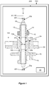
figure 1 est une vue schématique en coupe longitudinale d'un premier mode de réalisation d'une pièce d'horlogerie comprenant un premier mode de réalisation d'un dispositif horloger. - La
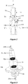
figure 2 est une vue en coupe longitudinale d'un premier composant du premier mode de réalisation du dispositif horloger. - La
figure 3 est une vue en perspective du premier mode de réalisation du dispositif horloger. - La
figure 4 est une vue en coupe longitudinale du premier mode de réalisation du dispositif horloger, le dispositif étant disposé dans un posage, lors de son procédé de réalisation, en particulier lors de la déformation plastique du premier composant. - La
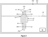
figure 5 est une vue schématique en coupe longitudinale d'un deuxième mode de réalisation d'une pièce d'horlogerie comprenant un deuxième mode de réalisation d'un dispositif horloger. - La
figure 6 est une vue schématique en coupe longitudinale d'un troisième mode de réalisation d'une pièce d'horlogerie comprenant un troisième mode de réalisation d'un dispositif horloger. - Un premier mode de réalisation d'une pièce d'horlogerie 100 est décrit ci-après en référence aux
figures 1 à 4 . La pièce d'horlogerie peut être une montre, en particulier une montre-bacelet. - La pièce d'horlogerie comprend un mouvement horloger 200. De préférence, ce mouvement horloger est un mouvement mécanique, en particulier un mouvement automatique.
- Le mouvement horloger 200 comprend un dispositif horloger 100 monté mobile en rotation relativement à un bâti 99 du mouvement.
- Le dispositif horloger 100 comprend :
- un premier composant 10 comprenant au moins une portion 12a, 12b plastiquement déformable, et
- un deuxième composant 20 doté d'une surface 24, notamment une surface de révolution et/ou de guidage et/ou de fixation du premier composant relativement au deuxième composant.
- Le premier composant est fixé à demeure sur le deuxième composant par déformation plastique de l'au moins une portion 12a, 12b à l'encontre du deuxième composant, dans un plan perpendiculaire ou sensiblement perpendiculaire à un axe A2 de ladite surface 24 du deuxième composant.
- De préférence, le deuxième composant 20 est également doté d'un élément 23a, 23b de guidage et/ou de fixation du dispositif horloger 100 relativement au mouvement horloger, en particulier relativement au bâti 99 du mouvement horloger.
- Dans ce premier mode de réalisation, le dispositif horloger 100 est un balancier 100 d'un oscillateur 101 du type balancier-spiral. L'oscillateur comprend le balancier et un spiral 40. Le balancier est donc monté mobile en rotation dans des paliers rapportés dans le bâti 99 du mouvement horloger.
- Par « balancier », on entend ici un balancier assemblé, c'est-à-dire un ensemble comprenant au moins un volant d'inertie 30 et un axe 20 de balancier.
- Le balancier ou balancier assemblé comprend ici un premier composant se présentant sous la forme d'un plateau 10, ainsi qu'un deuxième composant se présentant sous la forme d'un axe 20 de balancier.
- L'axe 20 de balancier a, pour axe géométrique, l'axe A2. Cet axe A2 est l'axe de révolution de l'axe de balancier, notamment de la surface 24 de l'axe 20 de balancier.
- Le balancier ou balancier assemblé présente ici la spécificité de comprendre le plateau 10 qui est fixé sur l'axe 20 de balancier non pas par chassage comme cela est connu de l'art antérieur, mais par sertissage, à savoir par déformation plastique de l'au moins une portion 12a, 12b du plateau 10 à l'encontre de l'axe 20 de balancier, dans un plan perpendiculaire ou sensiblement perpendiculaire à l'axe 20 de balancier, en particulier à l'axe A2 de révolution de l'axe 20 de balancier, notamment de la surface 24 de l'axe 20 de balancier.
- Le balancier 100 comprend un plateau 10 qui chemise ou recouvre l'axe 20 de balancier sur quasiment l'entier de sa hauteur. Par exemple, le plateau 10 recouvre l'axe 20 sur toute sa longueur à l'exception des pivots, et éventuellement à l'exception des tigerons. Alternativement, le plateau peut chemiser ou recouvrir une portion plus réduite de l'axe. De préférence, le plateau chemise ou recouvre une portion d'au moins 50%, voire au moins 70%, de la longueur totale de l'axe 20.
- Le plateau 10 présente une structure tubulaire comprenant une ouverture 11 traversante d'axe A1 au sein de laquelle l'axe 20 de balancier est prévu pour se loger. Ce plateau 10 comprend en outre au moins une portion 12a, 12b de moindre résistance mécanique qui est apte à être déformée plastiquement par un outil adapté, par exemple une pince. Sur la
figure 2 , le plateau est représenté avant sa déformation plastique permettant sa fixation sur l'axe 20. - Une fois le plateau 10 assemblé, notamment fixé, sur l'axe 20 de balancier, l'axe A1 est parallèle à l'axe A2, en particulier coïncidant avec l'axe A2.
- Le plateau 10 peut comprendre également une portion 13 de réception du volant d'inertie 30.
- Le plateau 10 peut comprendre également une portion 14 de réception d'une virole 40 d'un ressort-spiral (non représenté).
- Le plateau 10 peut comprendre également une portion 15 se présentant sous la forme d'un disque comprenant une cheville 16.
- Préférentiellement, le volant d'inertie 30 est assemblé par chassage sur la portion 13 de réception.
- Préférentiellement, la virole 40 est assemblée par chassage sur la portion 14 de réception.
- Préférentiellement encore, la portion 15 est venue de matière du plateau 10, c'est-à-dire que le plateau et la portion 15 sont monoblocs. Alternativement, la portion 15 pourrait être rapportée sur le plateau, par exemple par chassage.
- L'épaisseur e12 de paroi du plateau 10 au niveau de l'au moins une portion 12a, 12b est sensiblement inférieure à celle de l'épaisseur e13 de paroi au niveau de la portion 13 de réception. En particulier :
- e12 < e13/2 ;
et/ou - e12 < 0.2 mm, voire e12 < 0.15 mm, voire e12 < 0.12 mm.
- Préférentiellement, le plateau 10 comprend deux portions 12a, 12b de moindre résistance mécanique, qui sont disposées de part et d'autre de la portion 13 de réception du volant d'inertie 30 le long de l'axe A1.
- Tout ou partie de ces portions 12a, 12b est apte à être déformée plastiquement à l'encontre de l'axe 20, dans un plan perpendiculaire ou sensiblement perpendiculaire à l'axe A1 ou à l'axe A2.
- Chacune des portions 12a, 12b peut, par exemple, être déformée plastiquement de manière ponctuelle. Plus particulièrement, la portion 12a, 12b peut comprendre, dans l'ouverture 11, des saillies ou des bosses induites par des déformations plastiques localisées du matériau constitutif de la portion 12a, 12b autour de l'axe A1 ou de l'axe A2.
- Préférentiellement, le matériau de la portion 12a, 12b peut être déformé plastiquement sur l'entier de la surface de la portion 12a, 12b, notamment sur l'entier de la surface de révolution de la portion 12a, 12b. Autrement dit, la portion 12a, 12b peut faire l'objet d'un sertissage annulaire, ce qui permet de déformer plastiquement la portion 12a, 12b sur 360 degrés autour de l'axe A1 ou de l'axe A2 comme représenté sur la
figure 3 . - Les épaisseurs e12 de paroi des portions 12a, 12b peuvent être identiques. Alternativement, les épaisseurs e12 de paroi des portions 12a, 12b peuvent être différentes.
- Préférentiellement, l'axe 20, en particulier la surface 24, peut comprendre une portion 22a, 22b de réception disposée au niveau de la portion 12a, 12b lorsque l'axe est inséré au sein de l'ouverture 11 du plateau, dans laquelle le matériau déformé plastiquement au niveau de la portion 12a, 12b peut venir se loger. La portion 22a, 22b peut, par exemple, se présenter sous la forme d'une gorge ou d'une rainure s'étendant sur 360° autour de l'axe A2, notamment lorsque la portion 12a, 12b est déformée plastiquement sur 360 degrés autour de l'axe A1 ou de l'axe A2. Alternativement, la portion 22a, 22b peut s'étendre sur un angle inférieur à 360°. Chaque portion 22a, 22b, peut comprendre plusieurs parties, notamment quatre parties, équi-réparties ou non autour de l'axe A2.
- Cette rainure ou cette gorge peut présenter une section en forme de U, comme représenté sur les
figures 1 et3 . Alternativement, elle peut présenter une forme en V, ou une forme en créneau ou rectangulaire. - Avantageusement, la ou les déformations plastiques d'une ou plusieurs portions 12a, 12b permettent une tenue en couple du plateau 10 sur l'axe 20 qui est supérieure à 3 mN.m, voire supérieure à 5 mN.m. Avantageusement, la tenue en couple du plateau 10 sur l'axe 20 est suffisante pour permettre une fixation à demeure du plateau 10 sur l'axe 20, sur lequel un volant d'inertie 30 d'inertie supérieure à 5 mg.cm2, voire supérieure à 10 mg.cm2, est rapporté.
- Avantageusement, le matériau de l'axe 20 est choisi de sorte que ce dernier supporte la force de compression induite par la pince lors de l'étape de déformation plastique d'une portion 12a, 12b du plateau 10. Plus particulièrement, le matériau de l'axe 20 est choisi de sorte que l'étape de déformation plastique d'une portion 12 du plateau 10 ne vienne pas prétériter l'intégrité géométrique dudit axe.
- Avantageusement, le matériau du plateau 10, notamment de l'au moins une zone 12a, 12b, est choisi de sorte à pouvoir être déformé plastiquement. Préférentiellement, le matériau du plateau 10 est un alliage cuivreux, tel qu'un alliage CuBe2 ou un alliage CuNiSn comme un alliage CuNi15Sn8 ou « ToughMet ». Un tel alliage a pour avantage de présenter une excellente aptitude à la déformation. Sa dureté peut être de l'ordre de 250 Hv, et aller jusqu'à 400 Hv après traitement thermique.
- Préférentiellement, la dureté Vickers du matériau choisi pour le plateau 10 est de 2 à 6 fois plus petite que celle du matériau choisi pour l'axe 20.
- L'élément de guidage et/ou de fixation 23a, 23b comprend de préférence des pivots 23a, 23b, notamment des pivots ayant une géométrie de révolution d'axe A2. Ces pivots coopèrent de préférence avec des paliers prévus dans le bâti du mouvement horloger pour guider le dispositif horloger par rapport au bâti du mouvement relativement à l'axe A2.
- Un deuxième mode de réalisation d'une pièce d'horlogerie 100' est décrit ci-après en référence à la
figure 5 . La pièce d'horlogerie peut être une montre, en particulier une montre-bacelet. - La pièce d'horlogerie comprend un mouvement horloger 200'. Le mouvement horloger est un mouvement électronique ou un mouvement mécanique, en particulier un mouvement automatique.
- Le mouvement horloger 200' comprend un dispositif horloger 100' monté mobile en rotation relativement à un bâti 99' du mouvement.
- Le dispositif horloger 100' comprend :
- un premier composant 10' comprenant au moins une portion 12a', 12b' plastiquement déformable, et
- un deuxième composant 20' doté d'une surface 24', notamment une surface de révolution et/ou de guidage et/ou de fixation du premier composant relativement au deuxième composant.
- Le premier composant est fixé à demeure sur le deuxième composant par déformation plastique de l'au moins une portion à l'encontre du deuxième composant, dans un plan perpendiculaire ou sensiblement perpendiculaire à un axe A2' de ladite surface 24' du deuxième composant.
- De préférence, le deuxième composant 20' est également doté d'un élément 23a', 23b' de guidage et/ou de fixation du dispositif horloger relativement au mouvement horloger, en particulier relativement au bâti du mouvement horloger.
- Dans ce deuxième mode de réalisation, le dispositif horloger est un mobile denté 100', par exemple un mobile 100' de petite moyenne d'une chaîne de finissage du mouvement horloger.
- La structure globale du dispositif horloger reste la même que celle décrite précédemment pour le premier mode de réalisation.
- Le mobile 100' comprend, comme premier composant, un pignon 10' qui chemise ou recouvre le deuxième composant 20'. Le deuxième composant est un axe 20' de pivotement. Le pignon 10' chemise l'axe 20' de pivotement sur quasiment l'entier de sa hauteur. L'axe 20' est principalement cylindrique et lisse. Dans le cas présent, l'axe A2' est un axe de révolution du deuxième composant.
- Dans ce deuxième mode de réalisation, le pignon 10' comprend un axe A1', et deux portions 12a', 12b' de moindre résistance mécanique, qui sont disposées de part et d'autre d'une portion dentée 13' le long de l'axe A1'.
- De préférence, le pignon 10' comprend une portion de réception 14' d'une roue de petite moyenne 30'.
- Avantageusement, la ou les déformations plastiques d'une portion 12a', 12b' permettent une tenue en couple du pignon 10' sur l'axe 20' qui est suffisante pour permettre une transmission de couple entre le pignon 10' et l'axe 20', et donc pour permettre une transmission de couple entre la roue 30' et l'axe 20'.
- Avantageusement, la ou les déformations plastiques d'une portion 12a', 12b' permettent une tenue en couple du pignon 10' sur l'axe 20' qui est supérieure à 3 mN.m, voire supérieure à 5 mN.m.
- Préférentiellement, l'axe 20', en particulier la surface 24', peut comprendre une portion 22a', 22b' de réception disposée au niveau de la portion 12a', 12b' lorsque l'axe est inséré au sein d'une ouverture 11' du premier composant, dans laquelle le matériau déformé plastiquement au niveau de la portion 12a', 12b' peut venir se loger.
- Le matériau du pignon 10' peut être un acier, en particulier un acier sans plomb comme un acier Finemac. La dureté du matériau du pignon, après traitement thermique, est de l'ordre de 500 à 700 Hv. L'éventuel traitement thermique du pignon peut avoir lieu une fois le pignon 10' assemblé sur l'axe 20'. Dans ce cas, le matériau de l'axe 20' est choisi de sorte qu'il puisse supporter le traitement thermique du pignon 10'. Plus particulièrement, le matériau de l'axe 20' est choisi de sorte que l'étape de traitement thermique du pignon 10' ne vienne prétériter ni les propriétés, ni l'intégrité géométrique dudit axe.
- L'élément de guidage et/ou de fixation 23a', 23b' comprend de préférence des pivots 23a', 23b', notamment des pivots ayant une géométrie de révolution d'axe A2'. Ces pivots coopèrent de préférence avec des paliers prévus dans le bâti du mouvement horloger pour guider le dispositif horloger par rapport au bâti du mouvement relativement à l'axe A2'.
- Un troisième mode de réalisation d'une pièce d'horlogerie 100" est décrit ci-après en référence à la
figure 6 . La pièce d'horlogerie peut être une montre, en particulier une montre-bacelet. - La pièce d'horlogerie comprend un mouvement horloger 200". Le mouvement horloger est un mouvement électronique ou un mouvement mécanique, en particulier un mouvement automatique.
- Le mouvement horloger 200" comprend un dispositif horloger 100" monté mobile en rotation et en translation relativement à un bâti 99" du mouvement.
- Le dispositif horloger 100" comprend :
- un premier composant 10" comprenant au moins une portion 12a" plastiquement déformable, et
- un deuxième composant 20" doté d'une surface 24", notamment une surface de révolution et/ou de guidage et/ou de fixation du premier composant relativement au deuxième composant.
- Le premier composant est fixé à demeure sur le deuxième composant par déformation plastique de l'au moins une portion à l'encontre du deuxième composant, dans un plan perpendiculaire ou sensiblement perpendiculaire à un axe A2" de ladite surface 24" du deuxième composant.
- De préférence, le deuxième composant 20" est également doté d'un élément 23a", 23b" de guidage et/ou de fixation du dispositif horloger relativement au mouvement horloger, en particulier relativement au bâti du mouvement horloger.
- Dans ce deuxième mode de réalisation, le dispositif horloger est un mobile d'embrayage vertical 100", par exemple un mobile denté d'embrayage vertical 100".
- La structure globale du dispositif horloger reste la même que celle décrite précédemment pour les premier et deuxième modes de réalisation.
- Le mobile 100" comprend, comme premier composant, une roue 10" qui chemise partiellement le deuxième composant 20". La roue 10" peut, par exemple, comprendre une denture de chant 13". Le deuxième composant est un axe 20" de pivotement et de translation. L'axe 20" est principalement cylindrique et lisse. L'axe 20", en particulier l'élément de guidage et/ou de fixation, comprend de préférence un corps 23a" prévu pour être guidé, notamment pivoté, dans un palier du bâti 99", et une extrémité 23b" faisant office de pivot et coopérant avec une came ou une tige du mouvement 200", pour guider l'axe 20" en rotation et en translation relativement aux axes A1" et A2" respectifs de la roue 10" et de l'axe 20".
- Dans ce troisième mode de réalisation, la roue 10" comprend une seule portion 12a" de moindre résistance mécanique, qui est, par exemple, disposée à une extrémité de la roue 10" le long de l'axe A1". L'axe 20", en particulier la surface 24", peut comprendre une portion 22a" de réception disposée au niveau de la portion 12a" lorsque l'axe 20" est inséré au sein d'une ouverture 11" de la roue 10", dans laquelle le matériau déformé plastiquement peut venir se loger.
- Un mode d'exécution d'un procédé de réalisation d'un dispositif horloger 100, 100', 100" tel qu'évoqué précédemment est décrit ci-après, plus particulièrement appliqué au premier mode de réalisation. Ce procédé est applicable de manière similaire pour réaliser les deuxième et troisième modes de réalisation du dispositif horloger.
- Le procédé comprend les étapes suivantes :
- une étape de fourniture du premier composant 10, 10', 10" comprenant au moins la portion plastiquement déformable 12a, 12b ; 12a', 12b' ; 12a", en particulier une étape de mise à disposition du premier composant préalablement positionné et maintenu dans un posage 5, notamment par le biais de la portion 15 qui est guidée et maintenu en butée au sein du posage 5, comme illustré sur la
figure 4 (pour ce qui concerne le premier mode de réalisation), - une étape de fourniture du deuxième composant 20, 20', 20" doté d'une surface 24 ; 24' ; 24" notamment d'une surface de révolution et/ou d'une surface de guidage et/ou de fixation du premier composant relativement au deuxième composant, et préférentiellement d'un élément 23a, 23b ; 23a', 23b' ; 23a", 23b" de guidage et/ou de fixation du dispositif horloger relativement au mouvement,
- une étape de positionnement du premier composant relativement au deuxième composant. Dans cette étape, on insère, par exemple, le deuxième composant dans l'ouverture traversante 11 ; 11'; 11" du premier composant, jusqu'à un positionnement en butée d'un premier pivot 23a à l'encontre d'un premier palier 6a reproduisant un palier d'un mouvement horloger, notamment un palier d'une platine d'un mouvement horloger. Les diamètres d11 de l'ouverture du premier composant et d20 du corps principal ou de la surface 24 ; 24' ; 24" du deuxième composant sont choisis de telle sorte que le jeu radial entre le premier composant et le deuxième composant permet un centrage dans les tolérances requises, notamment pour un balancier et un ressort-spiral, en regard notamment des pivots 23a, 23b (pour ce qui concerne le premier mode de réalisation).
- une étape de fixation du premier composant sur le deuxième composant par déformation plastique de l'au moins une portion 12a, 12b ; 12a', 12b' ; 12a" du premier composant à l'encontre du deuxième composant, dans un plan perpendiculaire ou sensiblement perpendiculaire à l'axe A2, A2', A2" de ladite surface 24 ; 24' ; 24" du deuxième composant.
- Avantageusement, dans l'étape de positionnement, on utilise un deuxième palier 6b reproduisant un palier d'un mouvement horloger, notamment un palier d'un pont du mouvement horloger, en regard d'un deuxième pivot 23b. Dans cette configuration, les zones 12a, 12b se situent respectivement en regard des zones 22a, 22b (non visibles sur la
figure 4 ) de l'axe 20, au jeu axial près. - Avantageusement, l'étape de fixation comprend l'utilisation d'au moins une pince pour déformer plastiquement l'au moins une portion déformable plastiquement. Alternativement ou complémentairement, l'étape de fixation peut comprendre la déformation simultanée de plusieurs portions déformables. Alternativement, les pinçages des différentes zones peuvent se succéder.
- La déformation peut être réalisée par pinçage des zones 12a, 12b ; 12a', 12b' ; 12a" à l'encontre des zones 22a, 22b ; 22a', 22b' ; 22a" par le biais d'un outil 7 doté d'au moins une pince 7a, 7b.
- Optionnellement, le procédé peut comprendre une étape de traitement thermique du premier composant après l'étape de fixation.
- A l'issue des étapes mentionnées précédemment, les zones 12a, 12b ; 12a', 12b' ; 12a" du premier composant sont respectivement en contact avec les zones 22a, 22b ; 22a', 22b' ; 22a" du deuxième composant. Dans le cas du premier mode de réalisation, ceci induit une tenue en couple du plateau 10 sur l'axe 20, supérieure à 3 mN.m, voire supérieure à 5 mN.m, suffisante pour permettre une fixation à demeure du plateau 10 sur l'axe 20 lors du fonctionnement conventionnel de la pièce d'horlogerie et lors de chocs qu'est susceptible de subir la pièce d'horlogerie.
- Dans le cas du premier mode de réalisation, dans un souci de simplification de la
figure 4 , les éléments 30 et 40 ne sont pas représentés. Préférentiellement, ces éléments sont assemblés sur le premier composant 10 avant l'assemblage de ce dernier sur l'axe 20. Ainsi, le pivot 23a ne subit pas les efforts induits par l'assemblage des éléments 30 et 40 sur le premier composant 10. Alternativement, le montage du premier composant 10 sur le deuxième composant 20 peut être réalisé en amont. - Avantageusement, un tel procédé d'assemblage ne soumet pas l'axe de balancier à des forces axiales ou sensiblement axiales qui pourraient s'avérer trop conséquentes pour un axe aux dimensions horlogères, en particulier si ces forces sont prévues pour être reprises par un pivot d'axe dont les dimensions sont très sensiblement inférieures à celles du corps de l'axe. Par ailleurs, un tel procédé d'assemblage ne requiert pas d'axe fait en un matériau comprenant un domaine plastique. En ce sens, un tel procédé d'assemblage constitue une alternative particulièrement intéressante aux traditionnels procédés d'assemblage d'un composant sur un axe par chassage ou par rivetage.
- Quel que soit le mode de réalisation, l'au moins une portion plastiquement déformable est réalisée en un matériau présentant un domaine de déformation plastique. De préférence, cette au moins une portion est constituée par une portion dont la géométrie et/ou le matériau permet de réaliser une zone de moindre résistance mécanique. Cette moindre résistance mécanique permet de limiter les efforts mécaniques à exercer sur la portion lors de la déformation plastique de la portion.
- Quel que soit le mode de réalisation, le deuxième composant comprend de préférence une surface 24 ; 24' ; 24" de guidage du premier composant relativement au deuxième composant. Cette surface est de préférence un cylindre de révolution ou une ou plusieurs portions d'un cylindre de révolution. Cette surface permet donc de positionner le premier composant relativement au deuxième composant, au moins relativement à certaines directions. Cette surface coopère de préférence avec l'ouverture du premier composant pour assurer cette fonction.
- Quel que soit le mode de réalisation, le deuxième composant comprend de préférence une surface 24 ; 24' ; 24" de fixation du premier composant sur le deuxième composant. Lors de la déformation plastique du premier composant, il se forme, dans l'ouverture, un bossage, notamment un bourrelet de matière qui vient appuyer sur la surface de fixation du deuxième composant. Même après l'application de l'action de déformation du premier composant, la bosse demeure en contact contre la surface de fixation du deuxième composant du fait de la nature plastique de la déformation du premier composant. Du fait des frottements au niveau de la surface de fixation à l'interface entre le premier composant et le deuxième composant et/ou du fait d'un obstacle au niveau de la surface de fixation, des efforts tangentiels relativement aux axes A1 ; A1' ; A1" ou A2 ; A2' ; A2" peuvent être transmis d'un composant à l'autre. Par ailleurs, du fait des frottements au niveau de la surface de fixation 24 ; 24' ; 24" à l'interface entre le premier composant et le deuxième composant et/ou du fait d'un obstacle au niveau de la surface de fixation, des efforts axiaux relativement aux axes A1 ; A1' ; A1" ou A2 ; A2' ; A2" peuvent être transmis d'un composant à l'autre. Ainsi, les premier et deuxième composants sont fixés l'un à l'autre, et plus particulièrement fixés à demeure.
- Avantageusement, la surface de guidage 24 ; 24' ; 24" est une surface de révolution et/ou la surface de fixation 24 ; 24' ; 24" est une surface de révolution.
- Quel que soit le mode de réalisation, les axes A1 ; A1' ; A1" et A2 ; A2' ; A2" sont avantageusement confondus une fois le premier composant assemblé sur le deuxième composant, notamment fixé sur le deuxième composant.
- Quel que soit le mode de réalisation, la déformation plastique est avantageusement réalisée dans un plan perpendiculaire aux axes A1 ; A1' ; A1" et A2 ; A2' ; A2". Ainsi, les actions mécaniques appliquées pour réaliser la déformation sont principalement et/ou sensiblement appliquées selon des directions contenues dans ce plan. Il en résulte que la matière est principalement déformée dans ces directions et que la hauteur de la bosse ou des bosses est déterminée selon ces directions.
- Quel que soit le mode de réalisation, le deuxième composant peut être un axe 20 ; 20' ; 20" et/ou l'élément de guidage et/ou de fixation du dispositif horloger peut comprendre un ou plusieurs pivots 23a, 23b ; 23a', 23b' ; 23a", 23b", en particulier un ou plusieurs pivots d'un diamètre inférieur à 0.1 mm, voire inférieur à 0.08 mm, notamment pour le premier mode de réalisation.
- Quel que soit le mode de réalisation :
- le deuxième composant peut être fait en un matériau ne présentant pas de domaine de déformation plastique et/ou le deuxième composant est en une céramique, notamment :
- une zircone, en particulier une zircone yttriée, notamment une zircone yttriée 3%, ou
- une alumine monocristalline, ou
- une combinaison alumine-zircone,
- le deuxième composant peut présenter une dureté supérieure à 1000 Hv, voire supérieure à 1100 Hv,
et/ou - le deuxième composant peut présenter une dureté Vickers 2 à 6 fois supérieure à celle du premier composant.
- Le matériau du deuxième composant 20 ; 20' ; 20" est de préférence choisi de sorte que l'étape de déformation plastique d'une portion 12a, 12b ; 12a', 12b' ; 12a" du premier composant 10, 10', 10" ne vienne pas prétériter l'intégrité géométrique du deuxième composant. Avantageusement, le matériau du deuxième composant peut être choisi de sorte qu'une étape de traitement thermique du premier composant ne prétérite, ni les propriétés, ni l'intégrité géométrique du deuxième composant.
- De par les propriétés intrinsèques des céramiques, qui sont extrêmement dures (duretés Vickers supérieures à 1000 Hv ou comprises entre 1100 Hv et 1600 Hv), le deuxième composant 20 ne subit aucune altération lors de l'étape de déformation plastique d'une portion du premier composant. Par ailleurs, un tel matériau est particulièrement avantageux pour une fonction d'axe, notamment d'axe de balancier. En effet, l'axe peut avantageusement comprendre des pivots 23a, 23b à ses extrémités, qui sont prévus pour coopérer, notamment coopérer par contact, avec des paliers du mouvement horloger. Ces pivots peuvent comprendre un diamètre d23, différent du diamètre d20 du corps ou de la surface 24 de l'axe 20, inférieur à 0.1 mm, voire inférieur à 0.08 mm. De par les propriétés intrinsèques des céramiques citées précédemment, les pivots ne se marquent pas lors des chocs, et la performance chronométrique d'un oscillateur de type balancier-spiral comprenant un balancier selon l'invention est ainsi maintenue dans la durée. Avantageusement, en cas de choc important, ces pivots ne se déformeront pas, a contrario des pivots en acier qui peuvent plier et de ce fait porter atteinte à la chronométrie du mouvement horloger. Par ailleurs, les céramiques offrent l'avantage supplémentaire d'être particulièrement peu sensibles aux champs magnétiques, et de ne pas influencer la marche de la pièce d'horlogerie lorsqu'elle est soumise à un champ magnétique, notamment un champ magnétique supérieur à 80 kA/m (1000G).
- Quel que soit le mode de réalisation, le deuxième composant, en particulier la surface 24 ; 24' ; 24", peut comprendre au moins une portion en creux 22a, 22b ; 22a', 22b' ; 22a" notamment une gorge ou une rainure s'étendant sur tout le tour du deuxième composant ou s'étendant partiellement autour du deuxième composant, en particulier une gorge ou une rainure ayant une section en forme de U ou en forme de V ou en forme de rectangle, l'au moins une portion en creux recevant au moins en partie l'au moins une portion déformée 12a, 12b ; 12a', 12b' ; 12a" du premier composant.
- Quel que soit le mode de réalisation, l'au moins une portion plastiquement déformable peut présenter une première épaisseur e12 de paroi inférieure à une deuxième épaisseur e13 de paroi d'au moins une autre portion du premier composant ou du reste du premier composant, par exemple la première épaisseur est inférieure à la moitié de la deuxième épaisseur et/ou la première épaisseur est inférieure à 0.2 mm, voire inférieure à 0.15 mm, voire inférieure à 0.12 mm.
- Quel que soit le mode de réalisation, le couple de tenue du premier composant sur le deuxième composant autour de l'axe A2 ; A2' ; A2" peut être supérieur à 3 mN.m, voire supérieur à 5 mN.m.
- Quel que soit le mode de réalisation, l'ouverture 11 ; 11' ; 11" peut être traversante, à savoir qu'elle peut traverser de part en part le premier composant. Alternativement, cette ouverture pourrait être non traversante.
- Quel que soit le mode de réalisation, le matériau du premier composant est avantageusement choisi de sorte à pouvoir être déformé plastiquement. Le matériau du premier composant 10, 10', 10" est par exemple un alliage cuivreux, tel qu'un alliage CuBe2 ou un alliage CuNiSn comme un alliage CuNi15Sn8 ou « ToughMet ». Le matériau du premier composant 10, 10', 10" peut également être un acier sans plomb comme un acier Finemac.
- Dans les modes de réalisation décrits, le deuxième composant 20 ; 20' ; 20" est un axe de guidage en rotation à l'aide de l'élément de guidage 23a, 23b ; 23a', 23b' ; 23a" du premier composant qui est rapporté et fixé sur le deuxième composant. Complémentairement, dans le troisième mode de réalisation décrit, le deuxième composant est aussi un axe de guidage en translation à l'aide de l'élément de guidage 23b" du premier composant qui est rapporté et fixé sur le deuxième composant. Alternativement, dans un autre mode de réalisation, le deuxième composant pourrait être uniquement un axe de guidage en translation du premier composant qui est rapporté et fixé sur le deuxième composant.
- Alternativement encore, le deuxième composant pourrait comprendre un élément de fixation, en particulier une surface de fixation, du dispositif horloger. Par exemple, le deuxième composant pourrait être prévu pour être fixé, via l'élément ou la surface de fixation, sur un mouvement, notamment sur une ébauche du mouvement. Dans une telle réalisation, le dispositif horloger pourrait être complètement fixe par rapport à un bâti du mouvement.
- Quel que soit le mode de réalisation, le premier composant peut chemiser ou recouvrir au moins partiellement le deuxième composant sur quasiment l'entier de sa longueur mesurée selon les axes A1, A1', A1" ou A2, A2', A2". Par exemple, le premier composant peut chemiser ou recouvrir le deuxième composant sur toute sa longueur à l'exception de pivots, et éventuellement à l'exception de tigerons. Alternativement, le premier composant peut chemiser ou recouvrir une portion plus réduite du deuxième composant. De préférence, le premier composant peut chemiser ou recouvrir une portion d'au moins 50%, voire au moins 70%, de la longueur du deuxième composant.
- L'invention porte aussi sur un premier composant en tant que tel qui est destiné à la réalisation d'un dispositif horloger selon l'invention.
- L'invention porte encore sur un deuxième composant en tant que tel qui est destiné à la réalisation d'un dispositif horloger selon l'invention.
- Dans tout ce document, par « fixation à demeure », nous entendons une fixation permettant une tenue en couple du premier composant sur le deuxième composant qui évite tout déplacement du premier composant relativement au deuxième composant lors du fonctionnement normal de la pièce d'horlogerie. Par exemple, la tenue en couple est supérieure à 3 mN.m, voire supérieure à 5 mN.m.
- Dans tout ce document, par « déformation plastique », nous entendons indistinctement l'action ou le résultat d'une telle action.
Claims (15)
- Dispositif horloger (100 ; 100' ; 100") comprenant :- un premier composant (10 ; 10' ; 10") comprenant au moins une portion (12a, 12b ; 12a', 12b' ; 12a") plastiquement déformable, et- un deuxième composant (20 ; 20' ; 20") doté d'une surface (24 ; 24' ; 24"), notamment une surface de révolution et/ou de guidage et/ou de fixation du premier composant relativement au deuxième composant,
le premier composant étant fixé à demeure sur le deuxième composant par déformation plastique de l'au moins une portion (12a, 12b ; 12a', 12b' ; 12a") à l'encontre du deuxième composant, dans un plan perpendiculaire ou sensiblement perpendiculaire à un axe (A2 ; A2' ; A2") de ladite surface (24 ; 24' ; 24") du deuxième composant. - Dispositif horloger selon la revendication précédente, caractérisé en ce que le deuxième composant est un axe (20 ; 20' ; 20") et/ou en ce que le deuxième composant comprend un élément (23a, 23b ; 23a', 23b' ; 23a", 23b") de guidage et/ou de fixation du dispositif horloger, en particulier un ou plusieurs pivots (23a, 23b ; 23a', 23b' ; 23a", 23b"), notamment un ou plusieurs pivots d'un diamètre inférieur à 0.1 mm, voire inférieur à 0.08 mm.
- Dispositif horloger selon l'une des revendications précédentes, caractérisé en ce que le deuxième composant est en un matériau ne présentant pas de domaine de déformation plastique et/ou en ce que le deuxième composant est fait en une céramique, notamment :- une zircone, en particulier une zircone yttriée, notamment une zircone yttriée 3%, ou- une alumine monocristalline, ou- une combinaison alumine-zircone,
et/ou en ce que le deuxième composant présente une dureté supérieure à 1000 Hv, voire supérieure à 1100 Hv, ou le deuxième composant présente une dureté Vickers 2 à 6 fois supérieure à celle du premier composant. - Dispositif horloger selon l'une des revendications précédentes, caractérisé en ce que le deuxième composant, notamment la surface (24 ; 24' ; 24"), comprend au moins une portion en creux (22a, 22b ; 22a', 22b' ; 22a"), notamment une gorge ou une rainure s'étendant sur tout le tour du deuxième composant ou s'étendant partiellement autour du deuxième composant, en particulier une gorge ou une rainure ayant une section en forme de U ou en forme de V ou en forme de rectangle, l'au moins une portion en creux recevant au moins en partie l'au moins une portion déformée (12a, 12b ; 12a', 12b' ; 12a") du premier composant.
- Dispositif horloger selon l'une des revendications précédentes, caractérisé en ce que l'au moins une portion plastiquement déformable présente une première épaisseur (e12) de paroi inférieure à une deuxième épaisseur (e13) de paroi d'au moins une autre portion du premier composant, par exemple la première épaisseur est inférieure à la moitié de la deuxième épaisseur et/ou la première épaisseur est inférieure à 0.2 mm, voire inférieure à 0.15 mm, voire inférieure à 0.12 mm.
- Dispositif horloger selon l'une des revendications précédentes, caractérisé en ce que le premier composant est un plateau de balancier, notamment un plateau chemisant ou recouvrant au moins partiellement le deuxième composant.
- Dispositif horloger selon la revendication précédente, caractérisé en ce que le plateau comprend une portion (13) de réception d'un volant d'inertie (30) et/ou une portion (14) de réception d'une virole (40) d'un ressort-spiral et/ou une portion (15) formant un disque comprenant une cheville (16).
- Dispositif horloger selon l'une des revendications 1 à 5, caractérisé en ce que le premier composant est un pignon (10'), notamment un pignon chemisant ou recouvrant au moins partiellement le deuxième composant.
- Dispositif horloger selon la revendication précédente, caractérisé en ce que le pignon comprend une portion (14') de réception d'une roue dentée (30').
- Dispositif horloger selon l'une des revendications précédentes, caractérisé en ce que le couple de tenue du premier composant sur le deuxième composant autour de l'axe (A2 ; A2' ; A2") est supérieur à 3 mN.m, voire supérieur à 5 mN.m.
- Procédé de réalisation d'un dispositif horloger (100 ; 100' ; 100") selon l'une des revendications précédentes, le procédé comprenant les étapes suivantes :- une étape de fourniture d'un premier composant (10 ; 10' ; 10") comprenant au moins une portion plastiquement déformable (12a, 12b ; 12a', 12b' ; 12a"),- une étape de fourniture d'un deuxième composant (20 ; 20' ; 20") doté d'une surface (24 ; 24' ; 24"), notamment une surface de révolution et/ou une surface de guidage et/ou de fixation du premier composant relativement au deuxième composant, et éventuellement doté d'un élément (23a, 23b ; 23a', 23b' ; 23a", 23b") de guidage et/ou de fixation du dispositif horloger,- une étape de positionnement du premier composant relativement au deuxième composant,- une étape de fixation du premier composant sur le deuxième composant par déformation plastique de l'au moins une portion (12a, 12b ; 12a', 12b' ; 12a") du premier composant à l'encontre du deuxième composant, dans un plan perpendiculaire ou sensiblement perpendiculaire à l'axe (A2 ; A2' ; A2") de ladite surface (24 ; 24' ; 24") du deuxième composant.
- Procédé selon la revendication précédente, caractérisé en ce que l'étape de fixation comprend l'utilisation d'au moins une pince pour déformer plastiquement l'au moins une portion et/ou en ce que l'étape de fixation comprend la déformation simultanée de plusieurs portions déformables.
- Dispositif horloger obtenu par la mise en oeuvre du procédé selon l'une des revendications 11 à 12.
- Mouvement horloger (200 ; 200' ; 200") comprenant un dispositif horloger selon l'une des revendications 1 à 10 ou 13, le dispositif horloger étant monté mobile en rotation et/ou en translation relativement à un bâti (99 ; 99' ; 99") du mouvement ou étant fixé au bâti (99 ; 99' ; 99") du mouvement.
- Pièce d'horlogerie (300 ; 300' ; 300"), notamment montre bracelet, comprenant un dispositif horloger (100 ; 100' ; 100") selon l'une des revendications 1 à 10 ou 13 et/ou un mouvement horloger (200 ; 200' ; 200") selon la revendication précédente.
Priority Applications (4)
| Application Number | Priority Date | Filing Date | Title |
|---|---|---|---|
| EP19176099.0A EP3742236B1 (fr) | 2019-05-23 | 2019-05-23 | Dispositif horloger comprenant un premier composant fixé sur un deuxième composant par déformation plastique |
| JP2020087830A JP7684020B2 (ja) | 2019-05-23 | 2020-05-20 | 塑性変形により第2部品へ固定された第1部品を含む時計装置 |
| US16/881,299 US12072672B2 (en) | 2019-05-23 | 2020-05-22 | Horology device comprising a first component fixed to a second component by plastic deformation |
| CN202010443673.XA CN111983911A (zh) | 2019-05-23 | 2020-05-22 | 包括通过塑性变形固定到第二部件上的第一部件的钟表装置 |
Applications Claiming Priority (1)
| Application Number | Priority Date | Filing Date | Title |
|---|---|---|---|
| EP19176099.0A EP3742236B1 (fr) | 2019-05-23 | 2019-05-23 | Dispositif horloger comprenant un premier composant fixé sur un deuxième composant par déformation plastique |
Publications (2)
| Publication Number | Publication Date |
|---|---|
| EP3742236A1 true EP3742236A1 (fr) | 2020-11-25 |
| EP3742236B1 EP3742236B1 (fr) | 2025-04-09 |
Family
ID=66647064
Family Applications (1)
| Application Number | Title | Priority Date | Filing Date |
|---|---|---|---|
| EP19176099.0A Active EP3742236B1 (fr) | 2019-05-23 | 2019-05-23 | Dispositif horloger comprenant un premier composant fixé sur un deuxième composant par déformation plastique |
Country Status (4)
| Country | Link |
|---|---|
| US (1) | US12072672B2 (fr) |
| EP (1) | EP3742236B1 (fr) |
| JP (1) | JP7684020B2 (fr) |
| CN (1) | CN111983911A (fr) |
Citations (3)
| Publication number | Priority date | Publication date | Assignee | Title |
|---|---|---|---|---|
| CH699680A2 (fr) * | 2008-10-03 | 2010-04-15 | Richemont Int Sa | Dispositif de fixation d'un mobile. |
| EP2469356A1 (fr) * | 2010-12-22 | 2012-06-27 | ETA SA Manufacture Horlogère Suisse | Assemblage d'une pièce ne comportant pas de domaine plastique |
| WO2013064390A1 (fr) | 2011-10-24 | 2013-05-10 | Rolex S.A. | Oscillateur de mouvement horloger |
Family Cites Families (10)
| Publication number | Priority date | Publication date | Assignee | Title |
|---|---|---|---|---|
| SG106600A1 (en) * | 2000-03-17 | 2004-10-29 | Ebauchesfabrik Eta Ag | Means for loading or extracting data from a portable object, such as, in particular, a timepiece |
| EP1986059A1 (fr) | 2007-04-26 | 2008-10-29 | ETA SA Manufacture Horlogère Suisse | Dispositif de pivotement d'un arbre dans une pièce d'horlogerie |
| CH704258A2 (fr) * | 2010-12-22 | 2012-06-29 | Nivarox Sa | Assemblage d'une pièce ne comportant pas de domaine plastique. |
| EP2860592B1 (fr) * | 2013-10-09 | 2023-07-05 | Nivarox-FAR S.A. | Système d'assemblage utilisant un élément de blocage élastique plan |
| JP6920027B2 (ja) * | 2015-03-17 | 2021-08-18 | ロレックス・ソシエテ・アノニムRolex Sa | 時計用リベット |
| CH711353A2 (fr) * | 2015-07-24 | 2017-01-31 | Swatch Group Res & Dev Ltd | Assemblage de pièce en matériau fragile. |
| CH711923B1 (fr) * | 2015-12-17 | 2022-07-15 | Nivarox Far Sa | Procédé de fabrication d'une pièce composite avec moyens élastiques sous contrainte, pièce composite et assortiment horloger. |
| EP3258325B1 (fr) * | 2016-06-13 | 2019-10-30 | Rolex Sa | Axe horloger |
| JP6853077B2 (ja) * | 2017-03-14 | 2021-03-31 | セイコーインスツル株式会社 | 時計部品、ムーブメントおよび時計 |
| EP3617811B1 (fr) * | 2018-09-03 | 2024-10-02 | Rolex Sa | Procédé de réalisation d'une friction par lanternage |
-
2019
- 2019-05-23 EP EP19176099.0A patent/EP3742236B1/fr active Active
-
2020
- 2020-05-20 JP JP2020087830A patent/JP7684020B2/ja active Active
- 2020-05-22 CN CN202010443673.XA patent/CN111983911A/zh active Pending
- 2020-05-22 US US16/881,299 patent/US12072672B2/en active Active
Patent Citations (3)
| Publication number | Priority date | Publication date | Assignee | Title |
|---|---|---|---|---|
| CH699680A2 (fr) * | 2008-10-03 | 2010-04-15 | Richemont Int Sa | Dispositif de fixation d'un mobile. |
| EP2469356A1 (fr) * | 2010-12-22 | 2012-06-27 | ETA SA Manufacture Horlogère Suisse | Assemblage d'une pièce ne comportant pas de domaine plastique |
| WO2013064390A1 (fr) | 2011-10-24 | 2013-05-10 | Rolex S.A. | Oscillateur de mouvement horloger |
Also Published As
| Publication number | Publication date |
|---|---|
| CN111983911A (zh) | 2020-11-24 |
| JP7684020B2 (ja) | 2025-05-27 |
| JP2020201247A (ja) | 2020-12-17 |
| US20200371476A1 (en) | 2020-11-26 |
| US12072672B2 (en) | 2024-08-27 |
| EP3742236B1 (fr) | 2025-04-09 |
Similar Documents
| Publication | Publication Date | Title |
|---|---|---|
| EP2674817B1 (fr) | Procédé de fabrication d'un arbre de barillet horloger | |
| EP2860592B1 (fr) | Système d'assemblage utilisant un élément de blocage élastique plan | |
| EP2799937B1 (fr) | Corps d'amortisseur d'un balancier d'un oscillateur d'horlogerie | |
| EP3623876A1 (fr) | Virole fendue à ouverture non circulaire | |
| EP3252542B1 (fr) | Pièce de fixation d'un ressort-spiral horloger | |
| EP2860591B1 (fr) | Système d'assemblage utilisant un élément de blocage élastique conique | |
| EP1586960A1 (fr) | Couronne pour pièce d'horlogerie avec dispositif de débrayage | |
| CH699680A2 (fr) | Dispositif de fixation d'un mobile. | |
| EP2743781B1 (fr) | Dispositif d'assemblage par verrouillage d'un emboîtement | |
| EP2798413B1 (fr) | Ressort pour mouvement horloger | |
| EP3889689B1 (fr) | Organe moteur pour pièce d'horlogerie | |
| EP3257393B1 (fr) | Vis d'assemblage de deux composants horlogers | |
| EP2798414B1 (fr) | Ressort pour mouvement horloger | |
| EP2107433A1 (fr) | Procédé d'assemblage d'une pièce sur un axe | |
| EP3742236B1 (fr) | Dispositif horloger comprenant un premier composant fixé sur un deuxième composant par déformation plastique | |
| EP3252541A1 (fr) | Pièce de fixation d'un ressort-spiral horloger | |
| CH706645A1 (fr) | Système d'accouplement solidaire d'une pièce en matériau cassant à une axe métallique. | |
| EP2869134B1 (fr) | Système de barillet pour pièce d'horlogerie | |
| CH712197A2 (fr) | Système à friction pour mouvement d'horlogerie et son procédé d'assemblage. | |
| EP4462193B1 (fr) | Mouvement horloger mécanique comprenant un mobile portant un organe d' affichage et muni d'un dispositif de freinage | |
| EP3916489A1 (fr) | Ressort d'amortisseur, corps de palier et palier pour piece d'horlogerie | |
| EP4495709A1 (fr) | Élément d affichage analogique | |
| EP4495708A1 (fr) | Système de fixation d'un élément d'affichage | |
| CH708670A2 (fr) | Système d'assemblage utilisant un élément de blocage élastique conique. | |
| CH707341A2 (fr) | Dispositif d'assemblage par verrouillage d'un emboîtement et pièce d'horlogerie comportant un tel dispositif. |
Legal Events
| Date | Code | Title | Description |
|---|---|---|---|
| PUAI | Public reference made under article 153(3) epc to a published international application that has entered the european phase |
Free format text: ORIGINAL CODE: 0009012 |
|
| STAA | Information on the status of an ep patent application or granted ep patent |
Free format text: STATUS: THE APPLICATION HAS BEEN PUBLISHED |
|
| AK | Designated contracting states |
Kind code of ref document: A1 Designated state(s): AL AT BE BG CH CY CZ DE DK EE ES FI FR GB GR HR HU IE IS IT LI LT LU LV MC MK MT NL NO PL PT RO RS SE SI SK SM TR |
|
| AX | Request for extension of the european patent |
Extension state: BA ME |
|
| STAA | Information on the status of an ep patent application or granted ep patent |
Free format text: STATUS: REQUEST FOR EXAMINATION WAS MADE |
|
| 17P | Request for examination filed |
Effective date: 20210525 |
|
| RBV | Designated contracting states (corrected) |
Designated state(s): AL AT BE BG CH CY CZ DE DK EE ES FI FR GB GR HR HU IE IS IT LI LT LU LV MC MK MT NL NO PL PT RO RS SE SI SK SM TR |
|
| RIC1 | Information provided on ipc code assigned before grant |
Ipc: G04B 17/34 20060101ALI20221026BHEP Ipc: G04B 17/32 20060101ALI20221026BHEP Ipc: G04B 15/14 20060101AFI20221026BHEP |
|
| STAA | Information on the status of an ep patent application or granted ep patent |
Free format text: STATUS: EXAMINATION IS IN PROGRESS |
|
| 17Q | First examination report despatched |
Effective date: 20221207 |
|
| P01 | Opt-out of the competence of the unified patent court (upc) registered |
Effective date: 20230530 |
|
| GRAP | Despatch of communication of intention to grant a patent |
Free format text: ORIGINAL CODE: EPIDOSNIGR1 |
|
| STAA | Information on the status of an ep patent application or granted ep patent |
Free format text: STATUS: GRANT OF PATENT IS INTENDED |
|
| INTG | Intention to grant announced |
Effective date: 20241104 |
|
| RIN1 | Information on inventor provided before grant (corrected) |
Inventor name: DUMAS, AURELIEN Inventor name: CARRENO, WILLIAM |
|
| GRAS | Grant fee paid |
Free format text: ORIGINAL CODE: EPIDOSNIGR3 |
|
| GRAA | (expected) grant |
Free format text: ORIGINAL CODE: 0009210 |
|
| STAA | Information on the status of an ep patent application or granted ep patent |
Free format text: STATUS: THE PATENT HAS BEEN GRANTED |
|
| AK | Designated contracting states |
Kind code of ref document: B1 Designated state(s): AL AT BE BG CH CY CZ DE DK EE ES FI FR GB GR HR HU IE IS IT LI LT LU LV MC MK MT NL NO PL PT RO RS SE SI SK SM TR |
|
| REG | Reference to a national code |
Ref country code: GB Ref legal event code: FG4D Free format text: NOT ENGLISH |
|
| REG | Reference to a national code |
Ref country code: CH Ref legal event code: EP |
|
| REG | Reference to a national code |
Ref country code: DE Ref legal event code: R096 Ref document number: 602019068331 Country of ref document: DE |
|
| REG | Reference to a national code |
Ref country code: IE Ref legal event code: FG4D Free format text: LANGUAGE OF EP DOCUMENT: FRENCH |
|
| PGFP | Annual fee paid to national office [announced via postgrant information from national office to epo] |
Ref country code: DE Payment date: 20250513 Year of fee payment: 7 |
|
| PGFP | Annual fee paid to national office [announced via postgrant information from national office to epo] |
Ref country code: GB Payment date: 20250521 Year of fee payment: 7 |
|
| PGFP | Annual fee paid to national office [announced via postgrant information from national office to epo] |
Ref country code: FR Payment date: 20250530 Year of fee payment: 7 |
|
| PGFP | Annual fee paid to national office [announced via postgrant information from national office to epo] |
Ref country code: CH Payment date: 20250601 Year of fee payment: 7 |
|
| REG | Reference to a national code |
Ref country code: NL Ref legal event code: MP Effective date: 20250409 |
|
| PG25 | Lapsed in a contracting state [announced via postgrant information from national office to epo] |
Ref country code: NL Free format text: LAPSE BECAUSE OF FAILURE TO SUBMIT A TRANSLATION OF THE DESCRIPTION OR TO PAY THE FEE WITHIN THE PRESCRIBED TIME-LIMIT Effective date: 20250409 |
|
| REG | Reference to a national code |
Ref country code: AT Ref legal event code: MK05 Ref document number: 1784066 Country of ref document: AT Kind code of ref document: T Effective date: 20250409 |
|
| PG25 | Lapsed in a contracting state [announced via postgrant information from national office to epo] |
Ref country code: PT Free format text: LAPSE BECAUSE OF FAILURE TO SUBMIT A TRANSLATION OF THE DESCRIPTION OR TO PAY THE FEE WITHIN THE PRESCRIBED TIME-LIMIT Effective date: 20250811 Ref country code: FI Free format text: LAPSE BECAUSE OF FAILURE TO SUBMIT A TRANSLATION OF THE DESCRIPTION OR TO PAY THE FEE WITHIN THE PRESCRIBED TIME-LIMIT Effective date: 20250409 Ref country code: ES Free format text: LAPSE BECAUSE OF FAILURE TO SUBMIT A TRANSLATION OF THE DESCRIPTION OR TO PAY THE FEE WITHIN THE PRESCRIBED TIME-LIMIT Effective date: 20250409 |
|
| REG | Reference to a national code |
Ref country code: LT Ref legal event code: MG9D |
|
| PG25 | Lapsed in a contracting state [announced via postgrant information from national office to epo] |
Ref country code: NO Free format text: LAPSE BECAUSE OF FAILURE TO SUBMIT A TRANSLATION OF THE DESCRIPTION OR TO PAY THE FEE WITHIN THE PRESCRIBED TIME-LIMIT Effective date: 20250709 Ref country code: GR Free format text: LAPSE BECAUSE OF FAILURE TO SUBMIT A TRANSLATION OF THE DESCRIPTION OR TO PAY THE FEE WITHIN THE PRESCRIBED TIME-LIMIT Effective date: 20250710 |
|
| PG25 | Lapsed in a contracting state [announced via postgrant information from national office to epo] |
Ref country code: PL Free format text: LAPSE BECAUSE OF FAILURE TO SUBMIT A TRANSLATION OF THE DESCRIPTION OR TO PAY THE FEE WITHIN THE PRESCRIBED TIME-LIMIT Effective date: 20250409 |
|
| PG25 | Lapsed in a contracting state [announced via postgrant information from national office to epo] |
Ref country code: BG Free format text: LAPSE BECAUSE OF FAILURE TO SUBMIT A TRANSLATION OF THE DESCRIPTION OR TO PAY THE FEE WITHIN THE PRESCRIBED TIME-LIMIT Effective date: 20250409 |
|
| PG25 | Lapsed in a contracting state [announced via postgrant information from national office to epo] |
Ref country code: HR Free format text: LAPSE BECAUSE OF FAILURE TO SUBMIT A TRANSLATION OF THE DESCRIPTION OR TO PAY THE FEE WITHIN THE PRESCRIBED TIME-LIMIT Effective date: 20250409 |
|
| PG25 | Lapsed in a contracting state [announced via postgrant information from national office to epo] |
Ref country code: AT Free format text: LAPSE BECAUSE OF FAILURE TO SUBMIT A TRANSLATION OF THE DESCRIPTION OR TO PAY THE FEE WITHIN THE PRESCRIBED TIME-LIMIT Effective date: 20250409 |
|
| PG25 | Lapsed in a contracting state [announced via postgrant information from national office to epo] |
Ref country code: RS Free format text: LAPSE BECAUSE OF FAILURE TO SUBMIT A TRANSLATION OF THE DESCRIPTION OR TO PAY THE FEE WITHIN THE PRESCRIBED TIME-LIMIT Effective date: 20250709 |
|
| PG25 | Lapsed in a contracting state [announced via postgrant information from national office to epo] |
Ref country code: IS Free format text: LAPSE BECAUSE OF FAILURE TO SUBMIT A TRANSLATION OF THE DESCRIPTION OR TO PAY THE FEE WITHIN THE PRESCRIBED TIME-LIMIT Effective date: 20250809 |
|
| PG25 | Lapsed in a contracting state [announced via postgrant information from national office to epo] |
Ref country code: LV Free format text: LAPSE BECAUSE OF FAILURE TO SUBMIT A TRANSLATION OF THE DESCRIPTION OR TO PAY THE FEE WITHIN THE PRESCRIBED TIME-LIMIT Effective date: 20250409 |
|
| REG | Reference to a national code |
Ref country code: DE Ref legal event code: R097 Ref document number: 602019068331 Country of ref document: DE |
|
| PG25 | Lapsed in a contracting state [announced via postgrant information from national office to epo] |
Ref country code: DK Free format text: LAPSE BECAUSE OF FAILURE TO SUBMIT A TRANSLATION OF THE DESCRIPTION OR TO PAY THE FEE WITHIN THE PRESCRIBED TIME-LIMIT Effective date: 20250409 Ref country code: SM Free format text: LAPSE BECAUSE OF FAILURE TO SUBMIT A TRANSLATION OF THE DESCRIPTION OR TO PAY THE FEE WITHIN THE PRESCRIBED TIME-LIMIT Effective date: 20250409 |
|
| PG25 | Lapsed in a contracting state [announced via postgrant information from national office to epo] |
Ref country code: LU Free format text: LAPSE BECAUSE OF NON-PAYMENT OF DUE FEES Effective date: 20250523 |
|
| PG25 | Lapsed in a contracting state [announced via postgrant information from national office to epo] |
Ref country code: CZ Free format text: LAPSE BECAUSE OF FAILURE TO SUBMIT A TRANSLATION OF THE DESCRIPTION OR TO PAY THE FEE WITHIN THE PRESCRIBED TIME-LIMIT Effective date: 20250409 |
|
| PG25 | Lapsed in a contracting state [announced via postgrant information from national office to epo] |
Ref country code: EE Free format text: LAPSE BECAUSE OF FAILURE TO SUBMIT A TRANSLATION OF THE DESCRIPTION OR TO PAY THE FEE WITHIN THE PRESCRIBED TIME-LIMIT Effective date: 20250409 |
|
| PG25 | Lapsed in a contracting state [announced via postgrant information from national office to epo] |
Ref country code: RO Free format text: LAPSE BECAUSE OF FAILURE TO SUBMIT A TRANSLATION OF THE DESCRIPTION OR TO PAY THE FEE WITHIN THE PRESCRIBED TIME-LIMIT Effective date: 20250409 Ref country code: SK Free format text: LAPSE BECAUSE OF FAILURE TO SUBMIT A TRANSLATION OF THE DESCRIPTION OR TO PAY THE FEE WITHIN THE PRESCRIBED TIME-LIMIT Effective date: 20250409 |
|
| PG25 | Lapsed in a contracting state [announced via postgrant information from national office to epo] |
Ref country code: IT Free format text: LAPSE BECAUSE OF FAILURE TO SUBMIT A TRANSLATION OF THE DESCRIPTION OR TO PAY THE FEE WITHIN THE PRESCRIBED TIME-LIMIT Effective date: 20250409 |
|
| REG | Reference to a national code |
Ref country code: BE Ref legal event code: MM Effective date: 20250531 |
|
| PG25 | Lapsed in a contracting state [announced via postgrant information from national office to epo] |
Ref country code: MC Free format text: LAPSE BECAUSE OF FAILURE TO SUBMIT A TRANSLATION OF THE DESCRIPTION OR TO PAY THE FEE WITHIN THE PRESCRIBED TIME-LIMIT Effective date: 20250409 |
|
| PLBE | No opposition filed within time limit |
Free format text: ORIGINAL CODE: 0009261 |
|
| STAA | Information on the status of an ep patent application or granted ep patent |
Free format text: STATUS: NO OPPOSITION FILED WITHIN TIME LIMIT |
|
| REG | Reference to a national code |
Ref country code: CH Ref legal event code: L10 Free format text: ST27 STATUS EVENT CODE: U-0-0-L10-L00 (AS PROVIDED BY THE NATIONAL OFFICE) Effective date: 20260218 |
|
| 26N | No opposition filed |
Effective date: 20260112 |
|
| PG25 | Lapsed in a contracting state [announced via postgrant information from national office to epo] |
Ref country code: IE Free format text: LAPSE BECAUSE OF NON-PAYMENT OF DUE FEES Effective date: 20250523 |
|
| PG25 | Lapsed in a contracting state [announced via postgrant information from national office to epo] |
Ref country code: BE Free format text: LAPSE BECAUSE OF NON-PAYMENT OF DUE FEES Effective date: 20250531 |