EP3739299B1 - Sensing of objects - Google Patents
Sensing of objects Download PDFInfo
- Publication number
- EP3739299B1 EP3739299B1 EP20183799.4A EP20183799A EP3739299B1 EP 3739299 B1 EP3739299 B1 EP 3739299B1 EP 20183799 A EP20183799 A EP 20183799A EP 3739299 B1 EP3739299 B1 EP 3739299B1
- Authority
- EP
- European Patent Office
- Prior art keywords
- sensor
- conductors
- capacitance
- pest
- grounded
- Prior art date
- Legal status (The legal status is an assumption and is not a legal conclusion. Google has not performed a legal analysis and makes no representation as to the accuracy of the status listed.)
- Revoked
Links
Images




Classifications
-
- G—PHYSICS
- G01—MEASURING; TESTING
- G01R—MEASURING ELECTRIC VARIABLES; MEASURING MAGNETIC VARIABLES
- G01R27/00—Arrangements for measuring resistance, reactance, impedance, or electric characteristics derived therefrom
- G01R27/02—Measuring real or complex resistance, reactance, impedance, or other two-pole characteristics derived therefrom, e.g. time constant
- G01R27/26—Measuring inductance or capacitance; Measuring quality factor, e.g. by using the resonance method; Measuring loss factor; Measuring dielectric constants ; Measuring impedance or related variables
- G01R27/2605—Measuring capacitance
-
- G—PHYSICS
- G01—MEASURING; TESTING
- G01D—MEASURING NOT SPECIALLY ADAPTED FOR A SPECIFIC VARIABLE; ARRANGEMENTS FOR MEASURING TWO OR MORE VARIABLES NOT COVERED IN A SINGLE OTHER SUBCLASS; TARIFF METERING APPARATUS; MEASURING OR TESTING NOT OTHERWISE PROVIDED FOR
- G01D5/00—Mechanical means for transferring the output of a sensing member; Means for converting the output of a sensing member to another variable where the form or nature of the sensing member does not constrain the means for converting; Transducers not specially adapted for a specific variable
- G01D5/12—Mechanical means for transferring the output of a sensing member; Means for converting the output of a sensing member to another variable where the form or nature of the sensing member does not constrain the means for converting; Transducers not specially adapted for a specific variable using electric or magnetic means
- G01D5/14—Mechanical means for transferring the output of a sensing member; Means for converting the output of a sensing member to another variable where the form or nature of the sensing member does not constrain the means for converting; Transducers not specially adapted for a specific variable using electric or magnetic means influencing the magnitude of a current or voltage
- G01D5/24—Mechanical means for transferring the output of a sensing member; Means for converting the output of a sensing member to another variable where the form or nature of the sensing member does not constrain the means for converting; Transducers not specially adapted for a specific variable using electric or magnetic means influencing the magnitude of a current or voltage by varying capacitance
- G01D5/2405—Mechanical means for transferring the output of a sensing member; Means for converting the output of a sensing member to another variable where the form or nature of the sensing member does not constrain the means for converting; Transducers not specially adapted for a specific variable using electric or magnetic means influencing the magnitude of a current or voltage by varying capacitance by varying dielectric
-
- G—PHYSICS
- G01—MEASURING; TESTING
- G01D—MEASURING NOT SPECIALLY ADAPTED FOR A SPECIFIC VARIABLE; ARRANGEMENTS FOR MEASURING TWO OR MORE VARIABLES NOT COVERED IN A SINGLE OTHER SUBCLASS; TARIFF METERING APPARATUS; MEASURING OR TESTING NOT OTHERWISE PROVIDED FOR
- G01D5/00—Mechanical means for transferring the output of a sensing member; Means for converting the output of a sensing member to another variable where the form or nature of the sensing member does not constrain the means for converting; Transducers not specially adapted for a specific variable
- G01D5/12—Mechanical means for transferring the output of a sensing member; Means for converting the output of a sensing member to another variable where the form or nature of the sensing member does not constrain the means for converting; Transducers not specially adapted for a specific variable using electric or magnetic means
- G01D5/14—Mechanical means for transferring the output of a sensing member; Means for converting the output of a sensing member to another variable where the form or nature of the sensing member does not constrain the means for converting; Transducers not specially adapted for a specific variable using electric or magnetic means influencing the magnitude of a current or voltage
- G01D5/24—Mechanical means for transferring the output of a sensing member; Means for converting the output of a sensing member to another variable where the form or nature of the sensing member does not constrain the means for converting; Transducers not specially adapted for a specific variable using electric or magnetic means influencing the magnitude of a current or voltage by varying capacitance
-
- A—HUMAN NECESSITIES
- A01—AGRICULTURE; FORESTRY; ANIMAL HUSBANDRY; HUNTING; TRAPPING; FISHING
- A01M—CATCHING, TRAPPING OR SCARING OF ANIMALS; APPARATUS FOR THE DESTRUCTION OF NOXIOUS ANIMALS OR NOXIOUS PLANTS
- A01M1/00—Stationary means for catching or killing insects
- A01M1/02—Stationary means for catching or killing insects with devices or substances, e.g. food, pheronones attracting the insects
- A01M1/026—Stationary means for catching or killing insects with devices or substances, e.g. food, pheronones attracting the insects combined with devices for monitoring insect presence, e.g. termites
-
- A—HUMAN NECESSITIES
- A01—AGRICULTURE; FORESTRY; ANIMAL HUSBANDRY; HUNTING; TRAPPING; FISHING
- A01M—CATCHING, TRAPPING OR SCARING OF ANIMALS; APPARATUS FOR THE DESTRUCTION OF NOXIOUS ANIMALS OR NOXIOUS PLANTS
- A01M23/00—Traps for animals
-
- A—HUMAN NECESSITIES
- A01—AGRICULTURE; FORESTRY; ANIMAL HUSBANDRY; HUNTING; TRAPPING; FISHING
- A01M—CATCHING, TRAPPING OR SCARING OF ANIMALS; APPARATUS FOR THE DESTRUCTION OF NOXIOUS ANIMALS OR NOXIOUS PLANTS
- A01M23/00—Traps for animals
- A01M23/38—Electric traps
-
- A—HUMAN NECESSITIES
- A01—AGRICULTURE; FORESTRY; ANIMAL HUSBANDRY; HUNTING; TRAPPING; FISHING
- A01M—CATCHING, TRAPPING OR SCARING OF ANIMALS; APPARATUS FOR THE DESTRUCTION OF NOXIOUS ANIMALS OR NOXIOUS PLANTS
- A01M31/00—Hunting appliances
- A01M31/002—Detecting animals in a given area
-
- G—PHYSICS
- G01—MEASURING; TESTING
- G01R—MEASURING ELECTRIC VARIABLES; MEASURING MAGNETIC VARIABLES
- G01R35/00—Testing or calibrating of apparatus covered by the other groups of this subclass
Definitions
- This invention relates to a fringe capacitance sensor for sensing objects, particularly, but not exclusively, pests, a sensor unit comprising one or more fringe capacitance sensors, a system comprising a plurality of sensor units in a mesh topology or other wireless network and a method for intelligently detecting object activity, such as the presence of a pest, for example, a rodent or crawling, burrowing or flying insect.
- EP283142 discloses a pest monitoring system and teaches the use of sensing devices responsive to changes in, for example, pressure, temperature, smell, sound and/ or capacitance.
- US6937156 discloses a sensor system including at least two sensor electrodes and a capacitance sensing circuit. It teaches that when a non-capacitive object having a higher dielectric constant than air, such as a pest, approaches two spaced sensor electrodes, the capacitance between the two sensor electrodes increases, thus providing a signal that the pest has entered the area being monitored. This type of sensor does not use fringe capacitance, and thus has limitations. By way of contrast, and as illustrated in e.g.
- fringe capacitance is measured as a sensor conductor is approached (or moved away from) by an object e.g. a pest.
- a preferred sensor for facilitating this is one which has un-grounded conductors on either side of a sensor conductor, as per the preferred embodiment of the first aspect of the invention. Other sensor types may however be used.
- a further related sensor unit is known from US 7 839 282 B1 .
- An object of the present invention is to provide a more versatile and intelligent sensor, sensor unit, system and method of sensing objects, particularly, though not exclusively pests such as rodents, crawling insects, flying insects and even animals that burrow or cause damage underground, such as termites.
- Fringe capacitance is of course known - see for example Texas Instruments, Application report SNOA927 December 2014 which sets out the basics of capacitive sensing and applications. This report covers the basics of the parallel plate and fringing effect within various applications. It sets out the differences between parallel plate topology and parallel finger topology, the latter of which may work under the principle of fringing capacitance.
- a shield on the backside of the main sensor and GND electrode provides directivity towards the target. Whilst many products and applications are discussed it does not identify using fringe capacitance in pest monitoring applications or indeed how such a sensor might be produced to measure direction (by e.g. making a sensor with spaced apart triplets) or tuned for a given pest.
- a real need has been identified to provide autonomous, flexible and resilient pest monitoring services for a variety of pests in many different locations and circumstances.
- a system that can greatly reduce or eliminate the need for manual inspection and maintenance of traps; that has the ability to collect statistical data for reports and analysis, reporting such data on demand, periodically or in real time either directly or remotely; a system not limited to any specific means of connecting to the user, i.e. it can utilize, but is not limited to, connecting via RF dongle to a PC, or via GSM/GPRS and many other wireless technologies; a system not tied to traps, that can be deployed in a plurality of environments; a system that is minimally invasive to its working environment and is easily deployed; a system that reduces the chances of false detection of pests to a minimum.
- Customers who maintain many different properties can have a standard central database for statistical analysis and report generation, or generate reports and statistics from a local or remote site.
- Using sensors with a shield or guard (See Fig 5C ) enables improved sensing by fringe capacitance by adjusting the fringe fields to be responsive to a target pest.
- a smart sensor can use a switched capacitor circuit to transfer charge from the electrode and measure the amount of charge.
- fringe capacitance is that the pests can be detected above or to the side of the electrodes allowing detection through dielectric materials.
- the prior art arrangement requires detection between two electrodes and a change of dielectric between electrodes.
- the fringe capacitance measured may derive from self-capacitance sensing or mutual capacitance sensing.
- the system operates by driving current on a pin connected to a sensor and measuring the current. The presence of a pest increases the measured capacitance.
- the system measures the capacitance between two electrodes.
- One of the electrodes is the transmit electrode (TX) and the other is the receive electrode (RX).
- TX transmit electrode
- RX receive electrode
- the sensor detects changes in fringe capacitance using mutual capacitance sensing or self-capacitance sensing. This change in capacitance is used to detect or identify an object, such as an animal or pest.
- the senor comprises electrical contacts for connection to a sensor unit comprising electronics which can measure the change in fringe capacitance using self or mutual capacitance methods.
- the sensor conductor and un-grounded conductors are made of any suitably electrically conductive material, such as, for example, copper.
- an un-grounded conductor on either side of the sensor conductor supported on an un-grounded conductive substrate which is electrically isolated from said conductors ensures a constant field such that any change in fringe capacitance by an object can be sensed and either calibrated out, in the case of debris that remains on any individual sensor, or recorded if the object leaves the sensor.
- the un-grounded conductive substrate which is electrically isolated from said conductors ensures minimum interference from underneath the sensor, which otherwise would be effected when placed on e.g. metal parts.
- the un-grounded conductive substrate which is electrically isolated from said conductors, extends significantly beyond the perimeter boundary of the conductors, the effect from interference decreases, but the sensitivity and dynamic range of the capacitance also decreases, and so ideally it extends beyond the conductors to a relatively small degree. Minimizing the distance between the sensor and the un-grounded conductive substrate which is electrically isolated from said conductors ensures better coupling and effectiveness. Sensitivity and resolution will be dependent on the width and thickness of the conductors, the distance between the conductors, and the thickness of the insulating material. Hence it is desirable to design and configure each sensor for its given use.
- the capacitance is only influenced from above, and thus the sensor can be placed on any surface making it far more versatile than existing sensors.
- the senor takes the form of an elongate strip which can be short, in the order of 5-30cm, but which can be up to several meters in length.
- it can be the sensor in a sensor unit that is placed in a bait station or trap, but it can also be used in a less conventional manner.
- it can be placed under nonconductive bait stations or traps, around pallets, around door openings, and inside or about ducts etc. As such it is ideal for detecting rodents.
- a preferred conductor configuration for rodent detection is to run a series of sensor triplets in parallel along the length of a strip to form a sensor array. Running a series of sensors in parallel can be useful in not only detecting the presence of a rodent, or another animal, but also to track the direction of movement.
- a sensor using fringe capacitance as the means for detection can be used in a wide range of circumstances and by using different configurations sensors can be designed which can detect a range of pests (and other objects) including crawling insects, such as, but not limited to, cockroaches, and bed bugs.
- the sensor conductor is a substantially comb shaped element comprising a plurality of teeth corresponding to a plurality of sensor conductors.
- the un-grounded conductor is a second substantially comb shaped element comprising a plurality of teeth corresponding to a plurality of un-grounded conductor pairs.
- the two sensors are disposed like facing and interlocking "E"'s such that their respective teeth intersect. In this way substantially each sensor conductor (tooth) is flanked on either side by an un-grounded conductor pair (two teeth).
- the preferred sensors are flat and flexible and are more preferably encased in plastics making them durable.
- the conductors are of a width and thickness that is selected for their particular application, and are spaced from one another by an appropriate distance. The selection will depend on a number of parameters, the type of conductor, usually copper, and the intended purpose, and it will be determined by experiment on a case by case basis.
- fringe capacitance as a detection methodology, in contrast to measuring the change in dielectric when an object passes between two plates, has proved surprisingly effective in obtaining accurate measurements and reducing false positives, and thus is particularly beneficial in pest management.
- Sensors adapted to detect or monitor rodents including but not limited to rats and mice, and insects including, but not limited to crawling insects such as cockroaches and bedbugs are particularly sought after.
- a rodent sensor can be made with both a copper sensor and two copper un-grounded conductors, each with a width of about 3mm and a thickness of about 0.05mm, more specifically 0.06 mm, the distance between the sensor and the ungrounded wire on either side being about 2.5mm, more specifically 2.54mm and the wires can be run for up to 5 meters.
- the senor comprises at least two and preferably at least three sensor triplets (un-grounded conductor - sensing conductor - un-grounded conductor).
- a sensor unit comprising a housing containing a power source, at least one microprocessor, non-volatile memory, a transceiver, a clock and a connector operatively connecting a sensor that measures a change ( ⁇ ) in fringe capacitance (A), tuned to detect a given animal, thereto.
- Tuning the sensor unit allows the unit to not only detect but also be capable of identifying and discriminating between animals, particularly pests.
- the sensor unit has additional detection or recording means, such as, for example a camera.
- the sensor unit further comprises an inductive coil for re-charging the battery.
- a particular advantage obtained using the sensor unit of the invention is that it utilises its microprocessor to continuously, or intermittently, recalibrate a baseline capacitance. Thus, it is better able to distinguish between real positive detection events and a false positive event where, for example, debris or environmental conditions or a non-target animal might otherwise trigger a positive reading.
- Another advantage of the sensor unit of the invention is its use of a power management system to conserve power usage. Indeed, detection using fringe capacitance conserves battery usage in contrast to detection using conventional dielectric capacitance sensors which require power to detect a change in capacitance.
- the sensor unit of the invention may be incorporated into a trap or bait station or may be used in isolation in a "smart" detector system.
- a system comprising a plurality of sensor units of the second aspect of the invention disposed in a mesh topology or other wireless network.
- the system communicates via radiofrequency (rf).
- rf radiofrequency
- the network is self- healing.
- the system feeds into a central node so data collection and data dissemination can be controlled centrally.
- system comprises a bait station and / or trap fitted with a sensor unit according to the second aspect of the invention.
- system and the sensor units forming part thereof can be interrogated via a mobile device.
- a method of sensing an animal using a capacitance sensor wherein detection is determined by measuring a change in fringe capacitance.
- the change in fringe capacitance is detected when an object (typically a pest) moves towards or away from the sensor conductor between the un-grounded conductors. As it approaches the sensor conductor the capacitance increases and as it moves away from the sensor conductor the capacitance drops.
- an object typically a pest
- the method employs a capacitance sensor or sensor array comprising at least two sensor triplets, in which case the method can detect not only the presence of an object but also its direction of movement.
- the direction of movement is determined from the timed sequential triggering of at least two triplets.
- the methodology is able to detect both the arrival and departure of a pest by virtue of changes to capacitance and is configured to signal presence based on a departure.
- a sensor unit for intelligently detecting the presence of an animal comprises:
- the sensor unit comprises at least two, and more preferably three, adjacent capacitance sensors thereby forming a sensor array.
- a method of intelligently detecting an animals activity at a capacitance sensor comprising the steps of:
- the methodology is repeated at a second adjacent sensor such that a direction of travel can be determined.
- the sensor units and system monitors servicing compliance and maintenance activities recording details such as, for example, when components are replaced.
- the sensors of the invention have a number of benefits. There flexible nature means they can be placed on uneven surfaces and bent around or over objects. They can also be placed in both a vertical and horizontal orientation around, for example, a door casement or ducting.
- the encasing the sensor By encasing the sensor it can be made biohazard and chemical resistant to agents such as animal or pest urine and harsh cleaning chemicals. It will also operate effectively when wet or dirty and can be placed onto metal cableways or over mains voltage power cables.
- the sensor units can be hermetically sealed and be provided with internal batteries that can be re-charged by inductive charging or other contact charging systems ensuring a single charge can enable up to six months of extended use.
- the sensor units can be placed inside of sheet metal ducting, so long as there exists a vent or grill in the duct for radio frequency waves to propagate.
- each sensor unit can act as a range extender or data repeater as well as a detector and transmitter, eliminating the need for bespoke range extenders.
- the system is preferably adaptive, so that when no base node is detected by a single sensor unit or the entire mesh, the mesh or isolated (stand-alone) sensor unit automatically goes into an event storage mode. If a mesh or stand-alone sensor unit in event storage mode then detects the presence of a valid base node, it will then begin reporting to the base node.
- This increases system resilience and flexibility, such as allowing a technician, or other pest management personnel, with a handheld or portable device to visit multiple stand-alone sensor units and receive reports, or for the system to adapt to and recover from the loss of a section of the mesh network without major data loss.
- the sensors ability to detect if a constant 'presence' alert occurs.
- the sensor can discriminate false positives and can detect a positive event even if significant debris or liquid accumulates on the sensor.
- the process of continuously sensing and recalibrating the sensor also allows baseline recalibration to account for the gradual removal of such accumulation, such as liquids evaporating or dust being removal by air currents. This process is time dependent and it is of significance that the sensor unit bases detection on a combination of arrival and departure.
- the preferred sensors comprise a plurality of sensor triplets, and the system may be set up to require successive matching of readings in order to obtain a valid reading.
- a sensor Whilst a sensor will always register the arrival and presence of an object a significant difference with the sensor of the present invention is that it instead focuses on the departure of the detected object from the sensor's detection area. Debris will tend to accumulate and remain within the sensor's detection area for a relatively long period of time, typically until removed during routine maintenance. Pests will pass into and exit from the sensor's detection area. By ensuring that a detected arrival is followed by a detected exit this mitigates the number of false positive events.
- the time period in which the arrival and departure events must occur in order to trigger a pest detection event is adjustable and less than those time periods related to the recalibration cycle.
- the use of multiple adjacent sensors also increases the discrimination between pest activity and other activity and facilitates the sensing of movement direction. For example, a first sensor trips for arrival of a pest, then trips for departure of the pest. Next an adjacent second sensor trips for the arrival of the pest, then trips for the departure of the pest. This sequence of events indicates motion and direction. Physical sensor spacing is used to discriminate between a moving pest and other non-pest activity. This spacing is targeted to the pest type.
- the unique nature of the sensor allows the direction of travel of the pest to be captured, recorded and transmitted
- Pest Control Organisations can use the system to reduce management costs and obtain more meaningful data, further informing subsequent actions.
- the sensors of the invention may comprise a flat flexible cable or a conductively printed flexible circuit board or a rigid printed circuit board.
- the sensors can be easily removed and replaced by a technician or field operative.
- Each sensor unit can be provided with a unique identifier on a RF network, and each RF mesh network can be uniquely identified. This allows for multiple system deployments within the same location, perhaps by different PCO's in a shared building.
- a unique over the air code prefix and encryption system prevents interference with reported results by other equipment transmitting on the same RF frequency (i.e. smart meters, remote control lighting etc.)
- the systems inherent flexibility also allows for its use to monitor shipments of goods from origin to destination. This is accomplished by placing sensor units within, or around the shipment whether in a truck, van, or shipping container. When the sensing units are not connected through the RF mesh network to a base unit, PC or uplink point, they detect, timestamp, and store events until such time as a base unit, PC or uplink point's presence is detected. Thus, if pest events are detected during transit of a shipment of goods, they can be correlated by time, to a particular point in the shipment process. This would allow accurate determination of an event i.e. transfer from container to local van, after which pest events occur, and so allows for a correct and accurately targeted response to the pest issue.
- an imaging device incorporated into the body of the sensor unit can be triggered to provide a digital image of the detected pest for absolute identification. This image is then transmitted along with the other information or stored for later transmission.
- the system preferably comprises a number of remote sensing devices that are linked by a resilient, self-healing, radio frequency, mesh topology network. They are designed such that they can not only be retrofitted within existing pest bait stations and traps but also, uniquely, they allow for the monitoring of a variety of other locations such as, but not limited to, perimeters, ceiling spaces, hallways, doorways, pallets and shipping containers.
- Floor tough sensor units can also be used to monitor doorways, and in combination with either other sensors or settings, can discriminate between rodents and humans. The monitors do not need to be associated with a trap or bait station to function as detectors.
- the system allows for the remote detection and monitoring of a variety of animals, be they vertebrates, such as rodents, or invertebrates, such as insects. Although, typically, it will be deployed to detect and monitor those species that are classed as a pest it is not limited to these.
- the system continuously monitors the status of individual devices present on the mesh network and can report on devices that may fail or have failed.
- the system is able to automatically detect and record events such as the replacement of consumable items such as glue boards, fluorescent tubes and pest bait. It can also identify that an area or a pest control product has been serviced or inspected manually.
- the system also features periodic, triggered or timed reporting of stored data.
- the flexible system can report wirelessly to a PC or laptop using, for example, GPRS, Satellite modem, ADSL line or standard telephone land line.
- the system obviates the need to manually inspect every location in order to verify a pest presence or to determine the status of monitored products within the system.
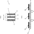
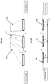
- the sensor (10) can detect changes ( ⁇ ) in fringe capacitance (A) and comprises a sensor conductor (12) flanked on either side (16a; 16b), in a spaced relationship, (da; db) by two un-grounded conductors (14a; 14b).
- the three conductors form a triplet (14a-12-14b) and are supported on an un-grounded conductive substrate (18) which is electrically isolated (20) from said conductors (12, 14a, 14b) and its surroundings.
- the sensor conductor and un-grounded conductors are both of a conductive material, typically copper, and may be in the form of wires or pads which are seated, though electrically isolated, on a conductive substrate (18), typically aluminium, which shields the sensor from the surface on which it is placed.
- a conductive substrate typically aluminium
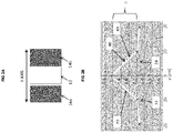
- the sensor which detects changes ( ⁇ ) in capacitance acts as a fringe capacitor detecting changes in capacitance as an object approaches (22) or moves away from (24) the sensor conductor (12) as it traverses the y-axis from the first flanking un-grounded conductor (14a) to the second flanking un-grounded conductor (14b).
- a rat passes across the sensor a change in capacitance ( ⁇ ) occurs as illustrated in Fig 2b , first increasing (22) and then decreasing (24).
- the sensitivity of the sensor is dependent on a number of factors including the materials used in making the triplet (14a-12-14b), their width (w), thickness (t), and the spacing (da and db) between the sensor conductor (12) and the un-grounded conductors (14a, 14b), as well as the nature of the conductive structure (18;20) forming the shielding support.
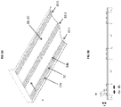
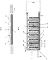
- an exemplary sensor (10), suitable for detecting rats, is illustrated in Fig 3a and 3b . It takes the form of an elongate strip which is 100mm wide and can be up to several meters in length. It, in fact, comprises an array of three sensors (10-1; 10-2; and 10-3). The three sensors are identical, and each comprises a triplet (14a-12-14b). In this embodiment each conductor of the triplet is a copper strip with a width (w) of about 2mm, and a thickness (t) of about 0.05mm.
- the sensor conductor (12) is spaced by a distance (da; db) of about 3mm from each un-grounded conductor (14a; 14b), which are inset about 5mm from the edge of the electrically isolated supporting substrate (18; 20), which is of aluminium (18) coated or encased in an insulating plastic (20). Each triplet is spaced from each other (dc) by about 27mm.
- the whole sensor is encased in a protective plastics membrane.
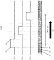
- Fig 4 illustrates the type of read out obtained when a rat traverses the sensor (10) of Fig 3a in the direction of arrow Y.
- a first sensor (10-1) there is an initial increase in capacitance, a rising edge event (22) as it approaches sensor conductor (12) from un-grounded conductor (14a) and then a falling edge event (24) as it departs sensor conductor (12) and approaches un-grounded conductor (14b).
- a rising edge event (22) as it approaches sensor conductor (12) from un-grounded conductor (14a)
- a falling edge event (24) as it departs sensor conductor (12) and approaches un-grounded conductor (14b).
- a second sensor (10-2) one sees the same, and the same is true at a third sensor (10-3), assuming of course the rat travels in the one direction as indicated by arrow Y.
- the three sensor signals provide information that can be used to provide information not only on presence (detection) of the rat, but also on its direction of movement (50), speed, and when used in a bait station, its hesitation/ feeding time.
- the sensors operate by measuring the capacitance tens of times per second and an algorithm compares sequential readings (26, 28, 30), e.g. current, previous, next and can continuously recalibrate the baseline, thereby reducing false positive readings.
- the system is able to differentiate a rat from, for example, a leaf or a dirty wet paw print left by an animal.
- the detection of a rising edge event (22) can be used in battery power management, such that the event detection can initiate an external interrupt causing a microprocessor (not shown) to change modes from a power saving "sleep" mode to "full power” mode.
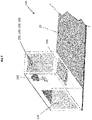
- Figs 5a to 5c help explain the significance of the conductor arrangement and their positioning on an un-grounded conductive substrate (18) which is electrically isolated (20) from said conductors (12, 14a, 14b) and its surroundings.
- the substrate may include an adhesive so it can be stuck to a surface.
- Fig 5a depicts a 3 conductor sensor (14a-12-14b) with no shield and un-grounded parallel conductors.
- 'C' is 'ghost' capacitance caused by the simple volume of copper, its inductance and overall resistance at the frequency used to interrogate the sensor.
- Fig 5b depicts the 3 conductor sensor with an earthed shield and un-grounded parallel conductors - undesirable. Capacitance values 'A' are desired, but 'B' values are undesirable;
- Fig 5c depicts the 3 conductor sensor with an un-earthed shield (18; 20) a sensor conductor (12) and a pair of un-grounded parallel conductors (14a, 14b) (as the invention).
- the resulting capacitance is mostly 'A' (desired) with no ghost capacitance (undesirable).
- a further advantage arising from the fact the sensor is shielded on its underside is that it can be placed on multiple surface types, including metal surfaces.
- the sensor construction also means that slow or persistent changes to the overall level of the fringe field can be calibrated away. This means liquid, debris or accumulated dirt will not stop the operation of the sensor.
- the dynamic range of the sensor is controlled by the ratio of the thickness (t) of the flat copper conductors to the spacing (da; db) between the un-grounded conductors (14a; 14b) in comparison to the sensing conductor (12).
- This allows various sensor configurations to be used to detect pests of varying size, from e.g. bedbugs to rats (or even larger animals, including humans).
- the sensor activates ONLY when an object interferes with the fringe field, which according to the invention is made directional by the un-grounded parallel conductors (14a, 14b) and the shielding from the un-grounded conductive substrate (18) which is electrically isolated (20). This gives a very sharp response from the sensor.
- Applicant detects the entry (70) of a pest into a fringe field, and more importantly detects the exit (80) of the pest from the field ( Fig 2b ).
- the physical layout of at least two and preferably three or more sensors allows a sensor unit to additionally detect the direction of travel (50) of a pest over the sensor, adding valuable additional information to the customer.
- a sensor unit By setting an alert/ alarm to trigger only in response to e.g. multiple events (e.g. activity at 10-1 and 10-2) within a controlled period of time (s) set by the system, false positive readings can be significantly reduced.
- the overall combination of these properties provides highly reliable detection in various environments and also facilitates the detection of the direction of motion of the pest.
- fringe capacitance also facilitates a reduction in power (and vastly increased battery life) by allowing the processor and RF mesh to be dormant when there is no activity.
- a sensor with a different configuration may be desirable.
- One such suitable configuration is described with reference to Fig 6 .
- the sensor conductor (12) is a substantially comb shaped element in which the teeth (12a, 12b, 12c...) of the comb function as a plurality of sensor conductors (12).
- the un-grounded conductor (14) is a substantially comb shaped element in which pairs of teeth (14a; 14b) flank each sensor conductor (12a; 12b) etc.
- the respective sensor conductor and un-grounded conductor are disposed like facing and interlocking "E"'s. These are electrically isolated on an ungrounded conductive substance (not shown) in the manner indicated in Fig 5C .
- the sensor strips are narrower (about 14mm in the exemplified strip).
- the conductor sensor has a width of about 2mm
- the un-grounded sensor has a width of about 2mm
- the spaced distance (da, db) between the two is about 1mm. Again the thickness of both sensors is about 0.05mm.
- the sensor unit comprises a housing (110), which contains a power source (120), and a circuit board comprising a microprocessor (130), non-volatile memory (140), a transceiver (150), and a clock (160).
- the unit also has a connector (not visible) for connecting the sensor (10) thereto.
- the sensor unit has a camera (180) such as an infrared camera with IR led 'flash'.
- the power source is preferably a high capacity, wide temperature range, battery and the sensor unit includes an inductive coil (190) for battery charging.
- the non-volatile memory acts as a sensor controller and the transceiver includes a radio frequency unit.
- the sensor (10) is in the form of a strip with electrical contacts thereon (not shown) facilitating easy connection.
- the sensor units (100) are ideally suited for integration into a networked system (200), most preferably a mesh topology network (210).
- Fig 8 illustrates a simple system (200) employing three sensor units (100) which feed data (220) to a central node (230) in this case a PC.
- the PC is connected to the internet and can be accessed by a remote monitor (240).
- Fig 9 illustrates how a sensor unit (100) of the invention can integrate into a radio frequency (RF) mesh network (210).
- RF radio frequency
- Each sensor unit (100) (numbered 1-6 in this Fig) will attempt to link directly to the central node PC (230). If this fails the unit will search for other units in range, and send them a message indicating its status. As the other units in range will also do this, the unit seeking to link will either receive one, several or no messages indicating the status of all 'in range' units. If no messages are received, the unit will go into stand-alone mode. If it receives a message from a 'linked' unit, it will send a message to be forwarded to the central node.
- RF radio frequency
- the central node can determine from the content of all received messages, the topography of the mesh. The central node will then transmit 'route instructions' to all units on the mesh. These instructions will route all traffic by e.g. the following rules, SPF - Shortest Path First, and AEP - Alternate Equal Paths.
- unit 1 will send messages via unit 2 and 3 alternately, when unit 3 receives messages from unit 1, it will always send them via unit 4 to the central node.
- unit 2 When unit 2 receives messages from unit 1 it will alternate sending via units 4 and 5. This method helps to evenly distribute message sending, using the fewest number of units possible, thus extending overall battery life.
- the mesh is designed to be easily deployed, and to self-heal if links are lost or blocked. If the link between units 1 and 2 is lost, unit 1 switches to the link to unit 3, and reports the 'loss of link' between unit 1 and unit 2 to the central node. During normal operation, unit 2 would not use a link between units 2 and 3, but if the links between 2 and 4 and 2 and 5 are lost, the link will become active. If unit 4 loses its direct link to the central node, it will activate the link between unit 4 and unit 5. As long as there is a path to the central node, any unit connected to this path via a chain of any other units, will be able to report to the central node. Nodes with the correct ID can be instantly deployed into the mesh, which will re-map its topography automatically. If there is a disconnected unit or a break in the mesh after deployment, the central node will report this.
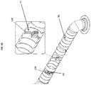
- Figure 10 illustrates an example deployment of a sensor unit (100) within an air duct (90), showing a sensor deployed around the entire inner surface (92) of the duct, and another around the outside surface (94). Even if the ducting is made of metal the sensor technology is such that it still operates correctly.
- the unit can remain part of a RF mesh network, external to the ducting, on condition that for metal ducting it is placed within range of a grill or air outlet.
- Fig 11 illustrates the deployment of the sensor units (100) to monitor goods (96) on a pallet (98).
- the sensor units (100) can be placed on or around goods and the length and flexible nature of the sensor (10) itself means the sensor can be wrapped around items.
- Fig 12 illustrates sensor units (100), numbered 1-7 and a system set up in a building shared by three different companies. Each company has a flexible rodent monitoring system installed. These are three independent designated mesh networks (designated a, b, and c as the suffix to the sensor unit).
- the RF meshes (a, b or c) are independent of each other.
- the RF mesh network protocol means that the meshes do not interfere with each other. "Mesh a" activity will not cause "mesh b" or “mesh c" to 'wake up' from power saving mode or uplink to a third party central node (230).
Landscapes
- Life Sciences & Earth Sciences (AREA)
- Pest Control & Pesticides (AREA)
- Engineering & Computer Science (AREA)
- Insects & Arthropods (AREA)
- Wood Science & Technology (AREA)
- Zoology (AREA)
- Environmental Sciences (AREA)
- Physics & Mathematics (AREA)
- General Physics & Mathematics (AREA)
- Catching Or Destruction (AREA)
- Investigating Or Analyzing Materials By The Use Of Electric Means (AREA)
- Switches That Are Operated By Magnetic Or Electric Fields (AREA)
- Geophysics And Detection Of Objects (AREA)
Priority Applications (2)
| Application Number | Priority Date | Filing Date | Title |
|---|---|---|---|
| EP22197438.9A EP4184124B1 (en) | 2016-06-03 | 2017-06-02 | Sensing of objects |
| EP25196516.6A EP4646929A2 (en) | 2016-06-03 | 2017-06-02 | Sensing of objects |
Applications Claiming Priority (3)
| Application Number | Priority Date | Filing Date | Title |
|---|---|---|---|
| GB1609756.0A GB2550967A (en) | 2016-06-03 | 2016-06-03 | Sensing of objects |
| EP17751821.4A EP3465098B1 (en) | 2016-06-03 | 2017-06-02 | Sensing of objects |
| PCT/IB2017/000678 WO2017208068A1 (en) | 2016-06-03 | 2017-06-02 | Sensing of objects |
Related Parent Applications (1)
| Application Number | Title | Priority Date | Filing Date |
|---|---|---|---|
| EP17751821.4A Division EP3465098B1 (en) | 2016-06-03 | 2017-06-02 | Sensing of objects |
Related Child Applications (3)
| Application Number | Title | Priority Date | Filing Date |
|---|---|---|---|
| EP22197438.9A Division EP4184124B1 (en) | 2016-06-03 | 2017-06-02 | Sensing of objects |
| EP22197438.9A Division-Into EP4184124B1 (en) | 2016-06-03 | 2017-06-02 | Sensing of objects |
| EP25196516.6A Division EP4646929A2 (en) | 2016-06-03 | 2017-06-02 | Sensing of objects |
Publications (2)
| Publication Number | Publication Date |
|---|---|
| EP3739299A1 EP3739299A1 (en) | 2020-11-18 |
| EP3739299B1 true EP3739299B1 (en) | 2022-11-02 |
Family
ID=56508048
Family Applications (4)
| Application Number | Title | Priority Date | Filing Date |
|---|---|---|---|
| EP20183799.4A Revoked EP3739299B1 (en) | 2016-06-03 | 2017-06-02 | Sensing of objects |
| EP25196516.6A Pending EP4646929A2 (en) | 2016-06-03 | 2017-06-02 | Sensing of objects |
| EP17751821.4A Active EP3465098B1 (en) | 2016-06-03 | 2017-06-02 | Sensing of objects |
| EP22197438.9A Active EP4184124B1 (en) | 2016-06-03 | 2017-06-02 | Sensing of objects |
Family Applications After (3)
| Application Number | Title | Priority Date | Filing Date |
|---|---|---|---|
| EP25196516.6A Pending EP4646929A2 (en) | 2016-06-03 | 2017-06-02 | Sensing of objects |
| EP17751821.4A Active EP3465098B1 (en) | 2016-06-03 | 2017-06-02 | Sensing of objects |
| EP22197438.9A Active EP4184124B1 (en) | 2016-06-03 | 2017-06-02 | Sensing of objects |
Country Status (18)
| Country | Link |
|---|---|
| US (4) | US10932459B2 (pl) |
| EP (4) | EP3739299B1 (pl) |
| JP (3) | JP7250522B2 (pl) |
| KR (1) | KR102462191B1 (pl) |
| CN (1) | CN109690256B (pl) |
| AU (1) | AU2017275843B2 (pl) |
| CA (1) | CA3026389A1 (pl) |
| DK (2) | DK3739299T3 (pl) |
| ES (2) | ES2823298T3 (pl) |
| GB (3) | GB2550967A (pl) |
| MX (2) | MX387441B (pl) |
| MY (1) | MY191415A (pl) |
| PL (2) | PL3465098T3 (pl) |
| RU (1) | RU2744117C2 (pl) |
| SA (1) | SA518400550B1 (pl) |
| SG (1) | SG11201810436TA (pl) |
| WO (1) | WO2017208068A1 (pl) |
| ZA (1) | ZA201900016B (pl) |
Families Citing this family (31)
| Publication number | Priority date | Publication date | Assignee | Title |
|---|---|---|---|---|
| GB2550967A (en) * | 2016-06-03 | 2017-12-06 | Brandenburg (Uk) Ltd | Sensing of objects |
| ES3000679T3 (en) | 2016-10-12 | 2025-03-03 | Commw Scient Ind Res Org | Arthropod detection |
| US20210169065A1 (en) * | 2017-01-06 | 2021-06-10 | Bayer Cropscience Lp | Sensor for a wireless animal trap detection system |
| WO2019010365A1 (en) | 2017-07-07 | 2019-01-10 | Basf Corporation | PEST ANIMAL MONITORING SYSTEM WITH CONDUCTIVE ELECTRODES |
| DE102018204773A1 (de) | 2018-03-28 | 2019-10-02 | BSH Hausgeräte GmbH | Haushaltsgerätetür mit einem Seitenwandelement und Verfahren zu einer Montage |
| GB2575126B (en) * | 2018-06-28 | 2020-11-11 | Bare Conductive Ltd | Differential pest sensor |
| GB201810670D0 (en) * | 2018-06-28 | 2018-08-15 | Bare Conductive Ltd | Sensor and electrical connector |
| EP4344540A3 (en) * | 2018-06-29 | 2024-08-14 | Smart Wave Technologies, Inc. | Pest control system having event monitoring |
| JP2020048439A (ja) * | 2018-09-25 | 2020-04-02 | ノバルス株式会社 | 害虫検知装置 |
| GB2578312B (en) * | 2018-10-22 | 2022-02-23 | Brandenburg Uk Ltd | Rodent trap and rodent management |
| GB2578313B (en) * | 2018-10-22 | 2021-10-13 | Brandenburg Uk Ltd | Intelligent trap and consumables |
| US10897887B1 (en) | 2018-10-22 | 2021-01-26 | Bell Laboratories, Inc. | Remote sensing rodent bait station tray |
| US11864548B1 (en) | 2018-10-22 | 2024-01-09 | Bell Laboratories, Inc. | Remote sensing repeating rodent trap |
| CA3119067A1 (en) * | 2018-11-09 | 2020-05-14 | Ecolab Usa Inc. | System and method for pest monitoring and notification |
| DE102018221960B3 (de) * | 2018-12-17 | 2020-03-26 | Siemens Healthcare Gmbh | Detektionsvorrichtung und Verfahren zum Detektieren einer Atembewegung, Computerprogramm, computerlesbares Speichermedium und medizinisches Gerät |
| WO2020160025A1 (en) * | 2019-01-30 | 2020-08-06 | Bayer Cropscience Lp | Animal trap detection system using a glue board |
| US10743523B1 (en) | 2019-03-06 | 2020-08-18 | Honeywell International Inc. | Pet monitoring system |
| DK180372B1 (en) * | 2019-04-23 | 2021-02-12 | Sensora Aps | An apparatus and method for detecting, monitoring and/or controlling of rat activity |
| CN111007113B (zh) * | 2019-11-22 | 2020-09-01 | 湖南城市学院 | 一种金属氧化物半导体气体传感器结构优化设计方法 |
| TWI708559B (zh) * | 2019-11-27 | 2020-11-01 | 廣達電腦股份有限公司 | 捕蟲裝置及其計數方法 |
| US12158559B2 (en) * | 2020-11-19 | 2024-12-03 | Ecolab Usa Inc. | Pest detection using sensor with textured surface |
| CN112858390B (zh) * | 2020-12-31 | 2022-11-15 | 云谷(固安)科技有限公司 | 异物测试装置和异物测试方法 |
| US11602144B2 (en) * | 2021-04-20 | 2023-03-14 | Fumigation Service & Supply, Inc. | System and method for retrofitting rodent traps for remote monitoring |
| KR102677191B1 (ko) * | 2021-09-29 | 2024-06-19 | 박은덕 | 멀티 해충 센싱용 장치 |
| JP7711932B2 (ja) * | 2021-10-25 | 2025-07-23 | 国立大学法人 新潟大学 | センサ素子及び撮像素子 |
| USD1108334S1 (en) | 2022-10-20 | 2026-01-06 | Rock Solid Industries International (Pty) Ltd. | Side glass |
| USD1037095S1 (en) | 2022-10-20 | 2024-07-30 | Rock Solid Industries International (Pty) Ltd. | Glass slider |
| CN118849537A (zh) * | 2023-04-26 | 2024-10-29 | 魏桥纺织股份有限公司 | 一种电容式柔性滑动传感器及其制备方法 |
| US20250085452A1 (en) * | 2023-09-13 | 2025-03-13 | Ecolab Usa Inc. | Method and apparatus for cockroach monitoring |
| WO2025174949A1 (en) * | 2024-02-13 | 2025-08-21 | Ecolab Usa Inc. | Method and apparatus for detecting pests using low power capacitive sensing |
| CN119096954A (zh) * | 2024-08-27 | 2024-12-10 | 浙江瀚达环境科技有限公司 | 一种白蚁检测装置 |
Citations (13)
| Publication number | Priority date | Publication date | Assignee | Title |
|---|---|---|---|---|
| WO1996007966A1 (en) | 1994-09-02 | 1996-03-14 | Synaptics, Inc. | Object position detector with edge motion feature |
| US6937156B2 (en) | 2002-03-29 | 2005-08-30 | Ecolab Inc. | Method and apparatus for capacitively sensing pests |
| US20070236356A1 (en) | 2006-03-29 | 2007-10-11 | Jingxi Zhang | Method and apparatus for tracking a laboratory animal location and movement |
| US20090223115A1 (en) | 2005-08-30 | 2009-09-10 | Ecolab Inc. | Bed bug monitor |
| US7839282B1 (en) | 2006-12-27 | 2010-11-23 | The United States Of America As Represented By The United States Department Of Energy | Capacitance probe for detection of anomalies in non-metallic plastic pipe |
| US20140111019A1 (en) | 2012-10-19 | 2014-04-24 | Witricity Corporation | Foreign object detection in wireless energy transfer systems |
| US20140115950A1 (en) | 2012-10-26 | 2014-05-01 | T. Eric Chornenky | Apparatus and method for safe insect extermination |
| US20140239984A1 (en) | 2013-02-25 | 2014-08-28 | Motorola Mobility Llc | Capacitive Sensor |
| US20140239982A1 (en) | 2013-02-25 | 2014-08-28 | Motorola Mobility Llc | Wearable Device with Capacitive Sensor and Method of Operation Therefor |
| US20140292351A1 (en) | 2011-06-29 | 2014-10-02 | Artem Ivanov | Capacitive Sensor Device and Method for Calibrating a Capacitive Sensor Device |
| US8919211B1 (en) | 2012-04-17 | 2014-12-30 | Alarm.Com Incorporated | Force-sensitive occupancy sensing technology |
| WO2015143633A1 (en) | 2014-03-26 | 2015-10-01 | Intel Corporation | Capacitive sensor action in response to proximity sensor data |
| WO2016073429A1 (en) | 2014-11-04 | 2016-05-12 | Dow Agrosciences Llc | Pest control system and method of operating same |
Family Cites Families (50)
| Publication number | Priority date | Publication date | Assignee | Title |
|---|---|---|---|---|
| JPS5536722A (en) * | 1978-09-07 | 1980-03-14 | Nippon Kokan Kk <Nkk> | Instrument for measuring ratio of component in composite material |
| CH648929A5 (fr) * | 1982-07-07 | 1985-04-15 | Tesa Sa | Dispositif de mesure capacitif de deplacement. |
| JPH0656308B2 (ja) * | 1985-09-30 | 1994-07-27 | 株式会社クボタ | 粉粒体の流れ検出器 |
| GB8704375D0 (en) | 1987-02-25 | 1987-04-01 | Rentokil Ltd | Pest monitoring system |
| JPH0758328B2 (ja) * | 1992-09-04 | 1995-06-21 | クリンテック株式会社 | ゴキブリ検知装置 |
| JPH0662362U (ja) * | 1993-02-02 | 1994-09-02 | 佑治 山下 | 静電容量形センサ用検知電極 |
| US5512836A (en) * | 1994-07-26 | 1996-04-30 | Chen; Zhenhai | Solid-state micro proximity sensor |
| US5801307A (en) * | 1995-07-12 | 1998-09-01 | Netzer; Yishay | Differential windshield capacitive moisture sensors |
| JP3453962B2 (ja) * | 1995-10-31 | 2003-10-06 | 松下電工株式会社 | 静電容量型雨センサ |
| FR2752052B1 (fr) * | 1996-08-02 | 1998-10-30 | Magneti Marelli France | Dispositif de mesure capacitif |
| JP3937531B2 (ja) * | 1997-10-29 | 2007-06-27 | 松下電工株式会社 | タッチスイッチ |
| JP2000048694A (ja) * | 1998-07-27 | 2000-02-18 | Omron Corp | 静電容量形近接センサ |
| JP3246726B2 (ja) * | 1998-11-13 | 2002-01-15 | 株式会社ミツトヨ | 静電容量式変位検出器及び測定装置 |
| JP3994558B2 (ja) * | 1998-12-08 | 2007-10-24 | 三菱電機株式会社 | 監視警戒装置 |
| DE19926372C2 (de) * | 1999-06-10 | 2001-06-13 | Freudenberg Carl Fa | Einrichtung zur Erkennung von Undichtheiten an Membranen |
| JP3067306U (ja) * | 1999-09-09 | 2000-03-31 | 陳 世明 | 携帯電話の充電装置 |
| US7109726B2 (en) * | 2001-07-25 | 2006-09-19 | Koninklijke Philips Electronics N.V. | Object sensing |
| ES2265111T3 (es) * | 2002-03-29 | 2007-02-01 | Ecolab, Inc. | Procedimiento y aparato para generar informes automaticos desde trampas para animales dañinos y para registrar datos adicionales de parametros de las trampas. |
| GB2407016A (en) * | 2003-10-14 | 2005-04-20 | Rentokil Initial Uk Ltd | Pest detection apparatus |
| JP3956369B2 (ja) * | 2004-02-16 | 2007-08-08 | 本田技研工業株式会社 | 静電容量型センサ |
| US20050219951A1 (en) * | 2004-04-02 | 2005-10-06 | Walton Charles A | Finding underground animals using transducer probes |
| JP2007071718A (ja) * | 2005-09-07 | 2007-03-22 | Asmo Co Ltd | 雨滴センサ、雨滴検出装置及び車両用ワイパ装置 |
| US7395161B2 (en) * | 2006-02-10 | 2008-07-01 | David Thomas A | Polymodal biological detection system |
| JP4570640B2 (ja) | 2007-03-30 | 2010-10-27 | 株式会社シー・アイ・シー | 有害小動物管理システム |
| NZ554311A (en) * | 2007-04-02 | 2009-10-30 | Contimo Ltd | A pest control device |
| CA2700507C (en) * | 2007-09-24 | 2018-05-29 | Bayer Healthcare Llc | Multi-region and potential test sensors, methods, and systems |
| JP5305478B2 (ja) | 2008-11-05 | 2013-10-02 | アルプス電気株式会社 | 近接センサ装置及びそれを用いた入力補助装置 |
| JP5484891B2 (ja) * | 2009-03-04 | 2014-05-07 | 株式会社ジャパンディスプレイ | 表示装置 |
| US20100241094A1 (en) * | 2009-03-20 | 2010-09-23 | Sherron Mark | Smart diaper |
| JP5391411B2 (ja) * | 2009-03-31 | 2014-01-15 | 株式会社フジクラ | 車両用障害物検出装置および歩行者保護用エアバッグ展開制御装置 |
| JP5469987B2 (ja) * | 2009-10-07 | 2014-04-16 | イカリ消毒株式会社 | センサ情報収集方法 |
| DE102009057439B4 (de) * | 2009-10-27 | 2012-09-27 | Gerd Reime | Vorrichtung und Verfahren zur fehlerfreien kapazitiven Messwerterfassung |
| US8988367B2 (en) * | 2010-02-05 | 2015-03-24 | Broadcom Corporation | Systems and methods for providing enhanced touch sensing |
| JP4629802B1 (ja) * | 2010-06-01 | 2011-02-09 | 株式会社シー・アイ・シー | 害虫検知装置 |
| US10508520B2 (en) * | 2011-10-26 | 2019-12-17 | QRI Group, LLC | Systems and methods for increasing recovery efficiency of petroleum reservoirs |
| EP2667156B1 (en) * | 2012-05-25 | 2015-10-21 | Nxp B.V. | Capacitive position sensor system |
| BR112015028315A2 (pt) * | 2013-05-14 | 2017-07-25 | Infestation Tracking Systems Pty Ltd | sistema de rastreamento de infestação, módulo de rastreamento, método de rastreamento, código de programa de computador, e, meio legível por computador |
| EP3375892B1 (en) * | 2013-12-12 | 2020-07-01 | Altratech Limited | Capacitive sensor |
| JP6405938B2 (ja) * | 2014-11-26 | 2018-10-17 | いすゞ自動車株式会社 | 診断装置及びセンサ |
| CN104516716A (zh) * | 2015-01-13 | 2015-04-15 | 深圳市亚耕电子科技有限公司 | 电子设备及其电容式感测系统、以及电容式感测系统的检测方法 |
| US10571350B2 (en) * | 2015-03-23 | 2020-02-25 | Nabtesco Corporation | Pressure sensor |
| EP3435855B1 (en) * | 2016-03-29 | 2023-05-10 | The Board of Trustees of the Leland Stanford Junior University | Proximity sensor circuits and related sensing methods |
| GB2550967A (en) * | 2016-06-03 | 2017-12-06 | Brandenburg (Uk) Ltd | Sensing of objects |
| RU2750855C2 (ru) * | 2016-12-09 | 2021-07-05 | Конинклейке Филипс Н.В. | Исполнительное устройство и способ для него |
| US10480962B2 (en) * | 2017-04-21 | 2019-11-19 | Capsule Technologies, Inc. | Electronic device including a capacitive sensor in a housing |
| US20190162689A1 (en) * | 2017-11-30 | 2019-05-30 | Liang-Chuan Liu | Biological sensing device |
| US20190324073A1 (en) * | 2018-04-19 | 2019-10-24 | Simplex Quantum Inc. | Capacitive sensor and capacitive sensor head |
| US10897887B1 (en) * | 2018-10-22 | 2021-01-26 | Bell Laboratories, Inc. | Remote sensing rodent bait station tray |
| DE102019209430A1 (de) * | 2019-06-28 | 2020-12-31 | Robert Bosch Gmbh | Sensoreinrichtung mit kapazitivem Sensor |
| US11181397B2 (en) * | 2019-11-01 | 2021-11-23 | Sensus Spectrum, Llc | High-resolution index (HRI) detector modules including capacitive sensors and related systems |
-
2016
- 2016-06-03 GB GB1609756.0A patent/GB2550967A/en not_active Withdrawn
-
2017
- 2017-06-02 SG SG11201810436TA patent/SG11201810436TA/en unknown
- 2017-06-02 EP EP20183799.4A patent/EP3739299B1/en not_active Revoked
- 2017-06-02 PL PL17751821T patent/PL3465098T3/pl unknown
- 2017-06-02 CA CA3026389A patent/CA3026389A1/en active Pending
- 2017-06-02 MX MX2018014678A patent/MX387441B/es unknown
- 2017-06-02 PL PL20183799.4T patent/PL3739299T3/pl unknown
- 2017-06-02 EP EP25196516.6A patent/EP4646929A2/en active Pending
- 2017-06-02 WO PCT/IB2017/000678 patent/WO2017208068A1/en not_active Ceased
- 2017-06-02 CN CN201780042399.1A patent/CN109690256B/zh active Active
- 2017-06-02 GB GB2004928.4A patent/GB2580831B/en active Active
- 2017-06-02 GB GB1708841.0A patent/GB2551053B/en active Active
- 2017-06-02 MY MYPI2018002041A patent/MY191415A/en unknown
- 2017-06-02 DK DK20183799.4T patent/DK3739299T3/da active
- 2017-06-02 AU AU2017275843A patent/AU2017275843B2/en active Active
- 2017-06-02 JP JP2018563072A patent/JP7250522B2/ja active Active
- 2017-06-02 US US16/306,815 patent/US10932459B2/en active Active
- 2017-06-02 ES ES17751821T patent/ES2823298T3/es active Active
- 2017-06-02 EP EP17751821.4A patent/EP3465098B1/en active Active
- 2017-06-02 KR KR1020187038210A patent/KR102462191B1/ko active Active
- 2017-06-02 ES ES20183799T patent/ES2937648T3/es active Active
- 2017-06-02 DK DK17751821.4T patent/DK3465098T3/da active
- 2017-06-02 EP EP22197438.9A patent/EP4184124B1/en active Active
- 2017-06-02 RU RU2018147299A patent/RU2744117C2/ru active
-
2018
- 2018-11-28 MX MX2021013096A patent/MX2021013096A/es unknown
- 2018-11-29 SA SA518400550A patent/SA518400550B1/ar unknown
-
2019
- 2019-01-02 ZA ZA2019/00016A patent/ZA201900016B/en unknown
-
2021
- 2021-01-21 US US17/154,730 patent/US11477975B2/en active Active
-
2022
- 2022-03-08 JP JP2022034981A patent/JP7442027B2/ja active Active
- 2022-10-14 US US17/966,126 patent/US11959779B2/en active Active
-
2023
- 2023-11-27 JP JP2023200030A patent/JP7584613B2/ja active Active
-
2024
- 2024-03-08 US US18/600,641 patent/US20240210214A1/en active Pending
Patent Citations (13)
| Publication number | Priority date | Publication date | Assignee | Title |
|---|---|---|---|---|
| WO1996007966A1 (en) | 1994-09-02 | 1996-03-14 | Synaptics, Inc. | Object position detector with edge motion feature |
| US6937156B2 (en) | 2002-03-29 | 2005-08-30 | Ecolab Inc. | Method and apparatus for capacitively sensing pests |
| US20090223115A1 (en) | 2005-08-30 | 2009-09-10 | Ecolab Inc. | Bed bug monitor |
| US20070236356A1 (en) | 2006-03-29 | 2007-10-11 | Jingxi Zhang | Method and apparatus for tracking a laboratory animal location and movement |
| US7839282B1 (en) | 2006-12-27 | 2010-11-23 | The United States Of America As Represented By The United States Department Of Energy | Capacitance probe for detection of anomalies in non-metallic plastic pipe |
| US20140292351A1 (en) | 2011-06-29 | 2014-10-02 | Artem Ivanov | Capacitive Sensor Device and Method for Calibrating a Capacitive Sensor Device |
| US8919211B1 (en) | 2012-04-17 | 2014-12-30 | Alarm.Com Incorporated | Force-sensitive occupancy sensing technology |
| US20140111019A1 (en) | 2012-10-19 | 2014-04-24 | Witricity Corporation | Foreign object detection in wireless energy transfer systems |
| US20140115950A1 (en) | 2012-10-26 | 2014-05-01 | T. Eric Chornenky | Apparatus and method for safe insect extermination |
| US20140239984A1 (en) | 2013-02-25 | 2014-08-28 | Motorola Mobility Llc | Capacitive Sensor |
| US20140239982A1 (en) | 2013-02-25 | 2014-08-28 | Motorola Mobility Llc | Wearable Device with Capacitive Sensor and Method of Operation Therefor |
| WO2015143633A1 (en) | 2014-03-26 | 2015-10-01 | Intel Corporation | Capacitive sensor action in response to proximity sensor data |
| WO2016073429A1 (en) | 2014-11-04 | 2016-05-12 | Dow Agrosciences Llc | Pest control system and method of operating same |
Non-Patent Citations (14)
| Title |
|---|
| ANNONYMOUS: "24-Bit Capacitance-to-Digital Converter with Temperature Sensor", ANALOG DEVECIS, no. AD7745/AD7746, 1 April 2005 (2005-04-01), pages 1 - 28, XP002388296 |
| ANONYMOUS: "Ultra-Low Power, 1-Channel, Capacitance Converter for Proximity Sensing AD7151", 1 January 2007 (2007-01-01), pages 1 - 28, XP093070801, Retrieved from the Internet <URL:https://www.analog.com/media/en/technical-documentation/data-sheets/AD7151.pdf> [retrieved on 20230804] |
| BAXTER, LARRY K., HERRICK, ROBERT J.: "Capacitive Sensors: Design and Applications.", 1 January 1997, IEEE, ISBN: 9780780311305, article ANONYMOUS: "Miscellaneous sensors", pages: 122 - 146, XP093097497 |
| DALE R. PATRICK, STEPHEN W. FARDO: "Industrial Electronics Devices and Systems, Second Edition", 1 January 2000, TAYLOR & FRANCIS, ISBN: 9780824705015, article DALE R. PATRICK, STEPHEN W. FARDO: "Operational Amplifiers", pages: 109 - 109, XP093097503 |
| DAVID WANG: "FDC1004: Basics of Capacitive Sensing and Applications", 1 December 2014 (2014-12-01), pages 1 - 12, XP055279836, Retrieved from the Internet <URL:http://www.ti.com/lit/an/snoa927/snoa927.pdf> [retrieved on 20160613] |
| HEIDARY A: "A Low-Cost Universal Integrated Interface for Capacitive Sensors", THESIS, 11 June 2010 (2010-06-11), pages 1 - 160, XP093070816 |
| OUH HYUN KYU, LEE JUNGWOO, HAN SANGYUN, KIM HYUNJIP, YOON INSIK, HONG SOONWON: "A programmable mutual capacitance sensing circuit for a large-sized touch panel", 2012 IEEE INTERNATIONAL SYMPOSIUM ON CIRCUITS AND SYSTEMS, 1 January 2012 (2012-01-01), pages 1395 - 1398, XP093097460, ISBN: 978-1-4673-0217-3, DOI: 10.1109/ISCAS.2012.6271504 |
| PRATT SUSAN: "Ask The Application Engineer—35, Capacitance Sensors for Human Interfaces to Electronic Equipment", 1 October 2006 (2006-10-01), pages 1 - 4, XP093070813, Retrieved from the Internet <URL:https://www.analog.com/media/en/technical-documentation/frequently-asked-questions/vol40n4.pdf> [retrieved on 20230804] |
| REN C LUO: "Sensor Technologies and Microsensor Issues for Mechatronics Systems", IEEE/ASME TRANSACTIONS ON MECHATRONICS, vol. 1, no. 1, 1 March 1996 (1996-03-01), US , pages 39 - 49., XP000588545, ISSN: 1083-4435, DOI: 10.1109/3516.491408 |
| S M HUANG , A L STOTT , R G GREEN , M S BECK: "Electronic transducers for industrial measurement of low value capacitances", JOURNAL OF PHYSICS E SCIENTIFIC INSTRUMENTS, vol. 21, no. 3, 1 March 1988 (1988-03-01), GB , pages 242 - 250, XP020018735, ISSN: 0022-3735, DOI: 10.1088/0022-3735/21/3/001 |
| SCARLETT JIM: "Using CDCs to Control Motion for Sample Aspiration", 1 January 2014 (2014-01-01), pages 1 - 6, XP093070804, Retrieved from the Internet <URL:https://www.analog.com/media/en/technical-documentation/application-notes/AN-1301.pdf> [retrieved on 20230804] |
| SHI-FENG QI ; YAN-HUA LI: "A New Wireless Sensor Used in Grain Pests Detection", CONTROL ENGINEERING AND COMMUNICATION TECHNOLOGY (ICCECT), 7 December 2012 (2012-12-07), pages 755 - 758, XP032311361, ISBN: 978-1-4673-4499-9, DOI: 10.1109/ICCECT.2012.97 |
| WANG DAVID: "Capacitive Sensing: Ins and Outs of Active Shielding", 1 February 2015 (2015-02-01), pages 1 - 13, XP093097483, Retrieved from the Internet <URL:https://www.ti.com/lit/an/snoa926a/snoa926a.pdf?ts=1698855431820&ref_url=https%253A%252F%252Fwww.bing.com%252F> [retrieved on 20231102] |
| XIAOHUI HU, WUQIANG YANG: "Planar capacitive sensors – designs and applications", SENSOR REVIEW, vol. 30, no. 1, 26 January 2010 (2010-01-26), GB , pages 24 - 39, XP055473609, ISSN: 0260-2288, DOI: 10.1108/02602281011010772 |
Also Published As
Similar Documents
| Publication | Publication Date | Title |
|---|---|---|
| US11959779B2 (en) | Sensing of objects | |
| EP3119196B1 (en) | Apparatus for sensing bed bug excretion | |
| BR112018074883B1 (pt) | Sensor, unidade de sensor, sistema, método para detectar um animal ou praga e método de detecção inteligente de uma atividade de animais ou pragas | |
| KR100880779B1 (ko) | 정전 용량 센서를 이용한 생명체 감지 시스템 및 방법 |
Legal Events
| Date | Code | Title | Description |
|---|---|---|---|
| PUAI | Public reference made under article 153(3) epc to a published international application that has entered the european phase |
Free format text: ORIGINAL CODE: 0009012 |
|
| STAA | Information on the status of an ep patent application or granted ep patent |
Free format text: STATUS: THE APPLICATION HAS BEEN PUBLISHED |
|
| AC | Divisional application: reference to earlier application |
Ref document number: 3465098 Country of ref document: EP Kind code of ref document: P |
|
| AK | Designated contracting states |
Kind code of ref document: A1 Designated state(s): AL AT BE BG CH CY CZ DE DK EE ES FI FR GB GR HR HU IE IS IT LI LT LU LV MC MK MT NL NO PL PT RO RS SE SI SK SM TR |
|
| STAA | Information on the status of an ep patent application or granted ep patent |
Free format text: STATUS: REQUEST FOR EXAMINATION WAS MADE |
|
| 17P | Request for examination filed |
Effective date: 20210517 |
|
| RBV | Designated contracting states (corrected) |
Designated state(s): AL AT BE BG CH CY CZ DE DK EE ES FI FR GB GR HR HU IE IS IT LI LT LU LV MC MK MT NL NO PL PT RO RS SE SI SK SM TR |
|
| GRAP | Despatch of communication of intention to grant a patent |
Free format text: ORIGINAL CODE: EPIDOSNIGR1 |
|
| STAA | Information on the status of an ep patent application or granted ep patent |
Free format text: STATUS: GRANT OF PATENT IS INTENDED |
|
| INTG | Intention to grant announced |
Effective date: 20220216 |
|
| GRAS | Grant fee paid |
Free format text: ORIGINAL CODE: EPIDOSNIGR3 |
|
| GRAA | (expected) grant |
Free format text: ORIGINAL CODE: 0009210 |
|
| STAA | Information on the status of an ep patent application or granted ep patent |
Free format text: STATUS: THE PATENT HAS BEEN GRANTED |
|
| AC | Divisional application: reference to earlier application |
Ref document number: 3465098 Country of ref document: EP Kind code of ref document: P |
|
| AK | Designated contracting states |
Kind code of ref document: B1 Designated state(s): AL AT BE BG CH CY CZ DE DK EE ES FI FR GB GR HR HU IE IS IT LI LT LU LV MC MK MT NL NO PL PT RO RS SE SI SK SM TR |
|
| REG | Reference to a national code |
Ref country code: GB Ref legal event code: FG4D |
|
| REG | Reference to a national code |
Ref country code: CH Ref legal event code: EP Ref country code: AT Ref legal event code: REF Ref document number: 1529052 Country of ref document: AT Kind code of ref document: T Effective date: 20221115 |
|
| REG | Reference to a national code |
Ref country code: DE Ref legal event code: R096 Ref document number: 602017063442 Country of ref document: DE |
|
| REG | Reference to a national code |
Ref country code: IE Ref legal event code: FG4D |
|
| REG | Reference to a national code |
Ref country code: DK Ref legal event code: T3 Effective date: 20230203 |
|
| REG | Reference to a national code |
Ref country code: NL Ref legal event code: FP |
|
| REG | Reference to a national code |
Ref country code: SE Ref legal event code: TRGR |
|
| REG | Reference to a national code |
Ref country code: LT Ref legal event code: MG9D |
|
| REG | Reference to a national code |
Ref country code: NO Ref legal event code: T2 Effective date: 20221102 |
|
| REG | Reference to a national code |
Ref country code: NO Ref legal event code: CHAD Owner name: CAUCUS LIMITED, GB |
|
| REG | Reference to a national code |
Ref country code: ES Ref legal event code: FG2A Ref document number: 2937648 Country of ref document: ES Kind code of ref document: T3 Effective date: 20230330 |
|
| REG | Reference to a national code |
Ref country code: AT Ref legal event code: MK05 Ref document number: 1529052 Country of ref document: AT Kind code of ref document: T Effective date: 20221102 |
|
| PG25 | Lapsed in a contracting state [announced via postgrant information from national office to epo] |
Ref country code: PT Free format text: LAPSE BECAUSE OF FAILURE TO SUBMIT A TRANSLATION OF THE DESCRIPTION OR TO PAY THE FEE WITHIN THE PRESCRIBED TIME-LIMIT Effective date: 20230302 Ref country code: LT Free format text: LAPSE BECAUSE OF FAILURE TO SUBMIT A TRANSLATION OF THE DESCRIPTION OR TO PAY THE FEE WITHIN THE PRESCRIBED TIME-LIMIT Effective date: 20221102 Ref country code: FI Free format text: LAPSE BECAUSE OF FAILURE TO SUBMIT A TRANSLATION OF THE DESCRIPTION OR TO PAY THE FEE WITHIN THE PRESCRIBED TIME-LIMIT Effective date: 20221102 Ref country code: AT Free format text: LAPSE BECAUSE OF FAILURE TO SUBMIT A TRANSLATION OF THE DESCRIPTION OR TO PAY THE FEE WITHIN THE PRESCRIBED TIME-LIMIT Effective date: 20221102 |
|
| PG25 | Lapsed in a contracting state [announced via postgrant information from national office to epo] |
Ref country code: RS Free format text: LAPSE BECAUSE OF FAILURE TO SUBMIT A TRANSLATION OF THE DESCRIPTION OR TO PAY THE FEE WITHIN THE PRESCRIBED TIME-LIMIT Effective date: 20221102 Ref country code: LV Free format text: LAPSE BECAUSE OF FAILURE TO SUBMIT A TRANSLATION OF THE DESCRIPTION OR TO PAY THE FEE WITHIN THE PRESCRIBED TIME-LIMIT Effective date: 20221102 Ref country code: IS Free format text: LAPSE BECAUSE OF FAILURE TO SUBMIT A TRANSLATION OF THE DESCRIPTION OR TO PAY THE FEE WITHIN THE PRESCRIBED TIME-LIMIT Effective date: 20230302 Ref country code: HR Free format text: LAPSE BECAUSE OF FAILURE TO SUBMIT A TRANSLATION OF THE DESCRIPTION OR TO PAY THE FEE WITHIN THE PRESCRIBED TIME-LIMIT Effective date: 20221102 Ref country code: GR Free format text: LAPSE BECAUSE OF FAILURE TO SUBMIT A TRANSLATION OF THE DESCRIPTION OR TO PAY THE FEE WITHIN THE PRESCRIBED TIME-LIMIT Effective date: 20230203 |
|
| PG25 | Lapsed in a contracting state [announced via postgrant information from national office to epo] |
Ref country code: SM Free format text: LAPSE BECAUSE OF FAILURE TO SUBMIT A TRANSLATION OF THE DESCRIPTION OR TO PAY THE FEE WITHIN THE PRESCRIBED TIME-LIMIT Effective date: 20221102 Ref country code: RO Free format text: LAPSE BECAUSE OF FAILURE TO SUBMIT A TRANSLATION OF THE DESCRIPTION OR TO PAY THE FEE WITHIN THE PRESCRIBED TIME-LIMIT Effective date: 20221102 Ref country code: EE Free format text: LAPSE BECAUSE OF FAILURE TO SUBMIT A TRANSLATION OF THE DESCRIPTION OR TO PAY THE FEE WITHIN THE PRESCRIBED TIME-LIMIT Effective date: 20221102 Ref country code: CZ Free format text: LAPSE BECAUSE OF FAILURE TO SUBMIT A TRANSLATION OF THE DESCRIPTION OR TO PAY THE FEE WITHIN THE PRESCRIBED TIME-LIMIT Effective date: 20221102 |
|
| REG | Reference to a national code |
Ref country code: DE Ref legal event code: R026 Ref document number: 602017063442 Country of ref document: DE |
|
| PLBI | Opposition filed |
Free format text: ORIGINAL CODE: 0009260 |
|
| PLAX | Notice of opposition and request to file observation + time limit sent |
Free format text: ORIGINAL CODE: EPIDOSNOBS2 |
|
| PG25 | Lapsed in a contracting state [announced via postgrant information from national office to epo] |
Ref country code: SK Free format text: LAPSE BECAUSE OF FAILURE TO SUBMIT A TRANSLATION OF THE DESCRIPTION OR TO PAY THE FEE WITHIN THE PRESCRIBED TIME-LIMIT Effective date: 20221102 Ref country code: AL Free format text: LAPSE BECAUSE OF FAILURE TO SUBMIT A TRANSLATION OF THE DESCRIPTION OR TO PAY THE FEE WITHIN THE PRESCRIBED TIME-LIMIT Effective date: 20221102 |
|
| 26 | Opposition filed |
Opponent name: ECOLAB USA INC. Effective date: 20230801 |
|
| REG | Reference to a national code |
Ref country code: BE Ref legal event code: PD Owner name: CAUCUS LIMITED; GB Free format text: DETAILS ASSIGNMENT: CHANGE OF OWNER(S), ASSIGNMENT; FORMER OWNER NAME: BRANDENBURG (UK) LIMITED Effective date: 20230908 |
|
| REG | Reference to a national code |
Ref country code: NL Ref legal event code: PD Owner name: CAUCUS LIMITED; GB Free format text: DETAILS ASSIGNMENT: CHANGE OF OWNER(S), ASSIGNMENT; FORMER OWNER NAME: BRANDENBURG (UK) LIMITED Effective date: 20231107 |
|
| REG | Reference to a national code |
Ref country code: DE Ref legal event code: R081 Ref document number: 602017063442 Country of ref document: DE Owner name: CAUCUS LTD., BRIERLEY HILL, GB Free format text: FORMER OWNER: BRANDENBURG (UK) LIMITED, BRIERLEY HILL, WEST MIDLANDS, GB |
|
| PG25 | Lapsed in a contracting state [announced via postgrant information from national office to epo] |
Ref country code: SI Free format text: LAPSE BECAUSE OF FAILURE TO SUBMIT A TRANSLATION OF THE DESCRIPTION OR TO PAY THE FEE WITHIN THE PRESCRIBED TIME-LIMIT Effective date: 20221102 |
|
| RAP2 | Party data changed (patent owner data changed or rights of a patent transferred) |
Owner name: CAUCUS LIMITED |
|
| PLBB | Reply of patent proprietor to notice(s) of opposition received |
Free format text: ORIGINAL CODE: EPIDOSNOBS3 |
|
| REG | Reference to a national code |
Ref country code: GB Ref legal event code: 732E Free format text: REGISTERED BETWEEN 20231123 AND 20231129 |
|
| PG25 | Lapsed in a contracting state [announced via postgrant information from national office to epo] |
Ref country code: MC Free format text: LAPSE BECAUSE OF FAILURE TO SUBMIT A TRANSLATION OF THE DESCRIPTION OR TO PAY THE FEE WITHIN THE PRESCRIBED TIME-LIMIT Effective date: 20221102 |
|
| PG25 | Lapsed in a contracting state [announced via postgrant information from national office to epo] |
Ref country code: MC Free format text: LAPSE BECAUSE OF FAILURE TO SUBMIT A TRANSLATION OF THE DESCRIPTION OR TO PAY THE FEE WITHIN THE PRESCRIBED TIME-LIMIT Effective date: 20221102 |
|
| PG25 | Lapsed in a contracting state [announced via postgrant information from national office to epo] |
Ref country code: BG Free format text: LAPSE BECAUSE OF FAILURE TO SUBMIT A TRANSLATION OF THE DESCRIPTION OR TO PAY THE FEE WITHIN THE PRESCRIBED TIME-LIMIT Effective date: 20221102 |
|
| PG25 | Lapsed in a contracting state [announced via postgrant information from national office to epo] |
Ref country code: BG Free format text: LAPSE BECAUSE OF FAILURE TO SUBMIT A TRANSLATION OF THE DESCRIPTION OR TO PAY THE FEE WITHIN THE PRESCRIBED TIME-LIMIT Effective date: 20221102 |
|
| PGFP | Annual fee paid to national office [announced via postgrant information from national office to epo] |
Ref country code: NL Payment date: 20241127 Year of fee payment: 8 |
|
| PGFP | Annual fee paid to national office [announced via postgrant information from national office to epo] |
Ref country code: DE Payment date: 20241128 Year of fee payment: 8 |
|
| PGFP | Annual fee paid to national office [announced via postgrant information from national office to epo] |
Ref country code: NO Payment date: 20241210 Year of fee payment: 8 |
|
| PGFP | Annual fee paid to national office [announced via postgrant information from national office to epo] |
Ref country code: DK Payment date: 20241206 Year of fee payment: 8 |
|
| PGFP | Annual fee paid to national office [announced via postgrant information from national office to epo] |
Ref country code: PL Payment date: 20241126 Year of fee payment: 8 Ref country code: BE Payment date: 20241127 Year of fee payment: 8 Ref country code: LU Payment date: 20241206 Year of fee payment: 8 |
|
| PGFP | Annual fee paid to national office [announced via postgrant information from national office to epo] |
Ref country code: GB Payment date: 20241127 Year of fee payment: 8 |
|
| PGFP | Annual fee paid to national office [announced via postgrant information from national office to epo] |
Ref country code: FR Payment date: 20241127 Year of fee payment: 8 |
|
| PGFP | Annual fee paid to national office [announced via postgrant information from national office to epo] |
Ref country code: IE Payment date: 20241127 Year of fee payment: 8 |
|
| PGFP | Annual fee paid to national office [announced via postgrant information from national office to epo] |
Ref country code: IT Payment date: 20241127 Year of fee payment: 8 Ref country code: ES Payment date: 20241127 Year of fee payment: 8 |
|
| PGFP | Annual fee paid to national office [announced via postgrant information from national office to epo] |
Ref country code: SE Payment date: 20241206 Year of fee payment: 8 |
|
| PGFP | Annual fee paid to national office [announced via postgrant information from national office to epo] |
Ref country code: CH Payment date: 20241209 Year of fee payment: 8 |
|
| PGFP | Annual fee paid to national office [announced via postgrant information from national office to epo] |
Ref country code: TR Payment date: 20241126 Year of fee payment: 8 |
|
| RDAF | Communication despatched that patent is revoked |
Free format text: ORIGINAL CODE: EPIDOSNREV1 |
|
| REG | Reference to a national code |
Ref country code: DE Ref legal event code: R103 Ref document number: 602017063442 Country of ref document: DE Ref country code: DE Ref legal event code: R064 Ref document number: 602017063442 Country of ref document: DE |
|
| RDAG | Patent revoked |
Free format text: ORIGINAL CODE: 0009271 |
|
| STAA | Information on the status of an ep patent application or granted ep patent |
Free format text: STATUS: PATENT REVOKED |
|
| REG | Reference to a national code |
Ref country code: CH Ref legal event code: PL |
|
| 27W | Patent revoked |
Effective date: 20250217 |
|
| GBPR | Gb: patent revoked under art. 102 of the ep convention designating the uk as contracting state |
Effective date: 20250217 |
|
| PG25 | Lapsed in a contracting state [announced via postgrant information from national office to epo] |
Ref country code: CY Free format text: LAPSE BECAUSE OF FAILURE TO SUBMIT A TRANSLATION OF THE DESCRIPTION OR TO PAY THE FEE WITHIN THE PRESCRIBED TIME-LIMIT; INVALID AB INITIO Effective date: 20170602 |
|
| PG25 | Lapsed in a contracting state [announced via postgrant information from national office to epo] |
Ref country code: HU Free format text: LAPSE BECAUSE OF FAILURE TO SUBMIT A TRANSLATION OF THE DESCRIPTION OR TO PAY THE FEE WITHIN THE PRESCRIBED TIME-LIMIT; INVALID AB INITIO Effective date: 20170602 |
|
| REG | Reference to a national code |
Ref country code: SE Ref legal event code: ECNC |