EP3738902A1 - Verbundener bindegurt und verriegelungsvorrichtung - Google Patents
Verbundener bindegurt und verriegelungsvorrichtung Download PDFInfo
- Publication number
- EP3738902A1 EP3738902A1 EP18899286.1A EP18899286A EP3738902A1 EP 3738902 A1 EP3738902 A1 EP 3738902A1 EP 18899286 A EP18899286 A EP 18899286A EP 3738902 A1 EP3738902 A1 EP 3738902A1
- Authority
- EP
- European Patent Office
- Prior art keywords
- ties
- positioning
- interconnected
- interval
- labelled
- Prior art date
- Legal status (The legal status is an assumption and is not a legal conclusion. Google has not performed a legal analysis and makes no representation as to the accuracy of the status listed.)
- Granted
Links
Images





Classifications
-
- B—PERFORMING OPERATIONS; TRANSPORTING
- B65—CONVEYING; PACKING; STORING; HANDLING THIN OR FILAMENTARY MATERIAL
- B65D—CONTAINERS FOR STORAGE OR TRANSPORT OF ARTICLES OR MATERIALS, e.g. BAGS, BARRELS, BOTTLES, BOXES, CANS, CARTONS, CRATES, DRUMS, JARS, TANKS, HOPPERS, FORWARDING CONTAINERS; ACCESSORIES, CLOSURES, OR FITTINGS THEREFOR; PACKAGING ELEMENTS; PACKAGES
- B65D63/00—Flexible elongated elements, e.g. straps, for bundling or supporting articles
- B65D63/10—Non-metallic straps, tapes, or bands; Filamentary elements, e.g. strings, threads or wires; Joints between ends thereof
- B65D63/1018—Joints produced by application of integral securing members, e.g. buckles, wedges, tongue and slot, locking head and teeth or the like
- B65D63/1027—Joints produced by application of integral securing members, e.g. buckles, wedges, tongue and slot, locking head and teeth or the like the integral securing member being formed as a female and male locking member, e.g. locking head and locking teeth, or the like
-
- B—PERFORMING OPERATIONS; TRANSPORTING
- B65—CONVEYING; PACKING; STORING; HANDLING THIN OR FILAMENTARY MATERIAL
- B65D—CONTAINERS FOR STORAGE OR TRANSPORT OF ARTICLES OR MATERIALS, e.g. BAGS, BARRELS, BOTTLES, BOXES, CANS, CARTONS, CRATES, DRUMS, JARS, TANKS, HOPPERS, FORWARDING CONTAINERS; ACCESSORIES, CLOSURES, OR FITTINGS THEREFOR; PACKAGING ELEMENTS; PACKAGES
- B65D63/00—Flexible elongated elements, e.g. straps, for bundling or supporting articles
- B65D63/10—Non-metallic straps, tapes, or bands; Filamentary elements, e.g. strings, threads or wires; Joints between ends thereof
- B65D63/1018—Joints produced by application of integral securing members, e.g. buckles, wedges, tongue and slot, locking head and teeth or the like
-
- B—PERFORMING OPERATIONS; TRANSPORTING
- B65—CONVEYING; PACKING; STORING; HANDLING THIN OR FILAMENTARY MATERIAL
- B65D—CONTAINERS FOR STORAGE OR TRANSPORT OF ARTICLES OR MATERIALS, e.g. BAGS, BARRELS, BOTTLES, BOXES, CANS, CARTONS, CRATES, DRUMS, JARS, TANKS, HOPPERS, FORWARDING CONTAINERS; ACCESSORIES, CLOSURES, OR FITTINGS THEREFOR; PACKAGING ELEMENTS; PACKAGES
- B65D63/00—Flexible elongated elements, e.g. straps, for bundling or supporting articles
- B65D63/10—Non-metallic straps, tapes, or bands; Filamentary elements, e.g. strings, threads or wires; Joints between ends thereof
- B65D63/1018—Joints produced by application of integral securing members, e.g. buckles, wedges, tongue and slot, locking head and teeth or the like
- B65D63/1027—Joints produced by application of integral securing members, e.g. buckles, wedges, tongue and slot, locking head and teeth or the like the integral securing member being formed as a female and male locking member, e.g. locking head and locking teeth, or the like
- B65D63/1063—Joints produced by application of integral securing members, e.g. buckles, wedges, tongue and slot, locking head and teeth or the like the integral securing member being formed as a female and male locking member, e.g. locking head and locking teeth, or the like the female locking member being provided with at least one plastic barb
-
- B—PERFORMING OPERATIONS; TRANSPORTING
- B65—CONVEYING; PACKING; STORING; HANDLING THIN OR FILAMENTARY MATERIAL
- B65B—MACHINES, APPARATUS OR DEVICES FOR, OR METHODS OF, PACKAGING ARTICLES OR MATERIALS; UNPACKING
- B65B13/00—Bundling articles
- B65B13/02—Applying and securing binding material around articles or groups of articles, e.g. using strings, wires, strips, bands or tapes
- B65B13/025—Hand-held tools
- B65B13/027—Hand-held tools for applying straps having preformed connecting means, e.g. cable ties
-
- B—PERFORMING OPERATIONS; TRANSPORTING
- B65—CONVEYING; PACKING; STORING; HANDLING THIN OR FILAMENTARY MATERIAL
- B65D—CONTAINERS FOR STORAGE OR TRANSPORT OF ARTICLES OR MATERIALS, e.g. BAGS, BARRELS, BOTTLES, BOXES, CANS, CARTONS, CRATES, DRUMS, JARS, TANKS, HOPPERS, FORWARDING CONTAINERS; ACCESSORIES, CLOSURES, OR FITTINGS THEREFOR; PACKAGING ELEMENTS; PACKAGES
- B65D85/00—Containers, packaging elements or packages, specially adapted for particular articles or materials
- B65D85/20—Containers, packaging elements or packages, specially adapted for particular articles or materials for incompressible or rigid rod-shaped or tubular articles
- B65D85/24—Containers, packaging elements or packages, specially adapted for particular articles or materials for incompressible or rigid rod-shaped or tubular articles for needles, nails or like elongate small articles
-
- F—MECHANICAL ENGINEERING; LIGHTING; HEATING; WEAPONS; BLASTING
- F16—ENGINEERING ELEMENTS AND UNITS; GENERAL MEASURES FOR PRODUCING AND MAINTAINING EFFECTIVE FUNCTIONING OF MACHINES OR INSTALLATIONS; THERMAL INSULATION IN GENERAL
- F16B—DEVICES FOR FASTENING OR SECURING CONSTRUCTIONAL ELEMENTS OR MACHINE PARTS TOGETHER, e.g. NAILS, BOLTS, CIRCLIPS, CLAMPS, CLIPS OR WEDGES; JOINTS OR JOINTING
- F16B15/00—Nails; Staples
- F16B15/08—Nails; Staples formed in integral series but easily separable
-
- B—PERFORMING OPERATIONS; TRANSPORTING
- B65—CONVEYING; PACKING; STORING; HANDLING THIN OR FILAMENTARY MATERIAL
- B65D—CONTAINERS FOR STORAGE OR TRANSPORT OF ARTICLES OR MATERIALS, e.g. BAGS, BARRELS, BOTTLES, BOXES, CANS, CARTONS, CRATES, DRUMS, JARS, TANKS, HOPPERS, FORWARDING CONTAINERS; ACCESSORIES, CLOSURES, OR FITTINGS THEREFOR; PACKAGING ELEMENTS; PACKAGES
- B65D2563/00—Flexible elongated elements, e.g. straps for bundling or supporting atricles
- B65D2563/10—Non-metallic straps, tapes or bands; Filamentary elements, e.g. strings, threads, wires; Joints between ends thereof
- B65D2563/101—Details of non-metallic straps, tapes or bands
- B65D2563/103—Details of non-metallic straps, tapes or bands details of the male locking member, e.g. locking teeth on the strap
-
- B—PERFORMING OPERATIONS; TRANSPORTING
- B65—CONVEYING; PACKING; STORING; HANDLING THIN OR FILAMENTARY MATERIAL
- B65D—CONTAINERS FOR STORAGE OR TRANSPORT OF ARTICLES OR MATERIALS, e.g. BAGS, BARRELS, BOTTLES, BOXES, CANS, CARTONS, CRATES, DRUMS, JARS, TANKS, HOPPERS, FORWARDING CONTAINERS; ACCESSORIES, CLOSURES, OR FITTINGS THEREFOR; PACKAGING ELEMENTS; PACKAGES
- B65D2563/00—Flexible elongated elements, e.g. straps for bundling or supporting atricles
- B65D2563/10—Non-metallic straps, tapes or bands; Filamentary elements, e.g. strings, threads, wires; Joints between ends thereof
- B65D2563/101—Details of non-metallic straps, tapes or bands
- B65D2563/107—Details of non-metallic straps, tapes or bands having a release mechanism, e.g. reusable bundling straps
-
- B—PERFORMING OPERATIONS; TRANSPORTING
- B65—CONVEYING; PACKING; STORING; HANDLING THIN OR FILAMENTARY MATERIAL
- B65D—CONTAINERS FOR STORAGE OR TRANSPORT OF ARTICLES OR MATERIALS, e.g. BAGS, BARRELS, BOTTLES, BOXES, CANS, CARTONS, CRATES, DRUMS, JARS, TANKS, HOPPERS, FORWARDING CONTAINERS; ACCESSORIES, CLOSURES, OR FITTINGS THEREFOR; PACKAGING ELEMENTS; PACKAGES
- B65D2563/00—Flexible elongated elements, e.g. straps for bundling or supporting atricles
- B65D2563/10—Non-metallic straps, tapes or bands; Filamentary elements, e.g. strings, threads, wires; Joints between ends thereof
- B65D2563/101—Details of non-metallic straps, tapes or bands
- B65D2563/108—Appendages formed with/on the strap for purposes other than joining, releasing or bundling, e.g. for fixing the strap to a wall, label plates
Definitions
- the present disclosure relates to a tie, and in particular to an interconnected tie assembly (or a connected tie strap) and a locking device.
- Objects to be bundled are bundled with a one-piece fixing tie and then fastened directly onto a sheet metal part by using the elastic fastener of the one-piece fixing tie.
- head features of the one-piece fixing ties mainly include: a combined type of a fir-tree-shaped head plus a disc or a fir-tree-shaped head plus wings, a combined type of an arrow head plus a disc or an arrow head plus wings, a flat-plate type with a locking hole, and so on.
- the one-piece fixing ties for both cars and household appliances are injection-molded by using plastic molds and are manually pulled out from flow channels for injection molding one by one and then put into plastic bags, and then, when in use, taken out from the plastic packaging bags one by one, and manually and individually applied to bundles.
- a labelled tie i.e., a tie with a label or tag
- the object of the present disclosure includes providing an interconnected tie assembly designed to solve the deficiencies of the traditional loose-packed one-piece fixing ties and labelled ties which are less adaptable to automatic bundling operations.
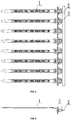
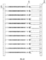
- an interconnected tie assembly comprising a main reinforcing plate, and one-piece fixing ties or labelled ties, wherein the one-piece fixing ties or the labelled ties are arranged at a fixed interval, the main reinforcing plate is perpendicular to a length direction of each of the one-piece fixing ties or the labelled ties, and a fixing head portion of at least one of the one-piece fixing ties or a label edge of at least one of the labelled ties is connected integrally with one main reinforcing plate to form a unit of interconnected ties.
- the fixing head portions of the plurality of one-piece fixing ties or the label edges of the plurality of labelled ties are connected directly to one main reinforcing plate, respectively.
- a runner is disposed between the head of each of the one-piece fixing ties or labelled ties and the main reinforcing plate.
- positioning members are provided at the two ends of the main reinforcing plate, respectively.
- the positioning member includes a positioning hole and/or a positioning column, and the positioning hole and/or the positioning column is in a circular, elliptical, or polygonal shape; or the positioning member includes a positioning rib and/or a positioning slot.
- the positioning member includes a positioning hole and a positioning column, wherein the positioning hole and the positioning column are provided at the two ends of the main reinforcing plate, respectively, and the positioning hole and the positioning column can be connected to each other in cooperation; or
- the positioning member includes a positioning rib and a positioning slot, wherein the positioning rib and the positioning slot are provided at the two ends of the main reinforcing plate, respectively, and the positioning rib and the positioning slot can be connected to each other in cooperation.
- the main reinforcing plate is provided with interval positioning holes or interval positioning columns, and a distance between two adjacent interval positioning holes or interval positioning columns is equal to the interval between two adjacent one-piece fixing ties or labelled ties in the unit of interconnected ties; or the distance between two adjacent interval positioning holes or interval positioning columns is equal to n times or 1/n times the interval between two adjacent one-piece fixing ties or labelled ties in the unit of interconnected ties, wherein n is a positive integer.
- interval positioning holes or interval positioning columns are each in a circular, elliptical, or polygonal shape.
- the interconnected tie assembly further comprises an auxiliary reinforcing plate, the auxiliary reinforcing plate is perpendicular to the length direction of each of the one-piece fixing ties or labelled ties, and the auxiliary reinforcing plate is connected to an end portion of each of the one-piece fixing ties or labelled ties.
- positioning members are provided at the two ends of the auxiliary reinforcing plate, respectively.
- the positioning member includes a positioning hole and/or a positioning column, and the positioning hole and/or the positioning column is in a circular, elliptical, or polygonal shape.
- the positioning member includes a positioning hole and a positioning column, wherein the positioning hole and the positioning column are provided at the two ends of the auxiliary reinforcing plate, respectively, and the positioning hole and the positioning column can be connected to each other in cooperation.
- the auxiliary reinforcing plate is provided with interval positioning holes or interval positioning columns, and a distance between two adjacent interval positioning holes or interval positioning columns is equal to the interval between two adjacent one-piece fixing ties or labelled ties in the unit of interconnected ties, or the distance between two adjacent interval positioning holes or interval positioning columns is equal to n times or 1/n times the interval between two adjacent one-piece fixing ties or labelled ties in the unit of interconnected ties, wherein n is a positive integer.
- interval positioning holes or interval positioning columns on the auxiliary reinforcing plate are each in a circular, elliptical, or polygonal shape.
- a plurality of units of interconnected ties are connected in an end-to-end manner to form a string or a roll.
- a further object of the present disclosure is to provide a locking device, comprising the interconnected tie assembly described in the present disclosure.
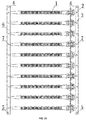
- 1-one-piece fixing tie 2-main reinforcing plate; 3-runner; 4-positioning hole; 5-positioning column; 6-auxiliary reinforcing plate; 7-interval positioning hole or interval positioning column; 8-labelled tie.
- orientation or positional relationships indicated by the terms such as “center”, “longitudinal”, “transverse”, “length”, “width”, “thickness”, “up”, “down”, “front”, “rear”, “left”, “right”, “vertical”, “horizontal”, “top”, “bottom”, “inside”, “outside”, “clockwise”, and “anticlockwise” are the orientation or positional relationships shown based on the drawings, and these terms are intended only to facilitate the description of the present disclosure and simplify the description, but not intended to indicate or imply that the referred devices or elements must be in a particular orientation, or constructed or operated in the particular orientation, and therefore should not be construed as limiting the present disclosure.
- first and second are used for descriptive purposes only, and should not be understood as an indication or implication of relative importance or an implicit indication of the number of the indicated technical features. Therefore, a feature defined with the terms “first” and “second” may explicitly or implicitly include one or more such features.
- a plurality of means two or more, unless otherwise expressly and specifically defined.
- connection may be fixed connection or detachable connection or integral connection, may be mechanical connection or electric connection, or may be direct coupling or indirect coupling via an intermediate medium or internal communication between two elements or mutual interaction between two elements.
- connection may be fixed connection or detachable connection or integral connection, may be mechanical connection or electric connection, or may be direct coupling or indirect coupling via an intermediate medium or internal communication between two elements or mutual interaction between two elements.
- a first feature "on” (or above) or “below” a second feature may include a case where the first and second features are in direct contact, and may also include a case where the first and second features are not in direct contact, but are in contact via an additional feature therebetween.
- a first feature "on”, “above”, or “over” a second feature is meant to include a case where the first feature is directly above or obliquely above the second feature, or merely means that the first feature is at a level height higher than the second feature.
- a first feature "below”, “under”, or “underneath” a second feature is meant to include a case where the first feature is directly below or obliquely below the second feature, or merely means that the first feature is at a level height lower than the second feature.
- An embodiment of the present disclosure provides an interconnected tie assembly, comprising a main reinforcing plate, and one-piece fixing ties or labelled ties, wherein the one-piece fixing ties or the labelled ties are arranged at a fixed interval, the main reinforcing plate is perpendicular to the length direction of each of the one-piece fixing ties or the labelled ties, and a fixing head portion of at least one of the one-piece fixing ties or a label edge of at least one of the labelled ties is connected integrally with one main reinforcing plate to form a unit of interconnected ties.
- the main reinforcing plate extends in a direction perpendicular to the length direction of the one-piece fixing tie or labelled tie.
- One or a plurality of one-piece fixing ties or labelled ties may be provided, and one main reinforcing plate is provided.
- a fixing head portion of at least one one-piece fixing tie or a label edge of at least one labelled tie is fixedly connected to one main reinforcing plate to form a unit of interconnected ties.
- the fixing head portion of the fixing tie or the label edge of at least one labelled tie may be connected to the main reinforcing plate by means of adhesion, or in any suitable form such as an integrally molded structure.
- the fixing head portion of at least one one-piece fixing tie or the label edge of at least one labelled tie is fixedly connected to one main reinforcing plate, deformation of the fixing head portion of the one-piece fixing tie or of the label edge of the labelled tie can be reduced, which provides a more reliable feeding mode for automatic tying operations.
- the interconnected tie assembly since the fixing head portion of at least one one-piece fixing tie or the label edge of at least one labelled tie is connected integrally with one main reinforcing plate to form a unit of interconnected ties, the interconnected tie assembly according to this embodiment is used without a vibratory bowl feeder and a material dispersing mechanism, so that an apparatus for automatic tying operation can be changed from the automatic tying apparatus to an automatic tying tool, and the apparatus can be made with a greatly reduced cost and size, and used more conveniently.
- the interconnected one-piece fixing ties or labelled ties are much less deformed because they are present in an interconnected mode from the aspects including the mold structure, manufacturing process, packaging, and sale.
- the one-piece fixing tie may consist of a tie body and a fixing head, wherein one end of the tie body is fixedly connected to the fixing head, the fixing head can secure the tie body, and the fixing head is the fixing head portion described above.
- the one-piece fixing tie may also consist of a tie body and a fastener, wherein one end of the tie body is fixedly connected to the fastener, the fastener can secure the tie body, and the fastener is the fixing head portion described above.
- the fixing head portions of the plurality of one-piece fixing ties or the label edges of the plurality of labelled ties are connected to one main reinforcing plates, respectively.
- the fixing head portions of the plurality of one-piece fixing ties or the label edges of the plurality of labelled ties are fixedly connected to one main reinforcing plate, respectively, and the fixing head portions of the plurality of one-piece fixing ties or the label edges of the plurality of labelled ties are disposed at uniform intervals along the direction of extension of the main reinforcing plate so that the one-piece fixing ties or the labelled ties are arranged at a fixed interval.
- the interconnected tie assembly comprises: a plurality of one-piece fixing ties or labelled ties and one main reinforcing plate, wherein the one-piece fixing ties or labelled ties are arranged at a fixed interval, the main reinforcing plate is perpendicular to the length direction of each of the one-piece fixing ties or labelled ties, and fixing heads of the plurality of one-piece fixing ties or label edges of the plurality of labelled ties are connected to the main reinforcing plate to form a unit of interconnected ties.
- the number of the one-piece fixing ties or labelled ties in a unit of interconnected one-piece fixing ties depends on the size(s) of the injection mold and/or the injection molding machine, but the unit of interconnected ties at least contains one one-piece fixing tie or labelled tie and one main reinforcing plate.
- the unit of interconnected ties is to be used in cooperation with an automatic tying apparatus or an automatic tying tool, the automatic tying apparatus or the automatic tying tool cuts off the one-piece fixing ties or the labelled ties individually and discharges the main reinforcing plate as waste.
- a runner is disposed between the head of each of the one-piece fixing ties or labelled ties and the main reinforcing plate.
- the runner extends in a direction parallel to the length direction of the one-piece fixing tie or labelled tie, and the runner has one end fixedly connected to the main reinforcing plate, and the other end fixedly connected to the head of the one-piece fixing tie or the labelled tie, either by means of adhesion or by a connector.
- the main reinforcing plate, the runners, and the one-piece fixing ties or labelled ties may also be made as a one-piece structure.
- flow channels are provided in the main reinforcing plate and in the runners, respectively, and the flow channels of the runners communicate with the flow channels of the main reinforcing plate. Therefore, the flow channels in the main reinforcing plate and in the runners are used as flow channels for injection molding of the one-piece fixing ties or labelled ties.
- a runner is correspondingly connected to the head of each of the one-piece fixing ties or labelled ties, and the runner is then connected to the main reinforcing plate.
- Flow channels are provided in the main reinforcing plate and in the runners, respectively, and the flow channels of the runners communicate with the flow channels of the main reinforcing plate.
- the main reinforcing plate and the runners not only serve to connect the plurality of one-piece fixing ties or labelled ties into one piece, but also the main reinforcing plate and the runners serve as flow channels for injection molding of the plurality of one-piece fixing ties or labelled ties.
- the combination of the main reinforcing plate and the runners with the injection molding process and injection mold technology not only reduces the amount of waste materials in the flow channels, but also reduces the workload because it is unnecessary to manually pull out the ties one by one from the flow channels for injection molding after the ties are molded.
- positioning members are provided at the two ends of the main reinforcing plate, respectively.
- the positioning member may be in any suitable form, such as a positioning block, a positioning hole, a positioning slot, or the like.
- the positioning members can be used for positioning for facilitating end-to-end connection of a plurality of units of interconnected ties.
- the positioning member includes a positioning hole and/or a positioning column, and the positioning hole and/or the positioning column is in a circular, elliptical, or polygonal shape; or the positioning member includes a positioning rib and/or a positioning slot.
- the positioning member may include a positioning hole, may include a positioning column, may include a positioning hole and a positioning column, may include a positioning rib, may include a positioning slot, or may include a positioning rib and a positioning slot.
- the positioning holes are provided at the two ends of the main reinforcing plate, respectively.
- the positioning holes are used as positioning marks for connection, so that the plurality of units of interconnected ties can be connected at a preset position(s), and the one-piece fixing ties or the labelled ties on the different units of interconnected ties are kept arranged at a fixed interval.
- the positioning member only includes a positioning column, a positioning rib, or a positioning slot is the same as the case of only including the positioning hole, which will not be described in detail here.
- the positioning member includes a positioning hole and a positioning column, the positioning hole and the positioning column are provided at the two ends of the main reinforcing plate, respectively, and the positioning hole and the positioning column can be connected to each other in cooperation; or the positioning member includes a positioning rib and a positioning slot, the positioning rib and the positioning slot are provided at the two ends of the main reinforcing plate, respectively, and the positioning rib and the positioning slot can be connected to each other in cooperation.
- a positioning hole and a positioning column are provided at the two ends of the main reinforcing plate, respectively, and the positioning hole and the positioning column can be connected to each other in cooperation.
- the positioning column of a previous unit of interconnected ties may be connected to the positioning hole of the next unit of interconnected ties, so that they are used for positioning in the end-to-end connection of the plurality of units of interconnected ties.
- the positioning hole and the positioning column are each in a circular, or elliptical, or polygonal shape.
- a case where the positioning member includes a positioning rib and a positioning slot is the same as the case where the positioning member includes the positioning hole and the positioning column, which will not be described in detail here.
- the main reinforcing plate is provided with interval positioning holes or interval positioning columns, and a distance between two adjacent interval positioning holes or interval positioning columns is equal to the interval between two adjacent one-piece fixing ties or labelled ties in the unit of interconnected ties; or the distance between two adjacent interval positioning holes or interval positioning columns is equal to n times or 1/n times the interval between two adjacent one-piece fixing ties or labelled ties in the unit of interconnected ties, where n is a positive integer.
- interval positioning holes or interval positioning columns are added to the main reinforcing plate, and the interval positioning holes or the interval positioning columns are fitted to positioning columns or positioning holes provided on an automatic tying tool, and configured to position an interconnected tie assembly onto the automatic tying tool and used for allowing the automatic tying tool to drive an interconnected tie assembly.
- the interval positioning holes or interval positioning columns are each in a circular, elliptical, or polygonal shape.
- the distance between two adjacent interval positioning holes or interval positioning columns is equal to the interval between two adjacent one-piece fixing ties or labelled ties in the unit of interconnected ties, or the distance between two adjacent interval positioning holes or interval positioning columns is equal to n times or 1/n times the interval between two adjacent one-piece fixing ties or labelled ties in the unit of interconnected ties, where n is a positive integer.
- the interconnected tie assembly further comprises an auxiliary reinforcing plate, the auxiliary reinforcing plate is perpendicular to the length direction of each of the one-piece fixing ties or labelled ties, and the auxiliary reinforcing plate is connected to the end portion of each of the one-piece fixing ties or labelled ties.
- the auxiliary reinforcing plate extends in a direction perpendicular to the length direction of each of the one-piece fixing ties or the labelled ties, and the auxiliary reinforcing plate is connected to the end portion of each of the one-piece fixing ties or the labelled ties, either by means of adhesion or by a connector.
- the auxiliary reinforcing plate and the one-piece fixing ties or the labelled ties may also made as a one-piece mechanism.
- the auxiliary reinforcing plate can reduce the deformation of the end portion of each of the one-piece fixing ties or the labelled ties.
- the auxiliary reinforcing plate can also be used for storing a cold material in the injection molding of the unit of interconnected ties, so as to reduce the chance of welding of the cold material onto the one-piece fixing ties or the labelled ties.
- the unit of interconnected ties is used in cooperation with an automatic tying apparatus or an automatic tying tool, the automatic tying apparatus or the automatic tying tool automatically cuts off the one-piece fixing ties or labelled ties individually and discharges the main reinforcing plate, the runners, and the auxiliary reinforcing plate as waste.
- positioning members are provided at the two ends of the auxiliary reinforcing plate, respectively.
- the positioning member may be in any suitable form, such as a positioning block, a positioning hole, a positioning slot, or the like.
- the positioning members can be used for positioning for facilitating end-to-end connection of a plurality of units of interconnected ties.
- the positioning member includes a positioning hole and/or a positioning column, and the positioning hole and/or the positioning column is in a circular, elliptical, or polygonal shape.
- the positioning member may only include a positioning hole, or may only include a positioning column.
- the positioning holes are provided at the two ends of the auxiliary reinforcing plate, respectively.
- the positioning holes are used as positioning marks for connection, so that the plurality of units of interconnected ties can be connected at a preset position(s), and the one-piece fixing ties or the labelled ties on the different units of interconnected ties are kept arranged at a fixed interval.
- a case where the positioning member only includes a positioning column is the same as the case of only including the positioning hole, which will not be described in detail here.
- the positioning member includes a positioning hole and a positioning column, the positioning hole and the positioning column are provided at the two ends of the auxiliary reinforcing plate, respectively, and the positioning hole and the positioning column can be connected to each other in cooperation.
- a positioning hole and a positioning column are provided at the two ends of the auxiliary reinforcing plate, respectively, and the positioning hole and the positioning column can be connected to each other in cooperation.
- the positioning column of a previous unit of interconnected ties may be connected to the positioning hole of the next unit of interconnected ties, so that they are used for positioning in the end-to-end connection of the plurality of units of interconnected ties.
- the positioning hole and the positioning column are each in a circular, elliptical, or polygonal shape.
- a positioning rib and a positioning slot are respectively provided at the two ends of the auxiliary reinforcing plate instead of the positioning hole and the positioning column, so as to be used for positioning in the end-to-end connection of a plurality of units of interconnected ties.
- interval positioning holes or interval positioning columns are added to the auxiliary reinforcing plate, and the interval positioning holes or the interval positioning columns are fitted to positioning columns or positioning holes provided on an automatic tying tool, and used for positioning the interconnected tie assembly onto the automatic tying tool and used for allowing the automatic tying tool to drive the interconnected tie assembly.
- the interval positioning holes or interval positioning columns are each in a circular, or elliptical, or polygonal shape.
- a distance between two adjacent interval positioning holes or interval positioning columns is equal to the interval between two adjacent one-piece fixing ties or labelled ties in the unit of interconnected ties, or the distance between two adjacent interval positioning holes or interval positioning columns is equal to n times or 1/n times the interval between two adjacent one-piece fixing ties or labelled ties in the unit of interconnected ties, where n is a positive integer.
- a plurality of units of interconnected ties are connected in an end-to-end manner to form a string or a roll. As shown in FIG. 23 , two units of interconnected ties are connected in an end-to-end manner. Similarly, a plurality of units of interconnected ties are connected in an end-to-end manner to form a string or a roll.
- This embodiment also provides a locking device, comprising the interconnected tie assembly described in this embodiment.
- a workpiece(s) can be locked to a preset position(s) by using an automatic tying apparatus and the interconnected tie assembly. Since the fixing head portion of at least one one-piece fixing tie or the label edge of at least one labelled tie is fixedly connected to one main reinforcing plate, deformation of the fixing head portion of the one-piece fixing tie or of the label edge of the labelled tie can be reduced, which provides a more reliable feeding mode for automatic tying operations.
- the interconnected tie assembly since the fixing head portion of at least one one-piece fixing tie or the label edge of at least one labelled tie is connected integrally with one main reinforcing plate to form a unit of interconnected ties, the interconnected tie assembly according to this embodiment is used without a vibratory bowl feeder and a material dispersing mechanism, so that an apparatus for automatic tying operation can be changed from the automatic tying apparatus to an automatic tying tool, and the apparatus can be made with a greatly reduced cost and size, and used more conveniently.
- the interconnected one-piece fixing ties or labelled ties are much less deformed because they are present in an interconnected mode from the aspects including the mold structure, manufacturing process, packaging, and sale.
- the interconnected tie assembly which is much less deformable, provides a more reliable feeding mode for automatic tying operations such that the apparatus can be made with a greatly reduced cost and size and used more conveniently, and the interconnected tie assembly is manufactured with a reduced amount of waste materials in the flow channels and with reduced workload.
Landscapes
- Engineering & Computer Science (AREA)
- Mechanical Engineering (AREA)
- General Engineering & Computer Science (AREA)
- Package Frames And Binding Bands (AREA)
Applications Claiming Priority (2)
| Application Number | Priority Date | Filing Date | Title |
|---|---|---|---|
| CN201810030813.3A CN110027800B (zh) | 2018-01-12 | 2018-01-12 | 一种连体的扎带 |
| PCT/CN2018/089658 WO2019136913A1 (zh) | 2018-01-12 | 2018-06-01 | 一种连体的扎带及锁紧装置 |
Publications (4)
| Publication Number | Publication Date |
|---|---|
| EP3738902A1 true EP3738902A1 (de) | 2020-11-18 |
| EP3738902A4 EP3738902A4 (de) | 2021-03-17 |
| EP3738902B1 EP3738902B1 (de) | 2025-01-01 |
| EP3738902C0 EP3738902C0 (de) | 2025-01-01 |
Family
ID=67218837
Family Applications (1)
| Application Number | Title | Priority Date | Filing Date |
|---|---|---|---|
| EP18899286.1A Active EP3738902B1 (de) | 2018-01-12 | 2018-06-01 | Baugruppe von miteinander verbundenen bindemitteln |
Country Status (9)
| Country | Link |
|---|---|
| US (1) | US11753221B2 (de) |
| EP (1) | EP3738902B1 (de) |
| JP (1) | JP7095214B2 (de) |
| KR (1) | KR102430226B1 (de) |
| CN (1) | CN110027800B (de) |
| ES (1) | ES3009564T3 (de) |
| MX (1) | MX2020007399A (de) |
| PL (1) | PL3738902T3 (de) |
| WO (1) | WO2019136913A1 (de) |
Families Citing this family (1)
| Publication number | Priority date | Publication date | Assignee | Title |
|---|---|---|---|---|
| EP4194348A3 (de) * | 2021-10-21 | 2023-10-11 | Hellermann Tyton GmbH | Variable behältervorrichtung zum zuführen von einstückigen befestigungsbändern zu einer automatischen bündelwerkzeugvorrichtung |
Family Cites Families (24)
| Publication number | Priority date | Publication date | Assignee | Title |
|---|---|---|---|---|
| US2811702A (en) * | 1956-06-21 | 1957-10-29 | Malco Tool & Mfg Co | Terminal pin for printed circuit board |
| JPS5162910A (de) | 1974-11-30 | 1976-05-31 | Matsushita Electric Works Ltd | |
| DE3264912D1 (en) * | 1981-08-27 | 1985-08-29 | Envopak Group Ltd | Disposable one-piece security sealing device |
| US4632247A (en) * | 1982-11-24 | 1986-12-30 | Panduit Corp. | Tool for the automatic installation of discrete cable ties provided on a continuous ribbon of cable ties |
| US4640320A (en) * | 1983-09-20 | 1987-02-03 | Bowthorpe-Hellermann Limited | Automatic tie gun |
| JPH0625976Y2 (ja) * | 1987-04-21 | 1994-07-06 | テルモ株式会社 | 電子回路用基板接続体 |
| GB8907143D0 (en) * | 1989-03-30 | 1989-05-10 | Bowthorpe Hellermann Ltd | Automatic tie gun |
| JP3103635B2 (ja) * | 1991-12-11 | 2000-10-30 | 大日本印刷株式会社 | 帯状伝票の丁合装置 |
| US5595220A (en) * | 1995-01-18 | 1997-01-21 | Panduit Corp. | Portable cable tie installation tool |
| AU716385B2 (en) * | 1996-10-22 | 2000-02-24 | Thomas & Betts International, Inc. | Cable tie bandoliers for use with automatic tools |
| JP3599535B2 (ja) * | 1997-08-04 | 2004-12-08 | 株式会社トスカ | フイラメント状連結体の連結方法とその装置 |
| US5967316A (en) * | 1997-10-22 | 1999-10-19 | Thomas & Betts International, Inc. | Cable tie bandoliers for use with automatic tools |
| US6220434B1 (en) * | 1999-04-30 | 2001-04-24 | Toska Co., Ltd. | Fastener assembly |
| DE19828007C1 (de) * | 1998-06-24 | 1999-12-16 | Raymond A & Cie | Anordnung von Befestigungselementen für die Halterung von mit Kabelbändern umspannten Bündeln |
| US6044525A (en) * | 1998-12-04 | 2000-04-04 | Velcro Industries B.V. | Fastener straps |
| US6446311B1 (en) * | 2000-01-06 | 2002-09-10 | Kotec's Co., Ltd. | Loop pin |
| JP4168947B2 (ja) * | 2004-02-13 | 2008-10-22 | マックス株式会社 | 結束具連結体と結束装置 |
| DE202008008961U1 (de) * | 2008-07-02 | 2008-10-09 | Gmeilbauer, Engelbert | Befestigungsbinder |
| GB0814599D0 (en) * | 2008-08-09 | 2008-09-17 | Harsley Andrew J | Improved method of moulding tie strips |
| CN103625774A (zh) * | 2013-12-11 | 2014-03-12 | 苏州康铂塑料科技有限公司 | 一种回收可利用的电子包装载带 |
| DE202015007411U1 (de) * | 2015-10-23 | 2016-10-26 | Hellermanntyton Gmbh | Thermotransferdrucker und Kabelbinder hierfür |
| CN205312215U (zh) * | 2015-12-31 | 2016-06-15 | 广东爱晟电子科技有限公司 | 一种热敏电阻芯片包装编带及卷盘 |
| CN107128596B (zh) * | 2016-03-07 | 2019-06-18 | 许修义 | 一种连体扎带 |
| CN208453550U (zh) * | 2018-01-12 | 2019-02-01 | 许修义 | 一种连体的扎带 |
-
2018
- 2018-01-12 CN CN201810030813.3A patent/CN110027800B/zh active Active
- 2018-06-01 WO PCT/CN2018/089658 patent/WO2019136913A1/zh not_active Ceased
- 2018-06-01 EP EP18899286.1A patent/EP3738902B1/de active Active
- 2018-06-01 MX MX2020007399A patent/MX2020007399A/es unknown
- 2018-06-01 US US16/960,784 patent/US11753221B2/en active Active
- 2018-06-01 JP JP2020536750A patent/JP7095214B2/ja active Active
- 2018-06-01 PL PL18899286.1T patent/PL3738902T3/pl unknown
- 2018-06-01 ES ES18899286T patent/ES3009564T3/es active Active
- 2018-06-01 KR KR1020207018106A patent/KR102430226B1/ko active Active
Also Published As
| Publication number | Publication date |
|---|---|
| ES3009564T3 (en) | 2025-03-27 |
| JP7095214B2 (ja) | 2022-07-05 |
| CN110027800A (zh) | 2019-07-19 |
| EP3738902B1 (de) | 2025-01-01 |
| US11753221B2 (en) | 2023-09-12 |
| EP3738902C0 (de) | 2025-01-01 |
| EP3738902A4 (de) | 2021-03-17 |
| KR102430226B1 (ko) | 2022-08-05 |
| JP2021508650A (ja) | 2021-03-11 |
| US20200339329A1 (en) | 2020-10-29 |
| KR20200087858A (ko) | 2020-07-21 |
| CN110027800B (zh) | 2024-08-23 |
| BR112020013914A2 (pt) | 2020-12-01 |
| PL3738902T3 (pl) | 2025-04-28 |
| WO2019136913A1 (zh) | 2019-07-18 |
| MX2020007399A (es) | 2020-09-14 |
Similar Documents
| Publication | Publication Date | Title |
|---|---|---|
| JP5181355B2 (ja) | コンベヤ間の乗り継ぎ装置 | |
| US11753221B2 (en) | Connected tie strap and locking device | |
| CN109291000A (zh) | 一种反折fpc背光模组组装治具 | |
| CN105140834B (zh) | 型材用线缆扎线座 | |
| CN215705150U (zh) | 一种电池塑壳打码流水线的推压定位装置 | |
| CN221231961U (zh) | 一种全自动螺套组装设备 | |
| BR112020013914B1 (pt) | Cinta de amarração conectada e dispositivo de travamento | |
| CN208453550U (zh) | 一种连体的扎带 | |
| CN218023922U (zh) | 一种将竖直工件放平并转向的送料设备 | |
| CN206172383U (zh) | 一种用于输送链条的附橡胶链板 | |
| CN211034251U (zh) | 一种打码输送线 | |
| CN201163612Y (zh) | 晶圆传输盒上电子标签的辅助固定元件 | |
| CN208377322U (zh) | 一种川字组装塑料托盘 | |
| CN210854260U (zh) | 一种镀锡板防形变输送防护装置 | |
| CN208631421U (zh) | 一种快速卡接式弹性链板 | |
| AU2013211025B2 (en) | Plate element for guiding a rail and method for producing said plate element | |
| CN220577936U (zh) | 一种多功能扎带 | |
| CN223617070U (zh) | 一种组合式管件工装 | |
| CN206912585U (zh) | 一种脱模夹焊接装置 | |
| CN206084356U (zh) | 封条锁装配流水线 | |
| CN219838904U (zh) | 连排纸提手 | |
| CN210099445U (zh) | 一种修枝机电机端盖组装设备 | |
| CN223812878U (zh) | 一种物流固定夹 | |
| CN215533105U (zh) | 一种安全护栏构件 | |
| CN214886410U (zh) | 一种木塑门套结构 |
Legal Events
| Date | Code | Title | Description |
|---|---|---|---|
| STAA | Information on the status of an ep patent application or granted ep patent |
Free format text: STATUS: THE INTERNATIONAL PUBLICATION HAS BEEN MADE |
|
| PUAI | Public reference made under article 153(3) epc to a published international application that has entered the european phase |
Free format text: ORIGINAL CODE: 0009012 |
|
| STAA | Information on the status of an ep patent application or granted ep patent |
Free format text: STATUS: REQUEST FOR EXAMINATION WAS MADE |
|
| 17P | Request for examination filed |
Effective date: 20200710 |
|
| AK | Designated contracting states |
Kind code of ref document: A1 Designated state(s): AL AT BE BG CH CY CZ DE DK EE ES FI FR GB GR HR HU IE IS IT LI LT LU LV MC MK MT NL NO PL PT RO RS SE SI SK SM TR |
|
| AX | Request for extension of the european patent |
Extension state: BA ME |
|
| A4 | Supplementary search report drawn up and despatched |
Effective date: 20210212 |
|
| RIC1 | Information provided on ipc code assigned before grant |
Ipc: B65D 63/10 20060101AFI20210208BHEP Ipc: B65B 13/02 20060101ALI20210208BHEP |
|
| STAA | Information on the status of an ep patent application or granted ep patent |
Free format text: STATUS: EXAMINATION IS IN PROGRESS |
|
| DAV | Request for validation of the european patent (deleted) | ||
| DAX | Request for extension of the european patent (deleted) | ||
| 17Q | First examination report despatched |
Effective date: 20210401 |
|
| GRAP | Despatch of communication of intention to grant a patent |
Free format text: ORIGINAL CODE: EPIDOSNIGR1 |
|
| STAA | Information on the status of an ep patent application or granted ep patent |
Free format text: STATUS: GRANT OF PATENT IS INTENDED |
|
| INTG | Intention to grant announced |
Effective date: 20240821 |
|
| GRAS | Grant fee paid |
Free format text: ORIGINAL CODE: EPIDOSNIGR3 |
|
| GRAA | (expected) grant |
Free format text: ORIGINAL CODE: 0009210 |
|
| STAA | Information on the status of an ep patent application or granted ep patent |
Free format text: STATUS: THE PATENT HAS BEEN GRANTED |
|
| AK | Designated contracting states |
Kind code of ref document: B1 Designated state(s): AL AT BE BG CH CY CZ DE DK EE ES FI FR GB GR HR HU IE IS IT LI LT LU LV MC MK MT NL NO PL PT RO RS SE SI SK SM TR |
|
| REG | Reference to a national code |
Ref country code: GB Ref legal event code: FG4D |
|
| REG | Reference to a national code |
Ref country code: DE Ref legal event code: R096 Ref document number: 602018078253 Country of ref document: DE |
|
| REG | Reference to a national code |
Ref country code: CH Ref legal event code: EP |
|
| REG | Reference to a national code |
Ref country code: IE Ref legal event code: FG4D |
|
| U01 | Request for unitary effect filed |
Effective date: 20250124 |
|
| U07 | Unitary effect registered |
Designated state(s): AT BE BG DE DK EE FI FR IT LT LU LV MT NL PT RO SE SI Effective date: 20250130 |
|
| REG | Reference to a national code |
Ref country code: ES Ref legal event code: FG2A Ref document number: 3009564 Country of ref document: ES Kind code of ref document: T3 Effective date: 20250327 |
|
| REG | Reference to a national code |
Ref country code: GR Ref legal event code: EP Ref document number: 20250400490 Country of ref document: GR Effective date: 20250409 |
|
| REG | Reference to a national code |
Ref country code: SK Ref legal event code: T3 Ref document number: E 46094 Country of ref document: SK |
|
| PGFP | Annual fee paid to national office [announced via postgrant information from national office to epo] |
Ref country code: PL Payment date: 20250527 Year of fee payment: 8 |
|
| PGFP | Annual fee paid to national office [announced via postgrant information from national office to epo] |
Ref country code: GB Payment date: 20250620 Year of fee payment: 8 |
|
| PG25 | Lapsed in a contracting state [announced via postgrant information from national office to epo] |
Ref country code: IS Free format text: LAPSE BECAUSE OF FAILURE TO SUBMIT A TRANSLATION OF THE DESCRIPTION OR TO PAY THE FEE WITHIN THE PRESCRIBED TIME-LIMIT Effective date: 20250501 Ref country code: NO Free format text: LAPSE BECAUSE OF FAILURE TO SUBMIT A TRANSLATION OF THE DESCRIPTION OR TO PAY THE FEE WITHIN THE PRESCRIBED TIME-LIMIT Effective date: 20250401 |
|
| PG25 | Lapsed in a contracting state [announced via postgrant information from national office to epo] |
Ref country code: HR Free format text: LAPSE BECAUSE OF FAILURE TO SUBMIT A TRANSLATION OF THE DESCRIPTION OR TO PAY THE FEE WITHIN THE PRESCRIBED TIME-LIMIT Effective date: 20250101 |
|
| PGFP | Annual fee paid to national office [announced via postgrant information from national office to epo] |
Ref country code: GR Payment date: 20250616 Year of fee payment: 8 |
|
| PGFP | Annual fee paid to national office [announced via postgrant information from national office to epo] |
Ref country code: TR Payment date: 20250526 Year of fee payment: 8 Ref country code: SK Payment date: 20250523 Year of fee payment: 8 |
|
| PGFP | Annual fee paid to national office [announced via postgrant information from national office to epo] |
Ref country code: CZ Payment date: 20250516 Year of fee payment: 8 |
|
| U20 | Renewal fee for the european patent with unitary effect paid |
Year of fee payment: 8 Effective date: 20250623 |
|
| PG25 | Lapsed in a contracting state [announced via postgrant information from national office to epo] |
Ref country code: SM Free format text: LAPSE BECAUSE OF FAILURE TO SUBMIT A TRANSLATION OF THE DESCRIPTION OR TO PAY THE FEE WITHIN THE PRESCRIBED TIME-LIMIT Effective date: 20250101 |
|
| PGFP | Annual fee paid to national office [announced via postgrant information from national office to epo] |
Ref country code: ES Payment date: 20250718 Year of fee payment: 8 |
|
| PGFP | Annual fee paid to national office [announced via postgrant information from national office to epo] |
Ref country code: CH Payment date: 20250701 Year of fee payment: 8 |
|
| PLBE | No opposition filed within time limit |
Free format text: ORIGINAL CODE: 0009261 |
|
| STAA | Information on the status of an ep patent application or granted ep patent |
Free format text: STATUS: NO OPPOSITION FILED WITHIN TIME LIMIT |
|
| REG | Reference to a national code |
Ref country code: CH Ref legal event code: L10 Free format text: ST27 STATUS EVENT CODE: U-0-0-L10-L00 (AS PROVIDED BY THE NATIONAL OFFICE) Effective date: 20251112 |
|
| 26N | No opposition filed |
Effective date: 20251002 |
|
| REG | Reference to a national code |
Ref country code: CH Ref legal event code: R17 Free format text: ST27 STATUS EVENT CODE: U-0-0-R10-R17 (AS PROVIDED BY THE NATIONAL OFFICE) Effective date: 20251212 |
|
| PG25 | Lapsed in a contracting state [announced via postgrant information from national office to epo] |
Ref country code: MC Free format text: LAPSE BECAUSE OF FAILURE TO SUBMIT A TRANSLATION OF THE DESCRIPTION OR TO PAY THE FEE WITHIN THE PRESCRIBED TIME-LIMIT Effective date: 20250101 |
|
| PG25 | Lapsed in a contracting state [announced via postgrant information from national office to epo] |
Ref country code: IE Free format text: LAPSE BECAUSE OF NON-PAYMENT OF DUE FEES Effective date: 20250601 |