US5967316A - Cable tie bandoliers for use with automatic tools - Google Patents

Cable tie bandoliers for use with automatic tools Download PDF

Info

Publication number
US5967316A
US5967316A US09/182,135 US18213598A US5967316A US 5967316 A US5967316 A US 5967316A US 18213598 A US18213598 A US 18213598A US 5967316 A US5967316 A US 5967316A
Authority
US
United States
Prior art keywords
ties
cable
web
bandolier
tie
Prior art date
Legal status (The legal status is an assumption and is not a legal conclusion. Google has not performed a legal analysis and makes no representation as to the accuracy of the status listed.)
Expired - Lifetime
Application number
US09/182,135
Inventor
Salvatore J. Abbruzzese
Mark A. Bordwell
Peter M. Wells, Jr.
Current Assignee (The listed assignees may be inaccurate. Google has not performed a legal analysis and makes no representation or warranty as to the accuracy of the list.)
ABB Installation Products International LLC
Original Assignee
Thomas and Betts International LLC
Priority date (The priority date is an assumption and is not a legal conclusion. Google has not performed a legal analysis and makes no representation as to the accuracy of the date listed.)
Filing date
Publication date
Priority claimed from US08/955,938 external-priority patent/US5934465A/en
Application filed by Thomas and Betts International LLC filed Critical Thomas and Betts International LLC
Priority to US09/182,135 priority Critical patent/US5967316A/en
Assigned to THOMAS & BETTS INTERNATIONAL, INC. reassignment THOMAS & BETTS INTERNATIONAL, INC. ASSIGNMENT OF ASSIGNORS INTEREST (SEE DOCUMENT FOR DETAILS). Assignors: BORDWELL, MARK A., WELLS, PETER M., ABBRUZZESE, SALVATORE J.
Application granted granted Critical
Publication of US5967316A publication Critical patent/US5967316A/en
Assigned to THOMAS & BETTS INTERNATIONAL LLC reassignment THOMAS & BETTS INTERNATIONAL LLC CHANGE OF NAME (SEE DOCUMENT FOR DETAILS). Assignors: THOMAS & BETTS INTERNATIONAL, INC.
Anticipated expiration legal-status Critical
Expired - Lifetime legal-status Critical Current

Links

Images

Classifications

    • GPHYSICS
    • G09EDUCATION; CRYPTOGRAPHY; DISPLAY; ADVERTISING; SEALS
    • G09FDISPLAYING; ADVERTISING; SIGNS; LABELS OR NAME-PLATES; SEALS
    • G09F3/00Labels, tag tickets, or similar identification or indication means; Seals; Postage or like stamps
    • G09F3/02Forms or constructions
    • G09F3/03Forms or constructions of security seals
    • G09F3/0305Forms or constructions of security seals characterised by the type of seal used
    • G09F3/037Forms or constructions of security seals characterised by the type of seal used having tie-wrap sealing means
    • BPERFORMING OPERATIONS; TRANSPORTING
    • B65CONVEYING; PACKING; STORING; HANDLING THIN OR FILAMENTARY MATERIAL
    • B65BMACHINES, APPARATUS OR DEVICES FOR, OR METHODS OF, PACKAGING ARTICLES OR MATERIALS; UNPACKING
    • B65B13/00Bundling articles
    • B65B13/02Applying and securing binding material around articles or groups of articles, e.g. using strings, wires, strips, bands or tapes
    • B65B13/025Hand-held tools
    • B65B13/027Hand-held tools for applying straps having preformed connecting means, e.g. cable ties
    • FMECHANICAL ENGINEERING; LIGHTING; HEATING; WEAPONS; BLASTING
    • F16ENGINEERING ELEMENTS AND UNITS; GENERAL MEASURES FOR PRODUCING AND MAINTAINING EFFECTIVE FUNCTIONING OF MACHINES OR INSTALLATIONS; THERMAL INSULATION IN GENERAL
    • F16LPIPES; JOINTS OR FITTINGS FOR PIPES; SUPPORTS FOR PIPES, CABLES OR PROTECTIVE TUBING; MEANS FOR THERMAL INSULATION IN GENERAL
    • F16L3/00Supports for pipes, cables or protective tubing, e.g. hangers, holders, clamps, cleats, clips, brackets
    • F16L3/08Supports for pipes, cables or protective tubing, e.g. hangers, holders, clamps, cleats, clips, brackets substantially surrounding the pipe, cable or protective tubing
    • F16L3/12Supports for pipes, cables or protective tubing, e.g. hangers, holders, clamps, cleats, clips, brackets substantially surrounding the pipe, cable or protective tubing comprising a member substantially surrounding the pipe, cable or protective tubing
    • F16L3/137Supports for pipes, cables or protective tubing, e.g. hangers, holders, clamps, cleats, clips, brackets substantially surrounding the pipe, cable or protective tubing comprising a member substantially surrounding the pipe, cable or protective tubing and consisting of a flexible band
    • GPHYSICS
    • G09EDUCATION; CRYPTOGRAPHY; DISPLAY; ADVERTISING; SEALS
    • G09FDISPLAYING; ADVERTISING; SIGNS; LABELS OR NAME-PLATES; SEALS
    • G09F3/00Labels, tag tickets, or similar identification or indication means; Seals; Postage or like stamps
    • G09F3/08Fastening or securing by means not forming part of the material of the label itself
    • G09F3/14Fastening or securing by means not forming part of the material of the label itself by strings, straps, chains, or wires
    • YGENERAL TAGGING OF NEW TECHNOLOGICAL DEVELOPMENTS; GENERAL TAGGING OF CROSS-SECTIONAL TECHNOLOGIES SPANNING OVER SEVERAL SECTIONS OF THE IPC; TECHNICAL SUBJECTS COVERED BY FORMER USPC CROSS-REFERENCE ART COLLECTIONS [XRACs] AND DIGESTS
    • Y10TECHNICAL SUBJECTS COVERED BY FORMER USPC
    • Y10STECHNICAL SUBJECTS COVERED BY FORMER USPC CROSS-REFERENCE ART COLLECTIONS [XRACs] AND DIGESTS
    • Y10S206/00Special receptacle or package
    • Y10S206/82Separable, striplike plural articles
    • YGENERAL TAGGING OF NEW TECHNOLOGICAL DEVELOPMENTS; GENERAL TAGGING OF CROSS-SECTIONAL TECHNOLOGIES SPANNING OVER SEVERAL SECTIONS OF THE IPC; TECHNICAL SUBJECTS COVERED BY FORMER USPC CROSS-REFERENCE ART COLLECTIONS [XRACs] AND DIGESTS
    • Y10TECHNICAL SUBJECTS COVERED BY FORMER USPC
    • Y10TTECHNICAL SUBJECTS COVERED BY FORMER US CLASSIFICATION
    • Y10T24/00Buckles, buttons, clasps, etc.
    • Y10T24/14Bale and package ties, hose clamps
    • Y10T24/1402Packet holders
    • Y10T24/141Plastic bands
    • YGENERAL TAGGING OF NEW TECHNOLOGICAL DEVELOPMENTS; GENERAL TAGGING OF CROSS-SECTIONAL TECHNOLOGIES SPANNING OVER SEVERAL SECTIONS OF THE IPC; TECHNICAL SUBJECTS COVERED BY FORMER USPC CROSS-REFERENCE ART COLLECTIONS [XRACs] AND DIGESTS
    • Y10TECHNICAL SUBJECTS COVERED BY FORMER USPC
    • Y10TTECHNICAL SUBJECTS COVERED BY FORMER US CLASSIFICATION
    • Y10T24/00Buckles, buttons, clasps, etc.
    • Y10T24/14Bale and package ties, hose clamps
    • Y10T24/1496Wooden bands
    • YGENERAL TAGGING OF NEW TECHNOLOGICAL DEVELOPMENTS; GENERAL TAGGING OF CROSS-SECTIONAL TECHNOLOGIES SPANNING OVER SEVERAL SECTIONS OF THE IPC; TECHNICAL SUBJECTS COVERED BY FORMER USPC CROSS-REFERENCE ART COLLECTIONS [XRACs] AND DIGESTS
    • Y10TECHNICAL SUBJECTS COVERED BY FORMER USPC
    • Y10TTECHNICAL SUBJECTS COVERED BY FORMER US CLASSIFICATION
    • Y10T24/00Buckles, buttons, clasps, etc.
    • Y10T24/14Bale and package ties, hose clamps
    • Y10T24/1498Plastic band

Definitions

  • the present invention relates to cable tie bandoliers for use with automatic cable tie tools, and, more particularly, to continuous cable tie bandoliers formed from non-continuous molding operations.
  • an individual cable tie includes an elongate strap body including a tail at one end and a head at the opposite end.
  • the cable tie may be placed about a group of cables and the tail is inserted through the head.
  • the head includes an appropriate locking mechanism such as a barb or pawl which cooperates with the tail to lock the strap body in the head.
  • Such cable tie tools are automatic cable tie tools which feed individual cable ties into the tool from a dispenser or other mechanism which supports a plurality of cable ties. These plurality of cable ties may be arranged in a dispenser in reels of wound cable ties known as a bandolier. Each bandolier of cable ties would include a plurality of side-by-side cable ties arranged in longitudinal succession.
  • Another technique is to form webs between adjacent cable ties to support the cable ties in side-by-side spaced fashion along the bandolier.
  • webs must be placed both adjacent the head and the tail so as to couple together side-by-side cable ties at two distinct locations.
  • this type of construction results in an increase in waste. Further it is difficult to mold such a configuration in an economical fashion.
  • many of the techniques to form bandoliers of cable ties rely on the heads being supported at one end and the tails extending adjacent the other end. When such cable ties are wound on a reel, the wound bandolier is bulkier at the head end than at the end adjacent the tails. This results in difficulty in accurately supporting the wound bandolier of cable ties within an appropriate dispensing mechanism. Also there is a tendency for the tails to become intertwined. This renders automatic installation of the ties difficult.
  • the ties are typically formed in a continuous molding operation, i.e. a plurality of longitudinally aligned cable ties (a shot of ties) is molded in one molding operation. Thereafter, the shot of ties is moved externally of the mold and a second longitudinally successive shot of ties is molded. In order to maintain continuity between the individual shots of cable ties, the finished shot must be maintained in contact with the mold so that the next successive shot of cable ties will be connected thereto.
  • each shot of ties must be manufactured on a relatively small scale.
  • the individual shots of ties are manufactured with small cavity molds.
  • Continuous molding in this fashion also results in slower cycle times as compared with the use of conventional larger cavity molds.
  • a defective tie is manufactured, the entire strip of ties must be discarded.
  • the present invention provides for the ability to continuously link together shots of cable ties without employing a continuous molding process.
  • the present invention which addresses the needs of the prior art, relates to a cable tie bandolier for use with an automatic cable tie tool including a plurality of cable ties.
  • Each of the ties includes a tail at one end, a head at the opposite end and a strap body extending therebetween.
  • Each of the cable ties defines a length extending in the direction of the strap body and having a center located on the strap body along the length.
  • the bandolier further includes a single web positioned between and interconnecting adjacent ties. The web is located proximate the center of each of the adjacent ties whereby both the heads and the tails of adjacent ties are maintained in parallel alignment.
  • the web is the exclusive means for interconnecting the adjacent ties, the web being located closer to the head of the tie than to the tail of the tie whereby alignment of the ties is accomplished.
  • the present invention provides an improved technique for interconnecting the cable ties of a bandolier whereby the cable ties of such bandolier may be readily cut from the bandolier without excessive waste, the cable ties of such bandolier are sufficiently supported and maintained in proper alignment to facilitate use in the automatic tool and whereby the bandolier may be readily wound on a reel for use in an automatic tool.
  • the present invention further provides a technique for forming a continuous bandolier of cable ties using a non-continuous molding operation.
  • FIG. 1 is a plan view of a continuous bandolier of cable ties formed from two interconnected shots of cable ties;
  • FIG. 1a is a plan view of an alternative bandolier of cable ties
  • FIG. 2 is a sectional view taken along lines 2--2 of FIG. 1;
  • FIG. 3 is an enlarged detail of a male snap connector
  • FIG. 4 is a view taken along lines 4--4 of FIG. 3;
  • FIG. 5 is a side view of the connector of FIG. 3;
  • FIG. 6 is a bottom plan view of the connector of FIG. 3;
  • FIG. 7 is an enlarged detail of a female snap connector
  • FIG. 8 is a view taken along lines 8--8 of FIG. 7;
  • FIG. 9 is a side view of the connector of FIG. 7;
  • FIG. 10 is a bottom plan view of the connector of FIG. 7;
  • FIG. 11 is an enlarged detail of a male sonically weldable connector
  • FIG. 12 is a view taken along lines 12--12 of FIG. 11;
  • FIG. 13 is a side view of the connector of FIG. 11;
  • FIG. 14 is a bottom plan view of the connector of FIG. 11;
  • FIG. 15 is an enlarged detail of a female sonically weldable connector
  • FIG. 16 is a view taken along lines 16--16 of FIG. 15;
  • FIG. 16a is a side view of the connector of FIG. 15;
  • FIG. 17 is a sectional view taken along lines 17--17 of FIG. 15;
  • FIG. 18 is a bottom plan view of the connector of FIG. 15;
  • FIG. 19a is an enlarged detail of the male sonically weldable connector of FIG. 11;
  • FIG. 19b is another enlarged detail of the male sonically weldable connector of FIG. 11;
  • FIG. 20 is a top plan view of a bandolier of cable ties in accordance with one preferred embodiment of the present invention.
  • FIG. 20a is a side view of the bandolier of FIG. 20;
  • FIG. 21 is an end view of the bandolier of FIG. 20;
  • FIG. 22 is an enlarged detail taken from FIG. 21;
  • FIG. 23 is an enlarged detail taken from FIG. 21.
  • FIG. 24 is an enlarged detail illustrating the cooperation of the intermitting structure provided on the shots of cable ties.
  • prior art bandoliers are typically formed in a continuous molding operation, i.e., a plurality of longitudinal aligned cable ties (a shot of ties) is molded in one molding operation. Thereafter, the shot of ties is moved externally of the mold and a second longitudinally successive shot of ties is molded. In order to maintain continuity between the individual shots of cable ties, the finished shot must be maintained in contact with the mold so that the next successive shot of cable ties will be connected thereto.
  • the present invention contemplates manufacturing separate individual shots of cable ties which can be interconnected together subsequent to molding to form a continuous strip of cable ties of any desired length.
  • the present invention provides connection capability between the individual shots of cable ties which allows the mentioned post-molding interconnection thereof.
  • Shot 10 includes a plurality of cable ties 12 (e.g., 10 cable ties).
  • each individual shot can include any number of cable ties, such number being limited only by the size of the molding apparatus.
  • Each cable tie 12 generally includes an elongate strap body 14 having a tail 16 at one end and a head 18 at the other end. In use, the cable tie is placed around a bundle of cables and the tail 16 is inserted through the head 18.
  • the head 18 may include an appropriate locking mechanism such as a barb or a pawl which cooperates with the tail for securing a strap of body 14 within the head about the bundle of cables.
  • Each individual shot of ties defines a leading cable tie 12a and a trailing cable tie 12b.
  • leading cable tie 12a defines a leading edge 20, while trailing cable tie 12b defines a trailing edge 22.
  • both the leading and trailing edges 20, 22 are provided with a portion of structure sized and configured to cooperate with a complementary portion of structure formed on the edge of a second shot of ties.
  • the leading edge of one shot of ties includes a portion of structure sized and configured to cooperate with a portion of structure located on a trailing edge of another shot of ties, thus allowing interconnection of the two shots of ties into one continuous strip. If each shot included ten individual ties 12 (as shown in FIG.
  • the combined shots would form a continuous strip of twenty ties.
  • the individual shots can be of as many ties as is commercially practical, and any number of individual shots can be joined together thereby allowing the formation of a continuous strip (i.e., a bandolier) of cable ties of any desired length.
  • Leading edge 20 of leading cable tie 12a includes a male snap connector 24, while trailing edge 22 of trailing cable tie 12b includes a female snap connector 26. It will be appreciated that this arrangement of the mentioned male and female snap connectors on the leading and trailing edges of the shot, respectively, allows the leading edge of one shot to be connected to trailing edge of the a second shot.
  • the individual cable ties of the shot are interconnected by a web 28 which is integrally formed with the cable ties during the molding process.
  • a web is preferably formed between each set of adjacent ties.
  • the leading and trailing edges are provided with mechanical structure to allow connection of the shot to a second shot of cable ties.
  • the mold is preferably configured to form apertures 30 in each of the webs during the injection molding process.
  • Apertures 30 facilitate the process of cutting the web free of the cable tie. More particularly, in one preferred embodiment, a single blade simultaneously cuts legs 32, 33 of the web, while a second blade simultaneously cuts legs 34, 36 of the web. As shown, a smooth notch 38 is formed on both sides of legs 32, 33, 34, and 36. These notches, which are formed in the edges of the cable ties during the molding process, facilitate the cutting operation and eliminate the likelihood of creating burrs or nicks which can subsequently produce stress fractures.
  • each shot 10 of cable ties is preferably provided with at least one dummy connector 40.
  • the overall thickness of dummy connector 40 is D 1 , which in one preferred embodiment is approximately 0.144 inches.
  • the dummy connector is sized to correspond to the thickness of the connectors located on the leading and trailing edges of the shots once such connectors have been interfitted with an adjacent connector on a second shot of cable ties.
  • the inclusion of dummy connector 40 facilitates the bundling of the final bandolier of cable ties by creating a uniform thickness at pre-determined spots along the length of the bundle.
  • Each web also includes a plurality of indexing bosses 42.
  • the embodiment of FIG. 1 includes two such bosses on each web.
  • indexing bosses 42 are utilized by the dispensing mechanism to properly index and orient the cable ties in the automatic tool.
  • bosses 42 which extend from a single surface of the web, are preferably formed with a height which corresponds to one-half the thickness of dummy connector 40.
  • web 28 is preferably positioned on the tail side of an axis Y, such axis extending perpendicular to strap body 14 and defining the center of length of the cable ties. Stated differently, web 28 is located closer to the tail end of the cable tie than to the head end of the cable tie. The location of web 28 at a position closer to the tail end of the cable tie ensures that the tails of the bandolier are maintained in proper alignment. It will be recognized that certain automatic cable tie tools utilize dispensers which feed the ties to the tool in a "tail-forward" fashion. Thus, in these dispensers it is typically of greater importance to maintain the tails of cable tie bandolier in a pre-determined alignment than the heads of such bandolier. It will be appreciated that once the tail end of a cable tie is directed towards the automatic tool, the head will naturally follow.
  • web 28' of shot 10' is positioned on the head side of an axis Y', such axis extending perpendicular to strap body 14' and defining the center of length of the cable ties.
  • web 28' is located closer to the head end of the cable tie than to the tail end of the cable tie.
  • web 28' is located near or at the center of gravity of the tie. The location of web 28' at a position closer to the head end of the cable tie ensures that the heads of the bandolier are maintained in proper alignment during feeding of the ties into an associated dispenser and discourages the heads of adjacent ties from becoming tangled with one another during such operation.
  • FIG. 1a The embodiment shown in FIG.
  • FIG. 1a is useful in dispensers wherein the alignment of the heads (and lack of tangling thereof) is of greater importance than alignment of the tail ends of the ties.
  • the embodiment shown in FIG. 1a is particularly useful in the dispenser described and claimed in commonly-owned U.S. application Ser. No. 09/124,499 filed Jul. 29, 1998, which is incorporated herein by reference.
  • each shot of cable ties is preferably formed through an injection-molding operation.
  • the size of the mold determines the number of individual cable ties in such shot.
  • One preferred material contemplated by the present invention is nylon 6-6. It is further contemplated that for shots of a greater number of ties, more than a single dummy connector may be required. In one preferred embodiment, a dummy connector is located adjacent every fifth tie. Of course, the number of dummy connectors can be increased or decreased based on the specification and the requirements of the automatic tool.
  • male and female connectors i.e., male snap connector 24 and female snap connector 26, are shown in greater detail. These connectors are also formed with notches 30 about the legs thereof to facilitate the cutting of the connector from the cable tie. As shown, the male and female connectors are sized to cooperate with one another in a snap fit manner which results in substantially permanent connection therebetween.
  • a male sonically weldable connector 44 and a female sonically weldable connector 46 are utilized on the leading and trailing edges of the individual shots of cable ties.
  • ultrasonic welding is a process whereby ultrasonic energy is directed at a pre-determined location, i.e., the sonically weldable connectors, which results in the melting of at least a portion of the material of such connector whereby the male and female connectors are fused to one another.
  • the male sonically weldable connector is preferably provided with a plurality of external ribs 48 which function as the ultrasonic directors for concentrating ultrasonic energy applied to the connector (see FIGS. 19a to 19b).
  • Shot 100 includes a plurality of longitudinally aligned cable ties 102.
  • the cable ties are arranged in two rows of side-by-side cable ties with each row of cable ties being connected in a tail-to-tail fashion.
  • the heads 104 of the cable ties are disposed at opposite ends of the shot 100.
  • Such a shot of cable ties may be manufactured in large cavitational molds having multiple cavities.
  • the individual ties 102 of the shot 100 may be connected between the heads 104 by a web 106 of material.
  • Each tail 108 is connected to the tail 108 of the opposed cable tie of the other row.
  • An additional web of material 110 is formed between the end-to-end tails.
  • the present invention contemplates manufacturing separate individual shots of cable ties which can be interconnected together subsequent to molding to form a continuous strip of cable ties of any desirable length.
  • the present invention provides connection capability between the individual shots of cable ties.
  • the heads of the two rows of cable ties are shown in end view.
  • the individual cable tie heads 104 at each longitudinal end of the two rows include interconnection structure which allows the heads of the end cable ties of one shot to be connected to the heads of the end cable ties of the next subsequently formed shot.
  • Several techniques for mechanically interconnecting the shots of cable ties may be employed.
  • Head 104a at the end of one row of cable ties may include a mechanical interfitting structure 112 (detail B).
  • the end cable tie head 104b in longitudinal opposition thereto may include a mechanically complimentary interfitting structure 114 extending therefrom (detail A).
  • Structures 112 and 114 extend from heads 104a and 104b in a manner similar to webs 106 extending between the other heads 104. It can be appreciated that structure 112 of one shot of cable ties may be mechanically interfitted with structure 114 of an adjacent shot of cable ties so as to continuously connect successive shots of cable ties.
  • the present invention contemplates employing ultrasonic welding techniques to secure one shot of cable ties to the next using interfitting structure 112 and 114.
  • structure 112 may include an extending director 116 which serves to concentrate the ultrasonic energy so as to securely ultrasonically weld structure 112 to structure 114.
  • While ultrasonic welding has been shown as the preferred method of continuously connecting shots of cable ties, other mechanical interfitting structures may be incorporated into the molded shot of cable ties.
  • a structure such as interfitting snap members or the like may also be employed to mechanically couple one shot of cable ties to the next successive shot of cable ties. Any other mechanical connection technique may also be employed.
  • connection of the shots occur at both ends of the shot, i.e. at the heads of each row of ties.
  • the continuous strip of cable ties may be rolled around a reel or the like (not shown). Cable tie reels of such construction have particular utility in automatic cable tie tools which are used to apply cable ties about a bundle of cables or like articles.
  • the present invention provides several advantages over other techniques used to form continuous strips of cable ties.
  • the present invention allows use of larger cavitational tooling which reduces the cost of the product.
  • the cycle times necessary to form a shot of cable ties can be reduced.
  • a defective cable tie is formed, that shot of cable ties can be discarded and the next successive shot of cable ties can be connected to the strip.
  • one defective tie will not result in the necessity to discard a larger continuously molded strip of cable ties.
  • Such a technique reduces scrap and lowers the cost of the product while increasing the quality of the cable tie strip manufactured thereby.
  • the bandolier of FIGS. 20 to 20a solves many of the deficiencies of the prior art by arranging the cable ties in two longitudinally extending rows of side-by-side cable ties with the heads of one row being mutually interconnected by webs therebetween and the heads of the other row being mutually interconnected by webs therebetween.
  • the tails of each cable tie of one row are connected to the tails of the adjacent cable tie of the other row.
  • bandolier 100 includes webs 106 integrally formed between the heads 104.
  • the webs are formed along with the molding process which forms the bandolier of a plurality of cable ties.
  • the webs serve to space the heads apart from one another.
  • the webs are formed of a thin plastic material which may be easily severed during the dispensing process. The webs leave minimal waste and can be discarded in an easy fashion.
  • the webs between the heads allow the cable ties to extend in substantially side-by-side parallel fashion where the tails of the cable ties of each row are longitudinally spaced from one another.
  • the tails of the ties of one row are interconnected to the tails of the ties of the adjacent row.
  • the molding process of the present invention forms a web 110 between oppositely adjacent tails of the cable ties so that the ties of one row are webbed together to the ties of the adjacent row.
  • both opposite ends of the bandolier have the same thickness, thus the wound bandolier has uniform bulk at both ends and may be easily inserted into a dispenser.
  • the tails are maintained in protective position preventing damage thereto. Damage to the tails during shipment or use in the automatic cable tie tool will result in difficulties in attempting to automatically bind the cable tie about a bundle of cables in an automatic tool environment.
  • the ties of the bandolier are employed in a dual row configuration, the thickness of the reel of ties for a given amount of ties is reduced significantly. This allows for a more compact dispenser and also reduces the chances of entanglement of the individual cable ties on the reel.

Landscapes

  • Engineering & Computer Science (AREA)
  • Physics & Mathematics (AREA)
  • General Physics & Mathematics (AREA)
  • Theoretical Computer Science (AREA)
  • General Engineering & Computer Science (AREA)
  • Mechanical Engineering (AREA)
  • Computer Security & Cryptography (AREA)
  • Package Frames And Binding Bands (AREA)

Abstract

A cable tie bandolier for use with automatic tools. The bandolier includes a plurality of interconnected cable ties. The ties are interconnected by a single web positioned between adjacent ties and located closer to the head of the tie than to the tail of the tie.

Description

This application is a continuation-in-part of U.S. application Ser. No. 08/955,938 filed Oct. 22, 1997.
BACKGROUND OF THE INVENTION
The present invention relates to cable tie bandoliers for use with automatic cable tie tools, and, more particularly, to continuous cable tie bandoliers formed from non-continuous molding operations.
Cable ties have long been known in bundling electrical cables or like articles. As is well known, an individual cable tie includes an elongate strap body including a tail at one end and a head at the opposite end. The cable tie may be placed about a group of cables and the tail is inserted through the head. The head includes an appropriate locking mechanism such as a barb or pawl which cooperates with the tail to lock the strap body in the head.
It is also known to use appropriately constructed tools to apply cable ties about the bundle of cables. In certain instances, such cable tie tools are automatic cable tie tools which feed individual cable ties into the tool from a dispenser or other mechanism which supports a plurality of cable ties. These plurality of cable ties may be arranged in a dispenser in reels of wound cable ties known as a bandolier. Each bandolier of cable ties would include a plurality of side-by-side cable ties arranged in longitudinal succession.
The art has seen various techniques for reeling cable ties for use in automatic cable tie tools. However, each of the prior art devices have distinct disadvantages. For instance one technique is to support the cable ties in side-by-side fashion by use of a carrier strip extending exteriorly of the aligned heads. The carrier strip supports the cable ties in bandoliered fashion. It can be appreciated that the carrier strip results in excessive waste when the cable ties are cut from the carrier strip in the automatic cable tie tool.
Another technique is to form webs between adjacent cable ties to support the cable ties in side-by-side spaced fashion along the bandolier. However, to ensure that the cable ties remain parallel to one another in the bandolier, webs must be placed both adjacent the head and the tail so as to couple together side-by-side cable ties at two distinct locations. Again, this type of construction results in an increase in waste. Further it is difficult to mold such a configuration in an economical fashion. In addition, many of the techniques to form bandoliers of cable ties rely on the heads being supported at one end and the tails extending adjacent the other end. When such cable ties are wound on a reel, the wound bandolier is bulkier at the head end than at the end adjacent the tails. This results in difficulty in accurately supporting the wound bandolier of cable ties within an appropriate dispensing mechanism. Also there is a tendency for the tails to become intertwined. This renders automatic installation of the ties difficult.
In the manufacture of such cable ties, the ties are typically formed in a continuous molding operation, i.e. a plurality of longitudinally aligned cable ties (a shot of ties) is molded in one molding operation. Thereafter, the shot of ties is moved externally of the mold and a second longitudinally successive shot of ties is molded. In order to maintain continuity between the individual shots of cable ties, the finished shot must be maintained in contact with the mold so that the next successive shot of cable ties will be connected thereto.
In order to effectively form ties in such a fashion, each shot of ties must be manufactured on a relatively small scale. Thus, the individual shots of ties are manufactured with small cavity molds. Continuous molding in this fashion also results in slower cycle times as compared with the use of conventional larger cavity molds. Furthermore, if during the continuous molding process, a defective tie is manufactured, the entire strip of ties must be discarded. The present invention provides for the ability to continuously link together shots of cable ties without employing a continuous molding process.
There is therefore a need in the art for improved techniques for interconnecting the cable ties of a bandolier whereby the cable ties of such bandolier may be readily cut from the bandolier without excessive waste, the cable ties of such bandolier are sufficiently supported and maintained in proper alignment to facilitate use in the automatic tool and whereby the bandolier may be readily wound on a reel for use in an automatic tool. There is a further need in the art for a technique for forming a continuous bandolier of cable ties using a non-continuous molding operation.
SUMMARY OF THE INVENTION
The present invention, which addresses the needs of the prior art, relates to a cable tie bandolier for use with an automatic cable tie tool including a plurality of cable ties. Each of the ties includes a tail at one end, a head at the opposite end and a strap body extending therebetween. Each of the cable ties defines a length extending in the direction of the strap body and having a center located on the strap body along the length. The bandolier further includes a single web positioned between and interconnecting adjacent ties. The web is located proximate the center of each of the adjacent ties whereby both the heads and the tails of adjacent ties are maintained in parallel alignment. The web is the exclusive means for interconnecting the adjacent ties, the web being located closer to the head of the tie than to the tail of the tie whereby alignment of the ties is accomplished.
As a result, the present invention provides an improved technique for interconnecting the cable ties of a bandolier whereby the cable ties of such bandolier may be readily cut from the bandolier without excessive waste, the cable ties of such bandolier are sufficiently supported and maintained in proper alignment to facilitate use in the automatic tool and whereby the bandolier may be readily wound on a reel for use in an automatic tool. The present invention further provides a technique for forming a continuous bandolier of cable ties using a non-continuous molding operation.
BRIEF DESCRIPTION OF THE DRAWINGS
FIG. 1 is a plan view of a continuous bandolier of cable ties formed from two interconnected shots of cable ties;
FIG. 1a is a plan view of an alternative bandolier of cable ties;
FIG. 2 is a sectional view taken along lines 2--2 of FIG. 1;
FIG. 3 is an enlarged detail of a male snap connector;
FIG. 4 is a view taken along lines 4--4 of FIG. 3;
FIG. 5 is a side view of the connector of FIG. 3;
FIG. 6 is a bottom plan view of the connector of FIG. 3;
FIG. 7 is an enlarged detail of a female snap connector;
FIG. 8 is a view taken along lines 8--8 of FIG. 7;
FIG. 9 is a side view of the connector of FIG. 7;
FIG. 10 is a bottom plan view of the connector of FIG. 7;
FIG. 11 is an enlarged detail of a male sonically weldable connector;
FIG. 12 is a view taken along lines 12--12 of FIG. 11;
FIG. 13 is a side view of the connector of FIG. 11;
FIG. 14 is a bottom plan view of the connector of FIG. 11;
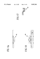
FIG. 15 is an enlarged detail of a female sonically weldable connector;
FIG. 16 is a view taken along lines 16--16 of FIG. 15;
FIG. 16a is a side view of the connector of FIG. 15;
FIG. 17 is a sectional view taken along lines 17--17 of FIG. 15;
FIG. 18 is a bottom plan view of the connector of FIG. 15;
FIG. 19a is an enlarged detail of the male sonically weldable connector of FIG. 11;
FIG. 19b is another enlarged detail of the male sonically weldable connector of FIG. 11;
FIG. 20 is a top plan view of a bandolier of cable ties in accordance with one preferred embodiment of the present invention;
FIG. 20a is a side view of the bandolier of FIG. 20;
FIG. 21 is an end view of the bandolier of FIG. 20;
FIG. 22 is an enlarged detail taken from FIG. 21;
FIG. 23 is an enlarged detail taken from FIG. 21; and
FIG. 24 is an enlarged detail illustrating the cooperation of the intermitting structure provided on the shots of cable ties.
DETAILED DESCRIPTION OF THE INVENTION
As described herein, prior art bandoliers are typically formed in a continuous molding operation, i.e., a plurality of longitudinal aligned cable ties (a shot of ties) is molded in one molding operation. Thereafter, the shot of ties is moved externally of the mold and a second longitudinally successive shot of ties is molded. In order to maintain continuity between the individual shots of cable ties, the finished shot must be maintained in contact with the mold so that the next successive shot of cable ties will be connected thereto.
Rather than connecting one shot of cable ties to the next by continuous molding, the present invention contemplates manufacturing separate individual shots of cable ties which can be interconnected together subsequent to molding to form a continuous strip of cable ties of any desired length. In this regard, the present invention provides connection capability between the individual shots of cable ties which allows the mentioned post-molding interconnection thereof.
An individual shot 10 of cable ties 12 is shown in FIG. 1. Shot 10 includes a plurality of cable ties 12 (e.g., 10 cable ties). Of course, each individual shot can include any number of cable ties, such number being limited only by the size of the molding apparatus.
Each cable tie 12 generally includes an elongate strap body 14 having a tail 16 at one end and a head 18 at the other end. In use, the cable tie is placed around a bundle of cables and the tail 16 is inserted through the head 18. The head 18 may include an appropriate locking mechanism such as a barb or a pawl which cooperates with the tail for securing a strap of body 14 within the head about the bundle of cables.
Each individual shot of ties defines a leading cable tie 12a and a trailing cable tie 12b. In turn, leading cable tie 12a defines a leading edge 20, while trailing cable tie 12b defines a trailing edge 22. In the embodiment of FIG. 1, both the leading and trailing edges 20, 22 are provided with a portion of structure sized and configured to cooperate with a complementary portion of structure formed on the edge of a second shot of ties. More particularly, the leading edge of one shot of ties includes a portion of structure sized and configured to cooperate with a portion of structure located on a trailing edge of another shot of ties, thus allowing interconnection of the two shots of ties into one continuous strip. If each shot included ten individual ties 12 (as shown in FIG. 1), the combined shots would form a continuous strip of twenty ties. As mentioned, the individual shots can be of as many ties as is commercially practical, and any number of individual shots can be joined together thereby allowing the formation of a continuous strip (i.e., a bandolier) of cable ties of any desired length.
Leading edge 20 of leading cable tie 12a includes a male snap connector 24, while trailing edge 22 of trailing cable tie 12b includes a female snap connector 26. It will be appreciated that this arrangement of the mentioned male and female snap connectors on the leading and trailing edges of the shot, respectively, allows the leading edge of one shot to be connected to trailing edge of the a second shot.
As shown in FIG. 1, the individual cable ties of the shot are interconnected by a web 28 which is integrally formed with the cable ties during the molding process. A web is preferably formed between each set of adjacent ties. As mentioned, the leading and trailing edges are provided with mechanical structure to allow connection of the shot to a second shot of cable ties.
The mold is preferably configured to form apertures 30 in each of the webs during the injection molding process. Apertures 30 facilitate the process of cutting the web free of the cable tie. More particularly, in one preferred embodiment, a single blade simultaneously cuts legs 32, 33 of the web, while a second blade simultaneously cuts legs 34, 36 of the web. As shown, a smooth notch 38 is formed on both sides of legs 32, 33, 34, and 36. These notches, which are formed in the edges of the cable ties during the molding process, facilitate the cutting operation and eliminate the likelihood of creating burrs or nicks which can subsequently produce stress fractures.
As best shown in FIG. 2, each shot 10 of cable ties is preferably provided with at least one dummy connector 40. As shown, the overall thickness of dummy connector 40 is D1, which in one preferred embodiment is approximately 0.144 inches. The dummy connector is sized to correspond to the thickness of the connectors located on the leading and trailing edges of the shots once such connectors have been interfitted with an adjacent connector on a second shot of cable ties. The inclusion of dummy connector 40 facilitates the bundling of the final bandolier of cable ties by creating a uniform thickness at pre-determined spots along the length of the bundle.
Each web also includes a plurality of indexing bosses 42. The embodiment of FIG. 1 includes two such bosses on each web. As will be recognized by those skilled in the art, indexing bosses 42 are utilized by the dispensing mechanism to properly index and orient the cable ties in the automatic tool. As shown in FIG. 2, bosses 42, which extend from a single surface of the web, are preferably formed with a height which corresponds to one-half the thickness of dummy connector 40.
As shown in FIG. 1, web 28 is preferably positioned on the tail side of an axis Y, such axis extending perpendicular to strap body 14 and defining the center of length of the cable ties. Stated differently, web 28 is located closer to the tail end of the cable tie than to the head end of the cable tie. The location of web 28 at a position closer to the tail end of the cable tie ensures that the tails of the bandolier are maintained in proper alignment. It will be recognized that certain automatic cable tie tools utilize dispensers which feed the ties to the tool in a "tail-forward" fashion. Thus, in these dispensers it is typically of greater importance to maintain the tails of cable tie bandolier in a pre-determined alignment than the heads of such bandolier. It will be appreciated that once the tail end of a cable tie is directed towards the automatic tool, the head will naturally follow.
In an alternative embodiment, as shown in FIG. 1a, web 28' of shot 10' is positioned on the head side of an axis Y', such axis extending perpendicular to strap body 14' and defining the center of length of the cable ties. Stated differently, web 28' is located closer to the head end of the cable tie than to the tail end of the cable tie. In one additional embodiment, web 28' is located near or at the center of gravity of the tie. The location of web 28' at a position closer to the head end of the cable tie ensures that the heads of the bandolier are maintained in proper alignment during feeding of the ties into an associated dispenser and discourages the heads of adjacent ties from becoming tangled with one another during such operation. The embodiment shown in FIG. 1a is useful in dispensers wherein the alignment of the heads (and lack of tangling thereof) is of greater importance than alignment of the tail ends of the ties. The embodiment shown in FIG. 1a is particularly useful in the dispenser described and claimed in commonly-owned U.S. application Ser. No. 09/124,499 filed Jul. 29, 1998, which is incorporated herein by reference.
As mentioned, each shot of cable ties is preferably formed through an injection-molding operation. The size of the mold determines the number of individual cable ties in such shot. One preferred material contemplated by the present invention is nylon 6-6. It is further contemplated that for shots of a greater number of ties, more than a single dummy connector may be required. In one preferred embodiment, a dummy connector is located adjacent every fifth tie. Of course, the number of dummy connectors can be increased or decreased based on the specification and the requirements of the automatic tool.
Referring to FIGS. 3 to 10, the male and female connectors, i.e., male snap connector 24 and female snap connector 26, are shown in greater detail. These connectors are also formed with notches 30 about the legs thereof to facilitate the cutting of the connector from the cable tie. As shown, the male and female connectors are sized to cooperate with one another in a snap fit manner which results in substantially permanent connection therebetween.
Referring now to FIGS. 11 to 18, it is contemplated herein that the cooperating interfitting mechanical structure located on the leading and trailing edges of the cable ties may subsequently be exposed to an ultrasonic welding process following the interfitting of such structure. In this regard, a male sonically weldable connector 44 and a female sonically weldable connector 46 are utilized on the leading and trailing edges of the individual shots of cable ties. As will be appreciated by those skill in the art, ultrasonic welding is a process whereby ultrasonic energy is directed at a pre-determined location, i.e., the sonically weldable connectors, which results in the melting of at least a portion of the material of such connector whereby the male and female connectors are fused to one another. In this regard, the male sonically weldable connector is preferably provided with a plurality of external ribs 48 which function as the ultrasonic directors for concentrating ultrasonic energy applied to the connector (see FIGS. 19a to 19b).
Referring to FIGS. 20 to 20a, a shot 100 of plural cable ties 102 molded in accordance with an alternative embodiment of the present invention is shown. Shot 100 includes a plurality of longitudinally aligned cable ties 102. The cable ties are arranged in two rows of side-by-side cable ties with each row of cable ties being connected in a tail-to-tail fashion. Thus, the heads 104 of the cable ties are disposed at opposite ends of the shot 100. Such a shot of cable ties may be manufactured in large cavitational molds having multiple cavities.
The individual ties 102 of the shot 100 may be connected between the heads 104 by a web 106 of material. Each tail 108 is connected to the tail 108 of the opposed cable tie of the other row. An additional web of material 110 is formed between the end-to-end tails.
Rather than connecting one shot of cable ties 100 to the next by continuous molding, the present invention contemplates manufacturing separate individual shots of cable ties which can be interconnected together subsequent to molding to form a continuous strip of cable ties of any desirable length. In this regard, the present invention provides connection capability between the individual shots of cable ties.
Referring to FIG. 21, the heads of the two rows of cable ties are shown in end view. The individual cable tie heads 104 at each longitudinal end of the two rows include interconnection structure which allows the heads of the end cable ties of one shot to be connected to the heads of the end cable ties of the next subsequently formed shot. Several techniques for mechanically interconnecting the shots of cable ties may be employed.
In the present invention with additional reference to FIGS. 22 and 23, one technique is particularly described. Head 104a at the end of one row of cable ties may include a mechanical interfitting structure 112 (detail B). The end cable tie head 104b in longitudinal opposition thereto may include a mechanically complimentary interfitting structure 114 extending therefrom (detail A). Structures 112 and 114 extend from heads 104a and 104b in a manner similar to webs 106 extending between the other heads 104. It can be appreciated that structure 112 of one shot of cable ties may be mechanically interfitted with structure 114 of an adjacent shot of cable ties so as to continuously connect successive shots of cable ties.
The present invention contemplates employing ultrasonic welding techniques to secure one shot of cable ties to the next using interfitting structure 112 and 114. As shown in FIG. 24, one of the structures, for instance, structure 112 may include an extending director 116 which serves to concentrate the ultrasonic energy so as to securely ultrasonically weld structure 112 to structure 114.
While ultrasonic welding has been shown as the preferred method of continuously connecting shots of cable ties, other mechanical interfitting structures may be incorporated into the molded shot of cable ties. For instance, a structure such as interfitting snap members or the like may also be employed to mechanically couple one shot of cable ties to the next successive shot of cable ties. Any other mechanical connection technique may also be employed.
It may be apparent that connection of the shots occur at both ends of the shot, i.e. at the heads of each row of ties. Once a desired number of shots of cable ties are coupled together in longitudinally successive fashion, the continuous strip of cable ties may be rolled around a reel or the like (not shown). Cable tie reels of such construction have particular utility in automatic cable tie tools which are used to apply cable ties about a bundle of cables or like articles.
The present invention provides several advantages over other techniques used to form continuous strips of cable ties. The present invention allows use of larger cavitational tooling which reduces the cost of the product. Furthermore, the cycle times necessary to form a shot of cable ties can be reduced. Finally, if in the manufacture of one shot of cable ties a defective cable tie is formed, that shot of cable ties can be discarded and the next successive shot of cable ties can be connected to the strip. Thus, one defective tie will not result in the necessity to discard a larger continuously molded strip of cable ties. Such a technique reduces scrap and lowers the cost of the product while increasing the quality of the cable tie strip manufactured thereby.
The bandolier of FIGS. 20 to 20a solves many of the deficiencies of the prior art by arranging the cable ties in two longitudinally extending rows of side-by-side cable ties with the heads of one row being mutually interconnected by webs therebetween and the heads of the other row being mutually interconnected by webs therebetween. The tails of each cable tie of one row are connected to the tails of the adjacent cable tie of the other row.
With reference to FIGS. 20 and 20a, bandolier 100 includes webs 106 integrally formed between the heads 104. The webs are formed along with the molding process which forms the bandolier of a plurality of cable ties. The webs serve to space the heads apart from one another. The webs are formed of a thin plastic material which may be easily severed during the dispensing process. The webs leave minimal waste and can be discarded in an easy fashion. The webs between the heads allow the cable ties to extend in substantially side-by-side parallel fashion where the tails of the cable ties of each row are longitudinally spaced from one another. In order to maintain stability between the ties of one row and the ties of the other row, the tails of the ties of one row are interconnected to the tails of the ties of the adjacent row. The molding process of the present invention forms a web 110 between oppositely adjacent tails of the cable ties so that the ties of one row are webbed together to the ties of the adjacent row.
Several advantages are achieved with the bandolier of FIG. 20. First, when winding the bandolier of cable ties on a reel, both opposite ends of the bandolier have the same thickness, thus the wound bandolier has uniform bulk at both ends and may be easily inserted into a dispenser. Second, by interconnecting adjacent tails, the tails are maintained in protective position preventing damage thereto. Damage to the tails during shipment or use in the automatic cable tie tool will result in difficulties in attempting to automatically bind the cable tie about a bundle of cables in an automatic tool environment. Furthermore, as the ties of the bandolier are employed in a dual row configuration, the thickness of the reel of ties for a given amount of ties is reduced significantly. This allows for a more compact dispenser and also reduces the chances of entanglement of the individual cable ties on the reel.
It will be appreciated that the present invention has been described herein with reference to certain preferred or exemplary embodiments. The preferred or exemplary embodiments described herein may be modified, changed, added to or deviated from without departing from the intent, spirit and scope of the present invention, and it is intended that all such additions, modifications, amendment and/or deviations be included within the scope of the followings claims.

Claims (5)

What is claimed is:
1. A cable tie bandolier for use with an automatic cable tie tool, comprising:
a plurality of cable ties, each of said ties including a tail at one end, a head at the opposite end and a strap body extending therebetween, each of said cable ties defining a length extending in the direction of said strap body and have a center located on said strap body along said length;
a web positioned between and interconnecting adjacent ties, said web located proximate the center of each of said adjacent ties whereby both said heads and tails of adjacent ties are maintained in parallel alignment; and
wherein said web comprises the exclusive means for interconnecting said adjacent ties, said web being located closer to said head of said tie than to said tail of said tie whereby alignment of said ties is accomplished.
2. The bandolier according to claim 1, wherein said web comprises a one-piece member integrally formed with the ties adjacent thereto.
3. The bandolier according to claim 1, wherein at least a portion of material is removed from said web along at least one side thereof to facilitate cutting of said web from said bandolier during installation of said cable ties.
4. The bandolier according to claim 1, wherein the sides of said cable ties are provided with smooth notches proximate said web to facilitate cutting of said web from said ties without burrs.
5. The bandolier according to claim 1, wherein each of said ties has a center of gravity, said center of gravity being located closer to said head of said tie than to said tail of said tie, and wherein said web is positioned at a location proximate the center of gravity of each of said ties.
US09/182,135 1997-10-22 1998-10-29 Cable tie bandoliers for use with automatic tools Expired - Lifetime US5967316A (en)

Priority Applications (1)

Application Number Priority Date Filing Date Title
US09/182,135 US5967316A (en) 1997-10-22 1998-10-29 Cable tie bandoliers for use with automatic tools

Applications Claiming Priority (2)

Application Number Priority Date Filing Date Title
US08/955,938 US5934465A (en) 1996-10-22 1997-10-22 Cable tie bandoliers for use with automatic tools
US09/182,135 US5967316A (en) 1997-10-22 1998-10-29 Cable tie bandoliers for use with automatic tools

Related Parent Applications (1)

Application Number Title Priority Date Filing Date
US08/955,938 Continuation-In-Part US5934465A (en) 1996-10-22 1997-10-22 Cable tie bandoliers for use with automatic tools

Publications (1)

Publication Number Publication Date
US5967316A true US5967316A (en) 1999-10-19

Family

ID=25497570

Family Applications (1)

Application Number Title Priority Date Filing Date
US09/182,135 Expired - Lifetime US5967316A (en) 1997-10-22 1998-10-29 Cable tie bandoliers for use with automatic tools

Country Status (1)

Country Link
US (1) US5967316A (en)

Cited By (21)

* Cited by examiner, † Cited by third party
Publication number Priority date Publication date Assignee Title
US6343693B1 (en) * 2000-04-19 2002-02-05 Allen D. Finley Cable tie dispenser
EP1186550A3 (en) * 2000-08-30 2004-01-14 Kotec's Co. Ltd. Sealing implement
US6681931B2 (en) 2000-04-19 2004-01-27 Allen D. Finley Cable tie dispenser
US6758018B2 (en) 2002-02-01 2004-07-06 Stanley Fastening Systems, L.P. Power driven nails for sheathing having enlarged diameter heads for enhanced retention and method
US20040173483A1 (en) * 2002-02-01 2004-09-09 Stanley Fastening Systems, L.P. Pallet nail with enlarged head
WO2005009877A2 (en) * 2003-07-24 2005-02-03 King Electrical Contractors, Llc. Dispenser for tie wraps
US20050072700A1 (en) * 2002-02-01 2005-04-07 Stanley Fastening Systems, L.P. Pallet nail with enlarged head
US20050265807A1 (en) * 2004-06-01 2005-12-01 Bruins Roger C Process for forming elongated flexible strip of nailing caps
US20050268435A1 (en) * 2002-05-30 2005-12-08 Rabin Moughelbay Typing device
US20100025447A1 (en) * 2008-07-30 2010-02-04 Colin Smart Bandolier
US20120159903A1 (en) * 2010-12-23 2012-06-28 Avery Dennison Corporation Wide filament fastener
CN102773876A (en) * 2012-07-31 2012-11-14 福建省石狮市华联服装配件企业有限公司 Automatic cutting machine for glue rope
US20140186140A1 (en) * 2011-05-20 2014-07-03 Hilti Aktiengesellschaft Receiving element and fixing element magazine strip
US20150007467A1 (en) * 2012-02-27 2015-01-08 Y-Tex Corporation Ear tag assembly and method of manufacture
US9108779B1 (en) * 2013-12-06 2015-08-18 Jose Pando Wire tie device
USD742730S1 (en) 2014-07-21 2015-11-10 National Nail Corp. Set of fastener caps
US9261224B2 (en) * 2012-08-17 2016-02-16 David William Harris Garment hanger collection apparatus
US9789991B2 (en) 2013-08-28 2017-10-17 Avery Dennison Corporation Reactor plate assembly and brush anvil for use in conjunction therewith
WO2019136913A1 (en) * 2018-01-12 2019-07-18 许修义 Connected tie strap and locking device
IT201800004463A1 (en) * 2018-04-13 2019-10-13 COLLECTION DEVICE OF CABLE TIES
US20190353284A1 (en) * 2018-05-18 2019-11-21 Kyocera Document Solutions Inc. Bundling band

Citations (49)

* Cited by examiner, † Cited by third party
Publication number Priority date Publication date Assignee Title
US34891A (en) * 1862-04-08 Improvement in apparatus for economizing fuel
US2823789A (en) * 1952-05-06 1958-02-18 Gilman Engineering & Mfg Corp Parts feeder ribbon
US2964171A (en) * 1958-01-15 1960-12-13 Thomas & Betts Corp Strip connectors
US3085292A (en) * 1959-02-13 1963-04-16 Bemis Bros Bag Co Method of producing open mesh sheeting of thermoplastic resin
US3196196A (en) * 1962-03-12 1965-07-20 Scovill Manufacturing Co Process and apparatus for molding zipper fasteners
US3431548A (en) * 1964-02-27 1969-03-04 Amp Inc Covering for a connecting member
US3515778A (en) * 1967-03-02 1970-06-02 Du Pont Continuous molding of thermoplastic resin
US3694863A (en) * 1970-10-14 1972-10-03 Amp Inc Bundle tie device
US3733657A (en) * 1972-05-25 1973-05-22 Dennison Mfg Co Assembly of attachments and method of manipulating the same
US3741385A (en) * 1970-03-25 1973-06-26 Permclip Prod Corp Fastener device
US3977050A (en) * 1974-04-19 1976-08-31 Monarch Marking Systems, Inc. Fastener assembly
US3979799A (en) * 1974-05-08 1976-09-14 Dennison Manufacturing Company Interlocking attachment device
DE2512825A1 (en) * 1975-03-22 1976-09-30 Reich Maschf Gmbh Karl Automatic driver screw holding strip - has threaded sleeves accommodating shanks with connecting ribs thinner than shanks
US4039078A (en) * 1973-04-04 1977-08-02 Dennison Manufacturing Company Fastener attachment stock
US4079485A (en) * 1976-05-25 1978-03-21 Amp Incorporated Bundle tie
US4230757A (en) * 1978-06-21 1980-10-28 Eastman Kodak Company Sonically securing articles in plastic mounts
US4417656A (en) * 1980-09-11 1983-11-29 Toska Co., Ltd. Cluster type tag pin assembly
US4429437A (en) * 1976-08-12 1984-02-07 Dennison Manufacturing Company Assemblages of fasteners
US4456123A (en) * 1979-08-31 1984-06-26 Dennison Manufacturing Company Method and apparatus for dispensing fasteners
US4495972A (en) * 1980-02-27 1985-01-29 Bowthorpe-Hellermann Limited Automatic tie gun
US4501782A (en) * 1983-11-18 1985-02-26 Mac/Gil Ltd. Method for bonding webs employing ultrasonic energy
US4505780A (en) * 1983-05-27 1985-03-19 Linear Limited Joining weatherstrippings
US4534464A (en) * 1982-12-08 1985-08-13 Nypro Inc. Manufacture and use of closely spaced attachments
US4586609A (en) * 1984-01-21 1986-05-06 Ben Clements & Sons, Inc. Tag pin fastener assembly and method
US4632247A (en) * 1982-11-24 1986-12-30 Panduit Corp. Tool for the automatic installation of discrete cable ties provided on a continuous ribbon of cable ties
US4640320A (en) * 1983-09-20 1987-02-03 Bowthorpe-Hellermann Limited Automatic tie gun
US4654935A (en) * 1984-12-10 1987-04-07 Dennison Manufacturing Company Structure, use and manufacture of fasteners
US4712677A (en) * 1977-08-24 1987-12-15 Dennison Manufacturing Company Method and apparatus for dispensing fasteners
US4790225A (en) * 1982-11-24 1988-12-13 Panduit Corp. Dispenser of discrete cable ties provided on a continuous ribbon of cable ties
US4851964A (en) * 1987-04-21 1989-07-25 Terumo Kabushiki Kaisha Connecting mechanism for electronic circuit board blanks
US4865895A (en) * 1987-06-17 1989-09-12 Raychem Corporation Marker sleeve assembly
US4901854A (en) * 1988-09-29 1990-02-20 Dennison Manufacturing Company Loop connected attachments
US5038931A (en) * 1989-05-04 1991-08-13 Kunreuther Steven J Assembly of attachments and device for attaching same
US5042535A (en) * 1989-03-30 1991-08-27 Bowthorpe-Hellermann Limited Automatic tie gun
US5119528A (en) * 1990-02-22 1992-06-09 Yazaki Corporation Tying band cluster
US5163552A (en) * 1988-10-12 1992-11-17 Barracuda Technologies Ab Banded fastener devices for fastening plastic film to a new reinforcement
US5213400A (en) * 1989-08-11 1993-05-25 Twist-Ease, Inc. Twist-tie dispenser apparatus and method
US5233063A (en) * 1988-02-18 1993-08-03 G. D. Searle & Co. Metabolites of pentanedioic acid derivatives
EP0571666A1 (en) * 1992-05-27 1993-12-01 Takao Kakihashi Bundling strap and method for manufacturing the strap in a continuous assembly
US5303821A (en) * 1992-11-06 1994-04-19 Ayres Donald B Resilient clip assembly
US5339954A (en) * 1993-01-29 1994-08-23 Steven Kunreuther Clip of attachments
US5395197A (en) * 1994-02-25 1995-03-07 Cario; Antonio Nail with non-circular head
US5452796A (en) * 1992-10-15 1995-09-26 Ohuchi; Masatoshi Blind rivet-holding belt for feeding a blind rivet into a continous riveting machine
US5482420A (en) * 1994-11-10 1996-01-09 Illinois Tool Works Inc. Collated screw package formed with welded wires
US5511661A (en) * 1993-11-01 1996-04-30 Clix Products, Inc. Plastic paper clip and integral sheet-like packaging thereof
US5542323A (en) * 1994-04-28 1996-08-06 G. Lyle Habermehl Screw strip with overlapping washers, and method and apparatus for installation
US5586353A (en) * 1992-10-29 1996-12-24 Avery Dennison Corp. Plastic fastener for shoe-lasting applications
US5595220A (en) * 1995-01-18 1997-01-21 Panduit Corp. Portable cable tie installation tool
US5799375A (en) * 1995-05-17 1998-09-01 J.E. Co., Ltd. Fastener assembly

Patent Citations (50)

* Cited by examiner, † Cited by third party
Publication number Priority date Publication date Assignee Title
US34891A (en) * 1862-04-08 Improvement in apparatus for economizing fuel
US2823789A (en) * 1952-05-06 1958-02-18 Gilman Engineering & Mfg Corp Parts feeder ribbon
US2964171A (en) * 1958-01-15 1960-12-13 Thomas & Betts Corp Strip connectors
US3085292A (en) * 1959-02-13 1963-04-16 Bemis Bros Bag Co Method of producing open mesh sheeting of thermoplastic resin
US3196196A (en) * 1962-03-12 1965-07-20 Scovill Manufacturing Co Process and apparatus for molding zipper fasteners
US3431548A (en) * 1964-02-27 1969-03-04 Amp Inc Covering for a connecting member
US3515778A (en) * 1967-03-02 1970-06-02 Du Pont Continuous molding of thermoplastic resin
US3741385A (en) * 1970-03-25 1973-06-26 Permclip Prod Corp Fastener device
US3694863A (en) * 1970-10-14 1972-10-03 Amp Inc Bundle tie device
US3733657A (en) * 1972-05-25 1973-05-22 Dennison Mfg Co Assembly of attachments and method of manipulating the same
US4039078A (en) * 1973-04-04 1977-08-02 Dennison Manufacturing Company Fastener attachment stock
US3977050A (en) * 1974-04-19 1976-08-31 Monarch Marking Systems, Inc. Fastener assembly
US3979799A (en) * 1974-05-08 1976-09-14 Dennison Manufacturing Company Interlocking attachment device
DE2512825A1 (en) * 1975-03-22 1976-09-30 Reich Maschf Gmbh Karl Automatic driver screw holding strip - has threaded sleeves accommodating shanks with connecting ribs thinner than shanks
US4079485A (en) * 1976-05-25 1978-03-21 Amp Incorporated Bundle tie
US4429437A (en) * 1976-08-12 1984-02-07 Dennison Manufacturing Company Assemblages of fasteners
US4712677A (en) * 1977-08-24 1987-12-15 Dennison Manufacturing Company Method and apparatus for dispensing fasteners
US4230757A (en) * 1978-06-21 1980-10-28 Eastman Kodak Company Sonically securing articles in plastic mounts
US4456123A (en) * 1979-08-31 1984-06-26 Dennison Manufacturing Company Method and apparatus for dispensing fasteners
US4495972A (en) * 1980-02-27 1985-01-29 Bowthorpe-Hellermann Limited Automatic tie gun
US4640319A (en) * 1980-02-27 1987-02-03 Bowthorpe-Hellermann Limited Automatic tie gun
US4417656A (en) * 1980-09-11 1983-11-29 Toska Co., Ltd. Cluster type tag pin assembly
US4632247A (en) * 1982-11-24 1986-12-30 Panduit Corp. Tool for the automatic installation of discrete cable ties provided on a continuous ribbon of cable ties
US4790225A (en) * 1982-11-24 1988-12-13 Panduit Corp. Dispenser of discrete cable ties provided on a continuous ribbon of cable ties
US4534464A (en) * 1982-12-08 1985-08-13 Nypro Inc. Manufacture and use of closely spaced attachments
US4505780A (en) * 1983-05-27 1985-03-19 Linear Limited Joining weatherstrippings
US4640320A (en) * 1983-09-20 1987-02-03 Bowthorpe-Hellermann Limited Automatic tie gun
US4501782A (en) * 1983-11-18 1985-02-26 Mac/Gil Ltd. Method for bonding webs employing ultrasonic energy
US4586609A (en) * 1984-01-21 1986-05-06 Ben Clements & Sons, Inc. Tag pin fastener assembly and method
US4654935A (en) * 1984-12-10 1987-04-07 Dennison Manufacturing Company Structure, use and manufacture of fasteners
US4851964A (en) * 1987-04-21 1989-07-25 Terumo Kabushiki Kaisha Connecting mechanism for electronic circuit board blanks
US4865895A (en) * 1987-06-17 1989-09-12 Raychem Corporation Marker sleeve assembly
US5233063A (en) * 1988-02-18 1993-08-03 G. D. Searle & Co. Metabolites of pentanedioic acid derivatives
US4901854A (en) * 1988-09-29 1990-02-20 Dennison Manufacturing Company Loop connected attachments
US5163552A (en) * 1988-10-12 1992-11-17 Barracuda Technologies Ab Banded fastener devices for fastening plastic film to a new reinforcement
US5042535A (en) * 1989-03-30 1991-08-27 Bowthorpe-Hellermann Limited Automatic tie gun
US5038931A (en) * 1989-05-04 1991-08-13 Kunreuther Steven J Assembly of attachments and device for attaching same
US5213400A (en) * 1989-08-11 1993-05-25 Twist-Ease, Inc. Twist-tie dispenser apparatus and method
US5119528A (en) * 1990-02-22 1992-06-09 Yazaki Corporation Tying band cluster
EP0571666A1 (en) * 1992-05-27 1993-12-01 Takao Kakihashi Bundling strap and method for manufacturing the strap in a continuous assembly
US5452796A (en) * 1992-10-15 1995-09-26 Ohuchi; Masatoshi Blind rivet-holding belt for feeding a blind rivet into a continous riveting machine
US5586353A (en) * 1992-10-29 1996-12-24 Avery Dennison Corp. Plastic fastener for shoe-lasting applications
US5303821A (en) * 1992-11-06 1994-04-19 Ayres Donald B Resilient clip assembly
US5339954A (en) * 1993-01-29 1994-08-23 Steven Kunreuther Clip of attachments
US5511661A (en) * 1993-11-01 1996-04-30 Clix Products, Inc. Plastic paper clip and integral sheet-like packaging thereof
US5395197A (en) * 1994-02-25 1995-03-07 Cario; Antonio Nail with non-circular head
US5542323A (en) * 1994-04-28 1996-08-06 G. Lyle Habermehl Screw strip with overlapping washers, and method and apparatus for installation
US5482420A (en) * 1994-11-10 1996-01-09 Illinois Tool Works Inc. Collated screw package formed with welded wires
US5595220A (en) * 1995-01-18 1997-01-21 Panduit Corp. Portable cable tie installation tool
US5799375A (en) * 1995-05-17 1998-09-01 J.E. Co., Ltd. Fastener assembly

Cited By (34)

* Cited by examiner, † Cited by third party
Publication number Priority date Publication date Assignee Title
US6343693B1 (en) * 2000-04-19 2002-02-05 Allen D. Finley Cable tie dispenser
US6681931B2 (en) 2000-04-19 2004-01-27 Allen D. Finley Cable tie dispenser
EP1186550A3 (en) * 2000-08-30 2004-01-14 Kotec's Co. Ltd. Sealing implement
US7395925B2 (en) 2002-02-01 2008-07-08 Stanley Fastening Systems, L.P. Pallet nail with enlarged head
US20050072700A1 (en) * 2002-02-01 2005-04-07 Stanley Fastening Systems, L.P. Pallet nail with enlarged head
US6758018B2 (en) 2002-02-01 2004-07-06 Stanley Fastening Systems, L.P. Power driven nails for sheathing having enlarged diameter heads for enhanced retention and method
US20040173483A1 (en) * 2002-02-01 2004-09-09 Stanley Fastening Systems, L.P. Pallet nail with enlarged head
US20050268435A1 (en) * 2002-05-30 2005-12-08 Rabin Moughelbay Typing device
US7543359B2 (en) * 2002-05-30 2009-06-09 Kableflags Pty. Ltd. Tying device
WO2005009877A3 (en) * 2003-07-24 2005-10-13 King Electrical Contractors Ll Dispenser for tie wraps
US20050067428A1 (en) * 2003-07-24 2005-03-31 King Steven J. Dispenser for tie wraps
WO2005009877A2 (en) * 2003-07-24 2005-02-03 King Electrical Contractors, Llc. Dispenser for tie wraps
US20050265807A1 (en) * 2004-06-01 2005-12-01 Bruins Roger C Process for forming elongated flexible strip of nailing caps
US7207095B2 (en) * 2004-06-01 2007-04-24 National Nail Corporation Process for forming elongated flexible strip of nailing caps
US20100025447A1 (en) * 2008-07-30 2010-02-04 Colin Smart Bandolier
US20120159903A1 (en) * 2010-12-23 2012-06-28 Avery Dennison Corporation Wide filament fastener
US9792839B2 (en) * 2010-12-23 2017-10-17 Avery Dennison Corporation Wide filament fastener and stock
US9206826B2 (en) * 2011-05-20 2015-12-08 Hilti Aktiengesellschaft Receiving element and fixing element magazine strip
US20140186140A1 (en) * 2011-05-20 2014-07-03 Hilti Aktiengesellschaft Receiving element and fixing element magazine strip
US9265232B2 (en) * 2012-02-27 2016-02-23 Y-Tex Corporation Ear tag assembly and method of manufacture
US20150007467A1 (en) * 2012-02-27 2015-01-08 Y-Tex Corporation Ear tag assembly and method of manufacture
CN102773876B (en) * 2012-07-31 2014-11-26 福建省石狮市华联服装配件企业有限公司 Automatic cutting machine for glue rope
CN102773876A (en) * 2012-07-31 2012-11-14 福建省石狮市华联服装配件企业有限公司 Automatic cutting machine for glue rope
US9261224B2 (en) * 2012-08-17 2016-02-16 David William Harris Garment hanger collection apparatus
US9789991B2 (en) 2013-08-28 2017-10-17 Avery Dennison Corporation Reactor plate assembly and brush anvil for use in conjunction therewith
US9108779B1 (en) * 2013-12-06 2015-08-18 Jose Pando Wire tie device
USD742730S1 (en) 2014-07-21 2015-11-10 National Nail Corp. Set of fastener caps
WO2019136913A1 (en) * 2018-01-12 2019-07-18 许修义 Connected tie strap and locking device
US20200339329A1 (en) * 2018-01-12 2020-10-29 Shenzhen Swift Automation Technology Co., Ltd. Connected Tie Strap and Locking Device
US11753221B2 (en) * 2018-01-12 2023-09-12 Shenzhen Swift Automation Technology Co., Ltd. Connected tie strap and locking device
IT201800004463A1 (en) * 2018-04-13 2019-10-13 COLLECTION DEVICE OF CABLE TIES
WO2019198045A1 (en) * 2018-04-13 2019-10-17 Pellicioli Emilio Cable ties collecting device
US20190353284A1 (en) * 2018-05-18 2019-11-21 Kyocera Document Solutions Inc. Bundling band
US10598303B2 (en) * 2018-05-18 2020-03-24 Kyocera Document Solutions, Inc. Bundling band

Similar Documents

Publication Publication Date Title
US5967316A (en) Cable tie bandoliers for use with automatic tools
US6631559B2 (en) Process for producing a cable including a plurality of flat cables
US6622346B2 (en) Sheet material including a surface fastener
KR100623950B1 (en) Fastener straps
WO1987001015A1 (en) Manufacture and use of closely spaced attachments
JPS6024009B2 (en) Mounting piece assembly
US5934465A (en) Cable tie bandoliers for use with automatic tools
JPH0121963B2 (en)
CA1238881A (en) Fastener assembly
US20110143074A1 (en) Moulded tie strips
US6557726B2 (en) Arrangement of fastening elements for holding bundles retained by cable ties
AU724496B2 (en) Cable tie bandoliers for use with automatic tools
US6308386B1 (en) Fastener clip and method of making the same
JP3870090B2 (en) Locking piece assembly
GB2126186A (en) Crimp terminal holder strips
AU9234898A (en) Serially associated electrical connectors for feeding automated wiring machines
JPH0624135Y2 (en) Insulation sleeve band for electrical connector
EP1009602A1 (en) Filamentary fastener and method of making same using insert molding
KR200387139Y1 (en) Holder for cable tie
ES2274735B1 (en) COMMUNICATIONS CABLE AND METHOD FOR PREPARATION.

Legal Events

Date Code Title Description
AS Assignment

Owner name: THOMAS & BETTS INTERNATIONAL, INC., NEVADA

Free format text: ASSIGNMENT OF ASSIGNORS INTEREST;ASSIGNORS:ABBRUZZESE, SALVATORE J.;BORDWELL, MARK A.;WELLS, PETER M.;REEL/FRAME:009555/0820;SIGNING DATES FROM 19981002 TO 19981019

STCF Information on status: patent grant

Free format text: PATENTED CASE

FEPP Fee payment procedure

Free format text: PAYOR NUMBER ASSIGNED (ORIGINAL EVENT CODE: ASPN); ENTITY STATUS OF PATENT OWNER: LARGE ENTITY

Free format text: PAYER NUMBER DE-ASSIGNED (ORIGINAL EVENT CODE: RMPN); ENTITY STATUS OF PATENT OWNER: LARGE ENTITY

FPAY Fee payment

Year of fee payment: 4

FPAY Fee payment

Year of fee payment: 8

FPAY Fee payment

Year of fee payment: 12

AS Assignment

Owner name: THOMAS & BETTS INTERNATIONAL LLC, DELAWARE

Free format text: CHANGE OF NAME;ASSIGNOR:THOMAS & BETTS INTERNATIONAL, INC.;REEL/FRAME:032388/0428

Effective date: 20130321