EP3736076B1 - Procédé de soudage par points par résistance et procédé de production d'un joint soudé par points par résistance - Google Patents
Procédé de soudage par points par résistance et procédé de production d'un joint soudé par points par résistance Download PDFInfo
- Publication number
- EP3736076B1 EP3736076B1 EP19751640.4A EP19751640A EP3736076B1 EP 3736076 B1 EP3736076 B1 EP 3736076B1 EP 19751640 A EP19751640 A EP 19751640A EP 3736076 B1 EP3736076 B1 EP 3736076B1
- Authority
- EP
- European Patent Office
- Prior art keywords
- current application
- current
- sheet
- mass
- steel sheet
- Prior art date
- Legal status (The legal status is an assumption and is not a legal conclusion. Google has not performed a legal analysis and makes no representation as to the accuracy of the status listed.)
- Active
Links
- 238000000034 method Methods 0.000 title claims description 66
- 238000003466 welding Methods 0.000 title claims description 52
- 238000004519 manufacturing process Methods 0.000 title description 2
- 229910000831 Steel Inorganic materials 0.000 claims description 131
- 239000010959 steel Substances 0.000 claims description 131
- 238000001816 cooling Methods 0.000 claims description 49
- 238000005204 segregation Methods 0.000 claims description 48
- 238000010438 heat treatment Methods 0.000 claims description 47
- 238000005496 tempering Methods 0.000 claims description 43
- 230000009467 reduction Effects 0.000 claims description 31
- 239000000203 mixture Substances 0.000 claims description 14
- 239000012535 impurity Substances 0.000 claims description 8
- 238000003825 pressing Methods 0.000 claims description 8
- 230000000694 effects Effects 0.000 description 26
- 229910000734 martensite Inorganic materials 0.000 description 23
- 230000000052 comparative effect Effects 0.000 description 18
- 238000002844 melting Methods 0.000 description 11
- 230000008018 melting Effects 0.000 description 11
- 239000011247 coating layer Substances 0.000 description 10
- 239000010949 copper Substances 0.000 description 9
- 238000007711 solidification Methods 0.000 description 9
- 230000008023 solidification Effects 0.000 description 9
- 239000011651 chromium Substances 0.000 description 8
- 230000007423 decrease Effects 0.000 description 8
- 239000011701 zinc Substances 0.000 description 8
- 229910052725 zinc Inorganic materials 0.000 description 8
- HCHKCACWOHOZIP-UHFFFAOYSA-N Zinc Chemical compound [Zn] HCHKCACWOHOZIP-UHFFFAOYSA-N 0.000 description 7
- 238000003303 reheating Methods 0.000 description 7
- 229910001566 austenite Inorganic materials 0.000 description 6
- 230000008569 process Effects 0.000 description 6
- 238000010791 quenching Methods 0.000 description 6
- 230000000171 quenching effect Effects 0.000 description 6
- 238000009792 diffusion process Methods 0.000 description 5
- 238000011156 evaluation Methods 0.000 description 5
- 238000005728 strengthening Methods 0.000 description 5
- 230000009466 transformation Effects 0.000 description 5
- 239000000463 material Substances 0.000 description 4
- 230000002829 reductive effect Effects 0.000 description 4
- 229910052796 boron Inorganic materials 0.000 description 3
- 229910052802 copper Inorganic materials 0.000 description 3
- 230000006866 deterioration Effects 0.000 description 3
- 230000007246 mechanism Effects 0.000 description 3
- 229910052750 molybdenum Inorganic materials 0.000 description 3
- 229910052759 nickel Inorganic materials 0.000 description 3
- 229910052758 niobium Inorganic materials 0.000 description 3
- 229910052719 titanium Inorganic materials 0.000 description 3
- 229910052720 vanadium Inorganic materials 0.000 description 3
- 101001071145 Homo sapiens Polyhomeotic-like protein 1 Proteins 0.000 description 2
- 102100033222 Polyhomeotic-like protein 1 Human genes 0.000 description 2
- 108091006597 SLC15A4 Proteins 0.000 description 2
- 102100021484 Solute carrier family 15 member 4 Human genes 0.000 description 2
- 229910052782 aluminium Inorganic materials 0.000 description 2
- 229910052791 calcium Inorganic materials 0.000 description 2
- 229910052804 chromium Inorganic materials 0.000 description 2
- 230000003247 decreasing effect Effects 0.000 description 2
- 239000000155 melt Substances 0.000 description 2
- 238000001556 precipitation Methods 0.000 description 2
- 230000000717 retained effect Effects 0.000 description 2
- 239000007790 solid phase Substances 0.000 description 2
- 229910007570 Zn-Al Inorganic materials 0.000 description 1
- 229910007567 Zn-Ni Inorganic materials 0.000 description 1
- 229910007614 Zn—Ni Inorganic materials 0.000 description 1
- 230000002411 adverse Effects 0.000 description 1
- 230000015572 biosynthetic process Effects 0.000 description 1
- 230000037396 body weight Effects 0.000 description 1
- ZTXONRUJVYXVTJ-UHFFFAOYSA-N chromium copper Chemical compound [Cr][Cu][Cr] ZTXONRUJVYXVTJ-UHFFFAOYSA-N 0.000 description 1
- 239000012141 concentrate Substances 0.000 description 1
- 230000001747 exhibiting effect Effects 0.000 description 1
- 239000000446 fuel Substances 0.000 description 1
- 230000006872 improvement Effects 0.000 description 1
- 238000005304 joining Methods 0.000 description 1
- 239000010410 layer Substances 0.000 description 1
- 230000036961 partial effect Effects 0.000 description 1
- 239000012071 phase Substances 0.000 description 1
- 238000007670 refining Methods 0.000 description 1
- 229920006395 saturated elastomer Polymers 0.000 description 1
- 239000000126 substance Substances 0.000 description 1
- 150000003568 thioethers Chemical class 0.000 description 1
Images
Classifications
-
- B—PERFORMING OPERATIONS; TRANSPORTING
- B23—MACHINE TOOLS; METAL-WORKING NOT OTHERWISE PROVIDED FOR
- B23K—SOLDERING OR UNSOLDERING; WELDING; CLADDING OR PLATING BY SOLDERING OR WELDING; CUTTING BY APPLYING HEAT LOCALLY, e.g. FLAME CUTTING; WORKING BY LASER BEAM
- B23K11/00—Resistance welding; Severing by resistance heating
- B23K11/10—Spot welding; Stitch welding
- B23K11/11—Spot welding
- B23K11/115—Spot welding by means of two electrodes placed opposite one another on both sides of the welded parts
-
- B—PERFORMING OPERATIONS; TRANSPORTING
- B23—MACHINE TOOLS; METAL-WORKING NOT OTHERWISE PROVIDED FOR
- B23K—SOLDERING OR UNSOLDERING; WELDING; CLADDING OR PLATING BY SOLDERING OR WELDING; CUTTING BY APPLYING HEAT LOCALLY, e.g. FLAME CUTTING; WORKING BY LASER BEAM
- B23K11/00—Resistance welding; Severing by resistance heating
- B23K11/16—Resistance welding; Severing by resistance heating taking account of the properties of the material to be welded
-
- B—PERFORMING OPERATIONS; TRANSPORTING
- B23—MACHINE TOOLS; METAL-WORKING NOT OTHERWISE PROVIDED FOR
- B23K—SOLDERING OR UNSOLDERING; WELDING; CLADDING OR PLATING BY SOLDERING OR WELDING; CUTTING BY APPLYING HEAT LOCALLY, e.g. FLAME CUTTING; WORKING BY LASER BEAM
- B23K11/00—Resistance welding; Severing by resistance heating
- B23K11/24—Electric supply or control circuits therefor
-
- B—PERFORMING OPERATIONS; TRANSPORTING
- B23—MACHINE TOOLS; METAL-WORKING NOT OTHERWISE PROVIDED FOR
- B23K—SOLDERING OR UNSOLDERING; WELDING; CLADDING OR PLATING BY SOLDERING OR WELDING; CUTTING BY APPLYING HEAT LOCALLY, e.g. FLAME CUTTING; WORKING BY LASER BEAM
- B23K31/00—Processes relevant to this subclass, specially adapted for particular articles or purposes, but not covered by only one of the preceding main groups
-
- C—CHEMISTRY; METALLURGY
- C21—METALLURGY OF IRON
- C21D—MODIFYING THE PHYSICAL STRUCTURE OF FERROUS METALS; GENERAL DEVICES FOR HEAT TREATMENT OF FERROUS OR NON-FERROUS METALS OR ALLOYS; MAKING METAL MALLEABLE, e.g. BY DECARBURISATION OR TEMPERING
- C21D6/00—Heat treatment of ferrous alloys
- C21D6/004—Heat treatment of ferrous alloys containing Cr and Ni
-
- C—CHEMISTRY; METALLURGY
- C21—METALLURGY OF IRON
- C21D—MODIFYING THE PHYSICAL STRUCTURE OF FERROUS METALS; GENERAL DEVICES FOR HEAT TREATMENT OF FERROUS OR NON-FERROUS METALS OR ALLOYS; MAKING METAL MALLEABLE, e.g. BY DECARBURISATION OR TEMPERING
- C21D9/00—Heat treatment, e.g. annealing, hardening, quenching or tempering, adapted for particular articles; Furnaces therefor
- C21D9/50—Heat treatment, e.g. annealing, hardening, quenching or tempering, adapted for particular articles; Furnaces therefor for welded joints
-
- C—CHEMISTRY; METALLURGY
- C22—METALLURGY; FERROUS OR NON-FERROUS ALLOYS; TREATMENT OF ALLOYS OR NON-FERROUS METALS
- C22C—ALLOYS
- C22C38/00—Ferrous alloys, e.g. steel alloys
- C22C38/002—Ferrous alloys, e.g. steel alloys containing In, Mg, or other elements not provided for in one single group C22C38/001 - C22C38/60
-
- C—CHEMISTRY; METALLURGY
- C22—METALLURGY; FERROUS OR NON-FERROUS ALLOYS; TREATMENT OF ALLOYS OR NON-FERROUS METALS
- C22C—ALLOYS
- C22C38/00—Ferrous alloys, e.g. steel alloys
- C22C38/02—Ferrous alloys, e.g. steel alloys containing silicon
-
- C—CHEMISTRY; METALLURGY
- C22—METALLURGY; FERROUS OR NON-FERROUS ALLOYS; TREATMENT OF ALLOYS OR NON-FERROUS METALS
- C22C—ALLOYS
- C22C38/00—Ferrous alloys, e.g. steel alloys
- C22C38/04—Ferrous alloys, e.g. steel alloys containing manganese
-
- C—CHEMISTRY; METALLURGY
- C22—METALLURGY; FERROUS OR NON-FERROUS ALLOYS; TREATMENT OF ALLOYS OR NON-FERROUS METALS
- C22C—ALLOYS
- C22C38/00—Ferrous alloys, e.g. steel alloys
- C22C38/06—Ferrous alloys, e.g. steel alloys containing aluminium
-
- C—CHEMISTRY; METALLURGY
- C22—METALLURGY; FERROUS OR NON-FERROUS ALLOYS; TREATMENT OF ALLOYS OR NON-FERROUS METALS
- C22C—ALLOYS
- C22C38/00—Ferrous alloys, e.g. steel alloys
- C22C38/18—Ferrous alloys, e.g. steel alloys containing chromium
- C22C38/40—Ferrous alloys, e.g. steel alloys containing chromium with nickel
- C22C38/42—Ferrous alloys, e.g. steel alloys containing chromium with nickel with copper
-
- C—CHEMISTRY; METALLURGY
- C22—METALLURGY; FERROUS OR NON-FERROUS ALLOYS; TREATMENT OF ALLOYS OR NON-FERROUS METALS
- C22C—ALLOYS
- C22C38/00—Ferrous alloys, e.g. steel alloys
- C22C38/18—Ferrous alloys, e.g. steel alloys containing chromium
- C22C38/40—Ferrous alloys, e.g. steel alloys containing chromium with nickel
- C22C38/44—Ferrous alloys, e.g. steel alloys containing chromium with nickel with molybdenum or tungsten
-
- C—CHEMISTRY; METALLURGY
- C22—METALLURGY; FERROUS OR NON-FERROUS ALLOYS; TREATMENT OF ALLOYS OR NON-FERROUS METALS
- C22C—ALLOYS
- C22C38/00—Ferrous alloys, e.g. steel alloys
- C22C38/18—Ferrous alloys, e.g. steel alloys containing chromium
- C22C38/40—Ferrous alloys, e.g. steel alloys containing chromium with nickel
- C22C38/46—Ferrous alloys, e.g. steel alloys containing chromium with nickel with vanadium
-
- C—CHEMISTRY; METALLURGY
- C22—METALLURGY; FERROUS OR NON-FERROUS ALLOYS; TREATMENT OF ALLOYS OR NON-FERROUS METALS
- C22C—ALLOYS
- C22C38/00—Ferrous alloys, e.g. steel alloys
- C22C38/18—Ferrous alloys, e.g. steel alloys containing chromium
- C22C38/40—Ferrous alloys, e.g. steel alloys containing chromium with nickel
- C22C38/48—Ferrous alloys, e.g. steel alloys containing chromium with nickel with niobium or tantalum
-
- C—CHEMISTRY; METALLURGY
- C22—METALLURGY; FERROUS OR NON-FERROUS ALLOYS; TREATMENT OF ALLOYS OR NON-FERROUS METALS
- C22C—ALLOYS
- C22C38/00—Ferrous alloys, e.g. steel alloys
- C22C38/18—Ferrous alloys, e.g. steel alloys containing chromium
- C22C38/40—Ferrous alloys, e.g. steel alloys containing chromium with nickel
- C22C38/50—Ferrous alloys, e.g. steel alloys containing chromium with nickel with titanium or zirconium
-
- C—CHEMISTRY; METALLURGY
- C22—METALLURGY; FERROUS OR NON-FERROUS ALLOYS; TREATMENT OF ALLOYS OR NON-FERROUS METALS
- C22C—ALLOYS
- C22C38/00—Ferrous alloys, e.g. steel alloys
- C22C38/18—Ferrous alloys, e.g. steel alloys containing chromium
- C22C38/40—Ferrous alloys, e.g. steel alloys containing chromium with nickel
- C22C38/54—Ferrous alloys, e.g. steel alloys containing chromium with nickel with boron
-
- B—PERFORMING OPERATIONS; TRANSPORTING
- B23—MACHINE TOOLS; METAL-WORKING NOT OTHERWISE PROVIDED FOR
- B23K—SOLDERING OR UNSOLDERING; WELDING; CLADDING OR PLATING BY SOLDERING OR WELDING; CUTTING BY APPLYING HEAT LOCALLY, e.g. FLAME CUTTING; WORKING BY LASER BEAM
- B23K2101/00—Articles made by soldering, welding or cutting
- B23K2101/006—Vehicles
-
- B—PERFORMING OPERATIONS; TRANSPORTING
- B23—MACHINE TOOLS; METAL-WORKING NOT OTHERWISE PROVIDED FOR
- B23K—SOLDERING OR UNSOLDERING; WELDING; CLADDING OR PLATING BY SOLDERING OR WELDING; CUTTING BY APPLYING HEAT LOCALLY, e.g. FLAME CUTTING; WORKING BY LASER BEAM
- B23K2101/00—Articles made by soldering, welding or cutting
- B23K2101/18—Sheet panels
-
- B—PERFORMING OPERATIONS; TRANSPORTING
- B23—MACHINE TOOLS; METAL-WORKING NOT OTHERWISE PROVIDED FOR
- B23K—SOLDERING OR UNSOLDERING; WELDING; CLADDING OR PLATING BY SOLDERING OR WELDING; CUTTING BY APPLYING HEAT LOCALLY, e.g. FLAME CUTTING; WORKING BY LASER BEAM
- B23K2103/00—Materials to be soldered, welded or cut
- B23K2103/02—Iron or ferrous alloys
- B23K2103/04—Steel or steel alloys
Definitions
- the present invention relates to a method of resistance spot welding, and a method of producing a resistance spot welded joint, see claims 1 and 4, respectively.
- the joint strength of a spot weld zone of a welded joint is evaluated in terms of TSS (Tensile shear strength) which is tensile strength in the shear direction of the joint (tensile shear strength) and CTS (Cross tension strength) which is tensile strength in the peeling direction of the joint (cross tension strength).
- TSS Torsile shear strength
- CTS Cross tension strength
- the TSS of the spot weld zone tends to increase with the tensile strength of the base material.
- the CTS of the spot weld zone may decrease in some cases when the tensile strength of the base material is 780 N/mm 2 (780 MPa) or more.
- the fracture form changes from plug fracture which is ductile fracture occurring in the base material around the spot weld zone or in the HAZ to interfacial fracture or partial plug fracture which is brittle fracture occurring in the nugget.
- the reason for the decrease in CTS is considered to be occurrence of brittle fracture due to segregation of P and S in the nugget edge and hardening of the nugget edge after quenching.
- various studies have been made on a postheating method in which current application is performed again after main current application.
- Patent Literature 1 and Patent Literature 2 each disclose a technique in which current application is performed for a short time as postheating.
- Patent Literature 1 describes a method in which postheating is performed under conditions satisfying formulae: 0.70 ⁇ WC ⁇ PC1 ⁇ 0.90 ⁇ WC and 40 ⁇ Pt1 ⁇ 80 (where WC is the welding current (kA), PC1 is the post-welding postheating current (kA), and Pt1 is the post-welding postheating time (ms))
- Patent Literature 2 describes a method in which postheating is performed under conditions satisfying formulae: 0.70 ⁇ WC ⁇ PHC1 ⁇ 0.90 ⁇ WC and 40 ⁇ PHT1 ⁇ 80 (where WC is the welding current (kA), PHC1 is the postheating current (kA), and PHT1 is the postheating time (ms)).
- Patent Literature 3 describes a technique in which cross tension strength is enhanced by a tempering method in which after forming a nugget, cooling is performed for a long time, and then, postheating is performed for a short time with a higher current than that for the initial current application.
- Patent Literature 4 describes a spot welding method of a high-strength steel sheet, the method including a first energization step, a cooling step, and a second energization step.
- Patent Literature 5 describes resistance spot welding of superposed steel sheets by main current application, preliminary current application prior to the main current application, and subsequent current application subsequent to the main current application, wherein a non-current application time for which current application is paused is provided between each current application.
- Patent Literature 1 or 2 when the technique of Patent Literature 1 or 2 is applied to a steel sheet containing, as a steel sheet component, Mn: 2.5 to 10.0% by mass (hereinafter, referred to as the "medium Mn steel sheet"), the following problems exist.
- Patent Literature 3 which is a method of performing postheating with a higher current than that for the initial current application, the tempering effect also cannot be obtained.
- a spot welding method including single current application only may be mentioned.
- this method when this method is applied to a high-strength steel sheet with a tensile strength of 780 MPa or more, a so-called quenched structure is produced by heating with single current application only, and the austenite structure undergoes martensitic transformation to a hard brittle martensite structure. As a result, a problem arises in that cross tension strength is decreased.
- the cross tension strength decreases.
- the reason for this is considered to be embrittlement of the nugget edge due to segregation during solidification and formation of a hardened structure by quenching.
- the present inventors have performed thorough studies on a method for improving the cross tension strength of such a high-strength steel sheet, i.e., each of a mechanism of the decrease in cross tension strength in resistance spot welding of a sheet combination including a high-strength steel sheet with a tensile strength of 780 MPa or more and a method for improving cross tension strength.
- the present invention has been made on the basis of the findings described above, and the gist of the invention is as follows.
- the joint strength of a resistance spot welded joint can be improved, thus providing a marked industrial effect.
- the above-described effect can be further improved.
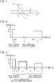
- Fig. 1 shows, as an example, a case where resistance spot welding is carried out on two steel sheets.
- a sheet combination 3 of overlapping steel sheets 1 and 2 is sandwiched between an electrode 4 disposed on the lower side of the sheet combination 3 and an electrode 5 disposed on the upper side of the sheet combination 3 (i.e., between a pair of upper and lower electrodes), and current is applied while applying pressure.
- a nugget 6 with a required size is formed to obtain a welded joint.
- Three or more steel sheets may be overlapped to form a sheet combination 3. In this case, a welded joint can be obtained in the same manner as that of the welding method described above.
- Suitable welding equipment for performing such a method of resistance spot welding may include a pair of upper and lower electrodes, in which pressure application and current application can be performed with the portion to be welded being interposed between the pair of electrodes, and may further include a pressing force control device and a welding current control device that can freely control the pressing force and the welding current during welding, respectively.
- the pressure application mechanism e.g., an air cylinder, servomotor, or the like
- the current control mechanism e.g., alternating current or direct current
- the type e.g., stationary or robotic gun
- the type of the power source single-phase alternating current, AC inverter, or DC inverter
- the shape of the electrodes is also not particularly limited.
- the electrode tip type is, for example, DR type (dome radius type), R type (radius type), or D type (dome type) described in JIS C 9304: 1999.
- the present invention can be applied to a method of welding a sheet combination of a plurality of sheets including a high-strength steel sheet.
- a method of welding a sheet combination of a plurality of sheets including a high-strength steel sheet For example, in the case of resistance spot welding shown in Fig. 1 , at least one of the steel sheet 1 and the steel sheet 2 in the sheet combination 3 is a high-strength steel sheet.
- a nugget tends to be hardened by quenching after spot welding.
- toughness of the nugget edge is improved. This produces an effect in that it is possible to reduce brittle fracture due to segregation in the nugget edge and hardening of the nugget edge after quenching in the resistance spot weld zone of a medium Mn high-strength steel sheet.
- At least one steel sheet in the sheet combination to be welded is set to be a high-strength steel sheet having a composition containing 0.08 ⁇ C ⁇ 0.3 (% by mass), 0.1 ⁇ Si ⁇ 0.8 (% by mass), 2.5 ⁇ Mn ⁇ 10.0 (% by mass), and P ⁇ 0.1 (% by mass), with the balance being Fe and unavoidable impurities.
- % in each component refers to "percent by mass”.
- the C content is an element that can form martensite and the like, thus contributing to strengthening of steel.
- the C content is less than 0.08%, the strength level decreases considerably. Accordingly, when the C content is less than 0.08%, it is very difficult to produce a steel sheet with a tensile strength of 780 MPa or more.
- the C content exceeds 0.3%, although the strength of the steel sheet increases, a nugget and its surrounding heat-affected zone are excessively hardened, and embrittlement proceeds. Consequently, it is difficult to improve cross tension strength. Therefore, the C content is set to be 0.08% or more and 0.3% or less.
- the C content is more preferably 0.10% or more and more preferably 0.2% or less.
- Si 0.1% or more and 0.8% or less
- the Si content When the Si content is 0.1% or more, this effectively acts on strengthening of steel. On the other hand, when the Si content exceeds 0.8%, although steel is strengthened, ductility may be deteriorated due to embrittlement, and toughness may be adversely affected in some cases. Therefore, the Si content is set to be 0.1% or more and 0.8% or less. The Si content is more preferably 0.1% or more and more preferably 0.5% or less.
- Mn 2.5% or more and 10.0% or less
- the present invention can also be suitably used for a medium Mn steel sheet, and the present invention is preferably directed to a high-strength steel sheet with a Mn content of 2.5% or more.
- the reason for this is that when the Mn content is less than 2.5%, even without providing long-time cooling as in the present invention, high joint strength can be obtained.
- the Mn content exceeds 10.0%, embrittlement or fracture due to embrittlement in the weld zone markedly occurs, which makes it difficult to improve joint strength. Therefore, the Mn content is set to be 2.5% or more and 10.0% or less.
- the Mn content is more preferably 3.5% or more and more preferably 8.0% or less.
- the P content is an unavoidable impurity.
- the P content is set to be 0.1% or less. More preferably, the P content is 0.02% or less.
- one or two or more elements selected from the group consisting of Cu, Ni, Mo, Cr, Nb, V, Ti, B, Al, and Ca may be incorporated as optional components.
- Cu, Ni, and Mo are elements that can contribute to improving the strength of steel.
- Cu is effective in strengthening steel.
- an excessively high Cu content may cause occurrence of fracture.
- the Cu content is preferably set to be 3% or less, and more preferably 1% or less.
- the Cu content is preferably set to be 0.005% or more.
- Ni improves hardenability, but is expensive.
- the Ni content is preferably set to be 3% or less, and more preferably 1% or less.
- the Ni content is preferably set to be 0.005% or more.
- Mo improves hardenability, but is expensive. Furthermore, at a Mo content of 1.0% or more, the effect is saturated. For this reason, when Mo is incorporated, the Mo content is preferably set to be 1.0% or less, and more preferably 0.8% or less. Furthermore, from the viewpoint of improving hardenability and improving the balance between strength and ductility, when Mo is incorporated, the Mo content is preferably set to be 0.005% or more.
- Cr is an element that can improve hardenability.
- the Cr content is preferably set to be 1.0% or less, and more preferably 0.8% or less.
- the Cr content is preferably set to be 0.01% or more.
- Nb and V are elements that can strengthen steel by controlling the structure by means of precipitation strengthening.
- an excessively high Nb content may cause an increase in the amount of hard martensite, and there is a concern that an excessively high V content may cause deterioration in toughness.
- the Nb content is preferably set to be 0.2% or less, and more preferably 0.1% or less.
- the Nb content is preferably set to be 0.005% or more.
- the V content is preferably set to be 0.5% or less, and more preferably 0.2% or less.
- the V content is preferably set to be 0.003% or more.
- Ti and B are elements that can strengthen steel by improving hardenability.
- the Ti content is preferably set to be 0.2% or less, and more preferably 0.1% or less.
- the Ti content is preferably set to be 0.003% or more.
- an excessively high B content may saturate the effect.
- the B content is preferably set to be 0.005% or less, and more preferably 0.004% or less.
- the B content is preferably set to be 0.0001% or more.
- Al is an element that can control the structure by austenite grain refining.
- an excessively high Al content may cause deterioration in toughness. Therefore, when Al is incorporated, the Al content is preferably set to be 2% or less, and more preferably 0.1% or less. Furthermore, from the viewpoint of purifying steel by deoxidation, when Al is incorporated, the Al content is preferably set to be 0.01% or more.
- Ca is an element that can contribute to improving workability of steel. However, there is a concern that an excessively high Ca content may cause deterioration in toughness. Therefore, when Ca is incorporated, the Ca content is preferably set to be 0.010% or less, and more preferably 0.005% or less. Furthermore, from the viewpoint of improving effects of sulfides, when Ca is incorporated, the Ca content is preferably set to be 0.0005% or more.
- one or two or more elements selected from the group consisting of Cu, Ni, Mo, Cr, Nb, V, Ti, B, Al, and Ca can be added.
- the balance other than the components described above includes Fe and unavoidable impurities.
- the tensile strength of the high-strength steel sheet having the components described above is preferably 780 MPa or more.
- the tensile strength of the base material is 780 MPa or more
- CTS may be decreased.
- the present invention even in a high-strength steel sheet with a tensile strength of 780 MPa or more, since it is possible to prevent brittle fracture due to segregation of P and S in the nugget edge and hardening of the nugget edge after quenching, a decrease in CTS can be suppressed. Note that even in a high-strength steel sheet with a tensile strength of less than 780 MPa, the effects described above can be naturally obtained.
- the term "zinc-coated steel sheet” refers to a steel sheet having a coating layer composed mainly of zinc, and examples of the coating layer composed mainly of zinc include all known zinc coating layers.
- examples of the coating layer composed mainly of zinc include a hot-dip zinc coating layer and an electro-zinc coating layer, and also include an Al coating layer, a Zn-Al coating layer, a Zn-Ni layer, and the like.
- a plurality of steel sheets of the same kind may be overlapped, or a plurality of steel sheets of different kinds may be overlapped.
- the steel sheets have different thicknesses.
- a surface-treated steel sheet having a coating layer and a steel sheet without a coating layer may be overlapped to each other.
- the sheet thickness is preferably 0.4 mm to 2.2 mm.
- the present invention relates to a method of resistance spot welding, in which steel sheets are overlapped together, and a step of applying current to a sheet combination 3 (a steel sheet 1 and a steel sheet 2) by using an electrode 4 and an electrode 5, as shown in Fig. 1 , is controlled as follows.
- a main current application step is performed, in which current application is performed with a current I w (kA).
- a post-tempering heat treatment step is performed, in which after cooling is performed for a cooling time t ct (ms) shown in formula (1) below, current application is performed with a current I t (kA) shown in formula (2) below for a current application time tt (ms) shown in formula (3) below: 800 ⁇ t ct ⁇ formula (1), 0.5 ⁇ I w ⁇ I t ⁇ I w ⁇ formula (2), and 500 ⁇ t t ⁇ formula (3).
- the main current application step is a current application step in which the overlapping portions of the steel sheet 1 and the steel sheet 2 are melted to form a nugget 6.
- current application conditions and pressure application conditions for forming the nugget 6 in the main current application step are not particularly limited. Commonly used welding conditions can be employed.
- main current application is performed preferably under the current application conditions of 120 ms to 400 ms and preferably under the pressure application conditions of 2.0 kN to 4.0 kN.
- the post-tempering heat treatment step is a postheat treatment step in which the edge of the nugget 6 formed in the main current application step is tempered to improve toughness.
- it is important to control welding conditions in the post-tempering heat treatment step as follows.
- cooling is performed for a cooling time t ct (ms) shown in the above formula (1), and subsequently, tempering current application is performed with a current I t (kA) shown in the above formula (2) for a current application time tt (ms) shown in the above formula (3).
- the cooling time t ct (ms) is set to be 800 (ms) or more.
- the cooling time t ct (ms) is preferably 1,000 (ms) or more, and more preferably 1,200 (ms) or more.
- the cooling time t ct (ms) is preferably 20,000 (ms) or less.
- the cooling time t ct (ms) is preferably 10,000 (ms) or less.
- the cooling time t ct (ms) is 10,000 (ms) or less, a sufficient tempering effect can be obtained, and therefore, most of the austenite structure of the nugget edge can be transformed into the tempered martensite structure.
- the cooling time t ct is more preferably set to be 2,000 (ms) or less.
- the range of the current It (kA) is set to be 0.5 ⁇ I w (kA) or more and I w (kA) or less, and preferably 0.6 ⁇ I w (kA) or more and 0.99 ⁇ I w (kA) or less.
- the current application time tt (ms) for tempering current application is set to be 500 (ms) or more.
- the current application time tt (ms) is preferably 1,000 (ms) or more.
- the current application time tt (ms) is more preferably 1,500 (ms) or more.
- the current application time tt (ms) is still more preferably 1,800 (ms) or more.
- the current application time tt (ms) for tempering current application is desirably set to be 20,000 (ms) or less.
- productivity is hindered, which is undesirable.
- the current application time tt is more preferably 8,000 (ms) or less, and still more preferably 3,000 (ms) or less.
- Fig. 2 shows an example of a current application pattern in a method of resistance spot welding not covered by the present invention described above.
- the main current application step and the post-tempering heat treatment step are controlled in the current application pattern shown in Fig. 2 .
- the current for main current application in the main current application step is set at I w (kA), and the current application time for main current application is set at t w (ms). Furthermore, the cooling time in the post-tempering heat treatment step, which is postheating, is set at t ct (ms), and the current is set at I t (kA).
- the current I t (kA) is set to be less than the current I w (kA) for main current application, and the current application time is set at tt (ms).
- a sheet combination 3 (steel sheets 1 and 2) is sandwiched between a pair of electrodes 4 and 5, and by applying current in the current application pattern shown in Fig. 2 , a nugget 6 is formed at the boundary between the steel sheets 1 and 2.
- tempering current application is performed, at a temperature just below the A 1 point and for a long time of 500 (ms) or more, on the nugget 6 formed by main current application. Therefore, even in the case where the sheet combination 3 includes a high-strength steel sheet having the steel sheet composition described above, toughness can be improved by tempering the edge of the nugget 6.
- a post-segregation reduction heat treatment step can be further included, in which after cooling is performed for a cooling time t cp (ms) shown in formula (4) below, current application is performed with a current I p (kA) shown in formula (5) below for a current application time t p (ms) shown in formula (6) below: 10 ⁇ t cp ⁇ formula (4), 0.6 ⁇ I w ⁇ I p ⁇ 0.99 ⁇ I w ⁇ formula (5), and 400 ⁇ t p ⁇ formula (6).
- the post-segregation reduction heat treatment step is a postheat treatment step for reducing segregation in the nugget edge of the nugget 6 formed in the main current application step.
- welding conditions in the post-segregation reduction heat treatment step performed between the main current application step and the post-tempering heat treatment step are preferably controlled as follows.
- cooling is performed for a cooling time t cp (ms) shown in the above formula (4), and subsequently, current application is performed again with a current I p (kA) shown in the above formula (5) for a current application time t p (ms) shown in the above formula (6).
- the cooling time t cp (ms) in the post-segregation reduction heat treatment step is less than 10 (ms)
- the time may not be sufficient to complete solidification of the molten nugget 6 in some cases.
- the nugget maintains the molten state, and it is not possible to achieve reduction of segregation of impurities due to diffusion of solute atoms after solidification, which is the effect of the post-segregation reduction heat treatment step. Therefore, the cooling time t cp (ms) is preferably set to be 10 (ms) or more, more preferably 100 (ms) or more, and still more preferably 200 (ms) or more.
- the cooling time t cp (ms) is preferably set to be 750 (ms) or less.
- the cooling time t cp (ms) is more preferably 700 (ms) or less, and still more preferably 250 (ms) or less.
- the range of the current I p (kA) is preferably set to be 0.6 ⁇ I w (kA) or more and 0.99 ⁇ I w (kA) or less, and more preferably 0.8 ⁇ I w (kA) or more.
- the current I p (kA) is still more preferably 0.87 ⁇ I w (kA) or more, and even still more preferably 0.90 ⁇ I w (kA) or more.
- the current I p (kA) is more preferably 0.98 ⁇ I w (kA) or less.
- the current application time t p (ms) for segregation reduction current application in the post-segregation reduction heat treatment step is less than 400 (ms)
- the current application time t p (ms) is preferably set to be 400 (ms) or more, and more preferably 600 (ms) or more.
- the current application time t p (ms) for segregation reduction current application in the post-segregation reduction heat treatment step is not particularly limited, the current application time t p (ms) is preferably set to be 8,000 (ms) or less. When the current application time t p (ms) exceeds 8,000 (ms), the above-described effect is unlikely to be obtained, and productivity is hindered, thus being undesirable.
- the current application time t p is preferably 7,000 (ms) or less, and more preferably 2,000 (ms) or less.
- Fig. 3 shows an example of a current application pattern in the method of resistance spot welding according to the present invention which further includes the post-segregation reduction heat treatment step between the main current application step and the post-tempering heat treatment step.
- the main current application step, the post-segregation reduction heat treatment step, and the post-tempering heat treatment step are controlled in the current application pattern shown in Fig. 3 .
- the current for main current application in the main current application step is set at I w (kA), and the current application time for main current application is set at t w (ms).
- the cooling time in the post-segregation reduction heat treatment step is set at t cp (ms), and the current for segregation reduction current application is set at I p (kA).
- the current I p (kA) is set to be equal to or less than the current I w (kA) for main current application ⁇ 0.99, and the current application time for segregation reduction current application is set at t p (ms).
- the cooling time in the post-tempering heat treatment step, which is postheating is set at t ct (ms), and the current for postheating is set at I t (kA).
- the current I t (kA) is set to be equal to or less than the current I w (kA) for main current application, and the current application time for postheating is set at tt (ms).
- a sheet combination 3 (steel sheets 1 and 2) is sandwiched between a pair of electrodes 4 and 5, and by applying current in the current application pattern shown in Fig. 3 , a nugget 6 is formed at the boundary between the steel sheets 1 and 2.
- the relationship between the current I p (kA) and the current I t (kA) is preferably I p ⁇ I t .
- the segregation reduction current application I p reduces segregation in the nugget edge at a temperature just below the melting point.
- the current I t for current application in post-tempering heat treatment performs tempering by retaining the nugget edge at a temperature equal to or less than the A 1 point.
- the A 1 point is greatly lower than the melting point, and even if cooling is performed for the cooling time t ct , the relationship between the currents is usually I p ⁇ I t .
- the nugget 6 formed by main current application is cooled for a short time and then reheated to near the melting point. Therefore, solidification segregation can be reduced by diffusion in the solid-phase state just below the melting point, and segregation in the edge of the nugget 6 can be reduced. As a result of this, the CTS of the resulting welded joint can be improved.
- the present invention relates to a method of producing a resistance spot welded joint using the method of resistance spot welding described above.
- resistance spot welding is performed in which, for example, a sheet combination of two or more overlapping steel sheets is sandwiched between a pair of electrodes and current is applied under predetermined welding conditions while applying pressure, thereby forming a nugget with a required size to obtain a resistance spot welded joint.
- the steel sheets, welding conditions, and the like are the same as those described above.
- the nugget edge is tempered to improve toughness.
- the reheating step post-segregation reduction heat treatment step
- solidification segregation of the nugget edge is reduced, and CTS is improved. Therefore, even in the case where a medium Mn steel sheet having the steel sheet composition described above is included as a high-strength steel sheet in the sheet combination, joint strength can be further improved.
- the nugget obtained by the present invention has a composition containing 0.05 ⁇ C ⁇ 0.35 (% by mass), 0.1 ⁇ Si ⁇ 0.8 (% by mass), and 2.0 ⁇ Mn ⁇ 10 (% by mass).
- the composition of the nugget may be obtained by a method in which a nugget is cut out from a sample produced by the method described above, and chemical analysis is performed.
- the composition may be obtained using a cross-sectional photograph of a weld zone, and converting the steel sheet component contents of each of the steel sheets with the cross-sectional area ratio between the melt zones of the upper and lower steel sheets.
- sheet combinations 3 were formed.
- sheet combinations a and b are sheet combinations in which two medium Mn steel sheets of the same kind are overlapped.
- a sheet combination c is a sheet combination in which medium Mn steel sheets of different kinds are overlapped.
- Sheet combinations d and e are sheet combinations in which a medium Mn steel sheet and a high-strength steel sheet are overlapped.
- a sheet combination f is a sheet combination in which same high C steel sheets are overlapped.
- a sheet combination g is a sheet combination in which same high Mn steel sheets are overlapped.
- a sheet combination h is a sheet combination in which three medium Mn steel sheets of the same kind are overlapped.
- Sheet combinations i and j are sheet combinations in which medium Mn steel sheets containing the optional components described above are overlapped.
- the sheet combinations a to g, i, and j all have the same thickness.
- nuggets 6 with a required size were formed, and resistance spot welded joints were obtained.
- current application was performed under the conditions described below.
- the pressing force during current application was set to be constant, at 3.5 kN.
- a DR type electrode made of chromium copper with a tip diameter of 6 mm and a tip curvature radius of 40 mm was used as each of the lower electrode 4 and the upper electrode 5.
- the nugget was formed so as to have a diameter of 5.5 ⁇ t (mm) or less when the sheet thickness was set at t (mm) .
- CTS was evaluated by the method described below.
Landscapes
- Chemical & Material Sciences (AREA)
- Engineering & Computer Science (AREA)
- Mechanical Engineering (AREA)
- Materials Engineering (AREA)
- Metallurgy (AREA)
- Organic Chemistry (AREA)
- Physics & Mathematics (AREA)
- Thermal Sciences (AREA)
- Crystallography & Structural Chemistry (AREA)
- Resistance Welding (AREA)
- Heat Treatment Of Articles (AREA)
Claims (4)
- Procédé de soudage par points par résistance dans lequel une combinaison de tôles (3) de deux tôles d'acier se chevauchant (1, 2) ou plus est enserrée entre une paire d'électrodes (4, 5) et est jointe par application d'un courant tout en appliquant une pression, le procédé comprenant :une étape d'application de courant principale dans laquelle l'application de courant est effectuée avec un courant IW, kA ; etensuite, une étape de traitement thermique après trempe dans laquelle, après qu'un refroidissement soit effectué pendant un temps de refroidissement tct, ms, indiqué dans la formule [1] ci-dessous, une application de courant est effectuée avec un courant It, kA, indiqué dans la formule [2] ci-dessous pendant un temps d'application de courant tt, ms, indiqué dans la formule [3] ci-dessous,dans lequel au moins une tôle d'acier (1, 2) dans la combinaison de tôles (3) présente une composition contenant 0,08 ≤ C ≤ 0,3, % en masse, 0,1 ≤ Si ≤ 0,8, % en masse, 2,5 ≤ Mn ≤ 10,0, % en masse, et P ≤ 0,1, % en masse, le reste étant du Fe et des impuretés inévitables :


 le procédé étant caractérisé en ce qu'il comprend en outre, entre l'étape d'application de courant principale et l'étape de traitement thermique après trempe :
une étape de traitement thermique de réduction après ségrégation dans laquelle, après que le refroidissement soit effectué pendant un temps de refroidissement tcp, ms, indiqué dans la formule [4] ci-dessous, une application de courant est effectuée avec un courant Ip, kA, indiqué dans la formule [5] ci-dessous, pendant un temps d'application de courant tp, ms, indiqué dans la formule [6] ci-dessous :


- Procédé selon la revendication 1, dans lequel au moins une tôle d'acier dans la combinaison de tôles présente la composition contenant en outre : un ou deux choisis parmi Cu ≤ 3, % en masse, Ni ≤ 3, % en masse, Mo ≤ 1,0, % en masse, Cr ≤ 1,0, % en masse, Nb ≤ 0,2, % en masse, V ≤ 0,5, % en masse, Ti ≤ 0,2, % en masse, B ≤ 0,005, % en masse, Al ≤ 2, % en masse, Ca ≤ 0,010, % en masse.
- Procédé selon la revendication 1 ou 2, dans lequel au moins une tôle d'acier dans la combinaison de tôles présente une résistance à la traction de 780 MPa ou plus.
- Procédé de production d'un joint soudé par points par résistance en utilisant le procédé selon l'une quelconque des revendications 1 à 3.
Applications Claiming Priority (2)
| Application Number | Priority Date | Filing Date | Title |
|---|---|---|---|
| JP2018021591 | 2018-02-09 | ||
| PCT/JP2019/004069 WO2019156073A1 (fr) | 2018-02-09 | 2019-02-05 | Procédé de soudage par points par résistance et procédé de production d'un joint soudé par points par résistance |
Publications (3)
| Publication Number | Publication Date |
|---|---|
| EP3736076A1 EP3736076A1 (fr) | 2020-11-11 |
| EP3736076A4 EP3736076A4 (fr) | 2021-04-28 |
| EP3736076B1 true EP3736076B1 (fr) | 2022-08-24 |
Family
ID=67548882
Family Applications (1)
| Application Number | Title | Priority Date | Filing Date |
|---|---|---|---|
| EP19751640.4A Active EP3736076B1 (fr) | 2018-02-09 | 2019-02-05 | Procédé de soudage par points par résistance et procédé de production d'un joint soudé par points par résistance |
Country Status (7)
| Country | Link |
|---|---|
| US (1) | US11992892B2 (fr) |
| EP (1) | EP3736076B1 (fr) |
| JP (1) | JP6763483B2 (fr) |
| KR (1) | KR102306924B1 (fr) |
| CN (1) | CN111712348B (fr) |
| MX (1) | MX2020008293A (fr) |
| WO (1) | WO2019156073A1 (fr) |
Families Citing this family (3)
| Publication number | Priority date | Publication date | Assignee | Title |
|---|---|---|---|---|
| JP6958765B1 (ja) * | 2020-03-05 | 2021-11-02 | Jfeスチール株式会社 | 抵抗スポット溶接方法および抵抗スポット溶接継手の製造方法 |
| CN112548295B (zh) * | 2020-12-05 | 2022-11-29 | 钟丽慧 | 汽车铝合金电阻点焊方法 |
| CN114850644A (zh) * | 2022-05-06 | 2022-08-05 | 本钢板材股份有限公司 | 一种2000MPa级热成形钢板的电阻点焊方法 |
Family Cites Families (17)
| Publication number | Priority date | Publication date | Assignee | Title |
|---|---|---|---|---|
| JPH05333560A (ja) | 1992-05-28 | 1993-12-17 | Fujitsu Ltd | 感光性樹脂膜の現像方法 |
| JP5151615B2 (ja) | 2008-03-28 | 2013-02-27 | 新日鐵住金株式会社 | 高強度鋼板のスポット溶接方法 |
| JP5293227B2 (ja) | 2009-01-30 | 2013-09-18 | Jfeスチール株式会社 | 高強度薄鋼板の抵抗スポット溶接方法 |
| KR101388692B1 (ko) | 2009-08-31 | 2014-04-24 | 신닛테츠스미킨 카부시키카이샤 | 스폿 용접 조인트 및 스폿 용접 방법 |
| JP2011067853A (ja) | 2009-09-28 | 2011-04-07 | Nippon Steel Corp | 高強度鋼板のスポット溶接方法 |
| JP5333560B2 (ja) * | 2011-10-18 | 2013-11-06 | Jfeスチール株式会社 | 高張力鋼板の抵抗スポット溶接方法及び抵抗スポット溶接継手 |
| JP5267640B2 (ja) | 2011-11-25 | 2013-08-21 | Jfeスチール株式会社 | 抵抗スポット溶接継手の評価方法 |
| JP6313921B2 (ja) * | 2011-12-21 | 2018-04-18 | Jfeスチール株式会社 | 抵抗スポット溶接方法 |
| MY172299A (en) | 2013-04-17 | 2019-11-20 | Nippon Steel Corp | Spot welding method |
| KR20140125969A (ko) | 2013-04-19 | 2014-10-30 | 삼성전자주식회사 | 소음 제거를 위한 헤드셋 |
| US10265797B2 (en) | 2013-07-11 | 2019-04-23 | Nippon Steel & Sumitomo Metal Corporation | Resistance spot welding method |
| JP6256601B2 (ja) | 2014-05-07 | 2018-01-10 | 新日鐵住金株式会社 | スポット溶接方法 |
| JP6409470B2 (ja) | 2014-09-30 | 2018-10-24 | 新日鐵住金株式会社 | スポット溶接方法 |
| WO2017010071A1 (fr) | 2015-07-10 | 2017-01-19 | Jfeスチール株式会社 | Procédé de soudage par points par résistance |
| KR102010196B1 (ko) | 2015-07-10 | 2019-08-12 | 제이에프이 스틸 가부시키가이샤 | 저항 스폿 용접 방법 |
| JP6052480B1 (ja) * | 2015-07-10 | 2016-12-27 | Jfeスチール株式会社 | 抵抗スポット溶接方法 |
| KR102058305B1 (ko) * | 2015-12-16 | 2019-12-20 | 제이에프이 스틸 가부시키가이샤 | 저항 스폿 용접 방법 및 용접 부재의 제조 방법 |
-
2019
- 2019-02-05 KR KR1020207022595A patent/KR102306924B1/ko active IP Right Grant
- 2019-02-05 WO PCT/JP2019/004069 patent/WO2019156073A1/fr unknown
- 2019-02-05 JP JP2019526617A patent/JP6763483B2/ja active Active
- 2019-02-05 CN CN201980012419.XA patent/CN111712348B/zh active Active
- 2019-02-05 MX MX2020008293A patent/MX2020008293A/es unknown
- 2019-02-05 EP EP19751640.4A patent/EP3736076B1/fr active Active
- 2019-02-05 US US16/967,193 patent/US11992892B2/en active Active
Also Published As
| Publication number | Publication date |
|---|---|
| KR20200103825A (ko) | 2020-09-02 |
| JP6763483B2 (ja) | 2020-09-30 |
| MX2020008293A (es) | 2020-09-25 |
| CN111712348A (zh) | 2020-09-25 |
| EP3736076A4 (fr) | 2021-04-28 |
| KR102306924B1 (ko) | 2021-09-29 |
| US11992892B2 (en) | 2024-05-28 |
| WO2019156073A1 (fr) | 2019-08-15 |
| JPWO2019156073A1 (ja) | 2020-02-27 |
| US20210362266A1 (en) | 2021-11-25 |
| EP3736076A1 (fr) | 2020-11-11 |
| CN111712348B (zh) | 2022-04-15 |
Similar Documents
| Publication | Publication Date | Title |
|---|---|---|
| EP4116455A1 (fr) | Procédé de soudage par points par résistance et procédé de fabrication de joint soudé par points par résistance | |
| RU2633414C2 (ru) | Точечно-сварное соединение и способ точечной сварки | |
| EP3473740A1 (fr) | Élément d'automobile ayant une soudure par résistance | |
| EP3736076B1 (fr) | Procédé de soudage par points par résistance et procédé de production d'un joint soudé par points par résistance | |
| EP3028799A1 (fr) | Joint soudé à l'arc par points et procédé permettant de produire ce dernier | |
| JP5151615B2 (ja) | 高強度鋼板のスポット溶接方法 | |
| JP6879345B2 (ja) | 抵抗スポット溶接方法、抵抗スポット溶接継手の製造方法 | |
| WO2013161937A1 (fr) | Joint de soudage par points | |
| JP5429327B2 (ja) | 高強度鋼板のスポット溶接方法 | |
| JP7453600B2 (ja) | スポット溶接継手及びスポット溶接継手の製造方法 | |
| JP5549618B2 (ja) | 引張強度980MPa以上のスポット溶接用高強度鋼板 | |
| JP2021154390A (ja) | 抵抗スポット溶接方法及び継手の製造方法 | |
| WO2020105325A1 (fr) | Structure assemblée et procédé de fabrication de structure assemblée | |
| JP7473861B1 (ja) | 抵抗スポット溶接方法 | |
| WO2024111224A1 (fr) | Procédé de soudage par points par résistance | |
| JP7468825B1 (ja) | 抵抗スポット溶接継手の製造方法 | |
| EP3978178A1 (fr) | Unité de soudage par points par résistance et procédé de soudage par points par résistance, et joint soudé par points par résistance et procédé de fabrication d'un joint soudé par points par résistance | |
| WO2024127865A1 (fr) | Procédé de fabrication d'un joint de soudage par points par résistance | |
| JP5429326B2 (ja) | 高強度鋼板のスポット溶接方法 | |
| JP2024087512A (ja) | スポット溶接方法および溶接継手の製造方法 | |
| JPS63310939A (ja) | スポット溶接性の良好な極低炭素鋼板 | |
| CN117897251A (zh) | 电阻点焊接头及其电阻点焊方法 | |
| JP3793294B2 (ja) | 耐亜鉛めっきわれ特性に優れた780MPa級高張力鋼の製造方法 |
Legal Events
| Date | Code | Title | Description |
|---|---|---|---|
| STAA | Information on the status of an ep patent application or granted ep patent |
Free format text: STATUS: THE INTERNATIONAL PUBLICATION HAS BEEN MADE |
|
| PUAI | Public reference made under article 153(3) epc to a published international application that has entered the european phase |
Free format text: ORIGINAL CODE: 0009012 |
|
| STAA | Information on the status of an ep patent application or granted ep patent |
Free format text: STATUS: REQUEST FOR EXAMINATION WAS MADE |
|
| 17P | Request for examination filed |
Effective date: 20200806 |
|
| AK | Designated contracting states |
Kind code of ref document: A1 Designated state(s): AL AT BE BG CH CY CZ DE DK EE ES FI FR GB GR HR HU IE IS IT LI LT LU LV MC MK MT NL NO PL PT RO RS SE SI SK SM TR |
|
| AX | Request for extension of the european patent |
Extension state: BA ME |
|
| A4 | Supplementary search report drawn up and despatched |
Effective date: 20210329 |
|
| RIC1 | Information provided on ipc code assigned before grant |
Ipc: B23K 11/11 20060101AFI20210323BHEP Ipc: B23K 11/16 20060101ALI20210323BHEP Ipc: B23K 11/24 20060101ALI20210323BHEP Ipc: B23K 101/00 20060101ALN20210323BHEP Ipc: B23K 101/18 20060101ALN20210323BHEP Ipc: B23K 103/04 20060101ALN20210323BHEP |
|
| DAV | Request for validation of the european patent (deleted) | ||
| DAX | Request for extension of the european patent (deleted) | ||
| RIC1 | Information provided on ipc code assigned before grant |
Ipc: B23K 103/04 20060101ALN20211027BHEP Ipc: B23K 101/18 20060101ALN20211027BHEP Ipc: B23K 101/00 20060101ALN20211027BHEP Ipc: B23K 11/24 20060101ALI20211027BHEP Ipc: B23K 11/16 20060101ALI20211027BHEP Ipc: B23K 11/11 20060101AFI20211027BHEP |
|
| GRAP | Despatch of communication of intention to grant a patent |
Free format text: ORIGINAL CODE: EPIDOSNIGR1 |
|
| STAA | Information on the status of an ep patent application or granted ep patent |
Free format text: STATUS: GRANT OF PATENT IS INTENDED |
|
| RIC1 | Information provided on ipc code assigned before grant |
Ipc: B23K 103/04 20060101ALN20211117BHEP Ipc: B23K 101/18 20060101ALN20211117BHEP Ipc: B23K 101/00 20060101ALN20211117BHEP Ipc: B23K 11/24 20060101ALI20211117BHEP Ipc: B23K 11/16 20060101ALI20211117BHEP Ipc: B23K 11/11 20060101AFI20211117BHEP |
|
| INTG | Intention to grant announced |
Effective date: 20211208 |
|
| GRAJ | Information related to disapproval of communication of intention to grant by the applicant or resumption of examination proceedings by the epo deleted |
Free format text: ORIGINAL CODE: EPIDOSDIGR1 |
|
| STAA | Information on the status of an ep patent application or granted ep patent |
Free format text: STATUS: REQUEST FOR EXAMINATION WAS MADE |
|
| GRAP | Despatch of communication of intention to grant a patent |
Free format text: ORIGINAL CODE: EPIDOSNIGR1 |
|
| STAA | Information on the status of an ep patent application or granted ep patent |
Free format text: STATUS: GRANT OF PATENT IS INTENDED |
|
| INTC | Intention to grant announced (deleted) | ||
| RIC1 | Information provided on ipc code assigned before grant |
Ipc: B23K 103/04 20060101ALN20220215BHEP Ipc: B23K 101/18 20060101ALN20220215BHEP Ipc: B23K 101/00 20060101ALN20220215BHEP Ipc: B23K 11/24 20060101ALI20220215BHEP Ipc: B23K 11/16 20060101ALI20220215BHEP Ipc: B23K 11/11 20060101AFI20220215BHEP |
|
| RIC1 | Information provided on ipc code assigned before grant |
Ipc: B23K 103/04 20060101ALN20220222BHEP Ipc: B23K 101/18 20060101ALN20220222BHEP Ipc: B23K 101/00 20060101ALN20220222BHEP Ipc: B23K 11/24 20060101ALI20220222BHEP Ipc: B23K 11/16 20060101ALI20220222BHEP Ipc: B23K 11/11 20060101AFI20220222BHEP |
|
| INTG | Intention to grant announced |
Effective date: 20220318 |
|
| GRAS | Grant fee paid |
Free format text: ORIGINAL CODE: EPIDOSNIGR3 |
|
| GRAA | (expected) grant |
Free format text: ORIGINAL CODE: 0009210 |
|
| STAA | Information on the status of an ep patent application or granted ep patent |
Free format text: STATUS: THE PATENT HAS BEEN GRANTED |
|
| AK | Designated contracting states |
Kind code of ref document: B1 Designated state(s): AL AT BE BG CH CY CZ DE DK EE ES FI FR GB GR HR HU IE IS IT LI LT LU LV MC MK MT NL NO PL PT RO RS SE SI SK SM TR |
|
| REG | Reference to a national code |
Ref country code: CH Ref legal event code: EP |
|
| REG | Reference to a national code |
Ref country code: DE Ref legal event code: R096 Ref document number: 602019018699 Country of ref document: DE |
|
| REG | Reference to a national code |
Ref country code: IE Ref legal event code: FG4D |
|
| REG | Reference to a national code |
Ref country code: AT Ref legal event code: REF Ref document number: 1513306 Country of ref document: AT Kind code of ref document: T Effective date: 20220915 |
|
| REG | Reference to a national code |
Ref country code: LT Ref legal event code: MG9D |
|
| REG | Reference to a national code |
Ref country code: NL Ref legal event code: MP Effective date: 20220824 |
|
| PG25 | Lapsed in a contracting state [announced via postgrant information from national office to epo] |
Ref country code: SE Free format text: LAPSE BECAUSE OF FAILURE TO SUBMIT A TRANSLATION OF THE DESCRIPTION OR TO PAY THE FEE WITHIN THE PRESCRIBED TIME-LIMIT Effective date: 20220824 Ref country code: RS Free format text: LAPSE BECAUSE OF FAILURE TO SUBMIT A TRANSLATION OF THE DESCRIPTION OR TO PAY THE FEE WITHIN THE PRESCRIBED TIME-LIMIT Effective date: 20220824 Ref country code: PT Free format text: LAPSE BECAUSE OF FAILURE TO SUBMIT A TRANSLATION OF THE DESCRIPTION OR TO PAY THE FEE WITHIN THE PRESCRIBED TIME-LIMIT Effective date: 20221226 Ref country code: NO Free format text: LAPSE BECAUSE OF FAILURE TO SUBMIT A TRANSLATION OF THE DESCRIPTION OR TO PAY THE FEE WITHIN THE PRESCRIBED TIME-LIMIT Effective date: 20221124 Ref country code: NL Free format text: LAPSE BECAUSE OF FAILURE TO SUBMIT A TRANSLATION OF THE DESCRIPTION OR TO PAY THE FEE WITHIN THE PRESCRIBED TIME-LIMIT Effective date: 20220824 Ref country code: LV Free format text: LAPSE BECAUSE OF FAILURE TO SUBMIT A TRANSLATION OF THE DESCRIPTION OR TO PAY THE FEE WITHIN THE PRESCRIBED TIME-LIMIT Effective date: 20220824 Ref country code: LT Free format text: LAPSE BECAUSE OF FAILURE TO SUBMIT A TRANSLATION OF THE DESCRIPTION OR TO PAY THE FEE WITHIN THE PRESCRIBED TIME-LIMIT Effective date: 20220824 Ref country code: FI Free format text: LAPSE BECAUSE OF FAILURE TO SUBMIT A TRANSLATION OF THE DESCRIPTION OR TO PAY THE FEE WITHIN THE PRESCRIBED TIME-LIMIT Effective date: 20220824 |
|
| REG | Reference to a national code |
Ref country code: AT Ref legal event code: MK05 Ref document number: 1513306 Country of ref document: AT Kind code of ref document: T Effective date: 20220824 |
|
| PG25 | Lapsed in a contracting state [announced via postgrant information from national office to epo] |
Ref country code: PL Free format text: LAPSE BECAUSE OF FAILURE TO SUBMIT A TRANSLATION OF THE DESCRIPTION OR TO PAY THE FEE WITHIN THE PRESCRIBED TIME-LIMIT Effective date: 20220824 Ref country code: IS Free format text: LAPSE BECAUSE OF FAILURE TO SUBMIT A TRANSLATION OF THE DESCRIPTION OR TO PAY THE FEE WITHIN THE PRESCRIBED TIME-LIMIT Effective date: 20221224 Ref country code: HR Free format text: LAPSE BECAUSE OF FAILURE TO SUBMIT A TRANSLATION OF THE DESCRIPTION OR TO PAY THE FEE WITHIN THE PRESCRIBED TIME-LIMIT Effective date: 20220824 Ref country code: GR Free format text: LAPSE BECAUSE OF FAILURE TO SUBMIT A TRANSLATION OF THE DESCRIPTION OR TO PAY THE FEE WITHIN THE PRESCRIBED TIME-LIMIT Effective date: 20221125 |
|
| PG25 | Lapsed in a contracting state [announced via postgrant information from national office to epo] |
Ref country code: SM Free format text: LAPSE BECAUSE OF FAILURE TO SUBMIT A TRANSLATION OF THE DESCRIPTION OR TO PAY THE FEE WITHIN THE PRESCRIBED TIME-LIMIT Effective date: 20220824 Ref country code: RO Free format text: LAPSE BECAUSE OF FAILURE TO SUBMIT A TRANSLATION OF THE DESCRIPTION OR TO PAY THE FEE WITHIN THE PRESCRIBED TIME-LIMIT Effective date: 20220824 Ref country code: ES Free format text: LAPSE BECAUSE OF FAILURE TO SUBMIT A TRANSLATION OF THE DESCRIPTION OR TO PAY THE FEE WITHIN THE PRESCRIBED TIME-LIMIT Effective date: 20220824 Ref country code: DK Free format text: LAPSE BECAUSE OF FAILURE TO SUBMIT A TRANSLATION OF THE DESCRIPTION OR TO PAY THE FEE WITHIN THE PRESCRIBED TIME-LIMIT Effective date: 20220824 Ref country code: CZ Free format text: LAPSE BECAUSE OF FAILURE TO SUBMIT A TRANSLATION OF THE DESCRIPTION OR TO PAY THE FEE WITHIN THE PRESCRIBED TIME-LIMIT Effective date: 20220824 Ref country code: AT Free format text: LAPSE BECAUSE OF FAILURE TO SUBMIT A TRANSLATION OF THE DESCRIPTION OR TO PAY THE FEE WITHIN THE PRESCRIBED TIME-LIMIT Effective date: 20220824 |
|
| REG | Reference to a national code |
Ref country code: DE Ref legal event code: R097 Ref document number: 602019018699 Country of ref document: DE |
|
| PG25 | Lapsed in a contracting state [announced via postgrant information from national office to epo] |
Ref country code: SK Free format text: LAPSE BECAUSE OF FAILURE TO SUBMIT A TRANSLATION OF THE DESCRIPTION OR TO PAY THE FEE WITHIN THE PRESCRIBED TIME-LIMIT Effective date: 20220824 Ref country code: EE Free format text: LAPSE BECAUSE OF FAILURE TO SUBMIT A TRANSLATION OF THE DESCRIPTION OR TO PAY THE FEE WITHIN THE PRESCRIBED TIME-LIMIT Effective date: 20220824 |
|
| PG25 | Lapsed in a contracting state [announced via postgrant information from national office to epo] |
Ref country code: AL Free format text: LAPSE BECAUSE OF FAILURE TO SUBMIT A TRANSLATION OF THE DESCRIPTION OR TO PAY THE FEE WITHIN THE PRESCRIBED TIME-LIMIT Effective date: 20220824 |
|
| PLBE | No opposition filed within time limit |
Free format text: ORIGINAL CODE: 0009261 |
|
| STAA | Information on the status of an ep patent application or granted ep patent |
Free format text: STATUS: NO OPPOSITION FILED WITHIN TIME LIMIT |
|
| 26N | No opposition filed |
Effective date: 20230525 |
|
| PG25 | Lapsed in a contracting state [announced via postgrant information from national office to epo] |
Ref country code: SI Free format text: LAPSE BECAUSE OF FAILURE TO SUBMIT A TRANSLATION OF THE DESCRIPTION OR TO PAY THE FEE WITHIN THE PRESCRIBED TIME-LIMIT Effective date: 20220824 |
|
| PG25 | Lapsed in a contracting state [announced via postgrant information from national office to epo] |
Ref country code: MC Free format text: LAPSE BECAUSE OF FAILURE TO SUBMIT A TRANSLATION OF THE DESCRIPTION OR TO PAY THE FEE WITHIN THE PRESCRIBED TIME-LIMIT Effective date: 20220824 |
|
| REG | Reference to a national code |
Ref country code: CH Ref legal event code: PL |
|
| REG | Reference to a national code |
Ref country code: BE Ref legal event code: MM Effective date: 20230228 |
|
| GBPC | Gb: european patent ceased through non-payment of renewal fee |
Effective date: 20230205 |
|
| PG25 | Lapsed in a contracting state [announced via postgrant information from national office to epo] |
Ref country code: LU Free format text: LAPSE BECAUSE OF NON-PAYMENT OF DUE FEES Effective date: 20230205 Ref country code: LI Free format text: LAPSE BECAUSE OF NON-PAYMENT OF DUE FEES Effective date: 20230228 Ref country code: CH Free format text: LAPSE BECAUSE OF NON-PAYMENT OF DUE FEES Effective date: 20230228 |
|
| REG | Reference to a national code |
Ref country code: IE Ref legal event code: MM4A |
|
| PG25 | Lapsed in a contracting state [announced via postgrant information from national office to epo] |
Ref country code: GB Free format text: LAPSE BECAUSE OF NON-PAYMENT OF DUE FEES Effective date: 20230205 |
|
| PG25 | Lapsed in a contracting state [announced via postgrant information from national office to epo] |
Ref country code: IE Free format text: LAPSE BECAUSE OF NON-PAYMENT OF DUE FEES Effective date: 20230205 Ref country code: GB Free format text: LAPSE BECAUSE OF NON-PAYMENT OF DUE FEES Effective date: 20230205 |
|
| PG25 | Lapsed in a contracting state [announced via postgrant information from national office to epo] |
Ref country code: BE Free format text: LAPSE BECAUSE OF NON-PAYMENT OF DUE FEES Effective date: 20230228 |
|
| PGFP | Annual fee paid to national office [announced via postgrant information from national office to epo] |
Ref country code: DE Payment date: 20231228 Year of fee payment: 6 |
|
| PG25 | Lapsed in a contracting state [announced via postgrant information from national office to epo] |
Ref country code: IT Free format text: LAPSE BECAUSE OF FAILURE TO SUBMIT A TRANSLATION OF THE DESCRIPTION OR TO PAY THE FEE WITHIN THE PRESCRIBED TIME-LIMIT Effective date: 20220824 |
|
| PGFP | Annual fee paid to national office [announced via postgrant information from national office to epo] |
Ref country code: FR Payment date: 20240103 Year of fee payment: 6 |