EP3735317B1 - Mischsystem - Google Patents
Mischsystem Download PDFInfo
- Publication number
- EP3735317B1 EP3735317B1 EP19736143.9A EP19736143A EP3735317B1 EP 3735317 B1 EP3735317 B1 EP 3735317B1 EP 19736143 A EP19736143 A EP 19736143A EP 3735317 B1 EP3735317 B1 EP 3735317B1
- Authority
- EP
- European Patent Office
- Prior art keywords
- mixing
- fluid
- mixing member
- piping
- curved surface
- Prior art date
- Legal status (The legal status is an assumption and is not a legal conclusion. Google has not performed a legal analysis and makes no representation as to the accuracy of the status listed.)
- Active
Links
Images


Classifications
-
- B—PERFORMING OPERATIONS; TRANSPORTING
- B01—PHYSICAL OR CHEMICAL PROCESSES OR APPARATUS IN GENERAL
- B01F—MIXING, e.g. DISSOLVING, EMULSIFYING OR DISPERSING
- B01F23/00—Mixing according to the phases to be mixed, e.g. dispersing or emulsifying
- B01F23/40—Mixing liquids with liquids; Emulsifying
- B01F23/45—Mixing liquids with liquids; Emulsifying using flow mixing
- B01F23/451—Mixing liquids with liquids; Emulsifying using flow mixing by injecting one liquid into another
-
- B—PERFORMING OPERATIONS; TRANSPORTING
- B01—PHYSICAL OR CHEMICAL PROCESSES OR APPARATUS IN GENERAL
- B01F—MIXING, e.g. DISSOLVING, EMULSIFYING OR DISPERSING
- B01F23/00—Mixing according to the phases to be mixed, e.g. dispersing or emulsifying
- B01F23/40—Mixing liquids with liquids; Emulsifying
- B01F23/47—Mixing liquids with liquids; Emulsifying involving high-viscosity liquids, e.g. asphalt
-
- B—PERFORMING OPERATIONS; TRANSPORTING
- B01—PHYSICAL OR CHEMICAL PROCESSES OR APPARATUS IN GENERAL
- B01F—MIXING, e.g. DISSOLVING, EMULSIFYING OR DISPERSING
- B01F25/00—Flow mixers; Mixers for falling materials, e.g. solid particles
- B01F25/30—Injector mixers
- B01F25/31—Injector mixers in conduits or tubes through which the main component flows
- B01F25/313—Injector mixers in conduits or tubes through which the main component flows wherein additional components are introduced in the centre of the conduit
- B01F25/3131—Injector mixers in conduits or tubes through which the main component flows wherein additional components are introduced in the centre of the conduit with additional mixing means other than injector mixers, e.g. screens, baffles or rotating elements
-
- B—PERFORMING OPERATIONS; TRANSPORTING
- B01—PHYSICAL OR CHEMICAL PROCESSES OR APPARATUS IN GENERAL
- B01F—MIXING, e.g. DISSOLVING, EMULSIFYING OR DISPERSING
- B01F25/00—Flow mixers; Mixers for falling materials, e.g. solid particles
- B01F25/30—Injector mixers
- B01F25/31—Injector mixers in conduits or tubes through which the main component flows
- B01F25/313—Injector mixers in conduits or tubes through which the main component flows wherein additional components are introduced in the centre of the conduit
- B01F25/3132—Injector mixers in conduits or tubes through which the main component flows wherein additional components are introduced in the centre of the conduit by using two or more injector devices
- B01F25/31322—Injector mixers in conduits or tubes through which the main component flows wherein additional components are introduced in the centre of the conduit by using two or more injector devices used simultaneously
-
- B—PERFORMING OPERATIONS; TRANSPORTING
- B01—PHYSICAL OR CHEMICAL PROCESSES OR APPARATUS IN GENERAL
- B01F—MIXING, e.g. DISSOLVING, EMULSIFYING OR DISPERSING
- B01F25/00—Flow mixers; Mixers for falling materials, e.g. solid particles
- B01F25/40—Static mixers
- B01F25/42—Static mixers in which the mixing is affected by moving the components jointly in changing directions, e.g. in tubes provided with baffles or obstructions
- B01F25/43—Mixing tubes, e.g. wherein the material is moved in a radial or partly reversed direction
- B01F25/431—Straight mixing tubes with baffles or obstructions that do not cause substantial pressure drop; Baffles therefor
- B01F25/4314—Straight mixing tubes with baffles or obstructions that do not cause substantial pressure drop; Baffles therefor with helical baffles
-
- B—PERFORMING OPERATIONS; TRANSPORTING
- B01—PHYSICAL OR CHEMICAL PROCESSES OR APPARATUS IN GENERAL
- B01F—MIXING, e.g. DISSOLVING, EMULSIFYING OR DISPERSING
- B01F27/00—Mixers with rotary stirring devices in fixed receptacles; Kneaders
- B01F27/05—Stirrers
- B01F27/11—Stirrers characterised by the configuration of the stirrers
- B01F27/112—Stirrers characterised by the configuration of the stirrers with arms, paddles, vanes or blades
- B01F27/1123—Stirrers characterised by the configuration of the stirrers with arms, paddles, vanes or blades sickle-shaped, i.e. curved in at least one direction
-
- B—PERFORMING OPERATIONS; TRANSPORTING
- B01—PHYSICAL OR CHEMICAL PROCESSES OR APPARATUS IN GENERAL
- B01F—MIXING, e.g. DISSOLVING, EMULSIFYING OR DISPERSING
- B01F35/00—Accessories for mixers; Auxiliary operations or auxiliary devices; Parts or details of general application
- B01F35/71—Feed mechanisms
- B01F35/717—Feed mechanisms characterised by the means for feeding the components to the mixer
- B01F35/7179—Feed mechanisms characterised by the means for feeding the components to the mixer using sprayers, nozzles or jets
-
- B—PERFORMING OPERATIONS; TRANSPORTING
- B01—PHYSICAL OR CHEMICAL PROCESSES OR APPARATUS IN GENERAL
- B01F—MIXING, e.g. DISSOLVING, EMULSIFYING OR DISPERSING
- B01F2215/00—Auxiliary or complementary information in relation with mixing
- B01F2215/04—Technical information in relation with mixing
- B01F2215/0413—Numerical information
- B01F2215/0418—Geometrical information
- B01F2215/0431—Numerical size values, e.g. diameter of a hole or conduit, area, volume, length, width, or ratios thereof
-
- B—PERFORMING OPERATIONS; TRANSPORTING
- B01—PHYSICAL OR CHEMICAL PROCESSES OR APPARATUS IN GENERAL
- B01F—MIXING, e.g. DISSOLVING, EMULSIFYING OR DISPERSING
- B01F23/00—Mixing according to the phases to be mixed, e.g. dispersing or emulsifying
- B01F23/40—Mixing liquids with liquids; Emulsifying
- B01F23/47—Mixing liquids with liquids; Emulsifying involving high-viscosity liquids, e.g. asphalt
- B01F23/471—Mixing liquids with liquids; Emulsifying involving high-viscosity liquids, e.g. asphalt using a very viscous liquid and a liquid of low viscosity
Definitions
- the present invention relates to a mixing system to more efficiently mix different types of fluids.
- a static mixer is a kind of mixing device continuously mixing a fluid which passes through a piping, without a moving part.
- the static mixer has excellent mixing efficiency, is free of noise and vibration because it does not have a moving part, and does not require maintenance. Therefore, a mixing system using the static mixer is used in various fields.
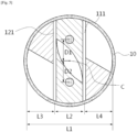
- FIG. 1 schematically illustrates a general static mixer. As illustrated in FIG. 1 , the static mixer is installed in a piping 10 to mix fluid introduced from one side of the piping 10. The fluid introduced from one side of the piping 10 is mixed, while passing through a right side mixing element 20 and a left side mixing element 30 which are arranged alternately.
- the right side mixing element 20 illustrated in FIG. 1 has a rear end rotated to be twisted by 180 degrees to the right as compared with a front end thereof
- the left side mixing element 30 has a rear end rotated to be twisted by 180 degrees to the left as compared with a front end thereof (the front end is an edge close to a side to which the fluid is introduced and the rear end is an edge away from the side to which the fluid is introduced).
- the rear end of the right side mixing element 20 is disposed at the rear and crisscrosses the front end of the left side mixing element 30 in contact therewith and the rear end of the left side mixing element 30 and the front end of the right side mixing element 20 disposed at the rear also crisscross each other. That is, the right and left side mixing elements are alternately installed so a flow direction of the fluid is reversed (rotational circulation) and flow of the fluid is changed (radical mixing), and accordingly, the fluid is easily mixed.
- WO2017/190759 A1 discloses a mixing system according to the preamble of claim 1.
- An object of the present invention is to provide a mixing system to improve mixing efficiency.
- a mixing system comprising: a piping which a first fluid is supplied; a mixing part including a plurality of mixing members installed in the piping, installed in a flow direction of the first fluid, having a plate-like shape in which a rear end thereof is twisted by a predetermined angle from a front end thereof, and disposed to be spaced apart from each other; and a supply part supplying a second fluid to a space between adjacent mixing members or a space between internal surface of the piping and each of the mixing members.
- each mixing member may be twisted at an angle of 45 to 180 degrees from the front end thereof.
- the first fluid may have viscosity 50 to 50000 times viscosity of the second fluid.
- the amount of the second fluid supplied to the piping may be 1 wt% or less of the first fluid.
- the mixing system may further include: a static mixer disposed at a rear end of the mixing part.
- the mixing system including an extensional mixing element according to the present invention has a plurality of exemplary embodiments according to exemplary embodiments of the added mixing element, and thus, the mixing system will be first described, and thereafter, exemplary embodiments of the extensional mixing element will be described.
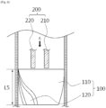
- FIG. 2 schematically illustrates a mixing system according to an exemplary embodiment of the present invention.
- a mixing system which is to mix a first fluid A and a second fluid B introduced into the piping 10, may include the piping 10, a mixing part 100 and a supply part 200 connected to the inside of the piping 10 from the outside, and may further include: a static mixer installed at a rear end of the mixing part 100.
- the first fluid A may be a relatively large amount of fluid having high viscosity and the second fluid B may be a relatively small amount of fluid having low viscosity.
- the second fluid when the first fluid A and the second fluid B are mixed, the second fluid may be less than 1% in a mass ratio with respect to a total mass of the mixed fluid as 100%, and viscosity of the first fluid A may be 50 to 50000 times that of the second fluid B.
- the static mixer is the same mixer as that described above in the Background Art. As illustrated in FIG. 2 , the right side mixing element 20 and the left side mixing element 30 are alternately arranged at the rear end of the mixing part 100 to mix the fluids introduced through the mixing part 100.
- the extensional mixing element which is a main feature of the present invention, may include the mixing part 100 and the supply part 200 and have various exemplary embodiments according to shapes or positions of the mixing part 100 and the supply part 200.
- the exemplary embodiments of the extensional mixing element of the present invention will be described in detail with reference to the accompanying drawings.
- FIG. 3 illustrates an extensional mixing element according to a first exemplary embodiment of the present invention.
- the extensional mixing element of the present invention is installed at a front end of the mixing system, and thus, FIG. 3 illustrates only a portion of an upper part of FIG. 2 .
- the mixing part 100 serves to mix the first fluid A and the second fluid B supplied to the inside of the piping, before the first fluid A and the second fluid B are mixed in the static mixer.
- the mixing part 100 may change flow of the first fluid A and the second fluid B supplied thereto, and may include a plurality of mixing members.
- the first mixing member 110 and the second mixing member 120 may have the same structure, may be installed inside the piping 10 and may be spaced apart from each other by a predetermined interval.
- the first mixing member 110 and the second mixing member 120 may be fixed to and installed in the inside of the piping 10 in various manners, and in an exemplary embodiment of the present invention, the first mixing member 110 and the second mixing member 120 may be fixed to the piping 10 by welding.
- the first mixing member 110 and the second mixing member 120 have a twisted plate-like shape and may be installed in a flow direction of the first fluid A supplied to the piping 10.
- an end of a portion to which the first fluid A is introduced will be referred to as a front end and an end of a portion from which the first fluid A is discharged will be referred to as a rear end.
- the first mixing member 110 includes a first outer side curved surface 113 and a first inner side curved surface 114 formed on both twisted side surfaces in which a first rear end 112 is rotated at a predetermined angle from a first front end 111 so as to be twisted.
- FIG. 4 illustrates the mixing part 100 and the supply part 200 of FIG. 3 viewed from the upper side to the lower side with respect to FIG. 3 .
- the first rear end 112 of the first mixing member 110 may be rotated to be twisted by a 60 degrees angle from the first front end 111.
- the second fluid B is supplied from the supply part 200 (to be described hereinafter) to the first inner side curved surface 114 formed as the first rear end 112 of the first mixing member 110 is rotated to be twisted by 60 degrees, relative to the first front end 111, and flow of the first fluid A and the second fluid B is changed through the first inner side curved surface 114, efficiency of mixing the two different fluids may be improved.
- the degree to which the first rear end 112 of the first mixing member 110 is rotated to be twisted at a predetermined angle from the first front end 111 is not limited to 60 degrees, and the first rear end 112 may be rotated to be twisted from the first front end 111 within a range of 45 to 180 degrees.
- the second rear end 122 of the second mixing member 120 may be rotated to be twisted by 60 degrees, relative to the second front end 121, and since the second rear end 122 of the second mixing member 120 may be rotated to be twisted by the predetermined angle, a second outer side curved surface 123 and a second inner side curved surface 124 are formed on both sides of the second mixing member 120.
- the first mixing member 110 and the second mixing member 120 may be fixed to the inner circumferential surface of the piping and spaced apart from each other by a predetermined distance, an internal mixing space 130 may be formed between the first mixing member 110 and the second mixing member 120.
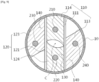
- FIG. 5 illustrates a distance between the first mixing member 110 and the second mixing member 120.
- a width of the internal mixing space 130 i.e., a distance L2 between the first front end 111 and the second front end with respect to FIG. 5 , may be 1/3 times an inner diameter L1 (diameter of the inner circumference) of the piping 110, and a distance L3 between the first front end 111 and the inner circumferential surface of the piping 10 and a distance L4 between the second front end 121 and the inner circumferential surface of the piping 10 may be 1/3 times the inner diameter L1 of the piping 10.
- the distance L2 is not limited to the 1/3 times the inner diameter of the piping 10 and may be 0.2 to 0.6 times.
- the distances L3 and L4 may each be a length obtained by subtracting the distance L2 from the distance L1.
- the supply part 200 supplies the second fluid B to the internal mixing space 130.
- the supply part 200 may supply the second fluid B to the internal mixing space 130 through a plurality of flow paths, and in order to realize the plurality of flow paths, the supply part 200 may include a first nozzle 210 and a second nozzle 220.
- the first nozzle 210 and the second nozzle 220 may supply the second fluid B by the same amount and at the same supply rate by stopping the piping 10 from the outside.
- the second fluid B supplied from the first nozzle 210 and the second fluid B supplied from the second nozzle 220 are mixed as flows thereof are changed along the first inner side curved surface 114 of the first mixing member 110 and the second inner side curved surface 124 of the second mixing member 120.
- the second fluids B supplied from the first nozzle 210 and the second nozzle 220 need to be supplied to the first inner side curved surface 114 and the second inner side curved surface 124, respectively.
- positions of the first nozzle 210 and the second nozzle 220 may overlap the areas of the first inner side curved surface 114 and the second inner side curved surface 124 respectively in FIG. 5 and may be symmetrical to each other with respect to the center C of the piping 10. That is, the distance D1 from the first nozzle 210 to the center C of the piping 10 and the distance D2 from the second nozzle 210 to the center C of the piping 10 may be equal to each other.
- the method of supplying, by the supply part 200, the second fluid in the two flow paths using the first nozzle 210 and the second nozzle 220 has been described, but the supply part 200 of the present invention is not limited thereto and the position and the number of the supply part 200 do not matter as long as the second fluid B is supplied to the internal mixing space 130 through the even number of flow paths and the supplied second fluid B is supplied to the inner side curved surfaces formed by the mixing members.
- the second fluid supplied from the supply part 200 through the flow path may be supplied to a space between each of the first mixing member 110 and the second mixing member 120 and the piping 10, that is to the first outer side curved surface 113 and the second outer side curved surface 123.
- FIG. 6 illustrates a side view of the extensional mixing element according to the first exemplary embodiment of the present invention.
- a length L5 of the mixing part 100 illustrated in FIG. 6 may be 0.8 times the inner diameter of the piping 10 but it not limited thereto and the length L5 of the mixing part 100 may be 0.4 to 1.2 times the inner diameter of the piping 10.
- positions of the ends of the first nozzle 210 and the second nozzle 220 are the same as positions of the front end of the mixing element or may be lower than the position of the front end of the mixing element in FIG. 5 (rear side with respect to the piping). This is to supply the second fluids supplied through the first and second nozzles 210 and 220 directly to the curved surface formed by the first mixing member 110 and the second mixing member 120, without being spread to other parts.
- the extensional mixing element according to the first exemplary embodiment of the present invention illustrated in FIGS. 3 to 6 is installed at the front end of the static mixer and used for the purpose of preliminary mixing, which obtains a high mixing effect within a relatively short interval, while less differential pressure is applied, when two different types of fluids having a significantly high difference in viscosity.
- FIG. 7 illustrates a cross-section of an extensional mixing element according to the second exemplary embodiment of the present invention.
Landscapes
- Chemical & Material Sciences (AREA)
- Chemical Kinetics & Catalysis (AREA)
- Engineering & Computer Science (AREA)
- Civil Engineering (AREA)
- Structural Engineering (AREA)
- Dispersion Chemistry (AREA)
- Accessories For Mixers (AREA)
Claims (12)
- Mischsystem, wobei das Mischsystem umfasst:eine Leitung (10) zum Zuführen eines ersten Fluids (A);ein in der Leitung (10) installiertes Mischteil (100) mit einem ersten Mischelement (110) und einem zweiten Mischelement (120), das in einer Strömungsrichtung des ersten Fluids (A) installiert ist, wobei das erste Mischelement (110) und das zweite Mischelement (120) jeweils eine verdrehte Plattenform aufweisen, wobei das erste Mischelement (110) eine erste äußere gekrümmte Seitenfläche (113) und eine erste innere gekrümmte Seitenfläche (114) umfasst, die auf beiden verdrehten Seitenflächen ausgebildet sind, wobei ein erstes hinteres Ende (112) in einem vorgegebenen Winkel von einem ersten vorderen Ende (111) gedreht ist, so dass es verdreht ist, wobei das zweite Mischelement (120) eine zweite äußere gekrümmte Seitenfläche (123) und eine zweite innere gekrümmte Seitenfläche (124) umfasst, die auf beiden verdrehten Seitenflächen ausgebildet sind, wobei ein zweites hinteres Ende (122) in einem vorgegebenen Winkel von einem zweiten vorderen Ende (121) gedreht ist, so dass es verdreht ist, und wobei das erste Mischelement (110) und das zweite Mischelement (120) an der Innenumfangsfläche der Leitung (10) fixiert und so angeordnet sind, dass sie voneinander beabstandet sind, um einen inneren Mischraum (130) zu bilden;wobei das vordere Ende jedes des ersten Mischelements (111) und des zweiten Mischelements (121) in einer Richtung angeordnet ist, in der das erste Fluid (A) zugeführt wird, und wobei das hintere Ende davon (112, 122) in einer Richtung angeordnet ist, in der das erste Fluid (A) abgelassen wird; und wobei auf jeder Seite ausgebildete innere gekrümmte Seitenflächen (114, 124) einander zugewandt angeordnet sind, gekennzeichnet durch ein Zuführteil (200) zum Zuführen eines zweiten Fluids (B) in den inneren Mischraum (130) oder den Raum zwischen einer Innenfläche der Leitung (10) und jedem des ersten Mischelements (110) und des zweiten Mischelements (120).
- Mischsystem nach Anspruch 1, wobei das hintere Ende jedes des ersten Mischelements (112) und des zweiten Mischelements (122) in einem Winkel von 45 bis 180 Grad vom vorderen Ende jedes des ersten Mischelements (111) und des zweiten Mischelements (121) verdreht ist.
- Mischsystem nach Anspruch 1, wobei eine Länge vom vorderen Ende (111) zum hinteren Ende (112) des ersten Mischelements (110) und die Länge vom vorderen Ende (121) zum hinteren Ende (122) des zweiten Mischelements (120) das 0,4- bis 1,2-Fache des Durchmessers der Leitung (10) betragen.
- Mischsystem nach Anspruch 1, wobei ein Abstand zwischen dem ersten Mischelement (110) und dem zweiten Mischelement (120) das 0,2- bis 0,6-Fache eines Durchmessers der Leitung (10) beträgt.
- Mischsystem nach Anspruch 1, wobei das Zuführteil (200) das zweite Fluid (B) durch eine Vielzahl von Strömungswegen zum Inneren der Leitung (10) zuführt.
- Mischsystem nach Anspruch 5, wobei das Zuführteil (200) das zweite Fluid (B) durch mindestens ein oder mehrere Paare von Strömungswegen zu einer gekrümmten Oberflächenform auf jeder Seite des ersten Mischelements (113, 114) und des zweiten Mischelements (123, 124) zuführt.
- Mischsystem nach Anspruch 1, wobei in Bezug auf die Länge der Leitung (10) eine Position eines Endes des Zuführteils (200), durch das das zweite Fluid (B) abgelassen wird, dieselbe ist wie eine Position des vorderen Endes des ersten Mischelements (111) und des zweiten Mischelements (121) oder das Ende des Zuführteils (200) auf einer Rückseite relativ zum vorderen Ende des ersten Mischelements (111) und des zweiten Mischelements (121) positioniert ist.
- Mischsystem nach Anspruch 1, wobei das erste Fluid (A) eine Viskosität aufweist, die höher als eine Viskosität des zweiten Fluids (B) ist.
- Mischsystem nach Anspruch 1, wobei das erste Fluid (A) eine Viskosität aufweist, die das 50- bis 50000-Fache einer Viskosität des zweiten Fluids (B) ist.
- Mischsystem nach Anspruch 1, wobei das erste Fluid (A) in einer größeren Menge als das zweite Fluid (B) zugeführt wird.
- Mischsystem nach Anspruch 10, wobei die der Leitung (10) zugeführte Menge des zweiten Fluids (B) 1 Gew.-% oder weniger des ersten Fluids (A) beträgt.
- Mischsystem nach Anspruch 1, ferner umfassend:
einen statischen Mischer, der an einem hinteren Ende des Mischteils (100) angeordnet ist.
Applications Claiming Priority (2)
| Application Number | Priority Date | Filing Date | Title |
|---|---|---|---|
| KR1020180001571A KR101922535B1 (ko) | 2018-01-05 | 2018-01-05 | 추가 혼합 유닛을 포함하는 혼합 시스템 |
| PCT/IB2019/050041 WO2019135187A1 (en) | 2018-01-05 | 2019-01-03 | Mixing system |
Publications (3)
| Publication Number | Publication Date |
|---|---|
| EP3735317A1 EP3735317A1 (de) | 2020-11-11 |
| EP3735317A4 EP3735317A4 (de) | 2021-10-13 |
| EP3735317B1 true EP3735317B1 (de) | 2024-12-04 |
Family
ID=64561633
Family Applications (1)
| Application Number | Title | Priority Date | Filing Date |
|---|---|---|---|
| EP19736143.9A Active EP3735317B1 (de) | 2018-01-05 | 2019-01-03 | Mischsystem |
Country Status (10)
| Country | Link |
|---|---|
| US (1) | US12296305B2 (de) |
| EP (1) | EP3735317B1 (de) |
| JP (1) | JP7369128B2 (de) |
| KR (1) | KR101922535B1 (de) |
| CN (1) | CN111655361A (de) |
| CA (1) | CA3085411A1 (de) |
| ES (1) | ES3009708T3 (de) |
| RU (1) | RU2766935C2 (de) |
| SA (1) | SA520412304B1 (de) |
| WO (1) | WO2019135187A1 (de) |
Families Citing this family (4)
| Publication number | Priority date | Publication date | Assignee | Title |
|---|---|---|---|---|
| CN114259895A (zh) * | 2021-10-14 | 2022-04-01 | 杭州萧山美特轻工机械有限公司 | 一种混流型桨叶及其设计方法 |
| CN114042678B (zh) * | 2021-11-12 | 2023-04-11 | 山东理工职业学院 | 一种光伏发电安装用太阳能板清洁养护装置 |
| EP4534190A1 (de) * | 2023-10-06 | 2025-04-09 | Hindustan Petroleum Corporation Limited | Statische mischeranordnung mit einer flüssigkeitsmischvorrichtung |
| DE102024209125A1 (de) * | 2024-09-23 | 2026-03-26 | Technische Universität Dresden, Körperschaft des öffentlichen Rechts | Statischer Mischer mit integrierter elektrischer Leiterbahn |
Family Cites Families (34)
| Publication number | Priority date | Publication date | Assignee | Title |
|---|---|---|---|---|
| US3635444A (en) * | 1970-09-08 | 1972-01-18 | Amvit | Static mixer |
| FR2165244A5 (de) * | 1971-12-23 | 1973-08-03 | Gringras Michel | |
| BE811142A (fr) * | 1973-02-23 | 1974-06-17 | Dispositif melangeur de liquides | |
| US3953002A (en) | 1973-09-21 | 1976-04-27 | England Jr Herbert C | Motionless mixing device |
| JPS4990971U (de) * | 1973-11-13 | 1974-08-07 | ||
| JPS5339869U (de) * | 1976-09-10 | 1978-04-06 | ||
| JPS5916106Y2 (ja) * | 1978-06-20 | 1984-05-12 | 正博 武田 | 自給式混合装置 |
| WO1981002850A1 (en) * | 1980-04-11 | 1981-10-15 | Eastman Kodak Co | A system for admixing photographic processing concentrates |
| JPS60187325A (ja) * | 1984-03-06 | 1985-09-24 | Noritake Co Ltd | 分散混合器への流体注入方法及びその装置 |
| JPS60227819A (ja) * | 1984-04-27 | 1985-11-13 | Noritake Co Ltd | 流体混合装置 |
| SU1377190A1 (ru) * | 1986-01-10 | 1988-02-28 | Центральный межведомственный институт повышения квалификации руководящих работников и специалистов строительства | Смеситель |
| JP2546717B2 (ja) * | 1989-03-24 | 1996-10-23 | 輝雄 中村 | 静止型混合装置 |
| JP3120851B2 (ja) * | 1989-07-29 | 2000-12-25 | 久夫 小嶋 | 静止型流体混合器の製造方法 |
| JP2681736B2 (ja) * | 1993-03-09 | 1997-11-26 | 株式会社ノリタケカンパニーリミテド | 混合分散用充填材 |
| JPH07284642A (ja) | 1994-04-19 | 1995-10-31 | Hisao Kojima | ミキシングエレメント及びその製造方法 |
| SE504394C2 (sv) * | 1995-06-14 | 1997-01-27 | Sunds Defibrator Ind Ab | Statisk blandare för gas- och/eller vätskeformiga medier |
| US6279611B2 (en) * | 1999-05-10 | 2001-08-28 | Hideto Uematsu | Apparatus for generating microbubbles while mixing an additive fluid with a mainstream liquid |
| RU2158626C1 (ru) * | 1999-08-26 | 2000-11-10 | Открытое акционерное общество "Химпласт" | Испаритель-смеситель |
| US6705757B2 (en) | 1999-11-12 | 2004-03-16 | Alkermes Controlled Therapeutics, Inc. Ii | Method and apparatus for preparing microparticles using in-line solvent extraction |
| US6906164B2 (en) * | 2000-12-07 | 2005-06-14 | Eastman Chemical Company | Polyester process using a pipe reactor |
| CN101001731B (zh) * | 2004-08-09 | 2011-06-01 | 富士胶片株式会社 | 用于制造涂料的方法和用于制造膜的方法和设备 |
| JP4792419B2 (ja) * | 2006-03-23 | 2011-10-12 | 富士フイルム株式会社 | ポリマーフィルムの製造方法 |
| JP4987673B2 (ja) | 2007-11-09 | 2012-07-25 | 株式会社ジーシー | 静的ミキサのミキシングエレメント |
| JP3145473U (ja) * | 2008-07-28 | 2008-10-09 | Jsr株式会社 | スタティックミキサー |
| US8177197B1 (en) | 2009-04-29 | 2012-05-15 | Natura Water, Inc. | Continuous carbonation apparatus and method |
| US20110182134A1 (en) * | 2010-01-22 | 2011-07-28 | Dow Global Technologies Inc. | Mixing system comprising an extensional flow mixer |
| BR112012030336A2 (pt) * | 2010-06-09 | 2016-08-09 | Procter & Gamble | produção de composições líquidas para cuidados pessoais com fluxo de alimentação semicontínuo |
| US9242214B2 (en) | 2011-10-31 | 2016-01-26 | Nordson Corporation | Reconfigurable mixing baffle for static mixer and method for making a static mixer |
| US20130319465A1 (en) | 2012-06-03 | 2013-12-05 | Tokyo Electron Limited | Method and system for rapid mixing of process chemicals using an injection nozzle |
| CN103230749B (zh) | 2013-04-22 | 2016-01-20 | 沈阳化工大学 | 平行双螺旋板式静态混合器 |
| US9713893B2 (en) | 2013-07-09 | 2017-07-25 | Wenger Manufacturing, Inc. | Method of preconditioning comestible materials using steam/water static mixer |
| JP6108461B2 (ja) * | 2013-10-09 | 2017-04-05 | ヤンマー株式会社 | 排気浄化装置 |
| US10086333B2 (en) | 2015-02-24 | 2018-10-02 | Tenneco Automotive Operating Company Inc. | Dual auger mixing system |
| WO2017190759A1 (en) * | 2016-05-02 | 2017-11-09 | Fmc Separation Systems, Bv | Injection-mixing device, fluid treatment system and method for mixing a first fluid and a second fluid |
-
2018
- 2018-01-05 KR KR1020180001571A patent/KR101922535B1/ko active Active
-
2019
- 2019-01-03 ES ES19736143T patent/ES3009708T3/es active Active
- 2019-01-03 RU RU2020122006A patent/RU2766935C2/ru active
- 2019-01-03 CA CA3085411A patent/CA3085411A1/en active Pending
- 2019-01-03 EP EP19736143.9A patent/EP3735317B1/de active Active
- 2019-01-03 US US16/959,745 patent/US12296305B2/en active Active
- 2019-01-03 JP JP2020537533A patent/JP7369128B2/ja active Active
- 2019-01-03 WO PCT/IB2019/050041 patent/WO2019135187A1/en not_active Ceased
- 2019-01-03 CN CN201980007223.1A patent/CN111655361A/zh active Pending
-
2020
- 2020-06-22 SA SA520412304A patent/SA520412304B1/ar unknown
Also Published As
| Publication number | Publication date |
|---|---|
| EP3735317A1 (de) | 2020-11-11 |
| US20200368700A1 (en) | 2020-11-26 |
| US12296305B2 (en) | 2025-05-13 |
| RU2020122006A3 (de) | 2022-02-07 |
| RU2020122006A (ru) | 2022-02-07 |
| ES3009708T3 (en) | 2025-03-31 |
| KR101922535B1 (ko) | 2018-11-28 |
| SA520412304B1 (ar) | 2023-10-18 |
| CA3085411A1 (en) | 2019-07-11 |
| EP3735317A4 (de) | 2021-10-13 |
| JP7369128B2 (ja) | 2023-10-25 |
| CN111655361A (zh) | 2020-09-11 |
| WO2019135187A1 (en) | 2019-07-11 |
| JP2021509358A (ja) | 2021-03-25 |
| RU2766935C2 (ru) | 2022-03-16 |
Similar Documents
| Publication | Publication Date | Title |
|---|---|---|
| EP3735317B1 (de) | Mischsystem | |
| JP5555622B2 (ja) | 静的混合要素 | |
| JP3202798B2 (ja) | 偏向体を有する固定混合用部材および混合装置 | |
| US8272777B2 (en) | Method for mixing an exhaust gas flow | |
| EP3239005A1 (de) | Waschdüse | |
| KR101956731B1 (ko) | 배기가스 유동 혼합 방법 | |
| US8807826B2 (en) | Static mixing device for flowable substances | |
| US7874721B2 (en) | Mixing element | |
| JP5933429B2 (ja) | 流体混合素子 | |
| US20090086572A1 (en) | Microdevice and fluid mixing method | |
| CN108778478A (zh) | 用于分散流体中的微粒的设备和方法 | |
| CN102971066B (zh) | 混合方法和混合设备 | |
| KR101600066B1 (ko) | 혼합효율이 개선된 스태틱 믹서 | |
| KR102521138B1 (ko) | 유체 촉매 분해 유닛을 위한 개선된 장입 주입 장치 | |
| US20150190766A1 (en) | Polymer static mixer | |
| US20230191344A1 (en) | Distribution tube for static mixer | |
| KR100510897B1 (ko) | 인라인 혼화기 엘리먼트 | |
| JP2002361056A (ja) | 流体混合器 | |
| JP5010214B2 (ja) | 塗料混合装置 | |
| JP2013119047A (ja) | 温度ばらつき低減用流体撹拌装置 | |
| JP2016135490A (ja) | 流体混合素子 | |
| KR100685453B1 (ko) | 믹싱 노즐 |
Legal Events
| Date | Code | Title | Description |
|---|---|---|---|
| STAA | Information on the status of an ep patent application or granted ep patent |
Free format text: STATUS: THE INTERNATIONAL PUBLICATION HAS BEEN MADE |
|
| PUAI | Public reference made under article 153(3) epc to a published international application that has entered the european phase |
Free format text: ORIGINAL CODE: 0009012 |
|
| STAA | Information on the status of an ep patent application or granted ep patent |
Free format text: STATUS: REQUEST FOR EXAMINATION WAS MADE |
|
| 17P | Request for examination filed |
Effective date: 20200602 |
|
| AK | Designated contracting states |
Kind code of ref document: A1 Designated state(s): AL AT BE BG CH CY CZ DE DK EE ES FI FR GB GR HR HU IE IS IT LI LT LU LV MC MK MT NL NO PL PT RO RS SE SI SK SM TR |
|
| AX | Request for extension of the european patent |
Extension state: BA ME |
|
| DAV | Request for validation of the european patent (deleted) | ||
| DAX | Request for extension of the european patent (deleted) | ||
| REG | Reference to a national code |
Ref country code: DE Free format text: PREVIOUS MAIN CLASS: B01F0007000000 Ipc: B01F0003080000 Ref country code: DE Ref legal event code: R079 Ref document number: 602019062951 Country of ref document: DE Free format text: PREVIOUS MAIN CLASS: B01F0007000000 Ipc: B01F0003080000 |
|
| A4 | Supplementary search report drawn up and despatched |
Effective date: 20210909 |
|
| RIC1 | Information provided on ipc code assigned before grant |
Ipc: B01F 5/06 20060101ALI20210903BHEP Ipc: B01F 5/04 20060101ALI20210903BHEP Ipc: B01F 3/10 20060101ALI20210903BHEP Ipc: B01F 3/08 20060101AFI20210903BHEP |
|
| STAA | Information on the status of an ep patent application or granted ep patent |
Free format text: STATUS: EXAMINATION IS IN PROGRESS |
|
| 17Q | First examination report despatched |
Effective date: 20230208 |
|
| REG | Reference to a national code |
Ref country code: DE Ref legal event code: R079 Ref document number: 602019062951 Country of ref document: DE Free format text: PREVIOUS MAIN CLASS: B01F0003080000 Ipc: B01F0023451000 |
|
| GRAP | Despatch of communication of intention to grant a patent |
Free format text: ORIGINAL CODE: EPIDOSNIGR1 |
|
| STAA | Information on the status of an ep patent application or granted ep patent |
Free format text: STATUS: GRANT OF PATENT IS INTENDED |
|
| RIC1 | Information provided on ipc code assigned before grant |
Ipc: B01F 25/4314 20220101ALI20240704BHEP Ipc: B01F 25/313 20220101ALI20240704BHEP Ipc: B01F 23/47 20220101ALI20240704BHEP Ipc: B01F 23/451 20220101AFI20240704BHEP |
|
| INTG | Intention to grant announced |
Effective date: 20240723 |
|
| GRAS | Grant fee paid |
Free format text: ORIGINAL CODE: EPIDOSNIGR3 |
|
| GRAA | (expected) grant |
Free format text: ORIGINAL CODE: 0009210 |
|
| STAA | Information on the status of an ep patent application or granted ep patent |
Free format text: STATUS: THE PATENT HAS BEEN GRANTED |
|
| P01 | Opt-out of the competence of the unified patent court (upc) registered |
Free format text: CASE NUMBER: APP_57123/2024 Effective date: 20241018 |
|
| AK | Designated contracting states |
Kind code of ref document: B1 Designated state(s): AL AT BE BG CH CY CZ DE DK EE ES FI FR GB GR HR HU IE IS IT LI LT LU LV MC MK MT NL NO PL PT RO RS SE SI SK SM TR |
|
| REG | Reference to a national code |
Ref country code: GB Ref legal event code: FG4D |
|
| REG | Reference to a national code |
Ref country code: CH Ref legal event code: EP |
|
| REG | Reference to a national code |
Ref country code: NL Ref legal event code: FP |
|
| REG | Reference to a national code |
Ref country code: DE Ref legal event code: R096 Ref document number: 602019062951 Country of ref document: DE |
|
| REG | Reference to a national code |
Ref country code: IE Ref legal event code: FG4D |
|
| REG | Reference to a national code |
Ref country code: LT Ref legal event code: MG9D |
|
| REG | Reference to a national code |
Ref country code: ES Ref legal event code: FG2A Ref document number: 3009708 Country of ref document: ES Kind code of ref document: T3 Effective date: 20250331 |
|
| PG25 | Lapsed in a contracting state [announced via postgrant information from national office to epo] |
Ref country code: HR Free format text: LAPSE BECAUSE OF FAILURE TO SUBMIT A TRANSLATION OF THE DESCRIPTION OR TO PAY THE FEE WITHIN THE PRESCRIBED TIME-LIMIT Effective date: 20241204 |
|
| PG25 | Lapsed in a contracting state [announced via postgrant information from national office to epo] |
Ref country code: FI Free format text: LAPSE BECAUSE OF FAILURE TO SUBMIT A TRANSLATION OF THE DESCRIPTION OR TO PAY THE FEE WITHIN THE PRESCRIBED TIME-LIMIT Effective date: 20241204 |
|
| PG25 | Lapsed in a contracting state [announced via postgrant information from national office to epo] |
Ref country code: BG Free format text: LAPSE BECAUSE OF FAILURE TO SUBMIT A TRANSLATION OF THE DESCRIPTION OR TO PAY THE FEE WITHIN THE PRESCRIBED TIME-LIMIT Effective date: 20241204 |
|
| PG25 | Lapsed in a contracting state [announced via postgrant information from national office to epo] |
Ref country code: NO Free format text: LAPSE BECAUSE OF FAILURE TO SUBMIT A TRANSLATION OF THE DESCRIPTION OR TO PAY THE FEE WITHIN THE PRESCRIBED TIME-LIMIT Effective date: 20250304 |
|
| PG25 | Lapsed in a contracting state [announced via postgrant information from national office to epo] |
Ref country code: LV Free format text: LAPSE BECAUSE OF FAILURE TO SUBMIT A TRANSLATION OF THE DESCRIPTION OR TO PAY THE FEE WITHIN THE PRESCRIBED TIME-LIMIT Effective date: 20241204 Ref country code: GR Free format text: LAPSE BECAUSE OF FAILURE TO SUBMIT A TRANSLATION OF THE DESCRIPTION OR TO PAY THE FEE WITHIN THE PRESCRIBED TIME-LIMIT Effective date: 20250305 |
|
| PG25 | Lapsed in a contracting state [announced via postgrant information from national office to epo] |
Ref country code: RS Free format text: LAPSE BECAUSE OF FAILURE TO SUBMIT A TRANSLATION OF THE DESCRIPTION OR TO PAY THE FEE WITHIN THE PRESCRIBED TIME-LIMIT Effective date: 20250304 |
|
| PG25 | Lapsed in a contracting state [announced via postgrant information from national office to epo] |
Ref country code: SM Free format text: LAPSE BECAUSE OF FAILURE TO SUBMIT A TRANSLATION OF THE DESCRIPTION OR TO PAY THE FEE WITHIN THE PRESCRIBED TIME-LIMIT Effective date: 20241204 |
|
| PG25 | Lapsed in a contracting state [announced via postgrant information from national office to epo] |
Ref country code: PL Free format text: LAPSE BECAUSE OF FAILURE TO SUBMIT A TRANSLATION OF THE DESCRIPTION OR TO PAY THE FEE WITHIN THE PRESCRIBED TIME-LIMIT Effective date: 20241204 |
|
| PG25 | Lapsed in a contracting state [announced via postgrant information from national office to epo] |
Ref country code: IS Free format text: LAPSE BECAUSE OF FAILURE TO SUBMIT A TRANSLATION OF THE DESCRIPTION OR TO PAY THE FEE WITHIN THE PRESCRIBED TIME-LIMIT Effective date: 20250404 |
|
| PG25 | Lapsed in a contracting state [announced via postgrant information from national office to epo] |
Ref country code: PT Free format text: LAPSE BECAUSE OF FAILURE TO SUBMIT A TRANSLATION OF THE DESCRIPTION OR TO PAY THE FEE WITHIN THE PRESCRIBED TIME-LIMIT Effective date: 20250404 |
|
| PG25 | Lapsed in a contracting state [announced via postgrant information from national office to epo] |
Ref country code: EE Free format text: LAPSE BECAUSE OF FAILURE TO SUBMIT A TRANSLATION OF THE DESCRIPTION OR TO PAY THE FEE WITHIN THE PRESCRIBED TIME-LIMIT Effective date: 20241204 |
|
| PG25 | Lapsed in a contracting state [announced via postgrant information from national office to epo] |
Ref country code: RO Free format text: LAPSE BECAUSE OF FAILURE TO SUBMIT A TRANSLATION OF THE DESCRIPTION OR TO PAY THE FEE WITHIN THE PRESCRIBED TIME-LIMIT Effective date: 20241204 |
|
| PG25 | Lapsed in a contracting state [announced via postgrant information from national office to epo] |
Ref country code: SK Free format text: LAPSE BECAUSE OF FAILURE TO SUBMIT A TRANSLATION OF THE DESCRIPTION OR TO PAY THE FEE WITHIN THE PRESCRIBED TIME-LIMIT Effective date: 20241204 |
|
| PG25 | Lapsed in a contracting state [announced via postgrant information from national office to epo] |
Ref country code: CZ Free format text: LAPSE BECAUSE OF FAILURE TO SUBMIT A TRANSLATION OF THE DESCRIPTION OR TO PAY THE FEE WITHIN THE PRESCRIBED TIME-LIMIT Effective date: 20241204 |
|
| REG | Reference to a national code |
Ref country code: CH Ref legal event code: PL |
|
| REG | Reference to a national code |
Ref country code: DE Ref legal event code: R097 Ref document number: 602019062951 Country of ref document: DE |
|
| PG25 | Lapsed in a contracting state [announced via postgrant information from national office to epo] |
Ref country code: SE Free format text: LAPSE BECAUSE OF FAILURE TO SUBMIT A TRANSLATION OF THE DESCRIPTION OR TO PAY THE FEE WITHIN THE PRESCRIBED TIME-LIMIT Effective date: 20241204 |
|
| PG25 | Lapsed in a contracting state [announced via postgrant information from national office to epo] |
Ref country code: LU Free format text: LAPSE BECAUSE OF NON-PAYMENT OF DUE FEES Effective date: 20250103 Ref country code: MC Free format text: LAPSE BECAUSE OF FAILURE TO SUBMIT A TRANSLATION OF THE DESCRIPTION OR TO PAY THE FEE WITHIN THE PRESCRIBED TIME-LIMIT Effective date: 20241204 |
|
| PG25 | Lapsed in a contracting state [announced via postgrant information from national office to epo] |
Ref country code: DK Free format text: LAPSE BECAUSE OF FAILURE TO SUBMIT A TRANSLATION OF THE DESCRIPTION OR TO PAY THE FEE WITHIN THE PRESCRIBED TIME-LIMIT Effective date: 20241204 |
|
| PLBE | No opposition filed within time limit |
Free format text: ORIGINAL CODE: 0009261 |
|
| STAA | Information on the status of an ep patent application or granted ep patent |
Free format text: STATUS: NO OPPOSITION FILED WITHIN TIME LIMIT |
|
| PG25 | Lapsed in a contracting state [announced via postgrant information from national office to epo] |
Ref country code: BE Free format text: LAPSE BECAUSE OF NON-PAYMENT OF DUE FEES Effective date: 20250131 |
|
| PG25 | Lapsed in a contracting state [announced via postgrant information from national office to epo] |
Ref country code: CH Free format text: LAPSE BECAUSE OF NON-PAYMENT OF DUE FEES Effective date: 20250131 |
|
| REG | Reference to a national code |
Ref country code: BE Ref legal event code: MM Effective date: 20250131 |
|
| 26N | No opposition filed |
Effective date: 20250905 |
|
| PGFP | Annual fee paid to national office [announced via postgrant information from national office to epo] |
Ref country code: GB Payment date: 20251222 Year of fee payment: 8 |
|
| PGFP | Annual fee paid to national office [announced via postgrant information from national office to epo] |
Ref country code: NL Payment date: 20251223 Year of fee payment: 8 Ref country code: FR Payment date: 20251223 Year of fee payment: 8 |
|
| PG25 | Lapsed in a contracting state [announced via postgrant information from national office to epo] |
Ref country code: IE Free format text: LAPSE BECAUSE OF NON-PAYMENT OF DUE FEES Effective date: 20250103 |
|
| PGFP | Annual fee paid to national office [announced via postgrant information from national office to epo] |
Ref country code: ES Payment date: 20260212 Year of fee payment: 8 |
|
| PGFP | Annual fee paid to national office [announced via postgrant information from national office to epo] |
Ref country code: DE Payment date: 20251222 Year of fee payment: 8 |
|
| PGFP | Annual fee paid to national office [announced via postgrant information from national office to epo] |
Ref country code: AT Payment date: 20251222 Year of fee payment: 8 |
|
| PGFP | Annual fee paid to national office [announced via postgrant information from national office to epo] |
Ref country code: IT Payment date: 20251223 Year of fee payment: 8 |