EP3733341B1 - Werkzeugmagazin einer werkzeugmaschine - Google Patents
Werkzeugmagazin einer werkzeugmaschine Download PDFInfo
- Publication number
- EP3733341B1 EP3733341B1 EP18898825.7A EP18898825A EP3733341B1 EP 3733341 B1 EP3733341 B1 EP 3733341B1 EP 18898825 A EP18898825 A EP 18898825A EP 3733341 B1 EP3733341 B1 EP 3733341B1
- Authority
- EP
- European Patent Office
- Prior art keywords
- tool
- gripper
- unit
- receiving unit
- main body
- Prior art date
- Legal status (The legal status is an assumption and is not a legal conclusion. Google has not performed a legal analysis and makes no representation as to the accuracy of the status listed.)
- Active
Links
Images


Classifications
-
- B—PERFORMING OPERATIONS; TRANSPORTING
- B23—MACHINE TOOLS; METAL-WORKING NOT OTHERWISE PROVIDED FOR
- B23Q—DETAILS, COMPONENTS, OR ACCESSORIES FOR MACHINE TOOLS, e.g. ARRANGEMENTS FOR COPYING OR CONTROLLING; MACHINE TOOLS IN GENERAL CHARACTERISED BY THE CONSTRUCTION OF PARTICULAR DETAILS OR COMPONENTS; COMBINATIONS OR ASSOCIATIONS OF METAL-WORKING MACHINES, NOT DIRECTED TO A PARTICULAR RESULT
- B23Q3/00—Devices holding, supporting, or positioning work or tools, of a kind normally removable from the machine
- B23Q3/155—Arrangements for automatic insertion or removal of tools, e.g. combined with manual handling
- B23Q3/157—Arrangements for automatic insertion or removal of tools, e.g. combined with manual handling of rotary tools
- B23Q3/15713—Arrangements for automatic insertion or removal of tools, e.g. combined with manual handling of rotary tools a transfer device taking a single tool from a storage device and inserting it in a spindle
- B23Q3/1572—Arrangements for automatic insertion or removal of tools, e.g. combined with manual handling of rotary tools a transfer device taking a single tool from a storage device and inserting it in a spindle the storage device comprising rotating or circulating storing means
- B23Q3/15722—Rotary discs or drums
-
- B—PERFORMING OPERATIONS; TRANSPORTING
- B23—MACHINE TOOLS; METAL-WORKING NOT OTHERWISE PROVIDED FOR
- B23Q—DETAILS, COMPONENTS, OR ACCESSORIES FOR MACHINE TOOLS, e.g. ARRANGEMENTS FOR COPYING OR CONTROLLING; MACHINE TOOLS IN GENERAL CHARACTERISED BY THE CONSTRUCTION OF PARTICULAR DETAILS OR COMPONENTS; COMBINATIONS OR ASSOCIATIONS OF METAL-WORKING MACHINES, NOT DIRECTED TO A PARTICULAR RESULT
- B23Q3/00—Devices holding, supporting, or positioning work or tools, of a kind normally removable from the machine
- B23Q3/155—Arrangements for automatic insertion or removal of tools, e.g. combined with manual handling
- B23Q3/15503—Processes characterized by special sequencing of operations or the like, e.g. for optimizing tool changing time or capacity in tool storage
-
- B—PERFORMING OPERATIONS; TRANSPORTING
- B23—MACHINE TOOLS; METAL-WORKING NOT OTHERWISE PROVIDED FOR
- B23Q—DETAILS, COMPONENTS, OR ACCESSORIES FOR MACHINE TOOLS, e.g. ARRANGEMENTS FOR COPYING OR CONTROLLING; MACHINE TOOLS IN GENERAL CHARACTERISED BY THE CONSTRUCTION OF PARTICULAR DETAILS OR COMPONENTS; COMBINATIONS OR ASSOCIATIONS OF METAL-WORKING MACHINES, NOT DIRECTED TO A PARTICULAR RESULT
- B23Q3/00—Devices holding, supporting, or positioning work or tools, of a kind normally removable from the machine
- B23Q3/155—Arrangements for automatic insertion or removal of tools, e.g. combined with manual handling
- B23Q3/15506—Arrangements for automatic insertion or removal of tools, e.g. combined with manual handling the tool being inserted in a tool holder directly from a storage device (without transfer device)
-
- B—PERFORMING OPERATIONS; TRANSPORTING
- B23—MACHINE TOOLS; METAL-WORKING NOT OTHERWISE PROVIDED FOR
- B23Q—DETAILS, COMPONENTS, OR ACCESSORIES FOR MACHINE TOOLS, e.g. ARRANGEMENTS FOR COPYING OR CONTROLLING; MACHINE TOOLS IN GENERAL CHARACTERISED BY THE CONSTRUCTION OF PARTICULAR DETAILS OR COMPONENTS; COMBINATIONS OR ASSOCIATIONS OF METAL-WORKING MACHINES, NOT DIRECTED TO A PARTICULAR RESULT
- B23Q3/00—Devices holding, supporting, or positioning work or tools, of a kind normally removable from the machine
- B23Q3/155—Arrangements for automatic insertion or removal of tools, e.g. combined with manual handling
- B23Q3/1552—Arrangements for automatic insertion or removal of tools, e.g. combined with manual handling parts of devices for automatically inserting or removing tools
- B23Q3/15526—Storage devices; Drive mechanisms therefor
- B23Q3/15539—Plural magazines, e.g. involving tool transfer from one magazine to another
-
- B—PERFORMING OPERATIONS; TRANSPORTING
- B23—MACHINE TOOLS; METAL-WORKING NOT OTHERWISE PROVIDED FOR
- B23Q—DETAILS, COMPONENTS, OR ACCESSORIES FOR MACHINE TOOLS, e.g. ARRANGEMENTS FOR COPYING OR CONTROLLING; MACHINE TOOLS IN GENERAL CHARACTERISED BY THE CONSTRUCTION OF PARTICULAR DETAILS OR COMPONENTS; COMBINATIONS OR ASSOCIATIONS OF METAL-WORKING MACHINES, NOT DIRECTED TO A PARTICULAR RESULT
- B23Q3/00—Devices holding, supporting, or positioning work or tools, of a kind normally removable from the machine
- B23Q3/155—Arrangements for automatic insertion or removal of tools, e.g. combined with manual handling
- B23Q3/1556—Arrangements for automatic insertion or removal of tools, e.g. combined with manual handling of non-rotary tools
- B23Q3/15566—Arrangements for automatic insertion or removal of tools, e.g. combined with manual handling of non-rotary tools the tool being inserted in a tool holder directly from a storage device, i.e. without using transfer devices
-
- B—PERFORMING OPERATIONS; TRANSPORTING
- B23—MACHINE TOOLS; METAL-WORKING NOT OTHERWISE PROVIDED FOR
- B23Q—DETAILS, COMPONENTS, OR ACCESSORIES FOR MACHINE TOOLS, e.g. ARRANGEMENTS FOR COPYING OR CONTROLLING; MACHINE TOOLS IN GENERAL CHARACTERISED BY THE CONSTRUCTION OF PARTICULAR DETAILS OR COMPONENTS; COMBINATIONS OR ASSOCIATIONS OF METAL-WORKING MACHINES, NOT DIRECTED TO A PARTICULAR RESULT
- B23Q3/00—Devices holding, supporting, or positioning work or tools, of a kind normally removable from the machine
- B23Q3/155—Arrangements for automatic insertion or removal of tools, e.g. combined with manual handling
- B23Q3/157—Arrangements for automatic insertion or removal of tools, e.g. combined with manual handling of rotary tools
- B23Q3/15706—Arrangements for automatic insertion or removal of tools, e.g. combined with manual handling of rotary tools a single tool being inserted in a spindle directly from a storage device, i.e. without using transfer devices
-
- B—PERFORMING OPERATIONS; TRANSPORTING
- B23—MACHINE TOOLS; METAL-WORKING NOT OTHERWISE PROVIDED FOR
- B23Q—DETAILS, COMPONENTS, OR ACCESSORIES FOR MACHINE TOOLS, e.g. ARRANGEMENTS FOR COPYING OR CONTROLLING; MACHINE TOOLS IN GENERAL CHARACTERISED BY THE CONSTRUCTION OF PARTICULAR DETAILS OR COMPONENTS; COMBINATIONS OR ASSOCIATIONS OF METAL-WORKING MACHINES, NOT DIRECTED TO A PARTICULAR RESULT
- B23Q3/00—Devices holding, supporting, or positioning work or tools, of a kind normally removable from the machine
- B23Q3/155—Arrangements for automatic insertion or removal of tools, e.g. combined with manual handling
- B23Q3/157—Arrangements for automatic insertion or removal of tools, e.g. combined with manual handling of rotary tools
- B23Q3/15713—Arrangements for automatic insertion or removal of tools, e.g. combined with manual handling of rotary tools a transfer device taking a single tool from a storage device and inserting it in a spindle
- B23Q3/1572—Arrangements for automatic insertion or removal of tools, e.g. combined with manual handling of rotary tools a transfer device taking a single tool from a storage device and inserting it in a spindle the storage device comprising rotating or circulating storing means
- B23Q3/15753—Arrangements for automatic insertion or removal of tools, e.g. combined with manual handling of rotary tools a transfer device taking a single tool from a storage device and inserting it in a spindle the storage device comprising rotating or circulating storing means the storage means rotating or circulating in a plane perpendicular to the axis of the spindle
-
- B—PERFORMING OPERATIONS; TRANSPORTING
- B23—MACHINE TOOLS; METAL-WORKING NOT OTHERWISE PROVIDED FOR
- B23Q—DETAILS, COMPONENTS, OR ACCESSORIES FOR MACHINE TOOLS, e.g. ARRANGEMENTS FOR COPYING OR CONTROLLING; MACHINE TOOLS IN GENERAL CHARACTERISED BY THE CONSTRUCTION OF PARTICULAR DETAILS OR COMPONENTS; COMBINATIONS OR ASSOCIATIONS OF METAL-WORKING MACHINES, NOT DIRECTED TO A PARTICULAR RESULT
- B23Q3/00—Devices holding, supporting, or positioning work or tools, of a kind normally removable from the machine
- B23Q3/155—Arrangements for automatic insertion or removal of tools, e.g. combined with manual handling
- B23Q3/1552—Arrangements for automatic insertion or removal of tools, e.g. combined with manual handling parts of devices for automatically inserting or removing tools
- B23Q3/15526—Storage devices; Drive mechanisms therefor
- B23Q2003/15532—Storage devices; Drive mechanisms therefor the storage device including tool pots, adaptors or the like
-
- B—PERFORMING OPERATIONS; TRANSPORTING
- B23—MACHINE TOOLS; METAL-WORKING NOT OTHERWISE PROVIDED FOR
- B23Q—DETAILS, COMPONENTS, OR ACCESSORIES FOR MACHINE TOOLS, e.g. ARRANGEMENTS FOR COPYING OR CONTROLLING; MACHINE TOOLS IN GENERAL CHARACTERISED BY THE CONSTRUCTION OF PARTICULAR DETAILS OR COMPONENTS; COMBINATIONS OR ASSOCIATIONS OF METAL-WORKING MACHINES, NOT DIRECTED TO A PARTICULAR RESULT
- B23Q3/00—Devices holding, supporting, or positioning work or tools, of a kind normally removable from the machine
- B23Q3/155—Arrangements for automatic insertion or removal of tools, e.g. combined with manual handling
- B23Q2003/15586—Arrangements for automatic insertion or removal of tools, e.g. combined with manual handling of tools in turrets
-
- B—PERFORMING OPERATIONS; TRANSPORTING
- B23—MACHINE TOOLS; METAL-WORKING NOT OTHERWISE PROVIDED FOR
- B23Q—DETAILS, COMPONENTS, OR ACCESSORIES FOR MACHINE TOOLS, e.g. ARRANGEMENTS FOR COPYING OR CONTROLLING; MACHINE TOOLS IN GENERAL CHARACTERISED BY THE CONSTRUCTION OF PARTICULAR DETAILS OR COMPONENTS; COMBINATIONS OR ASSOCIATIONS OF METAL-WORKING MACHINES, NOT DIRECTED TO A PARTICULAR RESULT
- B23Q3/00—Devices holding, supporting, or positioning work or tools, of a kind normally removable from the machine
- B23Q3/155—Arrangements for automatic insertion or removal of tools, e.g. combined with manual handling
- B23Q3/1552—Arrangements for automatic insertion or removal of tools, e.g. combined with manual handling parts of devices for automatically inserting or removing tools
- B23Q3/15526—Storage devices; Drive mechanisms therefor
- B23Q3/15534—Magazines mounted on the spindle
-
- Y—GENERAL TAGGING OF NEW TECHNOLOGICAL DEVELOPMENTS; GENERAL TAGGING OF CROSS-SECTIONAL TECHNOLOGIES SPANNING OVER SEVERAL SECTIONS OF THE IPC; TECHNICAL SUBJECTS COVERED BY FORMER USPC CROSS-REFERENCE ART COLLECTIONS [XRACs] AND DIGESTS
- Y10—TECHNICAL SUBJECTS COVERED BY FORMER USPC
- Y10T—TECHNICAL SUBJECTS COVERED BY FORMER US CLASSIFICATION
- Y10T483/00—Tool changing
- Y10T483/17—Tool changing including machine tool or component
- Y10T483/1733—Rotary spindle machine tool [e.g., milling machine, boring, machine, grinding machine, etc.]
- Y10T483/179—Direct tool exchange between spindle and matrix
- Y10T483/1793—Spindle comprises tool changer
- Y10T483/1795—Matrix indexes selected tool to transfer position
-
- Y—GENERAL TAGGING OF NEW TECHNOLOGICAL DEVELOPMENTS; GENERAL TAGGING OF CROSS-SECTIONAL TECHNOLOGIES SPANNING OVER SEVERAL SECTIONS OF THE IPC; TECHNICAL SUBJECTS COVERED BY FORMER USPC CROSS-REFERENCE ART COLLECTIONS [XRACs] AND DIGESTS
- Y10—TECHNICAL SUBJECTS COVERED BY FORMER USPC
- Y10T—TECHNICAL SUBJECTS COVERED BY FORMER US CLASSIFICATION
- Y10T483/00—Tool changing
- Y10T483/18—Tool transfer to or from matrix
- Y10T483/1873—Indexing matrix
- Y10T483/1882—Rotary disc
Definitions
- the present disclosure relates to a tool magazine for a machine tool, and more particularly, to a tool magazine for a machine tool, wherein tool receiving units of a tool magazine are provided in multiple stages in a vertical turning center, such that a spindle head may easily change internal diameter machining tools and external diameter machining tools while moving in a horizontal direction and a vertical direction.
- a machine tool refers to a machine used to process metal/non-metal workpieces in a desired shape and dimension using a suitable tool by using various types of cutting or non-cutting methods.
- Various types of machine tools including a turning center, a vertical/horizontal machining center, a door-type machining center, a Swiss turning machine, an electric discharge machine, a horizontal NC boring machine, a CNC lathe, and a multi-tasking machining center are being widely used to suit the purpose of the corresponding work in various industrial sites.
- the multi-tasking machining center refers to a turning center equipped with a multifunctional automatic tool changer (ATC) and a tool magazine in order to perform various types of processing such as turning machining, drilling, tapping, or milling.
- ATC automatic tool changer
- a tool magazine in order to perform various types of processing such as turning machining, drilling, tapping, or milling.
- an operator manually mounts a tool on a tool magazine when loading the tool required for a machining process or changing the tools.
- control panel to which a numerical control (NC) technology or a computerized numerical control (CNC) technology is applied.
- NC numerical control
- CNC computerized numerical control
- the control panel is provided with a multifunctional switch or button, and a monitor.
- the machine tool includes a table on which a material, i.e., a workpiece is seated and which transfers the workpiece to machine the workpiece, a palette used to prepare the workpiece to be machined, a main shaft coupled to a tool or the workpiece and configured to be rotated, and a tailstock and a steady rest configured to support the workpiece during the machining process.
- a material i.e., a workpiece is seated and which transfers the workpiece to machine the workpiece
- a palette used to prepare the workpiece to be machined
- main shaft coupled to a tool or the workpiece and configured to be rotated
- a tailstock and a steady rest configured to support the workpiece during the machining process.
- the machine tool is provided with a transfer unit configured to transfer the table, a tool post, the main shaft, the tailstock, and the steady rest along a transfer shaft in order to perform various types of machining.
- the machine tool uses a plurality of tools in order to perform various types of machining, and a tool magazine or a turret is used in the form of a tool storage place for receiving and storing the plurality of tools.
- the machine tool uses the plurality of tools in order to perform various types of machining, and the tool magazine is used in the form of a tool storage place for receiving and storing the plurality of tools.
- the machine tool is equipped with an automatic palette changer (APC) in order to minimize the non-processing time.
- the automatic palette changer (APC) automatically changes the palettes between a workpiece machining region and a workpiece loading region.
- the workpiece may be mounted on the palette.
- the machine tool is equipped with the automatic tool changer (ATC) configured to withdraw a specific tool from the tool magazine or remount the tool on the tool magazine based on an instruction of a numerical control unit in order to improve productivity of the machine tool.
- ATC automatic tool changer
- the types of tool magazines used for the machine tools may be broadly classified into two types.
- One is a drum type tool magazine, and the other is a chain type tool magazine.
- the automatic tool changers (ATC) used in the related art are classified into an arm type automatic tool changer and an armless type automatic tool changer based on a method of clamping a tool.
- the armless type automatic tool changer changes a plurality of tools provided on a magazine plate of a tool magazine only by using motions of a column and a spindle without using a separate change arm
- the armless type automatic tool changer is mainly used for a vertical type machining center or a vertical type turning center.
- the vertical type machining center or the vertical type turning center machines a workpiece with a tool mounted on the spindle.
- the tool magazine for a machine tool in the related art has one type of tool having a directionality (a vertical direction in the case of the internal diameter machining tool and a horizontal direction in the case of the external diameter machining tool), and thus the tool magazine cannot receive various types of tools, which causes a problem in that a size of the tool magazine is increased and a size of the machine tool cannot be finally reduced.
- the tool magazine for a machine tool in the related art has only the tool (the internal diameter machining tool or the external diameter machining tool) having a single directionality when the vertical turning center moves in the horizontal direction or the vertical direction, the amount of time required to change the tools for performing a corresponding process is increased, which causes a problem in that productivity and reliability of the machine tool deteriorate.
- Patent Literature CN 102 975 068 A provides a high-capacity landing disc type lifting tool magazine according to the preamble of claim 1, which consists of a fixed seat, a lifting frame body hydraulic oil cylinder component, a large gear ring, a rotary disc and a speed reducer.
- EP 0 037 292 A1 provides a tool magazine for automatic tool-changing device, comprising a circular disc mounted for rotation about a pin and comprising on its periphery a series of housings designed to receive the tools whose axes are directed according to the radii of the disc.
- SU 1 135 593 A1 provides a device for automatic change of tool, containing a shop of replaceable units, replaceable tool shops, replaceable patch tool heads and an auto-operator with a mechanical handle.
- EP 2 626 171 A1 provides a magazine having retaining units provided with respective retainers that are arranged on respective circumferences to retain machining tools and/or processing units, where one of the circumferences is smaller than the other circumference.
- CN 204 413 705 U provides the double-deck tool magazine of a kind of numerical control double-column vertical turn-milling complex machining center.
- the present disclosure has been made in an effort to solve the above-mentioned problems, and an object of the present disclosure is to provide a tool magazine for a machine tool, wherein a tool receiving direction of a second tool receiving unit is orthogonal to a tool receiving direction of a first tool receiving unit, such that a spindle head may easily change internal diameter machining tools and external diameter machining tools while moving in a horizontal direction and a vertical direction, and the number of types of tools to be mounted on a tool magazine may be increased, thereby minimizing non-machining time, improving productivity of the machine tool, achieving convenience for an operator, reducing machining costs of the machine tool, improving stability and reliability of the machine tool, and reducing a size of the machine tool.
- a tool magazine for a machine tool includes: a base unit installed in a part of a space in which a spindle head moves; a support unit installed to be perpendicular to the base unit; a rotary shaft unit rotatably installed in the support unit; a first tool receiving unit rotatably installed on the rotary shaft unit and configured to receive a plurality of tools disposed radially based on a rotation center of the rotary shaft unit; and a second tool receiving unit rotatably installed on the rotary shaft unit so as to be spaced apart vertically from an upper side of the first tool receiving unit and configured to receive a plurality of tools disposed radially based on the rotation center of the rotary shaft unit, wherein a tool receiving direction of the second tool receiving unit is orthogonal to a tool receiving direction of the first tool receiving unit.
- the first tool receiving unit of the tool magazine for a machine tool includes: a first main body part rotatably installed on the rotary shaft unit; and a plurality of first gripper parts installed on the first main body part, disposed radially at a predetermined angle based on the rotation center of the rotary shaft unit, and configured to clamp a tool by pressing the tool.
- the second tool receiving unit of the tool magazine for a machine tool includes: a second main body part rotatably installed on the rotary shaft unit so as to be spaced apart vertically from an upper side of the first main body part; and a plurality of second gripper parts installed on the second main body part, disposed radially at a predetermined angle based on the rotation center of the rotary shaft unit, and configured to clamp a tool by pressing the tool.
- a diameter of the first main body part of the tool magazine for a machine tool may be larger than a diameter of the second main body part.
- the first gripper parts is disposed on the first main body part and the second gripper parts is disposed on the second main body part so that a centerline of each of the first gripper parts of the tool magazine for a machine tool and a centerline of each of the second gripper parts intersect each other based on the rotation center.
- the first gripper parts may be disposed on the first main body part and the second gripper parts may be disposed on the second main body part so that an angle between centerlines of the first gripper parts of the tool magazine for a machine tool is equal to an angle between centerlines of the second gripper parts.
- the first gripper parts may be disposed on the first main body part and the second gripper parts may be disposed on the second main body part so that a constant angle is formed between a centerline of the first gripper part of the tool magazine for a machine tool and a centerline of the second gripper part adjacent to the first gripper part.
- an internal diameter machining tool for performing internal diameter machining on a workpiece is installed on the first gripper part of the tool magazine for a machine tool, and an external diameter machining tool for performing external diameter machining on a workpiece is installed on the second gripper part.
- a tool installed on the first gripper part of the tool magazine for a machine tool is changed as the spindle moves in a vertical direction
- a tool installed on the second gripper part is changed as the spindle moves in a horizontal direction
- the tool magazine for a machine tool may further include: a third tool receiving unit rotatably installed on the rotary shaft unit so as to be spaced apart vertically from an upper side of the second tool receiving unit and configured to receive a plurality of tools disposed radially based on the rotation center of the rotary shaft unit, in which a tool receiving direction of the third tool receiving unit may be in parallel with the tool receiving direction of the second tool receiving unit.
- the spindle head may easily change the internal diameter machining tool and the external diameter machining tool while moving in the horizontal direction and the vertical direction, thereby minimizing non-machining time and improving productivity of the machine tool.
- the tool receiving units are stacked in multiple stages, such that the number of types of tools to be mounted on the tool magazine may be increased, non-machining time may be reduced, and the tools to be changed may be easily stored, thereby achieving convenience and safety for an operator, reducing a size of the tool magazine, and making the machine tool compact.
- the internal diameter machining tool and the external diameter machining tool may be simultaneously used and easily changed, such that stability and reliability of the machine tool may be improved.
- the plurality of tools may be stored and the external diameter machining tool and the internal diameter machining tool may be easily changed, such that the broken tool may be quickly replaced, machining precision of the machine tool may be improved, and satisfaction of consumers may be increased.
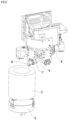
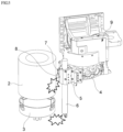
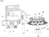
- FIG. 4 is a perspective view of a tool magazine for a machine tool according to the present disclosure
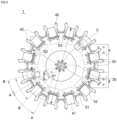
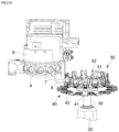
- FIG. 5 is a partial top plan view of FIG. 4
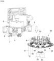
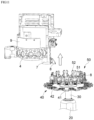
- FIGS. 6 to 8 are views illustrating a process of changing tools in a first tool receiving unit of the tool magazine for a machine tool according to an exemplary embodiment of the present disclosure
- FIGS. 9 to 11 are views illustrating a process of changing tools in a second tool receiving unit of the tool magazine for a machine tool according to the exemplary embodiment of the present disclosure.
- horizontal direction means a transverse direction in the same member
- vertical direction means a height direction in the same member orthogonal to the horizontal direction
- width direction means a longitudinal direction in the same member orthogonal to the horizontal direction and the vertical direction.
- the tool magazine 1 for a machine tool includes a base unit 10, a support unit 20, a rotary shaft unit 30, a first tool receiving unit 40, and a second tool receiving unit 50.
- the tool magazine 1 for a machine tool according to the present disclosure may be applied to all machine tools that change tools by moving spindle heads.
- FIGS. 4 to 11 illustrate a vertical type turning center as an example, but the present disclosure is not necessarily limited thereto.
- the tool magazine 1 for a machine tool according to the present disclosure may be applied to all machine tools in which a gripper of a tool magazine presses and clamps a tool by moving a spindle head in order to change the tools.
- the base unit 10 is installed in a part of a space in which a spindle head 9 moves.
- the base unit 10 is made of a metal material and installed at one side of the machine tool to perform a function of stably supporting the tool magazine.
- the support unit 20 is installed to be perpendicular to the base unit 10. That is, the support unit 20 is installed to extend upward in a vertical direction from an upper surface of the base unit 10.
- the support unit 20 is illustrated as having a hollow and cylindrical shape in FIGS. 4 to 11 , but the present disclosure is not necessarily limited thereto.
- the support unit 20 may have various shapes such as a hollow and rectangular parallelepiped shape.
- a drive unit is installed in the support unit 20 in order to operate the rotary shaft unit 30 to be described below.
- the drive unit is configured as a servo motor or a motor and operated by an instruction from a PLC or a numerical control unit.
- the numerical control unit includes numerical control (NC) or computerized numerical control (CNC) and is embedded with various types of numerical control programs. That is, the numerical control unit is embedded with a program for operating the servo motor which is the drive unit and a program for operating the tools, and the corresponding program is automatically loaded and executed based on the operation of the numerical control unit. In addition, the numerical control unit communicates with a main operating unit and the PLC through a predetermined protocol.
- NC numerical control
- CNC computerized numerical control
- the main operating unit includes a screen display program and a data input program in accordance with a selection of a screen display and performs a function of displaying a software switch on a display screen in accordance with an output of the screen display program and a function of recognizing an ON/OFF state of the software switch and making an instruction about an input and an output for an operation of the machine.
- the main operating unit has a monitor installed in or at one side of a housing or a casing of the machine tool and capable of displaying multifunctional switches or buttons and various types of information, but the present invention is not necessarily limited thereto.
- the PLC (programmable logic controller) communicates with the numerical control unit or the main operating unit through the predetermined protocol and serves to make a control instruction through this communication. That is, the PLC operates by receiving a control instruction based on the numerical control program for the numerical control unit or the main operating unit.
- the rotary shaft unit 30 is rotatably installed in the support unit 20.
- the rotary shaft unit 30 is inserted and installed into the support unit 20 so that the rotary shaft unit 30 is rotated by the drive unit installed in the support unit 20 and an upper portion of the rotary shaft unit 30 is exposed to the outside in order to prevent damage and reduce a size of the tool magazine, but the present disclosure is not necessarily limited thereto.
- the first tool receiving unit 40 is rotatably installed on the rotary shaft unit 30.
- the first tool receiving unit 40 may receive a plurality of tools disposed radially based on a rotation center C of the rotary shaft unit.
- the tools are received by a plurality of first gripper parts 42 to be described below.
- the second tool receiving unit 50 is rotatably installed on the rotary shaft unit 30 so as to be spaced apart vertically from an upper side of the first tool receiving unit 40.
- the second tool receiving unit 50 may receive a plurality of tools disposed radially based on the rotation center C of the rotary shaft unit. The tools are received by a plurality of second gripper parts 52 to be described below.
- the second tool receiving unit 50 and the first tool receiving unit 40 are installed on the rotary shaft unit 30 so that a tool receiving direction of the second tool receiving unit 50 is orthogonal to a tool receiving direction of the first tool receiving unit 40. Therefore, the tool received by the first tool receiving unit 40 and the tool received by the second tool receiving unit 50 may be installed to be orthogonal to each other, but the present disclosure is not necessarily limited thereto.
- the spindle head may easily change the external diameter machining tool (vertical tool) received by the first tool receiving unit and the internal diameter machining tool (horizontal tool) received by the second tool receiving unit while moving in the horizontal direction or the vertical direction, and a large number of tools are received by the first tool receiving unit and the second tool receiving unit, thereby minimizing a space occupied by the tool magazine.
- the spindle head may easily change the internal diameter machining tool and the external diameter machining tool while moving in the horizontal direction and the vertical direction, thereby minimizing non-machining time and improving productivity of the machine tool.
- the first tool receiving unit 40 of the tool magazine 1 for a machine tool includes a first main body part 41 and the first gripper parts 42.
- the first main body part 41 defines an external shape of the first tool receiving unit 40.
- the first main body part 41 penetrates the rotation center C of the rotary shaft unit and is rotatably installed on the rotary shaft unit 30.
- the first main body part 41 is formed in a circular plate shape, but the present disclosure is not necessarily limited thereto.
- the plurality of first gripper parts 42 is installed on the first main body part 41 and disposed radially at a predetermined angle based on the rotation center C of the rotary shaft unit, and the first gripper part 42 clamps the tool by pressing the tool. That is, the first gripper part 42 presses a pair of fingers by using a pressing means such as an elastic member and clamps the tool by pressing force.
- the plurality of first gripper parts 42 is installed on the first main body part 41 such that based on the rotation center C of the rotary shaft unit, 90 first gripper parts 42 are disposed at an angle of 4 degrees with respect to one another, 36 first gripper parts 42 are disposed at an angle of 10 degrees with respect to one another, 24 first gripper parts 42 are disposed at an angle of 15 degrees with respect to one another, 12 first gripper parts 42 are disposed at an angle of 30 degrees with respect to one another, 8 first gripper parts 42 are disposed at an angle of 45 degrees with respect to one another, 6 first gripper parts 42 are disposed at an angle of 60 degrees with respect to one another, 4 first gripper parts 42 are disposed at an angle of 90 degrees with respect to one another, 3 first gripper parts 42 are disposed at an angle of 120 degrees with respect to one another, or 2 first gripper parts 42 are disposed at an angle of 180 degrees with respect to each other.
- the plurality of first gripper parts 42 is installed at a predetermined angle in accordance with the number of tools required to be
- the second tool receiving unit 50 of the tool magazine 1 for a machine tool includes a second main body part 51 and the second gripper parts 52.
- the second main body part 51 defines an external shape of the second tool receiving unit 50.
- the second main body part 51 is spaced apart from the upper side of the first main body part 41 vertically upward based on the rotary shaft unit and rotatable installed on the rotary shaft unit 30 while penetrating the rotation center C of the rotary shaft unit. That is, the second main body part 51 is rotatably installed on the rotary shaft unit 30 and spaced apart from the first main body part 41 vertically upward based on the rotary shaft unit 30, and the second main body part 51 and the first main body part 41 are concentric about the rotation center C of the rotary shaft unit.
- the plurality of second gripper parts 52 is installed on the second main body part 51 and disposed radially at a predetermined angle based on the rotation center C of the rotary shaft unit, and the second gripper part 42 clamps the tool by pressing the tool. That is, the second gripper part 52 presses a pair of fingers by using a pressing means such as an elastic member and clamps the tool by pressing force.
- the plurality of second gripper parts 52 is installed on the second main body part 51 such that based on the rotation center C of the rotary shaft unit, 90 second gripper parts 42 are disposed at an angle of 4 degrees with respect to one another, 36 second gripper parts 42 are disposed at an angle of 10 degrees with respect to one another, 24 second gripper parts 42 are disposed at an angle of 15 degrees with respect to one another, 12 second gripper parts 42 are disposed at an angle of 30 degrees with respect to one another, 8 second gripper parts 42 are disposed at an angle of 45 degrees with respect to one another, 6 second gripper parts 42 are disposed at an angle of 60 degrees with respect to one another, 4 second gripper parts 42 are disposed at an angle of 90 degrees with respect to one another, 3 second gripper parts 42 are disposed at an angle of 120 degrees with respect to one another, or 2 second gripper parts 42 are disposed at an angle of 180 degrees with respect to each other.
- the plurality of second gripper parts 42 is installed at a predetermined angle in accordance with the number of tools required to be
- the internal diameter machining tool (vertical tool) for performing internal diameter machining on a workpiece may be installed on the first gripper part 42 of the first tool receiving unit 40 of the tool magazine 1 for a machine tool according to the exemplary embodiment of the present disclosure, and the external diameter machining tool (horizontal tool) for performing external diameter machining on a workpiece may be installed on the second gripper part 52 of the second tool receiving unit 50.
- the tool installed on the first gripper part 42 of the first tool receiving unit 40 of the tool magazine 1 for a machine tool may be changed as the spindle head 9 moves in the vertical direction
- the tool installed on the second gripper part 50 of the second tool receiving unit 50 may be changed as the spindle head 9 moves in the horizontal direction.
- the tool receiving units are stacked in multiple stages, such that the number of types of tools to be mounted on the tool magazine may be increased, non-machining time may be reduced, and the tools to be changed may be easily stored, thereby achieving convenience and safety for an operator, reducing a size of the tool magazine, and making the machine tool compact.
- a diameter D1 of the first main body part of the first tool receiving unit 40 of the tool magazine 1 for a machine tool is larger than a diameter D2 of the second main body part of the second tool receiving unit 50 (D1 > D2). If the diameter D1 of the first main body part is equal to or smaller than the diameter D2 of the second main body part (D1 ⁇ D2), the spindle head cannot change, due to interference, the vertical tool (internal diameter machining tool) and the horizontal tool (external diameter machining tool) while moving in the vertical direction and the horizontal direction. Therefore, it is possible to maximize convenience and ease of change of the internal diameter machining tool and the external diameter machining tool and to achieve convenience for a user.
- the internal diameter machining tool (vertical tool) for performing internal diameter machining on a workpiece may be installed on the first gripper part 42 of the first tool receiving unit 40 of the tool magazine 1 for a machine tool according to the exemplary embodiment of the present disclosure, and the external diameter machining tool (horizontal tool) for performing external diameter machining on a workpiece may be installed on the second gripper part 52 of the second tool receiving unit 50.
- the internal diameter machining tool and the external diameter machining tool may be simultaneously used and easily changed, such that stability and reliability of the machine tool may be improved, and the plurality of tools may be stored and the external diameter machining tool and the internal diameter machining tool may be easily changed, such that the broken tool may be quickly replaced, machining precision of the machine tool may be improved, and satisfaction of consumers may be increased.
- the first gripper parts 42 are radially disposed on the first main body part 41 and the second gripper parts 52 are radially disposed on the second main body part 51 so that a centerline A of each of the first gripper parts 42 of the first tool receiving unit 40 of the tool magazine 1 for a machine tool according to the exemplary embodiment of the present disclosure and a centerline B of each of the second gripper parts 52 intersect each other based on the rotation center C.
- the first tool receiving unit 40 and the second tool receiving unit 50 may receive the same number of tools, such that the number of tools to be stored is increased, thereby achieving convenience for a user, reducing the time required to change the tools, and thus improving productivity.
- the respective first gripper parts 42 are radially disposed on the first main body part 41 and the respective second gripper parts 52 are radially disposed on the second main body part 51 so that an angle ⁇ between the centerlines of the first gripper parts of the first tool receiving unit 40 of the tool magazine 1 for a machine tool according to the exemplary embodiment of the present disclosure is equal to an angle ⁇ between the centerlines of the second gripper parts of the second tool receiving unit 50.
- the 12 vertical tools may be installed on the first tool receiving unit 40 and the 12 horizontal tools (external diameter machining tools) may be installed on the second tool receiving unit 50, but the present disclosure is not necessarily limited thereto.
- the first tool receiving unit 40 and the second tool receiving unit 50 may be uniformly and constantly disposed, such that the interference may be minimized when the spindle head moves in the horizontal direction and the vertical direction, thereby smoothly, accurately, and easily changing the horizontal tools (external diameter machining tools) and the vertical tools (internal diameter machining tools), thereby improving productivity and achieving convenience for a user.
- the first gripper parts 42 are radially disposed on the first main body part 41 and the second gripper parts 52 are radially disposed on the second main body part 52 so that a constant angle ⁇ is formed between the centerline A of the first gripper part 42 of the first tool receiving unit 40 of the tool magazine 1 for a machine tool according to the exemplary embodiment of the present disclosure and the centerline B of the second gripper part 52 of the second tool receiving unit 50, which is adjacent to the first gripper part 42.
- the angle ⁇ between the centerline A of the first gripper part 42 and the centerline B of the second gripper part 52 of the second tool receiving unit 50, which is adjacent to the first gripper part 42, is constant as 15 degrees
- the 12 vertical tools internal diameter machining tools
- the 12 horizontal tools external diameter machining tools
- the spindle head may easily change the internal diameter machining tools and the external diameter machining tools while moving in the horizontal direction and the vertical direction, such that non-machining time may be minimized and productivity of the machine tool may be improved, and the tools to be changed may be easily stored, such that convenience and safety for an operator may be achieved, and a size of the tool magazine may be reduced to implement the compact machine tool.
- the tool magazine 1 for a machine tool may further include a third tool receiving unit.
- the third tool receiving unit is rotatably installed on the rotary shaft unit so as to be spaced apart vertically from an upper side of the second tool receiving unit 50.
- the third tool receiving unit may receive a plurality of tools disposed radially based on the rotation center of the rotary shaft unit. The tools are received by a plurality of third gripper parts of the third tool receiving unit, respectively.
- the third tool receiving unit is installed on the rotary unit so that a tool receiving direction of the third tool receiving unit is in parallel with the tool receiving direction of the second tool receiving unit.
- the first tool receiving unit 40 receives the vertical tools (internal diameter machining tools)
- the second tool receiving unit 50 receives the horizontal tools (external diameter machining tools)
- the third tool receiving unit receives the horizontal tools (external diameter machining tools), such that the tools received by the first tool receiving unit and the second tool receiving unit are orthogonal to each other, the tools received by the first tool receiving unit and the third tool receiving unit are orthogonal to each other, and the tools received by the second tool receiving unit and the third tool receiving unit are in parallel with each other.
- a diameter of the third main body part of the third tool receiving unit is smaller than a diameter of the second main body part of the second tool receiving unit. Therefore, the spindle head may easily change the vertical tools and the horizontal tools without interference while moving in the vertical direction and the horizontal direction, such that non-machining time is reduced, thereby improving productivity of the machine tool.
- the plurality of required tool may be additionally received, thereby achieving convenience for a user.
- the first, second, and third tool receiving units are stacked in multiple stages, such that a space occupied by the tool magazine is minimized and a size of the tool magazine is reduced, thereby making the machine tool compact.
- the first main body part 41 is rotated by the operation of the drive unit in the support unit 20 under control of the numerical control unit or the PLC, such that the internal diameter machining tool 6 to be replaced is positioned at a desired position.
- a tool post 4 is also rotated under control of the numerical control unit or the PLC, such that the internal diameter machining tool holder 5 for fastening the corresponding internal diameter machining tool 6 is rotated and positioned at a desired position.
- the tool post 4 having the external diameter machining tool holder 7 and the internal diameter machining tool holder 5 and the spindle head 9 for operating the tool post 4 are moved vertically downward in order to mount the internal diameter machining tool 6 on the internal diameter machining tool holder 5.
- the internal diameter machining tool 6 of the corresponding first gripper part 42 on the first main body part 41 is inserted and fastened into the corresponding internal diameter machining tool holder 5.
- the spindle head 9 moves to the left in the horizontal direction, the internal diameter machining may be smoothly and quickly performed in a state in which the internal diameter machining tool 6 is inserted into the desired internal diameter machining tool holder 5.
- the second main body part 51 is rotated by the operation of the drive unit in the support unit 20 under control of the numerical control unit or the PLC, such that the external diameter machining tool 8 to be replaced is positioned at a desired position.
- the tool post 4 is also rotated under control of the numerical control unit or the PLC, such that the external diameter machining tool holder 7 for fastening the corresponding external diameter machining tool 8 is rotated and positioned at a desired position.
- the tool post 4 having the external diameter machining tool holder 7 and the internal diameter machining tool holder 5 and the spindle head 9 for operating the tool post 4 are moved to the right in the horizontal direction (the direction toward the tool magazine) in order to mount the external diameter machining tool 8 on the external diameter machining tool holder 7.
- the external diameter machining tool 8 of the corresponding second gripper part 52 on the second main body part 51 is inserted and fastened into the corresponding external diameter machining tool holder 7.
- the spindle head 9 moves upward in the vertical direction, the external diameter machining may be smoothly and quickly performed in a state in which the external diameter machining tool 8 is inserted into the desired external diameter machining tool holder 7.
- the tool receiving direction of the second tool receiving unit is orthogonal to the tool receiving direction of the first tool receiving unit
- the tools received by the second tool receiving unit and the first tool receiving unit are orthogonal to each other and disposed in multiple stages, such that the spindle head may easily change the internal diameter machining tools and the external diameter machining tools while moving in the horizontal direction and the vertical direction, thereby minimizing non-machining time, and thus improving productivity of the machine tool.
- the tools to be changed may be easily stored, thereby achieving convenience and safety for an operator, reducing a size of the tool magazine, and making the machine tool compact.
Landscapes
- Engineering & Computer Science (AREA)
- Mechanical Engineering (AREA)
- Automatic Tool Replacement In Machine Tools (AREA)
Claims (6)
- Werkzeugmagazin (1) für eine Werkzeugmaschine (2), wobei das Werkzeugmagazin (1) umfasst:eine Basiseinheit (10), die in einem Teil eines Raums installiert ist, in dem sich ein Spindelkopf (9) bewegt;eine Stützeinheit (20), die so installiert ist, dass sie senkrecht zu der Basiseinheit (10) verläuft;eine Drehwelleneinheit (30), die drehbar in der Stützeinheit (20) installiert ist;eine erste Werkzeugaufnahmeeinheit (40), die drehbar an der Drehwelleneinheit (30) installiert und dafür eingerichtet ist, mehrere Werkzeuge aufzunehmen, die radial auf der Basis einer Drehmitte (C) der Drehwelleneinheit (30) angeordnet sind; undeine zweite Werkzeugaufnahmeeinheit (50), die drehbar so an der Drehwelleneinheit (30) installiert ist, dass sie vertikal von einer Oberseite der ersten Werkzeugaufnahmeeinheit (40) beabstandet ist, und dafür eingerichtet ist, mehrere Werkzeuge aufzunehmen, die radial auf der Grundlage der Drehmitte (C) der Drehwelleneinheit (30) angeordnet sind,wobei eine Werkzeugaufnahmerichtung der zweiten Werkzeugaufnahmeeinheit (50) orthogonal zu einer Werkzeugaufnahmerichtung der ersten Werkzeugaufnahmeeinheit (40) verläuft,wobei die erste Werkzeugaufnahmeeinheit (40) umfasst:einen ersten Hauptkörperteil (41), der drehbar an der Drehwelleneinheit (30) installiert ist; undmehrere erste Greiferteile (42), die an dem ersten Hauptkörperteil (41) installiert sind, radial in einem zuvor festgelegten Winkel auf der Basis der Drehmitte (C) der Drehwelleneinheit (30) angeordnet sind und dafür eingerichtet sind, ein Werkzeug durch Drücken gegen das Werkzeug einzuspannen,dadurch gekennzeichnet, dass die zweite Werkzeugaufnahmeeinheit (50) umfasst:einen zweiten Hauptkörperteil (51), der drehbar so an der Drehwelleneinheit (30) installiert ist, dass er vertikal von einer Oberseite des ersten Hauptkörperteils (41) beabstandet ist; undmehrere zweite Greiferteile (52), die an dem zweiten Hauptkörperteil (51) installiert sind, radial in einem zuvor festgelegten Winkel auf der Basis der Drehmitte (C) der Drehwelleneinheit (30) angeordnet sind und dafür eingerichtet sind, ein Werkzeug durch Drücken gegen das Werkzeug einzuspannen,wobei die ersten Greiferteile (42) so an dem ersten Hauptkörperteil (41) angeordnet sind und die zweiten Greiferteile (52) so an dem zweiten Hauptkörperteil (51) angeordnet sind, dass eine Mittellinie jedes der ersten Greiferteile (42) und eine Mittellinie jedes der zweiten Greiferteile (52) einander auf der Basis der Rotationsmitte (C) schneiden,wobei ein Innendurchmesserbearbeitungswerkzeug zum Durchführen einer Innendurchmesserbearbeitung an einem Werkstück an dem ersten Greiferteil (42) installiert ist und ein Außendurchmesserbearbeitungswerkzeug zum Durchführen einer Außendurchmesserbearbeitung an einem Werkstück an dem zweiten Greiferteil (52) installiert ist.
- Werkzeugmagazin (1) nach Anspruch 1, wobei ein Durchmesser des ersten Hauptkörperteils (41) größer ist als ein Durchmesser des zweiten Hauptkörperteils (51).
- Werkzeugmagazin (1) nach Anspruch 1, wobei die ersten Greiferteile (42) so an dem ersten Hauptkörperteil (41) angeordnet sind und die zweiten Greiferteile (52) so an dem zweiten Hauptkörperteil (51) angeordnet sind, dass ein Winkel zwischen Mittellinien der ersten Greiferteile (42) gleich einem Winkel zwischen Mittellinien der zweiten Greiferteile (52) ist.
- Werkzeugmagazin (1) nach Anspruch 1, wobei die ersten Greiferteile (42) so an dem ersten Hauptkörperteil (41) angeordnet sind und die zweiten Greiferteile (52) so an dem zweiten Hauptkörperteil (51) angeordnet sind, dass ein konstanter Winkel zwischen einer Mittellinie des ersten Greiferteils (42) und einer Mittellinie des zweiten Greiferteils neben dem ersten Greiferteil (52) gebildet wird.
- Werkzeugmagazin (1) nach Anspruch 1, wobei ein an dem ersten Greiferteil (42) installiertes Werkzeug gewechselt werden kann, wenn sich der Spindelkopf (9) in einer vertikalen Richtung bewegt, und ein an dem zweiten Greiferteil (52) installiertes Werkzeug gewechselt werden kann, wenn sich der Spindelkopf (9) in einer horizontalen Richtung bewegt.
- Werkzeugmagazin (1) nach Anspruch 1, des Weiteren umfassend: eine dritte Werkzeugaufnahmeeinheit, die drehbar so an der Drehwelleneinheit (30) installiert ist, dass sie vertikal von einer Oberseite der zweiten Werkzeugaufnahmeeinheit (50) beabstandet ist, und dafür eingerichtet ist, mehrere Werkzeuge aufzunehmen, die radial auf der Grundlage der Drehmitte (C) der Drehwelleneinheit (30) angeordnet sind, wobei eine Werkzeugaufnahmerichtung der dritten Werkzeugaufnahmeeinheit parallel zu der Werkzeugaufnahmerichtung der zweiten Werkzeugaufnahmeeinheit (50) verläuft.
Applications Claiming Priority (2)
| Application Number | Priority Date | Filing Date | Title |
|---|---|---|---|
| KR1020180000641A KR20190083104A (ko) | 2018-01-03 | 2018-01-03 | 공작기계의 툴 매거진 |
| PCT/KR2018/016859 WO2019135561A1 (ko) | 2018-01-03 | 2018-12-28 | 공작기계의 툴 매거진 |
Publications (4)
| Publication Number | Publication Date |
|---|---|
| EP3733341A1 EP3733341A1 (de) | 2020-11-04 |
| EP3733341A4 EP3733341A4 (de) | 2021-10-20 |
| EP3733341C0 EP3733341C0 (de) | 2024-10-30 |
| EP3733341B1 true EP3733341B1 (de) | 2024-10-30 |
Family
ID=67144488
Family Applications (1)
| Application Number | Title | Priority Date | Filing Date |
|---|---|---|---|
| EP18898825.7A Active EP3733341B1 (de) | 2018-01-03 | 2018-12-28 | Werkzeugmagazin einer werkzeugmaschine |
Country Status (5)
| Country | Link |
|---|---|
| US (1) | US11433497B2 (de) |
| EP (1) | EP3733341B1 (de) |
| KR (1) | KR20190083104A (de) |
| CN (1) | CN111655424B (de) |
| WO (1) | WO2019135561A1 (de) |
Families Citing this family (7)
| Publication number | Priority date | Publication date | Assignee | Title |
|---|---|---|---|---|
| CN110389559A (zh) * | 2019-07-26 | 2019-10-29 | 北京工业大学 | 一种刀库性能与可靠性检测系统 |
| WO2021177619A1 (ko) * | 2020-03-03 | 2021-09-10 | 두산공작기계 주식회사 | 공작기계의 툴 매거진 및 이의 작동방법 |
| EP4122643B1 (de) * | 2020-03-23 | 2025-01-22 | DN Solutions Co., Ltd. | Bohrstangenwerkzeugwechsler und bohrstangenwerkzeugwechselverfahren damit |
| KR102494806B1 (ko) * | 2020-08-13 | 2023-02-06 | (주)피엔피 | 초박형 유리블록 커팅용 자동 툴 교환장치 |
| JP7577315B2 (ja) * | 2021-01-25 | 2024-11-05 | 株式会社オーエム製作所 | 自動工具交換装置 |
| CN113021046B (zh) * | 2021-03-29 | 2022-05-20 | 杨铁数控机床(苏州)有限公司 | 一种数控机床用伞形刀库 |
| CN118832204B (zh) * | 2024-07-26 | 2025-05-06 | 重庆市大足区川江金属制品厂 | 一种车床刀塔结构 |
Family Cites Families (23)
| Publication number | Priority date | Publication date | Assignee | Title |
|---|---|---|---|---|
| CH568130A5 (de) * | 1974-02-04 | 1975-10-31 | Knaus Reto | |
| DE2737225A1 (de) * | 1977-08-18 | 1979-02-22 | Heyligenstaedt & Co | Werkzeugmaschine mit einem revolverkopf zur aufnahme von werkzeugen |
| CH646085A5 (fr) * | 1980-03-07 | 1984-11-15 | Georges Moulin | Dispositif changeur automatique d'outils, pour une machine-outil a broche verticale ou horizontale. |
| FR2479060A1 (fr) * | 1980-03-26 | 1981-10-02 | Line Sa | Magasin d'outils pour dispositif de changement automatique d'outils |
| FR2515948A1 (fr) * | 1981-11-12 | 1983-05-13 | Pasquier Roger | Magasin-presentoir pour outils |
| SU1135593A1 (ru) * | 1983-10-03 | 1985-01-23 | Ульяновское Головное Специальное Конструкторское Бюро Тяжелых И Фрезерных Станков | Устройство дл автоматической смены инструмента |
| JPS6099541A (ja) * | 1983-11-02 | 1985-06-03 | Yoshikazu Sato | マシニングセンタの自動工具交換装置 |
| JPS60123240A (ja) * | 1983-12-02 | 1985-07-01 | Aioi Seiki Kk | マシニングセンタ−の工具交換装置 |
| FR2699100B1 (fr) * | 1992-12-15 | 1995-03-10 | Helis Sa | Machine-outil équipée d'un magasin d'outils à disques. |
| DE29604045U1 (de) * | 1996-03-05 | 1997-07-03 | Hüller Hille GmbH, 71636 Ludwigsburg | Werkzeugwechseleinrichtung |
| KR101235391B1 (ko) | 2005-12-22 | 2013-02-20 | 두산인프라코어 주식회사 | 더블 매거진의 공구전환부 포트 이탈 방지장치 |
| KR20080067037A (ko) * | 2007-01-15 | 2008-07-18 | (주)성우기전 | 수직 및 수평 양방향 자동공구교환장치 |
| JP5385036B2 (ja) * | 2009-07-15 | 2014-01-08 | オークマ株式会社 | 工具マガジン |
| GB2487520B (en) * | 2009-11-18 | 2013-01-09 | Komatsu Ntc Ltd | Tool magazine and machining center |
| DE102012201776A1 (de) * | 2012-02-07 | 2013-08-08 | Homag Holzbearbeitungssysteme Gmbh | Magazin zur Aufnahme von Bearbeitungswerkzeugen und/oder Bearbeitungsaggregaten |
| CN102975068B (zh) * | 2012-12-04 | 2016-04-27 | 齐重数控装备股份有限公司 | 大容量落地盘式升降刀库 |
| DE102014218899A1 (de) * | 2014-09-19 | 2016-03-24 | Homag Holzbearbeitungssysteme Gmbh | Greifeinrichtung für ein Bearbeitungswerkzeug, Speichersystem sowie Verfahren |
| CN204248532U (zh) * | 2014-12-03 | 2015-04-08 | 佛山市普拉迪数控科技有限公司 | 刀库后置换刀结构 |
| CN204413705U (zh) * | 2014-12-19 | 2015-06-24 | 大连意美机械有限公司 | 数控双柱立式车铣复合加工中心双层刀库 |
| CN104526431B (zh) * | 2015-01-03 | 2016-09-21 | 巨轮智能装备股份有限公司 | 双层圆盘式刀库装置 |
| KR101705436B1 (ko) | 2015-03-09 | 2017-02-09 | 김향곤 | 자동공구 교환장치용 툴매거진 |
| DE102015016680A1 (de) * | 2015-12-22 | 2017-06-22 | Mwa Magdeburger Werkzeugmaschinen & Automation Gmbh | Magazineinheit für Werkzeuge oder Werkstücke |
| CN107283202B (zh) * | 2017-08-15 | 2019-05-21 | 苏州谷夫道自动化科技有限公司 | 换刀机构、加工中心及用该加工中心的换刀方法 |
-
2018
- 2018-01-03 KR KR1020180000641A patent/KR20190083104A/ko not_active Withdrawn
- 2018-12-28 US US16/960,040 patent/US11433497B2/en active Active
- 2018-12-28 WO PCT/KR2018/016859 patent/WO2019135561A1/ko not_active Ceased
- 2018-12-28 CN CN201880088135.4A patent/CN111655424B/zh active Active
- 2018-12-28 EP EP18898825.7A patent/EP3733341B1/de active Active
Also Published As
| Publication number | Publication date |
|---|---|
| WO2019135561A1 (ko) | 2019-07-11 |
| US20210187681A1 (en) | 2021-06-24 |
| EP3733341A1 (de) | 2020-11-04 |
| CN111655424A (zh) | 2020-09-11 |
| EP3733341A4 (de) | 2021-10-20 |
| KR20190083104A (ko) | 2019-07-11 |
| CN111655424B (zh) | 2022-09-09 |
| EP3733341C0 (de) | 2024-10-30 |
| US11433497B2 (en) | 2022-09-06 |
Similar Documents
| Publication | Publication Date | Title |
|---|---|---|
| EP3733341B1 (de) | Werkzeugmagazin einer werkzeugmaschine | |
| US12202091B2 (en) | Automatic tool changer and control method therefor and machine tool including same | |
| EP3907039B1 (de) | Werkzeugmagazin einer werkzeugmaschine | |
| EP3907038B1 (de) | Werkzeugmaschine und verfahren zu deren betrieb | |
| US3710466A (en) | Machine tools and more particularly to data-controlled machine tools | |
| EP3736068B1 (de) | Revolverkopfwerkzeugstange einer werkzeugmaschine | |
| KR20220141530A (ko) | 공작기계의 멀티 팔레트 시스템 | |
| KR102562141B1 (ko) | 공작기계 | |
| KR102495718B1 (ko) | 공구 교환 제어장치 및 제어방법 | |
| US20230201965A1 (en) | Machine tool | |
| KR20240171743A (ko) | 공작기계의 매트릭스형 공구매거진장치 및 이의 제어방법 | |
| KR20230162480A (ko) | 암리스 자동공구교환장치 | |
| KR102890272B1 (ko) | 공작기계의 툴 매거진 및 이의 작동방법 | |
| KR102461865B1 (ko) | 터렛 공구대 장치 | |
| KR20240163266A (ko) | 공작기계의 특수공구 리턴 장치 및 리턴 방법 | |
| KR20210111551A (ko) | 공작기계의 툴 매거진 및 이의 작동방법 | |
| KR20250146668A (ko) | 공작기계 및 공작기계의 자동교환방법 | |
| KR20240159114A (ko) | 공작기계 | |
| KR20240159112A (ko) | 유니버셜 헤드 및 이의 제어방법 | |
| KR20250157112A (ko) | 공작기계의 매트릭스형 공구매거진장치 및 이의 제어방법 | |
| JPH04240056A (ja) | 工作機械 | |
| KR20250157117A (ko) | 공작기계 및 공작기계의 작동방법 | |
| KR20240172435A (ko) | 공작기계의 테이블 장치 | |
| KR20240169735A (ko) | 공작기계의 자동공구교환장치 | |
| KR20220142676A (ko) | 공작기계의 자동공구교환장치 |
Legal Events
| Date | Code | Title | Description |
|---|---|---|---|
| STAA | Information on the status of an ep patent application or granted ep patent |
Free format text: STATUS: THE INTERNATIONAL PUBLICATION HAS BEEN MADE |
|
| PUAI | Public reference made under article 153(3) epc to a published international application that has entered the european phase |
Free format text: ORIGINAL CODE: 0009012 |
|
| STAA | Information on the status of an ep patent application or granted ep patent |
Free format text: STATUS: REQUEST FOR EXAMINATION WAS MADE |
|
| 17P | Request for examination filed |
Effective date: 20200729 |
|
| AK | Designated contracting states |
Kind code of ref document: A1 Designated state(s): AL AT BE BG CH CY CZ DE DK EE ES FI FR GB GR HR HU IE IS IT LI LT LU LV MC MK MT NL NO PL PT RO RS SE SI SK SM TR |
|
| AX | Request for extension of the european patent |
Extension state: BA ME |
|
| DAV | Request for validation of the european patent (deleted) | ||
| DAX | Request for extension of the european patent (deleted) | ||
| A4 | Supplementary search report drawn up and despatched |
Effective date: 20210920 |
|
| RIC1 | Information provided on ipc code assigned before grant |
Ipc: B23Q 3/157 20060101ALI20210914BHEP Ipc: B23Q 3/155 20060101AFI20210914BHEP |
|
| RAP3 | Party data changed (applicant data changed or rights of an application transferred) |
Owner name: DN SOLUTIONS CO., LTD. |
|
| GRAP | Despatch of communication of intention to grant a patent |
Free format text: ORIGINAL CODE: EPIDOSNIGR1 |
|
| STAA | Information on the status of an ep patent application or granted ep patent |
Free format text: STATUS: GRANT OF PATENT IS INTENDED |
|
| INTG | Intention to grant announced |
Effective date: 20240523 |
|
| GRAS | Grant fee paid |
Free format text: ORIGINAL CODE: EPIDOSNIGR3 |
|
| GRAA | (expected) grant |
Free format text: ORIGINAL CODE: 0009210 |
|
| STAA | Information on the status of an ep patent application or granted ep patent |
Free format text: STATUS: THE PATENT HAS BEEN GRANTED |
|
| AK | Designated contracting states |
Kind code of ref document: B1 Designated state(s): AL AT BE BG CH CY CZ DE DK EE ES FI FR GB GR HR HU IE IS IT LI LT LU LV MC MK MT NL NO PL PT RO RS SE SI SK SM TR |
|
| REG | Reference to a national code |
Ref country code: GB Ref legal event code: FG4D |
|
| REG | Reference to a national code |
Ref country code: CH Ref legal event code: EP |
|
| REG | Reference to a national code |
Ref country code: DE Ref legal event code: R096 Ref document number: 602018076117 Country of ref document: DE |
|
| REG | Reference to a national code |
Ref country code: IE Ref legal event code: FG4D |
|
| U01 | Request for unitary effect filed |
Effective date: 20241119 |
|
| U07 | Unitary effect registered |
Designated state(s): AT BE BG DE DK EE FI FR IT LT LU LV MT NL PT RO SE SI Effective date: 20241125 |
|
| PGFP | Annual fee paid to national office [announced via postgrant information from national office to epo] |
Ref country code: GB Payment date: 20241212 Year of fee payment: 7 |
|
| U20 | Renewal fee for the european patent with unitary effect paid |
Year of fee payment: 7 Effective date: 20241220 |
|
| PG25 | Lapsed in a contracting state [announced via postgrant information from national office to epo] |
Ref country code: IS Free format text: LAPSE BECAUSE OF FAILURE TO SUBMIT A TRANSLATION OF THE DESCRIPTION OR TO PAY THE FEE WITHIN THE PRESCRIBED TIME-LIMIT Effective date: 20250228 Ref country code: HR Free format text: LAPSE BECAUSE OF FAILURE TO SUBMIT A TRANSLATION OF THE DESCRIPTION OR TO PAY THE FEE WITHIN THE PRESCRIBED TIME-LIMIT Effective date: 20241030 |
|
| PG25 | Lapsed in a contracting state [announced via postgrant information from national office to epo] |
Ref country code: ES Free format text: LAPSE BECAUSE OF FAILURE TO SUBMIT A TRANSLATION OF THE DESCRIPTION OR TO PAY THE FEE WITHIN THE PRESCRIBED TIME-LIMIT Effective date: 20241030 |
|
| PG25 | Lapsed in a contracting state [announced via postgrant information from national office to epo] |
Ref country code: NO Free format text: LAPSE BECAUSE OF FAILURE TO SUBMIT A TRANSLATION OF THE DESCRIPTION OR TO PAY THE FEE WITHIN THE PRESCRIBED TIME-LIMIT Effective date: 20250130 |
|
| PG25 | Lapsed in a contracting state [announced via postgrant information from national office to epo] |
Ref country code: GR Free format text: LAPSE BECAUSE OF FAILURE TO SUBMIT A TRANSLATION OF THE DESCRIPTION OR TO PAY THE FEE WITHIN THE PRESCRIBED TIME-LIMIT Effective date: 20250131 |
|
| PG25 | Lapsed in a contracting state [announced via postgrant information from national office to epo] |
Ref country code: PL Free format text: LAPSE BECAUSE OF FAILURE TO SUBMIT A TRANSLATION OF THE DESCRIPTION OR TO PAY THE FEE WITHIN THE PRESCRIBED TIME-LIMIT Effective date: 20241030 |
|
| PG25 | Lapsed in a contracting state [announced via postgrant information from national office to epo] |
Ref country code: RS Free format text: LAPSE BECAUSE OF FAILURE TO SUBMIT A TRANSLATION OF THE DESCRIPTION OR TO PAY THE FEE WITHIN THE PRESCRIBED TIME-LIMIT Effective date: 20250130 |
|
| PG25 | Lapsed in a contracting state [announced via postgrant information from national office to epo] |
Ref country code: SM Free format text: LAPSE BECAUSE OF FAILURE TO SUBMIT A TRANSLATION OF THE DESCRIPTION OR TO PAY THE FEE WITHIN THE PRESCRIBED TIME-LIMIT Effective date: 20241030 |
|
| PG25 | Lapsed in a contracting state [announced via postgrant information from national office to epo] |
Ref country code: MC Free format text: LAPSE BECAUSE OF FAILURE TO SUBMIT A TRANSLATION OF THE DESCRIPTION OR TO PAY THE FEE WITHIN THE PRESCRIBED TIME-LIMIT Effective date: 20241030 |
|
| PG25 | Lapsed in a contracting state [announced via postgrant information from national office to epo] |
Ref country code: SK Free format text: LAPSE BECAUSE OF FAILURE TO SUBMIT A TRANSLATION OF THE DESCRIPTION OR TO PAY THE FEE WITHIN THE PRESCRIBED TIME-LIMIT Effective date: 20241030 |
|
| PG25 | Lapsed in a contracting state [announced via postgrant information from national office to epo] |
Ref country code: CZ Free format text: LAPSE BECAUSE OF FAILURE TO SUBMIT A TRANSLATION OF THE DESCRIPTION OR TO PAY THE FEE WITHIN THE PRESCRIBED TIME-LIMIT Effective date: 20241030 |
|
| REG | Reference to a national code |
Ref country code: CH Ref legal event code: PL |
|
| PLBE | No opposition filed within time limit |
Free format text: ORIGINAL CODE: 0009261 |
|
| STAA | Information on the status of an ep patent application or granted ep patent |
Free format text: STATUS: NO OPPOSITION FILED WITHIN TIME LIMIT |
|
| 26N | No opposition filed |
Effective date: 20250731 |
|
| PG25 | Lapsed in a contracting state [announced via postgrant information from national office to epo] |
Ref country code: CH Free format text: LAPSE BECAUSE OF NON-PAYMENT OF DUE FEES Effective date: 20241231 |
|
| PG25 | Lapsed in a contracting state [announced via postgrant information from national office to epo] |
Ref country code: IE Free format text: LAPSE BECAUSE OF NON-PAYMENT OF DUE FEES Effective date: 20241228 |