EP3732069B1 - Wärmeübertragungseinrichtung für die kältebereitstellung in kühlfahrzeugen, deren kraftfahrzeugmotor mit lng angetrieben wird - Google Patents
Wärmeübertragungseinrichtung für die kältebereitstellung in kühlfahrzeugen, deren kraftfahrzeugmotor mit lng angetrieben wird Download PDFInfo
- Publication number
- EP3732069B1 EP3732069B1 EP18836452.5A EP18836452A EP3732069B1 EP 3732069 B1 EP3732069 B1 EP 3732069B1 EP 18836452 A EP18836452 A EP 18836452A EP 3732069 B1 EP3732069 B1 EP 3732069B1
- Authority
- EP
- European Patent Office
- Prior art keywords
- lng
- heat exchanger
- heat
- heat transfer
- intermediate medium
- Prior art date
- Legal status (The legal status is an assumption and is not a legal conclusion. Google has not performed a legal analysis and makes no representation as to the accuracy of the status listed.)
- Active
Links
Images
Classifications
-
- B—PERFORMING OPERATIONS; TRANSPORTING
- B60—VEHICLES IN GENERAL
- B60H—ARRANGEMENTS OF HEATING, COOLING, VENTILATING OR OTHER AIR-TREATING DEVICES SPECIALLY ADAPTED FOR PASSENGER OR GOODS SPACES OF VEHICLES
- B60H1/00—Heating, cooling or ventilating devices
- B60H1/32—Cooling devices
- B60H1/3202—Cooling devices using evaporation, i.e. not including a compressor, e.g. involving fuel or water evaporation
-
- F—MECHANICAL ENGINEERING; LIGHTING; HEATING; WEAPONS; BLASTING
- F28—HEAT EXCHANGE IN GENERAL
- F28F—DETAILS OF HEAT-EXCHANGE AND HEAT-TRANSFER APPARATUS, OF GENERAL APPLICATION
- F28F1/00—Tubular elements; Assemblies of tubular elements
- F28F1/003—Multiple wall conduits, e.g. for leak detection
-
- B—PERFORMING OPERATIONS; TRANSPORTING
- B60—VEHICLES IN GENERAL
- B60H—ARRANGEMENTS OF HEATING, COOLING, VENTILATING OR OTHER AIR-TREATING DEVICES SPECIALLY ADAPTED FOR PASSENGER OR GOODS SPACES OF VEHICLES
- B60H1/00—Heating, cooling or ventilating devices
- B60H1/00321—Heat exchangers for air-conditioning devices
- B60H1/00328—Heat exchangers for air-conditioning devices of the liquid-air type
-
- B—PERFORMING OPERATIONS; TRANSPORTING
- B60—VEHICLES IN GENERAL
- B60H—ARRANGEMENTS OF HEATING, COOLING, VENTILATING OR OTHER AIR-TREATING DEVICES SPECIALLY ADAPTED FOR PASSENGER OR GOODS SPACES OF VEHICLES
- B60H1/00—Heating, cooling or ventilating devices
- B60H1/00321—Heat exchangers for air-conditioning devices
- B60H1/00335—Heat exchangers for air-conditioning devices of the gas-air type
-
- B—PERFORMING OPERATIONS; TRANSPORTING
- B60—VEHICLES IN GENERAL
- B60H—ARRANGEMENTS OF HEATING, COOLING, VENTILATING OR OTHER AIR-TREATING DEVICES SPECIALLY ADAPTED FOR PASSENGER OR GOODS SPACES OF VEHICLES
- B60H1/00—Heating, cooling or ventilating devices
- B60H1/32—Cooling devices
- B60H1/3204—Cooling devices using compression
- B60H1/3228—Cooling devices using compression characterised by refrigerant circuit configurations
- B60H1/32281—Cooling devices using compression characterised by refrigerant circuit configurations comprising a single secondary circuit, e.g. at evaporator or condenser side
-
- F—MECHANICAL ENGINEERING; LIGHTING; HEATING; WEAPONS; BLASTING
- F17—STORING OR DISTRIBUTING GASES OR LIQUIDS
- F17C—VESSELS FOR CONTAINING OR STORING COMPRESSED, LIQUEFIED OR SOLIDIFIED GASES; FIXED-CAPACITY GAS-HOLDERS; FILLING VESSELS WITH, OR DISCHARGING FROM VESSELS, COMPRESSED, LIQUEFIED, OR SOLIDIFIED GASES
- F17C9/00—Methods or apparatus for discharging liquefied or solidified gases from vessels not under pressure
- F17C9/02—Methods or apparatus for discharging liquefied or solidified gases from vessels not under pressure with change of state, e.g. vaporisation
- F17C9/04—Recovery of thermal energy
-
- F—MECHANICAL ENGINEERING; LIGHTING; HEATING; WEAPONS; BLASTING
- F28—HEAT EXCHANGE IN GENERAL
- F28D—HEAT-EXCHANGE APPARATUS, NOT PROVIDED FOR IN ANOTHER SUBCLASS, IN WHICH THE HEAT-EXCHANGE MEDIA DO NOT COME INTO DIRECT CONTACT
- F28D15/00—Heat-exchange apparatus with the intermediate heat-transfer medium in closed tubes passing into or through the conduit walls ; Heat-exchange apparatus employing intermediate heat-transfer medium or bodies
-
- F—MECHANICAL ENGINEERING; LIGHTING; HEATING; WEAPONS; BLASTING
- F28—HEAT EXCHANGE IN GENERAL
- F28D—HEAT-EXCHANGE APPARATUS, NOT PROVIDED FOR IN ANOTHER SUBCLASS, IN WHICH THE HEAT-EXCHANGE MEDIA DO NOT COME INTO DIRECT CONTACT
- F28D7/00—Heat-exchange apparatus having stationary tubular conduit assemblies for both heat-exchange media, the media being in contact with different sides of a conduit wall
- F28D7/16—Heat-exchange apparatus having stationary tubular conduit assemblies for both heat-exchange media, the media being in contact with different sides of a conduit wall the conduits being arranged in parallel spaced relation
- F28D7/1607—Heat-exchange apparatus having stationary tubular conduit assemblies for both heat-exchange media, the media being in contact with different sides of a conduit wall the conduits being arranged in parallel spaced relation with particular pattern of flow of the heat exchange media, e.g. change of flow direction
-
- F—MECHANICAL ENGINEERING; LIGHTING; HEATING; WEAPONS; BLASTING
- F28—HEAT EXCHANGE IN GENERAL
- F28F—DETAILS OF HEAT-EXCHANGE AND HEAT-TRANSFER APPARATUS, OF GENERAL APPLICATION
- F28F23/00—Features relating to the use of intermediate heat-exchange materials, e.g. selection of compositions
- F28F23/02—Arrangements for obtaining or maintaining same in a liquid state
-
- F—MECHANICAL ENGINEERING; LIGHTING; HEATING; WEAPONS; BLASTING
- F28—HEAT EXCHANGE IN GENERAL
- F28F—DETAILS OF HEAT-EXCHANGE AND HEAT-TRANSFER APPARATUS, OF GENERAL APPLICATION
- F28F9/00—Casings; Header boxes; Auxiliary supports for elements; Auxiliary members within casings
- F28F9/02—Header boxes; End plates
- F28F9/0236—Header boxes; End plates floating elements
- F28F9/0239—Header boxes; End plates floating elements floating header boxes
-
- B—PERFORMING OPERATIONS; TRANSPORTING
- B60—VEHICLES IN GENERAL
- B60H—ARRANGEMENTS OF HEATING, COOLING, VENTILATING OR OTHER AIR-TREATING DEVICES SPECIALLY ADAPTED FOR PASSENGER OR GOODS SPACES OF VEHICLES
- B60H1/00—Heating, cooling or ventilating devices
- B60H1/00007—Combined heating, ventilating, or cooling devices
- B60H1/00014—Combined heating, ventilating, or cooling devices for load cargos on load transporting vehicles
-
- F—MECHANICAL ENGINEERING; LIGHTING; HEATING; WEAPONS; BLASTING
- F17—STORING OR DISTRIBUTING GASES OR LIQUIDS
- F17C—VESSELS FOR CONTAINING OR STORING COMPRESSED, LIQUEFIED OR SOLIDIFIED GASES; FIXED-CAPACITY GAS-HOLDERS; FILLING VESSELS WITH, OR DISCHARGING FROM VESSELS, COMPRESSED, LIQUEFIED, OR SOLIDIFIED GASES
- F17C2221/00—Handled fluid, in particular type of fluid
- F17C2221/03—Mixtures
- F17C2221/032—Hydrocarbons
- F17C2221/033—Methane, e.g. natural gas, CNG, LNG, GNL, GNC, PLNG
-
- F—MECHANICAL ENGINEERING; LIGHTING; HEATING; WEAPONS; BLASTING
- F17—STORING OR DISTRIBUTING GASES OR LIQUIDS
- F17C—VESSELS FOR CONTAINING OR STORING COMPRESSED, LIQUEFIED OR SOLIDIFIED GASES; FIXED-CAPACITY GAS-HOLDERS; FILLING VESSELS WITH, OR DISCHARGING FROM VESSELS, COMPRESSED, LIQUEFIED, OR SOLIDIFIED GASES
- F17C2223/00—Handled fluid before transfer, i.e. state of fluid when stored in the vessel or before transfer from the vessel
- F17C2223/01—Handled fluid before transfer, i.e. state of fluid when stored in the vessel or before transfer from the vessel characterised by the phase
- F17C2223/0146—Two-phase
- F17C2223/0153—Liquefied gas, e.g. LPG, GPL
- F17C2223/0161—Liquefied gas, e.g. LPG, GPL cryogenic, e.g. LNG, GNL, PLNG
-
- F—MECHANICAL ENGINEERING; LIGHTING; HEATING; WEAPONS; BLASTING
- F17—STORING OR DISTRIBUTING GASES OR LIQUIDS
- F17C—VESSELS FOR CONTAINING OR STORING COMPRESSED, LIQUEFIED OR SOLIDIFIED GASES; FIXED-CAPACITY GAS-HOLDERS; FILLING VESSELS WITH, OR DISCHARGING FROM VESSELS, COMPRESSED, LIQUEFIED, OR SOLIDIFIED GASES
- F17C2225/00—Handled fluid after transfer, i.e. state of fluid after transfer from the vessel
- F17C2225/01—Handled fluid after transfer, i.e. state of fluid after transfer from the vessel characterised by the phase
- F17C2225/0107—Single phase
- F17C2225/0123—Single phase gaseous, e.g. CNG, GNC
-
- F—MECHANICAL ENGINEERING; LIGHTING; HEATING; WEAPONS; BLASTING
- F17—STORING OR DISTRIBUTING GASES OR LIQUIDS
- F17C—VESSELS FOR CONTAINING OR STORING COMPRESSED, LIQUEFIED OR SOLIDIFIED GASES; FIXED-CAPACITY GAS-HOLDERS; FILLING VESSELS WITH, OR DISCHARGING FROM VESSELS, COMPRESSED, LIQUEFIED, OR SOLIDIFIED GASES
- F17C2227/00—Transfer of fluids, i.e. method or means for transferring the fluid; Heat exchange with the fluid
- F17C2227/03—Heat exchange with the fluid
- F17C2227/0302—Heat exchange with the fluid by heating
- F17C2227/0309—Heat exchange with the fluid by heating using another fluid
-
- F—MECHANICAL ENGINEERING; LIGHTING; HEATING; WEAPONS; BLASTING
- F17—STORING OR DISTRIBUTING GASES OR LIQUIDS
- F17C—VESSELS FOR CONTAINING OR STORING COMPRESSED, LIQUEFIED OR SOLIDIFIED GASES; FIXED-CAPACITY GAS-HOLDERS; FILLING VESSELS WITH, OR DISCHARGING FROM VESSELS, COMPRESSED, LIQUEFIED, OR SOLIDIFIED GASES
- F17C2227/00—Transfer of fluids, i.e. method or means for transferring the fluid; Heat exchange with the fluid
- F17C2227/03—Heat exchange with the fluid
- F17C2227/0302—Heat exchange with the fluid by heating
- F17C2227/0309—Heat exchange with the fluid by heating using another fluid
- F17C2227/0311—Air heating
-
- F—MECHANICAL ENGINEERING; LIGHTING; HEATING; WEAPONS; BLASTING
- F17—STORING OR DISTRIBUTING GASES OR LIQUIDS
- F17C—VESSELS FOR CONTAINING OR STORING COMPRESSED, LIQUEFIED OR SOLIDIFIED GASES; FIXED-CAPACITY GAS-HOLDERS; FILLING VESSELS WITH, OR DISCHARGING FROM VESSELS, COMPRESSED, LIQUEFIED, OR SOLIDIFIED GASES
- F17C2227/00—Transfer of fluids, i.e. method or means for transferring the fluid; Heat exchange with the fluid
- F17C2227/03—Heat exchange with the fluid
- F17C2227/0302—Heat exchange with the fluid by heating
- F17C2227/0309—Heat exchange with the fluid by heating using another fluid
- F17C2227/0311—Air heating
- F17C2227/0313—Air heating by forced circulation, e.g. using a fan
-
- F—MECHANICAL ENGINEERING; LIGHTING; HEATING; WEAPONS; BLASTING
- F17—STORING OR DISTRIBUTING GASES OR LIQUIDS
- F17C—VESSELS FOR CONTAINING OR STORING COMPRESSED, LIQUEFIED OR SOLIDIFIED GASES; FIXED-CAPACITY GAS-HOLDERS; FILLING VESSELS WITH, OR DISCHARGING FROM VESSELS, COMPRESSED, LIQUEFIED, OR SOLIDIFIED GASES
- F17C2227/00—Transfer of fluids, i.e. method or means for transferring the fluid; Heat exchange with the fluid
- F17C2227/03—Heat exchange with the fluid
- F17C2227/0302—Heat exchange with the fluid by heating
- F17C2227/0309—Heat exchange with the fluid by heating using another fluid
- F17C2227/0323—Heat exchange with the fluid by heating using another fluid in a closed loop
-
- F—MECHANICAL ENGINEERING; LIGHTING; HEATING; WEAPONS; BLASTING
- F17—STORING OR DISTRIBUTING GASES OR LIQUIDS
- F17C—VESSELS FOR CONTAINING OR STORING COMPRESSED, LIQUEFIED OR SOLIDIFIED GASES; FIXED-CAPACITY GAS-HOLDERS; FILLING VESSELS WITH, OR DISCHARGING FROM VESSELS, COMPRESSED, LIQUEFIED, OR SOLIDIFIED GASES
- F17C2227/00—Transfer of fluids, i.e. method or means for transferring the fluid; Heat exchange with the fluid
- F17C2227/03—Heat exchange with the fluid
- F17C2227/0302—Heat exchange with the fluid by heating
- F17C2227/0327—Heat exchange with the fluid by heating with recovery of heat
-
- F—MECHANICAL ENGINEERING; LIGHTING; HEATING; WEAPONS; BLASTING
- F17—STORING OR DISTRIBUTING GASES OR LIQUIDS
- F17C—VESSELS FOR CONTAINING OR STORING COMPRESSED, LIQUEFIED OR SOLIDIFIED GASES; FIXED-CAPACITY GAS-HOLDERS; FILLING VESSELS WITH, OR DISCHARGING FROM VESSELS, COMPRESSED, LIQUEFIED, OR SOLIDIFIED GASES
- F17C2227/00—Transfer of fluids, i.e. method or means for transferring the fluid; Heat exchange with the fluid
- F17C2227/03—Heat exchange with the fluid
- F17C2227/0367—Localisation of heat exchange
- F17C2227/0388—Localisation of heat exchange separate
- F17C2227/0393—Localisation of heat exchange separate using a vaporiser
-
- F—MECHANICAL ENGINEERING; LIGHTING; HEATING; WEAPONS; BLASTING
- F17—STORING OR DISTRIBUTING GASES OR LIQUIDS
- F17C—VESSELS FOR CONTAINING OR STORING COMPRESSED, LIQUEFIED OR SOLIDIFIED GASES; FIXED-CAPACITY GAS-HOLDERS; FILLING VESSELS WITH, OR DISCHARGING FROM VESSELS, COMPRESSED, LIQUEFIED, OR SOLIDIFIED GASES
- F17C2260/00—Purposes of gas storage and gas handling
- F17C2260/04—Reducing risks and environmental impact
- F17C2260/046—Enhancing energy recovery
-
- F—MECHANICAL ENGINEERING; LIGHTING; HEATING; WEAPONS; BLASTING
- F17—STORING OR DISTRIBUTING GASES OR LIQUIDS
- F17C—VESSELS FOR CONTAINING OR STORING COMPRESSED, LIQUEFIED OR SOLIDIFIED GASES; FIXED-CAPACITY GAS-HOLDERS; FILLING VESSELS WITH, OR DISCHARGING FROM VESSELS, COMPRESSED, LIQUEFIED, OR SOLIDIFIED GASES
- F17C2265/00—Effects achieved by gas storage or gas handling
- F17C2265/06—Fluid distribution
- F17C2265/066—Fluid distribution for feeding engines for propulsion
-
- F—MECHANICAL ENGINEERING; LIGHTING; HEATING; WEAPONS; BLASTING
- F17—STORING OR DISTRIBUTING GASES OR LIQUIDS
- F17C—VESSELS FOR CONTAINING OR STORING COMPRESSED, LIQUEFIED OR SOLIDIFIED GASES; FIXED-CAPACITY GAS-HOLDERS; FILLING VESSELS WITH, OR DISCHARGING FROM VESSELS, COMPRESSED, LIQUEFIED, OR SOLIDIFIED GASES
- F17C2270/00—Applications
- F17C2270/01—Applications for fluid transport or storage
- F17C2270/0165—Applications for fluid transport or storage on the road
- F17C2270/0168—Applications for fluid transport or storage on the road by vehicles
- F17C2270/0171—Trucks
-
- F—MECHANICAL ENGINEERING; LIGHTING; HEATING; WEAPONS; BLASTING
- F28—HEAT EXCHANGE IN GENERAL
- F28D—HEAT-EXCHANGE APPARATUS, NOT PROVIDED FOR IN ANOTHER SUBCLASS, IN WHICH THE HEAT-EXCHANGE MEDIA DO NOT COME INTO DIRECT CONTACT
- F28D21/00—Heat-exchange apparatus not covered by any of the groups F28D1/00 - F28D20/00
- F28D2021/0019—Other heat exchangers for particular applications; Heat exchange systems not otherwise provided for
- F28D2021/0033—Other heat exchangers for particular applications; Heat exchange systems not otherwise provided for for cryogenic applications
-
- F—MECHANICAL ENGINEERING; LIGHTING; HEATING; WEAPONS; BLASTING
- F28—HEAT EXCHANGE IN GENERAL
- F28F—DETAILS OF HEAT-EXCHANGE AND HEAT-TRANSFER APPARATUS, OF GENERAL APPLICATION
- F28F2265/00—Safety or protection arrangements; Arrangements for preventing malfunction
- F28F2265/16—Safety or protection arrangements; Arrangements for preventing malfunction for preventing leakage
Definitions
- the invention relates to the provision of cold for refrigerated vehicles that use cryogenic liquefied natural gas LNG (liquified natural gas) as drive energy.
- LNG cryogenic liquefied natural gas
- Cryogenic liquefied natural gas which is used to drive motor vehicle engines, is usually evaporated for the purpose of regasification with the aid of ambient air and / or waste heat from the engine.
- the energetically valuable cooling capacity that is released in this way often remains unused, but this does not necessarily have to be the case. Rather, it should be recovered and made available to the refrigerated vehicle as transport refrigeration.
- a cooling device which cools the transport space of a refrigerated vehicle whose motor vehicle engine is operated with regasified LNG.
- the cryogenic LNG carried in a cold-insulated tank is pumped into the transport room via a hermetically sealed system and evaporated there in a heat exchanger by absorbing heat from the circulated transport room air.
- a latent cold store is also connected, which also transfers heat from the storage material to the hermetically sealed LNG to be evaporated.
- the vaporized LNG then flows to the engine as gaseous fuel.
- the publication shows a semitrailer with a semitrailer tractor that contains the LNG tank and with a semitrailer that contains the transport space with the air cooler and the cold storage.
- the liquid LNG supply line and the vaporized LNG discharge line, and thus also the tractor unit and the semi-trailer, can be separated leak-free with the help of couplings under the prevailing operating pressure. If the LNG flow is then interrupted, the cold store can continue cooling.
- the proposed cooling technology has the advantage of being very simple in design.
- the intermediate medium transports the absorbed heat to a second heat exchanger placed on the tractor near the LNG storage and the combustion engine, in order to transfer it to the LNG supplied by a pump.
- a second heat exchanger placed on the tractor near the LNG storage and the combustion engine
- the compact arrangement of the components exposed to LNG on the tractor unit which is sufficient with short lines, can be cited as advantageous.
- the proposed method of transferring the heat to the LNG has a major disadvantage. It takes place recuperatively via a wall separating the intermediate medium and the LNG.
- the intermediate medium must therefore be designed in such a way that it does not freeze and flow down to the temperature of the LNG, i.e. down to -161 ° C.
- Such a liquid intermediate medium which must also be required to be harmless to the environment, in particular to the refrigerated goods stored in the transport space, in the event of a leak, is only available to a very limited extent and is then only very expensive.
- the object of the invention is derived from the prior art described above, in particular from its disadvantages.
- Suitable technical means are to be specified for solving these tasks.
- the invention makes use of the fact that the cooling air in the transport space of the refrigerated vehicle only needs to be cooled down to a minimum of -30 ° C, so that a very high driving temperature difference is available for the heat transport to the LNG, which allows the heat to be transferred via a liquid To carry an intermediate medium in order to protect oneself against the risk potential to be attributed to the low temperature level of the LNG, i.e. against the reduction of the material load capacity and against the possible leakage of flammable gas.
- the liquid intermediate medium conveyed by a circulating pump in the closed heat transfer circuit, enables the active connection between the air cooler in the transport room and the LNG evaporator and thus the compact, easy-to-secure arrangement of the components loaded by cryogenic LNG, LNG storage, LNG, despite the strict spatial separation Pump and LNG heat exchanger, for example on the tractor unit of a semi-trailer truck, and at the same time offers a short line path for the combustible natural gas produced by regasification to the combustion engine.
- the environmental friendliness of the intermediate medium allows the circuit, which is guided in insulated, partially flexible lines, to be opened with the aid of quick-release couplings that shut off on both sides, for example in order to separate the trailer of a semitrailer from the tractor.
- the heat transfer to the LNG takes place in a tube-bundle heat exchanger made of cold-tough material, which guides the LNG to be evaporated in the tubes and the heat-emitting intermediate medium in the shell space and which is designed in such a way that the large temporal and local temperature changes occurring during operation do not occur cause uncontrollable mechanical tension.
- a tube bundle heat exchanger with a floating head and two jacket paths is proposed for the invention.
- the invention proposes inserting an additional thermal resistance that specifically expands the resistance that is usually present in the tube bundle heat exchanger.
- This is achieved according to the invention by arranging coaxially running protective tubes, which encase the LNG-carrying heat transfer tubes in such a way that a hermetically sealed space to be filled with a dry gas, for example nitrogen or air, is created, the small layer thickness of which between the tubes is to be designed so that the surface of the protective tube facing the intermediate medium sets the desired sufficiently high temperature.
- a dry gas for example nitrogen or air
- the liquid intermediate medium transfers the cooling capacity in the transport space of the refrigerated vehicle, i.e. it absorbs the heat to be transported to the LNG from the air to be cooled.
- a finned tube heat exchanger is used on the inside with the liquid intermediate medium and on the outside with the cooling chamber air conveyed by a fan.
- the heat transfer on the outside is achieved through high ribs and the high flow speed of the air and the heat transfer on the inside is so cheap due to the high flow speed of the intermediate medium that the thermal resistance of the heat transfer is minimized and the temperature of the intermediate medium thus maximized in a reduced viscosity and thus This results in a correspondingly low drive power of the circulating pump ensuring the forced circulation.
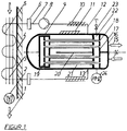
- FIG Figure 1 the heat transfer device designed according to the invention for the provision of cold in refrigerated vehicles, the motor vehicle engine of which is driven by LNG, explained in more detail.
- the cryogenic LNG carried along in a storage tank in the refrigerated vehicle is regasified in the tube bundle heat exchanger (9) provided for this purpose in order to drive the motor vehicle engine as gaseous natural gas (15).
- the heat required here for the evaporation of the LNG is transferred by the heat-emitting material flow of a liquid intermediate medium (5), which in a hermetically closed heat transfer circuit using flexible hose lines (7) and a circulation pump (8) at the inlet and outlet (12, 13 ) of the intermediate medium (5) is guided into or out of the jacket space in forced circulation and in turn draws the heat with a finned tube heat exchanger (3) from the cooling air (1) circulated in the transport space of the refrigerated vehicle with a fan (2) as cooling capacity.
- the LNG evaporator is designed as a tube bundle heat exchanger (9) with a floating head and two jacket paths, so that the large temporal and local temperature changes that occur during operation do not cause any uncontrollable mechanical stresses.
- the cryogenic LNG fed in at the LNG inlet (14) enters via the heat exchanger hood (16) and is distributed over a tube sheet (17) to the heat transfer tubes (18) carrying the LNG, flows to the deflector hood (19) in the floating head of the tube bundle heat exchanger (9) , is deflected and flows, again guided in heat transfer tubes (18), back to the tube sheet (17), from there to the upper part of the heat exchanger hood (16), which is divided by a partition, and finally partially or completely via the outlet nozzle (15) regasified, directly or via an additional heat exchanger operated with engine waste heat, to reach the internal combustion engine of the refrigerated vehicle.
- All LNG-carrying heat transfer pipes (18) of the tube bundle heat exchanger (9) are surrounded by coaxially running protective pipes (21) which are supported by additional tube sheets provided for this purpose, so that the space between the LNG-carrying heat transfer pipes (18) and the protective pipes (21), as well as the spaces between the tube sheets at the ends, filled with a dry gas (22) as a protective gas, act as a thermal resistance that is superimposed on the usual transport resistance of the heat transfer through a simple tube wall.
- the thermal resistance which is specifically increased and opposes the heat transport from the intermediate medium (5) to the LNG, results in a significantly increased driving temperature difference, which means that the surface temperature of the protective tubes (21) wetted by the intermediate medium (5) is significantly higher than that of the -161 ° C cold LNG. Under this condition, i.e. with a corresponding choice of the usually very thin layer thickness of the dry protective gas (22), for example nitrogen or air, intermediate media (5) are available that neither freeze nor become unpumpable due to too high a viscosity
- Therminol D12 is an advantageous solution. It is a synthetic heat transfer fluid based on aliphatic hydrocarbons which, as a heat transfer fluid, can be pumped down to -85 ° C, which is harmless to the environment in the event of a leak and which is approved for occasional unintentional contact with food.
- the intermediate medium (5) enters the shell of the tube bundle heat exchanger (9), which is divided by a partition plate (20), via the nozzle at the inlet (12) and flows over the resulting two jacket paths in countercurrent to the LNG to the nozzle at the outlet (13).
- the liquid intermediate medium (5) transfers the cooling power in the transport space of the refrigerated vehicle, i.e. it absorbs the heat to be transported to the LNG from the cold room air (1).
- a finned tube heat exchanger (3) charged on the inside with the liquid intermediate medium (5) and on the outside with the cooling chamber air (1) conveyed by a fan (2) is used.
- the heat transfer on the outside can be realized so favorably through high ribs and the high flow speed of the cold room air (1) and the heat transfer inside due to the high flow speed of the intermediate medium (5) that the thermal resistance of the heat transfer is minimized and the temperature of the intermediate medium is maximized as a result (5) results in a reduced viscosity and thus in a correspondingly low drive power of the circulating pump (8) ensuring the forced circulation.
- the environmental friendliness of the intermediate medium (5) allows the circuit, which is guided in insulated, partially flexible hose lines (7), to be opened with the aid of quick-release couplings (6) that shut off on both sides, for example in order to separate the trailer of a semitrailer from the tractor.
Landscapes
- Engineering & Computer Science (AREA)
- Mechanical Engineering (AREA)
- Physics & Mathematics (AREA)
- Thermal Sciences (AREA)
- General Engineering & Computer Science (AREA)
- Filling Or Discharging Of Gas Storage Vessels (AREA)
Description
- Die Erfindung betrifft die Kältebereitstellung für Kühlfahrzeuge, die tiefkaltes verflüssigtes Erdgas LNG (liquified natural gas) als Antriebsenergie nutzen.
- Tiefkaltes verflüssigtes Erdgas, das für den Antrieb von Kraftfahrzeugmotoren eingesetzt wird, verdampft man zum Zwecke der Regasifizierung üblicherweise mit Hilfe von Umgebungsluft und/oder Motorabwärme. Die dabei frei werdende energetisch wertvolle Kälteleistung bleibt vielfach ungenutzt, was aber nicht zwangsläufig so sein muss. Vielmehr sollte diese zurückgewonnen und dem Kühlfahrzeug als Transportkälte zur Verfügung gestellt werden.
- Der Stand der Technik hält dazu folgende, in Patentschriften dokumentierte technische Lösungen bereit.
- In den Druckschriften
DE 195 31 122 undEP 0 788 908 wird eine Kühleinrichtung beschrieben, die den Transportraum eines Kühlfahrzeuges kühlt, dessen Kraftfahrzeugmotor mit regasifizierten LNG betrieben wird. Das in einem kälteisolierten Tank mitgeführte, tiefkalte LNG wird über ein hermetisch geschlossenes System in den Transportraum gepumpt und dort in einem Wärmeübertrager durch Wärmeaufnahme aus der umgewälzten Transportraumluft verdampft. Parallel zu diesem Wärmeübertrager ist zusätzlich ein Latentkältespeicher geschaltet, der aus dem Speichermaterial ebenfalls Wärme an das zu verdampfende, hermetisch abgeschlossene LNG abgibt. Das verdampfte LNG strömt schließlich als gasförmiger Brennstoff zum Motor. - Ist der LNG- Fluss bei Motorstillstand unterbrochen, so kann die Kühlung des Transportraumes mit Hilfe des Kältespeichers aufrecht erhalten werden, indem die umgewälzte Raumluft die Speichermasse erwärmt. Dargestellt wird in der Druckschrift ein Sattelzug mit einer Sattelzugmaschine, die den LNG-Tank enthält, und mit einem Sattelauflieger, der den Transportraum mit dem Luftkühler und dem Kältespeicher enthält. Die flüssiges LNG zuführende Leitung und die verdampftes LNG abführende Leitung, und damit auch die Sattelzugmaschine und der Sattelauflieger, können mit Hilfe von Kupplungen unter herrschendem Betriebsdruck leckagefrei getrennt werden. Bei dem dann unterbrochenen LNG- Fluss kann der Kältespeicher die Kühlung fortsetzen. Die vorgeschlagene Kühltechnik hat den Vorteil der sehr einfachen Gestaltung. Dem steht jedoch ein wesentlicher Nachteil gegenüber, nämlich dass das gesamte aus der Pumpe, den Leitungen, den Kupplungen und den Wärmeübertragern bestehende System der Gefahr ausgesetzt ist, dass die mit der tiefen, bis -161 °C reichenden Temperatur des LNG einhergehende verringerte Materialbelastbarkeit eine Undichtigkeit verursacht, die dazu führt, dass brennbares Erdgas in den Transportraum und in die Umgebung des Transportfahrzeuges gelangt.
- In der
DE 10 2010 020 476 ist ebenfalls ein mit tiefkaltem LNG angetriebenes Kühlfahrzeuge beschrieben, bei dem parallel zum LNG- Tank unter Inkaufnahme eines beachtliche Kostenaufwandes ein zusätzlicher Tank, der tiefkalten verflüssigten Stickstoff enthält, mitgeführt ist. Dessen Regasifizierung macht in einem dafür vorgesehenen Wärmeübertrager wertvolle Kälteleistung für das im Transportraum gelagerte Kühlgut verfügbar, und zwar sowohl während des Fahrbetriebes als auch während des Stillstandes bei abgeschaltetem Motor, wobei der entstehende gasförmige Stickstoff gefahrlos an die Umgebung abgeführt wird. Die parallele oder alternative Nutzung der durch die Regasifizierung des tiefkalten LNG freigesetzten Kälteleistung erfolgt beim Betrieb des Motors unter dem vorbeschriebenen gewichtigen Gefahrenpotential des brennbaren Erdgases. - Schließlich wird für Kühlfahrzeuge, die mit tiefkaltem LNG betrieben werden, in den Druckschriften
WO 2011/141287 undUS 2013/0055728 , welche den Oberbegriff des Anspruchs 1 zeigt, eine technische Lösung vorgeschlagen, die zur Rückgewinnung der Kälteleistung mit einem flüssigen, nichtbrennbaren Zwischenmedium arbeitet und so die vom Erdgas ausgehende Gefahr im Bereich des Transportraumes ausschließt. Dargestellt ist ein Sattelzug mit Zugmaschine und Auflieger, in dem sich wie üblich der zu kühlende Transportraum befindet. In diesem wird die zum Zwecke der Kühlung aus umgewälzter Luft abzuführende Wärme in einem Wärmeübertrager an das Zwischenmedium übertragen. Dieses wird mit Hilfe einer Pumpe in einem geschlossenen Wärmeübertragungskreislauf geführt, der aber mit Hilfe von Kupplungen und teilweise flexiblen Leitungen trennbar ist. Das Zwischenmedium transportiert dabei die aufgenommene Wärme zu einem zweiten, auf der Zugmaschine nahe dem LNG- Speicher und dem Verbrennungsmotor platzierten Wärmübertrager, um sie hier an das mit einer Pumpe zugeführte LNG zu übertragen. Was das Gefährdungspotential der durch die tiefe Temperatur bedingten Materialbelastung einerseits und des brennbaren Erdgases andererseits betrifft, so kann die kompakte, sich mit kurzen Leitungswegen begnügende Anordnung der von LNG beaufschlagten Komponenten auf der Zugmaschine als vorteilhaft angeführt werden. Einen wesentlichen Nachteil weist jedoch das vorgeschlagene Verfahren der Übertragung der Wärme an das LNG auf. Es erfolgt rekuperativ über eine das Zwischenmedium und das LNG trennende Wand. Deren Oberflächentemperatur auf der vom Zwischenmedium beaufschlagten Seite unterscheidet sich wegen des sehr geringen Transportwiderstandes der Wärmeleitung durch die dünne Wand einerseits und des Wärmeübergangs an das verdampfenden LNG andererseits nur sehr geringfügig von der Temperatur des LNG. Das Zwischenmedium muss deshalb so beschaffen sein, das es bis hinab zur Temperatur des LNG, also bis -161 °C, nicht gefriert und fließbar ist. Ein derartiges flüssiges Zwischenmedium, von dem zusätzlich noch zu fordern ist, dass es im Falle einer Leckage für die Umwelt, insbesondere für das im Transportraum gelagerte Kühlgut, unschädlich ist, steht nur äußerst begrenzt und dann auch nur sehr kostenaufwendig zur Verfügung. - Zudem erfordert dessen Förderung zum Wärmeübertrager des Transportraumes wegen der tiefen Temperatur und der durch sie bewirkten hohen Viskosität des Zwischenmediums eine hohe Pumpleistung. Die vorgeschlagene Technik ist somit ebenfalls nicht zufriedenstellend.
- Aus dem vorbeschriebenen Stand der Technik, insbesondere aus dessen Nachteilen, leitet sich die erfinderische Aufgabenstellung ab.
- Diese besteht im Wesentlichen in der Entwicklung einer Wärmeübertragungseinrichtung zur Bereitstellung von Transportkälte für Kühlfahrzeuge, die mit tiefkaltem verflüssigtem Erdgas angetrieben werden. Dabei soll dem Kühlraum und dem darin befindlichen Kühlgut durch Luftumwälzung Wärme entzogen und nachfolgend an das zu verdampfende LNG übertragen werden, was allerdings voraussetzt, dass das sehr tiefe Temperaturniveau des LNG, das bis -161 °C betragen kann, sicher beherrscht wird. Insbesondere ist die Gefahr abzuwenden, dass in einem Schadensfall Erdgas NG (natural gas) in den Kühlraum des Kühlfahrzeuges und/oder in einen geschlossenen Raum, in dem das Kühlfahrzeug eventuell abgestellt ist, eintritt. Befindet sich der Kühlraum im Sattelauflieger eines Sattelzuges, so ist zusätzlich zu berücksichtigen, dass sich die Sattelzugmaschine, in der sich der LNG- Tank befindet, vom Sattelauflieger einfach trennen lässt.
- Zur Lösung dieser Aufgabenstellungen sind geeignete technische Mittel anzugeben.
- Die Lösung der Aufgabenstellung ist im Patentanspruch 1 angegeben.
- Die untergeordneten Ansprüche enthalten zweckmäßige Ausgestaltungen.
- Die Erfindung macht sich den Umstand zunutze, dass die Kühlluft im Transportraum des Kühlfahrzeuges nur bis tiefstens -30 °C abzukühlen ist, dass also für den Wärmetransport zum LNG eine sehr hohe treibende Temperaturdifferenz zur Verfügung steht, die es zulässt, die Wärmeübertragung über ein flüssiges Zwischenmedium zu führen, um sich so gegen das dem tiefen Temperaturniveau des LNG anzulastende Gefährdungspotential, das heißt gegen die Verringerung der Materialbelastbarkeit und gegen die mögliche Leckage brennbaren Gases, abzusichern.
- Zu diesem Zweck wird der thermische Widerstand Rth = ΔT / Q, das heißt, der Quotient aus der treibenden, am Widerstand Rth abfallenden Temperaturdifferenz ΔT und der zu übertragenden Wärmeleistung Q des rekuperativen Wärmeübertragers, in welchem die Verdampfung des LNG erfolgt, gezielt so erhöht, dass die Temperatur der Wand, die den wärmeabgebenden vom wärmeaufnehmenden Stoffstrom trennt, auf der dem LNG abgewandten Oberfläche so hoch ist, dass das sie benetzende Zwischenmedium nicht gefriert und sicher fließfähig ist. Wird die zulässige Abkühlung des Zwischenmediums nicht zu tief gefordert, zum Beispiel nur bis -85 °C, so sind geeignete Wärmeträger sehr gut verfügbar.
- Das flüssige Zwischenmedium, von einer Umwälzpumpe im geschlossenen Wärmeträgerkreislauf gefördert, ermöglicht trotz strikter räumlicher Trennung die Wirkverbindung zwischen dem Luftkühler im Transportraum und dem LNG- Verdampfer und damit die kompakt zusammenfassende, einfach abzusichernde Anordnung der durch tiefkaltes LNG beaufschlagten Komponenten LNG- Speicher, LNG- Pumpe und LNG- Wärmeübertrager, zum Beispiel auf der Zugmaschine eines Sattelzuges, und bietet gleichzeitig einen kurzen Leitungsweg für das durch Regasifizierung produzierte brennbare Erdgas zum Verbrennungsmotor. Im Übrigen gestattet die Umweltfreundlichkeit des Zwischenmediums, dass der in gedämmten teilweise flexiblen Leitungen geführte Kreislauf mit Hilfe beidseitig absperrender Schnellverschlusskupplungen geöffnet werden kann, um beispielsweise den Auflieger eines Sattelzuges von der Zugmaschine zu trennen.
- Erfindungsgemäß erfolgt die Wärmeübertragung an das LNG in einem aus kaltzähem Werkstoff gefertigten Rohrbündelwärmeübertrager, der das zu verdampfende LNG in den Rohren und das wärmeabgebende Zwischenmedium im Mantelraum führt und der so gestaltet ist, dass die in Folge der im Betrieb auftretenden großen zeitlichen und örtlichen Temperaturänderungen keine unbeherrschbaren mechanischen Spannungen verursachen. Für die Erfindung vorgeschlagen ist ein Rohrbündelwärmeübertrager mit Schwimmkopf und zwei Mantelwegen.
- Die Erfindung schlägt vor, in den Rohrbündelwärmeübertrager einen zusätzlichen, den üblich vorhandenen Widerstand gezielt erweiternden thermischen Widerstand einzufügen. Dieser wird erfindungsgemäß durch Anordnung koaxial verlaufender Schutzrohre erreicht, welche die LNG führenden Wärmeübertragungsrohre so umhüllen, dass ein hermetisch geschlossener mit einem trockenen Gas, beispielsweise Stickstoff oder Luft, zu füllender Zwischenraum entsteht, dessen geringe Schichtdicke zwischen den Rohren so auszulegen ist, dass sich auf der dem Zwischenmedium zugewandten Oberfläche des Schutzrohres die gewünschte ausreichend hohe Temperatur einstellt.
- Als weitere sicherheitstechnische Maßnahme wird vorgeschlagen, den Druck des hermetisch zwischen den koaxialen Rohren und in den Freiräumen zwischen den Rohrplatten eingeschlossenen trockenen Gases deutlich niedriger zu wählen als den minimalen LNG- Druck, so dass der bei einer Undichtigkeit infolge eindringenden Erdgases auftretende Druckanstieg den dafür vorgesehenen Sicherheitsdruckschalter und über diesen die Sperrung der LNG- Zufuhr auslöst. Der Nachteil, dass wegen des vergrößerten thermischen Widerstandes im Rohrbündelwärmeübertrager für die Sicherstellung der erforderlichen Wärmedurchgangsleistung die Wärmeübertragungsfläche erhöht werden muss, wird durch die nun gegebene Möglichkeit kompensiert, ein gleichermaßen wirksames wie kostengünstiges flüssiges Zwischenmedium zu wählen. Diesbezüglich ist Therminol D12 eine vorteilhafte Lösung. Es handelt sich um eine synthetische Wärmeträgerflüssigkeit auf der Basis aliphatischer Kohlenwasserstoffe, die als Wärmeträgerflüssigkeit bis hinab zu -85 °C nicht gefriert und pumpfähig ist, die bei einer Leckage im Störfall für die Umwelt unschädlich ist und die für gelegentliche unbeabsichtigte Kontakte mit Lebensmitteln zugelassen ist.
- Das flüssige Zwischenmedium überträgt im Transportraum des Kühlfahrzeuges die Kälteleistung, das heißt, es nimmt aus der zu kühlenden Luft die zum LNG zu transportierende Wärme auf. Hierfür ist ein innen mit dem flüssigen Zwischenmedium und außen mit der von einem Ventilator geförderten Kühlraumluft beaufschlagter Rippenrohrwärmeübertrager eingesetzt.
- Der Wärmeübergang außen ist durch hohe Rippen und durch die hohe Strömungsgeschwindigkeit der Luft und der Wärmeübergang innen ist durch die hohe Strömungsgeschwindigkeit des Zwischenmediums so günstig realisierbar, dass der thermische Widerstand des Wärmedurchgangs minimiert ist und die dadurch maximierte Temperatur des Zwischenmediums in eine reduzierte Viskosität und damit in eine entsprechend geringe Antriebsleistung der den Zwangsumlauf sicherstellenden Umwälzpumpe resultiert.
- Im nachstehenden Ausführungsbeispiel wird die Erfindung an Hand einer schematischen Darstellung in
Figur 1 der erfindungsgemäß gestalteten Wärmeübertragungseinrichtung für die Kältebereitstellung in Kühlfahrzeugen, deren Kraftfahrzeugmotor mit LNG angetrieben wird, näher erläutert. - Alle durch das vom LNG geprägten mit tiefem Temperaturniveau belasteten Bauteile bestehen aus kaltzähem Material. Alle auf tiefen Temperaturen befindlichen Bauteile sind durch eine Dämmung vor unerwünschtem Wärmeeinfall geschützt.
- Das im Kühlfahrzeug in einem Speicher mitgeführte tiefkalte LNG wird in dem dafür vorgesehenen Rohrbündel- Wärmeübertrager (9) regasifiziert, um als gasförmiges Erdgas (15) den Kraftfahrzeugmotor anzutreiben. Die hier für die Verdampfung des LNG benötigte Wärme wird durch den wärmeabgebenden Stoffstrom eines flüssigen Zwischenmediums (5) übertragen, das in einem hermetisch geschlossenen Wärmeübertragungskreislauf unter Nutzung flexibler Schlauchleitungen (7) und einer Umwälzpumpe (8) bei Ein- und Austritt (12, 13) des Zwischenmediums (5) in bzw. aus dem Mantelraum im Zwangsumlauf geführt ist und seinerseits die Wärme mit einem Rippenrohr- Wärmeübertrager (3) aus der im Transportraum des Kühlfahrzeuges mit einem Ventilator (2) umgewälzten Kühlluft (1) als Kälteleistung bezieht.
- Der LNG- Verdampfer ist als Rohrbündelwärmeübertrager (9) mit Schwimmkopf und zwei Mantelwegen ausgeführt, so dass die in Folge der im Betrieb auftretenden großen zeitlichen und örtlichen Temperaturänderungen keine unbeherrschbaren mechanischen Spannungen verursachen.
- Das am LNG- Eintritt (14) zugeführte tiefkalte LNG tritt über die Wärmeübertragerhaube (16) ein und wird über einen Rohrboden (17) auf die LNG führenden Wärmeübertragungsrohre (18) verteilt, fließt zur Umlenkhaube (19) im Schwimmkopf des Rohrbündelwärmeübertragers (9), wird umgelenkt und fließt, wiederum in Wärmeübertragungsrohren (18) geführt, zum Rohrboden (17) zurück, um von dort in den oberen Teil der durch eine Trennwand geteilten Wärmeübertragerhaube (16) zu gelangen und schließlich über den Austrittsstutzen (15) teilweise oder vollständig regasifiziert, direkt oder über einen zusätzlichen mit Motorabwärme betriebenen Wärmeübertrager, den Verbrennungsmotor des Kühlfahrzeuges zu erreichen.
- Alle LNG führenden Wärmeübertragungsrohre (18) des Rohrbündelwärmeübertragers (9) sind von koaxial verlaufenden Schutzrohren (21) umgeben, die von dafür vorgesehenen zusätzlichen Rohrböden getragen werden, so dass der Zwischenraum zwischen den LNG führenden Wärmeübertragungsrohren (18) und den Schutzrohren (21), wie auch die Räume zwischen den Rohrböden an den Enden, mit einem trockenen Gas (22) als Schutzgas gefüllt, als thermischer Widerstand wirken, der sich dem üblichen Transportwiderstand des Wärmedurchgangs durch eine einfache Rohrwand überlagert. Aus dem damit gezielt vergrößerten, dem Wärmetransport vom Zwischenmedium (5) zum LNG entgegen stehenden thermischen Widerstand resultiert eine deutlich erhöhte treibende Temperaturdifferenz, was zur Folge hat, dass die Oberflächentemperatur der vom Zwischenmedium (5) benetzten Schutzrohre (21) deutlich höher ist als diejenige des bis -161 °C kalten LNG. Unter dieser Voraussetzung, das heißt bei entsprechender Wahl der in der Regel sehr dünnen Schichtdicke des trockenen Schutzgases (22), beispielsweise Stickstoff oder Luft, stehen Zwischenmedien (5) zur Verfügung, die weder gefrieren, noch wegen zu hoher Viskosität unpumpbar werden.
- Der Nachteil, dass wegen des vergrößerten thermischen Widerstandes im LNG- Verdampfer für die Sicherstellung des erforderlichen Wärmedurchganges die Wärmeübertragungsfläche erhöht werden muss, wird durch die nun gegebene Möglichkeit kompensiert, ein gleichermaßen wirksames wie kostengünstiges flüssiges Zwischenmedium (5) zu wählen. Diesbezüglich ist Therminol D12 eine vorteilhafte Lösung. Es handelt sich um eine synthetische Wärmeträgerflüssigkeit auf der Basis aliphatischer Kohlenwasserstoffe, die als Wärmeträgerflüssigkeit bis hinab zu -85 °C pumpfähig ist, die bei einer Leckage im Störfall für die Umwelt unschädlich ist und die für gelegentliche unbeabsichtigte Kontakte mit Lebensmitteln zugelassen ist. Das Zwischenmedium (5) tritt über den Stutzen am Eintritt (12) in den durch ein Trennblech (20) geteilten Mantelraum des Rohrbündelwärmeübertragers (9) ein und strömt über die sich ergebenden zwei Mantelwege im Gegenstrom zum LNG zum Stutzen am Austritt (13).
- Als weitere sicherheitstechnische Maßnahme wird vorgeschlagen, den Druck des hermetisch zwischen den koaxialen Rohren und in den Freiräumen zwischen den Rohrplatten eingeschlossenen trockenen Gases (22) deutlich niedriger zu wählen als den minimalen LNG- Druck, so dass der bei einer Undichtigkeit infolge eindringenden Erdgases auftretende Druckanstieg den dafür vorgesehenen Sicherheitsdruckschalter (24) und über diesen die Sperrung der LNG- Zufuhr auslöst.
- Das flüssige Zwischenmedium (5) überträgt im Transportraum des Kühlfahrzeuges die Kälteleistung, das heißt, es nimmt aus der Kühlraumluft (1) die zum LNG zu transportierende Wärme auf. Hierfür wird ein innen mit dem flüssigen Zwischenmedium (5) und außen mit der von einem Ventilator (2) geförderten Kühlraumluft (1) beaufschlagter Rippenrohrwärmeübertrager (3) eingesetzt.
- Der Wärmeübergang außen ist durch hohe Rippen und durch die hohe Strömungsgeschwindigkeit der Kühlraumluft (1) und der Wärmeübergang innen ist durch die hohe Strömungsgeschwindigkeit des Zwischenmediums (5) so günstig realisierbar, dass der thermische Widerstand des Wärmedurchgangs minimiert ist und die dadurch maximierte Temperatur des Zwischenmediums (5) in eine reduzierte Viskosität und damit in eine entsprechend geringe Antriebsleistung der den Zwangsumlauf sicherstellenden Umwälzpumpe (8) resultiert.
- Im Übrigen gestattet die Umweltfreundlichkeit des Zwischenmediums (5), dass der in gedämmten, teilweise flexiblen Schlauchleitungen (7) geführte Kreislauf mit Hilfe beidseitig absperrender Schnellverschlusskupplungen (6) geöffnet werden kann, um beispielsweise den Auflieger eines Sattelzuges von der Zugmaschine zu trennen.
-
- LNG
- Verflüssigtes Erdgas (liquified natural gas)
- NG
- Regasifiziertes Erdgas
- Rth
- Thermischer Widerstand
- Q
- Wärmeleistung
- ΔT
- Temperaturdifferenz
- PHZ
- Druck, oberer Grenzwert, Schutz durch Auslösung bzw. sicherheitsrelevante Schaltfunktion
- 1
- Kühlraumluft
- 2
- Ventilator
- 3
- Rippenrohrwärmeübertrager
- 4
- Gedämmte Kühlraumwand
- 5
- Wärmeübertragendes Zwischenmedium
- 6
- Beidseitig absperrende Schnellverschlusskupplung
- 7
- Flexible Leitung
- 8
- Umwälzpumpe
- 9
- Rohrbündelwärmeübertrager (mit Schwimmkopf und zwei Mantelwege)
- 10
- Dämmung
- 11
- Dämmung
- 12
- Eintritt des Zwischenmediums in den Mantelraum
- 13
- Austritt des Zwischenmediums aus dem Mantelraum
- 14
- LNG- Eintritt
- 15
- Austrittsstutzen für verdampftes LNG
- 16
- Wärmeübertragerhaube mit Trennwand und LNG- Stutzen
- 17
- Rohrboden
- 18
- LNG führendes Wärmeübertragungsrohr
- 19
- Umlenkhaube (im Schwimmkopf des Rohrbündelwärmeübertragers)
- 20
- Trennblech (im Mantelraum des Rohrbündelwärmeübertragers)
- 21
- Schutzrohr (koaxial zum LNG führenden Rohr)
- 22
- Trockenes Gas (als hermetisch eingeschlossenes Schutzgas)
- 23
- Serviceventil
- 24
- Sicherheitsdruckschalter (Schließt bei steigendem Druck die LNG- Zufuhr.)
Claims (4)
- Wärmeübertragungseinrichtung für die Kältebereitstellung in Kühlfahrzeugen durch Verdampfung von verflüssigtem Erdgas (LNG), wobei das regasifizierte Erdgas (NG) einerseits zum Antrieb des Motors des Kühlfahrzeugs vorgesehen ist und die verfügbare Kälteleistung andererseits zur Kühlung des mit dem Kühlfahrzeug zu transportierenden Kühlgutes nutzbar ist, indem ein im Kühlraum angeordneter erster, als Rippenrohrwärmeübertrager ausgeführter Wärmeübertrager (3) mit einem außerhalb des Kühlraumes befindlichen zweiten Wärmeübertrager (9) als LNG- Verdampfer unter strikter räumlicher Trennung in Wirkverbindung steht, wodurch dem Kühlraum Wärme entziehbar und mittels ventilatorgeförderter Kühlraumluft (1) und dem ersten Wärmeübertrager (3) Wärme abführbar ist, und zwar unter Nutzung eines im geschlossenen Kreislauf in Zwangsumlauf zwischen dem ersten Wärmeübertrager (3) und dem zweiten Wärmeübertrager (9) geführten flüssigen Zwischenmediums (5), das als synthetische Wärmeträgerflüssigkeit auf Basis aliphatischer Kohlenwasserstoffe bis hinab zu - 85 °C nicht gefriert und pumpfähig ist, bei einer Leckage im Störfall für die Umwelt unschädlich ist und für gelegentliche unbeabsichtigte Kontakte mit Lebensmitteln zugelassen ist, dadurch gekennzeichnet, dass für die Verdampfung des über den LNG- Eintritt (14) zuströmenden LNG´s ein aus kaltzähem Werkstoff gefertigter zweiter Wärmeübertrager (9) eingesetzt ist, der das zu verdampfende LNG in den Wärmeübertragungsrohren (18) und das wärmeübertragende Zwischenmedium (5) im Mantelraum vom Eintritt (12) zum Austritt (13) führt und als Rohrbündelwärmeübertrager (9) mit Schwimmkopf und zwei Mantelwegen ausgeführt ist, wodurch die in Folge der im Betrieb auftretenden großen zeitlichen und örtlichen Temperaturänderungen ausschließlich beherrschbare mechanische Spannungen verursachen und wobei koaxial angeordnete Schutzrohre (21) die LNG führenden Wärmeübertragungsrohre (18) so umhüllen, dass ein hermetisch abgeschlossener, mit einem trockenen Gas (22) füllbarer Zwischenraum gebildet ist, dessen geringe Schichtdicke zwischen den Rohren (18 und 21) so ausgelegt ist, dass hier der thermische Widerstand (Rth) zu einem Temperaturabfall führt, der ein Gefrieren des Zwischenmediums (5) an der Oberfläche des Schutzrohres (21) ausschließt.
- Wärmeübertragungseinrichtung nach Anspruch 1, dadurch gekennzeichnet, dass der Druck des hermetisch eingeschlossenen trockenen Gases (22) deutlich niedriger gewählt ist als der minimale LNG- Druck, wodurch sichergestellt ist, dass der bei einer Undichtigkeit infolge eindringenden Erdgases auftretende Druckanstieg den dafür vorgesehenen Sicherheitsdruckschalter (24) und über diesen die Sperrung der LNG- Zufuhr auslöst.
- Wärmeübertragungseinrichtung nach Anspruch 1, dadurch gekennzeichnet, dass das Zwischenmedium (5) von einer Umwälzpumpe (8) gefördert wird und die Wärme aus der von einem Ventilator (2) geförderten Kühlraumluft (1) an die Rippen des innen mit Zwischenmedium (5) beaufschlagten Rippenrohrwärmeübertragers (3) übertragbar ist, an dem der Wärmeübergang außen durch hohe Rippen und durch eine hohe Strömungsgeschwindigkeit der Kühlraumluft (1) und der Wärmeübergang innen durch eine hohe Strömungsgeschwindigkeit des Zwischenmediums (5) so günstig realisierbar ist, dass der thermische Widerstand (Rth = ΔT / Q), das heißt, der Quotient aus der treibenden, am Widerstand abfallenden Temperaturdifferenz (ΔT) und der Wärmeleistung (Q) des Wärmedurchgangs minimiert ist und die dadurch maximierte Temperatur des Zwischenmediums (5) in eine reduzierte Viskosität und damit in eine entsprechend geringe Antriebsleistung der Umwälzpumpe (8) resultiert.
- Wärmeübertragungseinrichtung nach Anspruch 1, dadurch gekennzeichnet, dass das die Wärme aus dem Rippenrohrwärmeübertrager (3) zum Rohrbündelwärmeübertrager (9) transportierende Zwischenmedium (5) in mit Dämmungen (10) versehenen und zumindest teilweise flexiblen Leitungen (7) geführt ist, die mit Hilfe beidseitig absperrender Schnellverschlusskupplungen (6) trennbar sind.
Priority Applications (1)
| Application Number | Priority Date | Filing Date | Title |
|---|---|---|---|
| PL18836452T PL3732069T3 (pl) | 2017-12-29 | 2018-12-05 | Urządzenie do przenoszenia ciepła do dostarczania zimna w pojazdach-chłodniach, których silnik pojazdu mechanicznego jest napędzany lng |
Applications Claiming Priority (2)
| Application Number | Priority Date | Filing Date | Title |
|---|---|---|---|
| DE102017012125.7A DE102017012125A1 (de) | 2017-12-29 | 2017-12-29 | Wärmeübertragungseinrichtung für die Kältebereitstellung in Kühlfahrzeugen, deren Kraftfahrzeugmotor mit LNG angetrieben wird |
| PCT/DE2018/000360 WO2019129320A1 (de) | 2017-12-29 | 2018-12-05 | Wärmeübertragungseinrichtung für die kältebereitstellung in kühlfahrzeugen, deren kraftfahrzeugmotor mit lng angetrieben wird |
Publications (2)
| Publication Number | Publication Date |
|---|---|
| EP3732069A1 EP3732069A1 (de) | 2020-11-04 |
| EP3732069B1 true EP3732069B1 (de) | 2022-01-05 |
Family
ID=65036553
Family Applications (1)
| Application Number | Title | Priority Date | Filing Date |
|---|---|---|---|
| EP18836452.5A Active EP3732069B1 (de) | 2017-12-29 | 2018-12-05 | Wärmeübertragungseinrichtung für die kältebereitstellung in kühlfahrzeugen, deren kraftfahrzeugmotor mit lng angetrieben wird |
Country Status (7)
| Country | Link |
|---|---|
| US (1) | US20210379967A1 (de) |
| EP (1) | EP3732069B1 (de) |
| CN (1) | CN111801231A (de) |
| DE (2) | DE102017012125A1 (de) |
| ES (1) | ES2910116T3 (de) |
| PL (1) | PL3732069T3 (de) |
| WO (1) | WO2019129320A1 (de) |
Families Citing this family (5)
| Publication number | Priority date | Publication date | Assignee | Title |
|---|---|---|---|---|
| EP3798030B1 (de) * | 2019-09-25 | 2022-08-03 | Ningbo Geely Automobile Research & Development Co. Ltd. | Klimaanlage für ein fahrzeug |
| CN114199303A (zh) * | 2021-11-02 | 2022-03-18 | 华能核能技术研究院有限公司 | 一种用于高温气冷堆的一回路湿度测量装置 |
| CN115628118B (zh) * | 2022-08-31 | 2026-02-10 | 西安交通大学 | 一种透平膨胀机自循环干气密封装置 |
| CN118548727B (zh) * | 2024-07-30 | 2024-11-26 | 杭州沈氏节能科技股份有限公司 | 一种防冻换热器 |
| CN119043053B (zh) * | 2024-10-31 | 2025-01-10 | 宝鸡宝色冶金制品有限责任公司 | 一种钛管换热器 |
Family Cites Families (11)
| Publication number | Priority date | Publication date | Assignee | Title |
|---|---|---|---|---|
| GB748264A (en) * | 1951-10-23 | 1956-04-25 | Foster Wheeler Ltd | Improvements in and relating to heat exchangers |
| DE19531122A1 (de) | 1995-08-24 | 1997-02-27 | Messer Griesheim Gmbh | Fahrzeug |
| JP4291459B2 (ja) * | 1999-06-28 | 2009-07-08 | 大阪瓦斯株式会社 | 熱交換器の徐冷方法及び装置 |
| US6447692B1 (en) * | 2000-08-04 | 2002-09-10 | Hrl Laboratories, Llc | Nanometer sized phase change materials for enhanced heat transfer fluid performance |
| DE102006016558A1 (de) * | 2006-04-07 | 2007-10-11 | Air Liquide Deutschland Gmbh | Verfahren zum Überwachen der Gasdichtheit eines Kühlsystems eines Kühlfahrzeuges und zum Betreiben desselben sowie Kühlsystem für ein Kühlfahrzeug und Kühlfahrzeug |
| DE102006016555A1 (de) * | 2006-04-07 | 2007-10-11 | Air Liquide Deutschland Gmbh | Verfahren und Vorrichtung zum Aufbauen eines Überdrucks in einem Tank für verflüssigtes Gas eines Kühlfahrzeugs sowie Kühlsystem für ein Kühlfahrzeug und Kühlfahrzeug |
| DE102010020476B4 (de) | 2010-05-14 | 2023-05-04 | Air Liquide Deutschland Gmbh | Verwendung einer Vorrichtung zum Speichern, Umfüllen und/oder Transportieren von tiefkalt verflüssigtem brennbarem Gas in einem Fahrzeug |
| UA107877C2 (uk) * | 2013-07-24 | 2015-02-25 | Roland Volodymyrovych Havrylov | Транспортний засіб для транспортування термонеcтійких продуктів та спосіб транспортування термонестійких продуктів |
| WO2016130537A1 (en) * | 2015-02-12 | 2016-08-18 | Carrier Corporation | Chiller for refrigeration system |
| DE102016006121A1 (de) * | 2015-12-28 | 2017-06-29 | Eco ice Kälte GmbH | Verfahren und Wärmeaustauscher zur Rückgewinnung von Kälte bei der Regasifizierung tiefkalter Flüssigkeiten |
| EP3900971B1 (de) * | 2020-04-20 | 2023-04-19 | Carrier Corporation | System zur lagerung und abgabe von erdgas für ein gekühltes frachtfahrzeug |
-
2017
- 2017-12-29 DE DE102017012125.7A patent/DE102017012125A1/de not_active Withdrawn
-
2018
- 2018-12-05 US US16/956,851 patent/US20210379967A1/en not_active Abandoned
- 2018-12-05 PL PL18836452T patent/PL3732069T3/pl unknown
- 2018-12-05 CN CN201880090489.2A patent/CN111801231A/zh active Pending
- 2018-12-05 WO PCT/DE2018/000360 patent/WO2019129320A1/de not_active Ceased
- 2018-12-05 ES ES18836452T patent/ES2910116T3/es active Active
- 2018-12-05 EP EP18836452.5A patent/EP3732069B1/de active Active
- 2018-12-05 DE DE112018006645.2T patent/DE112018006645A5/de not_active Withdrawn
Also Published As
| Publication number | Publication date |
|---|---|
| EP3732069A1 (de) | 2020-11-04 |
| US20210379967A1 (en) | 2021-12-09 |
| ES2910116T3 (es) | 2022-05-11 |
| CN111801231A (zh) | 2020-10-20 |
| WO2019129320A1 (de) | 2019-07-04 |
| DE102017012125A1 (de) | 2019-07-04 |
| DE112018006645A5 (de) | 2020-11-19 |
| PL3732069T3 (pl) | 2022-07-04 |
Similar Documents
| Publication | Publication Date | Title |
|---|---|---|
| WO2019129320A1 (de) | Wärmeübertragungseinrichtung für die kältebereitstellung in kühlfahrzeugen, deren kraftfahrzeugmotor mit lng angetrieben wird | |
| DE2743918C3 (de) | Offene Gasturbinenanlage, mit der ein Dampfkreislauf kombiniert ist | |
| DE69132162T2 (de) | Enthalpiesteuerung für ein co2-kältesystem | |
| DE102010020476B4 (de) | Verwendung einer Vorrichtung zum Speichern, Umfüllen und/oder Transportieren von tiefkalt verflüssigtem brennbarem Gas in einem Fahrzeug | |
| EP0437768B1 (de) | Auslaufsicherer Wasserstoff/Luft-Wärmetauscher | |
| EP0874188B2 (de) | Verfahren zum Aufbereiten von tiefgekühltem Flüssiggas | |
| EP3676529B1 (de) | Verfahren zum befüllen eines mobilen kältemitteltanks mit einem kryogenen kältemittel | |
| DE10333779A1 (de) | Verfahren und Vorrichtung zum Bewegen von Luft durch einen Wärmetauscher | |
| DE2942565A1 (de) | Flammenloser verdampfer | |
| EP0202344B1 (de) | Vorrichtung zur Wärmeentziehung aus den Auspuffgasen eines Verbrennungsmotors | |
| EP1792071A1 (de) | Wärmeübertrager für wasserstoffbetriebene kraftstoffversorgungsanlagen | |
| DE2149819A1 (de) | Kaeltemaschine fuer die kuehlung des innenraumes von kraftfahrzeugen | |
| DE10060786A1 (de) | Verfahren und Vorrichtung zur Bereitstellung eines zündfähigen Arbeitsgases aus einem Kryokraftstoff | |
| DE4413030C1 (de) | Sorptionsklimaanlage | |
| DE102004022733A1 (de) | Wärmepumpentyp-Heißwasserversorgungssystem | |
| DE69729288T2 (de) | Gekühlter treibstoff für motoren | |
| DE102023111827A1 (de) | Verfahren zum Entleeren eines Tanks für flüssigen Wasserstoff | |
| DE10202165B4 (de) | Kraftfahrzeug mit einem Kryotank | |
| DE102015112704B4 (de) | Dampfkreisprozess | |
| DE102007052259A1 (de) | Kraftstoffversorgungseinrichtung für ein mit Wasserstoff zu betreibendes Kraftfahrzeug | |
| DE2605272C2 (de) | Kühlvorrichtung | |
| DE1247751B (de) | Gasturbinen-Speicherkraftanlage | |
| DE102012018461A1 (de) | Verfahren zum Befüllen eines Kältemitteltanks eines Kühlfahrzeugs sowie Kühlfahrzeug | |
| DE19705215C1 (de) | Gasturbinenanlage | |
| DE3437750A1 (de) | Hilfseinrichtung |
Legal Events
| Date | Code | Title | Description |
|---|---|---|---|
| STAA | Information on the status of an ep patent application or granted ep patent |
Free format text: STATUS: UNKNOWN |
|
| STAA | Information on the status of an ep patent application or granted ep patent |
Free format text: STATUS: THE INTERNATIONAL PUBLICATION HAS BEEN MADE |
|
| PUAI | Public reference made under article 153(3) epc to a published international application that has entered the european phase |
Free format text: ORIGINAL CODE: 0009012 |
|
| STAA | Information on the status of an ep patent application or granted ep patent |
Free format text: STATUS: REQUEST FOR EXAMINATION WAS MADE |
|
| 17P | Request for examination filed |
Effective date: 20200709 |
|
| AK | Designated contracting states |
Kind code of ref document: A1 Designated state(s): AL AT BE BG CH CY CZ DE DK EE ES FI FR GB GR HR HU IE IS IT LI LT LU LV MC MK MT NL NO PL PT RO RS SE SI SK SM TR |
|
| AX | Request for extension of the european patent |
Extension state: BA ME |
|
| DAV | Request for validation of the european patent (deleted) | ||
| DAX | Request for extension of the european patent (deleted) | ||
| RAP3 | Party data changed (applicant data changed or rights of an application transferred) |
Owner name: REGASCOLD GMBH |
|
| GRAP | Despatch of communication of intention to grant a patent |
Free format text: ORIGINAL CODE: EPIDOSNIGR1 |
|
| STAA | Information on the status of an ep patent application or granted ep patent |
Free format text: STATUS: GRANT OF PATENT IS INTENDED |
|
| RIC1 | Information provided on ipc code assigned before grant |
Ipc: F28F 23/02 20060101ALI20210802BHEP Ipc: F28F 9/02 20060101ALI20210802BHEP Ipc: F28F 1/00 20060101ALI20210802BHEP Ipc: F28D 15/00 20060101ALI20210802BHEP Ipc: F28D 7/16 20060101ALI20210802BHEP Ipc: F17C 9/04 20060101ALI20210802BHEP Ipc: B60H 1/32 20060101ALI20210802BHEP Ipc: B60H 1/00 20060101AFI20210802BHEP |
|
| INTG | Intention to grant announced |
Effective date: 20210907 |
|
| GRAS | Grant fee paid |
Free format text: ORIGINAL CODE: EPIDOSNIGR3 |
|
| GRAA | (expected) grant |
Free format text: ORIGINAL CODE: 0009210 |
|
| STAA | Information on the status of an ep patent application or granted ep patent |
Free format text: STATUS: THE PATENT HAS BEEN GRANTED |
|
| AK | Designated contracting states |
Kind code of ref document: B1 Designated state(s): AL AT BE BG CH CY CZ DE DK EE ES FI FR GB GR HR HU IE IS IT LI LT LU LV MC MK MT NL NO PL PT RO RS SE SI SK SM TR |
|
| REG | Reference to a national code |
Ref country code: GB Ref legal event code: FG4D Free format text: NOT ENGLISH |
|
| REG | Reference to a national code |
Ref country code: CH Ref legal event code: EP |
|
| REG | Reference to a national code |
Ref country code: AT Ref legal event code: REF Ref document number: 1460216 Country of ref document: AT Kind code of ref document: T Effective date: 20220115 |
|
| REG | Reference to a national code |
Ref country code: DE Ref legal event code: R096 Ref document number: 502018008472 Country of ref document: DE |
|
| REG | Reference to a national code |
Ref country code: IE Ref legal event code: FG4D Free format text: LANGUAGE OF EP DOCUMENT: GERMAN |
|
| REG | Reference to a national code |
Ref country code: LT Ref legal event code: MG9D |
|
| REG | Reference to a national code |
Ref country code: NL Ref legal event code: MP Effective date: 20220105 Ref country code: ES Ref legal event code: FG2A Ref document number: 2910116 Country of ref document: ES Kind code of ref document: T3 Effective date: 20220511 |
|
| PG25 | Lapsed in a contracting state [announced via postgrant information from national office to epo] |
Ref country code: NL Free format text: LAPSE BECAUSE OF FAILURE TO SUBMIT A TRANSLATION OF THE DESCRIPTION OR TO PAY THE FEE WITHIN THE PRESCRIBED TIME-LIMIT Effective date: 20220105 |
|
| PG25 | Lapsed in a contracting state [announced via postgrant information from national office to epo] |
Ref country code: SE Free format text: LAPSE BECAUSE OF FAILURE TO SUBMIT A TRANSLATION OF THE DESCRIPTION OR TO PAY THE FEE WITHIN THE PRESCRIBED TIME-LIMIT Effective date: 20220105 Ref country code: RS Free format text: LAPSE BECAUSE OF FAILURE TO SUBMIT A TRANSLATION OF THE DESCRIPTION OR TO PAY THE FEE WITHIN THE PRESCRIBED TIME-LIMIT Effective date: 20220105 Ref country code: PT Free format text: LAPSE BECAUSE OF FAILURE TO SUBMIT A TRANSLATION OF THE DESCRIPTION OR TO PAY THE FEE WITHIN THE PRESCRIBED TIME-LIMIT Effective date: 20220505 Ref country code: NO Free format text: LAPSE BECAUSE OF FAILURE TO SUBMIT A TRANSLATION OF THE DESCRIPTION OR TO PAY THE FEE WITHIN THE PRESCRIBED TIME-LIMIT Effective date: 20220405 Ref country code: LT Free format text: LAPSE BECAUSE OF FAILURE TO SUBMIT A TRANSLATION OF THE DESCRIPTION OR TO PAY THE FEE WITHIN THE PRESCRIBED TIME-LIMIT Effective date: 20220105 Ref country code: HR Free format text: LAPSE BECAUSE OF FAILURE TO SUBMIT A TRANSLATION OF THE DESCRIPTION OR TO PAY THE FEE WITHIN THE PRESCRIBED TIME-LIMIT Effective date: 20220105 Ref country code: BG Free format text: LAPSE BECAUSE OF FAILURE TO SUBMIT A TRANSLATION OF THE DESCRIPTION OR TO PAY THE FEE WITHIN THE PRESCRIBED TIME-LIMIT Effective date: 20220405 |
|
| PG25 | Lapsed in a contracting state [announced via postgrant information from national office to epo] |
Ref country code: LV Free format text: LAPSE BECAUSE OF FAILURE TO SUBMIT A TRANSLATION OF THE DESCRIPTION OR TO PAY THE FEE WITHIN THE PRESCRIBED TIME-LIMIT Effective date: 20220105 Ref country code: GR Free format text: LAPSE BECAUSE OF FAILURE TO SUBMIT A TRANSLATION OF THE DESCRIPTION OR TO PAY THE FEE WITHIN THE PRESCRIBED TIME-LIMIT Effective date: 20220406 Ref country code: FI Free format text: LAPSE BECAUSE OF FAILURE TO SUBMIT A TRANSLATION OF THE DESCRIPTION OR TO PAY THE FEE WITHIN THE PRESCRIBED TIME-LIMIT Effective date: 20220105 |
|
| PG25 | Lapsed in a contracting state [announced via postgrant information from national office to epo] |
Ref country code: IS Free format text: LAPSE BECAUSE OF FAILURE TO SUBMIT A TRANSLATION OF THE DESCRIPTION OR TO PAY THE FEE WITHIN THE PRESCRIBED TIME-LIMIT Effective date: 20220505 |
|
| REG | Reference to a national code |
Ref country code: DE Ref legal event code: R097 Ref document number: 502018008472 Country of ref document: DE |
|
| PG25 | Lapsed in a contracting state [announced via postgrant information from national office to epo] |
Ref country code: SM Free format text: LAPSE BECAUSE OF FAILURE TO SUBMIT A TRANSLATION OF THE DESCRIPTION OR TO PAY THE FEE WITHIN THE PRESCRIBED TIME-LIMIT Effective date: 20220105 Ref country code: SK Free format text: LAPSE BECAUSE OF FAILURE TO SUBMIT A TRANSLATION OF THE DESCRIPTION OR TO PAY THE FEE WITHIN THE PRESCRIBED TIME-LIMIT Effective date: 20220105 Ref country code: RO Free format text: LAPSE BECAUSE OF FAILURE TO SUBMIT A TRANSLATION OF THE DESCRIPTION OR TO PAY THE FEE WITHIN THE PRESCRIBED TIME-LIMIT Effective date: 20220105 Ref country code: EE Free format text: LAPSE BECAUSE OF FAILURE TO SUBMIT A TRANSLATION OF THE DESCRIPTION OR TO PAY THE FEE WITHIN THE PRESCRIBED TIME-LIMIT Effective date: 20220105 Ref country code: DK Free format text: LAPSE BECAUSE OF FAILURE TO SUBMIT A TRANSLATION OF THE DESCRIPTION OR TO PAY THE FEE WITHIN THE PRESCRIBED TIME-LIMIT Effective date: 20220105 Ref country code: CZ Free format text: LAPSE BECAUSE OF FAILURE TO SUBMIT A TRANSLATION OF THE DESCRIPTION OR TO PAY THE FEE WITHIN THE PRESCRIBED TIME-LIMIT Effective date: 20220105 |
|
| PLBE | No opposition filed within time limit |
Free format text: ORIGINAL CODE: 0009261 |
|
| STAA | Information on the status of an ep patent application or granted ep patent |
Free format text: STATUS: NO OPPOSITION FILED WITHIN TIME LIMIT |
|
| PG25 | Lapsed in a contracting state [announced via postgrant information from national office to epo] |
Ref country code: AL Free format text: LAPSE BECAUSE OF FAILURE TO SUBMIT A TRANSLATION OF THE DESCRIPTION OR TO PAY THE FEE WITHIN THE PRESCRIBED TIME-LIMIT Effective date: 20220105 |
|
| 26N | No opposition filed |
Effective date: 20221006 |
|
| PG25 | Lapsed in a contracting state [announced via postgrant information from national office to epo] |
Ref country code: SI Free format text: LAPSE BECAUSE OF FAILURE TO SUBMIT A TRANSLATION OF THE DESCRIPTION OR TO PAY THE FEE WITHIN THE PRESCRIBED TIME-LIMIT Effective date: 20220105 |
|
| REG | Reference to a national code |
Ref country code: CH Ref legal event code: PL |
|
| GBPC | Gb: european patent ceased through non-payment of renewal fee |
Effective date: 20221205 |
|
| REG | Reference to a national code |
Ref country code: BE Ref legal event code: MM Effective date: 20221231 |
|
| PG25 | Lapsed in a contracting state [announced via postgrant information from national office to epo] |
Ref country code: LU Free format text: LAPSE BECAUSE OF NON-PAYMENT OF DUE FEES Effective date: 20221205 |
|
| PG25 | Lapsed in a contracting state [announced via postgrant information from national office to epo] |
Ref country code: LI Free format text: LAPSE BECAUSE OF NON-PAYMENT OF DUE FEES Effective date: 20221231 Ref country code: IE Free format text: LAPSE BECAUSE OF NON-PAYMENT OF DUE FEES Effective date: 20221205 Ref country code: GB Free format text: LAPSE BECAUSE OF NON-PAYMENT OF DUE FEES Effective date: 20221205 Ref country code: CH Free format text: LAPSE BECAUSE OF NON-PAYMENT OF DUE FEES Effective date: 20221231 |
|
| PG25 | Lapsed in a contracting state [announced via postgrant information from national office to epo] |
Ref country code: FR Free format text: LAPSE BECAUSE OF NON-PAYMENT OF DUE FEES Effective date: 20221231 Ref country code: BE Free format text: LAPSE BECAUSE OF NON-PAYMENT OF DUE FEES Effective date: 20221231 |
|
| REG | Reference to a national code |
Ref country code: ES Ref legal event code: FD2A Effective date: 20240126 |
|
| PG25 | Lapsed in a contracting state [announced via postgrant information from national office to epo] |
Ref country code: IT Free format text: LAPSE BECAUSE OF NON-PAYMENT OF DUE FEES Effective date: 20221205 |
|
| PG25 | Lapsed in a contracting state [announced via postgrant information from national office to epo] |
Ref country code: ES Free format text: LAPSE BECAUSE OF NON-PAYMENT OF DUE FEES Effective date: 20221206 |
|
| PG25 | Lapsed in a contracting state [announced via postgrant information from national office to epo] |
Ref country code: ES Free format text: LAPSE BECAUSE OF NON-PAYMENT OF DUE FEES Effective date: 20221206 Ref country code: CY Free format text: LAPSE BECAUSE OF FAILURE TO SUBMIT A TRANSLATION OF THE DESCRIPTION OR TO PAY THE FEE WITHIN THE PRESCRIBED TIME-LIMIT Effective date: 20220105 |
|
| PG25 | Lapsed in a contracting state [announced via postgrant information from national office to epo] |
Ref country code: PL Free format text: LAPSE BECAUSE OF NON-PAYMENT OF DUE FEES Effective date: 20221205 Ref country code: MK Free format text: LAPSE BECAUSE OF FAILURE TO SUBMIT A TRANSLATION OF THE DESCRIPTION OR TO PAY THE FEE WITHIN THE PRESCRIBED TIME-LIMIT Effective date: 20220105 Ref country code: HU Free format text: LAPSE BECAUSE OF FAILURE TO SUBMIT A TRANSLATION OF THE DESCRIPTION OR TO PAY THE FEE WITHIN THE PRESCRIBED TIME-LIMIT; INVALID AB INITIO Effective date: 20181205 |
|
| REG | Reference to a national code |
Ref country code: DE Ref document number: 502018008472 Ref country code: DE Ref legal event code: R082 Ref document number: 502018008472 Country of ref document: DE Representative=s name: KOENIG NAEVEN SCHMETZ PATENT- & RECHTSANWAELTE, DE |
|
| PG25 | Lapsed in a contracting state [announced via postgrant information from national office to epo] |
Ref country code: MC Free format text: LAPSE BECAUSE OF FAILURE TO SUBMIT A TRANSLATION OF THE DESCRIPTION OR TO PAY THE FEE WITHIN THE PRESCRIBED TIME-LIMIT Effective date: 20220105 |
|
| PG25 | Lapsed in a contracting state [announced via postgrant information from national office to epo] |
Ref country code: TR Free format text: LAPSE BECAUSE OF FAILURE TO SUBMIT A TRANSLATION OF THE DESCRIPTION OR TO PAY THE FEE WITHIN THE PRESCRIBED TIME-LIMIT Effective date: 20220105 Ref country code: MC Free format text: LAPSE BECAUSE OF FAILURE TO SUBMIT A TRANSLATION OF THE DESCRIPTION OR TO PAY THE FEE WITHIN THE PRESCRIBED TIME-LIMIT Effective date: 20220105 |
|
| PGFP | Annual fee paid to national office [announced via postgrant information from national office to epo] |
Ref country code: AT Payment date: 20240701 Year of fee payment: 6 |
|
| PG25 | Lapsed in a contracting state [announced via postgrant information from national office to epo] |
Ref country code: MT Free format text: LAPSE BECAUSE OF FAILURE TO SUBMIT A TRANSLATION OF THE DESCRIPTION OR TO PAY THE FEE WITHIN THE PRESCRIBED TIME-LIMIT Effective date: 20220105 |
|
| REG | Reference to a national code |
Ref country code: DE Ref legal event code: R082 Ref document number: 502018008472 Country of ref document: DE Representative=s name: KOENIG NAEVEN SCHMETZ PATENT- & RECHTSANWAELTE, DE |
|
| REG | Reference to a national code |
Ref country code: AT Ref legal event code: MM01 Ref document number: 1460216 Country of ref document: AT Kind code of ref document: T Effective date: 20241205 |
|
| PG25 | Lapsed in a contracting state [announced via postgrant information from national office to epo] |
Ref country code: AT Free format text: LAPSE BECAUSE OF NON-PAYMENT OF DUE FEES Effective date: 20241205 |
|
| PGFP | Annual fee paid to national office [announced via postgrant information from national office to epo] |
Ref country code: DE Payment date: 20251001 Year of fee payment: 8 |
|
| REG | Reference to a national code |
Ref country code: DE Ref legal event code: R081 Ref document number: 502018008472 Country of ref document: DE Owner name: REGASCOLD GMBH, DE Free format text: FORMER OWNER: REGASCOLD GMBH, 04316 LEIPZIG, DE |