EP3798030B1 - Klimaanlage für ein fahrzeug - Google Patents
Klimaanlage für ein fahrzeug Download PDFInfo
- Publication number
- EP3798030B1 EP3798030B1 EP19199686.7A EP19199686A EP3798030B1 EP 3798030 B1 EP3798030 B1 EP 3798030B1 EP 19199686 A EP19199686 A EP 19199686A EP 3798030 B1 EP3798030 B1 EP 3798030B1
- Authority
- EP
- European Patent Office
- Prior art keywords
- air conditioning
- conditioning system
- liquid
- coolant fluid
- heat
- Prior art date
- Legal status (The legal status is an assumption and is not a legal conclusion. Google has not performed a legal analysis and makes no representation as to the accuracy of the status listed.)
- Active
Links
- 238000004378 air conditioning Methods 0.000 title claims description 98
- 239000007788 liquid Substances 0.000 claims description 140
- 239000012530 fluid Substances 0.000 claims description 81
- 239000002826 coolant Substances 0.000 claims description 73
- 238000001816 cooling Methods 0.000 claims description 44
- 238000000034 method Methods 0.000 claims description 19
- 239000000446 fuel Substances 0.000 claims description 14
- 239000003949 liquefied natural gas Substances 0.000 claims description 7
- 229930195733 hydrocarbon Natural products 0.000 claims description 6
- 150000002430 hydrocarbons Chemical class 0.000 claims description 6
- 230000005540 biological transmission Effects 0.000 claims description 4
- 239000010705 motor oil Substances 0.000 claims description 4
- 239000003921 oil Substances 0.000 claims description 4
- UFHFLCQGNIYNRP-UHFFFAOYSA-N Hydrogen Chemical compound [H][H] UFHFLCQGNIYNRP-UHFFFAOYSA-N 0.000 claims description 3
- 239000001257 hydrogen Substances 0.000 claims description 3
- 229910052739 hydrogen Inorganic materials 0.000 claims description 3
- 239000003570 air Substances 0.000 description 9
- 238000010438 heat treatment Methods 0.000 description 5
- 238000002485 combustion reaction Methods 0.000 description 3
- 239000002828 fuel tank Substances 0.000 description 3
- XSQUKJJJFZCRTK-UHFFFAOYSA-N Urea Chemical compound NC(N)=O XSQUKJJJFZCRTK-UHFFFAOYSA-N 0.000 description 2
- 239000012080 ambient air Substances 0.000 description 2
- 239000004202 carbamide Substances 0.000 description 2
- 230000033228 biological regulation Effects 0.000 description 1
- 239000007789 gas Substances 0.000 description 1
- 239000000463 material Substances 0.000 description 1
Images


Classifications
-
- B—PERFORMING OPERATIONS; TRANSPORTING
- B60—VEHICLES IN GENERAL
- B60H—ARRANGEMENTS OF HEATING, COOLING, VENTILATING OR OTHER AIR-TREATING DEVICES SPECIALLY ADAPTED FOR PASSENGER OR GOODS SPACES OF VEHICLES
- B60H1/00—Heating, cooling or ventilating [HVAC] devices
- B60H1/00492—Heating, cooling or ventilating [HVAC] devices comprising regenerative heating or cooling means, e.g. heat accumulators
- B60H1/00499—Heat or cold storage without phase change including solid bodies, e.g. batteries
-
- B—PERFORMING OPERATIONS; TRANSPORTING
- B60—VEHICLES IN GENERAL
- B60H—ARRANGEMENTS OF HEATING, COOLING, VENTILATING OR OTHER AIR-TREATING DEVICES SPECIALLY ADAPTED FOR PASSENGER OR GOODS SPACES OF VEHICLES
- B60H1/00—Heating, cooling or ventilating [HVAC] devices
- B60H1/00642—Control systems or circuits; Control members or indication devices for heating, cooling or ventilating devices
- B60H1/00814—Control systems or circuits characterised by their output, for controlling particular components of the heating, cooling or ventilating installation
- B60H1/00878—Control systems or circuits characterised by their output, for controlling particular components of the heating, cooling or ventilating installation the components being temperature regulating devices
- B60H1/00899—Controlling the flow of liquid in a heat pump system
- B60H1/00907—Controlling the flow of liquid in a heat pump system where the flow direction of the refrigerant changes and an evaporator becomes condenser
-
- B—PERFORMING OPERATIONS; TRANSPORTING
- B60—VEHICLES IN GENERAL
- B60H—ARRANGEMENTS OF HEATING, COOLING, VENTILATING OR OTHER AIR-TREATING DEVICES SPECIALLY ADAPTED FOR PASSENGER OR GOODS SPACES OF VEHICLES
- B60H1/00—Heating, cooling or ventilating [HVAC] devices
- B60H1/00271—HVAC devices specially adapted for particular vehicle parts or components and being connected to the vehicle HVAC unit
-
- B—PERFORMING OPERATIONS; TRANSPORTING
- B60—VEHICLES IN GENERAL
- B60H—ARRANGEMENTS OF HEATING, COOLING, VENTILATING OR OTHER AIR-TREATING DEVICES SPECIALLY ADAPTED FOR PASSENGER OR GOODS SPACES OF VEHICLES
- B60H1/00—Heating, cooling or ventilating [HVAC] devices
- B60H1/32—Cooling devices
- B60H1/3204—Cooling devices using compression
- B60H1/3227—Cooling devices using compression characterised by the arrangement or the type of heat exchanger, e.g. condenser, evaporator
-
- B—PERFORMING OPERATIONS; TRANSPORTING
- B60—VEHICLES IN GENERAL
- B60H—ARRANGEMENTS OF HEATING, COOLING, VENTILATING OR OTHER AIR-TREATING DEVICES SPECIALLY ADAPTED FOR PASSENGER OR GOODS SPACES OF VEHICLES
- B60H1/00—Heating, cooling or ventilating [HVAC] devices
- B60H1/32—Cooling devices
- B60H1/3204—Cooling devices using compression
- B60H1/3228—Cooling devices using compression characterised by refrigerant circuit configurations
- B60H1/32281—Cooling devices using compression characterised by refrigerant circuit configurations comprising a single secondary circuit, e.g. at evaporator or condenser side
-
- B—PERFORMING OPERATIONS; TRANSPORTING
- B60—VEHICLES IN GENERAL
- B60K—ARRANGEMENT OR MOUNTING OF PROPULSION UNITS OR OF TRANSMISSIONS IN VEHICLES; ARRANGEMENT OR MOUNTING OF PLURAL DIVERSE PRIME-MOVERS IN VEHICLES; AUXILIARY DRIVES FOR VEHICLES; INSTRUMENTATION OR DASHBOARDS FOR VEHICLES; ARRANGEMENTS IN CONNECTION WITH COOLING, AIR INTAKE, GAS EXHAUST OR FUEL SUPPLY OF PROPULSION UNITS IN VEHICLES
- B60K15/00—Arrangement in connection with fuel supply of combustion engines or other fuel consuming energy converters, e.g. fuel cells; Mounting or construction of fuel tanks
- B60K15/03—Fuel tanks
- B60K15/035—Fuel tanks characterised by venting means
-
- B—PERFORMING OPERATIONS; TRANSPORTING
- B60—VEHICLES IN GENERAL
- B60H—ARRANGEMENTS OF HEATING, COOLING, VENTILATING OR OTHER AIR-TREATING DEVICES SPECIALLY ADAPTED FOR PASSENGER OR GOODS SPACES OF VEHICLES
- B60H1/00—Heating, cooling or ventilating [HVAC] devices
- B60H1/00271—HVAC devices specially adapted for particular vehicle parts or components and being connected to the vehicle HVAC unit
- B60H2001/00307—Component temperature regulation using a liquid flow
-
- B—PERFORMING OPERATIONS; TRANSPORTING
- B60—VEHICLES IN GENERAL
- B60H—ARRANGEMENTS OF HEATING, COOLING, VENTILATING OR OTHER AIR-TREATING DEVICES SPECIALLY ADAPTED FOR PASSENGER OR GOODS SPACES OF VEHICLES
- B60H1/00—Heating, cooling or ventilating [HVAC] devices
- B60H1/00642—Control systems or circuits; Control members or indication devices for heating, cooling or ventilating devices
- B60H1/00814—Control systems or circuits characterised by their output, for controlling particular components of the heating, cooling or ventilating installation
- B60H1/00878—Control systems or circuits characterised by their output, for controlling particular components of the heating, cooling or ventilating installation the components being temperature regulating devices
- B60H2001/00935—Control systems or circuits characterised by their output, for controlling particular components of the heating, cooling or ventilating installation the components being temperature regulating devices comprising four way valves for controlling the fluid direction
Definitions
- the invention relates to an air conditioning system for a vehicle, wherein the air conditioning system comprises a cooling line adapted to transport a coolant fluid and a first heat-exchanging arrangement connected to the cooling line.
- the invention also relates to a method for heat exchange of a coolant fluid of an air conditioning system of a vehicle.
- An air conditioning system in a vehicle works by exchanging heat between a coolant fluid in the air conditioning system and the outside air, both for condensing the compressed coolant fluid in the condenser and in the evaporator to provide the cabin with cooled air during warm days.
- Air conditioning systems have been used in vehicles for a long time to increase the comfort of the driver and passengers of a vehicle.
- today's air conditioning system needs to be designed to handle peak loads, for instance when starting a vehicle after it has been standing in the sun for some time. This means that the cooling power of the air conditioning system needs to be made sufficiently large for uncommon situations and the components thereby become large and expensive.
- JP H10 211816 discloses an air conditioning system in which a portion of the vehicle's fuel is used as the coolant fluid.
- GB 2471506 A discloses a vehicle HVAC circuit being connected to a urea tank for cooling of the urea solution.
- EP 1 329 344 A1 discloses a thermal management system comprising a primary cooling circuit with a condenser and an evaporator, wherein the circuit includes a device for inversion of the direction of circulation of the fluid to enable selective heating or cooling in specific parts of the circuit
- US 2015/0306951 A1 discloses a vehicle fuel tank with an external fuel vapour collecting canister.
- An objective of the disclosure is to provide an air conditioning system for a vehicle.
- the objective is achieved by an air conditioning system for a vehicle according to claim 1.
- An advantage with the invention is that it utilizes the higher efficiency of exchanging heat with a liquid than exchanging heat with a gas.
- the coolant fluid of the air conditioning system exchanges heat with the outside air in order for the coolant fluid to condense, before continuing inside the air conditioning system.
- the efficiency of the heat exchange can be increased, thereby leading to a smaller and lighter first heat-exchanging arrangement.
- the time needed to reduce the temperature inside the cabin of the vehicle to a desired temperature can be reduced, increasing comfort during warm days.
- the first liquid heat exchange medium functions as a heat buffer during and after the coolant fluid has exchanged heat with the first liquid heat exchange medium. This leads to that the air conditioning system does not need to be designed based on a peak load cooling power, but instead on an average load cooling power for a typical duration of driving.
- the first liquid heat exchange medium will slowly cool inside the first liquid container such that a desired temperature of the first liquid heat exchange medium is reached at the end of the drive.
- a further advantage with the air conditioning system of the disclosure is that it can assist with heating of the first liquid heat exchange medium in cold temperatures. This leads to a better combustion if the first liquid heat exchange medium is a combustible fuel and to that less energy is required to pre-heat the first liquid heat exchange medium by for instance electric power from the battery or an external source.
- the air conditioning system may further comprise a reversing valve connected the first heat-exchanging arrangement, the reversing valve being arranged to selectively reverse the flow of the coolant fluid in the air conditioning system.
- the first heat-exchanging arrangement of the air conditioning system may be used as both a condenser and as an evaporator. This means that the air conditioning system selectively can be used to exchange heat with the first liquid heat exchange medium in order to reduce the temperature of the coolant fluid or to increase the temperature of the coolant fluid, depending on the desired mode of operation.
- the first liquid heat exchange medium may be one of
- a vehicle comprises a number of different liquids arranged in liquid containers.
- the liquid used can be one of the above mentioned.
- the system may further comprise a cooling system separate from the air conditioning system, arranged to condense any vapour evaporated from the first liquid heat exchange medium.
- the first liquid heat exchange medium may act as a heat buffer and will slowly cool when the vehicle is driven.
- an external or separate cooling system can be connected to the first liquid container. This cooling system can assist in condensing any vapour that is produced from heating the first liquid heat exchange medium and transport the liquid back to the first liquid container or transport the liquid to where it is used, for instance in a combustion engine if the first liquid heat exchange medium is a liquid fuel.
- This cooling system can assist in condensing any vapour that is produced from heating the first liquid heat exchange medium and transport the liquid back to the first liquid container or transport the liquid to where it is used, for instance in a combustion engine if the first liquid heat exchange medium is a liquid fuel.
- the system may further comprise an evaporative emission canister arranged to be connected to the liquid container.
- the evaporative emission canister is arranged to capture hydrocarbons evaporated from the first liquid heat exchange medium.
- an evaporative emission canister can be installed in connection to the first liquid container.
- the evaporative emission canister can be installed alone or in combination with the separate cooling system.
- the evaporative emission canister can also absorb hydrocarbons in vapour that arises from refuelling the vehicle.
- the system further comprises a second liquid container arranged to hold a second liquid heat exchange medium and a coolant fluid connection arranged in the second liquid container for exchanging heat between the coolant fluid and the second liquid heat exchange medium.
- a second liquid container may be used in which the coolant fluid is led in a coolant fluid connection.
- the coolant fluid will be allowed to exchange heat with more fluid than in a system with only a first liquid container and the capacity of the air conditioning system can be increased.
- the second liquid heat exchange medium in the second liquid container can be used to increase the temperature of the coolant fluid if the first liquid heat exchange medium in the first liquid container is used to decrease the temperature of the coolant fluid or vice versa in order to finetune the output temperature of the air conditioning system from the cabin heat exchanging arrangement.
- the coolant fluid connection may be a second heat-exchanging arrangement arranged in the second liquid container.
- the coolant fluid connection is a conduit running through the second liquid container.
- the coolant fluid connection can, in a second example, be a heat-exchanging arrangement such as a condenser or evaporator used in vehicle air conditioning systems.
- the first heat-exchanging arrangement and the second heat-exchanging arrangement may be arranged in series or arranged in parallel.
- the first and second heat-exchanging arrangements can be arranged to run in series if only heating or cooling of the coolant fluid is desired.
- the first and second heat-exchanging arrangements may be arranged in parallel.
- the maximum available cooling power of the air conditioning system may be determined by the volume of the first and/or second liquid heat exchange medium remaining in the first and/or second liquid container.
- a further objective of the disclosure is to provide a method for heat exchange of a coolant fluid of an air conditioning system of a vehicle.
- the objective is achieved by a method for heat exchange of a coolant fluid of an air conditioning system according to claim 8.
- the system may further comprise a reversing valve connected to the first heat-exchanging arrangement, being arranged to selectively reverse the flow of the coolant fluid in the air conditioning system, wherein the method comprises:
- the method may further comprise
- the method may further comprise:
- the air conditioning system further comprises a second liquid container arranged to hold a second liquid heat exchange medium and a coolant fluid connection arranged in the second liquid container, wherein the method comprises:
- the invention also relates to a vehicle comprising an air conditioning system according to the above description.
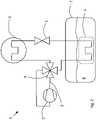
- Figure 1 schematically shows an air conditioning system 1 for a vehicle according to a first example embodiment.
- an air conditioning system 1 for a vehicle comprises a cooling line 2 adapted to transport a coolant fluid through the air conditioning system 1.
- the cooling line 2 is connected to a compressor 3, a first heat-exchanging arrangement 4, an expansion valve 5 and a cabin heat-exchanging arrangement 6.
- the first heat-exchanging arrangement 4 is in the first example embodiment a condenser.
- the cabin heat-exchanging arrangement 6 is, in the first example embodiment, an evaporator and is arranged in connection to a blower (not shown) that is arranged to blow air through the cabin heat-exchanging arrangement 6 to provide cool air into the cabin of the vehicle.
- the first heat-exchanging arrangement 4 is normally arranged in the vehicle such that ambient air can is led past the first heat-exchanging arrangement 4 in order to exchange heat between the air being led past the first heat-exchanging arrangement 4 and the coolant fluid passing through the first heat-exchanging arrangement 4.
- the first heat-exchanging arrangement 4 is arranged inside a first liquid container 7 that is arranged to hold a first liquid heat exchange medium 8.
- the first heat-exchanging arrangement 4 is arranged inside the first liquid container 7 for exchanging heat between the coolant fluid and the first liquid heat exchange medium 8.
- the first liquid heat exchange medium 8 is for instance liquid fuel such as petrol, diesel, liquefied natural gas or liquefied hydrogen.
- the first liquid container 7 is a fuel tank.
- the first liquid heat exchange medium 8 can also be windshield washer fluid.
- the first liquid container 7 is a windshield washer fluid container.
- the windshield washer container may need be made more durable, for instance by increasing the thickness of the material the windshield washer container is made of.
- the first liquid heat exchange medium 8 can also be engine oil and the first liquid container 7 is an engine oil sump.
- the first liquid heat exchange medium 8 can also be transmission oil and the first liquid container 7 is a transmission oil reservoir.
- the various heat-exchanging arrangements referred to in the description are illustrated as generic heat exchangers in the figures and can take various forms.
- the dashed line surrounding the heat-exchanging arrangements that are arranged in liquid containers illustrate the possibility that the heat-exchanging arrangements are enclosed or that they are conduits submerged in the liquid heat exchange medium.
- FIG. 2 schematically shows an air conditioning system 1 for a vehicle according to a second example embodiment.
- the air conditioning system 1 further comprises a reversing valve 9 connected to the first heat-exchanging arrangement 4.
- the reversing valve 9 is arranged to selectively reverse the flow of the coolant fluid in the air conditioning system 1.
- the reversing valve 9 is a component normally found in indoor air conditioning systems where it allows the air conditioner to selectively provide cool or hot air to the space in which it is installed. By providing the air conditioning system 1 for a vehicle with such a valve, the same function can be achieved in a vehicle.
- the design and function of the reversing valve 9 is well known and will not be described in further detail.
- the reversing valve 9 can be automatically controlled by an electronic control unit of the vehicle and based on the desired output temperature inside the cabin and the outside temperature or be manually controlled through controls inside the cabin.
- FIG 3 schematically shows an air conditioning system 1 for a vehicle according to a third example embodiment.
- the air conditioning system 1 according to figure 2 is equipped with a cooling system 10 separate from the air conditioning system 1.
- the separate cooling system 10 is arranged to condense any vapour evaporated from the first liquid heat exchange medium 8 and to return it to the first liquid container 7.
- the first liquid heat exchange medium 8 is a liquid fuel
- the condensed fuel can also be transported directly to the engine.
- the separate cooling system 10 comprises a control valve 10a and a cooler 10b.
- the cooler 10b is illustrated as a generic heat exchanger and can take various forms.
- the arrows illustrate vapour leaving the first liquid container to be cooled by the separate cooling system 10.
- a return connection or a connection to a user of the liquid condensed by the separate cooling system 10 are not shown.
- the air conditioning system 1 according to figure 1 can also be provided with a cooling system 10 separate from the air conditioning system 1.
- Figure 4 schematically shows an air conditioning system 1 for a vehicle according to a fourth example embodiment.
- the air conditioning system 1 further comprises an evaporative emission canister 11 arranged to be connected to the first liquid container 7.
- the evaporative emission container can be arranged to be connected to the cooling system 10 separate from the air conditioning system 1 as illustrated in figure 4 , or be arranged to be connected directly to the first liquid container 7.
- FIG 5 schematically shows an air conditioning system 1 for a vehicle according to a fifth example embodiment.
- the air conditioning system 1 comprises a second liquid container 12 arranged to hold a second liquid heat exchange medium 13 and a coolant fluid connection 14 arranged in the second liquid container 12 for exchanging heat between the coolant fluid and the second liquid heat exchange medium 13.
- the coolant fluid connection 14 is a straight conduit placed inside the second liquid container 12. Heat is exchanged between the coolant fluid passing through the coolant fluid connection 14 and the second liquid heat exchange medium 13.
- the first heat-exchanging arrangement 4 is in figure 5 arranged in series with the coolant fluid connection 14. This setup works well when the second liquid heat exchange medium is a windshield washer fluid.
- FIG 6 schematically shows an air conditioning system 1 for a vehicle according to a sixth example embodiment.
- the coolant fluid connection 14 is a second heat-exchanging arrangement 15 such as a condenser/evaporator (depending on the desired functionality of the air conditioning system) to increase the efficiency of the heat exchange between the coolant fluid inside the second heat-exchanging arrangement 15 and the second liquid heat exchange medium 13.
- the first heat-exchanging arrangement 4 is arranged in parallel with the coolant fluid connection 14, i.e. the second heat-exchanging arrangement 15.
- FIG 7 schematically shows a vehicle 16 comprising an air conditioning system 1 for a vehicle 16 according to figure 1 .
- the compressor 3 is in figure 7 arranged to be driven by the combustion engine 17.
- the first liquid container 7 is a fuel tank and the first heat exchange medium 4 is arranged therein.
- the cabin heat-exchanging arrangement 6 is arranged close to the cabin and is arranged to cool outside air blown past the cabin heat-exchanging arrangement 6 by a blower (not shown) into the cabin.
- the expansion valve 5 is arranged in connection to the cabin heat-exchanging arrangement 6.
- the placement of the various components of the air conditioning system 1 is for illustrative purposes only and the final placement may vary depending on the final design of the vehicle 16.
- Vehicles with an air conditioning system 1 according to the example embodiments described in conjunction with figures 2-6 are not explicitly shown. It is considered that the person skilled in the art understands how to adapt the various example embodiments of the air conditioning system in the disclosure to fit in a vehicle 16.
- the air conditioning system 1 may be implemented in an electric vehicle, utilizing one or more of the liquids available in such a vehicle.
- Figure 8 schematically show a chart showing cooling power over travel time for a sunny day.
- the chart axes are travel time t, on the horizontal axis and cooling power P, on the vertical axis.
- the air conditioning system operates at maximum cooling power to decrease the temperature in the vehicle.
- cooling power is reduced at time t2.
- time t3 Towards the end, at time t3, a lower amount of cooling power is needed to maintain a desired temperature in the cabin.
- the area under the graph is the energy E that is accumulated in the liquid heat exchange medium in the liquid container.
- the air conditioning system has to be designed for peak load cooling power as the heat exchange between the ambient air and the coolant fluid in the air conditioning system is limited.
- the coolant fluid can exchange heat with the liquid heat exchange medium in the liquid container more efficiently and thereby be designed to provide an average load cooling power.
- the energy E heats the liquid heat exchange medium, which slowly cools down over time to a temperature that is safe for a parked vehicle.
- the cooling can be made with or without assistance from a separate cooling system.
- all example embodiments may comprise a cooling system 10 separate from the air conditioning system 1.
- all example embodiments may comprise an evaporative emission canister 11, with or without a cooling system 10 separate from the air conditioning system 1.
- All example embodiments with a second liquid container 12 and a second heat-exchanging arrangement 15 may comprise at least one reversing valve 9 such that the flow of coolant fluid in the air conditioning system 1 can selectively be reversed. Controlling the air conditioning system according to the disclosure is made in the same way as today, with the necessary changes being made in the electronic control unit/units that control the vehicle's air conditioning system to adapt for the different placement of the first heat-exchanging arrangement.
Claims (13)
- Klimaanlage (1) für ein Fahrzeug (16), wobei die Klimaanlage (1) eine Kühlleitung (2), die zum Transport eines Kühlmittelfluids eingerichtet ist, und eine erste Wärmetauschanordnung (4), die mit der Kühlleitung (2) verbunden ist, umfasst,
wobei die Klimaanlage (1) einen ersten Flüssigkeitsbehälter (7) umfasst, der dafür eingerichtet ist, ein erstes flüssiges Wärmetauschmedium (8) zu tragen, und dass die erste Wärmetauschanordnung (4) innerhalb des ersten Flüssigkeitsbehälters (7) angeordnet ist zum Wärmeaustausch zwischen dem Kühlmittelfluid und dem ersten flüssigen Wärmetauschmedium (8), dadurch gekennzeichnet, dass die Klimaanlage (1) einen zweiten Flüssigkeitsbehälter (12), der dafür eingerichtet ist, ein zweites flüssiges Wärmetauschmedium (13) zu tragen, und eine Kühlmittelfluidverbindung (14), die im zweiten Flüssigkeitsbehälter (12) angeordnet ist zum Wärmeaustausch zwischen dem Kühlmittelfluid und dem zweiten Wärmetauschmedium (13), umfasst. - Klimaanlage (1) nach Anspruch 1, wobei die Anlage weiter ein Umsteuerventil (9) umfasst, das mit der ersten Wärmetauschanordnung (4) verbunden ist, indem das Umsteuerventil (9) dafür eingerichtet ist, die Strömung des Kühlmittelfluids in der Klimaanlage (1) selektiv umzusteuern.
- Klimaanlage (1) nach einem der vorgehenden Ansprüche, wobei das erste flüssige Wärmetauschmedium (8) eines von den folgenden ist:- Flüssigbrennstoff wie Benzin, Diesel, Flüssigerdgas oder Flüssigwasserstoff,- Scheibenwaschfluid,- Motoröl,- Getriebeöl.
- Klimaanlage (1) nach einem der vorgehenden Ansprüche, wobei die Anlage weiter ein von der Klimaanlage (1) getrenntes Kühlsystem (10) umfasst, das dafür eingerichtet ist, jeglichen Dampf, der vom ersten flüssigen Wärmetauschmedium (8) verdampft, zu kondensieren.
- Klimaanlage (1) nach Anspruch 3 oder 4, wobei das erste flüssige Wärmetauschmedium (8) eines von Flüssigbrennstoff wie Benzin, Diesel oder Flüssigerdgas ist, wobei die Anlage weiter einen Verdunstungsemissionsbehälter (11), der zum Verbinden mit dem Flüssigkeitsbehälter eingerichtet ist, umfasst, indem der Verdunstungsemissionsbehälter (11) dafür eingerichtet ist, Kohlenwasserstoffe, die vom ersten flüssigen Wärmetauschmedium (8) verdampfen, einzufangen.
- Klimaanlage (1) nach Anspruch 1, wobei die Kühlmittelfluidverbindung (14) eine zweite Wärmetauschanordnung (15) ist, die im zweiten Flüssigkeitsbehälter (12) angeordnet ist.
- Klimaanlage (1) nach einem der vorgehenden Ansprüche, wobei die erste Wärmetauschanordnung (4) und die zweite Wärmetauschanordnung (15) in Reihe oder parallel angeordnet sind.
- Verfahren zum Wärmetausch eines Kühlmittelfluids einer Klimaanlage (1) eines Fahrzeugs (16), wobei die Klimaanlage (1) eine Kühlleitung (2) die zum Transport eines Kühlmittelfluids eingerichtet ist, und eine erste Wärmetauschanordnung (4), die mit der Kühlleitung (2) verbunden ist, umfasst, wobei mindestens ein Flüssigkeitsbehälter dafür eingerichtet ist, ein erstes flüssiges Wärmetauschmedium (8) zu tragen, und eine erste Wärmetauschanordnung (4) innerhalb des Flüssigkeitsbehälters angeordnet ist, wobei die Klimaanlage (1) weiter einen zweiten Flüssigkeitsbehälter (12), der dafür eingerichtet ist, ein zweites flüssiges Wärmetauschmedium (13) zu tragen, und eine Kühlmittelfluidverbindung (14), die im zweiten Flüssigkeitsbehälter (12) angeordnet ist, umfasst:
wobei das Verfahren Folgendes umfasst:- Anfahren der Klimaanlage (1),- Transportieren des Kühlmittelfluids zu der ersten Wärmetauschanordnung (4),- Wärmetauschen zwischen dem Kühlmittelfluid und dem ersten flüssigen Wärmetauschmedium (8) zur Verringerung der Temperatur des Kühlmittelfluids,- Transportieren von Kühlmittelfluid zur Kühlmittelfluidverbindung (14),- Wärmetauschen zwischen dem Kühlmittelfluid und dem zweiten flüssigen Wärmetauschmedium (13). - Verfahren nach Anspruch 8, wobei die Anlage weiter ein Umsteuerventil (9) umfasst, das mit der ersten Wärmetauschanordnung (4) verbunden ist und dafür eingerichtet ist, die Strömung des Kühlmittelfluids in der Klimaanlage (1) selektiv umzusteuern, wobei das Verfahren Folgendes umfasst:- Transportieren des Kühlmittelfluids zu der ersten Wärmetauschanordnung (4),- Wärmetauschen zwischen dem Kühlmittelfluid und dem ersten flüssigen Wärmetauschmedium (8) zur Erhöhung der Temperatur des Kühlmittelfluids.
- Verfahren nach Anspruch 8 oder 9, wobei das Verfahren Folgendes umfasst:- Kondensieren von jeglichem Dampf, der vom ersten flüssigen Wärmetauschmedium (8) im Flüssigkeitsbehälter durch den Wärmetausch mit dem Kühlmittelfluid in der ersten Wärmetauschanordnung (4) durch ein von der Klimaanlage (1) getrenntes Kühlsystem (10) verdampft.
- Verfahren nach einem der Ansprüche 8-10, wobei das Verfahren Folgendes umfasst:- Einfangen von Kohlenwasserstoffen, die vom ersten flüssigen Wärmetauschmedium (8) des ersten Flüssigkeitsbehälters (7) durch einen Verdunstungsemissionsbehälter (11) verdampfen, der dafür eingerichtet ist, mit dem ersten Flüssigkeitsbehälter (7) verbunden zu werden, wenn das erste flüssige Wärmetauschmedium (8) eines von Flüssigbrennstoff wie Benzin, Diesel oder Flüssigerdgas ist.
- Verfahren nach einem der Ansprüche 8-11, wobei das Verfahren Folgendes umfasst:- Transportieren von Kühlmittelfluid zu einer zweiten Wärmetauschanordnung (15), die im zweiten Flüssigkeitsbehälter (12) angeordnet ist.
- Fahrzeug (16), das eine Klimaanlage (1) nach einem der Ansprüche 1-7 umfasst.
Priority Applications (4)
| Application Number | Priority Date | Filing Date | Title |
|---|---|---|---|
| EP19199686.7A EP3798030B1 (de) | 2019-09-25 | 2019-09-25 | Klimaanlage für ein fahrzeug |
| PCT/CN2020/116442 WO2021057645A1 (en) | 2019-09-25 | 2020-09-21 | Air conditioning system for a vehicle |
| CN202080065385.3A CN114401854A (zh) | 2019-09-25 | 2020-09-21 | 用于车辆的空调系统 |
| US17/693,331 US20220194173A1 (en) | 2019-09-25 | 2022-03-12 | Air conditioning system for a vehicle |
Applications Claiming Priority (1)
| Application Number | Priority Date | Filing Date | Title |
|---|---|---|---|
| EP19199686.7A EP3798030B1 (de) | 2019-09-25 | 2019-09-25 | Klimaanlage für ein fahrzeug |
Publications (2)
| Publication Number | Publication Date |
|---|---|
| EP3798030A1 EP3798030A1 (de) | 2021-03-31 |
| EP3798030B1 true EP3798030B1 (de) | 2022-08-03 |
Family
ID=68069613
Family Applications (1)
| Application Number | Title | Priority Date | Filing Date |
|---|---|---|---|
| EP19199686.7A Active EP3798030B1 (de) | 2019-09-25 | 2019-09-25 | Klimaanlage für ein fahrzeug |
Country Status (4)
| Country | Link |
|---|---|
| US (1) | US20220194173A1 (de) |
| EP (1) | EP3798030B1 (de) |
| CN (1) | CN114401854A (de) |
| WO (1) | WO2021057645A1 (de) |
Families Citing this family (1)
| Publication number | Priority date | Publication date | Assignee | Title |
|---|---|---|---|---|
| CN113119686B (zh) * | 2021-04-29 | 2022-07-19 | 上海中科深江电动车辆有限公司 | 增程车辆中实现冷却介质交换的系统及其控制方法 |
Family Cites Families (37)
| Publication number | Priority date | Publication date | Assignee | Title |
|---|---|---|---|---|
| US5138851A (en) * | 1990-12-14 | 1992-08-18 | Golden Empire Trading Co., Inc. | Active seat cooling system |
| DE4341756C2 (de) * | 1993-12-08 | 2001-08-02 | Behr Gmbh & Co | Klimaanlage für ein Kraftfahrzeug |
| JP3740763B2 (ja) * | 1996-11-15 | 2006-02-01 | 株式会社デンソー | 冷房装置 |
| US6161613A (en) * | 1996-11-21 | 2000-12-19 | Carrier Corporation | Low pressure drop heat exchanger |
| JPH10211816A (ja) | 1997-01-30 | 1998-08-11 | Showa Alum Corp | 原動機付設冷却装置 |
| FR2796336B1 (fr) * | 1999-07-12 | 2001-10-05 | Valeo Climatisation | Vehicule comprenant une installation de chauffage-climatisation |
| FR2824388A1 (fr) * | 2001-05-07 | 2002-11-08 | Italinnova Sas | Generateur de froid pour installation de climatisation de vehicule |
| US6540815B1 (en) * | 2001-11-21 | 2003-04-01 | Meadwestvaco Corporation | Method for reducing emissions from evaporative emissions control systems |
| FR2834778B1 (fr) * | 2002-01-16 | 2004-04-16 | Renault | Dispositif de gestion thermique, notamment pour vehicule automobile equipe d'une pile a combustible |
| JP4276605B2 (ja) * | 2004-09-29 | 2009-06-10 | 株式会社豊田自動織機 | 水素ステーション及び車両 |
| JP4542414B2 (ja) * | 2004-11-18 | 2010-09-15 | 株式会社豊田自動織機 | 水素燃料自動車における水素タンク冷却装置 |
| US7640967B2 (en) * | 2005-10-12 | 2010-01-05 | International Truck Intellectual Property Company, Llc | Thermosyphon heat reduction system for a motor vehicle engine compartment |
| JP4201011B2 (ja) * | 2006-03-27 | 2008-12-24 | トヨタ自動車株式会社 | 蓄熱装置 |
| JP2009190687A (ja) * | 2008-02-18 | 2009-08-27 | Calsonic Kansei Corp | 車両用空気調和システム |
| CN201212753Y (zh) * | 2008-05-12 | 2009-03-25 | 凌建军 | 以液体作为吸冷介质的高效节能多功能制冷装置 |
| JP2010243118A (ja) * | 2009-04-09 | 2010-10-28 | Toyota Industries Corp | 蓄熱装置及び車両用空調装置 |
| GB2471506A (en) * | 2009-07-02 | 2011-01-05 | Agco Gmbh | Vehicle heat exchange system |
| US20110259285A1 (en) * | 2010-04-26 | 2011-10-27 | Toyota Jidosha Kabushiki Kaisha | Ammonia burning internal combustion engine |
| DE102011013005A1 (de) * | 2011-03-04 | 2012-09-06 | Iav Gmbh Ingenieurgesellschaft Auto Und Verkehr | Tankentlüftungs- und Kühlsystem für Hybridfahrzeuge |
| JP5703884B2 (ja) * | 2011-03-23 | 2015-04-22 | トヨタ自動車株式会社 | 電池パックのリサイクル方法及び処理装置 |
| US9186953B2 (en) * | 2011-06-24 | 2015-11-17 | Frederico Burke | Intake enhancement system for vehicle |
| EP2667008A1 (de) * | 2012-05-25 | 2013-11-27 | Inergy Automotive Systems Research (Société Anonyme) | Verfahren und System zur Erkennung eines Lecks in einem Kraftstoffsystem |
| JP5972044B2 (ja) * | 2012-05-18 | 2016-08-17 | 日本発條株式会社 | 車両用空調システムおよび車両用シート |
| JP6103186B2 (ja) * | 2012-11-20 | 2017-03-29 | パナソニックIpマネジメント株式会社 | 車両用ヒートポンプ装置および車両用空調装置 |
| WO2014084103A1 (ja) * | 2012-11-27 | 2014-06-05 | トヨタ自動車株式会社 | 燃料タンク構造 |
| CN102997508A (zh) * | 2012-12-14 | 2013-03-27 | 广东奥马电器股份有限公司 | 水直冷双效冷凝器及冰箱 |
| US9493051B2 (en) * | 2014-08-08 | 2016-11-15 | Antwanette Bills | Chilled vehicle fuel storage tank |
| US20170370332A1 (en) * | 2015-01-07 | 2017-12-28 | Carrier Corporation | Fuel cooling system and method |
| US9945333B2 (en) * | 2015-10-20 | 2018-04-17 | The ITB Group | Fuel vapor recovery |
| PL227463B1 (pl) * | 2016-04-18 | 2017-12-29 | Lubelska Polt | Sposób i układ magazynowania ciepła albo chłodu w pojazdach z napędem elektrycznym |
| DE102017012125A1 (de) * | 2017-12-29 | 2019-07-04 | Eco ice Kälte GmbH | Wärmeübertragungseinrichtung für die Kältebereitstellung in Kühlfahrzeugen, deren Kraftfahrzeugmotor mit LNG angetrieben wird |
| EP3640069B1 (de) * | 2018-10-16 | 2021-05-05 | Magna Energy Storage Systems GesmbH | Kraftfahrzeug mit flüssigkeitsbehälter |
| CN109841363A (zh) * | 2019-01-31 | 2019-06-04 | 中国人民解放军海军工程大学 | 一种大功率蒸发冷却电阻器及冷却方法 |
| EP3711997B1 (de) * | 2019-03-18 | 2022-06-29 | Ningbo Geely Automobile Research & Development Co. Ltd. | Handhabung von kraftstoffdampf |
| EP4026718A4 (de) * | 2019-09-02 | 2022-09-07 | NISSAN MOTOR Co., Ltd. | Wärmetauschervorrichtung für ein fahrzeug |
| KR20210132913A (ko) * | 2020-04-28 | 2021-11-05 | 현대자동차주식회사 | 자율주행 제어기용 냉각 시스템 제어방법 |
| EP4246063A1 (de) * | 2022-03-15 | 2023-09-20 | Carrier Corporation | Transport-kühleinheit |
-
2019
- 2019-09-25 EP EP19199686.7A patent/EP3798030B1/de active Active
-
2020
- 2020-09-21 WO PCT/CN2020/116442 patent/WO2021057645A1/en active Application Filing
- 2020-09-21 CN CN202080065385.3A patent/CN114401854A/zh active Pending
-
2022
- 2022-03-12 US US17/693,331 patent/US20220194173A1/en active Pending
Also Published As
| Publication number | Publication date |
|---|---|
| US20220194173A1 (en) | 2022-06-23 |
| EP3798030A1 (de) | 2021-03-31 |
| CN114401854A (zh) | 2022-04-26 |
| WO2021057645A1 (en) | 2021-04-01 |
Similar Documents
| Publication | Publication Date | Title |
|---|---|---|
| US11407275B2 (en) | Heat flow management device and method for operating a heat flow management device | |
| US10773586B2 (en) | Motor vehicle with a cooling system | |
| US8215432B2 (en) | Battery thermal system for vehicle | |
| KR102320361B1 (ko) | 차량 객실 가열 회로 및 배터리 가열 회로를 구비한 차량용 열 펌프 장치 | |
| US7845187B2 (en) | Thermal management system and method for automotive vehicle | |
| US6370903B1 (en) | Heat-pump type air conditioning and heating system for fuel cell vehicles | |
| US9242527B2 (en) | Refrigerant circuit of an HVAC system of a motor vehicle | |
| JP5678137B2 (ja) | 自動車の熱分散のための装置及び方法 | |
| US11214126B2 (en) | Air conditioning system of a motor vehicle and method for operating the air conditioning system | |
| US20200076029A1 (en) | Method for the climate control of a battery electric vehicle | |
| US20090249807A1 (en) | HVAC and Battery Thermal Management for a Vehicle | |
| US20120247716A1 (en) | Motor Vehicle Cooling System | |
| US9783025B2 (en) | Method for cooling and/or heating media, preferably in a motor vehicle, and a sorptive heat and cold storage system | |
| CN110435390A (zh) | 一种适用于低温工况下新能源汽车的整车热管理系统 | |
| US20120132392A1 (en) | Temperature control apparatus for vehicle | |
| WO2011000852A1 (en) | Heat exchange system for use on vehicles | |
| US20220194173A1 (en) | Air conditioning system for a vehicle | |
| US11780298B2 (en) | Heat utilisation in an environmental control system | |
| WO2019029218A1 (zh) | 汽车空调系统 | |
| CN209381734U (zh) | 一种用于电动汽车的热管理系统 | |
| CN116512864B (zh) | 混合动力车辆热量管理系统和混合动力车辆 | |
| CN117360174B (zh) | 一种燃料电池汽车耦合热管理系统 | |
| CN114475149B (zh) | 电动汽车热泵系统及电动汽车 | |
| US20230373272A1 (en) | Thermal system of a motor vehicle and method of operating the thermal system | |
| JP2024518388A (ja) | 車両のための加熱及び冷却システム |
Legal Events
| Date | Code | Title | Description |
|---|---|---|---|
| PUAI | Public reference made under article 153(3) epc to a published international application that has entered the european phase |
Free format text: ORIGINAL CODE: 0009012 |
|
| STAA | Information on the status of an ep patent application or granted ep patent |
Free format text: STATUS: REQUEST FOR EXAMINATION WAS MADE |
|
| 17P | Request for examination filed |
Effective date: 20190925 |
|
| AK | Designated contracting states |
Kind code of ref document: A1 Designated state(s): AL AT BE BG CH CY CZ DE DK EE ES FI FR GB GR HR HU IE IS IT LI LT LU LV MC MK MT NL NO PL PT RO RS SE SI SK SM TR |
|
| AX | Request for extension of the european patent |
Extension state: BA ME |
|
| GRAP | Despatch of communication of intention to grant a patent |
Free format text: ORIGINAL CODE: EPIDOSNIGR1 |
|
| STAA | Information on the status of an ep patent application or granted ep patent |
Free format text: STATUS: GRANT OF PATENT IS INTENDED |
|
| RIC1 | Information provided on ipc code assigned before grant |
Ipc: B60K 15/035 20060101ALI20220209BHEP Ipc: B60H 1/32 20060101ALI20220209BHEP Ipc: B60H 1/00 20060101AFI20220209BHEP |
|
| INTG | Intention to grant announced |
Effective date: 20220315 |
|
| GRAS | Grant fee paid |
Free format text: ORIGINAL CODE: EPIDOSNIGR3 |
|
| GRAA | (expected) grant |
Free format text: ORIGINAL CODE: 0009210 |
|
| STAA | Information on the status of an ep patent application or granted ep patent |
Free format text: STATUS: THE PATENT HAS BEEN GRANTED |
|
| AK | Designated contracting states |
Kind code of ref document: B1 Designated state(s): AL AT BE BG CH CY CZ DE DK EE ES FI FR GB GR HR HU IE IS IT LI LT LU LV MC MK MT NL NO PL PT RO RS SE SI SK SM TR |
|
| REG | Reference to a national code |
Ref country code: AT Ref legal event code: REF Ref document number: 1508461 Country of ref document: AT Kind code of ref document: T Effective date: 20220815 Ref country code: CH Ref legal event code: EP |
|
| REG | Reference to a national code |
Ref country code: DE Ref legal event code: R096 Ref document number: 602019017701 Country of ref document: DE |
|
| REG | Reference to a national code |
Ref country code: IE Ref legal event code: FG4D |
|
| REG | Reference to a national code |
Ref country code: LT Ref legal event code: MG9D |
|
| REG | Reference to a national code |
Ref country code: NL Ref legal event code: MP Effective date: 20220803 |
|
| PG25 | Lapsed in a contracting state [announced via postgrant information from national office to epo] |
Ref country code: SE Free format text: LAPSE BECAUSE OF FAILURE TO SUBMIT A TRANSLATION OF THE DESCRIPTION OR TO PAY THE FEE WITHIN THE PRESCRIBED TIME-LIMIT Effective date: 20220803 Ref country code: RS Free format text: LAPSE BECAUSE OF FAILURE TO SUBMIT A TRANSLATION OF THE DESCRIPTION OR TO PAY THE FEE WITHIN THE PRESCRIBED TIME-LIMIT Effective date: 20220803 Ref country code: PT Free format text: LAPSE BECAUSE OF FAILURE TO SUBMIT A TRANSLATION OF THE DESCRIPTION OR TO PAY THE FEE WITHIN THE PRESCRIBED TIME-LIMIT Effective date: 20221205 Ref country code: NO Free format text: LAPSE BECAUSE OF FAILURE TO SUBMIT A TRANSLATION OF THE DESCRIPTION OR TO PAY THE FEE WITHIN THE PRESCRIBED TIME-LIMIT Effective date: 20221103 Ref country code: NL Free format text: LAPSE BECAUSE OF FAILURE TO SUBMIT A TRANSLATION OF THE DESCRIPTION OR TO PAY THE FEE WITHIN THE PRESCRIBED TIME-LIMIT Effective date: 20220803 Ref country code: LV Free format text: LAPSE BECAUSE OF FAILURE TO SUBMIT A TRANSLATION OF THE DESCRIPTION OR TO PAY THE FEE WITHIN THE PRESCRIBED TIME-LIMIT Effective date: 20220803 Ref country code: LT Free format text: LAPSE BECAUSE OF FAILURE TO SUBMIT A TRANSLATION OF THE DESCRIPTION OR TO PAY THE FEE WITHIN THE PRESCRIBED TIME-LIMIT Effective date: 20220803 Ref country code: FI Free format text: LAPSE BECAUSE OF FAILURE TO SUBMIT A TRANSLATION OF THE DESCRIPTION OR TO PAY THE FEE WITHIN THE PRESCRIBED TIME-LIMIT Effective date: 20220803 Ref country code: ES Free format text: LAPSE BECAUSE OF FAILURE TO SUBMIT A TRANSLATION OF THE DESCRIPTION OR TO PAY THE FEE WITHIN THE PRESCRIBED TIME-LIMIT Effective date: 20220803 |
|
| REG | Reference to a national code |
Ref country code: AT Ref legal event code: MK05 Ref document number: 1508461 Country of ref document: AT Kind code of ref document: T Effective date: 20220803 |
|
| PG25 | Lapsed in a contracting state [announced via postgrant information from national office to epo] |
Ref country code: PL Free format text: LAPSE BECAUSE OF FAILURE TO SUBMIT A TRANSLATION OF THE DESCRIPTION OR TO PAY THE FEE WITHIN THE PRESCRIBED TIME-LIMIT Effective date: 20220803 Ref country code: IS Free format text: LAPSE BECAUSE OF FAILURE TO SUBMIT A TRANSLATION OF THE DESCRIPTION OR TO PAY THE FEE WITHIN THE PRESCRIBED TIME-LIMIT Effective date: 20221203 Ref country code: HR Free format text: LAPSE BECAUSE OF FAILURE TO SUBMIT A TRANSLATION OF THE DESCRIPTION OR TO PAY THE FEE WITHIN THE PRESCRIBED TIME-LIMIT Effective date: 20220803 |
|
| PG25 | Lapsed in a contracting state [announced via postgrant information from national office to epo] |
Ref country code: SM Free format text: LAPSE BECAUSE OF FAILURE TO SUBMIT A TRANSLATION OF THE DESCRIPTION OR TO PAY THE FEE WITHIN THE PRESCRIBED TIME-LIMIT Effective date: 20220803 Ref country code: RO Free format text: LAPSE BECAUSE OF FAILURE TO SUBMIT A TRANSLATION OF THE DESCRIPTION OR TO PAY THE FEE WITHIN THE PRESCRIBED TIME-LIMIT Effective date: 20220803 Ref country code: DK Free format text: LAPSE BECAUSE OF FAILURE TO SUBMIT A TRANSLATION OF THE DESCRIPTION OR TO PAY THE FEE WITHIN THE PRESCRIBED TIME-LIMIT Effective date: 20220803 Ref country code: CZ Free format text: LAPSE BECAUSE OF FAILURE TO SUBMIT A TRANSLATION OF THE DESCRIPTION OR TO PAY THE FEE WITHIN THE PRESCRIBED TIME-LIMIT Effective date: 20220803 Ref country code: AT Free format text: LAPSE BECAUSE OF FAILURE TO SUBMIT A TRANSLATION OF THE DESCRIPTION OR TO PAY THE FEE WITHIN THE PRESCRIBED TIME-LIMIT Effective date: 20220803 |
|
| REG | Reference to a national code |
Ref country code: CH Ref legal event code: PL |
|
| REG | Reference to a national code |
Ref country code: DE Ref legal event code: R097 Ref document number: 602019017701 Country of ref document: DE |
|
| REG | Reference to a national code |
Ref country code: BE Ref legal event code: MM Effective date: 20220930 |
|
| PG25 | Lapsed in a contracting state [announced via postgrant information from national office to epo] |
Ref country code: SK Free format text: LAPSE BECAUSE OF FAILURE TO SUBMIT A TRANSLATION OF THE DESCRIPTION OR TO PAY THE FEE WITHIN THE PRESCRIBED TIME-LIMIT Effective date: 20220803 Ref country code: MC Free format text: LAPSE BECAUSE OF FAILURE TO SUBMIT A TRANSLATION OF THE DESCRIPTION OR TO PAY THE FEE WITHIN THE PRESCRIBED TIME-LIMIT Effective date: 20220803 Ref country code: EE Free format text: LAPSE BECAUSE OF FAILURE TO SUBMIT A TRANSLATION OF THE DESCRIPTION OR TO PAY THE FEE WITHIN THE PRESCRIBED TIME-LIMIT Effective date: 20220803 |
|
| PLBE | No opposition filed within time limit |
Free format text: ORIGINAL CODE: 0009261 |
|
| STAA | Information on the status of an ep patent application or granted ep patent |
Free format text: STATUS: NO OPPOSITION FILED WITHIN TIME LIMIT |
|
| PG25 | Lapsed in a contracting state [announced via postgrant information from national office to epo] |
Ref country code: LU Free format text: LAPSE BECAUSE OF NON-PAYMENT OF DUE FEES Effective date: 20220925 Ref country code: AL Free format text: LAPSE BECAUSE OF FAILURE TO SUBMIT A TRANSLATION OF THE DESCRIPTION OR TO PAY THE FEE WITHIN THE PRESCRIBED TIME-LIMIT Effective date: 20220803 |
|
| 26N | No opposition filed |
Effective date: 20230504 |
|
| PG25 | Lapsed in a contracting state [announced via postgrant information from national office to epo] |
Ref country code: LI Free format text: LAPSE BECAUSE OF NON-PAYMENT OF DUE FEES Effective date: 20220930 Ref country code: IE Free format text: LAPSE BECAUSE OF NON-PAYMENT OF DUE FEES Effective date: 20220925 Ref country code: CH Free format text: LAPSE BECAUSE OF NON-PAYMENT OF DUE FEES Effective date: 20220930 |
|
| PG25 | Lapsed in a contracting state [announced via postgrant information from national office to epo] |
Ref country code: SI Free format text: LAPSE BECAUSE OF FAILURE TO SUBMIT A TRANSLATION OF THE DESCRIPTION OR TO PAY THE FEE WITHIN THE PRESCRIBED TIME-LIMIT Effective date: 20220803 |
|
| PG25 | Lapsed in a contracting state [announced via postgrant information from national office to epo] |
Ref country code: BE Free format text: LAPSE BECAUSE OF NON-PAYMENT OF DUE FEES Effective date: 20220930 |
|
| PGFP | Annual fee paid to national office [announced via postgrant information from national office to epo] |
Ref country code: GB Payment date: 20230920 Year of fee payment: 5 |
|
| PGFP | Annual fee paid to national office [announced via postgrant information from national office to epo] |
Ref country code: FR Payment date: 20230927 Year of fee payment: 5 Ref country code: DE Payment date: 20230911 Year of fee payment: 5 |
|
| PG25 | Lapsed in a contracting state [announced via postgrant information from national office to epo] |
Ref country code: CY Free format text: LAPSE BECAUSE OF FAILURE TO SUBMIT A TRANSLATION OF THE DESCRIPTION OR TO PAY THE FEE WITHIN THE PRESCRIBED TIME-LIMIT Effective date: 20220803 |