EP3727969B1 - Aggregat mit wenigstens einem kolben mit einer zugeordneten kolbenfeder - Google Patents
Aggregat mit wenigstens einem kolben mit einer zugeordneten kolbenfeder Download PDFInfo
- Publication number
- EP3727969B1 EP3727969B1 EP18789648.5A EP18789648A EP3727969B1 EP 3727969 B1 EP3727969 B1 EP 3727969B1 EP 18789648 A EP18789648 A EP 18789648A EP 3727969 B1 EP3727969 B1 EP 3727969B1
- Authority
- EP
- European Patent Office
- Prior art keywords
- piston
- assembly tool
- assembly
- spring
- piston spring
- Prior art date
- Legal status (The legal status is an assumption and is not a legal conclusion. Google has not performed a legal analysis and makes no representation as to the accuracy of the status listed.)
- Active
Links
Images

Classifications
-
- B—PERFORMING OPERATIONS; TRANSPORTING
- B60—VEHICLES IN GENERAL
- B60T—VEHICLE BRAKE CONTROL SYSTEMS OR PARTS THEREOF; BRAKE CONTROL SYSTEMS OR PARTS THEREOF, IN GENERAL; ARRANGEMENT OF BRAKING ELEMENTS ON VEHICLES IN GENERAL; PORTABLE DEVICES FOR PREVENTING UNWANTED MOVEMENT OF VEHICLES; VEHICLE MODIFICATIONS TO FACILITATE COOLING OF BRAKES
- B60T11/00—Transmitting braking action from initiating means to ultimate brake actuator without power assistance or drive or where such assistance or drive is irrelevant
- B60T11/10—Transmitting braking action from initiating means to ultimate brake actuator without power assistance or drive or where such assistance or drive is irrelevant transmitting by fluid means, e.g. hydraulic
- B60T11/16—Master control, e.g. master cylinders
- B60T11/20—Tandem, side-by-side, or other multiple master cylinder units
-
- B—PERFORMING OPERATIONS; TRANSPORTING
- B60—VEHICLES IN GENERAL
- B60T—VEHICLE BRAKE CONTROL SYSTEMS OR PARTS THEREOF; BRAKE CONTROL SYSTEMS OR PARTS THEREOF, IN GENERAL; ARRANGEMENT OF BRAKING ELEMENTS ON VEHICLES IN GENERAL; PORTABLE DEVICES FOR PREVENTING UNWANTED MOVEMENT OF VEHICLES; VEHICLE MODIFICATIONS TO FACILITATE COOLING OF BRAKES
- B60T11/00—Transmitting braking action from initiating means to ultimate brake actuator without power assistance or drive or where such assistance or drive is irrelevant
- B60T11/10—Transmitting braking action from initiating means to ultimate brake actuator without power assistance or drive or where such assistance or drive is irrelevant transmitting by fluid means, e.g. hydraulic
- B60T11/16—Master control, e.g. master cylinders
-
- F—MECHANICAL ENGINEERING; LIGHTING; HEATING; WEAPONS; BLASTING
- F15—FLUID-PRESSURE ACTUATORS; HYDRAULICS OR PNEUMATICS IN GENERAL
- F15B—SYSTEMS ACTING BY MEANS OF FLUIDS IN GENERAL; FLUID-PRESSURE ACTUATORS, e.g. SERVOMOTORS; DETAILS OF FLUID-PRESSURE SYSTEMS, NOT OTHERWISE PROVIDED FOR
- F15B15/00—Fluid-actuated devices for displacing a member from one position to another; Gearing associated therewith
- F15B15/08—Characterised by the construction of the motor unit
- F15B15/14—Characterised by the construction of the motor unit of the straight-cylinder type
- F15B15/1423—Component parts; Constructional details
- F15B15/1447—Pistons; Piston to piston rod assemblies
-
- F—MECHANICAL ENGINEERING; LIGHTING; HEATING; WEAPONS; BLASTING
- F16—ENGINEERING ELEMENTS AND UNITS; GENERAL MEASURES FOR PRODUCING AND MAINTAINING EFFECTIVE FUNCTIONING OF MACHINES OR INSTALLATIONS; THERMAL INSULATION IN GENERAL
- F16D—COUPLINGS FOR TRANSMITTING ROTATION; CLUTCHES; BRAKES
- F16D65/00—Parts or details
- F16D65/0043—Brake maintenance and assembly, tools therefor
-
- B—PERFORMING OPERATIONS; TRANSPORTING
- B60—VEHICLES IN GENERAL
- B60Y—INDEXING SCHEME RELATING TO ASPECTS CROSS-CUTTING VEHICLE TECHNOLOGY
- B60Y2400/00—Special features of vehicle units
- B60Y2400/81—Braking systems
-
- B—PERFORMING OPERATIONS; TRANSPORTING
- B60—VEHICLES IN GENERAL
- B60Y—INDEXING SCHEME RELATING TO ASPECTS CROSS-CUTTING VEHICLE TECHNOLOGY
- B60Y2410/00—Constructional features of vehicle sub-units
- B60Y2410/10—Housings
-
- B—PERFORMING OPERATIONS; TRANSPORTING
- B60—VEHICLES IN GENERAL
- B60Y—INDEXING SCHEME RELATING TO ASPECTS CROSS-CUTTING VEHICLE TECHNOLOGY
- B60Y2410/00—Constructional features of vehicle sub-units
- B60Y2410/13—Materials or fluids with special properties
- B60Y2410/132—Magnetic, e.g. permanent magnets
-
- F—MECHANICAL ENGINEERING; LIGHTING; HEATING; WEAPONS; BLASTING
- F15—FLUID-PRESSURE ACTUATORS; HYDRAULICS OR PNEUMATICS IN GENERAL
- F15B—SYSTEMS ACTING BY MEANS OF FLUIDS IN GENERAL; FLUID-PRESSURE ACTUATORS, e.g. SERVOMOTORS; DETAILS OF FLUID-PRESSURE SYSTEMS, NOT OTHERWISE PROVIDED FOR
- F15B2215/00—Fluid-actuated devices for displacing a member from one position to another
- F15B2215/30—Constructional details thereof
-
- F—MECHANICAL ENGINEERING; LIGHTING; HEATING; WEAPONS; BLASTING
- F16—ENGINEERING ELEMENTS AND UNITS; GENERAL MEASURES FOR PRODUCING AND MAINTAINING EFFECTIVE FUNCTIONING OF MACHINES OR INSTALLATIONS; THERMAL INSULATION IN GENERAL
- F16D—COUPLINGS FOR TRANSMITTING ROTATION; CLUTCHES; BRAKES
- F16D2250/00—Manufacturing; Assembly
- F16D2250/0084—Assembly or disassembly
Definitions
- the invention relates to a unit with the features according to the preamble of claim 1, in particular a master brake cylinder for a hydraulic motor vehicle brake system.
- Units of this type with pistons that can be displaced axially in a bore and to which a piston spring, in particular a return spring, is assigned are known and widespread in a wide variety of configurations.
- the aim is to form separate assembly units or assembly groups, which each include the piston spring with the associated piston and to design the interface between the piston spring and piston captively tied.
- a tandem master brake cylinder with an aluminum housing for a motor vehicle brake application in which the piston spring on the primary piston is tied to the piston via a displaceable and captive sleeve on a mandrel on the piston by means of riveting.
- the piston spring is permanently clamped with its inner diameter at the piston-side end via an interference fit on a central pin on the piston. The bondage of the piston spring to the associated piston also remains in operation of the unit.
- the invention is therefore based on the task of offering an improved unit and a method with which the piston and the piston spring can be mounted more effectively and while avoiding the aforementioned disadvantages in the unit and requirements for pre-assembly, interface dimensional accuracy and the variety of parts when creating variants are reduced as far as possible could become.
- the invention provides that for the assembly of the piston with the piston spring in the unit, an assembly unit is provided which comprises the piston and the piston spring.
- the piston spring is made of a magnetic or magnetizable material, in particular a ferromagnetic material such as spring steel, and the piston is made of a non-magnetic material such as plastic or light metal. The piston spring can thus be held in the assembly unit by a magnetic field on the piston.
- Pre-assembly is completely eliminated or can at least be significantly reduced. Since there is no pressing or riveting, chipping is excluded.
- the magnetic field can be generated by a magnetic element, which is arranged in an assembly tool to be removed after the insertion of the assembly unit, so that the piston is positioned and clamped between the magnetic element and the piston spring during assembly.
- the piston is essentially sleeve-shaped with a bottom and a tubular wall, with an inside of the wall and an inside of the bottom delimiting a piston interior in the piston and the piston spring being arranged at least in regions in the piston interior.
- the magnet element can preferably be positioned in the area of the outside of the base for assembly, so that the piston spring is pushed against the inside of the base by the magnetic field is pressed. This can also significantly simplify the piston/assembly tool interface.
- the piston spring is functionally arranged coaxially to the piston.
- a projection that extends into the interior of the piston and has an at least partially conical outer contour section can be arranged on the inside of the base.
- the piston spring can have a loose fit with respect to the shoulder and the wall of the piston.
- a piston spring can, for example, be paired with several piston variants, which is advantageous for standardization, and vice versa.
- the variety of parts or the scope of parts are reduced in a cost-effective manner.
- the magnetic element can be designed as a permanent magnet, as a result of which the assembly tool can be constructed in a particularly simple manner and without the need for electricity.
- the magnetic element can also be designed as an electromagnet, whose magnetic field is present when the magnetic element is in an activated state and is not present or not sufficiently present in a deactivated state of the magnetic element.
- the assembly process can thus be made particularly simple, because the assembly unit and the assembly tool can be reliably and effectively adhered to and separated from one another by simply actuating the electromagnet.
- the advantages of the invention are used particularly effectively when the unit is designed as a master brake cylinder of a motor vehicle brake system, preferably in a tandem design with two pistons arranged coaxially one behind the other with associated piston springs.
- the invention also claims an associated, effectively simplified assembly tool for assembling the assembly unit according to the invention, which has an interface for touching the piston and at least one magnetic element in the area of the interface.
- the need to hold the piston in place by means of complex mechanical or pneumatic devices can be eliminated or at least significantly simplified.
- the invention claims an advantageous assembly method for assembling the piston with the associated piston spring, which comprises the following process steps: Forming an assembly unit by bringing the piston together with a spatially aligned piston spring into a magnetic field of the assembly tool at an intended piston/assembly tool interface, the insertion the assembly unit into the cavity in the housing of the unit and separating the assembly tool from the piston.
- the advantageous assembly process the time-consuming pre-assembly can be omitted, the overall effort for the assembly of the unit is thereby reduced and the assembly systems are significantly simplified and standardized.
- a high degree of automation is also promoted with the assembly method according to the invention.
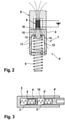
- Fig.1 shows a sectional view of an as yet incompletely constructed unit 1 according to the invention with a first embodiment of an assembly unit 6 and the assembly tool 9 when inserted into the cavity 15 of the housing 2.
- the unit 1 is designed, for example, as a master brake cylinder in a tandem design for a hydraulic motor vehicle brake system.
- the unit 1 includes a housing 2 made of a non-magnetic aluminum alloy.
- a bag-shaped cavity 15 is provided in the housing 2 and is designed as a bore 3 in some areas for guiding the piston 4 .
- Sealing elements 18, 18' arranged in separate grooves of the bore 3 are provided for sliding on the radial outer surface of the piston 4 in a sealing manner.
- the piston 4 essentially consists of a non-magnetic material. Plastics in particular, but also light metals and light metal alloys can be used for this within the invention.
- the piston 4 is essentially sleeve-shaped and has a base 10 and a tubular wall 11.
- the inner sides of the wall 11 and the base 10 thus delimit a piston interior 12 in the piston 4 in which a piston spring 5 is accommodated in some areas and loosely without being jammed.
- the piston spring 5 serves as a return spring. It is supported axially against the inside of the base 10, is compressed when the piston 4 is actuated and moves the piston 4 into its unactuated starting position at the end of the actuation process.
- the piston spring 5 is made of a magnetic or a magnetizable material, in particular a ferromagnetic material such as spring steel, and thus reacts to magnetic fields.
- the piston spring 5 is combined with the piston 4 to form an assembly unit 6 .
- An assembly tool 9 is used to hold and insert the assembly unit 6 into the cavity 15.
- a magnetic element 8 is arranged in the assembly tool 9, which generates a magnetic field 7.
- the piston 5 rests against an interface 16 on the assembly tool 9 with the outside of its base 10 .
- the magnetic element 8 is in the immediate vicinity of the bottom 10 of the piston 4.
- the magnetic field 7 penetrates the piston 4 and pulls the piston spring 5 towards the magnetic element 8, so that the piston spring 5 is pressed against the inside of the bottom 10 and so in the Assembly unit 6 is held. In this state, the assembly unit 6 can be inserted into the cavity 15 with the assembly tool 9 .
- the assembly tool 9 is separated from the piston 4 and guided out of the housing 2 .
- a slide 17 that can be displaced axially relative to the assembly tool 9 can be used within the invention, for example.
- the piston 4 is held in position by the slide 17 while the assembly tool 9 is moved back until the force of attraction of the magnetic field 7 is no longer sufficient to hold the piston 4 in place on the assembly tool 9 by the contact force of the piston spring 5 attracted by the magnetic field 7.
- the clamping force of the sealing elements 18, 18' can be used to keep the piston 4 inside of the housing 2 while the assembly tool 9 is pulled out while overcoming the magnetic attraction force.
- the magnet element 8 is designed as an annular permanent magnet, but other designs are also permissible within the invention.
- the magnetic element 8 is designed here as an electromagnet, the magnetic field 7 of which is only present in an activated state.
- the magnetic element 8 is activated and, after the desired position has been reached, is deactivated so that the assembly tool 9 can be easily pulled out.
- a projection 13 is provided on the inside of the base 10 that extends forward into the interior of the piston 12 .
- the extension 12 has a conical outer contour section 14 on which the piston spring 5 can slide during insertion and is thus easily and positively centered and aligned coaxially with the piston 4 .
- at least one clearance fit is provided between the piston spring 5 and the shoulder 12 .
- a first piston 4 with the associated first piston spring 5 and a second piston 4' with the associated second piston spring 5' are arranged coaxially one behind the other.
Landscapes
- Engineering & Computer Science (AREA)
- Mechanical Engineering (AREA)
- General Engineering & Computer Science (AREA)
- Transportation (AREA)
- Physics & Mathematics (AREA)
- Fluid Mechanics (AREA)
- Transmission Of Braking Force In Braking Systems (AREA)
- Arrangement And Mounting Of Devices That Control Transmission Of Motive Force (AREA)
Description
- Die Erfindung bezieht sich auf ein Aggregat mit den Merkmalen nach dem Oberbegriff des Anspruch 1, insbesondere einen Hauptbremszylinder für eine hydraulische Kraftfahrzeugbremsanlage.
- Derartige Aggregate mit in einer Bohrung axial versetzbaren Kolben, welchem eine Kolbenfeder, insbesondere eine Rückstellfeder zugeordnet ist, sind in vielfältigen Ausgestaltungen bekannt und verbreitet.
- Für eine vereinfachte und sichere Zusammenbau des Aggregats ist man bestrebt, gesonderte Montageeinheiten beziehungsweise Montagebaugruppen zu bilden, welche jeweils die Kolbenfeder mit dem zugeordneten Kolben umfassen und die Schnittstelle zwischen der Kolbenfeder und Kolben verliersicher gefesselt zu gestalten.
-
DE 10 2015 119 434 A1 offenbart eine Haltevorrichtung, ein Montagesystem und ein Verfahren zum Halten von Bauteilen während der Montage. - Beispielsweise aus
DE 10 2012 222 547 ist ein Tandem - Hauptbremszylinder mit einem Aluminiumgehäuse für eine Kraftfahrzeugbremsanlege bekannt, bei dem die Kolbenfeder am Primärkolben über eine verschiebbare sowie mittels einer Vernietung an einem Dorn am Kolben verliergesicherte Hülse an den Kolben gefesselt ist. Bei dem Sekundärkolben ist die Kolbenfeder mit ihren Innendurchmesser am kolbenseitigen Ende über eine Übermaßpassung an einem mittigen Pin am Kolben permanent geklemmt. Die Fesselung der Kolbenfeder an den zugeordneten Kolben bleibt auch im Betrieb des Aggregats bestehen. - Als nachteilig wird dabei angesehen, dass derartige Lösungen stets eine genaue Aneinanderanpassung der Paarung Kolbenfeder/Kolben für unterschiedliche Varianten der Bauteile erfordern und dadurch die erforderliche Teilevielfalt erhöhen. Der Aufwand für die Vormontage der Montageeinheit und Anforderungen an die Maßhaltigkeit der Kolbenfeder/Kolben-Schnittstelle sind erhöht. Es bestehen Gefahren von nur aufwändig behebbaren Fehlmontagen der Kolbenfeder bei der Vormontage und von Bildung von Spänen durch das Aufpressen der Kolbenfeder oder durch das Vernieten.
- Die Erfindung beruht somit auf der Aufgabe, ein verbessertes Aggregat und ein Verfahren anzubieten, mit dem der Kolben und die Kolbenfeder effektiver und unter Vermeidung der vorgenannten Nachteile in dem Aggregat montiert werden können und Anforderungen an die Vormontage, Schnittstellenmaßhaltigkeit sowie die Teilevielfalt bei Variantenbildung möglichst reduziert werden könnten.
- Die Aufgabe wird erfindungsgemäß durch ein Aggregat mit der Merkmalskombination nach dem Anspruch 8 und das Montageverfahren nach Anspruch 1 gelöst. Unteransprüche zusammen mit Figurenbeschreibungen geben weitere vorteilhafte Ausführungen und Weiterbildungen der Erfindung an.
- Die Erfindung sieht vor, dass zur Montage des Kolbens mit der Kolbenfeder in das Aggregat eine Montageeinheit vorgesehen ist, welche den Kolben und die Kolbenfeder umfasst. Es ist vorgesehen, dass die Kolbenfeder aus einem magnetischen oder magnetisierbaren Werkstoff, insbesondere einem ferromagnetischen Werkstoff wie Federstahl ausgebildet ist und der Kolben aus einem nichtmagnetischen Werkstoff wie Kunststoff oder Leichtmetall. Die Kolbenfeder kann somit in der Montageeinheit durch ein Magnetfeld an dem Kolben gehalten wird.
- Eine Vormontage entfällt gänzlich oder kann zumindest signifikant reduziert werden. Durch Entfall des Aufpressens oder Vernietung ist eine Spanbildung ausgeschlossen.
- Nach der erfindungsgemäßen Weiterbildung kann das Magnetfeld von einem Magnetelement erzeugt werden, welches in einem, nach dem Einbringen der Montageeinheit zu entfernenden Montagewerkzeug angeordnet ist, so dass der Kolben bei Montage zwischen dem Magnetelement und der Kolbenfeder positioniert und eingeklemmt ist.
- Dadurch entfällt die Notwendigkeit einer genauen Anpassung sowie dauerhaften Fesselung der Kolbenfeder an den Kolben. Die Montageeinheit wird nur temporär während des Montagevorgangs zusammengehalten.
- Gemäß der bevorzugten Ausführungsform ist der Kolben im Wesentlichen hülsenförmig mit einem Boden und einer rohrförmigen Wandung gestaltet, wobei eine Innenseite der Wandung und eine Innenseite des Bodens in dem Kolben einen Kolbeninnenraum begrenzen und die Kolbenfeder zumindest bereichsweise in dem Kolbeninnenraum angeordnet ist.
- Hierdurch ist eine sichere Führung und Festlegung der Kolbenfeder mit einem vergleichsweise geringen Magnetfeld und reduzierter Magnetelementgröße gewährleistet.
- Zur der weiteren Verbesserung einer sicheren Kolbenfederanbindung kann das Magnetelement bevorzugt zur Montage im Bereich der Außenseite des Bodens positioniert sein, so dass die Kolbenfeder durch das Magnetfeld gegen die Innenseite des Bodens gepresst ist. Damit kann zudem die Kolben/Montagewerkzeug-Schnittstelle signifikant vereinfacht werden.
- Gemäß der bevorzugten Ausführungsform ist die Kolbenfeder funktionsgünstig koaxial zu dem Kolben angeordnet.
- Für eine einfache zwangsweise Zentrierung der Kolbenfeder zu dem Kolben kann an der Innenseite des Bodens ein in den Kolbeninnenraum vorgestreckter Ansatz mit einem zumindest bereichsweise konischen Außenkonturabschnitt angeordnet werden.
- Zur effektiven Vermeidung von Verklemmen oder Verkanten der Kolbenfeder in Bezug zum Kolben, kann die Kolbenfeder zu dem Ansatz sowie gegenüber der Wandung des Kolbens eine lose Spielpassung aufweisen.
- Dadurch sinken zudem die Anforderungen an die Maßhaltigkeit, eine Kolbenfeder kann mit Vorteil für Standardisierung beispielsweise mit mehreren Kolbenvarianten gepaart werden und vice versa. Teilevielfalt beziehungsweise Teileumfang werden kosteneffizient reduziert.
- Gemäß einer erfindungsgemäßen Ausführungsform kann das Magnetelement als ein Permanentmagnet ausgebildet sein, wodurch das Montagewerkzeug besonders einfach sowie stromunabhängig konstruiert werden kann.
- Gemäß einer anderen erfindungsgemäßen Ausführungsform das Magnetelement auch als ein Elektromagnet ausgebildet sein, dessen Magnetfeld bei einem aktivierten Zustand des Magnetelements vorhanden ist und bei einem deaktivierten Zustand des Magnetelements nicht oder nicht ausreichenden vorhanden ist. Damit kann der Montageprozess besonders einfach gestaltet werden, weil das Aneinanderhaften und das Voneinanderlösen der Montageeinheit und des Montagewerkzeug sicher und effektiv durch eine einfache Ansteuerung des Elektromagneten realisierbar ist.
- Besonders effektiv werden die Vorteile der Erfindung ausgenutzt, wenn das Aggregat als ein Hauptbremszylinder einer Kraftfahrzeugbremsanlage, bevorzugt in Tandembauweise mit zwei koaxial hintereinander angeordneten Kolben mit zugeordneten Kolbenfedern ausgebildet ist.
- Die Erfindung beansprucht ebenso ein zugehöriges, effektiv vereinfachtes Montagewerkzeug zur Montage der erfindungsgemäßen Montageeinheit, welches eine Schnittstelle zum berührenden Anbinden des Kolbens und wenigstens ein Magnetelement im Bereich der Schnittstelle aufweist. Die Notwenigkeit eines Festhaltens des Kolbens mittels aufwändigen mechanischen oder pneumatischen Vorrichtungen kann entfallen oder zumindest signifikant vereinfacht werden.
- Des Weiteren beansprucht die Erfindung ein vorteilhaftes Montageverfahren zur Montage des Kolbens mit der zugehörigen Kolbenfeder welches folgende Prozessschritte umfasst:
Das Bilden einer Montageeinheit, indem der Kolben zusammen mit einer räumlich zu diesem ausgerichteten Kolbenfeder in ein Magnetfeld des Montagewerkzeugs an eine vorgesehene Kolben/Montagewerkzeug-Schnittstelle gebracht wird, das Einführen der Montageeinheit in den Hohlraum im Gehäuse des Aggregats und das Trennen des Montagewerkzeugs von dem Kolben. Mit dem vorteilhaften Montageverfahren kann die aufwändige Vormontage entfallen, der Gesamtaufwand für den Aggregatzusammenbau dadurch reduziert und die Montageanlagen signifikant vereinfacht sowie standardisiert werden. Ebenso wird mit dem erfindungsgemäßen Montageverfahren ein hoher Automatisierungsgrad begünstigt. - Weitere Merkmale und Vorteile der Erfindung ergeben sich aus der nachfolgenden Beschreibung eines Ausführungsbeispiels und den Zeichnungen. Hierbei zeigt:
-
Fig.1 teilweise stark vereinfacht eine erste erfindungsgemäße Ausführungsform im Axialschnitt und das Montagewerkzeug mit einem Permanentmagneten. -
Fig.2 eine andere erfindungsgemäße Ausführungsform einer Montageeinheit und eine Ausführungsform des Montagewerkzeugs mit einem Elektromagneten. -
Fig.3 Stark vereinfachte Darstellung eines Hauptbremszylinders in Tandembauweise, umfassend zwei erfindungsgemäße Montageeinheiten. -
Fig.1 zeigt in Schnittdarstellung ein noch unvollständig aufgebautes erfindungsgemäßes Aggregat 1 mit einer ersten Ausführungsform einer Montageeinheit 6 und dem Montagewerkzeug 9, beim Einführen in den Hohlraum 15 des Gehäuses 2. - Das Aggregat 1 ist in der gezeigten Ausführungsform beispielhaft als ein Hauptbremszylinder in Tandembauweise für eine hydraulische Kraftfahrzeugbremsanlage ausgebildet.
- Das Aggregat 1 umfasst ein Gehäuse 2 aus einer nichtmagnetischen Aluminiumlegierung. In dem Gehäuse 2 ist ein sackförmiger Hohlraum 15 vorgesehen, der bereichsweise zur Führung des Kolbens 4 als eine Bohrung 3 gestaltet ist. In gesonderten Nuten der Bohrung 3 angeordneten Dichtelemente 18,18' sind zum dichtenden Abgleiten an der radialen Außenfläche des Kolbens 4 vorgesehen.
- Der Kolben 4 besteht im Wesentlichen, aus einem nichtmagnetischen Werkstoff. Innerhalb der Erfindung können hierfür insbesondere Kunststoffe, jedoch ebenso Leichtmetalle und Leichtmetalllegierungen verwendet werden.
- Der Kolben 4 ist im Wesentlichen hülsenförmig gestaltet und verfügt über einen Boden 10 und eine rohrförmige Wandung 11.
- Die Innenseiten der Wandung 11 und des Bodens 10 begrenzen somit in dem Kolben 4 einen Kolbeninnenraum 12 in dem eine Kolbenfeder 5 bereichsweise sowie lose nicht verklemmt aufgenommen ist. Die Kolbenfeder 5 dient als eine Rückstellfeder. Sie stützt sich axial gegen die Innenseite des Bodens 10, wird bei einer Betätigung des Kolbens 4 komprimiert und versetzt den Kolben 4 in seine unbetätigte Ausgangslage am Ende des Betätigungsvorgangs.
- Die Kolbenfeder 5 wird innerhalb der Erfindung aus einem magnetischen oder einem magnetisierbaren Werkstoff, insbesondere einem ferromagnetischen Werkstoff wie Federstahl hergestellt, reagiert somit auf Magnetfelder.
- Für eine vereinfachte Montage ist die Kolbenfeder 5 zusammen mit dem Kolben 4 zu einer Montageeinheit 6 zusammengefasst. Ein Montagewerkzeug 9 dient zum Festhalten und Einführen der Montageeinheit 6 in den Hohlraum 15. Hierfür ist in dem Montagewerkzeug 9 ein Magnetelement 8 angeordnet, welches ein Magnetfeld 7 erzeugt.
- Der Kolben 5 ist mit der Außenseite seines Bodens 10 an eine Schnittstelle 16 am Montagewerkzeug 9 angelegt. Das Magnetelement 8 befindet sich in der unmittelbaren Nähe des Bodens 10 des Kolbens 4. Das Magnetfeld 7 durchdringt den Kolben 4 und zieht die Kolbenfeder 5 an das Magnetelement 8 heran, so dass die Kolbenfeder 5 gegen die Innenseite des Bodens 10 gepresst und so in der Montageeinheit 6 festgehalten wird. In diesem Zustand kann die Montageeinheit 6 mit dem Montagewerkzeug 9 in den Hohlraum 15 eingeführt werden.
- Nach dem Einführen der Montageeinheit 6 an die vorgesehene Position im Gehäuse 2 wird das Montagewerkzeug 9 vom Kolben 4 getrennt und aus dem Gehäuse 2 hinausgeführt. Zum Trennen des Montagewerkzeugs 9 bei Verwendung eines Permanentmagneten als Magnetelement 8 kann innerhalb der Erfindung beispielsweise ein relativ zum Montagewerkzeug 9 axial versetzbarer Schieber 17 verwendet werden. Durch den Schieber 17 wird der Kolben 4 solange in Position gehalten, während das Montagewerkzeug 9 zurückversetzt wird, biss die Anziehungskraft des Magnetfeldes 7 nicht mehr ausreicht, um den Kolben 4 durch die Anpresskraft der vom Magnetfeld 7 angezogenen Kolbenfeder 5 am Montagewerkzeug 9 festzuhalten. Weitere funktionsäquivalente Methoden sind innerhalb der Erfindung jederzeit zulässig, so kann beispielsweise bei geeigneter Auslegung der Magnetfeldstärke die Klemmkraft der Dichtelemente 18,18' genutzt werden um den Kolben 4 innerhalb des Gehäuses 2 festzuhalten, während das Montagewerkzeug 9 unter Überwindung der Magnetanziehungskraft herausgezogen wird.
- In der gezeigten Ausführungsform ist das Magnetelement 8 als ein ringförmiger Permanentmagnet gestaltet, jedoch sind andere Ausführungen innerhalb der Erfindung ebenfalls zulässig.
- In der
Fig.2 ist eine weitere Ausführungsform der Montageeinheit 6 dargestellt. Das Magnetelement 8 ist hier als ein Elektromagnet ausgebildet, dessen Magnetfeld 7 nur in einem aktivierten Zustand vorhanden ist. Beim Einführen der Montageeinheit 6 in den Hohlraum 15 wird das Magnetelement 8 aktiviert und nach dem Erreichen der gewünschten Position für ein einfaches Herausziehen des Montagewerkzeugs 9 deaktiviert. - Im Kolbeninnenraum 12 ist an der Innenseite des Bodens 10 ein in den Kolbeninnenraum 12 vorgestreckter Ansatz 13 vorgesehen. Der Ansatz 12 weist einen konischen Außenkonturabschnitt 14, an dem die Kolbenfeder 5 beim Einführen abgleiten kann und so einfach und zwangszentriert sowie koaxial zum Kolben 4 ausgerichtet wird. Um ein Verklemmen und/ oder Verkanten der Kolbenfeder 5 zu vermeiden ist zwischen der Kolbenfeder 5 und dem Ansatz 12 mindestens eine Spielpassung vorgesehen.
- In der
Fig.3 ist zur Verdeutlichung stark vereinfacht das Prinzip eines Hauptbremszylinders in Tandembauweise dargestellt. - Im Hohlraum 15 des Gehäuses 2 sind ein erster Kolben 4 mit der zugeordneten ersten Kolbenfeder 5 und ein zweiter Kolben 4' mit der zugeordneten zweiten Kolbenfeder 5' koaxial hintereinander angeordnet.
- Innerhalb der Erfindung ist es zulässig lediglich eine der Montageeinheiten oder alle beiden gemäß der vorstehenden Beschreibung zu gestalten und zu montieren.
-
- 1
- Aggregat
- 2
- Gehäuse
- 3
- Bohrung
- 4
- Kolben
- 5
- Kolbenfeder
- 6
- Montageeinheit
- 7
- Magnetfeld
- 8
- Magnetelement
- 9
- Montagewerkzeug
- 10
- Boden
- 11
- Wandung
- 12
- Kolbeninnenraum
- 13
- Ansatz
- 14
- Außenkonturabschnitt
- 15
- Hohlraum
- 16
- Schnittstelle
- 17
- Schieber
- 18
- Dichtelement
Claims (14)
- Verfahren zur Montage eines Kolbens (4) mit einer bei Betätigung des Kolbens (4) komprimierbaren, dem Kolben (4) zugeordneten Kolbenfeder (5) in einen Hohlraum (15) eines Aggregats (1) einer hydraulischen Kraftfahrzeugbremsanlage, wobei der Hohlraum (15) in einem Gehäuse (2) des Aggregats (1) angeordnet und zumindest bereichsweise als eine Bohrung (3) zur Aufnahme des Kolbens (4) ausgebildet ist, wobei die Kolbenfeder (5) aus einem magnetischen oder magnetisierbaren Werkstoff, insbesondere einem ferromagnetischen Werkstoff ausgebildet ist und der Kolben (4) aus einem nichtmagnetischen Werkstoff ausgebildet ist, umfassend folgende Prozessschritte:• Bilden einer Montageeinheit (6) umfassend ein Montagewerkzeug (9) mit einem durch ein Magnetelement (8) erzeugbaren Magnetfeld (7), den Kolben (4) und die Kolbenfeder (5), indem der Kolben (4) zusammen mit einer räumlich zu diesem definiert ausgerichteten Kolbenfeder (5) in das Magnetfeld (7) des Montagewerkzeugs (9) an eine vorgesehene Schnittstelle (16) am Montagewerkzeug (9) gebracht wird, so dass die Kolbenfeder (5) in der Montageeinheit (6) durch das Magnetfeld (7) an dem Kolben (4) gehalten wird,• Einführen der Montageeinheit (6) in den Hohlraum (15) des Aggregats (1),• Trennen des Montagewerkzeugs (9) von dem Kolben (4) und Entfernen des Montagewerkzeugs (9) aus dem Aggregat (1).
- Montagewerkzeug (9) zur Montage der Montageeinheit (6) gemäß dem Verfahren nach Anspruch 1 dadurch gekennzeichnet, dass das Magnetelement (8) im Bereich der Schnittstelle (16) zum berührenden Anbinden des Kolbens (4) an das Montagewerkzeug (9) angeordnet ist.
- Montagewerkzeug (9) nach Anspruch 2 dadurch gekennzeichnet, dass das Magnetelement (8) als ein Elektromagnet ausgebildet ist, dessen Magnetfeld (7) wahlweise aktivierbar und deaktivierbar ist.
- Montagewerkzeug (9) nach Anspruch 2 dadurch gekennzeichnet, dass das Magnetelement (8) als ein Permanentmagnet ausgebildet ist.
- Montagewerkzeug (9) nach Anspruch 4 dadurch gekennzeichnet, dass in dem Montagewerkzeug (9) ein relativ zum Montagewerkzeug (9) axial versetzbarer Schieber (17) angeordnet ist, welcher zum Trennen des Kolbens (4) von dem Montagewerkzeug (9) vorgesehen ist.
- Montagewerkzeug (9) nach wenigstens einem der Ansprüche 4 oder 5 dadurch gekennzeichnet, dass das Magnetelement (8) als ein ringförmiger Permanentmagnet ausgebildet ist.
- Montagewerkzeug (9) nach Ansprüchen 5 und 6 dadurch gekennzeichnet, dass der Schieber (17) das Magnetelement (8) axial durchgreift.
- Aggregat (1) einer hydraulischen Kraftfahrzeugbremsanlage mit wenigstens einem darin mit dem Verfahren nach Anspruch 1 mit dem Montagewerkzeug (9) nach wenigstens einem der Ansprüche 2 bis 7 montierten Kolben (4) und Kolbenfeder (5) dadurch gekennzeichnet, dass der Kolben (4) im Wesentlichen hülsenförmig mit einem Boden (10) und einer rohrförmigen Wandung (11) gestaltet ist, wobei eine Innenseite der Wandung (11) und eine Innenseite des Bodens (10) in dem Kolben (4) einen Kolbeninnenraum (12) begrenzen und die Kolbenfeder (5) zumindest bereichsweise in dem Kolbeninnenraum (12) angeordnet ist.
- Aggregat (1) nach Anspruch 8 dadurch gekennzeichnet, dass die Kolbenfeder (5) bei Montage zum Anpressen gegen die Innenseite des Bodens (10) durch das Magnetfeld (7) vorgesehen ist.
- Aggregat (1) nach Anspruch 8 oder 9 dadurch gekennzeichnet, dass die Kolbenfeder (5) gegenüber dem Kolben (4) eine lose Spielpassung aufweist.
- Aggregat (1) nach wenigstens einem der Ansprüche 8 bis 10 dadurch gekennzeichnet, dass die Kolbenfeder (5) koaxial zu dem Kolben (4) angeordnet ist.
- Aggregat (1) nach wenigstens einem der Ansprüche 8 bis 11 dadurch gekennzeichnet, dass zum Zentrieren der Kolbenfeder (5) an der Innenseite des Bodens (10) ein in den Kolbeninnenraum (12) vorgestreckter Ansatz (13) angeordnet ist, wobei der Ansatz (13) zumindest bereichsweise über einen konischen Außenkonturabschnitt (14) verfügt.
- Aggregat (1) nach wenigstens einem der Ansprüche 8 bis 12 dadurch gekennzeichnet, dass das Aggregat (1) als ein Hauptbremszylinder einer Kraftfahrzeugbremsanlage ausgebildet ist.
- Aggregat (1) nach Anspruch 13 dadurch gekennzeichnet, dass der Hauptbremszylinder in Tandembauweise mit wenigstens zwei koaxial hintereinander angeordneten ersten Kolben (4) mit der zugeordneten ersten Kolbenfeder (5) und zweiten Kolben (4') mit der zugeordneten zweiten Kolbenfeder (5'), wobei zumindest ein Kolben (4,4') mit der zugeordneten Kolbenfeder (5,5') als die Montageeinheit (6) vorgesehen ist.
Applications Claiming Priority (2)
| Application Number | Priority Date | Filing Date | Title |
|---|---|---|---|
| DE102017223678.7A DE102017223678A1 (de) | 2017-12-22 | 2017-12-22 | Aggregat mit wenigstes einem Kolben mit einer zugeordneten Kolbenfeder |
| PCT/EP2018/078718 WO2019120687A1 (de) | 2017-12-22 | 2018-10-19 | Aggregat mit wenigstes einem kolben mit einer zugeordneten kolbenfeder |
Publications (2)
| Publication Number | Publication Date |
|---|---|
| EP3727969A1 EP3727969A1 (de) | 2020-10-28 |
| EP3727969B1 true EP3727969B1 (de) | 2022-03-16 |
Family
ID=63915300
Family Applications (1)
| Application Number | Title | Priority Date | Filing Date |
|---|---|---|---|
| EP18789648.5A Active EP3727969B1 (de) | 2017-12-22 | 2018-10-19 | Aggregat mit wenigstens einem kolben mit einer zugeordneten kolbenfeder |
Country Status (7)
| Country | Link |
|---|---|
| US (1) | US11370403B2 (de) |
| EP (1) | EP3727969B1 (de) |
| JP (1) | JP7049458B2 (de) |
| KR (1) | KR102375077B1 (de) |
| CN (1) | CN111601740B (de) |
| DE (1) | DE102017223678A1 (de) |
| WO (1) | WO2019120687A1 (de) |
Family Cites Families (17)
| Publication number | Priority date | Publication date | Assignee | Title |
|---|---|---|---|---|
| JPS63232914A (ja) * | 1987-03-20 | 1988-09-28 | Bridgestone Corp | 磁気チヤツク |
| JP2619989B2 (ja) * | 1991-04-03 | 1997-06-11 | 株式会社日立製作所 | セルフクリンチング・ナット取付装置 |
| US5829896A (en) * | 1998-04-09 | 1998-11-03 | Cain, Jr.; Gerald K. | Keycap spring installation tool |
| DE19830386C5 (de) * | 1998-07-08 | 2004-03-11 | Robert Bosch Gmbh | Vorrichtung, insbesondere zum Positionieren und/oder Fügen oder Trennen von Bauteilen |
| JP2000061860A (ja) * | 1998-08-18 | 2000-02-29 | Nippon Denki Musen Denshi Kk | ヘリサート挿入治具 |
| TW419415B (en) * | 1999-08-20 | 2001-01-21 | Nippon Sprew Co Ltd | Tang break-off tool |
| JP4239793B2 (ja) * | 2003-11-05 | 2009-03-18 | 株式会社アドヴィックス | マスタシリンダ |
| JP2009034780A (ja) | 2007-08-02 | 2009-02-19 | Nissan Motor Co Ltd | ワークの保持装置および保持方法 |
| DE102008032694A1 (de) * | 2008-07-03 | 2010-01-07 | Arnold & Shinjo Gmbh & Co. Kg | Vorrichtung zum Einpressen von Befestigungselementen |
| DE102009054695A1 (de) * | 2009-12-15 | 2011-06-16 | Continental Teves Ag & Co. Ohg | Hauptzylinder für ein geregeltes Bremssystem |
| DE102010062267A1 (de) * | 2010-12-01 | 2012-06-06 | Robert Bosch Gmbh | Hydroaggregat einer hydraulischen Fahrzeugbremsanlage |
| DE102012222547A1 (de) | 2011-12-13 | 2013-06-13 | Continental Teves Ag & Co. Ohg | Vorrichtung zur Überwachung von Position und Bewegung eines Kolbens |
| WO2013120544A1 (de) * | 2012-02-14 | 2013-08-22 | Continental Teves Ag & Co. Ohg | Hauptbremszylinder mit einer vorrichtung zur berührungslosen überwachung von position und bewegung eines linear bewegbaren kolbens |
| CN103089866B (zh) * | 2013-01-25 | 2015-08-26 | 重庆市喜植机械设备有限公司 | 磁压式制动主缸 |
| CN203272548U (zh) * | 2013-01-25 | 2013-11-06 | 徐園植 | 磁压式制动主缸 |
| FR3007721B1 (fr) * | 2013-06-27 | 2016-11-11 | Bosch Gmbh Robert | Piston primaire de maitre-cylindre tandem |
| DE102015119434A1 (de) * | 2015-11-11 | 2017-05-11 | Airbus Operations Gmbh | Haltevorrichtung, Montagesystem und Verfahren zum Halten von Bauteilen während der Montage |
-
2017
- 2017-12-22 DE DE102017223678.7A patent/DE102017223678A1/de not_active Withdrawn
-
2018
- 2018-10-19 KR KR1020207016986A patent/KR102375077B1/ko not_active Expired - Fee Related
- 2018-10-19 EP EP18789648.5A patent/EP3727969B1/de active Active
- 2018-10-19 WO PCT/EP2018/078718 patent/WO2019120687A1/de not_active Ceased
- 2018-10-19 JP JP2020534416A patent/JP7049458B2/ja not_active Expired - Fee Related
- 2018-10-19 CN CN201880081763.XA patent/CN111601740B/zh active Active
-
2020
- 2020-06-17 US US16/903,639 patent/US11370403B2/en active Active
Also Published As
| Publication number | Publication date |
|---|---|
| KR102375077B1 (ko) | 2022-03-15 |
| EP3727969A1 (de) | 2020-10-28 |
| US20200307535A1 (en) | 2020-10-01 |
| US11370403B2 (en) | 2022-06-28 |
| DE102017223678A1 (de) | 2019-06-27 |
| JP2021506674A (ja) | 2021-02-22 |
| CN111601740B (zh) | 2022-09-23 |
| JP7049458B2 (ja) | 2022-04-06 |
| WO2019120687A1 (de) | 2019-06-27 |
| KR20200086337A (ko) | 2020-07-16 |
| CN111601740A (zh) | 2020-08-28 |
Similar Documents
| Publication | Publication Date | Title |
|---|---|---|
| EP2834112B1 (de) | Elektromagnetventil, insbesondere für schlupfgeregelte kraftfahrzeugbremsanlagen | |
| DE102016105532A1 (de) | Kippankerventil und Verfahren zur Herstellung desselben | |
| EP3683454B1 (de) | Halterungsvorrichtung und verfahren zum lösen einer snap-in-verbindung | |
| EP0766029A2 (de) | Magnetventil sowie Verfahren zu dessen Herstellung | |
| DE102008008761A1 (de) | Betätigungsmagnet | |
| EP2793243B1 (de) | Elektromagnetischer Aktuator | |
| DE102016014483A1 (de) | Hauptbremszylinderanordnung mit Positionsgeberelement und Kopplungsanordnung hierfür | |
| DE102016221990A1 (de) | Elektromagnet für eine Nockenwellenverstellvorrichtung | |
| DE102011003760A1 (de) | Elektromagnetische Stellvorrichtung | |
| DE102010026121B4 (de) | Elektromagnetventil für eine Verbrennungskraftmaschine | |
| EP3178591B1 (de) | Spannsatz und spannvorrichtung mit einem derartigen spannsatz | |
| DE102021134528B3 (de) | Stanzwerkzeug für den mobilen Einsatz | |
| EP3628440B1 (de) | Positioniervorrichtung | |
| EP3727969B1 (de) | Aggregat mit wenigstens einem kolben mit einer zugeordneten kolbenfeder | |
| DE102010002224A1 (de) | Magnetventil zum Steuern eines Fluids | |
| EP1144234B1 (de) | Hauptzylinder für eine hydraulische fahrzeugbremsanlage mit verbesserter rückstellfederfesselung | |
| DE102009042807A1 (de) | Anordnung aus einem Zylinder und einem an diesem befestigten Sensorgehäuse | |
| DE112016004702B4 (de) | Fluiddruckvorrichtung und Verfahren zu deren Herstellung | |
| DE10108775B4 (de) | Hauptzylinder | |
| EP1487683B1 (de) | Kolbeneinheit mit gefesselter feder | |
| DE102014202926B4 (de) | Elektromagnetventil, insbesondere für schlupfgeregelte Kraftfahrzeugbremsanlagen | |
| DE102017112069A1 (de) | Zentralausrücker mit in Gehäuse einschiebbarem Sensor, Zentralausrücker mit Kolben und daran befestigtem Magneten und Montageverfahren | |
| WO2017140307A1 (de) | Kupplungsgeberzylinder | |
| DE102016206882A1 (de) | Magnetaktor, Ventil und Sperrvorrichtung mit einem Druckübersetzer | |
| DE102014011486A1 (de) | Spannsystem |
Legal Events
| Date | Code | Title | Description |
|---|---|---|---|
| STAA | Information on the status of an ep patent application or granted ep patent |
Free format text: STATUS: UNKNOWN |
|
| STAA | Information on the status of an ep patent application or granted ep patent |
Free format text: STATUS: THE INTERNATIONAL PUBLICATION HAS BEEN MADE |
|
| PUAI | Public reference made under article 153(3) epc to a published international application that has entered the european phase |
Free format text: ORIGINAL CODE: 0009012 |
|
| STAA | Information on the status of an ep patent application or granted ep patent |
Free format text: STATUS: REQUEST FOR EXAMINATION WAS MADE |
|
| 17P | Request for examination filed |
Effective date: 20200722 |
|
| AK | Designated contracting states |
Kind code of ref document: A1 Designated state(s): AL AT BE BG CH CY CZ DE DK EE ES FI FR GB GR HR HU IE IS IT LI LT LU LV MC MK MT NL NO PL PT RO RS SE SI SK SM TR |
|
| AX | Request for extension of the european patent |
Extension state: BA ME |
|
| DAV | Request for validation of the european patent (deleted) | ||
| DAX | Request for extension of the european patent (deleted) | ||
| GRAP | Despatch of communication of intention to grant a patent |
Free format text: ORIGINAL CODE: EPIDOSNIGR1 |
|
| STAA | Information on the status of an ep patent application or granted ep patent |
Free format text: STATUS: GRANT OF PATENT IS INTENDED |
|
| INTG | Intention to grant announced |
Effective date: 20211201 |
|
| GRAS | Grant fee paid |
Free format text: ORIGINAL CODE: EPIDOSNIGR3 |
|
| GRAA | (expected) grant |
Free format text: ORIGINAL CODE: 0009210 |
|
| STAA | Information on the status of an ep patent application or granted ep patent |
Free format text: STATUS: THE PATENT HAS BEEN GRANTED |
|
| AK | Designated contracting states |
Kind code of ref document: B1 Designated state(s): AL AT BE BG CH CY CZ DE DK EE ES FI FR GB GR HR HU IE IS IT LI LT LU LV MC MK MT NL NO PL PT RO RS SE SI SK SM TR |
|
| REG | Reference to a national code |
Ref country code: GB Ref legal event code: FG4D Free format text: NOT ENGLISH |
|
| REG | Reference to a national code |
Ref country code: CH Ref legal event code: EP |
|
| REG | Reference to a national code |
Ref country code: DE Ref legal event code: R096 Ref document number: 502018009131 Country of ref document: DE |
|
| REG | Reference to a national code |
Ref country code: IE Ref legal event code: FG4D Free format text: LANGUAGE OF EP DOCUMENT: GERMAN |
|
| REG | Reference to a national code |
Ref country code: AT Ref legal event code: REF Ref document number: 1475681 Country of ref document: AT Kind code of ref document: T Effective date: 20220415 |
|
| REG | Reference to a national code |
Ref country code: LT Ref legal event code: MG9D |
|
| REG | Reference to a national code |
Ref country code: NL Ref legal event code: MP Effective date: 20220316 |
|
| PG25 | Lapsed in a contracting state [announced via postgrant information from national office to epo] |
Ref country code: SE Free format text: LAPSE BECAUSE OF FAILURE TO SUBMIT A TRANSLATION OF THE DESCRIPTION OR TO PAY THE FEE WITHIN THE PRESCRIBED TIME-LIMIT Effective date: 20220316 Ref country code: RS Free format text: LAPSE BECAUSE OF FAILURE TO SUBMIT A TRANSLATION OF THE DESCRIPTION OR TO PAY THE FEE WITHIN THE PRESCRIBED TIME-LIMIT Effective date: 20220316 Ref country code: NO Free format text: LAPSE BECAUSE OF FAILURE TO SUBMIT A TRANSLATION OF THE DESCRIPTION OR TO PAY THE FEE WITHIN THE PRESCRIBED TIME-LIMIT Effective date: 20220616 Ref country code: LT Free format text: LAPSE BECAUSE OF FAILURE TO SUBMIT A TRANSLATION OF THE DESCRIPTION OR TO PAY THE FEE WITHIN THE PRESCRIBED TIME-LIMIT Effective date: 20220316 Ref country code: HR Free format text: LAPSE BECAUSE OF FAILURE TO SUBMIT A TRANSLATION OF THE DESCRIPTION OR TO PAY THE FEE WITHIN THE PRESCRIBED TIME-LIMIT Effective date: 20220316 Ref country code: BG Free format text: LAPSE BECAUSE OF FAILURE TO SUBMIT A TRANSLATION OF THE DESCRIPTION OR TO PAY THE FEE WITHIN THE PRESCRIBED TIME-LIMIT Effective date: 20220616 |
|
| PG25 | Lapsed in a contracting state [announced via postgrant information from national office to epo] |
Ref country code: LV Free format text: LAPSE BECAUSE OF FAILURE TO SUBMIT A TRANSLATION OF THE DESCRIPTION OR TO PAY THE FEE WITHIN THE PRESCRIBED TIME-LIMIT Effective date: 20220316 Ref country code: GR Free format text: LAPSE BECAUSE OF FAILURE TO SUBMIT A TRANSLATION OF THE DESCRIPTION OR TO PAY THE FEE WITHIN THE PRESCRIBED TIME-LIMIT Effective date: 20220617 Ref country code: FI Free format text: LAPSE BECAUSE OF FAILURE TO SUBMIT A TRANSLATION OF THE DESCRIPTION OR TO PAY THE FEE WITHIN THE PRESCRIBED TIME-LIMIT Effective date: 20220316 |
|
| REG | Reference to a national code |
Ref country code: DE Ref legal event code: R081 Ref document number: 502018009131 Country of ref document: DE Owner name: CONTINENTAL AUTOMOTIVE TECHNOLOGIES GMBH, DE Free format text: FORMER OWNER: CONTINENTAL TEVES AG & CO. OHG, 60488 FRANKFURT, DE Ref country code: DE Ref legal event code: R081 Ref document number: 502018009131 Country of ref document: DE Owner name: AUMOVIO GERMANY GMBH, DE Free format text: FORMER OWNER: CONTINENTAL TEVES AG & CO. OHG, 60488 FRANKFURT, DE |
|
| PG25 | Lapsed in a contracting state [announced via postgrant information from national office to epo] |
Ref country code: NL Free format text: LAPSE BECAUSE OF FAILURE TO SUBMIT A TRANSLATION OF THE DESCRIPTION OR TO PAY THE FEE WITHIN THE PRESCRIBED TIME-LIMIT Effective date: 20220316 |
|
| PG25 | Lapsed in a contracting state [announced via postgrant information from national office to epo] |
Ref country code: SM Free format text: LAPSE BECAUSE OF FAILURE TO SUBMIT A TRANSLATION OF THE DESCRIPTION OR TO PAY THE FEE WITHIN THE PRESCRIBED TIME-LIMIT Effective date: 20220316 Ref country code: SK Free format text: LAPSE BECAUSE OF FAILURE TO SUBMIT A TRANSLATION OF THE DESCRIPTION OR TO PAY THE FEE WITHIN THE PRESCRIBED TIME-LIMIT Effective date: 20220316 Ref country code: RO Free format text: LAPSE BECAUSE OF FAILURE TO SUBMIT A TRANSLATION OF THE DESCRIPTION OR TO PAY THE FEE WITHIN THE PRESCRIBED TIME-LIMIT Effective date: 20220316 Ref country code: PT Free format text: LAPSE BECAUSE OF FAILURE TO SUBMIT A TRANSLATION OF THE DESCRIPTION OR TO PAY THE FEE WITHIN THE PRESCRIBED TIME-LIMIT Effective date: 20220718 Ref country code: ES Free format text: LAPSE BECAUSE OF FAILURE TO SUBMIT A TRANSLATION OF THE DESCRIPTION OR TO PAY THE FEE WITHIN THE PRESCRIBED TIME-LIMIT Effective date: 20220316 Ref country code: EE Free format text: LAPSE BECAUSE OF FAILURE TO SUBMIT A TRANSLATION OF THE DESCRIPTION OR TO PAY THE FEE WITHIN THE PRESCRIBED TIME-LIMIT Effective date: 20220316 |
|
| PG25 | Lapsed in a contracting state [announced via postgrant information from national office to epo] |
Ref country code: PL Free format text: LAPSE BECAUSE OF FAILURE TO SUBMIT A TRANSLATION OF THE DESCRIPTION OR TO PAY THE FEE WITHIN THE PRESCRIBED TIME-LIMIT Effective date: 20220316 Ref country code: IS Free format text: LAPSE BECAUSE OF FAILURE TO SUBMIT A TRANSLATION OF THE DESCRIPTION OR TO PAY THE FEE WITHIN THE PRESCRIBED TIME-LIMIT Effective date: 20220716 Ref country code: AL Free format text: LAPSE BECAUSE OF FAILURE TO SUBMIT A TRANSLATION OF THE DESCRIPTION OR TO PAY THE FEE WITHIN THE PRESCRIBED TIME-LIMIT Effective date: 20220316 |
|
| REG | Reference to a national code |
Ref country code: DE Ref legal event code: R097 Ref document number: 502018009131 Country of ref document: DE |
|
| PLBE | No opposition filed within time limit |
Free format text: ORIGINAL CODE: 0009261 |
|
| STAA | Information on the status of an ep patent application or granted ep patent |
Free format text: STATUS: NO OPPOSITION FILED WITHIN TIME LIMIT |
|
| PG25 | Lapsed in a contracting state [announced via postgrant information from national office to epo] |
Ref country code: DK Free format text: LAPSE BECAUSE OF FAILURE TO SUBMIT A TRANSLATION OF THE DESCRIPTION OR TO PAY THE FEE WITHIN THE PRESCRIBED TIME-LIMIT Effective date: 20220316 |
|
| 26N | No opposition filed |
Effective date: 20221219 |
|
| PG25 | Lapsed in a contracting state [announced via postgrant information from national office to epo] |
Ref country code: SI Free format text: LAPSE BECAUSE OF FAILURE TO SUBMIT A TRANSLATION OF THE DESCRIPTION OR TO PAY THE FEE WITHIN THE PRESCRIBED TIME-LIMIT Effective date: 20220316 |
|
| PG25 | Lapsed in a contracting state [announced via postgrant information from national office to epo] |
Ref country code: MC Free format text: LAPSE BECAUSE OF FAILURE TO SUBMIT A TRANSLATION OF THE DESCRIPTION OR TO PAY THE FEE WITHIN THE PRESCRIBED TIME-LIMIT Effective date: 20220316 |
|
| REG | Reference to a national code |
Ref country code: CH Ref legal event code: PL |
|
| REG | Reference to a national code |
Ref country code: BE Ref legal event code: MM Effective date: 20221031 |
|
| GBPC | Gb: european patent ceased through non-payment of renewal fee |
Effective date: 20221019 |
|
| PG25 | Lapsed in a contracting state [announced via postgrant information from national office to epo] |
Ref country code: LU Free format text: LAPSE BECAUSE OF NON-PAYMENT OF DUE FEES Effective date: 20221019 |
|
| PG25 | Lapsed in a contracting state [announced via postgrant information from national office to epo] |
Ref country code: LI Free format text: LAPSE BECAUSE OF NON-PAYMENT OF DUE FEES Effective date: 20221031 Ref country code: IT Free format text: LAPSE BECAUSE OF FAILURE TO SUBMIT A TRANSLATION OF THE DESCRIPTION OR TO PAY THE FEE WITHIN THE PRESCRIBED TIME-LIMIT Effective date: 20220316 Ref country code: FR Free format text: LAPSE BECAUSE OF NON-PAYMENT OF DUE FEES Effective date: 20221031 Ref country code: CH Free format text: LAPSE BECAUSE OF NON-PAYMENT OF DUE FEES Effective date: 20221031 |
|
| PG25 | Lapsed in a contracting state [announced via postgrant information from national office to epo] |
Ref country code: BE Free format text: LAPSE BECAUSE OF NON-PAYMENT OF DUE FEES Effective date: 20221031 |
|
| PG25 | Lapsed in a contracting state [announced via postgrant information from national office to epo] |
Ref country code: IE Free format text: LAPSE BECAUSE OF NON-PAYMENT OF DUE FEES Effective date: 20221019 Ref country code: GB Free format text: LAPSE BECAUSE OF NON-PAYMENT OF DUE FEES Effective date: 20221019 |
|
| REG | Reference to a national code |
Ref country code: DE Ref legal event code: R081 Ref document number: 502018009131 Country of ref document: DE Owner name: CONTINENTAL AUTOMOTIVE TECHNOLOGIES GMBH, DE Free format text: FORMER OWNER: CONTINENTAL AUTOMOTIVE TECHNOLOGIES GMBH, 30165 HANNOVER, DE Ref country code: DE Ref legal event code: R081 Ref document number: 502018009131 Country of ref document: DE Owner name: AUMOVIO GERMANY GMBH, DE Free format text: FORMER OWNER: CONTINENTAL AUTOMOTIVE TECHNOLOGIES GMBH, 30165 HANNOVER, DE |
|
| PG25 | Lapsed in a contracting state [announced via postgrant information from national office to epo] |
Ref country code: CY Free format text: LAPSE BECAUSE OF FAILURE TO SUBMIT A TRANSLATION OF THE DESCRIPTION OR TO PAY THE FEE WITHIN THE PRESCRIBED TIME-LIMIT Effective date: 20220316 |
|
| PG25 | Lapsed in a contracting state [announced via postgrant information from national office to epo] |
Ref country code: MK Free format text: LAPSE BECAUSE OF FAILURE TO SUBMIT A TRANSLATION OF THE DESCRIPTION OR TO PAY THE FEE WITHIN THE PRESCRIBED TIME-LIMIT Effective date: 20220316 Ref country code: HU Free format text: LAPSE BECAUSE OF FAILURE TO SUBMIT A TRANSLATION OF THE DESCRIPTION OR TO PAY THE FEE WITHIN THE PRESCRIBED TIME-LIMIT; INVALID AB INITIO Effective date: 20181019 |
|
| PG25 | Lapsed in a contracting state [announced via postgrant information from national office to epo] |
Ref country code: MT Free format text: LAPSE BECAUSE OF FAILURE TO SUBMIT A TRANSLATION OF THE DESCRIPTION OR TO PAY THE FEE WITHIN THE PRESCRIBED TIME-LIMIT Effective date: 20220316 |
|
| REG | Reference to a national code |
Ref country code: AT Ref legal event code: MM01 Ref document number: 1475681 Country of ref document: AT Kind code of ref document: T Effective date: 20231019 |
|
| PGFP | Annual fee paid to national office [announced via postgrant information from national office to epo] |
Ref country code: DE Payment date: 20241031 Year of fee payment: 7 |
|
| PG25 | Lapsed in a contracting state [announced via postgrant information from national office to epo] |
Ref country code: AT Free format text: LAPSE BECAUSE OF NON-PAYMENT OF DUE FEES Effective date: 20231019 |
|
| PGFP | Annual fee paid to national office [announced via postgrant information from national office to epo] |
Ref country code: CZ Payment date: 20241015 Year of fee payment: 7 |
|
| PG25 | Lapsed in a contracting state [announced via postgrant information from national office to epo] |
Ref country code: AT Free format text: LAPSE BECAUSE OF NON-PAYMENT OF DUE FEES Effective date: 20231019 |
|
| PG25 | Lapsed in a contracting state [announced via postgrant information from national office to epo] |
Ref country code: TR Free format text: LAPSE BECAUSE OF FAILURE TO SUBMIT A TRANSLATION OF THE DESCRIPTION OR TO PAY THE FEE WITHIN THE PRESCRIBED TIME-LIMIT Effective date: 20220316 |
|
| REG | Reference to a national code |
Ref country code: DE Ref legal event code: R081 Ref document number: 502018009131 Country of ref document: DE Owner name: AUMOVIO GERMANY GMBH, DE Free format text: FORMER OWNER: CONTINENTAL AUTOMOTIVE TECHNOLOGIES GMBH, 30175 HANNOVER, DE |
|
| PGFP | Annual fee paid to national office [announced via postgrant information from national office to epo] |
Ref country code: AT Payment date: 20260410 Year of fee payment: 5 |