EP3725992B1 - Antrieb - Google Patents
Antrieb Download PDFInfo
- Publication number
- EP3725992B1 EP3725992B1 EP20161103.5A EP20161103A EP3725992B1 EP 3725992 B1 EP3725992 B1 EP 3725992B1 EP 20161103 A EP20161103 A EP 20161103A EP 3725992 B1 EP3725992 B1 EP 3725992B1
- Authority
- EP
- European Patent Office
- Prior art keywords
- transmission element
- force transmission
- end piece
- bolts
- bearing elements
- Prior art date
- Legal status (The legal status is an assumption and is not a legal conclusion. Google has not performed a legal analysis and makes no representation as to the accuracy of the status listed.)
- Active
Links
Images

Classifications
-
- E—FIXED CONSTRUCTIONS
- E05—LOCKS; KEYS; WINDOW OR DOOR FITTINGS; SAFES
- E05F—DEVICES FOR MOVING WINGS INTO OPEN OR CLOSED POSITION; CHECKS FOR WINGS; WING FITTINGS NOT OTHERWISE PROVIDED FOR, CONCERNED WITH THE FUNCTIONING OF THE WING
- E05F11/00—Man-operated mechanisms for operating wings, including those which also operate the fastening
- E05F11/02—Man-operated mechanisms for operating wings, including those which also operate the fastening for wings in general, e.g. fanlights
- E05F11/04—Man-operated mechanisms for operating wings, including those which also operate the fastening for wings in general, e.g. fanlights with cords, chains or cables
-
- E—FIXED CONSTRUCTIONS
- E05—LOCKS; KEYS; WINDOW OR DOOR FITTINGS; SAFES
- E05F—DEVICES FOR MOVING WINGS INTO OPEN OR CLOSED POSITION; CHECKS FOR WINGS; WING FITTINGS NOT OTHERWISE PROVIDED FOR, CONCERNED WITH THE FUNCTIONING OF THE WING
- E05F15/00—Power-operated mechanisms for wings
- E05F15/60—Power-operated mechanisms for wings using electrical actuators
- E05F15/603—Power-operated mechanisms for wings using electrical actuators using rotary electromotors
- E05F15/611—Power-operated mechanisms for wings using electrical actuators using rotary electromotors for swinging wings
- E05F15/627—Power-operated mechanisms for wings using electrical actuators using rotary electromotors for swinging wings operated by flexible elongated pulling elements, e.g. belts, chains or cables
-
- E—FIXED CONSTRUCTIONS
- E05—LOCKS; KEYS; WINDOW OR DOOR FITTINGS; SAFES
- E05F—DEVICES FOR MOVING WINGS INTO OPEN OR CLOSED POSITION; CHECKS FOR WINGS; WING FITTINGS NOT OTHERWISE PROVIDED FOR, CONCERNED WITH THE FUNCTIONING OF THE WING
- E05F15/00—Power-operated mechanisms for wings
- E05F15/60—Power-operated mechanisms for wings using electrical actuators
- E05F15/603—Power-operated mechanisms for wings using electrical actuators using rotary electromotors
- E05F15/611—Power-operated mechanisms for wings using electrical actuators using rotary electromotors for swinging wings
- E05F15/616—Power-operated mechanisms for wings using electrical actuators using rotary electromotors for swinging wings operated by push-pull mechanisms
- E05F15/619—Power-operated mechanisms for wings using electrical actuators using rotary electromotors for swinging wings operated by push-pull mechanisms using flexible or rigid rack-and-pinion arrangements
-
- E—FIXED CONSTRUCTIONS
- E05—LOCKS; KEYS; WINDOW OR DOOR FITTINGS; SAFES
- E05Y—INDEXING SCHEME ASSOCIATED WITH SUBCLASSES E05D AND E05F, RELATING TO CONSTRUCTION ELEMENTS, ELECTRIC CONTROL, POWER SUPPLY, POWER SIGNAL OR TRANSMISSION, USER INTERFACES, MOUNTING OR COUPLING, DETAILS, ACCESSORIES, AUXILIARY OPERATIONS NOT OTHERWISE PROVIDED FOR, APPLICATION THEREOF
- E05Y2201/00—Constructional elements; Accessories therefor
- E05Y2201/20—Brakes; Disengaging means; Holders; Stops; Valves; Accessories therefor
- E05Y2201/214—Disengaging means
-
- E—FIXED CONSTRUCTIONS
- E05—LOCKS; KEYS; WINDOW OR DOOR FITTINGS; SAFES
- E05Y—INDEXING SCHEME ASSOCIATED WITH SUBCLASSES E05D AND E05F, RELATING TO CONSTRUCTION ELEMENTS, ELECTRIC CONTROL, POWER SUPPLY, POWER SIGNAL OR TRANSMISSION, USER INTERFACES, MOUNTING OR COUPLING, DETAILS, ACCESSORIES, AUXILIARY OPERATIONS NOT OTHERWISE PROVIDED FOR, APPLICATION THEREOF
- E05Y2201/00—Constructional elements; Accessories therefor
- E05Y2201/60—Suspension or transmission members; Accessories therefor
- E05Y2201/622—Suspension or transmission members elements
- E05Y2201/644—Flexible elongated pulling elements
- E05Y2201/656—Chains
-
- E—FIXED CONSTRUCTIONS
- E05—LOCKS; KEYS; WINDOW OR DOOR FITTINGS; SAFES
- E05Y—INDEXING SCHEME ASSOCIATED WITH SUBCLASSES E05D AND E05F, RELATING TO CONSTRUCTION ELEMENTS, ELECTRIC CONTROL, POWER SUPPLY, POWER SIGNAL OR TRANSMISSION, USER INTERFACES, MOUNTING OR COUPLING, DETAILS, ACCESSORIES, AUXILIARY OPERATIONS NOT OTHERWISE PROVIDED FOR, APPLICATION THEREOF
- E05Y2400/00—Electronic control; Electrical power; Power supply; Power or signal transmission; User interfaces
- E05Y2400/10—Electronic control
- E05Y2400/30—Electronic control of motors
- E05Y2400/3013—Electronic control of motors during manual wing operation
-
- E—FIXED CONSTRUCTIONS
- E05—LOCKS; KEYS; WINDOW OR DOOR FITTINGS; SAFES
- E05Y—INDEXING SCHEME ASSOCIATED WITH SUBCLASSES E05D AND E05F, RELATING TO CONSTRUCTION ELEMENTS, ELECTRIC CONTROL, POWER SUPPLY, POWER SIGNAL OR TRANSMISSION, USER INTERFACES, MOUNTING OR COUPLING, DETAILS, ACCESSORIES, AUXILIARY OPERATIONS NOT OTHERWISE PROVIDED FOR, APPLICATION THEREOF
- E05Y2600/00—Mounting or coupling arrangements for elements provided for in this subclass
- E05Y2600/50—Mounting methods; Positioning
- E05Y2600/52—Toolless
- E05Y2600/53—Snapping
-
- E—FIXED CONSTRUCTIONS
- E05—LOCKS; KEYS; WINDOW OR DOOR FITTINGS; SAFES
- E05Y—INDEXING SCHEME ASSOCIATED WITH SUBCLASSES E05D AND E05F, RELATING TO CONSTRUCTION ELEMENTS, ELECTRIC CONTROL, POWER SUPPLY, POWER SIGNAL OR TRANSMISSION, USER INTERFACES, MOUNTING OR COUPLING, DETAILS, ACCESSORIES, AUXILIARY OPERATIONS NOT OTHERWISE PROVIDED FOR, APPLICATION THEREOF
- E05Y2800/00—Details, accessories and auxiliary operations not otherwise provided for
- E05Y2800/25—Emergency conditions
-
- E—FIXED CONSTRUCTIONS
- E05—LOCKS; KEYS; WINDOW OR DOOR FITTINGS; SAFES
- E05Y—INDEXING SCHEME ASSOCIATED WITH SUBCLASSES E05D AND E05F, RELATING TO CONSTRUCTION ELEMENTS, ELECTRIC CONTROL, POWER SUPPLY, POWER SIGNAL OR TRANSMISSION, USER INTERFACES, MOUNTING OR COUPLING, DETAILS, ACCESSORIES, AUXILIARY OPERATIONS NOT OTHERWISE PROVIDED FOR, APPLICATION THEREOF
- E05Y2800/00—Details, accessories and auxiliary operations not otherwise provided for
- E05Y2800/69—Permanence of use
- E05Y2800/692—Temporary use, e.g. removable tools
-
- E—FIXED CONSTRUCTIONS
- E05—LOCKS; KEYS; WINDOW OR DOOR FITTINGS; SAFES
- E05Y—INDEXING SCHEME ASSOCIATED WITH SUBCLASSES E05D AND E05F, RELATING TO CONSTRUCTION ELEMENTS, ELECTRIC CONTROL, POWER SUPPLY, POWER SIGNAL OR TRANSMISSION, USER INTERFACES, MOUNTING OR COUPLING, DETAILS, ACCESSORIES, AUXILIARY OPERATIONS NOT OTHERWISE PROVIDED FOR, APPLICATION THEREOF
- E05Y2900/00—Application of doors, windows, wings or fittings thereof
- E05Y2900/10—Application of doors, windows, wings or fittings thereof for buildings or parts thereof
- E05Y2900/13—Type of wing
- E05Y2900/132—Doors
-
- E—FIXED CONSTRUCTIONS
- E05—LOCKS; KEYS; WINDOW OR DOOR FITTINGS; SAFES
- E05Y—INDEXING SCHEME ASSOCIATED WITH SUBCLASSES E05D AND E05F, RELATING TO CONSTRUCTION ELEMENTS, ELECTRIC CONTROL, POWER SUPPLY, POWER SIGNAL OR TRANSMISSION, USER INTERFACES, MOUNTING OR COUPLING, DETAILS, ACCESSORIES, AUXILIARY OPERATIONS NOT OTHERWISE PROVIDED FOR, APPLICATION THEREOF
- E05Y2900/00—Application of doors, windows, wings or fittings thereof
- E05Y2900/10—Application of doors, windows, wings or fittings thereof for buildings or parts thereof
- E05Y2900/13—Type of wing
- E05Y2900/148—Windows
Definitions
- the invention relates to a drive for opening and closing a sash of a window, a door or the like, with a motorized drive unit that can be integrated in the profile of the window or door frame and that, for actuating the window or door sash, has a force transmission element that is rigid on one side, in particular a chain or the like, which is provided at its end which can be connected to the wing with an end piece which can be fixed in a power transmission element block which can be integrated in the wing profile. It also relates to a window, a door or the like with such a drive.
- both the motorized drive unit and the power transmission element or chain block are integrated in the window or door profile.
- the end piece of the power transmission element is normally fixed not only for motorized opening and closing of the window or door sash, but usually also when the sash is closed in the power transmission element or chain block.
- the motorized drive unit fails, it is at least difficult, if not impossible, to open the window or the door in order to access the motorized drive unit.
- the connection between the window or door leaf and the frame must be mechanically detachable from the outside, which in most cases is very cumbersome and involves a relatively large amount of force or even requires partial destruction of the window or door.
- the DE 198 58 533 A1 discloses an electromechanical actuating device for a door or window sash with a movement and locking unit which can be fastened on the frame of the door or window sash which can be moved from a closed to an open position and which is preferred for cooperation with an actuating device which can be fastened to an associated window frame a drive chain, is designed to cause the movement of the door or window sash.
- the DE 10 2004 031 212 B3 discloses one, with a drive, with a drive motor mounted on the sash or on the frame, which has an actuating element which is mounted in a receiving element which is fixed to the sash or frame, the drive being arranged in a concealed manner between the sash and the frame and wherein the receiving element for the emergency opening of the wing when the wing is closed can be detached from outside the arrangement of the frame or wing.
- the invention is based on the object of specifying an integrated drive of the type mentioned in the introduction, in which the disadvantages mentioned above are eliminated. It should be ensured in particular that the connection between the The end piece of the power transmission element and the power transmission element block and thus the connection between the sash and frame in an emergency or in the event of a failure of the motor drive unit can be released manually from the outside with minimal effort in the simplest and most reliable way possible while avoiding damage to the window or door is.
- the drive according to the invention for opening and closing a sash of a window, a door or the like comprises a motorized drive unit which can be integrated into the profile of the window or door frame and which is used to actuate the window or door sash with a force transmission element which is rigid on one side, in particular a chain or the like , cooperates, which is provided at its end that can be connected to the wing with an end piece that can be fixed in a power transmission element block that can be integrated in the wing profile.
- the end piece of the force transmission element can be fixed in the force transmission element bracket via a snap-in connection and the force transmission element block is designed in such a way that the end piece of the force transmission element can normally be used for motorized opening and closing of the sash as well as when the sash is closed through the snap-in connection in the force transmission element block and the locking connection for emergencies when the wing is closed can be released manually from the outside by applying a pressing force using a tool that can be passed through an opening provided in the wing profile, in particular a screwdriver or the like, to release the end piece of the force transmission element.
- the locking connection comprises two opposite bolts or the like, each mounted axially displaceably in the force transmission element block, which extend from opposite sides into a receiving area of the force-transmitting element bracket for the end piece of the force-transmitting element, are resiliently preloaded towards one another and can be snapped into an opening in the end-piece of the force-transmitting element from the two opposite sides in order to fix the end piece of the force-transmitting element in the receiving area .
- the end piece of the power transmission element can be provided with a continuous opening into which the two bolts can be snapped from opposite sides, or can be provided with a separate opening on opposite sides, into which a bolt can be snapped.
- the force transmission element block is expediently provided with a release mechanism, via which the spring-biased bolts, which are resiliently biased toward one another, can be pressed apart against the spring forces when a pressing force is applied by means of the tool, in order to release the latching connection and to release the end piece of the force transmission element.
- the release mechanism of the force-transmitting element block includes, according to an advantageous practical embodiment of the drive according to the invention two opposing bearing elements, each mounted axially displaceably in the power transmission element block, resiliently preloaded towards one another and laterally limiting the receiving area, on which one of the two bolts is firmly supported and via which the bolts are resiliently preloaded towards one another.
- the bearing elements which are resiliently biased towards one another, must be pushed apart against the spring forces acting on them, which means that the two bolts are correspondingly pulled apart in order to release the end piece of the force transmission element.
- the release mechanism comprises an intermediate piece that is arranged between the two bearing elements that are spring-loaded towards one another, can be displaced perpendicularly to the bearing elements and can be acted upon by the tool, which has inclined surfaces that interact with complementary inclined surfaces of the bearing elements, so that when the Intermediate piece by a pressing force applied by means of the tool and an associated displacement of the intermediate piece relative to the bearing elements, the two bearing elements and thus the two bolts to release the locking connection and to release the end piece of the power transmission element can be pressed apart.
- any other engagement elements can also be provided instead of the bolts or the like.
- the result is a simple, reliable release mechanism with which a respective pressing force applied to the intermediate piece by means of the tool causes the two bolts to be pulled apart to release the locking connection and to release the end piece of the force transmission element.
- the two bearing elements are each designed as angles and the bolts are firmly supported on opposing first legs of the angle-like bearing elements, while the intermediate piece is arranged between second legs that are at least substantially perpendicular to the first legs.
- the complementary inclined surfaces of the bearing elements interacting with the inclined surfaces of the intermediate piece can be provided on their second legs.
- the end piece of the force transmission element has inclined surfaces on opposite sides that interact with complementary inclined surfaces of the bolts, so that when the end piece of the force transmission element is inserted into the force transmission element bracket, the two bolts are initially pressed apart against the spring forces acting on them , in order to then snap into the end piece of the power transmission element by the spring forces.
- the window, door or the like according to the invention is characterized in that it is provided with a drive according to the invention.
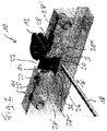
- FIGS. 1 to 4 show a schematic representation of an exemplary embodiment of an integrated drive 10 according to the invention for opening and closing a window.
- a drive can also be provided for opening and closing a door or the like.
- the drive 10 comprises a motorized drive unit that can be integrated in the profile of the window frame, which, to actuate the window sash, interacts with a force transmission element that is rigid on one side, such as a chain or the like, which is provided with an end piece 12 at its end that can be connected to the sash, which is located in a Wing profile integrable power transmission element block 14 can be fixed.
- a force transmission element that is rigid on one side, such as a chain or the like, which is provided with an end piece 12 at its end that can be connected to the sash, which is located in a Wing profile integrable power transmission element block 14 can be fixed.
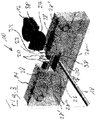
- the end piece 12 of the force transmission element can be fixed in the force transmission element bracket 14 via a latching connection 16 and the force transmission element bracket 14 is designed in such a way that the end piece 12 of the force transmission element can normally be used both for motorized opening and closing of the sash and when the sash is closed by the Latch connection 16 can be fixed in the force transmission element block 14 and the latch connection 16 can be released manually from the outside for emergencies when the wing is closed by applying a pressing force F using a tool 18 that can be guided through an opening provided in the wing profile in order to release the end piece 12 of the force transmission element.
- a screwdriver or the like can be used as the tool 18 , for example.
- the locking connection 16 comprises two opposite bolts 20, each mounted axially displaceably in the force transmission element bracket 14, which extend from opposite sides into a receiving area 22 of the force transmission element bracket 14 for the end piece 12 of the force transmission element, resiliently biased towards one another and for Fixing the end piece 12 of the force transmission element in the receiving area 22 from the two opposite sides in an opening 24 of the end piece 12 of the force transmission element can be latched.
- the end piece 12 of the power transmission element can be provided with a through opening 24 into which the two bolts 20 of opposite Ends are snapped forth.
- the end piece 12 of the force transmission element is provided on opposite sides with a separate opening 24 in each of which a bolt 20 can be latched.
- the force transmission element block 14 is provided with a release mechanism 26, via which, with a respective application of a pressing force F applied by means of the tool 18, the spring-biased bolts 20 towards each other to release the latching connection 16 and to release the end piece 12 of the force transmission element against the spring forces can be pressed apart.
- the release mechanism 26 of the force-transmitting element block 14 comprises two opposing bearing elements 28, each mounted axially displaceably in the force-transmitting element block 14, resiliently preloaded towards one another and laterally delimiting the receiving area 22, on each of which one of the two bolts 20 is firmly supported is and via which the bolts 20 are resiliently biased toward one another.
- the release mechanism 26 in the present case also comprises an intermediate piece 30 which is arranged between the two bearing elements 28 which are resiliently biased towards one another, can be displaced perpendicularly to the bearing elements 28 and can be acted upon by the tool 18 and which interacts with complementary inclined surfaces 32 of the bearing elements 28 Has inclined surfaces 34, which cause the two bearing elements 28 and thus the two bolts 20 to loosen the Locking connection 16 and to release the end piece 12 of the power transmission element are pressed apart.
- the two bearing elements 28 are each designed as angles and the bolts 20 are firmly supported on opposing first legs 28' of the angle-like bearing elements 28, while the intermediate piece 30 between the first legs 28' at least substantially perpendicular second legs 28" of the bearing elements 28.
- the inclined surfaces 32 of the bearing elements 28 which interact with the complementary inclined surfaces 34 of the intermediate bearing piece 30 are provided on their second legs 28".
- the end piece 12 of the force transmission element has on opposite sides with complementary inclined surfaces 36 of the bolts 20 interacting inclined surfaces 38, so that when the end piece 12 of the force transmission element is inserted into the force transmission element block 14, the two bolts 20 are initially pressed apart against the spring forces acting on them be, in order to then snap into the end piece 12 of the force transmission element by the spring forces.
- FIG 1 shows the integrated drive 10 with the window closed and the bolt 20 locked with the power transmission element block 14.
- the two bolts 20 are pulled out of the force-transmitting element block 14 by the pressing force F applied by means of the tool 18 in order to release the end piece 12 of the force-transmitting element.
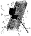
- 3 shows the integrated drive 10 in a phase in which, after the end piece 12 of the force transmission element has been removed, the bolts 20 are moved back towards one another into their starting position by the spring forces when the tool 18 is pulled out.
- connection between the end piece 12 of the power transmission element and the power transmission element bracket 14 and accordingly the connection between the sash and frame of the window in an emergency or in the event of a failure of the motorized drive unit is simple and reliable with minimal effort To avoid damaging the window, it can be released manually from the outside.
Landscapes
- Power-Operated Mechanisms For Wings (AREA)
- Valve Device For Special Equipments (AREA)
- Valve-Gear Or Valve Arrangements (AREA)
- Surgical Instruments (AREA)
Applications Claiming Priority (1)
| Application Number | Priority Date | Filing Date | Title |
|---|---|---|---|
| DE102019205552.4A DE102019205552B3 (de) | 2019-04-17 | 2019-04-17 | Antrieb zum Öffnen und Schließen eines Flügels eines Fensters oder einer Tür |
Publications (2)
| Publication Number | Publication Date |
|---|---|
| EP3725992A1 EP3725992A1 (de) | 2020-10-21 |
| EP3725992B1 true EP3725992B1 (de) | 2022-06-15 |
Family
ID=69770725
Family Applications (1)
| Application Number | Title | Priority Date | Filing Date |
|---|---|---|---|
| EP20161103.5A Active EP3725992B1 (de) | 2019-04-17 | 2020-03-05 | Antrieb |
Country Status (4)
| Country | Link |
|---|---|
| EP (1) | EP3725992B1 (pl) |
| DE (1) | DE102019205552B3 (pl) |
| ES (1) | ES2925661T3 (pl) |
| PL (1) | PL3725992T3 (pl) |
Families Citing this family (1)
| Publication number | Priority date | Publication date | Assignee | Title |
|---|---|---|---|---|
| CN117916442A (zh) * | 2021-06-28 | 2024-04-19 | 亚萨合莱新西兰有限公司 | 致动器 |
Family Cites Families (5)
| Publication number | Priority date | Publication date | Assignee | Title |
|---|---|---|---|---|
| DE19858533A1 (de) * | 1997-12-18 | 1999-08-12 | Steinel Ag | Betätigungsvorrichtung für einen Tür- oder Fensterflügel |
| ITTV20040009U1 (it) * | 2004-02-19 | 2004-05-19 | Nekos Srl | Aggancio tra un azionamento per infissi e l'infisso stesso |
| DE102004031212B3 (de) | 2004-06-28 | 2005-06-30 | Geze Gmbh | Flügel in einem Blendrahmen mit einem Antrieb |
| DE102006013332A1 (de) | 2006-03-21 | 2007-09-27 | SCHÜCO International KG | Fenster- oder Türelement mit einem automatischen Antrieb |
| DE202010000269U1 (de) * | 2010-02-26 | 2011-08-23 | Stg-Beikirch Industrieelektronik + Sicherheitstechnik Gmbh & Co. Kg | Lagerbock und Ausstelleinrichtung |
-
2019
- 2019-04-17 DE DE102019205552.4A patent/DE102019205552B3/de active Active
-
2020
- 2020-03-05 EP EP20161103.5A patent/EP3725992B1/de active Active
- 2020-03-05 PL PL20161103.5T patent/PL3725992T3/pl unknown
- 2020-03-05 ES ES20161103T patent/ES2925661T3/es active Active
Also Published As
| Publication number | Publication date |
|---|---|
| EP3725992A1 (de) | 2020-10-21 |
| DE102019205552B3 (de) | 2020-06-04 |
| PL3725992T3 (pl) | 2022-10-17 |
| ES2925661T3 (es) | 2022-10-19 |
Similar Documents
| Publication | Publication Date | Title |
|---|---|---|
| EP1460211A2 (de) | Kraftfahrzeugschloss | |
| EP3277899B1 (de) | Türgriffanordnung für ein kraftfahrzeug | |
| EP3725992B1 (de) | Antrieb | |
| EP0444405A2 (de) | Beschlag für Fenster und Türen | |
| DE10040593A1 (de) | Verriegelungseinrichtung für längsverstellbare Sitze, insbesondere Kraftfahrzeugsitze | |
| DE19923487B4 (de) | Widerlager mit Formteil zum Befestigen von Betätigungszügen | |
| DE202004011539U1 (de) | Band für Türen, Fenster u.dgl. | |
| EP2317047B1 (de) | Beschlaganordnung | |
| EP3348776B1 (de) | Befestigung eines fingerschutzrollos zur spaltüberdeckung | |
| DE4032677C2 (de) | Automatische Türanlage mit motorisch angetriebenen Flügeln | |
| EP1179110A1 (de) | Riegelstangenbeschlag für ein fenster oder eine tür | |
| DE3151224A1 (de) | Vorrichtung zur befestigung eines getriebes an einem rahmen von fenstern, tueren oder dergleichen | |
| DE102024203222B3 (de) | Beschlaganordnung für ein Fenster, eine Tür oder dergleichen zur Betätigung einer Feststellbremse | |
| DE102005056151A1 (de) | Ecklageranordnung für Fenster, Türen oder dergleichen | |
| EP4479613B1 (de) | Verriegelungsvorrichtung, türanordnung mit einer solchen verriegelungsvorrichtung und verfahren zur montage einer solchen verriegelungseinrichtung | |
| DE7630475U1 (de) | Vorrichtung zum oeffnen und schliessen von toren | |
| EP3854967B1 (de) | Treibstangenbeschlag für einen nebenflügel eines zweiflügeligen fensters | |
| DE102014111131A1 (de) | Vorrichtung zur Ver- und Entriegelung eines Fensterflügels, einer Lüftungsklappe oder dergleichen an einem Blendrahmen | |
| EP2085543B1 (de) | Schloss | |
| DE4230476A1 (de) | Fenster- oder Türbeschlag | |
| EP3913171B1 (de) | Verriegelungs- und/oder positionierantrieb für ein fenster, eine tür oder dergleichen | |
| DE102019117867A1 (de) | Verschluss mit einem verstärkten gehäuse für ein fenster, eine tür oder dergleichen | |
| DE2042936A1 (de) | Schwenkschiebetuer fuer fahrzeuge. | |
| DE19809900B4 (de) | Vorrichtung zur Sicherung von Fenster, Fenstertüren und Türen gegen gewaltsames Öffnen | |
| EP3287577A1 (de) | Schliessvorrichtung für eine tür, ein fenster oder dergleichen |
Legal Events
| Date | Code | Title | Description |
|---|---|---|---|
| PUAI | Public reference made under article 153(3) epc to a published international application that has entered the european phase |
Free format text: ORIGINAL CODE: 0009012 |
|
| STAA | Information on the status of an ep patent application or granted ep patent |
Free format text: STATUS: THE APPLICATION HAS BEEN PUBLISHED |
|
| AK | Designated contracting states |
Kind code of ref document: A1 Designated state(s): AL AT BE BG CH CY CZ DE DK EE ES FI FR GB GR HR HU IE IS IT LI LT LU LV MC MK MT NL NO PL PT RO RS SE SI SK SM TR |
|
| AX | Request for extension of the european patent |
Extension state: BA ME |
|
| STAA | Information on the status of an ep patent application or granted ep patent |
Free format text: STATUS: REQUEST FOR EXAMINATION WAS MADE |
|
| 17P | Request for examination filed |
Effective date: 20210218 |
|
| RBV | Designated contracting states (corrected) |
Designated state(s): AL AT BE BG CH CY CZ DE DK EE ES FI FR GB GR HR HU IE IS IT LI LT LU LV MC MK MT NL NO PL PT RO RS SE SI SK SM TR |
|
| RIC1 | Information provided on ipc code assigned before grant |
Ipc: E05F 11/04 20060101ALI20211119BHEP Ipc: E05F 15/627 20150101AFI20211119BHEP |
|
| GRAP | Despatch of communication of intention to grant a patent |
Free format text: ORIGINAL CODE: EPIDOSNIGR1 |
|
| STAA | Information on the status of an ep patent application or granted ep patent |
Free format text: STATUS: GRANT OF PATENT IS INTENDED |
|
| INTG | Intention to grant announced |
Effective date: 20220107 |
|
| RIN1 | Information on inventor provided before grant (corrected) |
Inventor name: STROBEL, FABIAN |
|
| GRAS | Grant fee paid |
Free format text: ORIGINAL CODE: EPIDOSNIGR3 |
|
| GRAA | (expected) grant |
Free format text: ORIGINAL CODE: 0009210 |
|
| STAA | Information on the status of an ep patent application or granted ep patent |
Free format text: STATUS: THE PATENT HAS BEEN GRANTED |
|
| AK | Designated contracting states |
Kind code of ref document: B1 Designated state(s): AL AT BE BG CH CY CZ DE DK EE ES FI FR GB GR HR HU IE IS IT LI LT LU LV MC MK MT NL NO PL PT RO RS SE SI SK SM TR |
|
| REG | Reference to a national code |
Ref country code: CH Ref legal event code: EP Ref country code: GB Ref legal event code: FG4D Free format text: NOT ENGLISH |
|
| REG | Reference to a national code |
Ref country code: IE Ref legal event code: FG4D Free format text: LANGUAGE OF EP DOCUMENT: GERMAN |
|
| REG | Reference to a national code |
Ref country code: DE Ref legal event code: R096 Ref document number: 502020001225 Country of ref document: DE |
|
| REG | Reference to a national code |
Ref country code: AT Ref legal event code: REF Ref document number: 1498510 Country of ref document: AT Kind code of ref document: T Effective date: 20220715 |
|
| REG | Reference to a national code |
Ref country code: LT Ref legal event code: MG9D |
|
| REG | Reference to a national code |
Ref country code: NL Ref legal event code: MP Effective date: 20220615 Ref country code: ES Ref legal event code: FG2A Ref document number: 2925661 Country of ref document: ES Kind code of ref document: T3 Effective date: 20221019 |
|
| PG25 | Lapsed in a contracting state [announced via postgrant information from national office to epo] |
Ref country code: SE Free format text: LAPSE BECAUSE OF FAILURE TO SUBMIT A TRANSLATION OF THE DESCRIPTION OR TO PAY THE FEE WITHIN THE PRESCRIBED TIME-LIMIT Effective date: 20220615 Ref country code: NO Free format text: LAPSE BECAUSE OF FAILURE TO SUBMIT A TRANSLATION OF THE DESCRIPTION OR TO PAY THE FEE WITHIN THE PRESCRIBED TIME-LIMIT Effective date: 20220915 Ref country code: LT Free format text: LAPSE BECAUSE OF FAILURE TO SUBMIT A TRANSLATION OF THE DESCRIPTION OR TO PAY THE FEE WITHIN THE PRESCRIBED TIME-LIMIT Effective date: 20220615 Ref country code: HR Free format text: LAPSE BECAUSE OF FAILURE TO SUBMIT A TRANSLATION OF THE DESCRIPTION OR TO PAY THE FEE WITHIN THE PRESCRIBED TIME-LIMIT Effective date: 20220615 Ref country code: GR Free format text: LAPSE BECAUSE OF FAILURE TO SUBMIT A TRANSLATION OF THE DESCRIPTION OR TO PAY THE FEE WITHIN THE PRESCRIBED TIME-LIMIT Effective date: 20220916 Ref country code: FI Free format text: LAPSE BECAUSE OF FAILURE TO SUBMIT A TRANSLATION OF THE DESCRIPTION OR TO PAY THE FEE WITHIN THE PRESCRIBED TIME-LIMIT Effective date: 20220615 Ref country code: BG Free format text: LAPSE BECAUSE OF FAILURE TO SUBMIT A TRANSLATION OF THE DESCRIPTION OR TO PAY THE FEE WITHIN THE PRESCRIBED TIME-LIMIT Effective date: 20220915 |
|
| PG25 | Lapsed in a contracting state [announced via postgrant information from national office to epo] |
Ref country code: RS Free format text: LAPSE BECAUSE OF FAILURE TO SUBMIT A TRANSLATION OF THE DESCRIPTION OR TO PAY THE FEE WITHIN THE PRESCRIBED TIME-LIMIT Effective date: 20220615 Ref country code: LV Free format text: LAPSE BECAUSE OF FAILURE TO SUBMIT A TRANSLATION OF THE DESCRIPTION OR TO PAY THE FEE WITHIN THE PRESCRIBED TIME-LIMIT Effective date: 20220615 |
|
| PG25 | Lapsed in a contracting state [announced via postgrant information from national office to epo] |
Ref country code: NL Free format text: LAPSE BECAUSE OF FAILURE TO SUBMIT A TRANSLATION OF THE DESCRIPTION OR TO PAY THE FEE WITHIN THE PRESCRIBED TIME-LIMIT Effective date: 20220615 |
|
| PG25 | Lapsed in a contracting state [announced via postgrant information from national office to epo] |
Ref country code: SM Free format text: LAPSE BECAUSE OF FAILURE TO SUBMIT A TRANSLATION OF THE DESCRIPTION OR TO PAY THE FEE WITHIN THE PRESCRIBED TIME-LIMIT Effective date: 20220615 Ref country code: SK Free format text: LAPSE BECAUSE OF FAILURE TO SUBMIT A TRANSLATION OF THE DESCRIPTION OR TO PAY THE FEE WITHIN THE PRESCRIBED TIME-LIMIT Effective date: 20220615 Ref country code: RO Free format text: LAPSE BECAUSE OF FAILURE TO SUBMIT A TRANSLATION OF THE DESCRIPTION OR TO PAY THE FEE WITHIN THE PRESCRIBED TIME-LIMIT Effective date: 20220615 Ref country code: PT Free format text: LAPSE BECAUSE OF FAILURE TO SUBMIT A TRANSLATION OF THE DESCRIPTION OR TO PAY THE FEE WITHIN THE PRESCRIBED TIME-LIMIT Effective date: 20221017 Ref country code: EE Free format text: LAPSE BECAUSE OF FAILURE TO SUBMIT A TRANSLATION OF THE DESCRIPTION OR TO PAY THE FEE WITHIN THE PRESCRIBED TIME-LIMIT Effective date: 20220615 Ref country code: CZ Free format text: LAPSE BECAUSE OF FAILURE TO SUBMIT A TRANSLATION OF THE DESCRIPTION OR TO PAY THE FEE WITHIN THE PRESCRIBED TIME-LIMIT Effective date: 20220615 |
|
| PG25 | Lapsed in a contracting state [announced via postgrant information from national office to epo] |
Ref country code: IS Free format text: LAPSE BECAUSE OF FAILURE TO SUBMIT A TRANSLATION OF THE DESCRIPTION OR TO PAY THE FEE WITHIN THE PRESCRIBED TIME-LIMIT Effective date: 20221015 |
|
| REG | Reference to a national code |
Ref country code: DE Ref legal event code: R097 Ref document number: 502020001225 Country of ref document: DE |
|
| PG25 | Lapsed in a contracting state [announced via postgrant information from national office to epo] |
Ref country code: AL Free format text: LAPSE BECAUSE OF FAILURE TO SUBMIT A TRANSLATION OF THE DESCRIPTION OR TO PAY THE FEE WITHIN THE PRESCRIBED TIME-LIMIT Effective date: 20220615 |
|
| PLBE | No opposition filed within time limit |
Free format text: ORIGINAL CODE: 0009261 |
|
| STAA | Information on the status of an ep patent application or granted ep patent |
Free format text: STATUS: NO OPPOSITION FILED WITHIN TIME LIMIT |
|
| PG25 | Lapsed in a contracting state [announced via postgrant information from national office to epo] |
Ref country code: DK Free format text: LAPSE BECAUSE OF FAILURE TO SUBMIT A TRANSLATION OF THE DESCRIPTION OR TO PAY THE FEE WITHIN THE PRESCRIBED TIME-LIMIT Effective date: 20220615 |
|
| 26N | No opposition filed |
Effective date: 20230316 |
|
| PG25 | Lapsed in a contracting state [announced via postgrant information from national office to epo] |
Ref country code: SI Free format text: LAPSE BECAUSE OF FAILURE TO SUBMIT A TRANSLATION OF THE DESCRIPTION OR TO PAY THE FEE WITHIN THE PRESCRIBED TIME-LIMIT Effective date: 20220615 |
|
| P01 | Opt-out of the competence of the unified patent court (upc) registered |
Effective date: 20230510 |
|
| PG25 | Lapsed in a contracting state [announced via postgrant information from national office to epo] |
Ref country code: MC Free format text: LAPSE BECAUSE OF FAILURE TO SUBMIT A TRANSLATION OF THE DESCRIPTION OR TO PAY THE FEE WITHIN THE PRESCRIBED TIME-LIMIT Effective date: 20220615 |
|
| REG | Reference to a national code |
Ref country code: BE Ref legal event code: MM Effective date: 20230331 |
|
| PG25 | Lapsed in a contracting state [announced via postgrant information from national office to epo] |
Ref country code: LU Free format text: LAPSE BECAUSE OF NON-PAYMENT OF DUE FEES Effective date: 20230305 |
|
| REG | Reference to a national code |
Ref country code: IE Ref legal event code: MM4A |
|
| PG25 | Lapsed in a contracting state [announced via postgrant information from national office to epo] |
Ref country code: IE Free format text: LAPSE BECAUSE OF NON-PAYMENT OF DUE FEES Effective date: 20230305 |
|
| PG25 | Lapsed in a contracting state [announced via postgrant information from national office to epo] |
Ref country code: BE Free format text: LAPSE BECAUSE OF NON-PAYMENT OF DUE FEES Effective date: 20230331 |
|
| PG25 | Lapsed in a contracting state [announced via postgrant information from national office to epo] |
Ref country code: BG Free format text: LAPSE BECAUSE OF FAILURE TO SUBMIT A TRANSLATION OF THE DESCRIPTION OR TO PAY THE FEE WITHIN THE PRESCRIBED TIME-LIMIT Effective date: 20220615 |
|
| PG25 | Lapsed in a contracting state [announced via postgrant information from national office to epo] |
Ref country code: BG Free format text: LAPSE BECAUSE OF FAILURE TO SUBMIT A TRANSLATION OF THE DESCRIPTION OR TO PAY THE FEE WITHIN THE PRESCRIBED TIME-LIMIT Effective date: 20220615 |
|
| PGFP | Annual fee paid to national office [announced via postgrant information from national office to epo] |
Ref country code: DE Payment date: 20250331 Year of fee payment: 6 |
|
| PGFP | Annual fee paid to national office [announced via postgrant information from national office to epo] |
Ref country code: AT Payment date: 20250320 Year of fee payment: 6 |
|
| PGFP | Annual fee paid to national office [announced via postgrant information from national office to epo] |
Ref country code: FR Payment date: 20250326 Year of fee payment: 6 Ref country code: PL Payment date: 20250225 Year of fee payment: 6 |
|
| PGFP | Annual fee paid to national office [announced via postgrant information from national office to epo] |
Ref country code: IT Payment date: 20250325 Year of fee payment: 6 Ref country code: GB Payment date: 20250324 Year of fee payment: 6 |
|
| PGFP | Annual fee paid to national office [announced via postgrant information from national office to epo] |
Ref country code: ES Payment date: 20250429 Year of fee payment: 6 |
|
| PGFP | Annual fee paid to national office [announced via postgrant information from national office to epo] |
Ref country code: CH Payment date: 20250401 Year of fee payment: 6 |
|
| PG25 | Lapsed in a contracting state [announced via postgrant information from national office to epo] |
Ref country code: CY Free format text: LAPSE BECAUSE OF FAILURE TO SUBMIT A TRANSLATION OF THE DESCRIPTION OR TO PAY THE FEE WITHIN THE PRESCRIBED TIME-LIMIT; INVALID AB INITIO Effective date: 20200305 |
|
| PG25 | Lapsed in a contracting state [announced via postgrant information from national office to epo] |
Ref country code: HU Free format text: LAPSE BECAUSE OF FAILURE TO SUBMIT A TRANSLATION OF THE DESCRIPTION OR TO PAY THE FEE WITHIN THE PRESCRIBED TIME-LIMIT; INVALID AB INITIO Effective date: 20200305 |
|
| PG25 | Lapsed in a contracting state [announced via postgrant information from national office to epo] |
Ref country code: TR Free format text: LAPSE BECAUSE OF FAILURE TO SUBMIT A TRANSLATION OF THE DESCRIPTION OR TO PAY THE FEE WITHIN THE PRESCRIBED TIME-LIMIT Effective date: 20220615 |