EP3725945B1 - Verfahren zur herstellung einer dreidimensionalen textur auf einem kunststoffboden - Google Patents
Verfahren zur herstellung einer dreidimensionalen textur auf einem kunststoffboden Download PDFInfo
- Publication number
- EP3725945B1 EP3725945B1 EP19886428.2A EP19886428A EP3725945B1 EP 3725945 B1 EP3725945 B1 EP 3725945B1 EP 19886428 A EP19886428 A EP 19886428A EP 3725945 B1 EP3725945 B1 EP 3725945B1
- Authority
- EP
- European Patent Office
- Prior art keywords
- pattern
- forming
- stereoscopic
- base board
- raw material
- Prior art date
- Legal status (The legal status is an assumption and is not a legal conclusion. Google has not performed a legal analysis and makes no representation as to the accuracy of the status listed.)
- Active
Links
Images


Classifications
-
- B—PERFORMING OPERATIONS; TRANSPORTING
- B32—LAYERED PRODUCTS
- B32B—LAYERED PRODUCTS, i.e. PRODUCTS BUILT-UP OF STRATA OF FLAT OR NON-FLAT, e.g. CELLULAR OR HONEYCOMB, FORM
- B32B33/00—Layered products characterised by particular properties or particular surface features, e.g. particular surface coatings; Layered products designed for particular purposes not covered by another single class
-
- E—FIXED CONSTRUCTIONS
- E01—CONSTRUCTION OF ROADS, RAILWAYS, OR BRIDGES
- E01C—CONSTRUCTION OF, OR SURFACES FOR, ROADS, SPORTS GROUNDS, OR THE LIKE; MACHINES OR AUXILIARY TOOLS FOR CONSTRUCTION OR REPAIR
- E01C23/00—Auxiliary devices or arrangements for constructing, repairing, reconditioning, or taking-up road or like surfaces
- E01C23/06—Devices or arrangements for working the finished surface; Devices for repairing or reconditioning the surface of damaged paving; Recycling in place or on the road
- E01C23/08—Devices or arrangements for working the finished surface; Devices for repairing or reconditioning the surface of damaged paving; Recycling in place or on the road for roughening or patterning; for removing the surface down to a predetermined depth high spots or material bonded to the surface, e.g. markings; for maintaining earth roads, clay courts or like surfaces by means of surface working tools, e.g. scarifiers, levelling blades
-
- B—PERFORMING OPERATIONS; TRANSPORTING
- B05—SPRAYING OR ATOMISING IN GENERAL; APPLYING FLUENT MATERIALS TO SURFACES, IN GENERAL
- B05D—PROCESSES FOR APPLYING FLUENT MATERIALS TO SURFACES, IN GENERAL
- B05D5/00—Processes for applying liquids or other fluent materials to surfaces to obtain special surface effects, finishes or structures
-
- B—PERFORMING OPERATIONS; TRANSPORTING
- B29—WORKING OF PLASTICS; WORKING OF SUBSTANCES IN A PLASTIC STATE IN GENERAL
- B29C—SHAPING OR JOINING OF PLASTICS; SHAPING OF MATERIAL IN A PLASTIC STATE, NOT OTHERWISE PROVIDED FOR; AFTER-TREATMENT OF THE SHAPED PRODUCTS, e.g. REPAIRING
- B29C59/00—Surface shaping of articles, e.g. embossing; Apparatus therefor
- B29C59/02—Surface shaping of articles, e.g. embossing; Apparatus therefor by mechanical means, e.g. pressing
- B29C59/026—Surface shaping of articles, e.g. embossing; Apparatus therefor by mechanical means, e.g. pressing of layered or coated substantially flat surfaces
-
- B—PERFORMING OPERATIONS; TRANSPORTING
- B32—LAYERED PRODUCTS
- B32B—LAYERED PRODUCTS, i.e. PRODUCTS BUILT-UP OF STRATA OF FLAT OR NON-FLAT, e.g. CELLULAR OR HONEYCOMB, FORM
- B32B37/00—Methods or apparatus for laminating, e.g. by curing or by ultrasonic bonding
- B32B37/10—Methods or apparatus for laminating, e.g. by curing or by ultrasonic bonding characterised by the pressing technique, e.g. using action of vacuum or fluid pressure
-
- B—PERFORMING OPERATIONS; TRANSPORTING
- B32—LAYERED PRODUCTS
- B32B—LAYERED PRODUCTS, i.e. PRODUCTS BUILT-UP OF STRATA OF FLAT OR NON-FLAT, e.g. CELLULAR OR HONEYCOMB, FORM
- B32B37/00—Methods or apparatus for laminating, e.g. by curing or by ultrasonic bonding
- B32B37/14—Methods or apparatus for laminating, e.g. by curing or by ultrasonic bonding characterised by the properties of the layers
- B32B37/24—Methods or apparatus for laminating, e.g. by curing or by ultrasonic bonding characterised by the properties of the layers with at least one layer not being coherent before laminating, e.g. made up from granular material sprinkled onto a substrate
-
- B—PERFORMING OPERATIONS; TRANSPORTING
- B32—LAYERED PRODUCTS
- B32B—LAYERED PRODUCTS, i.e. PRODUCTS BUILT-UP OF STRATA OF FLAT OR NON-FLAT, e.g. CELLULAR OR HONEYCOMB, FORM
- B32B38/00—Ancillary operations in connection with laminating processes
- B32B38/14—Printing or colouring
- B32B38/145—Printing
-
- B—PERFORMING OPERATIONS; TRANSPORTING
- B41—PRINTING; LINING MACHINES; TYPEWRITERS; STAMPS
- B41M—PRINTING, DUPLICATING, MARKING, OR COPYING PROCESSES; COLOUR PRINTING
- B41M7/00—After-treatment of prints, e.g. heating, irradiating, setting of the ink, protection of the printed stock
- B41M7/0036—After-treatment of prints, e.g. heating, irradiating, setting of the ink, protection of the printed stock using protective coatings or layers dried without curing
-
- B—PERFORMING OPERATIONS; TRANSPORTING
- B41—PRINTING; LINING MACHINES; TYPEWRITERS; STAMPS
- B41M—PRINTING, DUPLICATING, MARKING, OR COPYING PROCESSES; COLOUR PRINTING
- B41M7/00—After-treatment of prints, e.g. heating, irradiating, setting of the ink, protection of the printed stock
- B41M7/0045—After-treatment of prints, e.g. heating, irradiating, setting of the ink, protection of the printed stock using protective coatings or film forming compositions cured by mechanical wave energy, e.g. ultrasonics, cured by electromagnetic radiation or waves, e.g. ultraviolet radiation, electron beams, or cured by magnetic or electric fields, e.g. electric discharge, plasma
-
- E—FIXED CONSTRUCTIONS
- E04—BUILDING
- E04F—FINISHING WORK ON BUILDINGS, e.g. STAIRS, FLOORS
- E04F15/00—Flooring
- E04F15/02—Flooring or floor layers composed of a number of similar elements
-
- G—PHYSICS
- G03—PHOTOGRAPHY; CINEMATOGRAPHY; ANALOGOUS TECHNIQUES USING WAVES OTHER THAN OPTICAL WAVES; ELECTROGRAPHY; HOLOGRAPHY
- G03F—PHOTOMECHANICAL PRODUCTION OF TEXTURED OR PATTERNED SURFACES, e.g. FOR PRINTING, FOR PROCESSING OF SEMICONDUCTOR DEVICES; MATERIALS THEREFOR; ORIGINALS THEREFOR; APPARATUS SPECIALLY ADAPTED THEREFOR
- G03F7/00—Photomechanical, e.g. photolithographic, production of textured or patterned surfaces, e.g. printing surfaces; Materials therefor, e.g. comprising photoresists; Apparatus specially adapted therefor
- G03F7/0002—Lithographic processes using patterning methods other than those involving the exposure to radiation, e.g. by stamping
-
- B—PERFORMING OPERATIONS; TRANSPORTING
- B41—PRINTING; LINING MACHINES; TYPEWRITERS; STAMPS
- B41M—PRINTING, DUPLICATING, MARKING, OR COPYING PROCESSES; COLOUR PRINTING
- B41M3/00—Printing processes to produce particular kinds of printed work, e.g. patterns
- B41M3/06—Veined printings; Fluorescent printings; Stereoscopic images; Imitated patterns, e.g. tissues, textiles
-
- B—PERFORMING OPERATIONS; TRANSPORTING
- B41—PRINTING; LINING MACHINES; TYPEWRITERS; STAMPS
- B41M—PRINTING, DUPLICATING, MARKING, OR COPYING PROCESSES; COLOUR PRINTING
- B41M5/00—Duplicating or marking methods; Sheet materials for use therein
- B41M5/0041—Digital printing on surfaces other than ordinary paper
- B41M5/0047—Digital printing on surfaces other than ordinary paper by ink-jet printing
-
- B—PERFORMING OPERATIONS; TRANSPORTING
- B41—PRINTING; LINING MACHINES; TYPEWRITERS; STAMPS
- B41M—PRINTING, DUPLICATING, MARKING, OR COPYING PROCESSES; COLOUR PRINTING
- B41M5/00—Duplicating or marking methods; Sheet materials for use therein
- B41M5/0041—Digital printing on surfaces other than ordinary paper
- B41M5/0064—Digital printing on surfaces other than ordinary paper on plastics, horn, rubber, or other organic polymers
-
- B—PERFORMING OPERATIONS; TRANSPORTING
- B41—PRINTING; LINING MACHINES; TYPEWRITERS; STAMPS
- B41M—PRINTING, DUPLICATING, MARKING, OR COPYING PROCESSES; COLOUR PRINTING
- B41M7/00—After-treatment of prints, e.g. heating, irradiating, setting of the ink, protection of the printed stock
- B41M7/0027—After-treatment of prints, e.g. heating, irradiating, setting of the ink, protection of the printed stock using protective coatings or layers by lamination or by fusion of the coatings or layers
-
- E—FIXED CONSTRUCTIONS
- E04—BUILDING
- E04F—FINISHING WORK ON BUILDINGS, e.g. STAIRS, FLOORS
- E04F15/00—Flooring
- E04F15/02—Flooring or floor layers composed of a number of similar elements
- E04F15/10—Flooring or floor layers composed of a number of similar elements of other materials, e.g. fibrous or chipped materials, organic plastics, magnesite tiles, hardboard, or with a top layer of other materials
- E04F15/105—Flooring or floor layers composed of a number of similar elements of other materials, e.g. fibrous or chipped materials, organic plastics, magnesite tiles, hardboard, or with a top layer of other materials of organic plastics with or without reinforcements or filling materials
-
- E—FIXED CONSTRUCTIONS
- E04—BUILDING
- E04F—FINISHING WORK ON BUILDINGS, e.g. STAIRS, FLOORS
- E04F15/00—Flooring
- E04F15/02—Flooring or floor layers composed of a number of similar elements
- E04F15/10—Flooring or floor layers composed of a number of similar elements of other materials, e.g. fibrous or chipped materials, organic plastics, magnesite tiles, hardboard, or with a top layer of other materials
- E04F15/107—Flooring or floor layers composed of a number of similar elements of other materials, e.g. fibrous or chipped materials, organic plastics, magnesite tiles, hardboard, or with a top layer of other materials composed of several layers, e.g. sandwich panels
Definitions
- This disclosure generally relates to the technical field of floor boards, and more particularly, to a method for forming stereoscopic patterns of plastic floor boards.
- the purpose of the present disclosure is to provide a method for forming stereoscopic patterns of plastic floor boards, which designs and forms various patterns according to users' needs, makes the stereoscopic patterns more aesthetically appealing, improves the production efficiency and ensures the stability of quality.
- a first aspect of the present invention is set out in independent claim 1.
- Optional features are as disclosed in dependent claims 2 to 8.
- the present disclosure has the following advantages: through adopting the method of the present disclosure, various patterns may be designed and formed according to users' needs, the stereoscopic patterns become more aesthetically appealing, the production efficiency is improved and the stability of quality is ensured.
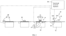
- a method for forming stereoscopic patterns of plastic floor boards comprises machinery equipment including at least one digital printing unit 10, a first forming unit 20 and a second forming unit 30, wherein the aforesaid equipment is utilized to perform a series of processes to a base board 40, thereby forming the stereoscopic pattern of the plastic floor board.
- the aforesaid forming method comprising the steps of: Step A: taking a base board 40, wherein the base board is normally used as the bottom material of a plastic floor board, has a blank or plain outer surface 41, and may be continuously extrusion-formed using an extruder or cut into individual boards after machine forming.
- Step B digital printing: positioning the base board 40 on the digital printing unit 10, and printing a pattern layer 42 on the base board 40, wherein the digital printing unit 10 comprises a first machine body 11, a first conveying platform 12 arranged on the first machine body 11, and a printing mechanism 13 correspondingly arranged above the first conveying platform 12, wherein the printing mechanism 13 comprises a collecting seat 131, one end of the collecting seat 131 is connected to a source for supplying the pigment, and the other end of the collecting seat 131 is provided with a discharging portion 132 for discharging the pigment, wherein the printing mechanism 13 may be controlled by an electrical control system 50, wherein a sensing unit 133 is arranged at a proper position, and the sensing unit 133 is electrically connected to the electrical control system 50.
- the digital printing unit 10 comprises a first machine body 11, a first conveying platform 12 arranged on the first machine body 11, and a printing mechanism 13 correspondingly arranged above the first conveying platform 12, wherein the printing mechanism 13 comprises a collecting seat 131, one end of
- the electrical control system 50 receives a signal from the sensing unit 133, and the printing mechanism 13 is controlled to print the pigment on the outer surface 41 of the base board 40 through the discharging portion 132 according to the pattern preset in the electrical control system 50.
- a pattern layer 42 is formed.
- step B may be repeated for 2-3 times to achieve a pattern layer with a specific height.
- Step C forming a protection layer 43: forming a protection layer 43 on the pattern layer 42 using a transparent melt plastic raw material by the first forming unit 20, wherein the plastic material used as the protection layer may be a UV coating, a PVC material or a PUR coating.
- the first forming unit 20 comprises a second machine body 21, a second conveying platform 22 arranged on the second machine body 21, and a coating mechanism 23 correspondingly arranged above the second conveying platform 22, wherein the second conveying platform 22 further comprises two conveying wheels 221, a plurality of rolling wheels 222 and a conveying belt 223, wherein the coating mechanism 23 comprises a main roll 231 and an auxiliary roll 232, and a receiving portion 233 is arranged between the two rolls for receiving the melt plastic raw material.
- the coating mechanism 23 is controlled by the electrical control system 50.
- the melt plastic raw material in the receiving portion 233 is coated on the pattern layer 42 along the rotation of the main roll 231.
- the coating of the melt plastic raw material becomes more uniform.
- the melt plastic raw material may be irradiated by a drying apparatus 61 such as a UV lamp, thus accelerating the drying and hardening of the melt plastic raw material.
- step C may be repeated for 2-3 times to achieve a protection layer with a specific height.
- the first forming unit 20 comprises a third conveying platform 24 arranged on the second machine body 21 and a shower-coating mechanism 25 correspondingly arranged above the third conveying platform 24.
- the third conveying platform 24 comprises a plurality of conveying wheels 241 capable of propelling the conveying belt to rotate.
- the lower end of the shower-coating mechanism 25 is provided with a discharging port 251 whose interior allows the melt plastic raw material to flow therein.
- the melt plastic raw material is vertically discharged from the discharging port 251 in a shower manner.
- the first forming unit 20 may adopt a digital printer (not shown) to form a protection layer by printing.
- Step D forming a stereoscopic pattern 44: forming a stereoscopic pattern 44 on the protection layer 43 by the second forming unit 30, thus forming the plastic floor board with a stereoscopic pattern, wherein the second forming unit 30 may differ in different embodiments.
- the second forming unit 30 may comprise two roll wheels, wherein an embossing pattern 311 having a concave-convex structure is formed on one of the roll wheels 31.
- the concave-convex structure of the embossing pattern 311 is designed to correspond to a particular portion of the pattern layer 42. For instance, when the pattern of the pattern layer 42 is a tree or wood grain, to make a tree burl or the wood grain raise properly, the embossing pattern 311 designed to correspond to the tree burl or wood grain is a recessed structure. According to this design, after the base board 40 passes through the two roll wheels 31 and 32, a stereoscopic pattern 44 with a concave-convex structure is formed on the protection layer 43.
- the second forming unit 30 may be a second coating mechanism 33 arranged on a platform 34, wherein one end of the second coating mechanism 33 is connected to a source for supplying the melt plastic raw material, and the other end of the second coating mechanism 33 outputs the melt plastic raw material.
- the second coating mechanism 33 is controlled by the electrical control system 50. After the protection layer 43 is dried, a stereoscopic pattern 44 with a raised structure is formed on the protection layer 43 through roll-coating or spray-coating.
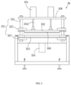
- the second forming unit 30 may be a pressing mechanism, which comprises a mold frame 351.
- An upper mold holder 352, a lower mold holder 353 and two power sources 354 are arranged on the mold frame 351.
- the mold frame 351 comprises a plurality of guide rods 355 penetrating through a positioning plate 356 located above the guide rods 355, and a plurality of connecting plates 357 connected to the upper mold holder 352 and the lower mold holder 353.
- the two power sources 353 are fixedly arranged on the positioning plate 356.
- One end of each power source 354 is provided with a telescopic shaft 3541, and one end of the telescopic shaft 3541 is fixedly connected with the outer surface of the upper mold holder 352.
- the upper mold holder 352 is propelled to move up and down.
- a movable mold plate 358 is arranged on the outer surface of the upper mold holder 352 that corresponds to the lower mold holder 353, and an embossing pattern (not shown) is formed on the outer surface of the mold plate 358.
- the embossing pattern has a concave-convex structure, which is designed to correspond to a particular portion of the pattern layer 42.
- the base board 40 when forming a stereoscopic pattern 44 on the base board 40 using the roll wheels 31-32 or the pressing mechanism, the base board 40 may be positioned at a particular position and a positioning point 45 may be pre-arranged at a proper position on the base board 40, or a plurality of positioning points are arranged on the base board at equal intervals.
- a positioning point 45 is detected by the electrical control system 50, the second forming unit 30 is initiated to form a stereoscopic pattern 44 having a concave-convex structure on the protection layer 43, and each stereoscopic pattern 44 is formed at a particular position on the corresponding pattern layer 42 through positioning the positioning point 45.
- the stereoscopic pattern accurately corresponds to the flat pattern on the pattern layer, achieving an integral stereoscopic visual effect.
- the forming method of the present disclosure allows the patterns of the floor boards to be designed and formed according to users' needs, improves the production efficiency and makes the product quality stable.
- the interior of the upper mold holder 352 and the lower mold holder 353 may be provided with an electric heater to produce heat, or a circulation loop may be installed to guide the hot oil to circulate to produce heat.
- the heating system transmits the heat to the mold plate 358, which enables the movable pressing mechanism to form an embossing pattern through hot-pressing, and to press the plastic floor board materials into a whole.
- cooling water may be supplied to the circulation loops of the upper mold holder 352 and the lower mold holder 353 for cooling.
- the cooled mold plate 358 allows the movable pressing mechanism 30 to form an embossing pattern through cold-pressing, and to presses the plastic floor board materials into a whole.
Landscapes
- Engineering & Computer Science (AREA)
- Architecture (AREA)
- Physics & Mathematics (AREA)
- Mechanical Engineering (AREA)
- Civil Engineering (AREA)
- Structural Engineering (AREA)
- Plasma & Fusion (AREA)
- Electromagnetism (AREA)
- General Physics & Mathematics (AREA)
- Health & Medical Sciences (AREA)
- General Health & Medical Sciences (AREA)
- Textile Engineering (AREA)
- Vascular Medicine (AREA)
- Fluid Mechanics (AREA)
- Mining & Mineral Resources (AREA)
- Application Of Or Painting With Fluid Materials (AREA)
- Floor Finish (AREA)
- Printing Methods (AREA)
- Shaping Of Tube Ends By Bending Or Straightening (AREA)
Claims (8)
- Verfahren zum Formen von stereoskopischen Mustern (44) von Kunststoffbodenbrettern, umfassend die Schritte:Schritt A: Nehmen eines Basisbretts (40), das eine blanke oder schlichte Außenfläche (41) aufweist;Schritt B: Digitales Bedrucken: Positionieren des Basisbretts (40) auf einer Digitaldruckeinheit (10) und Verwenden der Digitaldruckeinheit (10) zum Drucken des Pigments auf die Außenfläche (41) des Basisbretts (40) gemäß dem voreingestellten Muster, wodurch eine Musterschicht (42) geformt wird, wobei das Muster der Musterschicht (42) dem stereoskopischen Muster (44) entspricht oder nicht entspricht;Schritt C: Formen einer Schutzschicht (43): Verwenden einer ersten Formungseinheit (20), um mit einer transparenter Kunststoffrohstoffschmelze eine Schutzschicht (43) auf der Musterschicht (42) zu formen;Schritt D: Formen eines stereoskopischen Musters (44): Verwenden einer zweiten Formungseinheit (30), um ein stereoskopisches Muster (44) mit einer konkav-konvexen Struktur auf der Schutzschicht (43) zu formen, wodurch das Kunststoffbodenbrett mit einem stereoskopischen Muster (44) geformt wird;wobei die erste Formungseinheit (20) einen zweiten Maschinenkörper (21), eine zweite Förderplattform (22), die auf dem zweiten Maschinenkörper (21) eingerichtet ist, und einen Beschichtungsmechanismus (23), der entsprechende über der zweiten Förderplattform (22) eingerichtet ist, wobei die zweite Förderplattform (22) weiterhin zwei Förderräder (221), eine Vielzahl von rollenden Rädern (222) und ein Förderband (223) umfasst, wobei der Beschichtungsmechanismus (23) eine Hauptwalze (231) und eine Hilfswalze (232) umfasst und ein Aufnahmeteil (233) zwischen den zwei Walzen zum Aufnehmen der Kunststoffrohstoffschmelze eingerichtet ist, wobei der Beschichtungsmechanismus (23) von dem elektrischen Steuersystem (50) gesteuert wird, wobei, wenn das Basisbrett (40) zu einer bestimmten Position befördert wird, die Kunststoffrohstoffschmelze in dem Aufnahmeteil (233) auf die Musterschicht (42) entlang der Drehung der Hauptwalze (231) beschichtet wird, wobei die Beschichtung der Kunststoffrohstoffschmelze dadurch, dass die Hilfswalze (232) und die Hauptwalze (231) sich in entgegengesetzten Richtungen drehen, gleichmäßiger wird;eine dritte Förderplattform (24), die auf dem zweiten Maschinenkörper (21) eingerichtet ist, und einen Duschbeschichtungsmechanismus (25), der entsprechend über der dritten Förderplattform (24) eingerichtet ist, umfasst, wobei die dritte Förderplattform (24) eine Vielzahl von Förderrädern (241) umfasst, die dazu in der Lage sind, das Förderband (233) dazu anzutreiben, sich zu drehen, wobei das untere Ende des Duschbeschichtungsmechanismus (25) mit einer Austragsöffnung (251) versehen ist, dessen Inneres ermöglicht, dass die Kunststoffrohstoffschmelze darin fließt, wobei die Kunststoffrohstoffschmelze vertikal in der Weise einer Dusche aus der Austragsöffnung (251) ausgetragen wird, wobei, wenn das Basisbrett (40) durch den unteren Teil des Duschbeschichtungsmechanismus (25) befördert wird, die Kunststoffrohstoffschmelze auf die Musterschicht (42) beschichtet wird.
- Verfahren zum Formen von stereoskopischen Mustern (44) von Kunststoffbodenbrettern nach Anspruch 1, wobei das als die Schutzschicht (43) verwendete Kunststoffmaterial eine UV-Beschichtung, ein PVC-Material oder eine PUR-Beschichtung ist.
- Verfahren zum Formen von stereoskopischen Mustern (44) von Kunststoffbodenbrettern nach Anspruch 1, wobei, wenn das Pigment durch eine Digitaldruckeinheit (10) auf die Außenfläche (41) des Basisbretts (40) gedruckt wird, Schritt B wiederholt werden kann, um eine Musterschicht (42) mit einer spezifischen Höhe zu erzielen.
- Verfahren zum Formen von stereoskopischen Mustern (44) von Kunststoffbodenbrettern nach Anspruch 1, wobei die zweite Formungseinheit (30) zwei Rollräder (31, 32) umfasst und ein Prägemuster (311) mit einer konkav-konvexen Struktur auf einem der Rollräder geformt ist, wobei die konkav-konvexe Struktur des Prägemusters (311) dazu entworfen ist, einem bestimmten Teil der Musterschicht (42) zu entsprechen, wobei, nachdem das Basisbrett (40) die zweite Formungseinheit (30) durchlaufen hat, ein stereoskopisches Muster (44) mit einer konkav-konvexen Struktur auf der Schutzschicht (43) geformt wird.
- Verfahren zum Formen von stereoskopischen Mustern (44) von Kunststoffbodenbrettern nach Anspruch 1, wobei die zweite Formungseinheit (30) ein zweiter Beschichtungsmechanismus (33) ist, der auf einer Plattform (34) eingerichtet ist, wobei ein Ende des zweiten Beschichtungsmechanismus (33) mit einer Quelle zum Zuführen der Kunststoffrohstoffschmelze verbunden ist und das andere Ende des zweiten Beschichtungsmechanismus (33) die Kunststoffrohstoffschmelze ausgibt, wobei der zweite Beschichtungsmechanismus (33) von dem elektrischen Steuersystem (50) gesteuert wird, wobei, nachdem die Schutzschicht (43) getrocknet ist, ein stereoskopisches Muster (44) mit einer erhabenen Struktur durch Walzenbeschichtung oder Sprühbeschichtung auf der Schutzschicht (43) geformt wird.
- Verfahren zum Formen von stereoskopischen Mustern (44) von Kunststoffbodenbrettern nach Anspruch 5, wobei die zweite Formungseinheit (30) ein Druckmechanismus ist, der einen Gussformrahmen (351) hält, wobei eine obere Gussformhalterung (352), eine untere Gussformhalterung (353) und zwei Energiequellen (354) an dem Gussformrahmen (351) eingerichtet sind, wobei der Gussformrahmen (351) eine Vielzahl von Führungsstangen (355), die durch eine Positionierungsplatte (356) hindurchtreten, die sich über den Führungsstangen (355) befindet, und eine Vielzahl von Verbindungsplatten (357), die mit der oberen Gussformhalterung (352) und der unteren Gussformhalterung (353) verbunden sind, umfasst, wobei die zwei Energiequellen (353) fest an der Positionierungsplatte (356) eingerichtet sind, wobei ein Ende jeder Energiequelle (353) mit einer Teleskopwelle (3541) versehen ist und ein Ende der Teleskopwelle (3541) fest mit der Außenfläche der oberen Gussformhalterung (352) verbunden ist, wobei, wenn die zwei Energiequellen (354) arbeiten, die obere Gussformhalterung (352) angetrieben wird, um sich auf und ab zu bewegen, wobei eine bewegbare Gussformplatte (358) auf der Außenfläche der oberen Gussformhalterung (352) eingerichtet ist, die der unteren Gussformhalterung (353) entspricht, und ein Prägemuster auf der Außenfläche der Gussformplatte (358) geformt ist, wobei das Prägemuster eine konkav-konvexe Struktur aufweist, die dazu entworfen ist, einem bestimmten Teil der Musterschicht (42) zu entsprechen.
- Verfahren zum Formen von stereoskopischen Mustern (44) von Kunststoffbodenbrettern nach Anspruch 1 oder 3, wobei die Digitaldruckeinheit (10) einen ersten Maschinenkörper (11), eine erste Förderplattform (12), die auf dem ersten Maschinenkörper (11) eingerichtet ist, und einen Druckmechanismus (13), der entsprechend über der ersten Förderplattform (12) eingerichtet ist, umfasst, wobei der Druckmechanismus (13) einen Sammelsitz (131) umfasst, wobei ein Ende des Sammelsitzes (131) mit einer Quelle zum Zuführen des Pigments verbunden ist und das andere Ende des Sammelsitzes (131) mit einem Austragsteil (132) zum Austragen des Pigments versehen ist, wobei der Druckmechanismus (13) von dem elektrischen Steuersystem (50) gesteuert wird, wobei, wenn das Basisbrett (40) zu einer bestimmten Position befördert wird, der Druckmechanismus (13) dazu gesteuert wird, das Pigment durch den Austragsteil (132) gemäß dem Muster, das in dem elektrischen Steuersystem (50) voreingestellt ist, auf die Außenfläche (41) des Basisbretts (40) zu drucken, wodurch eine Musterschicht (42) geformt wird.
- Verfahren zum Formen von stereoskopischen Mustern (44) von Kunststoffbodenbrettern nach Anspruch 1, 4 oder 5, wobei, wenn ein stereoskopisches Muster (44) durch die zweite Formungseinheit (30) auf dem Basisbrett (40) geformt wird, das Basisbrett (40) in einer bestimmten Position positioniert wird, wobei ein Positionierungspunkt (45) in einer korrekten Position auf dem Basisbrett (40) zuvor eingerichtet wird oder eine Vielzahl von Positionierungspunkten auf dem Basisbrett (40) in gleichen Abständen eingerichtet wird, wobei, wenn ein Positionierungspunkt (45) von dem elektrischen Steuersystem (50) erkannt wird, die zweite Formungseinheit (30) dazu gesteuert wird, ein stereoskopisches Muster (44) mit einer konkav-konvexen Struktur auf der Schutzschicht (43) zu formen, und jedes stereoskopische Muster (44) durch Positionieren des Positionierungspunkts (45) in einer bestimmten Position auf der entsprechenden Musterschicht (42) geformt wird.
Applications Claiming Priority (2)
| Application Number | Priority Date | Filing Date | Title |
|---|---|---|---|
| CN201811395863.8A CN109537421A (zh) | 2018-11-22 | 2018-11-22 | 一种塑胶地板立体纹路的成型方法 |
| PCT/CN2019/119623 WO2020103850A1 (zh) | 2018-11-22 | 2019-11-20 | 一种塑胶地板立体纹路的成型方法 |
Publications (4)
| Publication Number | Publication Date |
|---|---|
| EP3725945A1 EP3725945A1 (de) | 2020-10-21 |
| EP3725945A4 EP3725945A4 (de) | 2021-05-12 |
| EP3725945B1 true EP3725945B1 (de) | 2025-04-30 |
| EP3725945C0 EP3725945C0 (de) | 2025-04-30 |
Family
ID=65849311
Family Applications (1)
| Application Number | Title | Priority Date | Filing Date |
|---|---|---|---|
| EP19886428.2A Active EP3725945B1 (de) | 2018-11-22 | 2019-11-20 | Verfahren zur herstellung einer dreidimensionalen textur auf einem kunststoffboden |
Country Status (6)
| Country | Link |
|---|---|
| US (1) | US20210146707A1 (de) |
| EP (1) | EP3725945B1 (de) |
| CN (1) | CN109537421A (de) |
| CA (1) | CA3083973C (de) |
| ES (1) | ES3035858T3 (de) |
| WO (1) | WO2020103850A1 (de) |
Families Citing this family (3)
| Publication number | Priority date | Publication date | Assignee | Title |
|---|---|---|---|---|
| CN109537421A (zh) * | 2018-11-22 | 2019-03-29 | 浙江晶通塑胶有限公司 | 一种塑胶地板立体纹路的成型方法 |
| CN110053383A (zh) * | 2019-04-19 | 2019-07-26 | 浙江晶通塑胶有限公司 | 一种塑胶地板表面处理方法 |
| CN110696516A (zh) * | 2019-10-12 | 2020-01-17 | 浙江晶通塑胶有限公司 | 一种数码印刷地板的加工工艺 |
Citations (2)
| Publication number | Priority date | Publication date | Assignee | Title |
|---|---|---|---|---|
| EP2507063B1 (de) * | 2009-11-30 | 2014-09-10 | Theodor Hymmen Verwaltungs GmbH | Verfahren zur erzeugung einer dreidimensionalen oberflächenstruktur auf einem werkstück |
| KR101780678B1 (ko) * | 2016-12-09 | 2017-09-25 | 이계현 | 승화전사 인쇄 기법을 이용한 건축 장식재 및 이의 제조방법 |
Family Cites Families (23)
| Publication number | Priority date | Publication date | Assignee | Title |
|---|---|---|---|---|
| DE2103262A1 (de) * | 1971-01-25 | 1972-08-17 | Hebrok, Rudi, 4811 Heepen | Fußboden- oder Wandbelag und Verfahren zu dessen Herstellung |
| ES2077276T5 (es) * | 1991-06-28 | 1999-01-16 | Pegulan Tarkett Ag | Revestimientos espumados de suelos y paredes, exentos de latex, de pvc y de plastificantes. |
| US6373042B1 (en) * | 2000-08-29 | 2002-04-16 | Xerox Corporation | Registration system for a digital printer which prints multiple images on a sheet |
| CN1710289A (zh) * | 2004-06-18 | 2005-12-21 | 楹峰实业股份有限公司 | 具有木纹的风扇叶片制法 |
| CN100430216C (zh) * | 2005-10-14 | 2008-11-05 | 陈福生 | 具有立体纹路的多层材料 |
| US20110011020A1 (en) * | 2009-07-15 | 2011-01-20 | Chi-Feng Shen | Interlocking type plastic tile structure |
| KR101173234B1 (ko) * | 2010-04-15 | 2012-08-10 | 충북대학교 산학협력단 | 양각 엠보된 바닥장식재 제조방법 |
| CA2847351C (en) * | 2011-09-23 | 2017-02-21 | Stratasys, Inc. | Layer transfusion for additive manufacturing |
| JP6064421B2 (ja) * | 2011-09-26 | 2017-01-25 | 大日本印刷株式会社 | 床用化粧材 |
| UA111997C2 (uk) * | 2012-04-02 | 2016-07-11 | Кроноплюс Текнікал Аг | Панель з покриттям, нанесеним методом прямого друку |
| US9446602B2 (en) * | 2012-07-26 | 2016-09-20 | Ceraloc Innovation Ab | Digital binder printing |
| GB2538492A (en) * | 2015-05-11 | 2016-11-23 | Cook Medical Technologies Llc | Aneurysm treatment assembly |
| PL2913199T3 (pl) * | 2014-02-28 | 2018-08-31 | Flooring Technologies Ltd. | Sposób i urządzenie do wytwarzania panela dekoracyjnego |
| CN104354485A (zh) * | 2014-10-11 | 2015-02-18 | 邱有英 | 一种软性地板的打印制作方法 |
| CN204311690U (zh) * | 2014-11-07 | 2015-05-06 | 浙江百利达木业有限公司 | 一种防裂、耐磨的复合地板 |
| GB2545085A (en) * | 2015-11-09 | 2017-06-07 | Fujifilm Speciality Ink Systems Ltd | A method of inkjet printing |
| LU92885B1 (en) * | 2015-11-25 | 2017-06-20 | Tarkett Gdl Sa | Method for producing a resilient floor covering with a printed decorative layer |
| CN105544910B (zh) * | 2015-12-07 | 2017-11-03 | 江苏捷阳科技股份有限公司 | 一种3d高清打印uv内墙装饰板的生产工艺 |
| JP6904962B2 (ja) * | 2016-01-15 | 2021-07-21 | ボーリュー インターナショナル グループ | 外装パネル及び外装パネルの製造方法 |
| CN107433813A (zh) * | 2016-05-25 | 2017-12-05 | 力坊科技股份有限公司 | 具有立体花纹的制品及其制造方法 |
| CN206765512U (zh) * | 2017-05-23 | 2017-12-19 | 赵培东 | 移动式压合机及其应用的塑胶地板压合成型设备 |
| CN208035354U (zh) * | 2018-01-04 | 2018-11-02 | 郑素梅 | 一种塑胶地板同步对花压纹机 |
| CN109537421A (zh) * | 2018-11-22 | 2019-03-29 | 浙江晶通塑胶有限公司 | 一种塑胶地板立体纹路的成型方法 |
-
2018
- 2018-11-22 CN CN201811395863.8A patent/CN109537421A/zh active Pending
-
2019
- 2019-11-20 ES ES19886428T patent/ES3035858T3/es active Active
- 2019-11-20 WO PCT/CN2019/119623 patent/WO2020103850A1/zh not_active Ceased
- 2019-11-20 EP EP19886428.2A patent/EP3725945B1/de active Active
- 2019-11-20 CA CA3083973A patent/CA3083973C/en active Active
- 2019-11-20 US US16/767,904 patent/US20210146707A1/en not_active Abandoned
Patent Citations (2)
| Publication number | Priority date | Publication date | Assignee | Title |
|---|---|---|---|---|
| EP2507063B1 (de) * | 2009-11-30 | 2014-09-10 | Theodor Hymmen Verwaltungs GmbH | Verfahren zur erzeugung einer dreidimensionalen oberflächenstruktur auf einem werkstück |
| KR101780678B1 (ko) * | 2016-12-09 | 2017-09-25 | 이계현 | 승화전사 인쇄 기법을 이용한 건축 장식재 및 이의 제조방법 |
Also Published As
| Publication number | Publication date |
|---|---|
| CA3083973A1 (en) | 2020-05-28 |
| CN109537421A (zh) | 2019-03-29 |
| US20210146707A1 (en) | 2021-05-20 |
| EP3725945A1 (de) | 2020-10-21 |
| EP3725945C0 (de) | 2025-04-30 |
| EP3725945A4 (de) | 2021-05-12 |
| CA3083973C (en) | 2022-07-05 |
| WO2020103850A1 (zh) | 2020-05-28 |
| ES3035858T3 (en) | 2025-09-10 |
Similar Documents
| Publication | Publication Date | Title |
|---|---|---|
| EP3725945B1 (de) | Verfahren zur herstellung einer dreidimensionalen textur auf einem kunststoffboden | |
| CN109383014B (zh) | 塑胶地板的立体压纹制程方法及其结构 | |
| CN105172155A (zh) | Pvc石塑地板一次加工成型机构 | |
| EP2542426A1 (de) | Verfahren zur herstellung einer bodenplatte | |
| CN105459422A (zh) | 一次加工pvc地板成型机构 | |
| JP2008275970A (ja) | 立体/変化画像の形成方法およびインクジェット装置 | |
| CN109955577B (zh) | Pvc塑料装饰板的制备方法 | |
| WO2018214510A1 (zh) | 塑料地板压合成型设备 | |
| CN106945450B (zh) | 具有彩色凸凹图案的复合膜产品的制作工艺 | |
| KR101199269B1 (ko) | 인덱스 회전형 자외선 경화 몰딩장치 | |
| CN111347660A (zh) | 高精度同步对花压印系统及压印方法 | |
| KR101364489B1 (ko) | 연속무늬를 갖는 합성목재판의 제조장치 | |
| CN114379187B (zh) | 地板制作方法与使用此方法的系统 | |
| CN110341215B (zh) | 具有立体压纹的塑料板类制品及其打印方法 | |
| CN209869667U (zh) | 一种多用途模压机 | |
| CN109487982A (zh) | 塑胶发泡地板的基板及其制造设备与成型方法 | |
| CN108714927A (zh) | 一种塑料板材多板块切割装置 | |
| KR101282890B1 (ko) | 입체 물결무늬를 갖는 합성수지시트 및 그 제조장치와 제조방법 | |
| KR100411241B1 (ko) | 직물의 입체무늬 성형장치 | |
| KR20180020586A (ko) | 장식판재 제조장치 | |
| KR102091391B1 (ko) | 판재를 가압가공하는 엠보싱 장치 | |
| CN110344563B (zh) | 具有多样化图纹系列塑胶板类制品的生产方法 | |
| CN220004765U (zh) | 一种多重纹路印刷生产设备 | |
| CN113815304B (zh) | 基于丝网印刷技术的同步对花板材、板材同步对花系统及方法 | |
| CN212446770U (zh) | 一种板材浮雕印刷机 |
Legal Events
| Date | Code | Title | Description |
|---|---|---|---|
| STAA | Information on the status of an ep patent application or granted ep patent |
Free format text: STATUS: THE INTERNATIONAL PUBLICATION HAS BEEN MADE |
|
| PUAI | Public reference made under article 153(3) epc to a published international application that has entered the european phase |
Free format text: ORIGINAL CODE: 0009012 |
|
| STAA | Information on the status of an ep patent application or granted ep patent |
Free format text: STATUS: REQUEST FOR EXAMINATION WAS MADE |
|
| 17P | Request for examination filed |
Effective date: 20200610 |
|
| AK | Designated contracting states |
Kind code of ref document: A1 Designated state(s): AL AT BE BG CH CY CZ DE DK EE ES FI FR GB GR HR HU IE IS IT LI LT LU LV MC MK MT NL NO PL PT RO RS SE SI SK SM TR |
|
| AX | Request for extension of the european patent |
Extension state: BA ME |
|
| REG | Reference to a national code |
Ref country code: DE Ref legal event code: R079 Ipc: B32B0033000000 Ref country code: DE Ref legal event code: R079 Ref document number: 602019069470 Country of ref document: DE Free format text: PREVIOUS MAIN CLASS: E01C0023080000 Ipc: B32B0033000000 |
|
| A4 | Supplementary search report drawn up and despatched |
Effective date: 20210414 |
|
| RIC1 | Information provided on ipc code assigned before grant |
Ipc: B32B 33/00 20060101AFI20210408BHEP Ipc: E01C 23/08 20060101ALI20210408BHEP Ipc: B32B 37/10 20060101ALI20210408BHEP Ipc: B32B 37/24 20060101ALI20210408BHEP Ipc: B32B 38/00 20060101ALI20210408BHEP Ipc: B32B 27/08 20060101ALI20210408BHEP Ipc: B32B 27/30 20060101ALI20210408BHEP Ipc: B32B 27/38 20060101ALI20210408BHEP Ipc: B32B 27/40 20060101ALI20210408BHEP Ipc: B41M 5/00 20060101ALI20210408BHEP Ipc: B41M 7/00 20060101ALI20210408BHEP Ipc: E04F 15/10 20060101ALI20210408BHEP Ipc: B41M 3/06 20060101ALI20210408BHEP |
|
| DAV | Request for validation of the european patent (deleted) | ||
| DAX | Request for extension of the european patent (deleted) | ||
| STAA | Information on the status of an ep patent application or granted ep patent |
Free format text: STATUS: EXAMINATION IS IN PROGRESS |
|
| 17Q | First examination report despatched |
Effective date: 20240408 |
|
| GRAP | Despatch of communication of intention to grant a patent |
Free format text: ORIGINAL CODE: EPIDOSNIGR1 |
|
| STAA | Information on the status of an ep patent application or granted ep patent |
Free format text: STATUS: GRANT OF PATENT IS INTENDED |
|
| INTG | Intention to grant announced |
Effective date: 20241121 |
|
| GRAS | Grant fee paid |
Free format text: ORIGINAL CODE: EPIDOSNIGR3 |
|
| GRAA | (expected) grant |
Free format text: ORIGINAL CODE: 0009210 |
|
| STAA | Information on the status of an ep patent application or granted ep patent |
Free format text: STATUS: THE PATENT HAS BEEN GRANTED |
|
| AK | Designated contracting states |
Kind code of ref document: B1 Designated state(s): AL AT BE BG CH CY CZ DE DK EE ES FI FR GB GR HR HU IE IS IT LI LT LU LV MC MK MT NL NO PL PT RO RS SE SI SK SM TR |
|
| REG | Reference to a national code |
Ref country code: CH Ref legal event code: EP Ref country code: GB Ref legal event code: FG4D |
|
| REG | Reference to a national code |
Ref country code: IE Ref legal event code: FG4D |
|
| REG | Reference to a national code |
Ref country code: DE Ref legal event code: R096 Ref document number: 602019069470 Country of ref document: DE |
|
| U01 | Request for unitary effect filed |
Effective date: 20250520 |
|
| U07 | Unitary effect registered |
Designated state(s): AT BE BG DE DK EE FI FR IT LT LU LV MT NL PT RO SE SI Effective date: 20250528 |
|
| RAP4 | Party data changed (patent owner data changed or rights of a patent transferred) |
Owner name: ZHEJIANG KINGDOM NEW MATERIAL GROUP CO., LTD. |
|
| U1H | Name or address of the proprietor changed after the registration of the unitary effect |
Owner name: ZHEJIANG KINGDOM NEW MATERIAL GROUP CO., LTD.; CN |
|
| REG | Reference to a national code |
Ref country code: ES Ref legal event code: FG2A Ref document number: 3035858 Country of ref document: ES Kind code of ref document: T3 Effective date: 20250910 |
|
| PG25 | Lapsed in a contracting state [announced via postgrant information from national office to epo] |
Ref country code: NO Free format text: LAPSE BECAUSE OF FAILURE TO SUBMIT A TRANSLATION OF THE DESCRIPTION OR TO PAY THE FEE WITHIN THE PRESCRIBED TIME-LIMIT Effective date: 20250730 Ref country code: GR Free format text: LAPSE BECAUSE OF FAILURE TO SUBMIT A TRANSLATION OF THE DESCRIPTION OR TO PAY THE FEE WITHIN THE PRESCRIBED TIME-LIMIT Effective date: 20250731 |
|
| PG25 | Lapsed in a contracting state [announced via postgrant information from national office to epo] |
Ref country code: PL Free format text: LAPSE BECAUSE OF FAILURE TO SUBMIT A TRANSLATION OF THE DESCRIPTION OR TO PAY THE FEE WITHIN THE PRESCRIBED TIME-LIMIT Effective date: 20250430 |
|
| PG25 | Lapsed in a contracting state [announced via postgrant information from national office to epo] |
Ref country code: HR Free format text: LAPSE BECAUSE OF FAILURE TO SUBMIT A TRANSLATION OF THE DESCRIPTION OR TO PAY THE FEE WITHIN THE PRESCRIBED TIME-LIMIT Effective date: 20250430 |
|
| PG25 | Lapsed in a contracting state [announced via postgrant information from national office to epo] |
Ref country code: RS Free format text: LAPSE BECAUSE OF FAILURE TO SUBMIT A TRANSLATION OF THE DESCRIPTION OR TO PAY THE FEE WITHIN THE PRESCRIBED TIME-LIMIT Effective date: 20250731 |
|
| PG25 | Lapsed in a contracting state [announced via postgrant information from national office to epo] |
Ref country code: IS Free format text: LAPSE BECAUSE OF FAILURE TO SUBMIT A TRANSLATION OF THE DESCRIPTION OR TO PAY THE FEE WITHIN THE PRESCRIBED TIME-LIMIT Effective date: 20250830 |
|
| U20 | Renewal fee for the european patent with unitary effect paid |
Year of fee payment: 7 Effective date: 20251126 |
|
| PGFP | Annual fee paid to national office [announced via postgrant information from national office to epo] |
Ref country code: GB Payment date: 20251125 Year of fee payment: 7 |
|
| PG25 | Lapsed in a contracting state [announced via postgrant information from national office to epo] |
Ref country code: SM Free format text: LAPSE BECAUSE OF FAILURE TO SUBMIT A TRANSLATION OF THE DESCRIPTION OR TO PAY THE FEE WITHIN THE PRESCRIBED TIME-LIMIT Effective date: 20250430 |
|
| PG25 | Lapsed in a contracting state [announced via postgrant information from national office to epo] |
Ref country code: CZ Free format text: LAPSE BECAUSE OF FAILURE TO SUBMIT A TRANSLATION OF THE DESCRIPTION OR TO PAY THE FEE WITHIN THE PRESCRIBED TIME-LIMIT Effective date: 20250430 |
|
| PG25 | Lapsed in a contracting state [announced via postgrant information from national office to epo] |
Ref country code: SK Free format text: LAPSE BECAUSE OF FAILURE TO SUBMIT A TRANSLATION OF THE DESCRIPTION OR TO PAY THE FEE WITHIN THE PRESCRIBED TIME-LIMIT Effective date: 20250430 |
|
| PGFP | Annual fee paid to national office [announced via postgrant information from national office to epo] |
Ref country code: ES Payment date: 20251216 Year of fee payment: 7 |
|
| PLBE | No opposition filed within time limit |
Free format text: ORIGINAL CODE: 0009261 |
|
| STAA | Information on the status of an ep patent application or granted ep patent |
Free format text: STATUS: NO OPPOSITION FILED WITHIN TIME LIMIT |
|
| REG | Reference to a national code |
Ref country code: CH Ref legal event code: L10 Free format text: ST27 STATUS EVENT CODE: U-0-0-L10-L00 (AS PROVIDED BY THE NATIONAL OFFICE) Effective date: 20260311 |
|
| 26N | No opposition filed |
Effective date: 20260202 |