EP3721939B1 - Device for aesthetic treatment of biological structures by radiofrequency and magnetic energy - Google Patents
Device for aesthetic treatment of biological structures by radiofrequency and magnetic energy Download PDFInfo
- Publication number
- EP3721939B1 EP3721939B1 EP20168935.3A EP20168935A EP3721939B1 EP 3721939 B1 EP3721939 B1 EP 3721939B1 EP 20168935 A EP20168935 A EP 20168935A EP 3721939 B1 EP3721939 B1 EP 3721939B1
- Authority
- EP
- European Patent Office
- Prior art keywords
- treatment
- magnetic field
- magnetic
- electrode
- applicator
- Prior art date
- Legal status (The legal status is an assumption and is not a legal conclusion. Google has not performed a legal analysis and makes no representation as to the accuracy of the status listed.)
- Active
Links
- 238000011282 treatment Methods 0.000 title claims description 1094
- 230000004907 flux Effects 0.000 claims description 172
- 230000004118 muscle contraction Effects 0.000 claims description 89
- 238000010438 heat treatment Methods 0.000 claims description 51
- 238000004146 energy storage Methods 0.000 claims description 41
- 230000036961 partial effect Effects 0.000 claims description 25
- 239000000758 substrate Substances 0.000 claims description 19
- 229910052782 aluminium Inorganic materials 0.000 claims description 8
- XAGFODPZIPBFFR-UHFFFAOYSA-N aluminium Chemical compound [Al] XAGFODPZIPBFFR-UHFFFAOYSA-N 0.000 claims description 8
- 239000004411 aluminium Substances 0.000 claims description 4
- 210000003205 muscle Anatomy 0.000 description 154
- 238000004891 communication Methods 0.000 description 115
- 230000001965 increasing effect Effects 0.000 description 65
- 230000000694 effects Effects 0.000 description 61
- 230000003247 decreasing effect Effects 0.000 description 49
- 210000001519 tissue Anatomy 0.000 description 48
- 210000003491 skin Anatomy 0.000 description 44
- 238000004804 winding Methods 0.000 description 40
- 238000001816 cooling Methods 0.000 description 36
- 238000000034 method Methods 0.000 description 31
- 239000000463 material Substances 0.000 description 30
- 239000012809 cooling fluid Substances 0.000 description 28
- 230000000704 physical effect Effects 0.000 description 26
- 238000002560 therapeutic procedure Methods 0.000 description 26
- 230000000638 stimulation Effects 0.000 description 25
- 210000001789 adipocyte Anatomy 0.000 description 20
- 210000000577 adipose tissue Anatomy 0.000 description 19
- 239000012530 fluid Substances 0.000 description 19
- 238000010586 diagram Methods 0.000 description 18
- 230000036640 muscle relaxation Effects 0.000 description 18
- 230000009467 reduction Effects 0.000 description 18
- 210000001217 buttock Anatomy 0.000 description 17
- 230000007423 decrease Effects 0.000 description 17
- 239000010410 layer Substances 0.000 description 17
- 230000001360 synchronised effect Effects 0.000 description 17
- 206010021118 Hypotonia Diseases 0.000 description 16
- 230000008878 coupling Effects 0.000 description 14
- 238000010168 coupling process Methods 0.000 description 14
- 238000005859 coupling reaction Methods 0.000 description 14
- 230000008685 targeting Effects 0.000 description 14
- 230000008859 change Effects 0.000 description 13
- 238000007599 discharging Methods 0.000 description 13
- 230000007246 mechanism Effects 0.000 description 13
- 238000005728 strengthening Methods 0.000 description 12
- 230000005672 electromagnetic field Effects 0.000 description 11
- 239000000203 mixture Substances 0.000 description 11
- 230000001105 regulatory effect Effects 0.000 description 11
- 238000012546 transfer Methods 0.000 description 11
- 101710162453 Replication factor A Proteins 0.000 description 10
- 102100035729 Replication protein A 70 kDa DNA-binding subunit Human genes 0.000 description 10
- 239000003990 capacitor Substances 0.000 description 10
- 210000003414 extremity Anatomy 0.000 description 10
- 230000006870 function Effects 0.000 description 10
- 230000006698 induction Effects 0.000 description 10
- 239000012212 insulator Substances 0.000 description 10
- 208000035484 Cellulite Diseases 0.000 description 9
- 206010049752 Peau d'orange Diseases 0.000 description 9
- 210000001015 abdomen Anatomy 0.000 description 9
- 230000036232 cellulite Effects 0.000 description 9
- 239000004020 conductor Substances 0.000 description 9
- 238000013461 design Methods 0.000 description 9
- 238000007493 shaping process Methods 0.000 description 9
- 210000000689 upper leg Anatomy 0.000 description 9
- 102000008186 Collagen Human genes 0.000 description 8
- 108010035532 Collagen Proteins 0.000 description 8
- 229920001436 collagen Polymers 0.000 description 8
- 230000008602 contraction Effects 0.000 description 8
- 230000001276 controlling effect Effects 0.000 description 8
- 239000000835 fiber Substances 0.000 description 8
- 238000004519 manufacturing process Methods 0.000 description 8
- 239000003550 marker Substances 0.000 description 8
- 206010033675 panniculitis Diseases 0.000 description 8
- 230000035515 penetration Effects 0.000 description 8
- 230000002195 synergetic effect Effects 0.000 description 8
- 230000002051 biphasic effect Effects 0.000 description 7
- 206010012601 diabetes mellitus Diseases 0.000 description 7
- 230000001976 improved effect Effects 0.000 description 7
- 238000009413 insulation Methods 0.000 description 7
- 239000011159 matrix material Substances 0.000 description 7
- 230000003287 optical effect Effects 0.000 description 7
- 230000008093 supporting effect Effects 0.000 description 7
- 208000024891 symptom Diseases 0.000 description 7
- XLYOFNOQVPJJNP-UHFFFAOYSA-N water Substances O XLYOFNOQVPJJNP-UHFFFAOYSA-N 0.000 description 7
- 206010028347 Muscle twitching Diseases 0.000 description 6
- PXHVJJICTQNCMI-UHFFFAOYSA-N Nickel Chemical compound [Ni] PXHVJJICTQNCMI-UHFFFAOYSA-N 0.000 description 6
- 206010043376 Tetanus Diseases 0.000 description 6
- 230000003187 abdominal effect Effects 0.000 description 6
- 210000004027 cell Anatomy 0.000 description 6
- 230000001419 dependent effect Effects 0.000 description 6
- 230000004069 differentiation Effects 0.000 description 6
- 238000005265 energy consumption Methods 0.000 description 6
- 230000001939 inductive effect Effects 0.000 description 6
- 229910052751 metal Inorganic materials 0.000 description 6
- 239000003921 oil Substances 0.000 description 6
- RYGMFSIKBFXOCR-UHFFFAOYSA-N Copper Chemical compound [Cu] RYGMFSIKBFXOCR-UHFFFAOYSA-N 0.000 description 5
- 102000010834 Extracellular Matrix Proteins Human genes 0.000 description 5
- 108010037362 Extracellular Matrix Proteins Proteins 0.000 description 5
- 230000006907 apoptotic process Effects 0.000 description 5
- 230000004888 barrier function Effects 0.000 description 5
- 239000008280 blood Substances 0.000 description 5
- 210000004369 blood Anatomy 0.000 description 5
- 239000003989 dielectric material Substances 0.000 description 5
- 210000002744 extracellular matrix Anatomy 0.000 description 5
- 230000036541 health Effects 0.000 description 5
- 210000002751 lymph Anatomy 0.000 description 5
- 238000005259 measurement Methods 0.000 description 5
- 239000002184 metal Substances 0.000 description 5
- 230000004048 modification Effects 0.000 description 5
- 238000012986 modification Methods 0.000 description 5
- 230000002232 neuromuscular Effects 0.000 description 5
- 238000013021 overheating Methods 0.000 description 5
- 230000000284 resting effect Effects 0.000 description 5
- 238000003860 storage Methods 0.000 description 5
- 239000004753 textile Substances 0.000 description 5
- 230000000007 visual effect Effects 0.000 description 5
- 206010020601 Hyperchlorhydria Diseases 0.000 description 4
- XEEYBQQBJWHFJM-UHFFFAOYSA-N Iron Chemical compound [Fe] XEEYBQQBJWHFJM-UHFFFAOYSA-N 0.000 description 4
- 239000011358 absorbing material Substances 0.000 description 4
- 239000000919 ceramic Substances 0.000 description 4
- 229910052802 copper Inorganic materials 0.000 description 4
- 239000010949 copper Substances 0.000 description 4
- 239000012777 electrically insulating material Substances 0.000 description 4
- 230000000763 evoking effect Effects 0.000 description 4
- 230000001788 irregular Effects 0.000 description 4
- 230000002045 lasting effect Effects 0.000 description 4
- 239000007788 liquid Substances 0.000 description 4
- 230000010363 phase shift Effects 0.000 description 4
- BASFCYQUMIYNBI-UHFFFAOYSA-N platinum Chemical compound [Pt] BASFCYQUMIYNBI-UHFFFAOYSA-N 0.000 description 4
- 230000035755 proliferation Effects 0.000 description 4
- 230000005855 radiation Effects 0.000 description 4
- 230000002829 reductive effect Effects 0.000 description 4
- 230000003252 repetitive effect Effects 0.000 description 4
- 230000035939 shock Effects 0.000 description 4
- 238000004904 shortening Methods 0.000 description 4
- 230000035900 sweating Effects 0.000 description 4
- 238000012360 testing method Methods 0.000 description 4
- 238000007669 thermal treatment Methods 0.000 description 4
- -1 vapors Substances 0.000 description 4
- BQCADISMDOOEFD-UHFFFAOYSA-N Silver Chemical compound [Ag] BQCADISMDOOEFD-UHFFFAOYSA-N 0.000 description 3
- 208000027418 Wounds and injury Diseases 0.000 description 3
- 239000003570 air Substances 0.000 description 3
- 229910045601 alloy Inorganic materials 0.000 description 3
- 239000000956 alloy Substances 0.000 description 3
- 230000006399 behavior Effects 0.000 description 3
- 230000009286 beneficial effect Effects 0.000 description 3
- 230000008901 benefit Effects 0.000 description 3
- 244000309466 calf Species 0.000 description 3
- 238000010276 construction Methods 0.000 description 3
- 230000006378 damage Effects 0.000 description 3
- 210000004207 dermis Anatomy 0.000 description 3
- 230000008030 elimination Effects 0.000 description 3
- 238000003379 elimination reaction Methods 0.000 description 3
- 210000002615 epidermis Anatomy 0.000 description 3
- 239000004744 fabric Substances 0.000 description 3
- 230000006872 improvement Effects 0.000 description 3
- 210000003041 ligament Anatomy 0.000 description 3
- 210000000663 muscle cell Anatomy 0.000 description 3
- 230000017074 necrotic cell death Effects 0.000 description 3
- 210000005036 nerve Anatomy 0.000 description 3
- 230000001537 neural effect Effects 0.000 description 3
- 229910052759 nickel Inorganic materials 0.000 description 3
- 238000005457 optimization Methods 0.000 description 3
- 230000010287 polarization Effects 0.000 description 3
- 230000008569 process Effects 0.000 description 3
- 238000012545 processing Methods 0.000 description 3
- 230000008929 regeneration Effects 0.000 description 3
- 238000011069 regeneration method Methods 0.000 description 3
- 229910052709 silver Inorganic materials 0.000 description 3
- 239000004332 silver Substances 0.000 description 3
- 239000007779 soft material Substances 0.000 description 3
- 210000004872 soft tissue Anatomy 0.000 description 3
- 239000007787 solid Substances 0.000 description 3
- 210000004243 sweat Anatomy 0.000 description 3
- 238000002604 ultrasonography Methods 0.000 description 3
- 230000004580 weight loss Effects 0.000 description 3
- 102000016942 Elastin Human genes 0.000 description 2
- 108010014258 Elastin Proteins 0.000 description 2
- 229910000976 Electrical steel Inorganic materials 0.000 description 2
- 206010020880 Hypertrophy Diseases 0.000 description 2
- 206010061218 Inflammation Diseases 0.000 description 2
- 206010061223 Ligament injury Diseases 0.000 description 2
- 241001465754 Metazoa Species 0.000 description 2
- 208000029549 Muscle injury Diseases 0.000 description 2
- KDLHZDBZIXYQEI-UHFFFAOYSA-N Palladium Chemical compound [Pd] KDLHZDBZIXYQEI-UHFFFAOYSA-N 0.000 description 2
- 230000005679 Peltier effect Effects 0.000 description 2
- 229910000831 Steel Inorganic materials 0.000 description 2
- RTAQQCXQSZGOHL-UHFFFAOYSA-N Titanium Chemical compound [Ti] RTAQQCXQSZGOHL-UHFFFAOYSA-N 0.000 description 2
- HCHKCACWOHOZIP-UHFFFAOYSA-N Zinc Chemical compound [Zn] HCHKCACWOHOZIP-UHFFFAOYSA-N 0.000 description 2
- 210000003489 abdominal muscle Anatomy 0.000 description 2
- 230000001133 acceleration Effects 0.000 description 2
- 239000013543 active substance Substances 0.000 description 2
- 210000000593 adipose tissue white Anatomy 0.000 description 2
- 210000003484 anatomy Anatomy 0.000 description 2
- 230000005540 biological transmission Effects 0.000 description 2
- 210000000481 breast Anatomy 0.000 description 2
- 230000015556 catabolic process Effects 0.000 description 2
- 210000000170 cell membrane Anatomy 0.000 description 2
- 238000012512 characterization method Methods 0.000 description 2
- 229910017052 cobalt Inorganic materials 0.000 description 2
- 239000010941 cobalt Substances 0.000 description 2
- GUTLYIVDDKVIGB-UHFFFAOYSA-N cobalt atom Chemical compound [Co] GUTLYIVDDKVIGB-UHFFFAOYSA-N 0.000 description 2
- 239000003086 colorant Substances 0.000 description 2
- 210000002808 connective tissue Anatomy 0.000 description 2
- 238000006731 degradation reaction Methods 0.000 description 2
- 235000014113 dietary fatty acids Nutrition 0.000 description 2
- 238000009826 distribution Methods 0.000 description 2
- 239000003814 drug Substances 0.000 description 2
- 230000002500 effect on skin Effects 0.000 description 2
- 229920002549 elastin Polymers 0.000 description 2
- 230000005684 electric field Effects 0.000 description 2
- 238000001827 electrotherapy Methods 0.000 description 2
- 230000002708 enhancing effect Effects 0.000 description 2
- 229930195729 fatty acid Natural products 0.000 description 2
- 239000000194 fatty acid Substances 0.000 description 2
- 150000004665 fatty acids Chemical class 0.000 description 2
- 238000001914 filtration Methods 0.000 description 2
- 239000000499 gel Substances 0.000 description 2
- 231100001261 hazardous Toxicity 0.000 description 2
- 230000017525 heat dissipation Effects 0.000 description 2
- 206010020718 hyperplasia Diseases 0.000 description 2
- 230000004054 inflammatory process Effects 0.000 description 2
- 210000001596 intra-abdominal fat Anatomy 0.000 description 2
- 229910052742 iron Inorganic materials 0.000 description 2
- 210000002414 leg Anatomy 0.000 description 2
- 230000005055 memory storage Effects 0.000 description 2
- 230000004060 metabolic process Effects 0.000 description 2
- 239000007769 metal material Substances 0.000 description 2
- 238000012544 monitoring process Methods 0.000 description 2
- 210000002569 neuron Anatomy 0.000 description 2
- 229910000889 permalloy Inorganic materials 0.000 description 2
- 239000004033 plastic Substances 0.000 description 2
- 229910052697 platinum Inorganic materials 0.000 description 2
- 238000002360 preparation method Methods 0.000 description 2
- 230000002265 prevention Effects 0.000 description 2
- 230000001681 protective effect Effects 0.000 description 2
- 230000003716 rejuvenation Effects 0.000 description 2
- 231100000241 scar Toxicity 0.000 description 2
- 238000000926 separation method Methods 0.000 description 2
- 230000003068 static effect Effects 0.000 description 2
- 239000010959 steel Substances 0.000 description 2
- 210000000106 sweat gland Anatomy 0.000 description 2
- 208000037816 tissue injury Diseases 0.000 description 2
- 239000010936 titanium Substances 0.000 description 2
- 229910052719 titanium Inorganic materials 0.000 description 2
- 238000012549 training Methods 0.000 description 2
- 230000001131 transforming effect Effects 0.000 description 2
- 239000011701 zinc Substances 0.000 description 2
- 229910001369 Brass Inorganic materials 0.000 description 1
- OKTJSMMVPCPJKN-UHFFFAOYSA-N Carbon Chemical compound [C] OKTJSMMVPCPJKN-UHFFFAOYSA-N 0.000 description 1
- 208000032544 Cicatrix Diseases 0.000 description 1
- 201000004624 Dermatitis Diseases 0.000 description 1
- 208000032368 Device malfunction Diseases 0.000 description 1
- 239000004593 Epoxy Substances 0.000 description 1
- 229910000640 Fe alloy Inorganic materials 0.000 description 1
- 241000489861 Maximus Species 0.000 description 1
- 229910000792 Monel Inorganic materials 0.000 description 1
- 229910000990 Ni alloy Inorganic materials 0.000 description 1
- ZLMJMSJWJFRBEC-UHFFFAOYSA-N Potassium Chemical compound [K] ZLMJMSJWJFRBEC-UHFFFAOYSA-N 0.000 description 1
- 229910000676 Si alloy Inorganic materials 0.000 description 1
- 206010040925 Skin striae Diseases 0.000 description 1
- 208000031439 Striae Distensae Diseases 0.000 description 1
- 241000700605 Viruses Species 0.000 description 1
- 229910001297 Zn alloy Inorganic materials 0.000 description 1
- UOWOLENSDISMPG-FFUVTKDNSA-M [(3S)-1,1-dimethylpyrrolidin-1-ium-3-yl] (2R)-2-cyclopentyl-2-hydroxy-2-phenylacetate 4-methylbenzenesulfonate hydrate Chemical compound O.Cc1ccc(cc1)S([O-])(=O)=O.C[N+]1(C)CC[C@@H](C1)OC(=O)[C@@](O)(C1CCCC1)c1ccccc1 UOWOLENSDISMPG-FFUVTKDNSA-M 0.000 description 1
- OWXLRKWPEIAGAT-UHFFFAOYSA-N [Mg].[Cu] Chemical compound [Mg].[Cu] OWXLRKWPEIAGAT-UHFFFAOYSA-N 0.000 description 1
- 238000009825 accumulation Methods 0.000 description 1
- 239000012790 adhesive layer Substances 0.000 description 1
- 230000002411 adverse Effects 0.000 description 1
- 230000032683 aging Effects 0.000 description 1
- 230000002155 anti-virotic effect Effects 0.000 description 1
- 238000013459 approach Methods 0.000 description 1
- 229910000963 austenitic stainless steel Inorganic materials 0.000 description 1
- 230000002457 bidirectional effect Effects 0.000 description 1
- 239000000560 biocompatible material Substances 0.000 description 1
- 230000017531 blood circulation Effects 0.000 description 1
- 238000007664 blowing Methods 0.000 description 1
- 210000000746 body region Anatomy 0.000 description 1
- 230000037237 body shape Effects 0.000 description 1
- 210000000988 bone and bone Anatomy 0.000 description 1
- 239000010951 brass Substances 0.000 description 1
- 238000004364 calculation method Methods 0.000 description 1
- 229910052799 carbon Inorganic materials 0.000 description 1
- 230000004663 cell proliferation Effects 0.000 description 1
- 230000004087 circulation Effects 0.000 description 1
- 230000008867 communication pathway Effects 0.000 description 1
- 239000002131 composite material Substances 0.000 description 1
- 230000036461 convulsion Effects 0.000 description 1
- 229920001577 copolymer Polymers 0.000 description 1
- 239000011889 copper foil Substances 0.000 description 1
- 238000005314 correlation function Methods 0.000 description 1
- 230000001186 cumulative effect Effects 0.000 description 1
- 230000007850 degeneration Effects 0.000 description 1
- 230000001066 destructive effect Effects 0.000 description 1
- 230000037213 diet Effects 0.000 description 1
- 235000005911 diet Nutrition 0.000 description 1
- 238000009792 diffusion process Methods 0.000 description 1
- 229940079593 drug Drugs 0.000 description 1
- 210000004177 elastic tissue Anatomy 0.000 description 1
- 229920001971 elastomer Polymers 0.000 description 1
- 238000010292 electrical insulation Methods 0.000 description 1
- 230000005288 electromagnetic effect Effects 0.000 description 1
- 210000003372 endocrine gland Anatomy 0.000 description 1
- 239000003822 epoxy resin Substances 0.000 description 1
- 239000011152 fibreglass Substances 0.000 description 1
- 239000000945 filler Substances 0.000 description 1
- 238000010304 firing Methods 0.000 description 1
- 239000006261 foam material Substances 0.000 description 1
- 239000007789 gas Substances 0.000 description 1
- 229910052732 germanium Inorganic materials 0.000 description 1
- GNPVGFCGXDBREM-UHFFFAOYSA-N germanium atom Chemical compound [Ge] GNPVGFCGXDBREM-UHFFFAOYSA-N 0.000 description 1
- 230000004153 glucose metabolism Effects 0.000 description 1
- PCHJSUWPFVWCPO-UHFFFAOYSA-N gold Chemical compound [Au] PCHJSUWPFVWCPO-UHFFFAOYSA-N 0.000 description 1
- 229910052737 gold Inorganic materials 0.000 description 1
- 239000010931 gold Substances 0.000 description 1
- 238000009499 grossing Methods 0.000 description 1
- 210000003780 hair follicle Anatomy 0.000 description 1
- 230000035876 healing Effects 0.000 description 1
- 230000002631 hypothermal effect Effects 0.000 description 1
- 238000005286 illumination Methods 0.000 description 1
- 238000010348 incorporation Methods 0.000 description 1
- 208000014674 injury Diseases 0.000 description 1
- 239000011810 insulating material Substances 0.000 description 1
- 230000003993 interaction Effects 0.000 description 1
- 238000005304 joining Methods 0.000 description 1
- 210000003127 knee Anatomy 0.000 description 1
- 238000013532 laser treatment Methods 0.000 description 1
- 150000002632 lipids Chemical class 0.000 description 1
- 239000004973 liquid crystal related substance Substances 0.000 description 1
- 210000003141 lower extremity Anatomy 0.000 description 1
- 210000001365 lymphatic vessel Anatomy 0.000 description 1
- 230000007257 malfunction Effects 0.000 description 1
- WPBNNNQJVZRUHP-UHFFFAOYSA-L manganese(2+);methyl n-[[2-(methoxycarbonylcarbamothioylamino)phenyl]carbamothioyl]carbamate;n-[2-(sulfidocarbothioylamino)ethyl]carbamodithioate Chemical compound [Mn+2].[S-]C(=S)NCCNC([S-])=S.COC(=O)NC(=S)NC1=CC=CC=C1NC(=S)NC(=O)OC WPBNNNQJVZRUHP-UHFFFAOYSA-L 0.000 description 1
- 238000013507 mapping Methods 0.000 description 1
- 230000028161 membrane depolarization Effects 0.000 description 1
- 230000010291 membrane polarization Effects 0.000 description 1
- 229910044991 metal oxide Inorganic materials 0.000 description 1
- 150000004706 metal oxides Chemical class 0.000 description 1
- 229910003455 mixed metal oxide Inorganic materials 0.000 description 1
- 229910000595 mu-metal Inorganic materials 0.000 description 1
- 230000000978 myorelaxation Effects 0.000 description 1
- 210000003739 neck Anatomy 0.000 description 1
- 230000007383 nerve stimulation Effects 0.000 description 1
- 210000000944 nerve tissue Anatomy 0.000 description 1
- 210000004498 neuroglial cell Anatomy 0.000 description 1
- 210000000715 neuromuscular junction Anatomy 0.000 description 1
- 229910052758 niobium Inorganic materials 0.000 description 1
- 239000010955 niobium Substances 0.000 description 1
- GUCVJGMIXFAOAE-UHFFFAOYSA-N niobium atom Chemical compound [Nb] GUCVJGMIXFAOAE-UHFFFAOYSA-N 0.000 description 1
- 210000000929 nociceptor Anatomy 0.000 description 1
- 239000012811 non-conductive material Substances 0.000 description 1
- 238000011369 optimal treatment Methods 0.000 description 1
- 229910052762 osmium Inorganic materials 0.000 description 1
- SYQBFIAQOQZEGI-UHFFFAOYSA-N osmium atom Chemical compound [Os] SYQBFIAQOQZEGI-UHFFFAOYSA-N 0.000 description 1
- 230000001151 other effect Effects 0.000 description 1
- 239000003973 paint Substances 0.000 description 1
- 229910052763 palladium Inorganic materials 0.000 description 1
- 210000000505 parietal peritoneum Anatomy 0.000 description 1
- 239000002245 particle Substances 0.000 description 1
- 230000000737 periodic effect Effects 0.000 description 1
- 230000002093 peripheral effect Effects 0.000 description 1
- 210000000578 peripheral nerve Anatomy 0.000 description 1
- 210000003200 peritoneal cavity Anatomy 0.000 description 1
- 230000035699 permeability Effects 0.000 description 1
- 239000005011 phenolic resin Substances 0.000 description 1
- 238000000554 physical therapy Methods 0.000 description 1
- 229920000647 polyepoxide Polymers 0.000 description 1
- 229910052700 potassium Inorganic materials 0.000 description 1
- 239000011591 potassium Substances 0.000 description 1
- 239000000843 powder Substances 0.000 description 1
- 239000012255 powdered metal Substances 0.000 description 1
- 238000004886 process control Methods 0.000 description 1
- 230000001902 propagating effect Effects 0.000 description 1
- 210000003314 quadriceps muscle Anatomy 0.000 description 1
- 230000012191 relaxation of muscle Effects 0.000 description 1
- 238000007634 remodeling Methods 0.000 description 1
- 230000000452 restraining effect Effects 0.000 description 1
- 230000000630 rising effect Effects 0.000 description 1
- 238000007665 sagging Methods 0.000 description 1
- 230000037387 scars Effects 0.000 description 1
- 210000002832 shoulder Anatomy 0.000 description 1
- 230000008054 signal transmission Effects 0.000 description 1
- 150000003376 silicon Chemical class 0.000 description 1
- 230000005236 sound signal Effects 0.000 description 1
- 229910001220 stainless steel Inorganic materials 0.000 description 1
- 239000010935 stainless steel Substances 0.000 description 1
- 230000004936 stimulating effect Effects 0.000 description 1
- 238000007920 subcutaneous administration Methods 0.000 description 1
- 210000004003 subcutaneous fat Anatomy 0.000 description 1
- 238000006467 substitution reaction Methods 0.000 description 1
- 210000002435 tendon Anatomy 0.000 description 1
- 230000003685 thermal hair damage Effects 0.000 description 1
- 230000000451 tissue damage Effects 0.000 description 1
- 231100000827 tissue damage Toxicity 0.000 description 1
- 210000005010 torso Anatomy 0.000 description 1
- 230000001052 transient effect Effects 0.000 description 1
- 230000007704 transition Effects 0.000 description 1
- 238000012795 verification Methods 0.000 description 1
- 230000009278 visceral effect Effects 0.000 description 1
- 210000000504 visceral peritoneum Anatomy 0.000 description 1
- 238000012800 visualization Methods 0.000 description 1
- 238000010792 warming Methods 0.000 description 1
- 230000037331 wrinkle reduction Effects 0.000 description 1
- 229910052725 zinc Inorganic materials 0.000 description 1
- 229910000859 α-Fe Inorganic materials 0.000 description 1
Images


Classifications
-
- A—HUMAN NECESSITIES
- A61—MEDICAL OR VETERINARY SCIENCE; HYGIENE
- A61N—ELECTROTHERAPY; MAGNETOTHERAPY; RADIATION THERAPY; ULTRASOUND THERAPY
- A61N2/00—Magnetotherapy
- A61N2/002—Magnetotherapy in combination with another treatment
-
- A—HUMAN NECESSITIES
- A61—MEDICAL OR VETERINARY SCIENCE; HYGIENE
- A61B—DIAGNOSIS; SURGERY; IDENTIFICATION
- A61B18/00—Surgical instruments, devices or methods for transferring non-mechanical forms of energy to or from the body
- A61B18/04—Surgical instruments, devices or methods for transferring non-mechanical forms of energy to or from the body by heating
- A61B18/12—Surgical instruments, devices or methods for transferring non-mechanical forms of energy to or from the body by heating by passing a current through the tissue to be heated, e.g. high-frequency current
- A61B18/1206—Generators therefor
- A61B18/1233—Generators therefor with circuits for assuring patient safety
-
- A—HUMAN NECESSITIES
- A61—MEDICAL OR VETERINARY SCIENCE; HYGIENE
- A61B—DIAGNOSIS; SURGERY; IDENTIFICATION
- A61B18/00—Surgical instruments, devices or methods for transferring non-mechanical forms of energy to or from the body
- A61B18/04—Surgical instruments, devices or methods for transferring non-mechanical forms of energy to or from the body by heating
- A61B18/12—Surgical instruments, devices or methods for transferring non-mechanical forms of energy to or from the body by heating by passing a current through the tissue to be heated, e.g. high-frequency current
- A61B18/14—Probes or electrodes therefor
- A61B18/1402—Probes for open surgery
-
- A—HUMAN NECESSITIES
- A61—MEDICAL OR VETERINARY SCIENCE; HYGIENE
- A61N—ELECTROTHERAPY; MAGNETOTHERAPY; RADIATION THERAPY; ULTRASOUND THERAPY
- A61N1/00—Electrotherapy; Circuits therefor
- A61N1/40—Applying electric fields by inductive or capacitive coupling ; Applying radio-frequency signals
- A61N1/403—Applying electric fields by inductive or capacitive coupling ; Applying radio-frequency signals for thermotherapy, e.g. hyperthermia
-
- A—HUMAN NECESSITIES
- A61—MEDICAL OR VETERINARY SCIENCE; HYGIENE
- A61N—ELECTROTHERAPY; MAGNETOTHERAPY; RADIATION THERAPY; ULTRASOUND THERAPY
- A61N2/00—Magnetotherapy
- A61N2/004—Magnetotherapy specially adapted for a specific therapy
-
- A—HUMAN NECESSITIES
- A61—MEDICAL OR VETERINARY SCIENCE; HYGIENE
- A61N—ELECTROTHERAPY; MAGNETOTHERAPY; RADIATION THERAPY; ULTRASOUND THERAPY
- A61N2/00—Magnetotherapy
- A61N2/004—Magnetotherapy specially adapted for a specific therapy
- A61N2/006—Magnetotherapy specially adapted for a specific therapy for magnetic stimulation of nerve tissue
-
- A—HUMAN NECESSITIES
- A61—MEDICAL OR VETERINARY SCIENCE; HYGIENE
- A61N—ELECTROTHERAPY; MAGNETOTHERAPY; RADIATION THERAPY; ULTRASOUND THERAPY
- A61N2/00—Magnetotherapy
- A61N2/02—Magnetotherapy using magnetic fields produced by coils, including single turn loops or electromagnets
-
- A—HUMAN NECESSITIES
- A61—MEDICAL OR VETERINARY SCIENCE; HYGIENE
- A61B—DIAGNOSIS; SURGERY; IDENTIFICATION
- A61B18/00—Surgical instruments, devices or methods for transferring non-mechanical forms of energy to or from the body
- A61B2018/00005—Cooling or heating of the probe or tissue immediately surrounding the probe
- A61B2018/00011—Cooling or heating of the probe or tissue immediately surrounding the probe with fluids
- A61B2018/00029—Cooling or heating of the probe or tissue immediately surrounding the probe with fluids open
-
- A—HUMAN NECESSITIES
- A61—MEDICAL OR VETERINARY SCIENCE; HYGIENE
- A61B—DIAGNOSIS; SURGERY; IDENTIFICATION
- A61B18/00—Surgical instruments, devices or methods for transferring non-mechanical forms of energy to or from the body
- A61B2018/00053—Mechanical features of the instrument of device
- A61B2018/0016—Energy applicators arranged in a two- or three dimensional array
-
- A—HUMAN NECESSITIES
- A61—MEDICAL OR VETERINARY SCIENCE; HYGIENE
- A61B—DIAGNOSIS; SURGERY; IDENTIFICATION
- A61B18/00—Surgical instruments, devices or methods for transferring non-mechanical forms of energy to or from the body
- A61B2018/00315—Surgical instruments, devices or methods for transferring non-mechanical forms of energy to or from the body for treatment of particular body parts
- A61B2018/00452—Skin
-
- A—HUMAN NECESSITIES
- A61—MEDICAL OR VETERINARY SCIENCE; HYGIENE
- A61B—DIAGNOSIS; SURGERY; IDENTIFICATION
- A61B18/00—Surgical instruments, devices or methods for transferring non-mechanical forms of energy to or from the body
- A61B18/04—Surgical instruments, devices or methods for transferring non-mechanical forms of energy to or from the body by heating
- A61B18/12—Surgical instruments, devices or methods for transferring non-mechanical forms of energy to or from the body by heating by passing a current through the tissue to be heated, e.g. high-frequency current
- A61B18/14—Probes or electrodes therefor
- A61B2018/1467—Probes or electrodes therefor using more than two electrodes on a single probe
Definitions
- Aesthetic medicine includes all treatments resulting in enhancing a visual appearance according to a patient's criteria. Patients want to minimize all imperfections including, for example, unwanted body fat in specific body areas, improve body shape, and remove effects of natural aging. Patients require quick, non-invasive procedures that provide satisfactory results with minimal health risks.
- a mechanical treatment using mechanical waves and/or pressure can be used for treatment of cellulite or adipose cells.
- mechanical treatments have several drawbacks, such as a risk of panniculitis, destruction of untargeted tissues, and/or non-homogenous results.
- a thermal treatment including heating is applied to a patient for enhancing a visual appearance of the skin and body by, for example, increasing production of collagen and/or elastin, smoothing the skin, reducing cellulite, and/or removing adipose cells.
- thermal treatment has several drawbacks, such as risk of overheating a patient or even causing thermal damage of unwanted biological structures.
- a risk of a panniculitis and/or non-homogenous results may be a very common side effect of existing thermal treatments. Further, insufficient blood and/or lymph flow during and/or after the treatment may lead to panniculitis and other health complications after the treatment. Further, the treatment may be uncomfortable, and may be painful.
- Muscle stimulation by time-varying magnetic field provides several benefits over known methods for treating biological structures, and allows for non-invasive stimulation of muscles located beneath other muscles. Further, time-varying magnetic fields may be used to provide muscle stimulation to cause muscle contraction through thick layer of adipose tissue. Electrostimulation in order to provide a muscle contraction needs to deliver an electric current from an electrode, through an adipose tissue, to a nerve and/or neuromuscular plate linked with the muscle. The adipose tissue has resistivity higher than the muscle tissue and delivery of electric current from the electrode through insulating adipose tissue to muscle tissue may be less efficient. Targeting of the electric current to an exact muscle may not be precise and stimulating muscle may be very difficult nearly impossible.
- time-varying magnetic fields induce electric current in the muscle, neuromuscular plate and/or in the nerve, so targeting and muscle stimulation by time-varying magnetic field is easier, more precise, comfortable and more effective.
- Time-varying magnetic field also enable comfortable stimulation or large number of muscles and/or muscle groups and applicator may not be in direct contact with the patient's body that may also improve hygiene and other parameters of a treatment.
- Combination of a radiofrequency (RF) treatment that provides heating up of patient's soft tissue and a magnetic treatment that provides stimulation of patient's muscle tissue may have outstanding synergic effect.
- Combined treatment may provide improved treatment may result in shorter treatment periods, increase of patient's comfort during the treatment, enable to combine different treatment effects with a synergic result, improve patient safety and others deeply described later in this document.
- RF radiofrequency
- At least one RF electrode providing the RF treatment should be flat and/or correspond with patient's skin to ensure homogenous heating of the patient's soft tissue.
- To target the RF treatment and the magnetic treatment to the same body area requires to position a magnetic field generating device and an RF electrode nearby each other, e.g. with at least partial overlay of the magnetic field generating device and RF electrode.
- arranging an RF electrode and the magnetic field generating device in close proximity may be problematic, because the time-varying magnetic field generated by the magnetic field generating device may induce unwanted physical effects, such as eddy currents, skin effect and/or other physical effects in the RF electrode. Unwanted physical effects may cause significant energy loss, inefficiency of such device arrangement and also heating of the RF electrode, influencing of the device function, such as incorrect tuning of the device, inaccurate targeting of produced energies, degeneration of produced magnetic, electromagnetic fields and/or other.
- the RF electrode may be influenced by the magnetic field generating device and vice versa.
- a device and method (not being part of the claimed invention) described in this document presents a solution for providing the RF and magnetic treatment with maximized synergic effect and also preserve safety and efficiency of the delivered magnetic and RF (electromagnetic) fields.
- the invention as defined in claim 1 provides a treatment device for providing one or more treatment effects to at least one biological structure in at least one body area.
- the treatment device provides a unique opportunity how to shape human or animal bodies, improve visual appearance, restore muscle functionality, increase muscle strength, change (e.g. increase) muscle volume, change (e.g. increase) muscle tonus, cause muscle fibre hypertrophy, cause muscle fibre hyperplasia, decrease number and volume of adipose cells and adipose tissue, remove cellulite and/or other.
- the treatment device uses the application of a radiofrequency (RF) treatment and a magnetic treatment to cause heating of at least one target biological structure within the body area and cause muscle stimulation including muscle contraction, within the proximate or same body area.
- RF radiofrequency
- the treatment device uses an RF electrode as a treatment energy source to produce RF energy (which may be referred as RF field) to provide RF treatment, and a magnetic field generating device as a treatment energy source for generating a time-varying magnetic field to provide magnetic treatment.
- RF energy which may be referred as RF field
- magnetic field generating device as a treatment energy source for generating a time-varying magnetic field to provide magnetic treatment.
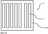
- the device uses the one or more segmented RF electrodes, wherein the segmented RF electrode means RF electrode with e.g. one or more apertures, cutouts and/or protrusions to minimize the effects of a nearby time-varying magnetic field produced by the magnetic field generating device.
- Aperture may be an opening in the body of the RF electrode.
- the cutout may be an opening in the body of the RF electrode along the border of the RF electrode. Openings in the body of the RF electrode may be defined by view from floor projection, which shows a view of the RF electrode from above.
- the apertures, cutouts and/or areas outside of protrusions may be filed by air, dielectric and/or other electrically insulating material.
- the apertures, cutouts and/or protrusions of the RF electrode may minimize induction of eddy currents in the RF electrode, minimize energy loss, and inhibit overheating of the treatment device. Further, the apertures, cutouts and/or protrusions may minimize the influence of the magnetic treatment on the produced RF treatment.
- the proposed design of the RF electrode enables the same applicator to include a magnetic field generating device and a RF electrode with at least partial overlay, according to the applicator's floor projection, while enabling targeting of RF treatment and magnetic treatment to the same area of the patient's body with the parameters described herein. Incorporation of an RF electrode and a magnetic field generating device in one applicator enables enhanced treatment targeting and positive treatment results with minimal negative effects mentioned above.
- the magnetic field generating device in combination with an energy storage device enables production of a magnetic field with an intensity (which may be magnetic flux density) which evokes a muscle contraction.
- Energy storage device may be used to store electrical energy enabling accumulation of an electric field having a voltage in a range from 500 V to 15 kV.
- the energy storage device may supply the magnetic field generating device with the stored electrical energy in an impulse of several microseconds to several milliseconds.
- the method of treatment as described herein enables heating of at least one body area where is also evoked a muscle contraction that minimizes muscle and/or ligament injury, such as tearing or inflammation. Heating of a skin, a contracted muscle, a contracting muscle, a relaxed muscle, adipose tissue, adipose tissue, and/or adjacent biological structure of the treated body area may shift the threshold when a patient may consider treatment to be uncomfortable.
- heating may allow a higher amount of electromagnetic energy, (e.g. RF and/or magnetic field) to be delivered to the patient's body in order to provide more muscle work through muscle contractions and subsequent relaxation.
- electromagnetic energy e.g. RF and/or magnetic field
- Another benefit of application of the RF treatment and the magnetic treatment in the same body area is that the muscle work (provided e.g. by repetitive muscle contractions and relaxation) accelerates blood and lymph flow in the targeted area and so improves dissipation of thermal energy created by the RF treatment.
- Application of the RF treatment and the magnetic treatment also improves homogeneity of biological structure heating that prevents creation of hot spots, edge effects and/or other undesirable effects.
- the method of treatment causing muscle stimulation and heating to the same body area may result in hyperacidity of extracellular matrix that leads to apoptosis or necrosis of the adipose tissue.
- the RF treatment may provide selective heating of adipose tissue that leads to at least one of apoptosis, necrosis, decrease of volume of adipose cells, and cellulite removal.
- the present treatment device and method of use provide new physiotherapy and/or aesthetic treatment by combination of RF treatment and treatment providing muscle stimulation targeted to various treatment effects, such as rejuvenate, heal and/or provide remodeling at least part of at least one biological structure of patient's tissue in at least one body area.
- the biological structure may be any tissue in a human and/or animal body which may have of identical function, structure and/or composition.
- the biological structure may include or be at least part of any type of tissue like: connective tissue (e.g. tendons, ligaments, collagen, elastin fibres), adipose tissue (e.g. adipose cells of subcutaneous adipose tissue and/or visceral adipose tissue), bones, dermis and/or other tissue, such as at least one neuron, neuromuscular plate (neuromuscular junction), muscle cell, one or more individual muscles, muscle group, at least part of a muscle fibre, volume of extracellular matrix, endocrine gland, neural tissue (e.g. peripheral neural tissue, neuron, neuroglia, neuromuscular plate) and/or joint or part of joint.
- the biological structure may be called target biological structure.
- a treatment effect provided to at least part of at least one target biological structure may include muscle contraction (including supramaximal contractions and/or tetanic contractions), muscle twitch, muscle relaxation and heating of biological structure. Also, the treatment effect may include e.g.
- remodelling of the biological structure reducing a number and/or a volume of adipose cells by apoptosis and/or necrosis, muscle strengthening, muscle volume increase, causing of a muscle fibre hypertrophy, muscle fibre hyperplasia, restoration of muscle functionality, myosatellite cells proliferation and/or differentiation into muscle cells, improvement of muscle shape, improving of muscle endurance, muscle definition, muscle relaxation, muscle volume decrease, restructuring of collagen fibre, neocollagenesis, elastogenesis, collagen treatment, improving of blood and lymph flow, accelerate of at least part of at least one target biological structure and/or other functions or benefits.
- more than one treatment effect may be provided and variable treatment effects may be combined.
- the treatment effect provided to target biological structure may results in body shaping, improving contour of the body, body toning, muscle toning, muscle shaping, body shaping, breast lifting, buttock lifting, buttock rounding and/or buttock firming. Further, providing a treatment effect may result in body rejuvenation, such as wrinkle reduction, skin rejuvenation, skin tightening, unification of skin colour, reduction of sagging flesh, lip enhancement, cellulite removing, reduction of stretch marks and/or removing of scars. The treatment effect may also lead to accelerating of healing process, anti-edematic effect and/or other physiotherapeutic and treatment result.
- the treatment device may provide one or more types of treatment energy wherein treatment energy may include magnetic field (also referred as magnetic energy) and RF field (also referred as RF energy) and/or magnetic field (also referred as magnetic energy).
- the magnetic field is provided during magnetic treatment.
- the RF field provided during RF treatment may include electrical component of RF field and magnetic component of RF field.
- the electrical component of RF field may be referred as RF wave or RF waves.
- the RF electrode may generate RF field, RF waves and/or other components of RF field.
- the magnetic field and/or RF field may be characterized by intensity.
- the intensity may include magnetic flux density or amplitude of magnetic flux density.
- the intensity may include energy flux density of the RF field or RF waves.
- a body area may include at least part of patient's body including at least a muscle or a muscle group covered by other soft tissue structure like adipose tissue, skin and/or other.
- the body area may be treated by the treatment device.
- the body area may be body part, such as a buttock, saddlebag, love handle, abdominal area, hip, leg, calf, thigh, arm, torso, shoulder, knee, neck, limb, bra fat, face or chin and/or any other tissue.
- body area may be interchangeable with the term "body region”.
- Skin tissue is composed of three basic elements: epidermis, dermis and hypodermis so called subcutis.
- the outer and also the thinnest layer of skin is the epidermis.
- the dermis consists of collagen, elastic tissue and reticular fibres.
- the hypodermis is the lowest layer of the skin and contains hair follicle roots, lymphatic vessels, collagen tissue, nerves and also fat forming a subcutaneous white adipose tissue (SWAT).
- Adipose tissue may refer to at least one lipid rich cell, e.g. adipose cell like adipocyte. The adipose cells create lobules which are bounded by connective tissue or fibrous septa (retinaculum cutis).
- visceral adipose tissue Another part of adipose tissue, so called visceral adipose tissue, is located in the peritoneal cavity and forms visceral white adipose tissue (VWAT) located between parietal peritoneum and visceral peritoneum, closely below muscle fibres adjoining the hypodermis layer.
- VWAT visceral white adipose tissue
- a muscle may include at least part of a muscle fibre, whole muscle, muscle group, neuromuscular plate, peripheral nerve and/or nerve innervating of at least one muscle.
- Deep muscle may refer to a muscle that is at least partially covered by superficial muscles and/or to a muscle covered by a thick layer of other tissue, such as adipose tissue wherein the thickness of the covering layer may be at least 4, 5, 7, 10 or more centimetres up to 15 cm thick.
- Individual muscles may be abdominal muscles including rectus abdominalis, obliquus abdominalis, transversus abdominis, and/or quadratus lumborum. Individual muscles may be muscle of the buttocks including gluteus maximus, gluteus maxims and/or gluteus minimus.
- Individual muscles may be muscles of lower limb including quadriceps femoris, Sartorius, gracilis, biceps femori, adductor magnus longus/ brevis, tibialis anterior, extensor digitorum longus, extensor hallucis longus, triceps surae, gastroenemiis lateralis/medialis, soleus, .flexor hallucis longus, flexor digitorum longus, extensor digitorum brevis, extensor hallucis brevis, adductor hallucis, abductor halluces, ab/adductor digiti minimi, abductor digiti minimi and/or interossei plantares).
- Ligament may be Cooper's ligament of breast.
- One example may be application of the treatment device and method to patient's abdomen that may provide (or where the treatment may eventually result in) treatment effect such as reducing a number and volume of adipose cells, muscle strengthening, fat removal, restructuring of collagen fibres, accelerate of neocollagenesis and elastogenesis, muscle strengthening, improving of muscle functionality, muscle endurance and muscle shape.
- treatment effects may cause circumferential reduction of the abdominal area, removing of saggy belly and/or firming of abdominal area, cellulite reduction, scar reduction and also improving of the body posture by strengthening of the abdominal muscles that may also improve contour of the body, body look and patient's health.
- One other example may be application of the treatment device and method to body area comprising buttock that may provide (or where the treatment may eventually result in) treatment effect such as reducing a number and volume of adipose cells, restructuring of collagen fibres, accelerate of neocollagenesis and elastogenesis, muscle strengthening, muscle toning and muscle shaping.
- treatment effects may cause waist or buttock circumferential reduction, buttock lifting, buttock rounding, buttock firming and/or cellulite reduction.
- Another example may be application of the treatment device and method to body area comprising thighs that may provide (or where the treatment may eventually result in) reduction of a number and volume of adipose cells, muscle strengthening, muscle shaping and muscle toning.
- the application of the treatment device and method to body area comprising thigh may cause circumferential reduction of the thigh, removing of saggy belly and cellulite reduction.
- Still another example may be application of the treatment device and method to body area comprising arm that may provide (or where the treatment may eventually result in) reduction of a number and volume of adipose cells, muscle strengthening, muscle shaping and muscle toning.
- the application of the treatment device and method to body area comprising arm may cause circumferential reduction of the abdomen, removing of saggy belly and cellulite reduction.
- the one or more treatment effects provided to one or more target biological structures may be based on selective targeting of a RF field into one or more biological structures and providing heating together with application of magnetic field causing muscle stimulation (including muscle contraction).
- the RF treatment may cause selective heating of one or more biological structures, polarizing of extracellular matrix and/or change of cell membrane potential in a patient's body.
- the magnetic field may be time-varying magnetic field or static magnetic field. When the time-varying magnetic field is used, the magnetic treatment may be referred as time-varying magnetic treatment.
- the magnetic treatment may cause muscle contraction, muscle relaxation, cell membrane polarization, eddy currents induction and/or other treatment effects caused by generating time-varying magnetic field in at least part of one or more target biological structures.
- the time-varying magnetic field may induce electric current in biological structure,
- the induced electric current may lead to muscle contraction.
- the muscle contractions may be repetitive.
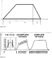
- Muscle contraction provided by magnetic field may include supramaximal contraction, tetanic contraction and/or incomplete tetanic contraction.
- magnetic field may provide muscle twitches.
- the treatment effect provided by using of the treatment device and by application of magnetic treatment and RF treatment may be combined. For example, reduction of a number and volume of adipose cells may be achieved together with muscle strengthening, muscle shaping and/or muscle toning during actual treatment or during a time (e.g. three or six months) after treatment. Furthermore, the effect provided by using of the treatment device by application of magnetic treatment and RF treatment may be cumulative. For example, the muscle toning may be achieved by combined reduction of a number and volume of adipose cells may be achieved together with muscle strengthening.
- the method of treatment may provide the treatment effect to at least one of target biological structure by thermal treatment provided by RF field in combination with applied magnetic treatment.
- the treatment effect to a target biological structure may be provided by heating at least one biological structure and evoking at least a partial muscle contraction or muscle contraction of a muscle by magnetic treatment.
- the method of treatment may enable heating of the body area where the muscle contraction by the magnetic field is evoked.
- the heating may minimize muscle injury and/or ligament injury including tearing or inflammation.
- Heating of a contracting muscle and/or adjacent biological structure may also shift the threshold of uncomfortable treatment. Therefore, heating caused by the RF field may allow a higher amount of magnetic energy to be delivered into patient's biological structure to do more muscle work. Heating of the muscle and/or adjacent biological structure may also improve the quality of and/or level of muscle contraction. Because of heating provided by RF field, more muscle fibres and/or longer part of the muscle fibre may be able to contract during the magnetic treatment. Heating may also improves penetration of muscle stimuli generated by the magnetic treatment. Additionally, when at least partial muscle contraction or muscle contraction is repeatedly evoked, the patient's threshold of uncomfortable heating may also be shifted higher. Such shifting of the threshold may allow more RF energy to be delivered to the patient's body.
- Muscle stimulation in combination with heating may provide better regeneration after treatment and/or better prevention of panniculitis and other tissue injury.
- Repeated muscle contraction followed by muscle relaxation in combination with RF heating may have positive results in treatment and/or suppressing symptoms of diabetes.
- the repetitive muscle contraction induced by provided magnetic field together with heating of the biological structure by RF field may also improve the outcome of diabetes symptoms or positively influence results of diabetes symptoms drug treatment.
- Success of treatment of diabetes symptoms may be caused by penetration of high amount of radiofrequency energy deep to patient's abdomen area. Such penetration may be caused by simultaneous application of magnet treatment that may cause suppressing of patient's uncomfortable feelings related to high amount of RF energy flux density and increased temperature in the tissue.
- magnet treatment may cause polarization and depolarization of patient's tissue that may also increase RF energy penetration to patient's body.
- the RF treatment and/or magnetic treatment may influence glucose metabolism or help with weight loss that may suppress diabetes symptoms. It is a believe that weight loss and exercise of patients with diabetes symptoms may help suppress diabetes symptoms.
- RF treatment by RF field combined with magnetic treatment by magnetic field may also positively influence proliferation and differentiation of myosatellite cells into muscle cells.
- magnet treatment including time periods with different duration, repetition rate and magnetic flux density (e.g. pulses or trains as defined below) may provide a stimulation needed to start proliferation and differentiation of myosatellite cells.
- Method of treatment providing magnetic field including at least two or at least three successive time periods with different duration, repetition rate and magnetic flux density (e.g. pulses, bursts or trains as defined below) may provide a shock to the muscle.
- the regeneration process resulting in proliferation and differentiation of myosatellite cells may be started and further accelerated by delivered RF field. Proliferation and differentiation of myosatellite cells may result in muscle strengthening, restoration of muscle functionality, increasing muscle volume and improvement of muscle shape, body tone or muscle tone.
- the method of application of at least partial muscle stimulation or muscle contraction together with heating to the same body area may result in hyperacidity of the extracellular matrix.
- Hyperacidity may lead to apoptosis of adipose tissue and acceleration of weight loss and body volume loss.
- Hyperacidity may be caused by release of fatty acids into the extracellular matrix, wherein the release of fatty acids may be caused by concentrated high intensity muscle work.
- Concentrated high intensity muscle work may be provided by high number of repetitive muscle contractions causes by application of time-varying magnetic field generated by described magnetic field generating device and treatment device.
- the treatment effect of the RF treatment may be enhanced by magnetic treatment, such as by reducing or eliminating the risk of panniculitis or local skin inflammation since any clustering of the treated adipocytes may be prevented by the improved metabolism.
- the improved blood and/or lymph flow may contribute to removing adipocytes.
- the removal of adipocytes may be promoted by a higher number of cells phagocytosing the adipocytes as well.
- Synergic effects of magnetic treatment and radiofrequency (RF) treatment significantly improves metabolism. Therefore, the possibility of adverse event occurrence is limited and treatment results induced by the present invention are reached in shorter time period.
- the treatment device and the method of a treatment may provide treatment of the same patient's body area, wherein the magnetic treatment and the RF treatment may be targeted into at least part of one or more biological structures.
- One or more volumes of patient's body tissue affected by targeted RF and/or magnetic treatment may be in proximity.
- the volume of at least part of at least one or more affected biological structures of patient's body tissue may be defined as an affected tissue volume wherein the treatment effect provided by treatment device and/or method of treatment described above takes place.
- the treatment effect may be caused by repeated muscle contraction (provided e.g. magnetic treatment) changing of a tissue temperature (provided e.g. RF treatment), and/or by at least partial polarization and acceleration of molecules in the patient's tissue (preferably provided by RF treatment and magnetic treatment).
- Changing of a tissue temperature may include e.g. an increasing tissue temperature of at least 3 °C or 4 °C or 5 °C or 6 °C or 7 °C or 10 °C with reference to normal tissue temperature. Further, changing of a tissue temperature may include an increase or decrease of tissue temperature in the range of 1 °C to 50 °C to 2 °C to to 30 °C or 2 °C to 25 °C as compared to the untreated tissue located in the same or different body area. Changed tissue temperature may be interpreted as change of temperature in any volume or any area of the biological tissue.
- Proximity of affected tissue volumes by at least one RF treatment and/or by at least one magnetic treatment has meaning of a distance between two affected tissue volumes.
- At least two proximate affected tissue volumes may have at least partial overlay wherein 2 % to 15 % or 5 % to 30 % or 2 % to 100 % or 30 % to 60 % or 80 % to 100 % or 40 % to 85 % of smaller affected tissue volume may be overlaid by larger affected tissue volume.
- the distance between volumes of affected tissue may be in a range of 0.01 cm to 10 cm or in the range of 0.01 cm to 5 cm, 0.01 cm to 3 cm, or 0.01 cm to 1 cm.
- the overlay in the ranges mentioned above may apply for two or more affected tissue volumes having an identical volume without any differentiation between smaller or larger tissue volumes.
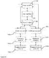
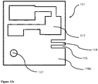
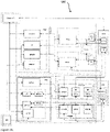
- FIGs 1a - 1e show exemplary schematic diagrams of the treatment device. The diagrams may apply only to main unit and applicator.
- the treatment device may include input interface 103, control system 104, power source 105, power network 106, one or more treatment clusters 107 and one or more treatment energy sources 108.
- Plurality of treatment energy sources 108 may be coupled to or communicate with at least one treatment cluster 107.
- Control system 104 may be coupled to and communicate with each treatment cluster.
- Shown parts of treatment device in Figures 1a - 1e may be electrical elements of circuitry. Also, one or more shown parts of diagrams in Figures 1a-1e may include plurality of individual electrical elements. Electrical elements may generate, transfer, modify, receive or transmit electromagnetic signal (e.g. electrical) signal between individual electrical elements.
- the electromagnetic signal may be characterized by current, voltage, phase, frequency, envelope, value of the current, amplitude of the signal and/or their combination.
- the electromagnetic signal reaches the treatment energy source, the respective treatment energy source may generate treatment energy and/or field.
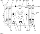
- Input interface 103 may receive input from a user.
- Input interface may include human machine interface (HMI).
- HMI may include one or more displays, such as a liquid crystal display (LCD), a light emitting diode (LED) display, an organic LED (OLED) display, which may also include a touch-screen display.
- HMI may include one or more controlling elements for adjustment or controlling treatment device. Controlling element may be at least one button, lever, dial, switch, knob, slide control, pointer, touchpad and/or keyboard.
- the input interface may communicate or be coupled to control system or power network.
- the user may be an operator (e.g. medical doctor, technician, nurse) or patient himself, however the treatment device may be operated by patient only. In most cases, the treatment device may be operated by the user having an appropriate training.
- the user may be any person influencing treatment parameters before or during the treatment in most cases with exception of the patient.
- Control system 104 may include a master unit or one or more control units. Control system may be an integral part of the input interface 103. Control system 104 may be controlled through the input interface 103. Control system may include one or more controlling elements for adjustment or controlling any part or electrical elements of treatment device. Master unit is a part of treatment device (e.g. applicator and/or main unit) or electrical element of circuitry that may be selected by the user and/or treatment device in order to provide master-slave communication including high priority instructions to other parts of the treatment device. For example, master unit may be a control unit or part of input interface providing high priority instructions to other parts of the treatment device. The treatment device may include a chain of master-slave communications.
- Treatment device may include a chain of master-slave communications.
- treatment cluster 107 may include one control unit providing instructions for electrical elements of the treatment cluster 107, while the control unit of treatment cluster 107 is slave to master unit.
- Control system 104 may be coupled or communicate with input interface 103, one or all power source 105, power network 106, and/or with one or all treatment clusters present in the treatment device.
- the control system 104 may include one or more processors (e.g. a microprocessors) or process control blocks (PCBs).
- processors e.g. a microprocessors
- PCBs process control blocks
- the power source 105 may provide electrical energy including electrical signal to one or more treatment clusters.
- the power source may include module converting AC voltage to DC voltage.
- the power network 106 may represent a plug.
- the power network may represent a connection to power grid.
- the power network may represent a battery for operation of the treatment device without need of a power grid.
- the power network may provide electrical energy needed to operation to whole treatment device and/or its parts. As shown on exemplary diagrams in Figures 1a - 1e , the power network provides electrical energy to input interface 103, control system 104 and power source 105.
- the treatment cluster 107 may include one or more electrical elements related to generation of respective treatment energy.
- the treatment cluster for magnetic treatment (referred as HIFEM) may include e.g. an energy storage element and switching device.
- the treatment cluster for RF treatment (referred as RF cluster) may include e.g. power amplifier and/or filter.
- the treatment energy source 108 may include a specific source of treatment energy.
- the treatment energy source of magnetic field may be a magnetic field generating device e.g. a magnetic coil.
- the treatment energy source of RF energy (including RF waves) may be RF electrode.
- the treatment device may include one or more treatment circuits.
- One treatment circuit may include a power source, electrical elements of one treatment cluster and one respective treatment energy source.
- the magnetic circuit may include a power source, HIFEM cluster and magnetic field generating device.
- the RF circuit may include a power source, RF cluster and magnetic field generating device.
- the electromagnetic signal generated and/or transmitted within a treatment circuit for RF treatment may be referred as RF signal.
- the wiring connecting respective electrical elements of the one treatment cluster may also be included in the respective cluster.
- Each of the treatment clusters in Figures 1a-1e described in the detail below may be any of HIFEM, RF or combination.
- the one or more treatment circuits and/or their parts may be independently controlled or regulated by any part of control system 104.
- the speed of operation of HIFEM cluster of one treatment circuit may be regulated independently on the operation of HIFEM cluster of another treatment circuit.
- the amount of energy flux density of delivered by operation of RF electrode of one treatment circuit may be set independently from the operation of RF electrode of another treatment circuit.
- Figure 1a shows an exemplary diagram of the treatment device including input interface 103, control system 104, power source 105, power network 106, two treatment clusters including treatment cluster A 107a, treatment cluster B 107b, treatment energy source A 108a and treatment energy source B 108b.
- treatment device may include two treatment circuits.
- One treatment circuit may include a power source 105, treatment cluster A 107a and/or treatment energy source A 108a.
- Another treatment circuit may include a power source 105, treatment cluster B 107b and/or treatment energy source B 108b.
- Treatment clusters 107a and 107b may communicate with each other.
- Figure 1b shows an exemplary diagram of the treatment device including input interface 103, control system 104, two power sources including a power source A 105a and a power source B 105b, power network 106, two treatment clusters including treatment cluster A 107a and treatment cluster B 107b, treatment energy source A 108a and treatment energy source B 108b.
- treatment device may include two treatment circuits.
- One treatment circuit may include a power source 105a, treatment cluster A 107a and/or treatment energy source A 108a.
- Another treatment circuit may include a power source B 105b, treatment cluster B 107b and/or treatment energy source B 108b.
- Treatment clusters 107a and 107b may communicate with each other.
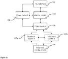
- Figure 1c shows an exemplary diagram of the treatment device including input interface 103, control system 104, power source 105, power network 106, two treatment clusters including treatment cluster A 107a and treatment cluster B 107b and one treatment energy source 108.
- treatment device may include two treatment circuits.
- One treatment circuit may include a power source 105, treatment cluster A 107a and/or treatment energy source 108.
- Another treatment circuit may include the power source 105, treatment cluster B 107b and/or treatment energy source 108.
- Treatment clusters 107a and 107b may communicate with each other.
- the shown diagram may include a magnetic field generating device providing both RF treatment and magnetic treatment.
- Figure 1d shows an exemplary diagram of the treatment device including input interface 103, control system 104, power source 105, power network 106, four treatment clusters including treatment cluster A1 107a, treatment cluster A2 107aa, treatment cluster B1 107b, treatment cluster B2 107bb and four treatment energy sources including treatment energy source A1 108a, treatment energy source A2 108aa, treatment energy source B1 108b and treatment energy source B2 108bb.
- treatment device may include four treatment circuits.
- First treatment circuit may include a power source 105, treatment cluster A1 107a and/or treatment energy source 108a.
- Second treatment circuit may include the power source 105, treatment cluster A2 107aa and/or treatment energy source A2 108aa.
- Third treatment circuit may include a power source 105, treatment cluster B1 107b and/or treatment energy source B1 108b.
- Fourth treatment circuit may include a power source 105, treatment cluster B2 107bb and/or treatment energy source B2 108bb.
- the treatment energy sources of the first treatment circuit and second treatment circuit may be positioned in one applicator, while the treatment energy sources of the third treatment circuit and fourth treatment circuit may be positioned in another applicator.
- Figure 1e shows an exemplary diagram of the treatment device including input interface 103, control system 104, two power sources including power source A 105a and power source B 105b, power network 106, four treatment clusters including treatment cluster A1 107a, treatment cluster A2 107aa, treatment cluster B1 107b, treatment cluster B2 107bb and four treatment energy sources including treatment energy source A1 108a, treatment energy source A2 108aa, treatment energy source B1 108b and treatment energy source B2 108bb.
- treatment device may include four treatment circuits.
- First treatment circuit may include a power source A 105a, treatment cluster A1 107a and/or treatment energy source 108a.
- Second treatment circuit may include a power source A 105a, treatment cluster A2 107aa and/or treatment energy source A2 108aa.
- Third treatment circuit may include a power source B 105b, treatment cluster B1 107b and/or treatment energy source B1 108b.
- Fourth treatment circuit may include a power source B 105b, treatment cluster B2 107bb and/or treatment energy source B2 108bb.
- the treatment energy sources of the first treatment circuit and second treatment circuit may be positioned in one applicator, while the treatment energy sources of the third treatment circuit and fourth treatment circuit may be positioned in another applicator.
- the additional treatment device may be on the same level of independency as the whole treatment device.
- the treatment device may include a remote control 13.
- Remote control 13 may include a discomfort button for safety purposes so that when a patient feels any discomfort during the treatment, the user may press the discomfort button.
- the discomfort button When the discomfort button is pressed, remote control 13 may send a signal to a main unit and stop treatment. Also, the remote control 13 may inform the user through a human machine interface (HMI).
- HMI human machine interface
- the operation of the discomfort button may override the instructions from master unit.
- the discomfort button may be coupled to or be part of the main unit 11.
- the main unit 11 may be coupled or connected to one or more additional treatment devices 14 that may be powered by the main unit 11. However, the treatment device including main unit 11 may be paired by software with the one or more additional treatment devices 14. Also, one or more additional treatment devices 14 may be also powered by their own source or sources of energy.
- the communication device 15, additional treatment device 14, remote control 13 and at least one applicator 12 may each communicate with the main unit 11. Communication may include sending and/or receiving information. Communication may be provided by wire and/or wirelessly, such as by internet network, local network, RF waves, acoustic waves, optical waves, 3G, 4G, 5G, GSM, HUB switch, LTE network, GSM network, Bluetooth and/or other communication methods or protocols.
- the additional treatment device 14 may be any device that is able to provide at least one type of treatment energy (e.g.: RF field, magnetic field, ultrasound, light, time-varied mechanical pressure, shock wave, or electric current) to a patient's body to cause treatment effect to at least one target biological structure.
- the additional treatment device 14 may include at least one electrical element generating treatment energy for at least one treatment e.g. magnet, radiofrequency, light, ultrasound, heating, cooling, massage, plasma and/or electrotherapy.
- the additional treatment device 14 may be able to provide at least one treatment without instructions from the main unit 11.
- the additional treatment device 14 may communicate with the main unit 11, communication device 15 and/or other additional treatment devices 14.
- the additional treatment devices 14 may be any other device of the same or other company wherein the device may be able to provide specific one or more type of treatment energy.
- the additional treatment device 14 may be an extension of the treatment device , wherein the additional treatment device 14 may provide treatment energy with parameters defined by the HMI of the main unit 11.
- the communication device 15 may be connected by wire and/or wirelessly to the main unit 11.
- the communication device 15 may be a computer, such as a laptop or desktop computer, or a mobile electronic device, such as a smartphone, or an electronic tablet.
- the communication device may send and/or receive information linked with a treatment, functionality of the treatment device, and/or other information.
- the additional treatment device 14 and/or the communication device 15 may communicate directly with the main unit 11 or indirectly with the main unit 11 through one or more additional or communication devices.
- the communication device may include receiver, transmitter and a control unit to process sent and/or received information.
- Sent and/or received information from or to an individual part of the treatment device may include data from communication between communication device 15 and the main unit 11, data from communication between applicator 12 and the main unit 11, data from communication between additional treatment device 14 and the main unit 11 and/or data from communication between the remote control 13 and the main unit 11.
- Sent and/or received information may be stored in a black box, cloud storage space and/or other storage devices.
- the black box may be part of the main unit 11 or any other part of the treatment device.
- Other storage device may be USB, other memory device and/or also communication device with internal memory.
- At least part of sent and/or received information may be also displayed by HMI. Sent and/or received information may be displayed, evaluated and/or changed by the user through the HMI and/or automatically by control system.
- One type of the sent and/or received information may be predetermined or current value or selection of one or more treatment parameters or patient information.
- Patient information may include e.g. gender of a patient, age and/or body type of the patient.
- Sent and/or received information may also inform external authorities, like a support centre, e.g. a service and/or a sale department, that are also subset of communication devices.
- Sent and/or received information to external authorities may include information about the condition of the treatment device, history of one or more provided treatments, operational history of the treatment device, software update information, wear out information, durability of the RF electrode, durability of the magnetic field generating device, treatment warnings, treatment credit/billing information, such as information of number of paid treatments or credits, and/or other operation and usage information.
- One possible type of sent and/or received information may be recognition of connection of one or more applicators 12, the remote control 13, additional treatment devices 14, and/or communication devices 15, According to information the treatment device may manually or automatically recognize type of connected additional treatment device 14 and/or applicator 12. Automatic recognition may be provided by control system. Based on information about connection of one or more applicators 12, connection of additional treatment devices 14 and/or communication devices 15, the treatment device may provide actualization of HMI, show notification about the connection to applicators and/or possible optimization of new treatment options. Possible optimization of new treatment options may include e.g. adjusting of at least one treatment parameter, implementing additional treatment energy source, change of parameters of new treatment energy source and/or other.
- the treatment device e.g.
- control system may automatically adjust or offer adjustment treatment parameters based on newly connected applicator 12 and/or additional treatment devices 14.
- Recognition of connected applicator 12, additional treatment device 14 and/or communication device 15 may be based on by specific connectors (e.g., a specific pin connector). Also, the recognition of connection may be provided by a specific physical characteristic like an impedance of connected part or by a specific signal provided by the applicator or its connected part to the main unit 11. Connection between individual parts of the treatment device such as the main unit 11, the applicator 12, the remote control 13, the additional treatment device 14 and/or the communication device 15 may be provided by wire and/or wirelessly (e.g. by RFID tag, RF, Bluetooth, and/or light electromagnetic pulses).
- the applicator 12 may by connected to the main unit 11 by a wire to be powered sufficiently.
- the application may be connected through a wireless connection in order to communicate with the main unit 11 and/or with communication device 15.
- additional treatment device 14 and/or communication device 15 may be recognized by software recognition, specific binary ID, manual recognition of the parts selected from the list implemented in the treatment device, and/or by a pairing application.
- the connector side in the main unit 11 may include a unit able to read and/or recognize information included in the connector side of the applicator and/or connector side of the additional treatment device. Based on read and/or recognized information, the applicator and/or the additional treatment device may be recognized by main unit 11.
- the connector side of the main unit 11 may serve as a first side connector of the connection, wherein the connection of the applicator or additional treatment device may serve as a second side connector of the connection.
- Sending of the information, receiving of the information and/or recognition of the second side connector by the first side connector may be based on binary information received by conductive contact between these two connector sides, by optical reading and/or by recognition provided by the first side connector.
- Optical recognition may be based on, for example, reading of specific QR codes, barcodes and the like for the specific applicators 12.
- the first side connector located in the main unit 11 may include a unit able to read/recognize binary information implemented in the second side connector of a cable from the applicator 12 and/or additional treatment device 14.
- Implemented information in the second side connector may be stored in an SD card. Based on such implemented information any part of the treatment device may be recognized by the main unit 11.
- Communication between individual parts of the treatment device may be based on peer-to-peer (referred as P2P) and/or master-slave communication.
- P2P peer-to-peer
- the individual parts of the treatment device have the same priority of its commands and/or may communicate directly between each other.
- P2P communication may be used during initial recognition of connected individual parts of the treatment device.
- P2P communication may be used between some parts of the treatment device during a treatment, such as between communication devices.
- Master-slave communication may be used between individual parts of the treatment device for at least a short time during, before and/or after each treatment of individual patient.
- one part of the treatment device may provide commands with the highest priority.
- the individual part of the treatment device e.g. as the main unit 11 may provide commands with the highest priority and is referred as master unit.
- the treatment device may include at least one master-slave communication between an individual electrical element, such as a power source and or one or more control units, where the one or more control units act as master.
- the master unit may be selected by a user before, after and/or during the treatment.
- the user may select master unit from available individual parts or electrical elements of the treatment device. Therefore, the user may select the main unit 11, the applicator 12, the remote control 13, the additional treatment device 14 or the communication device 15 as the master unit.
- the master unit may be a control unit in selected present in individual part of the treatment device e.g. a control unit in the main unit 11.
- the user may select the master unit in order to facilitate adjusting of treatment parameters.
- the user may also select the communication device 15 as a master unit, wherein the communication device selected as master device may provide control of more than one treatment device.
- the main unit 11 may include a control unit as a master unit that monitor and evaluate at least one parameter of the treatment, such as patient's temperature, voltage on individual elements of the treatment device and/or other, that enable to provide safe treatment even if the connection between.
- the master unit may be independent electrical element outside of human machine interface. The master unit may be controlled by user through human machine interface.
- the master unit may be selected automatically based on a predetermined priority value of the connected parts of the treatment device. Selected master unit may remain unchanged and already selected part of the treatment device may act as the master unit during the whole treatment. However, the selection of master unit may be changed during the treatment based on command priority and/or choice of the user.
- the master unit may be also determined according to manufacturing configuration or being dependent on factory reset. For example, the remote control 13 may provide command with the highest priority to stop the treatment when patient feels discomfort and the treatment will be stopped without relevance of which individual part of the treatment device was set as the master unit and set parameters of the treatment.
- Figures 2-5 illustrate several possible master-slave communication schemes that may be used in communication between the main unit 11 and one or more applicators 12, remote controls 13, additional treatment devices 14, and/or communication devices 15.
- one or more therapy generators 201 generate a modified electrical signal in order to provide a signal to a treatment energy source, such as the RF electrode and/or the magnetic field generating device.
- the therapy generators 201 may include a group of electrical elements or at least two members of the group of electrical elements present in the circuitry of the treatment device and/or main unit.
- the group of electrical elements may include a control unit, power source, system of coaxial cables, one or more switches, one or more energy storage devices, one or more pin diodes, one or more LC circuits, one or more LRC circuits, one or more power amplifiers and/or other part of the treatment device actively modifying electrical signal in controlled manner.
- the therapy generator may provide modifying of electrical signal in controlled manner.
- Modifying electrical signal in controlled manner may include e.g. providing and/or controlling impedance adjustment of provided RF treatment based on impedance matching measured across patient's tissue and/or RF electrodes.
- Actively modified electrical signal may be interpreted such that electrical signal may have different parameters, such as frequency, symmetrisation, amplitude, voltage, phase, intensity, etc.
- the parameters of electrical signal may be based on requirements of treatment including the type of the patient, treatment parameters.
- the parameters of electrical signal may be modified on feedback information, such as measured standing wave ratio of RF energy, temperature of tissue, temperature of RF electrode, temperature of the inside of the applicator, temperature of the surface of the applicator, electric current and voltage of individual elements of the treatment device and/or other.
- the diagram of Figure 2 shows a security 203 that prevent any unauthorized intrusion to the treatment device communication and protects personal user data and/or account.
- the security 203 may protect the treatment device from computer viruses, unauthorized access and/or protect the communication between individual parts of the treatment device from reading or change by unauthorized medium or person.
- the security 203 may provide coding of the information used in communication and/or antivirus services preventing intrusion of unwanted binary code into the treatment device and/or communication.
- the security 203 may correct mistakes created during the communication.
- the security 203 may block connection of unauthorized/unwanted external device to the treatment device.
- the security 203 in Figure 2 may be located in the communication diagram between the master unit 202 and a communication interface 204.
- the security 203 may also be part of an element user 208, a service 207, and/or a sale 206.
- the security 203 may be located also between the communication interface 204 and a communication medium 205, the therapy generator 201, and/or may be part of them.
- the communication interface 204 may include hardware and/or software components that enables to translate electric, electromagnetic, infrared and/or other signal into readable form to enable communication between at least two parts of the treatment device and/or other communicating sides or medium.
- the communication interface 204 may provide communication and/or coding of the information and/or data.
- the communication interface 204 may be, for example, a modem or GSM module providing communication between the treatment device and online network or server.
- the communication interface 204 may be part of the master unit 202, the therapy generator 201, and/or other part of the treatment device.
- the communication medium 205 may be medium transferring communication data.
- the communication medium 205 may be used in communication between the treatment device and the user 208, the service 207 and/or the sale 206.
- the communication medium 205 may be a wire, SD card, flash memory, coaxial wire, any conductive connection, server, some kind of network on principle, such as RF waves, acoustic waves, optic waves, GSM, 3G, 4G, 5G, HUB switch, Bluetooth, Wi-Fi and/or other medium which may include one or more servers.
- Communication data/information may be redirected to the individual parts of the treatment device and/or to individual users or services, such as the user 208, the service 207 and/or the sale 206.
- Communication data/information may be redirected by the master unit 202, the communication medium 205 and/or the therapy generator 201.
- server may filter data for the user 208 and filter other communication information that will be redirecting to the service 207 control unit and/or other part of the treatment device.
- the element called "user 208" of Figure 2 may be a representation of the HMI controlled by a user.
- the element called “user 208” of Figure 2 may a representation of the other communication device (personal computer, laptop, mobile, tablet, etc.) controlled by user, wherein the communication device may send information to at least one part of the treatment device and/or receive information from at least one part of the treatment device.
- Information provided by this communication channel may be a type of a treatment protocol, information about treatment effect, actual value and/or predetermined value of one or more treatment parameters, feedback information, selection of treated body area, recommendations of behaviour before and after the treatment and/or other information. At least part of the information may be sent to the user controlling the treatment device and also to the patient, such as by an software application for mobile phone, tablet or laptop.
- the service 207 in Figure 2 may represent a service department that has authorized access to information about the treatment device.
- the service 207 may be the service department of the company providing or manufacturing the treatment device wherein the communication between the service department of the company and the user may be provided through the HMI, a communication device and/or automatically through preprogrammed software interface.
- Information provided by this communication channel may include wear of individual electrical element of the treatment device, durability of any RF electrode and/or magnetic field generating device, malfunction of an individual electrical element, possible software optimization and/or actualization of the device, providing applications for connection of another additional treatment device and/or other. Optimization and/or actualization of the treatment device may include e.g. a remote access to the treatment device software and/or fixing errors.
- the sale 206 in Figure 2 may be a sales department with authorized access to information about the treatment device.
- the sale 206 may inform the user about a type of accessories which may be added to the treatment device. Further the sale 206 may mediate sales of the plug-in modules and/or mediate sales of accessories of the treatment device. Furthermore, the sale 206 may provide an offer linked with billing and renting system.
- Information exchanged by communication to or from sale 206 may be, for example, the number of treatments, time of treatments, and/or type of applied treatment, information about applicators and/or others.
- the treatment device may include a black box for storing a data regarding the treatment history, operational history, communication between individual parts of the treatment device, data from or for a billing and renting system, operational errors, and/or other information.
- the data may be accessible to the sale 206, to the service 207 and/or to the user 208 via the communication medium (e.g., a storage cloud and/or server).
- the treatment device may include a billing and renting system to manage charges for using of the treatment device and/or respective additional treatment devices.
- the billing and renting system may send such information to a provider in order to prepare the billing invoice.
- Data from the black box may be downloaded by verified authorized personnel, such as a service technician, accountant and/or other person with administrator access. Verification of the authorized person may be provided by specific key, password, software code of several bits and/or by specific interconnecting cable.
- the billing and renting system may be based on credits subtracted from a user account. Credits may be predefined by the provider of the treatment device, e.g. a producer of the treatment device. Credits may be recharged during the time when the treatment device is in operation and/or may be recharged to online account linked with one or more treatment devices of the user and/or provider. Credits may be subtracted according to the selected treatment protocol or body area. Credit value for individual one or more treatments and/or part of the treatment may be displayed to the user before treatment starts, during the treatment and/or after the treatment. If the credit in the user's account runs out, the treatment device may not enable any further treatment until credits are recharged.
- Credits may be used as a currency changed for individual treatment wherein different treatment may cost a different amount of credits based on the type of the treatment, the duration of the treatment, the number of used applicators, and/or other factors. Credits may be also used for renting or buying individual part of the treatment device, whole treatment device, hardware or software extensions of the treatment device and/or other consumables and spare parts belonging to the treatment device. Interface where the credit system may be recharged may be part of the treatment device, HMI and/or online accessible through website interface.
- One or more software extension may be linked with the treatment device and method of treatment.
- One or more software extensions may be downloaded to any communication device, such as a smartphone, tablet, computer and/or other electronic device.
- the software extension may communicate with the main unit and/or other part of the treatment device.
- the communication device with installed software extension may be used for displaying or adjusting of one or more treatment parameters or information associated to the treatment.
- Such displayable treatment parameters and information associated to the treatment may include e.g. time progress of the treatment, measured size of treated body area before and/or after individual treatments, schematic illustrations of applied bursts or trains, remaining time of the treatment, heart rate of the patient, temperature of patient's body e.g.
- the software extension may be also provided to the patient in order to inform them about the schedule of treatments, mapping progress between individual treatments, percentile of treatment results compared to other people and/or recommendations of behaviour before and/or after the treatment.
- Recommendations of behaviour may include e.g. recommendation what volume of water should patient drink during the day, how should patient's diet look like, what type and volume of exercise should patient provide before and/or after treatment and/or other information that may improve results of treatment.
- Communication between individual elements of the communication diagram may be bidirectional or multidirectional.
- connection between the user 208, the service 207, the sale 206, communication medium 205 and/or connection between the therapy generator 201 and the master unit 202 may be secured by the security 203 to provide safe communication and eliminate errors.
- the security 203 may be located between the master unit 202 and the communication interface 204 and/or between the communication medium 205 and the communication interface 204.
- a server 301 may include the security 203.
- the security 203 may be implemented in individual access of the user 208, the service 207, and/or the sale 206.
- the communication medium 205 may communicate with one or more therapy generators 201.
- One or more therapy generator 201 may communicate with the master unit 202.
- the information from the communication medium 205 may be verified by the security 203 before the therapy generator 201 sends information to the master unit 202.
- Figure 5 shows a schematic diagram of communication between the communication medium 205 and one or more therapy generators 201A-201D.
- the therapy generator A 201A may communicate with at least one or more therapy generator 201B-201D.
- Another therapy generator B 201B may also communicate with one or more therapy generators 201A, 201C, 201D.
- Therapy generator C 201C may not directly communicate with the therapy generator A 201A and may communicate through therapy generator B 201B.
- the security 203 may be in the communication pathway between each therapy generator 201A-201D and/or between the therapy generator 201A and the communication medium 205.
- FIG. 6 show the main unit 11 of the treatment device.
- the main unit 11 may include a HMI 61, a ventilator grid 62, at least one applicator holders 63a and 63b, at least one device control 64, applicator connectors 65a and 65b, at least one main power supply input 66, a curved cover 67 of the main unit 11, wheels 68, a main unit cover opening 69, a main unit handle 70, and/or a logo area 71.
- the main power supply input 66 may provide coupling or connection to the power grid or power network.
- the ventilator grid 62 of the treatment device may be designed as one piece and/or may be divided into multiple ventilator grids 62 to provide heat dissipation.
- the ventilator grid 62 may be facing toward a person operating the main unit 11, facing the floor and not being visible and/or ventilator grid 62 may be on the sides of the main unit 11.
- the floor-facing location of the ventilator grid may be used to minimize disturbing noise for the patient, because processes like cooling of the main unit 11 and/or electrical elements powered by electric energy may produce noise.
- Surface area of all ventilator grids 62 on the surface of the main unit 11 may be in a range from 100 cm 2 to 15000 cm 2 , or from 200 cm 2 to 1000 cm 2 , or from 300 cm 2 to 800 cm 2 .
- Manipulation with the main unit 11 may be provided by rotating wheels 68 on the bottom of the main unit 11 and/or by the main unit handle 70.
- the logo area 71 of the company providing the treatment device may be located below the main unit handle 70 and/or anywhere on the curved cover 67 and HMI 61.
- the front side of the main unit 11 facing the patient may be designed as a curved cover 67 of the main unit.
- the front side of the main unit 11 facing the patient may have no right angles according to floor projection of the main unit 11.
- the front side of the main unit 11 facing the patient may be designed as one, two or more pieces covering the inside of the main unit 11.
- the main unit 11 with curved facing side may improve manipulation of the main unit 11 itself nearby patient's support wherein the risk of collision main unit 11 and various sensitive body parts of the patient (e.g. fingers) is minimized.
- Facing side of the main unit 11 may also include the main unit cover opening 69.
- the main unit cover opening 69 may include a thermal camera for monitoring the temperature of the patient or treated body area, a camera for monitoring the location of one or more applicators, movement of the patient and/or other.
- the main unit cover opening 69 may be represented by opening in the curved cover 67 of the main unit.
- the main unit cover opening 69 may include one or more connectors for connecting additional treatment devices.
- the main unit cover opening 69 may include one or more sensors, such as camera, infrared sensor to scan patient's movement, heating of treated body area and/or biological structure. Based on information from such sensors, actual value and/or predetermined value of one or more treatment parameters may be optimized when patient moves, skin surface reach temperature threshold limit, determine treated body area and/or other.
- the front side of the main unit 11 may also include one or more applicator connectors 65a and/or 65b.
- Applicator connectors 65a and 65b facing the patient may be closer to patient's body than applicators connected to side facing the operator (e.g. doctor or technician). Accordingly the length of the connecting tube 814 connecting the applicator with the main unit 11 may be minimized. Manipulation with the applicator and/or plurality of the applicators connected by shorter connecting tubes 814 may be easier than with the applicator connected with the longer connecting tube 814..
- the front side of the main unit 11 may have no corners and/or angles and may include at least partially elliptical and/or circular curvature.
- the curvature may have a radius of curvature in a range of 20 cm to 150 cm, 30 cm to 100 cm, 30 cm to 70 cm, or 40 to 60 cm,
- An angle of the main unit 11 front side curvature may be in a range of 30 ° to 200 °, or of 50 ° to 180 °, or of 90 ° to 180 °.
- the angle of the curvature may be defined with the same principle as it is defined an angle 30 of a section 26 in Figure 23 as discussed in further detail below.
- the main unit 11 may include one or more an applicator holder e.g. 63a and 63b. Alternatively, one or more applicator holders may be coupled to the main unit 11. Each applicator holder 63a and 63b may have specific design for different types of the applicator. The applicator holder 63a and 63b may each hold a single applicator 12a or 12b. Each applicator holder 63a, 63b may have several functions. For example, the applicator holders 63a and 63b may be used for pre-heating or pre-cooling of at least part of the applicator.
- the applicator holders 63a and 63b may include another HMI and be used for displaying information about selected treatment, actual value and/or predetermined value of one or more treatment parameters. Also, the applicator holder 63a and/or 63b may provide indication whether an applicator is ready to use. Furthermore, the applicator holder 63a and/or 63b may indicate a current value temperature of at least part of the applicator. The indication may be provided by color flashing or vibration. The applicator holder 63a and/or 63b may be used to set actual value and/or predetermined value of one or more treatment parameters and/or applicator parameters, such as a temperature of applicator's part contacting the patient.
- the main unit 11 may include device control 64 for switching on and off the main unit 11, manual setting of power input parameters and/or other functions.
- the applicator connectors 65a and 65b may be used for transfer of electrical and/or electromagnetic signal from the main unit 11 and applicators.
- the applicator connectors 65a and 65b may be used for connecting of one or more applicators (via the connecting tube 814), the communication device, the additional treatment device and/or memory storage devices such as USB, SSD disc, diagnostic devices, and/or other memory storage devices known in the state of art.
- the applicator connectors 65 e.g. 65a and/or 65b for connecting of one, two or more applicators may be located in the main unit 11 or on the side of the main unit 11.
- the length of coaxial cables may be linked with a frequency of transmitted electrical signal.
- the length of connection from the main unit 11 to e.g. applicator 12a (and therefore connecting tube 814) should be as long as possible.
- length of at least one coaxial cable between electrical elements in the main unit 11 may be linked with a frequency of transmitted electrical signal (e.g. RF signal) sent to at least treatment energy source (e.g. RF electrode to provide RF energy). Therefore the length of at least one coaxial cable inside the main unit (e.g. between a power source and the applicator connector 65a and/or 65b) may be as short as possible.
- the length of coaxial cable located in the main unit 11 may be in a range of 3 cm to 40 cm, or 7 cm to 30 cm, or 10 cm to 20 cm.
- the applicator connectors 65a and 65b may be located on the curved front side of the main unit 11.
- the HMI 61 may include a touch screen display showing actual value and/or predetermined value of one or more treatment parameters.
- the touch screen may provide option to choose the displayed treatment parameters and/or adjust them.
- the HMI 61 may be divided into two display sections 61a and selection section 61b.
- the display section 61a may display actual value and/or predetermined value of one or more treatment parameters and other information for the user.
- the selection section 61b of the HMI 61 may be used for selection of treatment parameters and/or other adjustment of the treatment.
- HMI may be included in, coupled to or be part of one or more applicators 12, main unit 11, an additional treatment device 14 and/or in other one or more communication devices 15.
- the HMI may be included in the main unit 11.
- the HMI may be fixed in a horizontal orientation on the main unit 11 or the HMI 61 may be oriented or tilted between 0 ° to 90 ° degrees with respect to a floor or other horizontal support surface.
- the angle between the HMI 61 plane and a floor may be adjusted by at least one joint or may be rotated around at least one Cartesian coordinates.
- the HMI 61 may be in form of detachable HMI, e.g. a tablet.
- the HMI 61 may be telescopically and/or rotationally adjusted according to one two or three Cartesian coordinates by a holder that may adjust distance of HMI 61 from the main unit 11 and/or orientation of the HMI 61 with regard to the main unit 11 and the user.
- the holder may include at least one, two or three implemented joint members.
- One HMI 61 may be used for more than one type of the treatment device provided by the provider.
- the HMI software interface may be part of the main unit software or part of the software included in one or more additional treatment devices and/or communication devices.
- the software interface may be downloaded and/or actualized by connection with the communication device, the additional treatment device, flash memory device, the remote connection with sales, the service and/or the internet.
- Figure 26 shows exemplary layout of the interior of the main unit 11.
- the interior of the main unit 11 may include multiple electrical elements control system, one or more control units of RF circuits, magnet circuits and/or other elements needed for correct function of the treatment device. Location of individual elements in the main unit 11 may be described by Cartesian coordinates with the zero values at the bottom edge of the front side facing the patient.
- the main unit 11 may include one or more struts 74. At least two struts 74 may create an X-shape that may be fixed at its ends to other vertical struts 74 to create construction for the main unit 11.
- the main unit 11 may include at least one cooling system 78 configured to cool electrical element such as one or more control units, PCBs, power sources, switches, energy storage devices and/or other electrical element of the treatment device.
- the cooling system 78 may be used for providing and/or cooling the cooling fluid provided to the applicator.
- the SYM element 79 may be located in the upper third of Z coordinate and at the first third of the X coordinate nonmatter of Y coordinate. Function of the SYM is explained below.
- the main unit 11 may also include one or more cases 72 formed from aluminium or other metal materials.
- the one or more cases 72 may provide electrical, electromagnetic and/or radiation insulation (later only as insulation) of one or more internal parts of the main unit 11 from other part of the main unit 11.
- At least part of a RF circuit 73 may be located in the last third of X and Z coordinates in one of the cases.
- the power source 75, powering at least part of RF circuit and/or magnet circuit may be located in the last third of X coordinate and in the first third of Z coordinate
- An energy storage device 76 may be at least partially insulated from one or more RF circuit. When plurality of magnetic circuits is used, the plurality of magnet circuits may be at least partially insulated from each.
- both elements energy storage device 76 and applicator connector 65, e.g. 65a
- Other electrical elements represented by box 77 of magnet circuit may be located in the first half of X coordinate and second third of Z coordinate.
- FIG. 7 shows exemplary display interface 700 of the HMI 61.
- the HMI 61 may display one or more applicator symbols 701.
- One or more applicator symbols 701 and their colors may represent connection quality, number and/or type of available or connected applicators, additional treatment devices connected to the main unit 11 and/or involved in the treatment.
- the list 702 may redirect to a page or different display layout where a list of treatment protocols may be recorded or adjusted.
- the list 702 of treatment protocols may include one or more predetermined values of at one or more treatment parameter (e.g., intensity of magnetic field, intensity of RF field, intensity of magnetic impulses, intensity of magnetic pulses, pulse duration, burst duration, composition of individual burst, duty cycles, shape of envelope, time of treatment, composition of treatment parts, threshold temperature of the biological structure during the treatment, and/or other parameters).
- the list of treatment parameters may include one or more saved treatment protocols optimized for individual patients or body area. After choosing the treatment protocol, treatment parameters may be additionally optimized by user. Also, the treatment parameters may be adjusted by choosing additional patient's parameters, such as patient body type (e.g.
- the treatment parameters may be additionally optimized by selecting only of a part of treatment protocol.
- the HMI 61 may include one or more sliders which may have several functions.
- the slider 703 may be used as a navigator for selecting which page of the interface is being used, such as the list 702, a therapy icon 704, or a records 707.
- the slider 703 may be used to indicate how much time is remaining to the end of the treatment.
- the therapy icon 704 may represent the interface illustrated in Figure 7 .
- a timer 705 may represent treatment duration, remaining time of the treatment, and/or lapsed time of the treatment.
- the "Protocol 1" icon 706 may illustrate the type of number of a protocol selected and/or currently applied or prepared to be applied.
- the "records” 707 may redirect to another page of the interface with recorded history of treatments, information regarding treated patients, information regarding billing and renting system, information regarding billing information and/or credit cost of the treatment.
- the "records” 707 may display how many credits are left on the credit account, how many credits were spent, how long the treatment device was used, and/or other billing information.
- An icon illustrated by a symbol "setting” 708 may redirect user to a setting of the treatment device including the setting of e.g. a melody and/or intensity of the sound produced by the device and/or brightness of the display.
- the sound produced by the treatment device and/or brightness of the display may be different before and/or during the treatment.
- the "settings 708" interface may also enable to change date, time, language, type and/or parameters of connection between the main unit and the applicator, the additional treatment device, and/or the communication device.
- the "setting" 708 interface may include icons for starting a calibration and functionality scan of the treatment device and its connected parts.
- the "setting” 708 interface may provide software information, software history and/or software actualization, a button for contacting service and/or sending error protocol, type of operation mode (e.g. "basic” or “expert” with allowed additional setting of the treatment device), possibility to recharge credits for treatments, restoring to factory setting, and/or other settings.
- type of operation mode e.g. "basic” or “expert” with allowed additional setting of the treatment device
- Intensity signs 709 may be as illustrated in the form of percentile, number, power and/or in another format.
- the intensity signs 709 may be located adjacent to an icon that may adjust intensity of the treatment energy source.
- the intensity signs 709 may be located under, over and/or in an icon (e.g. as a number in an intensity bar 710) and/or as another visualization that may adjust the intensity of the treatment energy source.
- Each intensity bar 710 representing one treatment energy source of provided energy e.g. RF field or magnetic field
- the treatment device may include multiple applicators 714, for example, a first applicator A and a second applicator B may be connected to the main unit of the treatment device.
- applicators A and B may be applied to different muscles in the same muscle group or to pair muscles, such as a left and right buttock, left and right sides of an abdomen, a left and right thigh, among other paired muscles or cooperating muscles.
- Number of connected applicators and/or additional treatment devices providing the treatment energy may be lower or higher than two.
- each applicator may provide magnetic treatment 718 (left HMI part marked as HIFEM A and HIFEM B for the purpose of Figure 7 and showed in exemplary interface human machine interface) and/or an RF treatment 712 (right HMI part marked as RF A and RF B for the purpose of Figure 7 and showed in exemplary HMI).
- each RF field and/or magnetic field may be independently regulated e.g. by scrolling of individual magnetic intensity scroller 719 and/or RF intensity scroller 711 through intensity bars 710.
- One or more scrollers or intensity bars may be moved independently or may be moved together with another scroller or intensity bar in order to regulate plurality of magnetic fields, plurality of RF fields together and/or plurality of RF and magnetic fields provided by the one applicator together.
- one or more scrollers or intensity bars may be controlled independently or may be moved together with another scroller or intensity bar in order to regulated plurality of magnetic fields, plurality of RF fields together and/or plurality of RF and magnetic fields provided by two applicators together.
- One or more intensity bars 710 may be distinguished by a color and may be adjusted by intensity scroller 719 or 711 and/or by an intensity buttons 720.
- the intensity buttons 720 may change (e.g. increase or decrease) RF field and/or magnetic field intensity by a fixed increment, such as 1% or 2% or 5% or 10% or in a range from 1% to 10 % or in a range from 1% to 5 % of maximal possible field intensity.
- Intensity of the magnetic field and/or the RF field may be adjusted independently for each treatment energy source.
- intensity of the magnetic field and/or RF field may be adjusted by selection and/or connection of one or more applicators, additional treatment devices and/or treatment energy sources.
- the operation of one or more RF electrodes and/or magnetic field generating devices may be synchronized and may be controlled by one, two or more intensity scrollers 719 and/or intensity buttons 720.
- the treatment may be started by a button start 713 that may be automatically (e.g. after starting the treatment) changed into a button pause.
- the treatment may be restarted and/or stopped by button stop 716 during the treatment.
- the interface may also show an indicator of a discomfort button 717 that may be activated by patient through a remote control when the treatment is uncomfortable.
- the discomfort button 717 When the discomfort button 717 is activated treatment may be automatically and immediately interrupted (e.g. paused or stopped).
- the treatment device may provide an human perceptible signal including an audible alert, including a sound signal.
- the human perceptible signal may include a visual alert, including e.g. a flashing color. Based on the discomfort of the patient, the user may adjust e.g. the treatment parameters or treatment protocol, attachment or coupling of the applicator.
- the interface may also include a software power switch 715 to switch the treatment device on or off.
- the HMI may include two intensity bars (e.g. 710) for RF treatment and two intensity bars for magnetic treatment. Further, the HMI may include two intensity scrollers (e.g. 711) for RF treatment and two intensity bars (e.g. 719) for magnetic treatment. Furthermore, the HMI may include four intensity buttons for RF treatment and four intensity buttons (e.g. 720 for magnetic treatment. One intensity scroller, one intensity bar and/or two intensity buttons may be provided for one treatment circuit. Therefore, the Figure 7 may show the HMI of treatment device including two treatment circuits for RF treatment and two treatment circuits for magnetic treatment.
- the treatment device may include one or more applicators.
- the treatment device may include two, three, four, five or more applicators.
- Each applicator may include at least one, two or more different treatment energy sources, such as one or more RF electrodes providing the RF treatment and one or more magnetic field generating devices providing the magnetic treatment.
- first applicator may include one RF electrode and one magnetic field generating device
- second applicator may include another RF electrode and another magnetic field generating device.
- One applicator may be coupled to the main unit by one connecting tube.
- the connecting tubes of different applicator may be interconnected or separated for each applicator.
- a plurality of applicators may be coupled to the main unit by one common connecting tube.
- At least one treatment parameter of at least one applicator may be changed independently on the other one or more applicators and/or additional treatment device.
- One or more applicators, additional treatment devices and/or communication devices may be mechanically connected with the main unit by one or more wires and/or by the fluid conduits.
- One or more wires and/or fluid conduits may be located and lead through the connecting tube.
- the one or more wires coupled between main unit and the applicator may be used for transfer of electric signal (representing e.g. RF signal) to RF electrode positioned in an applicator in order to generate RF energy.
- the one or more wires may be used for providing electric current to magnetic field generating device positioned in the applicator in order to generate impulses of the magnetic field.
- Same wire and/or different wires coupling the applicator and the main unit 11 may be used for communication between the main unit 11 and the applicator 12 and/or for collecting feedback information.
- Feedback application may include e.g. measured signal parameters and/or impedimetric characteristics of the wire before and/or during the treatment.
- the fluid conduit between the main unit 11 and the applicator 12 may guide liquid, oil, water, vapors, gas and/or other temperature regulating cooling fluid.
- One or more applicators may be coupled to patient's body and/or body area by one or more straps, one or more belts, or by creating vacuum under the applicator.
- applicator may be coupled to the body area by a supporting matrix or by an adhesive layer located on at least part of the applicator's surface and contacting the patient's body or clothing.
- the applicator may be coupled to the body area by pushing the applicator to patient's body area or clothing by an adjustable mechanical positioning arm wherein the applicator may be detachably coupled to positioning arm including at least one, two or more joints.
- the belt may be at least partially elastic and may create a closed loop, such as by hook and loop fasteners (by Velcro), buckles, studs, and/or other fastening mechanisms may be used for adjusting a length.
- the belt may be coupled to body area and may include a fastening mechanism for coupling the applicator to the belt and/or patient's skin or clothing. Such fastening mechanism may be for example, a belt with pockets for the applicator. Coupling the applicator to the body area may include attaching or positioning of the applicator to the proximity or to the contact with the body area.
- One or more applicators may be coupled to the body area before or during the application of one or more types of treatment, (e.g. RF treatment or magnetic treatment).
- the applicator may be coupled to the body area, skin or clothing by a cover from soft material, which may be folded around the applicator and/or the part of the body area. Furthermore, the applicator may be covered in soft material cover providing other coupling points for attachment of belt, folding soft material or any other coupling option mentioned herein.
- the belt may be a length adjustable belt which may be at least partially flexible.
- One or more belts may couple or fix and/or attach one, two or more applicators to the patient's body or body area.
- the belt may be coupled to one applicator 800 or one belt may couple two or more applicators to the patient's body.
- the plurality of applicators e.g. two, three or more
- one applicator may be coupled to the body area of the patient by one belt while another applicator may be coupled to the body area by different belt.
- a plurality of applicators e.g. two, three or more
- At least one applicator coupled by the belt may be fixed statically with regard to patient's body for at least part of the treatment.
- the at least one applicator that is coupled by the belt to patient's body may be repositioned once or more times during the treatment either manually by the operator or automatically to ensure optimal treatment effect and treatment comfort for the patient.
- Coupling the applicator and/or additional treatment device to a patient's body may include placing the applicator in proximity of the patient's body and/or body area.
- the shortest distance between the applicator and the patient's skin may be in a range of 0.01 cm to 10 cm, or 0.01 cm to 5 cm, or 0.01 to 2 cm, or 0.01 to 1 cm, or 0.01 to 5 mm, or 0.01 to 2 mm.
- the applicator may be also placed in direct contact with the patient's skin. In case of direct contact, there may be no meaningful distance between the application and the patient's skin.
- the intervening material may be positioned between the applicator and patient's skin or clothing or body area.
- the intervening material may be an air gap, bolus, supporting matrix, part of the belt, textile, other clothing, gel, liquid absorbing material or metal.
- Figure 22 depicts an exemplary attachment of the applicator and/or additionally treatment device 21 to a patient's body with use of a supporting matrix 22.
- the supporting matrix 22, as illustrated in Figure 22 may be shaped as a grid and/or scaffold.
- the grid and/or scaffold is at least partially flexible and attached to patient's body.
- the supporting matrix may be used for coupling the applicator and/or additional treatment device 21 in proximity to the patient's body in defined location referred as an applicator's spot 24 by a fastening member 23.
- the supporting matrix may be polymeric scaffold-like in Figure 22 , substrate like a textile/polymeric sheet and or other.
- the fastening member may be one or more elements such a locking mechanism, hinge, bayonet like system, Velcro for fastening the applicator and/or additional treatment device 21.
- the applicator 800 may include one or more parts defining casing of the applicator, which can be connected to the main unit by connecting tube 814.
- the applicator may include one or more parts hidden in the applicator further defining function and functionality of the applicator.
- Casing of the applicator may include different parts e.g. a handle cover 512, a handle 514, a top cover 516, a second side portion 802 creating bottom cover of the applicator.
- Handle cover 512 may include a marker 813 and/or HMI 508 for e.g. displaying and/or adjusting actual value and/or predetermined value of one or more treatment parameters.
- the handle 514 may be used for manipulation with the applicator 800 and/or for coupling the applicator 800 to patient's body area.
- the top cover 516 may define interior of the applicator.
- the top cover 516 may include an air opening 504 enabling air flowing to or from the interior of the applicator to cool electrical elements located in the interior of the applicator.
- the electrical elements located inside the interior of the applicator may include e.g. RF electrode, magnetic field generating device and/or temperature sensor 510.
- the second side portion 802 creates a bottom cover of the applicator.
- the second side portion 802 may include one or more protruding shapes, grooves and/or other.
- Power, energy, one or more electromagnetic signal and/or cooling fluid may be delivered to applicator via connecting tube 814.
- cooling of one or more electrically powered element in the applicator e.g. a magnetic field generating device 900 and/or substrate 113a with at least one RF electrode
- the RF electrode substrate 113a may include a temperature sensor 510 configured to determine a temperature in the applicator, of at least part of bottom cover 517, of a body area and/or of a biological structure of a patient.
- the RF electrode located on the substrate may be connected to pairing element 136 reconnecting coaxial cables.
- Figure 25 also illustrates a frame 506 that may be used to fix the magnetic field generating device to the top cover 516 and/or to the second side portion 802.
- the frame 506 may be configured to eliminate noises and vibrations during magnet treatment.
- the applicator may be designed as shown in exemplary Figures 8a - 8d .
- the applicator 800 as illustrated in Figures 8a - 8d may be used for treatment of body area.
- One or more RF electrodes may be located in the applicator 800 between the magnetic field generating device and patient's body area.
- the RF electrode may be shaped to at least partially match a curvature of the first side portion 801, a second side portion 802, and/or a curvature of the patient's body area.
- the magnetic field generating device may at least partially match a curvature of the first side portion 801, the second side portion 802 and/or a curvature of the patient's body area.
- the RF electrode and/or the magnetic field generating device may be curved in order to focus and/or provide better targeting of the RF treatment and/or magnetic treatment.
- the first side portion 801 may be configured to maintain the position of the limb within the first side portion 801 during the treatment.
- the first side portion 801 may provide a stable position and/or equilibrium for the treated body area.
- the position of the limb of the patient may be maintained in the first side portion 801 even though the limb may move by the muscle contractions.
- the lateral movement and/or rotation of a limb may be limited due to the first side portion 801 and/or belt 817 in such way that the limb may be in stable position.
- the rotational movement with respect to the applicator 800 may be limited by coupling the applicator 800 to the body area, at least part the treated body limb by a belt.
- at least part of the limb may be also attached to patient's trunk to minimize movement of the limb.
- the second side portion 802 may be located on the opposite side of the applicator 800 with respect to the first side portion 801.
- the second side portion 802 may be substantially planar, or the second side portion 802 may be at least partially concave and/or convex.
- the applicator 800 may be coupled to the patient by a positioning mechanism, such as a belt 817, as it is illustrated in the Figures 8a and 8b .
- Figure 8a describes an applicator including the positioning mechanism which may be fixed in a recess 803 at a first end 804 of the first side portion 801 and a recess 806 at a second end 805 of the first side portion 801.
- the positioning mechanism such as a belt or strap, may be fastened or its length may be adjusted by a clip 807.
- the clip 807 may move around the pin 808 in a clockwise or counter-clockwise direction.
- the clip 807 may be biased by a spring.
- the clip 807 may be locked by a suitable locking mechanism, or by any other movement restraining manner.
- the clip 807 may include a fastener 809 on lower side of the clip 807 for fixing a correct length of the positioning mechanism.
- the fastener 809 may be a hook-and-loop fastener, Velcro fastener, pin type fastener, among other mechanical fasteners. Coupling the applicator 800 to the patient's body as described above may be mostly used when the patient's body area is attached to the first side portion 801 of the applicator 800.
- the RF electrode and/or magnetic field generating device may be shaped to at least partially match a curvature of the first side portion 801.
- the RF electrode and/or the magnetic field generating device may be curved in order to focus and/or provide better targeting of the RF treatment and/or magnetic treatment.
- Figures 8b and 8c show an applicator including the positioning mechanism which may be guided perpendicularly to a curvature of the first side portion 801 and/or perpendicularly to an axis 810 of the applicator.
- the positioning mechanism may be positioned or guided through a concavity 815 of the handle and/or below, through or on a handle 812.
- Belt 817 may also be guided in any direction through and/or on the applicator 800 to hold the applicator 800 to the patient's skin. Coupling the applicator 800 to the patient's body as described above may be mostly used when the patient's body area is attached to the second side portion 802 of the applicator 800.
- the RF electrode and/or magnetic field generating device may be shaped to at least partially match the first side portion 801.
- the RF electrode and/or the magnetic field generating device may be flat or curved in order to focus and/or provide better targeting of the RF treatment and/or magnetic treatment.
- Figure 8b illustrates a top view of an applicator 800.
- Applicator 800 may include a marker 813 corresponding with the location of magnetic field generating device within the applicator 800.
- the marker 813 may be located above the centre of the magnetic field generating device.
- the marker 813 may enable easy and comfortable positioning of the applicator 800 by the user.
- a recess in a surface of the applicator 800 may be used as the marker 813.
- the marker 813 may be a different surface modification of a part of the applicator's cover, such as a different color, different roughness, presence of one or one light source (e.g.
- the casing of the applicator may include at least two colors.
- a first color may be on applicator's casing over the magnetic field generating device to enable correct positioning of the applicator, and the rest of the applicator may have a second color that differs from the first color.
- the color may be interpreted as a paint reflecting and/or absorbing specific wavelengths of light.
- applicator may include a second marker to show a location of the at least one RF electrode.
- applicator may include an outlet 811.
- the outlet 811 may enable circulation of the air in the applicator 800 and heat dissipation of heat generated by at one or more magnetic field generating devices and/or RF electrodes positioned in applicator and supplied by energy through one or more wire inside of a connecting tube 814.
- the connecting tube 814 may also include the fluid conduit that may provide or guide cooling fluid from the main unit 11 to the applicator 800.
- the applicator 800 may further include one or more temperature sensors 816 as shown for example in Figure 8c .
- the temperature sensor 816 may protrude from the casing of the applicator 800 e.g. such as from the surface of the second side portion 802 and/or from the first side portion 801.
- the temperature sensor 816 may protrude from the casing of the applicator 800 in order to create higher pressure to part of the treated body area by the applicator 800 and to provide better measurement of the temperature in the biological structure, of the body area and/or on the patient's body.
- the second side portion 802 and/or the first side portion 801 may be heated and/or cooled. Heating of the second side portion 802 and/or the first side portion 801 may be used e.g. at the beginning of the treatment to reach treatment temperature sooner.
- Treatment temperature may include temperature of body area and/or biological structure increased by application of RF waves which may be appropriate for application of magnetic field. Cooling or heating by portions of the applicator may be used for maintaining constant temperature on the patient's skin. Also, cooling or heating by portions of the applicator may be used to achieve higher treatment temperatures in the patient's biological structure deeper than 0.5 cm under the patient's skin.
- Cooling a part of an applicator that is in contact with the patient may be used for minimizing a patient's sweating.
- the patient's skin may be cooled by cooling fluid (e.g. air) flowing and/or blowing from the applicator and/or other part of the treatment device. Cooling of the patient's skin may be provided by thermal diffusion between a cooled part of the applicator contacting patient's skin and the patient's skin.
- the cooled part of the applicator may be cooled by cooling fluid flowing in the applicator and/or by Peltier element using Peltier's effect.
- Patient's sweating may be uncomfortable for the patient and may adversely affect feedback information collection, contact with the applicator and patient's skin, and/or lead to lower adhesion of the applicator to the patient's skin.
- cooling of contact applicator's area e.g. first side portion 801 and/or second side portion 802
- the second side portion 802 and/or the first side portion 801 may include grooves 819 that may be supplied by cooling fluid through applicator's apertures 820 where liquid and/or gas, (e.g. air, oil or water) may flow as illustrated in Figure 8d .
- the first side portion or second side portion of the applicator may include applicator's holes or applicator's apertures 820 where air from the applicator 800 may be guided to remove heat, moisture and/or sweat from the patient's skin.
- the holes or apertures may be presented in the grooves 819.
- the holes may be used for providing an active substance on the patient.
- the contacting part of the applicator being in contact with the body area may include a fluid absorbing material, such as sponge, hydrophilic material, non-woven organic and/or polymeric textile, which may at least partially remove sweat from the patient's skin and/or improve conductivity between the patient and applicator 800. Reduction of patient's sweating in at least part of treated body area may be provided by reduction of sweat gland activity.
- Reduction of activity of sweat gland may be provided by application of a pulsed magnetic field, intensive light, heat shock provided by periodic hypothermia of patient's skin by applied active substance on and/or to the patient, such as glycopyrronium tosylate, and/or by other mechanisms.
- Figure 23 illustrates an exemplary applicator including a concavity.
- the applicator may be designed with the first side portion 801 being at least partially convex.
- the first side portion 801 may alternatively be V-shaped or U-shaped.
- the curvature radius may correspond with a size of the patient's limb.
- the second side portion 802 may alternatively or additionally be at least partially convex.
- the patient may lay in a supine position or sit on a patient support such as a bed, a couch or a chair.
- An arm of the patient may be set on the first side portion 801 of the applicator 800.
- the first side portion 801 may be in direct contact with the patient and RF treatment in combination with magnetic treatment may be applied.
- a strap or belt may be guided through the concavity 815 to attach the applicator to the patient's body.
- the first side portion 801 may have at least partial elliptical or circular shape according to a vertical cross section, wherein the total curvature 25 according to Figure 23 may be defined as part of an ellipse or circle fitted to a curvature of at least part of the first side portion 801.
- a section where curvature of the first side portion 801 matches the fitted ellipse or circle may be called the section 26.
- the section 26 is defined as an angle 30 between two the line 28 and line 29.
- the line 28 and the line 29 cross a centre of symmetry 27 and points 31 and 33 located in the section 26 with the longest distance according to fitted part of an ellipse or circle copying curvature of the applicator 800.
- the centre of symmetry 27 is a centre of fitted ellipse and/or fitted circle.
- the angle 30 defining section 26 of the first side portion 801 may be at least 5° or in a range from 10° to 270°, 30° to 235°, 45° to 180°, or 60° to 135°.
- a curvature radius of at least part of fitted circle to the first side portion 801 may be in a range of 50 mm to 1250 mm, or in the range of 10 mm to 750 mm, or in the range of 50 mm to 500 mm, or in the range of 60 mm to 250 mm.
- the second side portion 802 may be curved on at least part of its surface wherein the section 26 of the second side portion 802 may be at least 5° or in a range from 10° to 270°, 30° to 235°, 45° to 180°, or 60° to 135°. Further a curvature radius of at least part of fitted circle to the second side portion 802 may be in a range of 50 mm to 1250 mm, 10 mm to 750 mm, 50 mm to 500 mm, or 60 mm to 250 mm.
- One or more applicators and/or additional treatment devices may include a bolus 32, as shown for example in Figure 23 .
- the bolus 32 may refer to a layer of material located between the applicator or RF electrode positioned on the surface of the applicator and the patient's body area or skin (including epidermis of patient's skin or clothing).
- the bolus 32 may refer to a layer of material located between the RF electrode positioned on the surface of the applicator and the patient's body area or skin.
- the bolus 32 may be an independent part from the applicator 800.
- the bolus 32 may be attached to the first side portion 801 and/or to the second side portion 802 of the applicator 800.
- the bolus 32 may be removable and detachable from the applicator 800.
- the bolus 32 may be mechanically coupled to the first side portion 801 and/or to the second side portion 802 of the applicator 800.
- the bolus 32 may be made of a solid, flexible material and/or a composition of solid and flexible materials may be used as a bolus.
- the bolus 32 may include a fluid material, such as water, gel, or fluid solution including ceramic, metal, polymeric and/or other particles enclosed in a flexible sac made of biocompatible material.
- the bolus 32 may be profiled, wherein a thickness of the bolus 32 as a layer between RF electrode and patient's skin may have a different thickness.
- Thickness of the bolus 32 may be higher in a location where an energy flux density of the RF treatment (including RF field) would be high enough to create uncomfortable hot spots and/or nonhomogeneous temperature distribution.
- the bolus 32 allows for more homogenous biological structure heating and minimizes edge effects. Edge effects may also be minimized by different dielectric properties of the bolus across the bolus volume and/or bolus area.
- the bolus 32 may have higher thickness under the at least part of the edge of the RF electrode.
- the thickness of the bolus under the at least part of the edge of the RF electrode may be at least 5%, 10%, 15%, or 20% greater than a thickness of the bolus 32 under the at least part of a centre of the RF electrode wherein no apertures, cutout and/or protrusions are taken into account.
- the bolus 32 may have a higher thickness under at least part of the bipolar RF electrode and/or under at least part of a distance between at least two bipolar RF electrodes.
- the bolus 32 may be in such locations thicker by about at least 5 %, 10 %, 15 %, or 20 % than a thickness of the bolus 32 where the distance between two nearest points of two different bipolar RF electrodes is at least 5 %, 10 %, 15 %, or 20 % more.
- the bolus 32 may also improve transfer of treatment energy (e.g. magnetic field and/or RF field) to at least one biological structure and minimize energy reflection by providing gradual transition of dielectric properties between two different interfaces of the applicator and the biological structure.
- the bolus 32 may profile or focus the RF field and/or magnetic field to enhance the effect of the treatment, and/or provide deeper tissue penetration of the treatment.
- the bolus 32 may also be a fluid absorbing material, such as a foam material, textile material, or gel material to provide better conductivity of the environment between the applicator and a patient's body. Better conductivity of the contact part of the applicator may be useful for better adjusting of the RF signal of the applied RF treatment to the patient's body and/or for better collecting of feedback information.
- the bolus 32 may mediate conductive contact between the RF electrode and the patient's skin or body area. Also, the bolus 32 may serve as a non-conductive or dielectric material modifying energy transfer to the patient's body, providing cooling of the patient's skin, removing sweat from the patient's skin and/or providing heating, such as capacitive heating of the patient's body. Fluid absorbing material serving as a bolus 32 may also provide better heat conductivity therefore temperature of the biological structure and/or the applicator may be faster, easier and more precisely regulated.
- the bolus 32 may also include additional RF electrode to provide the RF treatment
- the treatment device may include one, two, three, four, six or more applicators and/or additional treatment devices providing the magnetic treatment and/or the RF treatment.
- Each applicator, additional treatment device and/or treatment energy source e.g. magnetic field generating device and/or the RF electrode
- each treatment circuit may be independently regulated in each parameter of provided treatment energy by control system.
- Each applicator, treatment device, or treatment energy source may be adjusted and provide treatment independently and/or two or more applicators, treatment energy sources, and/or additional treatment devices may be adjusted as a group, and may be adjusted simultaneously, synchronously and/or may cooperate between each other.
- the treatment device When the treatment device includes two or more applicators, they may be coupled to contact or to be proximate to different parts of the body.
- the first applicator may be coupled to contact or to be proximate to left buttock while the second applicator may be coupled to contact or to be proximate to right buttock.
- the first applicator may be coupled to contact or to be proximate to left side of abdominal area while the second applicator may be coupled to contact or to be proximate to right side of abdominal area.
- the first applicator may be coupled to contact or to be proximate to left thigh while the second applicator may be coupled to contact or to be proximate to right thigh.
- first applicator may be coupled to contact or to be proximate to left calf while the second applicator may be coupled to contact or to be proximate to right calf.
- the plurality of applicators may be beneficial for treatment of cooperating muscles and/or pair muscles.
- One or more applicators and/or the additional treatment devices may include the magnetic field generating device (e.g. a magnetic coil) generating magnetic field for a magnetic treatment.
- the magnetic field generating device may generate the RF field for the RF treatment. The essence is that the produced frequencies of the electromagnetic field has far different values.
- the magnetic field generating device may produce a dominant magnetic field vector for the magnetic treatment during lower frequencies of produced electromagnetic field. However, the magnetic field generating device may produce a dominant electromagnetic field vector for the magnetic treatment during higher frequencies of electromagnetic field which may be used for the RF treatment.
- the magnetic field generating device in the high frequency electromagnetic field domain may provide RF field similar to the RF field provided by the RF electrode.
- the difference between frequencies for the RF treatment and the magnetic treatment production may be in a range from 500 kHz to 5 GHz, or from 500 kHz to 2.5 GHz or from 400 kHz to 800 kHz or from 2 GHz to 2.5 GHz.
- the frequencies for the RF treatment may correspond with frequencies in the range of 100 kHz to 3 GHz, 400 kHz to 900 MHz, or 500 kHz to 3 GHz.
- One or more applicators and/or additional treatment devices may include one or more RF electrodes and one or more magnetic field generating devices, wherein the RF electrodes have different characteristics, structure and/or design than the magnetic field generating device.
- the RF electrode may operate as a unipolar electrode, monopolar electrode, bipolar electrode, and/or as a multipolar electrode.
- One or more RF electrodes may be used for capacitive and/or inductive heating of biological structure or body area.
- the applicator may include two bipolar RF electrodes.
- the bipolar electrodes may transfer the RF field between two bipolar RF electrodes located in at least one applicator.
- Bipolar electrodes may increase safety and targeting of provided RF treatment, as compared to electrodes of monopolar type.
- Bipolar electrodes may provide electromagnetic field passing through a patient's tissue located around and between RF electrodes, wherein due to impedance matching, it is possible to prevent creation of standing electromagnetic waves in the patient's tissue and prevent unwanted thermal injury of non-targeted tissue. Also, the distance between bipolar electrodes influences the depth of RF wave penetration allowing for enhanced targeting of the RF treatment.
- the applicator may include a monopolar RF electrode or more monopolar electrodes.
- Monopolar electrodes may transfer radiofrequency energy between an active electrode and a passive electrode, wherein the active electrode may be part of the applicator and the passive electrode having larger surface area may be located at least 5 cm, 10 cm, or 20 cm from the applicator.
- a grounded electrode may be used as the passive electrode. The grounded electrode may be on the opposite side of the patient's body than the applicator is attached.
- the magnetic treatment may be provided by the magnetic field generating device may be made from a conductive material, such as a metal, including for example copper.
- the magnetic field generating device may be formed as a coil of different size and shape.
- the magnetic field generating device may be a coil of multiple windings wherein one loop of the coil may include one or multiple wires.
- An individual loop of one or more wires may be insulated from the other turns or loops of one or more wires.
- each loop of wiring may be called turn.
- individual wires in one turn or loop may be insulated from each other.
- the shape of the magnetic field generating device may be optimized with regard to the applicator size and design.
- the coil may be wound in order to match at least part of the applicator's shape according to the applicator's floor projection.
- the coil winding may be at least partially circular, oval and/or may have any other shapes that match to a shape of the applicator or a portion thereof.
- the loops of winding may be stacked on top of each other, may be arranged side by side, or stacking of the winding may be combined side by side and on top of other windings.
- the coil may be flat.
- Figure 9 illustrates a floor projection of an exemplary circular planar magnetic field generating device 900.
- the magnetic field generating device 900 may be characterized by dimensions including an outer diameter D, an inner diameter d, an inner radius r and an outer radius R.
- the magnetic field generating device 900 may be further characterized by areas A1 and A2.
- Area A2 may represent a winding area of the coil while A1 may represent a magnetic core or area without any magnetic core or windings.
- the area A1 is associated with dimensions r and d.
- the area A1 may include no windings of the coil, and may be filled by air, oil, polymeric material.
- the area A1 may represent a magnetic core wherein the magnetic core may be an air core.
- the magnetic core may be a permeable material having high field saturation, such as a solid core from soft iron, iron alloys, laminated silicon steel, silicon alloys, vitreous metal, permendur, permalloy, powdered metals or ceramics and/or other materials.
- the area A2 is associated with dimensions of outer radius R and outer diameter D.
- the dimension of inner radius r may be in the range from 1 % to 90 % of the dimension of outer radius R, or in the range from 2 % to 80 % or from 3 % to 60 % or from 4 % to 50 %, from 8 % to 30 %, or from 20 % to 40 % or from 30% to 50% of the dimension of outer radius R.
- the dimensions of inner radius r and outer radius R may be used for achieving a convenient shape of the generated magnetic field.
- the outer diameter D of the magnetic device may be in a range of 30 mm to 250 mm, or of 40 mm to 150 mm, or of 50 mm to 135 mm or of 90 mm to 125 mm, and the dimension of inner radius r may be in a range of 1 % to 70 % or 1 % to 50 % or 30 % to 50 %, 5 % to 25 %, or 8 % to 16 % of the dimension of outer radius R.
- the dimension of outer radius R may be 50 mm and the dimension r may be 5 mm.
- the area A1 may be omitted and the magnetic field generating device may include only area A2 with the coil winding.
- the area A2 may include a plurality of windings.
- One winding may include one or more wires.
- the windings may be tightly arranged, and one winding may be touching the adjacent winding to provide magnetic field with high magnetic flux density.
- the winding area A2 may be in the range from 4 cm 2 to 790 cm 2 , from 15 cm 2 to 600 cm 2 , from 45 cm 2 to 450 cm 2 or from 80 cm 2 to 300 cm 2 or from 80 cm 2 to 150 cm 2 or from 80 cm 2 to 130 cm 2 .
- the windings may include a gap between each winding.
- the gap may be between 0.01 % to 50 %, or 0.1 % to 25 %, or 0.1 % to 10 %, or 0.1 % to 5 %, or 0.001% to 1 % of the dimension R-r.
- Such construction may facilitate cooling and insulation of individual winding of the magnetic field generating device.
- the shape of the generated magnetic field may be modified by such construction of the magnetic field generating device.
- the wire of the coil winding may have a different cross-section area.
- the cross-sectional area of the winding wire may be larger at the centre of the winding where the coil winding radius is smaller.
- Such cross-section area of the wire may be from 2 % to 50 %, from 5 % to 30 %, or from 10 % to 20 % larger than the cross-sectional area of the same wire measured on the outer winding turn of the magnetic field generating device, wherein the coil winding radius is larger.
- the cross-sectional area of the winding wire of the magnetic field generating device may be larger on the outer coil winding turn of the magnetic field generating device where the coil winding radius is larger.
- Such cross-sectional area of the wire may be from 2 % to 50 %, from 5 % to 30 %, or from 10 % to 20 % larger than the cross-section area of the same wire measured on the inner turn of the magnetic field generating device wherein the coil winding radius is smaller.
- the principles and parameters described above may be used in order to modify the shape of the provided magnetic field to the patient's body, provide a more homogenous and/or targeted muscle stimulation (e.g. muscle contraction), reduce expansion of the magnetic field generating device during the treatment and/or increase durability of the magnetic field generating device.
- the magnetic field generating device may expand and shrink during generation of time-varying magnetic field and this could cause damage of the magnetic field generating device.
- Different cross-sectional areas of used conductive material e.g. wire, metallic stripe or creating winding of the magnetic field generating device
- the cross-sectional area of the used conductive material may vary between individual loops of wiring in a range of 2 % to 50 %, or of 5 % to 30 %, or of 10 % to 20 % in order to improve focusation of the provided magnetic treatment, to increase durability of the magnetic field generating device, to minimize heating of the magnetic field generating device, and/or for other reasons.
- stacking of the wiring and/or isolating and/or dilatation layer between individual conductive windings of the magnetic field generating device may not be constant and may be different based on the wire cross-sectional area, radius of the winding, required shape of provided magnetic field and/or other parameters.
- a thickness 901 of the magnetic field generating device 900 shown on Figure 9b may be in a range of 0.3 cm to 6 cm, or of 0.5 cm to 5 cm, or of 1 cm to 3 cm from the applicator's side view.
- a total surface of the magnetic field generating device surface according to the applicator's floor projection, i.e. area A1+A2, may be in a range from 5 cm 2 to 800 cm 2 , 10 cm 2 to 400 cm 2 , 20 cm 2 to 300 cm 2 or 50 cm 2 to 150 cm 2 .
- the ratio of the area A1 and winding area A2 may be in a range of 0.01 to 0.8, or 0.02 to 0.5 or 0.1 to 0.3 according to the applicator's floor projection.
- the ratio between the winding area A2 of the magnetic field generating device and the area of RF electrodes located in same applicator according to the applicator's floor projection may be in a range of 0.01 to 4, or 0.5 to 3, or 0.5 to 2, 0.3 to 1, or 0.2 to 0.5, or 0.6 to 1.7, or 0.8 to 1.5, or 0.9 to 1.2.
- Figures 10a -10g show the location of one or more RF electrodes 101 with regard to at least one magnetic field generating device 900 in an applicator 800.
- the location of the RF electrodes 101, 102 and/or the magnetic field generating device 900 may crucially influence the effectiveness and targeting of the treatment energy sources.
- the RF electrodes and magnetic field generating device may be located within the applicator.
- One or more RF electrodes 101, 102 may be located inside of the applicator 800, as illustrated in the Figures 10a, 10b , 10d , 10e, 10f , 10g and/or outside of the applicator 800, as illustrated in the Figure 10c , with the embodiments as shown in Fig. 10f and 10g being not part of the invention according to claim 1.
- At least one RF electrode may be in at least partial overlay with the area A2 or A1 of at least one magnetic field generating device according to applicator's floor projection.
- Such arrangement may enable the best synergic effect of the magnetic and RF treatments, improve homogeneity of tissue heating by the RF treatment, improve targeting of the magnetic and RF treatment, and also minimize the health risk.
- Figure 10a illustrates a side view of the applicator including at least one RF electrode and magnetic field generating device. Shown applicator may include the at least one RF electrode 101 which may be located under the magnetic field generating device 900 in the applicator 800.
- Figure 10b illustrates an upper view of the same type of applicator including RF electrode and magnetic field generating device. As shown in Figures 10a and 10b , the at least one RF electrode 101 may be very thin in order to reduce unwanted physical effects caused by the time-varying magnetic field. Figure 10b illustrates that the at least one RF electrode 101 may be almost completely in overlay with the magnetic field generating device 900.
- Figure 10c illustrates another exemplary applicator including at least one RF electrode and magnetic field generating device.
- the at least one RF electrode 101 may be located outside of the applicator 800, such as on or adjacent to an exterior surface of the applicator 800.
- RF electrode outside of the applicator may have better insulation from the magnetic field generating device and/or from other conductive elements radiating electromagnetic field from the applicator. Better insulation may decrease the influence of unwanted physical effects induced in the at least one RF electrode 101 by radiating electromagnetic field and/or time-varying magnetic field.
- One or more RF electrodes 101 located outside of the applicator as illustrated in Figure 10c may also have better contact with the patient's body and so operation of tuning electrical element of an RF circuit may be improved. Further, transferring of the RF treatment to at least one patient's target biological structure may be enhanced.
- Figure 10d illustrates another exemplary applicator including at least one RF electrode and magnetic field generating device.
- the at least one RF electrode 101 may be positioned below the magnetic field generating device 900.
- Applicator 800 may also include another at least one RF electrode 102 located above the magnetic field generating device 900, wherein both RF electrode and magnetic field generating device may be positioned in one applicator 800.
- the first side portion 801 having curved at least one RF electrode 102 in proximity or on its surface may be used for treating a curved body area (e.g. at least part of thighs, hips, neck and/or arms).
- the second side portion 802 with a flat at least one RF electrode 101 in proximity or on its surface may be used for treating body area where flat or nearly flat side of the applicator will be more suitable, such as an abdomen area or buttock.
- Figure 10e shows a front side view of a similar applicator 800 as in Figure 10d .
- Figure 10e illustrates that the RF electrode 101 may be in fact two electrodes 101a and 101b.
- the electrodes 101a and 101b may be bipolar electrodes. Therefore, the applicator may include two bipolar electrodes 101a and 101b below the magnetic field generating device 900.
- Figure 10f illustrates another exemplary applicator 800 including RF electrode and magnetic field generating device.
- the applicator may include one or more RF electrodes 101 which may have minimal or no overlay with at least one magnetic field generating device 900 according to applicator's floor projection.
- the applicator may include two RF electrodes 101 having no or minimal overlay with magnetic field generating device.
- Figure 10g illustrates another exemplary applicator 800 including RF electrode and magnetic field generating device.
- the applicator may at least one RF electrode 101 which may be located above the magnetic field generating device 900.
- the heating provided by RF electrode positioned above the magnetic field generating device may be provided also to magnetic field generating device itself.
- One or more RF electrodes positioned on the one applicator and/or more the applicators 800 may be placed in contact with the patient. Also, one or more RF electrodes and/or applicators may be separated from the patient by an air gap, bolus, dielectric material, insulating material, gel, and/or other material.
- One or more RF electrodes 101, 102 and/or magnetic field generating devices 900 within one applicator may be spaced from each other by an air gap, by material of a printed circuit board, insulator, cooling fluid, and/or other material.
- the distance between a conductive part of the magnetic field generating device and the nearest RF electrode may be in a range of 0.1 mm to 100 mm or 0.5 mm to 50 mm or 1 mm to 50 mm or 2 mm to 30 mm or 0.5 mm to 15 mm or 0.5 mm to 5 mm.
- Spacing between the magnetic field generating device and the RF electrode may be also provided in the form of an insulating barrier that separate a RF circuit from a magnetic circuit and prevents affecting one treatment circuit or treatment energy source by other treatment circuit or other treatment energy source.
- the magnetic field generating device positioned closer to patient's body may be able to stimulate and provide the treatment effect to at least part of at least one target biological structure more effectively and deeply than the magnetic field generating device that is in a larger distance from the patient's body.
- the magnetic field generating device and/or one or more RF electrodes included in or on the applicator may be cooled during the treatment. Cooling of the magnetic field generating device and/or one or more RF electrodes may be provided by an element based on the Peltier effect and/or by flowing of a cooling fluid, such as air, water, oil and/or a fluid within the applicator or in proximity of the applicator.
- the cooling fluid may be flowed or guided around one or more magnetic field generating devices, one or more RF electrodes, between the magnetic field generating device and at least part of at least one RF electrode. Cooling fluid may flow only on the top and/or bottom of the magnetic field generating device. Cooling fluid may be a fluid, such as gas, oil, water and/or liquid.
- the cooling fluid may be delivered to the applicator from the main unit where the cooling fluid may be tempered.
- the cooling fluid may be delivered to applicator and to the proximity of magnetic field generating device and/or RF electrode.
- the cooling fluid may be delivered to the applicator by connecting tube coupled to the main unit.
- the connecting tube may include the fluid conduit, which may serve as path for the cooling fluid between applicator and the main unit.
- the main unit may include one or more cooling tanks where the cooling fluid may be stored and/or cooled.
- Each cooling tank may include one or more pumps, wherein one pump may provide flow of the cooling fluid to one applicator. Alternatively, one pump may provide flow of the cooling fluid to plurality of applicators (e.g. two applicators).
- the main unit may include one cooling tank storing and/or cooling the cooling fluid for one respective applicator or plurality of applicators.
- the main unit may include one cooling tank providing the cooling fluid for both applicators.
- the main unit may include two cooling tanks providing cooling of the cooling fluid.
- Each cooling tank may provide cooling of the cooling fluid to one particular applicator either synchronously or independently.
- Cooling tank or fluid conduit may include a temperature sensor for measuring temperature of cooling fluid.
- the fluid conduit may be a plastic tube.
- the plastic tube may lead from cooling tank to the applicator and then back to cooling tank.
- the fluid conduit may lead from the cooling tank to one applicator and then back to cooling tank while the second fluid conduit may lead from the same or different cooling tank to second applicator and then back to the cooling tank.
- fluid conduit may lead from cooling tank to first applicator, then lead to second applicator and finally to cooling tank.
- the time-varying magnetic field generated by the magnetic field generating device may induce unwanted physical effects in the RF electrode.
- Unwanted physical effects induced by time-varying magnetic field may include e.g. induction of eddy currents, overheating of RF electrode, skin effect, and/or causing other electric and/or electromagnetic effects like a phase shift in the RF electrode.
- Such unwanted physical effects may lead to treatment device malfunction, energy loss, decreased treatment effect, increased energy consumption, overheating of at least applicator's part, e.g., RF electrode, collecting false feedback information, malfunctioning of signal adjustment provided to the RF electrode and/or other unwanted effects.
- the described invention provides options, methods or designs how to prevent and/or minimize one or more unwanted physical effects induced in the RF electrode by the magnetic field.
- the same options methods or designs may help to minimize shielding of magnetic field by RF electrode.
- One option may include arrangement of the RF electrode in minimal or no overlay with the magnetic field generating device according to the floor projection of the applicator.
- Another option may include an RF electrode of special design as described below.
- Still another option may include reducing of thickness of the RF electrode.
- Still another option may include providing the RF electrode from a conductive material that reduces induction of unwanted physical effects and heating of the RF electrode.
- One or more RF electrode providing RF energy during the treatment by described treatment device may use at least one of these options, at least two options and or combination of these options and their characterization as described below.
- One option of minimizing or eliminating unwanted physical effects induced in the RF electrode by a magnetic field may include arrangement of the RF electrode in minimal or no overlay with the magnetic field generating device according to the floor projection of the applicator.
- Figure 11 illustrates an example in which the RF electrode 101a may be located under, next to and/or above the magnetic field generating device 900 and have no or minimal overlay with the magnetic field generating device 900 according to the applicator's floor projection. As shown on Figure 11 the electrode 101a may be located outside of area A2.
- Figure 12 illustrates another exemplary applicator including a magnetic field generating device and one or more RF electrode.
- the applicator 800 may include two RF electrodes 101a and 101b spaced by gap 113.
- Two RF electrodes 101a and/or 101b may be in at least partial overlay 112 with the winding area A2 and or area A1 of the magnetic field generating device 900 according to the applicator's floor projection.
- the partial overlay 112 is represented by hatched area in the Figure 12 .
- the floor projection may be represented by a picture of the applicator 800 taken from the bottom of the applicator by X-ray.
- Such partial overlay 112 may be in a range from 1 % to 100 %, or from 1 % to 99%, or from 1 % to 70 %, or from 5 % to 50 %, or from 5 % to 40 %, or from 10 % to 30 %, or from 25 % to 100 %, or from 10% to 100%, or from 30 % to 95 %, or from 40 % to 100 %, or from 70 % to 100 %, or from 80 % to 95% or from 30 to 70% of the area of one RF electrode area according to the floor projection of the applicator.
- Overlay of two areas may refer to a ratio between these two different areas.
- One or more temperature sensors 816a may be located between bipolar RF electrodes 101a, 101b as illustrated in Figure 12 .
- One or more temperature sensor 816a may be at least partially encircled by at least one RF electrode 101a and 101b according to the applicator's floor projection as illustrated by temperature sensors 816a in Figure 12 .
- the highest amount of RF energy may flow between bipolar electrodes 101a and 101b. Therefore a volume of the body area or the treated tissue between or directly below bipolar electrodes may have the highest temperature and should be measured as an actual temperature or temperature reference to predetermined temperature.
- the temperature sensor may be placed inside applicator or on the surface of the applicator.
- a characteristic shape of the RF electrode may create inhomogeneous temperature distribution of the heat during the treatment. It may be useful to place the temperature sensor 816b such that it is not located between RF bipolar electrodes 101a, 101b in such way that the temperature sensor is not encircled by bipolar electrodes 101a, 101b.
- the temperature sensor may be placed inside applicator or on the surface of the applicator. Also, the temperature sensor 816c may be located under the RF electrode.
- the material of the first side portion 801 and/or the second side portion 802 covering at least part of the temperature sensor 816 (e.g. 816a, 816b or 816c) and contacting the patient's body may be manufactured from the same material as the first side portion 801 and/or the second side portion 802.
- the material of the first side portion 801 or second side portion 802 covering the temperature sensor 816 may be from a different material than the remainder of the first side portion 801 or second side portion 802, such as a material with a higher thermal conductivity, e.g. ceramic, titanium, aluminum, or other metallic material or alloy.
- the temperature sensor 816 may be a thermistor.
- the temperature sensor 816 (e.g. 816a, 816b or 816c) may be fixed or coupled to the first side portion 801 and/or second side portion 802 by thermal conductive material, such as a thermal epoxy layer, with good thermal conductivity.
- Wire connection between the temperature sensor 816 and rest of the treatment device may be represented by one, two or more conductive wires with diameter in a range of 0.05 mm to 3 mm, or of 0.01 mm to 1 mm, or of 0.1 mm to 0.5 mm.
- the wire connection including a conductive wire with described diameter may be advantageous because of minimizing of thermal transfer between the wire and the temperature sensor 816.
- the wire connection to the temperature sensor 816 may have thermal conductivity in a range of 5 W ⁇ m -1. K -1 to 320 W ⁇ m -1. K -1 , or 6 W ⁇ m -1.
- a material of wire connection may be e.g.: nickel, monel, platinum, osmium, niobium, potassium, steel, germanium, aluminium, cobalt, magnesium copper and/or their alloys.
- At least part of the wire connection connected to the temperature sensor 816 may be thermally insulated by sheathing or shielding, such as by rubber tubing.
- the temperature sensor 816 may be an optical temperature sensor, such as an infrared IR thermosensor, which may be part of the applicator and/or in the main unit. During treatment, the optical temperature sensor may be located in contact with the patient's skin or in a range of 0.1 cm to 3 cm, or 0.2 cm to 2 cm from the patient's skin. The optical temperature sensor may collect information from the patient's skin through the optical cable.
- One or more RF electrodes located with at least partial overlay under the magnetic field generating device may provide synergic effect of the magnetic treatment and the RF treatment. Stronger or more intensive treatment result may be provided with RF electrodes located with at least partial overlay under the magnetic field generating device.
- the generated RF field and the magnetic field from treatment energy sources in such configuration may be targeted to the same body area and/or target biological structures. This may result in better heating of stimulated muscles and adjacent tissues, better suppressing of uncomfortable feeling caused by muscle stimulation (e.g. muscle contraction), better regeneration after treatment and/or better prevention of panniculitis and other tissue injury.
- Another option of minimizing or elimination of unwanted physical effects induced in the RF electrode by magnetic field may include special design of the RF electrode.
- the unwanted physical effects induced by magnetic field in RF electrode positioned in proximity or at least partial overlay with the magnetic field generating device may be further minimized or eliminated by using a segmented RF electrode.
- the segmented RF electrode may comprise apertures, cutouts and/or protrusions. The areas of apertures and/or cutouts may be created by air, dielectric and/or other electrically insulating material.
- the electrode may comprise various protrusions. The plurality of apertures and/or cutouts may be visible from the floor projection of such electrode. Another parameter minimizing or eliminating the presence of the unwanted physical effects may be the thickness of the RF electrode. If a conductive material of the RF electrode is thin and an area of the RF electrode is at least partially separated by an insulator, loops of eddy currents induced by magnetic field may be very small and so induction in such areas is minimized.
- the RF electrode may include one or more apertures or cutouts which may segment the conductive area of the RF electrode and/or perimeter of the RF electrode.
- the RF electrode is therefore segmented in comparison to regular electrode by disruption of the surface area (i.e., an electrode with no apertures or cutouts).
- the two or more apertures or cutouts of the one RF electrode may be asymmetrical.
- the one or more aperture and cutout may have e.g. rectangular or circular shape.
- An aperture may be any hole and/or opening in the electrode area of the RF electrode according to applicator's floor projection.
- the apertures and/or cutouts may have regular, irregular, symmetrical and/or asymmetrical shape.
- the apertures and/or cutouts may be filled by e.g.
- the RF electrode may include two or more apertures or cutouts, the apertures or cutouts may have the same point of symmetry and/or line of symmetry.
- the distance between two closest points located on the borders of two different apertures and cutouts of RF electrode may be in a range from 0.1 mm to 50 mm or 0.1 mm to 15 mm or from 0.1 mm to 10 mm or from 0.1 mm to 8 mm.
- the RF electrode may include larger apertures and cutouts in part of the conductive surface, which is closer to the center of the magnetic field generating device.
- Figure 13a illustrates an exemplary RF electrode wherein the RF electrode 101 includes an electrode area 119a and defines one or more apertures 117 in the conductive area of the RF electrode.
- the apertures 117 may be elongated slots having a rectangular shape.
- One aperture 117 may be parallel to another apertures.
- Figure 13b illustrates another exemplary of RF electrode wherein he RF electrode 101 includes an electrode area 119a and one or more apertures 117a and 117b in the conductive area of the RF electrode. Apertures 117a are not parallel to apertures 117b.
- Figure 13c illustrates another exemplary RF electrode wherein the RF electrode 101 includes an electrode area 119a and combination of one or more apertures 117 in the conductive area, cutout 115 in the conductive area and protrusion 114 of the RF electrode.
- Figure 13d illustrates another exemplary RF electrode wherein the RF electrode 101 includes a combination of one or more apertures 117 at the conductive area and the cutouts 115 in the electrode area.
- the lines represent thin line (e.g. single wire) of electrode area 119a of RF electrode.
- the RF electrode may be a grid of conductive wires or mesh of conductive wires.
- the protrusion 114 may define one or more cutouts 115 at a perimeter of the electrode.
- Figure 13e illustrates another exemplary RF electrode including protrusions and cutouts.
- the RF electrode 101 has an electrode area 119a, a border length 119b, and a plurality of protrusions illustrated as N # .
- the protrusions may define protrusion cutouts (e.g. cutout 115 wherein the cutout may be an opening or gap).
- the RF electrode 101 may include at least two, three or five protrusions 114 (e.g. 114a, 114b) or more.
- the protrusions 114 may be separated from one another by cutout 115.
- the RF electrode 101 may include one, two, three or more protrusion cutouts.
- a first protrusion 114a and a second protrusion 114b of the plurality of protrusions may be arranged generally parallel to one another.
- the protrusions 114 may be spaced at a fixed interval and may be regularly arranged.
- Protrusions 114a, 114b may be shaped as rods or pins having a generally linear shape.
- Protrusions 114a and 114b may be made of a conductive material.
- Cutout 115 may be filled by air, dielectric, or other electrically insulating material. The distance between protrusions is such distance, that at least one circle 118a which may be hypothetically inscribed into cutout 115 and between two protrusions 114a and 114b.
- the at least one circle 118a may have a diameter in a range from 0.001 to 30 mmm or 0.005 mm to 15 mm, or from 0.01 mm to 10 mm or 0.01 mm to 8 mm or from 0.01 mm to 7 mm, or from 0.01 mm to 5 mm or from 0.01 mm to 3 mm or from 0.01 mm to 2 mm, wherein each circle may have at least one tangential point located on the first protrusion 114a and at least one tangential point located on the second protrusion 114b. Each circle 118a may have different tangential points.
- the cutout 115 may be symmetrical and/or asymmetrical along its length.
- the cutout 115 may create a constant distance between protrusions 114a and 114b.
- the distance between protrusions 114a and 114b may not be constant along the length of the protrusions.
- the smallest distance between two nearest protrusions 114a, 114b may be with increasing length of the protrusions increasing and/or decreasing.
- the protrusions 114 or cutouts 115 may have symmetrical, asymmetrical, irregular and/or regular shape.
- the size, shape and/or symmetry of individual protrusions 114 may be the same and/or different across the RF electrode 101.
- each protrusion 114 may have the same shape, the same dimensions, and/or symmetry.
- the protrusions 114 may be characterized by the hypothetically inscribed circle 118b directly into protrusion.
- the hypothetically inscribed circle 118b to the protrusion 114 may have diameter in a range of 0.001 mm to 30 mm, or of 0.01 mm to 15 mm, or of 0.2 mm to 10 mm, or of 0.2 mm to 7 mm or of 0.1 to 3 mm.
- the hypothetically inscribed circle may not cross the border of the protrusion in which it is inscribed.
- the magnetic flux density B measured on at least part of the RF electrode surface area may be in a range of 0.1 T to 5 T, or in range of 0.2 T to 4 T, or in range of 0.3 T to 3 T, or of 0.5 T to 5 T, or in range of 0.7 T to 4 T, or in range of 1 T to 3 T.
- the magnetic flux density B measured on at least part of the RF electrode surface area may be measured during the treatment.
- the RF electrode surface area may include surface area of conductive surface of the RF electrode.
- the number of protrusions N# included in one RF electrode means the highest possible number of conductive areas electrically insulated from each other that may be created between and/or by two parallel cuts 111 across the surface of the RF electrode.
- the distance between two parallel cuts 111 may be in a range of 1 mm to 50 mm or 2 mm to 35 or 5 mm to 20 mm.
- the number of protrusions N # may be in range of 5 to 1000, or of 10 to 600, or of 20 to 400, or of 50 to 400, or of 100 to 400 or of 15 to 200, or of 30 to 100, or of 40 to 150, or of 25 to 75.
- the total number of protrusions in one RF electrode regardless of the parallel cuts 111 may be in the range of 5 to 1000, or of 10 to 600, or of 20 to 400, or of 50 to 400, or of 100 to 400 or of 15 to 200, or of 30 to 100, or of 40 to 150, or of 25 to 140.
- the total number of apertures or cutouts in one RF electrode regardless of the parallel cuts 111 may be in the range of 5 to 1000, or of 10 to 600, or of 20 to 400, or of 50 to 400, or of 100 to 400 or of 15 to 200, or of 30 to 100, or of 40 to 150, or of 25 to 140.
- the number of apertures, cutouts and/or protrusions in one RF electrode located below the coil including its core may be in a range 5 to 1000, or of 10 to 600, or of 20 to 400, or of 50 to 400, or of 100 to 400 or of 15 to 200, or of 30 to 100, or of 40 to 150, or of 25 to 140.
- Number of an individual protrusions included in one RF electrode may be in range of 1 to 8000 or of 2 to 8000 or of 5 to 8000 or of 3 to 5000 or of 5 to 1000 or of 5 to 500 or of 10 to 500 or of 5 to 220 or of 10 to 100 in the area of size 2 cm multiplied 1 cm.
- the magnetic flux density B and/or amplitude of magnetic flux density as measured on at least part of the RF electrode 101 may be in a range of 0.1 T to 5 T, 0.2 T to 4 T, 0.3 T to 3 T, 0.7 T to 5 T, 1 T to 4 T, or 1.5 T to 3 T during the treatment.
- the length I may be at least 1 cm long and magnetic field line of force may have a magnetic flux density B [T] of at least 0.3 T or 0.7 T.
- the protrusion density according to the treatment device may be in at least part of the RF electrode in a range of 0.3 cm -1 ⁇ T -1 to 72 cm -1 ⁇ T -1 , or of 0.4 cm -1 ⁇ T -1 to 10 cm -1 ⁇ T -1 , or of 0.4 cm -1 ⁇ T -1 to 7 cm -1 ⁇ T -1 , or of 0.5 cm -1 ⁇ T -1 to 6 cm -1 ⁇ T -1 , or of 0.8 cm -1 ⁇ T -1 to 5.2 cm -1 ⁇ T -1 .
- Protrusions may be wider (i.e. they may have a greater thickness) where the magnetic flux density is lower and thinner where magnetic flux density is higher. Further, protrusion density ⁇ p may be higher where the magnetic flux density is higher.
- An electrode area of one or more RF electrodes in one applicator or one additional treatment device may be in a range from 1 cm 2 to 2500 cm 2 , or 25 cm 2 to 800 cm 2 , or 30 cm 2 to 600 cm 2 , or 30 cm 2 to 400 cm 2 , or from 50 cm 2 to 300 cm 2 , or from 40 cm 2 to 200 cm 2 according to the applicator's floor projection.
- the RF electrode may have a border ratio. Border ratio may be defined as the ratio between circumference and area of the electrode. An example of border ratio is shown in Figure 13e , where the circumference may be depicted as the border length 119b and area of the RF electrode is depicted by the electrode area 119a of the RF electrode according to the applicator's floor projection.
- the electrode area 119a is the area of the RF electrode without wires supplying the RF electrodes and without sum of the circumference of all apertures and/or cutouts.
- the border length 119b is the sum of electrode's circumference and all circumferences of apertures inscribed inside the electrode, if there exist any.
- the border ratio of the RF electrode may be in a range of 150 m -1 to 20 000 m -1 or of 200 m -1 to 10 000 m -1 or of 200 m -1 to 4000 m -1 or of 300 m -1 to 10 000 m -1 or of 300 m -1 to 4000 m -1 or of 500 m -1 to 4000 m -1 or 10 m -1 to 20 000 m -1 or 20 m -1 to 10 000 m -1 or 30 m -1 to 5 000 m -1 .
- At least one RF electrode may have a border ratio in a range of 150 m -1 to 20000 m -1 or of 250 m -1 to 10000 m -1 or of 200 m -1 to 4000 m -1 or of 300 m -1 to 1000 m -1 or of 400 m -1 to 4000 m -1 or of 400 m -1 to 1200 m -1 or of 500 m -1 to 2000 m -1 or 10 m -1 to 20 000 m -1 or 20 m -1 to 10 000 m -1 or 30 m -1 to 5 000 m -1 in a locations where a magnetic flux density B on at least part of the RF electrode's surface may be in a range of 0.1 T to 7 T, or of 0.3 T to 5 T, or of 0.5 to 3 T, or of 0.5 T to 7 T, or in a range of 0.7 T to 5 T, or in range of 1 T to 4 T.
- the ratio between the border ratio and the magnetic flux density B on RF electrode surface area may be called a charging ratio.
- the charging ratio may be related to square surface area of RF electrode of at least 1.5 cm 2 and magnetic flux density in a range of 0.1 T to 7 T, or of 0.3 T to 5 T, or of 0.5 to 3 T, or of 1 T to 5 T, or of 1.2 T to 5 T.
- the charging ratio of at least part of the RF electrode may be in a range from 70 m -1 ⁇ T -1 to 30000 m -1 ⁇ T -1 , or from 100 m -1 ⁇ T -1 to 5000 m-1 ⁇ T -1 , or from 100 m -1 ⁇ T -1 to 2000 m -1 ⁇ T -1 , or from 120 m -1 ⁇ T -1 to 1200 m -1 ⁇ T -1 , or from 120 m -1 ⁇ T -1 to 600 m -1 ⁇ T -1 or from 230 m -1 ⁇ T -1 to 600 m -1 ⁇ T -1 .
- Square surface area of RF electrode may include a surface area having square shape.
- induced unwanted physical effects in the RF electrode may be lower because the RF electrode may include partially insulated protrusions from each other.
- possible hypothetically inscribed circles into protrusions has to be also smaller and so loops of induced eddy current has to be smaller. Therefore, induced eddy currents are smaller and induced unwanted physical effect induced in the RF electrode is lower or minimized.
- the ratio between an area of one side of all RF electrodes (floor projection) and one side of all winding areas of all magnetic field generating devices (area A2 as shown in Figure 9a ) in one applicator and according to its floor projection may be in a range of 0.1 to 15, or of 0.5 to 8, or of 0.5 to 4, or of 0.5 to 2.
- the protrusion may be divided into three areas by lines of forces B 1 and B 2 .
- the protrusion 114 may be divided into thirds S 1 , S 2 , S 3 that have the same length according to direction of magnetic field gradient and S 1 is exposed to higher magnetic flux density than S 3 .
- Area S 1 may be placed in the highest magnetic flux density
- S 2 may be placed in middle magnetic flux density
- S 3 may be placed in the lowest magnetic flux density.
- the maximal hypothetically inscribed circle k 1 with diameter d 1 inscribed in the area S 1 may have smaller diameter than the maximal inscribed circle k 2 with diameter d 2 inscribed in the area S 3 .
- the diameter d 2 may be greater than diameter d 1 of 2% to 1500 %, or of 5% to 500%, or of 10% to 300%, or of 10% to 200%, or of 10% to 100%, or of 5% to 90%, or of 20% to 70%, or 5% to 20% of the diameter d 1 .
- protrusions may be thinner where the magnetic flux density is higher, such as at least partially pyramidal shape of the protrusion may be created.
- protrusions may be thinner where magnetic flux density is higher.
- the RF electrode may have different sizes and shapes.
- bipolar electrodes may be parallel electrodes, such as shown in Figures 14a-14e , or concentric electrodes it is shown in Figures 15a-15c .
- the same type of RF electrodes 101 illustrated in Figures 14a-14e and Figures 15a-15c that may be located close to the second side portion of the applicator may be used as RF electrodes 102 located close to the first side portion and/or for any other one or more RF electrodes.
- Shape and arrangement of RF electrodes of at least one applicator may be based on size shape and symmetry of body location (anatomy) where at least one applicator will be attached. Positioning and different shapes of the RF electrode may be beneficial in order to avoid creating of hot spots, provide homogeneous heating of as large treated body area, as possibility to avoid needs of moving with one or more applicators.
- Figure 14a illustrates an example of symmetrical positioning of RF electrodes.
- Figure 14b illustrates another example of symmetrical positioning of RF electrodes.
- Figure 14c illustrates still another example of symmetrical positioning of RF electrodes.
- Figure 14d illustrates view of an applicator including symmetrical positioning of RF electrodes.
- Figure 14e illustrates a side view of an applicator including example of symmetrical positioning of RF electrodes.
- the applicator may include at least one pair of parallel bipolar RF electrodes 101a and 101b spaced by a gap 113.
- the RF electrodes are powered by wiring 100a and 100b.
- RF electrodes 101a, 101b may be symmetrical, and may be mirror images.
- the shape of individual RF electrodes 101a and 101b may be irregular or asymmetrical wherein the length and/or area of at least 40%, 50 %, 70%, 90%, or 99% of all protrusions in one RF electrode may be different.
- Body anatomy and testing may prove that such kind of RF electrodes could provide the most comfortable and efficient treatment of body areas, such as abdomen area, buttock, arms and/or thighs.
- RF electrodes 101a, 101b may be at least partially symmetrical according to at least one axis or point of symmetry, such as according to linear symmetry, point symmetry, and rotational symmetry.
- each electrode may be semi-circular or C-shaped.
- the gap 113 between RF electrodes 101a and 101b may be irregular and/or may be designed according to at least one axis of symmetry, such as linear axis of symmetry with mirror symmetry.
- gap 113 may be circular.
- Use of such symmetrical electrode may be beneficial for treating body area where such symmetry may be required to highlight symmetry of body area (e.g. buttocks or hips).
- the gap 113 between RF electrodes 101a and 101b may include air, cooling fluid, oil, water, dielectric material, fluid, and/or any other electric insulator, such as a substrate from composite material used in printed board circuits.
- the RF electrode 101a and 101b may be formed from copper foil and/or layer deposited on such substrate.
- the gap 113 may influence a shape of the electromagnetic field (e.g. RF field) produced by RF electrodes and the depth of electromagnetic field penetration into a patient's body tissue.
- the distance between the at least two RF electrodes 101a and 101b may create the gap 113 which may have at least partially circular, elliptic and/or parabolic shape, as illustrated in Figures 14a .
- the gap 113 may have regular shape for spacing RF electrodes with constant distance as illustrated in Figure 14b .
- the gap 113 between the RF electrodes 101a and 101b may be designed to provide a passage of amount in the range of 2% to 70% or 5% to 50% or 15% to 40% of the magnetic field generated by the magnetic field generating device.
- the distance between the nearest parts of at least two different RF electrodes in one applicator may be in a range of 0.1 cm to 25 cm, or of 0.2 cm to 15 cm, or of 2 cm to 10 cm, or of 2 cm to 5 cm.
- the gap 113 between two RF electrodes may be designed in a plane of the RF bipolar electrodes wherein the gap 113 may at least partially overlay a location where the magnetic flux density generated by the magnetic field generating device has the highest absolute value.
- the gap 113 may be located in such location in order to optimize treatment efficiency and minimize energy loss.
- the gap 113 may be positioned or located in the location where the absolute value of magnetic flux density is highest. As a result, the plurality of RF electrodes positioned around the gap 113 may be then affected by lower amount of magnetic flux density.
- Plurality of RF electrodes may be located on a substrate 113a as shown in the Figure 14d .
- Substrate 113a may be used as filler of the gap 113 between RF electrodes and of one or more cutouts 115.
- the substrate 113a and one or more RF electrodes may be curved into required shape and/or radius to fit to patient's body area.
- RF electrodes 101a or 101b may be curved along a lower cover 125 of applicator 800, particularly along a curved portion 126 of lower cover 125.
- the substrate 113a may define a substrate gap 113b for at least one sensor, such as temperature sensor.
- Substrate gap 113b may further enable passage of one or more wires, cooling fluid, and/or for implementing another treatment energy source, such as a light treatment energy source (e.g. LED, laser diode) providing illumination or additional heating of the biological structure and/or body area.
- a light treatment energy source e.g. LED, laser diode
- Figures 15a , 15b and 15c illustrate two RF electrodes 101a and 101b, wherein at least one RF electrode 101a may at least partially surround another RF electrode 101b.
- the RF electrodes 101a and 101b may be spaced by gap 113 including e.g. substrate 113a with the same insulating properties as described above with respect to Figures 14a-14e .
- RF electrode 101b may include a hole 116 in order to minimize shielding of magnetic field and inducing of unwanted physical effects induced in the RF electrode 101b.
- the hole 116 may be located in the RF electrode plane where the magnetic flux density of the magnetic field generated by magnetic field generating device reaches highest values during the treatment.
- the hole 116 may be circular, or may have other shapes, such as oval, square, triangle, or rectangle, among others.
- the hole 116 may have an area of 0.05 cm 2 to 1000 cm 2 , or 0.05 cm 2 to 100 cm 2 , or of 3 cm 2 to 71 cm 2 , or of 3 cm 2 to 40 cm 2 , or of 3 cm 2 to 20 cm 2 , or of 3 cm 2 to 15 cm 2 , or of 0.5 cm 2 to 2.5 cm 2 .
- the RF electrodes may be fully or partially concentric.
- Figure 15a illustrates two RF electrodes 101a and 101b may which be noncircular with at least one linear and/or point symmetry. Shown electrodes 101a and 101b may have no centre of symmetry. Shown RF electrode 101a may include a hole 116 in its centre where the magnetic flux density is the highest in order to minimize induction of unwanted physical effect in the RF electrode by magnetic field.
- Figure 15b illustrates two RF electrodes 101a and 101b may have a circular shape with rotational symmetry.
- the RF electrodes 101a and 101b may have the same centre of symmetry.
- Shown RF electrode 101a may include a hole 116 in its centre where the magnetic flux density is the highest in order to minimize induction of unwanted physical effects in the RF electrode by magnetic field.
- Figure 15c illustrates two RF electrodes 101a and 101b may have no symmetry and no centre of symmetry.
- Another option of minimizing or elimination of unwanted physical effects induced in the RF electrode by magnetic field may include reducing the thickness of the RF electrode.
- Thickness of the conductive layer of RF electrode of the invention may be in a range of 0.01 mm to 10 mm, or of 0.01 mm to 5 mm, or of 0.01 mm to 3 mm, or of 0.01 mm to 1 mm, or 0.1 mm to 1 mm, or of 0.005 mm to 0.1 mm, or of 0.01 mm to 0.2 mm.
- One type of the RF electrode may be designed by a similar method as printed circuit boards (PCB) are prepared, wherein a thin, conductive layer may be deposited into and/or onto a substrate with insulating properties.
- PCB printed circuit boards
- the substrate may include one, two or more conductive layers from a material such as copper, silver, aluminum, alloys of nickel and zinc, austenitic stainless steel and/or other materials, creating the RF electrode.
- the thickness of substrate material may be in a range of 0.01 mm to 10 mm, or of 0.01 mm to 5 mm, or of 0.01 mm to 3 mm, or of 0.01 mm to 2 mm, or of 0.1 mm to 2 mm, or of 0.5 mm, to 1.5 mm or of 0.05 mm to 1 mm.
- the substrate material may be polymeric, ceramic, copolymeric sheet, phenol resin layer, epoxy resin layer, fiberglass fabric other textile fabric, polymeric fabric and/or other.
- the substrate may be at least partially flexible and/or rigid.
- the RF electrode may be system of thin, conductive wires, flat stripes, sheets or the like.
- Still another option of minimizing or elimination of unwanted physical effects induced in the RF electrode by magnetic field may include forming the RF electrode from a conductive material that reduces induction of unwanted physical effects and heating of the RF electrode.
- the RF electrodes may be made of specific conductive materials reducing induction of unwanted physical effects in the RF electrode. Such materials may have relative permeability in a range of 4 to 1,000,000, or of 20 to 300,000, or of 200 to 250,000, or of 300 to 100,000, or of 300 to 18,000, or of 1,000 to 8,000.
- Material of the RF electrode may include carbon, aluminum, copper, nickel, cobalt, manganese, zinc, iron, titanium, silver, brass, platinum, palladium and/or others from which may create alloys, such as Mu-metal, permalloy, electrical steel, ferritic steel, ferrite, stainless steel of the same.
- the RF electrode may be made from mixed metal oxides and/or fixed powder from metal oxides, metal from m-metal elements to minimize induction of eddy currents and heating of the RF electrode and also in order to minimize energy loss of time-varying magnetic field.
- One or more RF electrodes providing RF energy during the treatment by described treatment device may use at least one options, at least two options and or combination of options how to minimize or eliminate unwanted physical effects induced by magnetic field as described above. Also one or more characterization of the option may be used for manufacture, design and operation of the treatment device of invention.
- the treatment device combining RF treatment with magnetic treatment may include one or more treatment circuits.
- the treatment circuit for RF treatment may include power source, RF electrode and/or all electrical elements described herein for RF cluster.
- the treatment circuit for magnetic treatment may include power source, magnetic field generating device, all electrical elements described herein for magnetic cluster HIFEM.
- Plurality of treatment circuits providing same or different treatment may include common power source.
- each treatment circuit may include its own power source. Operation of all treatment circuits may be regulated by one master unit or one or more control units.
- the HMI, master unit and/or one or more control unit may be used for selection, control and/or adjustment of one or more treatment parameters for each applicator and/or each treatment energy source (e.g. RF electrode or magnetic field generating device.
- Treatment parameters may be selected, controlled and/or adjusted by HMI, master unit and/or one or more control unit independently for each applicator.
- FIG 17 illustrates exemplary electrical elements of a magnetic circuit 400.
- the electrical signal passing through the magnetic circuit 400 may be transformed into a form of one or more pulses of electrical signal.
- the electric pulses may be provided to magnetic field generating device in order to generate impulses of time-varying magnetic field.
- Individual electrical elements of the magnetic circuit may be a power source (PS), an energy storage device (ESD), a switch (SW), magnetic field generating device (MFGD) and control unit of magnetic circuit (CUM).
- the magnetic circuit may include treatment cluster for magnetic treatment called as HIFEM cluster.
- the HIFEM cluster may include e.g. ESD, SW and/or CUM.
- Control unit of magnetic circuit CUM may be part of the control system.
- Control unit of magnetic cluster CUM and/or other electrical element of magnetic circuit may be slave of the master unit.
- the HIFEM cluster, control system and/or CUM may provide or control storage of electric energy in ESD by controlling the amount of stored electrical energy.
- HIFEM cluster, control system and/or CUM may provide modification of electrical signal, adjustment of parameters of electric signal transferred through HIFEM cluster, safe operation of the circuit and/or charging or recharging of the ESD.
- the HIFEM cluster or control system may provide adjustment of magnetic flux density of magnetic field provided by MFGD by adjustment of voltage and/or current of electrical pulses transferred to MFGD.
- Modification of the electrical signal may include a distortion of signal transmitted in magnetic circuit, envelope distortion in shape, amplitude and/or frequency domain, adding noise to the transferred electrical signal and/or other degradation of transmitted original signal entering the magnetic circuit.
- the energy storage device ESD may accumulate electrical energy, which may be provided to magnetic field generating device in the form of electric signal (e.g. in form of high power impulses) of energy.
- the ESD may include one, two, three or more capacitors.
- the ESD may also include one or more other electrical elements such as a safety element, such as a voltage sensor, a high voltage indicator, and/or discharging resistors, as shown in Figure 18a .
- the voltage sensor and the high voltage indicator may provide feedback information to the switch SW and or to control unit CUM.
- the discharging resistor being a part of the magnetic circuit may provide discharging of at least one capacitor in case of hazardous situation. Discharging of one or more ESD may be controlled by the control unit CUM. Released electrical energy from the ESD may be delivered as high power impulse and/or pulse to at least part of the magnetic circuit e.g. to the magnetic field generating device MFGD.
- a capacitance of energy storage device may be in the range of 5 nF to 100 mF, or in the range of 25 nF to 50 mF, or in the range of 100 nF to 10 mF, or in the range of 1 ⁇ F to 1 mF, or in the range of 5 ⁇ F to 500 ⁇ F or in the range of 10 ⁇ F to 180 ⁇ F, or in the range of 20 ⁇ F to 80 ⁇ F.
- the energy storage device may be charged on a voltage in a range from 250 V to 50 kV, 700 V to 5 kV, 700 V to 3 kV, or 1 kV to 1.8 kV.
- the energy storage device may provide a current pulse discharge in a range from 100 A to 5 kA, 200 A to 3 kA, 400 A to 3 kA, or 700 A to 2.5 kA.
- the current may correspond with a value of the peak magnetic flux density generated by the magnetic field generating device.
- a high power current pulse may be produced with an energy in a range of 5 J to 300 J, 10 J to 200 J, or 30 J to 150 J.
- the switch SW may include any switching device, such as a diode, pin diode, MOSFET, JFET, IGBT, BJT, thyristor and/or a combination thereof.
- the switch may include a pulse filter providing modification of the electrical signal. The pulse filter may suppress switching voltage ripples created by the switch during discharging of the ESD.
- the magnetic circuit may be commanded to repetitively switch on/off the switch SW and discharge the energy storage device ESD to the magnetic field generating device, e.g. the coil in order to generate the time-varying magnetic field.
- An inductance of the magnetic field generating device may be up to 1 H, or in the range of 1 nH to 500 mH, 1 nH to 50 mH, 50 nH to 10 mH, 500 nH to 1 mH, or in the range of 1 ⁇ H to 500 ⁇ H or in the range of 10 ⁇ H to 60 ⁇ H.
- the magnetic field generating device may emit no radiation (e.g. gamma radiation).
- the magnet circuit may include a series connection of the switch SW and the magnetic field generating device.
- the switch SW and the magnetic field generating device together may be connected in parallel with the energy storage device ESD.
- the energy storage device ESD may be charged by the power source PS. After that, the energy storage device ESD may be discharged through the switch SW to the magnetic field generating device MFGD.
- the polarity on the energy storage device ESD may be reversed in comparison with the power source PS.
- the power source and all parts connected in the magnetic circuit may be designed for a high voltage load and protective resistors may be placed between the power source and the energy storage device.
- the magnetic field generating device MFGD and an energy storage device ESD may be connected in series.
- the magnetic field generating device MFGD may be disposed in parallel to the switch SW.
- the energy storage device ESD may be charged through the magnetic field generating device.
- controlled shorting of the power source takes place through the switch SW. In this way the high voltage load at the terminals of the power source PS during the second half-period of LC resonance associated with known devices is avoided.
- the voltage on the terminals of the power source PS during second half-period of LC resonance may have a voltage equal to the voltage drop on the switch SW.
- the switch may be any kind of switching device. Depending on the type of the switch, the load of the power source may be reduced to a few Volts, e.g., 1-10 volts. Consequently, it is not necessary to protect the power source from a high voltage load, e.g., thousands of Volts. Accordingly, the use of protective resistors and/or protection circuits may be reduced or eliminated.
- FIG. 18b illustrates exemplary electrical elements of an RF circuit 480.
- the RF circuit may provide an adjusted and/or modified electromagnetic signal (electrical signal) to an RF electrode (RFE).
- the RF circuit may include power source (PS), treatment cluster for RF treatment (area marked as RF), control unit of RF cluster (CURF), power amplifier (PA), filter, standing wave ratio combined with power meter (SWR+Power meter), tuning element (tuning), splitter, insulator, symmetrisation element (SYM), pre-match and RF electrode (RFE) .
- Treatment cluster for RF treatment may include e.g.
- Control unit of RF circuit CURF may be part of the control system.
- Control unit of RF circuit CURF and/or other electrical element of RF circuit may be slave of the master unit.
- One or more electrical elements described as a part of RF circuit may be dismissed, some of the electrical elements may be merged to one with similar function and/or some of the electrical elements may be added to improve functionality of the circuit.
- the power source of the RF circuit may provide electric signal of voltage in a range of 1 V to 5 kV, or 5 V to 140 V, or 10 V to 120 V, or 15 V to 50 V, or 20 V to 50 V.
- the CURF may control operation of any electrical element of RF circuit.
- the CURF may regulate or modify parameters of the electrical signal transferred through the RF circuit.
- Parameters of the signal e.g., voltage, phase, frequency, envelope, value of the current, amplitude of the signal and/or other may be influenced by individual electrical elements of the RF circuit that may be controlled by CURF, control system and/or electrical properties of individual electrical elements of RF circuit.
- Electrical elements influencing signal in the RF circuit may be, for example, a power source (PS), a power amplifier (PA), a filter, a SWR+Power meter, a tuning, a splitter, an insulator, symmetrisation element changing unbalanced signal to balanced signal (SYM), pre-match and/or RF electrode generating RF waves.
- Modification of the electrical signal may include a distortion of signal transmitted in RF circuit, envelope distortion in shape, amplitude and/or frequency domain, adding noise to the transferred electrical signal and/or other degradation of transmitted original signal entering the RF circuit.
- the power amplifier PA may produce RF signal of respective frequency for generation of RF waves by RF electrode.
- the power amplifier may be MOSFET, LDMOS transistor or vacuum tube.
- the PA may be able to increase an amplitude of provided signal and/or modified signal to electric signal (e.g. RF signal).
- the filter may include one or more filters which may suppress unwanted frequency of signal transmitted from the power amplifier.
- One or more filters may filter and provide treatment with defined band of frequencies.
- One or more filters may be used to filter the electrical signal such as electric signal in the RF circuit, according to signal frequency domain to let pass only band of wanted frequencies.
- the filter may be able to filter out unsuitable signal frequencies based on internal software and/or hardware setting of the filter.
- the filter may operate according to communication with other one or more electrical elements e.g. the CURF.
- the one or more filters may be located between a power source of RF signal PSRF and the RFE.
- the SWR+Power meter may measure output power of RF energy and evaluate the quality of impedance matching between the power amplifier and applicator.
- the SWR+Power meter may include a SWR meter that may measure the standing wave ratio in a direction of a wave transmission.
- the SWR+Power meter may include a power meter that may measure amplitude of such standing waves.
- the SWR+Power meter may communicate with the CURF and/or with the tuning element.
- the SWR+Power meter may provide a feedback information in order to prevent creation of the standing wave in the patient's body, provide better signal adjustment by the tuning element and to provide safer treatment and energy transfer to biological structure more effectively in more targeted manner.
- Tuning element may provide improvement of the impedance matching.
- the tuning element may include, e.g. capacitor, LC and/or RLC circuit.
- the tuning element may provide controlled tuning of the RF circuit system capacity, wherein the RF circuit system includes individual electrical elements of the RF circuit and also currently treated tissue of the patient under the influence of the provided RF waves. Tuning of the RF circuit may be provided before and/or during the treatment.
- the tuning element may also be called a transmatch.
- the symmetrisation element SYM may convert the signal from unbalanced input to balanced output.
- the SYM may be a balun and/or a balun transformer including wound coaxial cable to balance signal between RF electrodes.
- the SYM element may provide signal symmetrisation between the first and the second bipolar RF electrode e.g. by creating ⁇ /2 phase shift of the RF signal guided through the coaxial cables to the first and the second bipolar RF electrode.
- the splitter may split the RF signal transferred/delivered in the RF circuit by a coaxial cable.
- Divided signal may have the same phase of each divided signal part and/or the divided signals may have constant phase shift from each other.
- the splitter may provide one part of the RF signal to a first RF electrode and second part of the RF signal to a second RF electrode of a bipolar electrode.
- the splitter may be shared for one two or more independent RF circuits or each RF circuit may have its own splitter.
- An insulator may be combined with the splitter and/or may be located before and/or after splitter with regard of transporting RF signal to the RF electrode.
- the insulator may be electrical insulation of at least part of the RF circuit from the magnetic circuit.
- the insulator may be used to minimize influence of the magnetic circuit to the RF circuit.
- the pre-match may be used in the devices using coaxial cables.
- the pre-match may include a small coil, condenser and/or resistor.
- the RF electrode (RFE), acting as a treatment energy source may include one or more unipolar RF electrodes, one or more monopolar RF electrodes and/or one or more pairs of bipolar RF electrodes.
- the power source PS of the RF circuit, power amplifier PA, filter, SWR+Power meter, tuning, SYM, splitter, insulator and/or pre-match may be at least partially and/or completely replaced by an HF generator supplying the rest of the circuit, including the RF electrode, with a high frequency electric signal.
- Figure 24 illustrates one of examples of the symmetrisation element SYM.
- Input coaxial cable 130 provides electrical signal (e.g. RF signal) to the splitter 131 that may split RF signal into two branches.
- the splitter 131 may also include an insulating element, such as at least one, two, three or more serial connected capacitors creating insulating length in a range of 4 mm to 100 mm, or 20 mm to 50 mm.
- the SYM may be established or represented by the different length of the coaxial cables guided or leading to pair of bipolar RF electrodes.
- the difference in length between coaxial cables 132 and 133 in location I 1 may be in a range of 0.4 to 0.6, or 0.46 to 0.55 of the ⁇ , where ⁇ may be wavelength of the guided RF signal in the coaxial cable 132 and/or coaxial cable 133.
- the length of the coaxial cable 132 may be in a range of 1 cm to 5 m, 5 cm to 90 cm or 10 cm to 50 cm.
- the length of the coaxial cables 132+135b may be in a range of ⁇ /4 ⁇ 10%, or ⁇ 5%, or their multiples by positive integer.
- the length of the coaxial cable 133 may be in a range of 2 m to 12 m, or 2.2 m to 8 m.
- the length of the coaxial cable 133 may be in a range of ⁇ /2 ⁇ 10%, or ⁇ 5%, plus the length of cable 132.
- the length of the coaxial cables 133+135a may be in a range of 3 ⁇ /4 ⁇ 10%, or ⁇ 5%.
- the coaxial cables 132+135b are shifted in relation to the coaxial cables 133+135a of ⁇ /2 ⁇ 10%, or ⁇ 5%.
- This part of the SYM may cause phase shift 180° of the RF signal delivered to one RF electrodes 101a and 101b.
- the RF electrodes 101a and 101b may be part of one applicator or the RF electrode 101a may be part of first applicator and RF electrode 101b may be part of second applicator.
- a connector 134 may be used for connecting one or more applicators to the main unit.
- the part I 2 may represent a connecting tube of the applicator.
- the length of the coaxial cables 135a and 135b in this connecting tube may be in a range of 1 m to 6 m, or of 1.1 m to 4 m or of ⁇ /4 ⁇ 10% or ⁇ 5%.
- a pairing element 136 may be conductive connection of the conductive shielding part of the coaxial cables 135a and 135b.
- the pairing element 136 may have a surface area in a range of 0.5 cm 2 to 100 cm 2 , 1 cm 2 to 80 cm 2 or 1,5 cm 2 to 50 cm 2 .
- the pairing element 136 may include material of height electric conductivity, such as copper, silver, gold, nickel, or aluminum, wherein the impedance of the pairing element 136 may be near to zero.
- the pairing element 136 or between pairing element and electrode may be placed a capacitor, resistor and/or inductor.
- the RF circuit and/or the magnetic circuit may be at least partially located in one or more applicators.
- the wire connection between the applicator, an additional treatment device and/or the main unit may be also considered as a part of the RF circuit and/or magnetic circuit element because of the impedance, resistivity and/or length of the wire connection.
- One or more electrical elements of the magnetic circuit shown in Figure 17 , RF circuit shown in Figure 18b and 18a may be dismissed, may be sorted in different order and/or two or more electrical elements may create one individual combined electrical element. Adjusting of the signal provided to the RF circuit may be at least partially provided by or inside another different circuit of the treatment device e.g.: magnetic circuit and/or other.
- FIG 18a illustrates an exemplary schema 180 of electrical elements of treatment device.
- the exemplary schema include two independent power sources including power source for RF treatment (PSRF) and power source for magnetic treatment (PSM) connected to one power network (PN).
- PSRF may provide electromagnetic signal to two independent treatment clusters for RF treatment RF A and/or RF B.
- the PSM may provide electromagnetic signal to one or more clusters of magnetic treatment HIFEM A and/or HIFEM B.
- One or more the power sources may be also powering other parts of the treatment device, such as a human machine interface (HMI), or the master unit, among others.
- HMI human machine interface
- Each magnetic circuit and/or RF circuit may have its own control units (CUM A, CUM B and CURF A and CURF B)
- CURF A and CURF B may be control units of RF treatment cluster for RF treatment A (RF A) and treatment cluster for RF treatment B (RF B).
- Control units may include one or more PCBs or microprocessors. One or more control units may communicate between each other and/or with the master unit that may be selected as a master unit for other control units in master-slave communication.
- the master unit may be the first or only control unit that communicates with the HMI.
- the master unit may control units CUM A and CUM B.
- the master unit may be a control unit including one or more PCBs and/or microprocessors.
- Master unit or control unit A (CUM A) or control unit B (CUM B) may be coupled to human machine interface.
- the master unit may be human machine interface HMI or be coupled to the human machine interface HMI.
- Figure 18a illustrates two parts of the treatment device, wherein the first part may provide the RF treatment and the second part may provide the magnetic treatment.
- Two parts of the treatment device may be insulated from each other.
- the treatment device may include one or more insulated electrical elements and/or parts of the treatment device and individual circuits from each other in a manner of shielding voltage barrier, distance barrier and/or radiation barrier. Examples of insulated parts may be represented by a dashed line in Figure 18a .
- individual electrical elements of the treatment device may be insulated from at least one part of the treatment device. Insulation of such parts and/or electrical elements may be provided by material of high dielectric constant, by distance of individual parts and/or electrical elements, by system of capacitors or resistors. Also, any shielding known from electronic, physics, by aluminium boxes and/or by other manner may be used.
- the RF treatment and/or magnetic treatment may be provided by at least one, two, three, four or more treatment circuit (which may be located in the main unit) and/or applicators wherein one treatment circuit may include RF cluster or magnetic cluster.
- Each applicator A and B (AP A and AP B) may include at least one electrical element of one, two or more treatment circuits.
- Each applicator may include at least one, two or more different treatment energy sources, such as one or more RF electrodes providing the RF treatment and one or more magnetic field generating devices providing the magnetic treatment.
- the treatment device may include first applicator (AP A) and second applicator (AP B).
- the first applicator (AP A) may include first RF electrode (RFE A) from first RF circuit and first magnetic field generating device (MFGD A) from first magnetic circuit.
- the second applicator (AP B) may include second RF electrode (RFE B) from second RF circuit and second magnetic field generating device (MFGD B) from second magnetic circuit.
- first applicator may include first magnetic field generating device and first pair of bipolar RF electrodes
- second applicator may include second magnetic field generating device and second pair of bipolar RF electrodes.
- Two applicators may be connected to main unit separately and may be individually positioned to proximity of the body area before or during the treatment, when they are coupled to the body area in contact with the body area.
- Figure 18a also illustrates other individual parts of the treatment device, such as treatment cluster for RF treatment (RF A), treatment cluster for RF treatment (RF B), treatment cluster for magnetic treatment HIFEM A, treatment cluster for magnetic treatment HIFEM B in the magnetic circuit, power source for RF treatment (PSRF), power source for magnetic treatment (PSM), applicator A (AP A), applicator B (AP B). All parts, except the applicators, may be located in the main unit. Shown splitter, symmetrisation element (SYM A), and symmetrisation element (SYM B) are parts of two RF circuits. The splitter shown on Figure 18a may be common for the RF circuits.
- SYM A symmetrisation element
- SYM B symmetrisation element
- the power source for RF treatment may include steady power source of RF circuit (SPSRF), auxiliary power source of RF circuit (APS RF), power network filter PNFLT and/or power unit (PU). Individual electrical elements may not be included with other electrical elements in PSRF.
- the power source for magnetic treatment may include auxiliary power source A (APS A), auxiliary power source B (APS B), steady power source of magnetic circuit (SPSM), power pump (PP), board power source A (BPS A) and/or board power source B (BPS B). Individual electrical elements may not be included with other electrical elements in PSM.
- Treatment cluster for magnetic treatment HIFEM A of the magnetic circuit may include control unit A (CUM A), energy storage device A (ESD A), switch A (SW A), safety element (SE) and/or pulse filter (PF).
- Treatment cluster for magnetic treatment HIFEM B of the magnetic circuit may include control unit B (CUM B), energy storage device B (ESD B) and/or switch B (SW B).
- the treatment cluster for magnetic treatment HIFEM B may also include pulse filter (PF) and/or safety element (SE).
- Individual electrical elements may be insulated from each other. However, individual electrical elements and/or circuit parts may be merged and/or shared with other circuit parts.
- one control unit may be at least partially shared with two or more RF circuits and/or magnetic circuits, and one control unit may regulate power or power network or power source providing power for the RF circuit and also for the magnetic circuit.
- Another example may be at least one auxiliary power source and/or steady power source shared with at least two RF and/or magnetic circuits.
- Treatment cluster for magnetic treatment HIFEM A may provide magnetic treatment independently on treatment cluster for magnetic treatment HIFEM B.
- the treatment device may include just one treatment cluster for magnetic treatment HIFEM or the treatment device may include two or more individual treatment clusters for magnetic treatment HIFEM, wherein some of the treatment cluster for magnetic treatment HIFEM may share individual electrical elements such as a control unit, energy storage device, pulse filter and/or other.
- the treatment cluster for magnetic treatment HIFEM may include the control unit, e.g. CUM A.
- the control unit, e.g. CUM A may control a charging and/or discharging of the energy storage device, e.g. ESD A, processing feedback information and/or adjusting parameters of individual electrical elements and/or treatment clusters for magnetic treatment HIFEM.
- the control unit e.g. CUM A
- the control unit may also communicate with another one or more magnetic and/or RF circuits and/or including master unit.
- the power source PSM, the energy storage device ESD and/or the switch SW may be at least partially regulated by the control unit of the magnetic circuit, e.g. CUM A.
- the control unit (e.g. CUM A) or master unit and/or one or more individual electrical elements of the circuit may be regulated by any other electrical element based on mutual communication between them.
- the master unit may be able to adjust treatment parameters of the magnetic treatment and/or the RF treatment based on feedback information provided from the sensors and/or based on communication with other control units, e.g. the master unit.
- One control unit CUM or CURF may regulate independently one or more circuits providing magnetic and/or RF treatment. At least one control unit may use peer-to-peer communication and/or master-slave communication with other control units (e.g. CUM A may be slave control unit of the master unit).
- the treatment device may include one, two, three or more ESD, wherein each ESD may include one, two, three or more capacitors.
- One ESD may provide energy to one, two, three or more treatment energy sources, such as magnetic field generating devices providing magnetic treatment.
- Each coil may be coupled to its own respective ESD or more than one ESD.
- the ESD may include one or more other electrical elements such as a safety element SE, such as a voltage sensor, a high voltage indicator, and/or discharging resistors, as shown in Figure 18a .
- the voltage sensor and the high voltage indicator may provide feedback information to the switch SW and/or to control unit, e.g., CUM A.
- the discharging resistor as part of the SE may provide discharging of at least one capacitor in case of hazardous situation.
- Discharging of one or more ESD may be controlled by the control unit e.g. CUM A or CUM B.
- the signal provided from the energy storage device ESD through the switch SW to the magnetic field generating device may be modified by a pulse filter (PF).
- the PF may be part of the switch SW and/or may be positioned between the switch SW and the magnetic field generating device, e.g., MFGD A.
- the PF may suppress switching voltage ripples created by the switch during discharging of the ESD.
- the proposed circuit may repetitively switch on/off the switch SW and discharge the energy storage device ESD to the magnetic field generating device, e.g. the MGFD A in order to generate the time-varying magnetic field.
- one or more electrical elements of the magnetic circuit and/or RF circuit may be omitted and/or combined to another.
- one or more individual electrical elements of PSRF and/or PSM may be combined to one, but independency of individual circuits may be decreased.
- electrical elements the PF, the SE and/or other may be independent electrical element.
- individual treatment circuits, e.g. RF circuits may be different from each other as can be seen in Figures 18a and 18b , wherein electrical elements, such as a filter, a SWR+Power meter, a tuning, a splitter, an insulator, a SYM and/or a pre-match may be dismissed and/or combined to one.
- Dismissing and/or combining of individual electrical elements may results in decreased efficiency of energy transfer to patients body without tuning, higher energy loss because of absence the SYM, pre-match and/or tuning, malfunctioning of signal adjusting in the circuit and incorrect feedback information without the SWR+Power meter, the splitter and the insulator and/or the treatment device may be dangerous to patient without the filter, the SWR+Power meter, the SYM and/or the tuning element.
- Control units CUM A and CUM B may serve as slaves of the master unit which may command both control units CUM A and CUM B to discharge the electrical current to respective magnetic field generating devices (e.g. MFGD A and MFGD B). Therefore, the control of each control unit CUM A and CUM B is independent.
- CUM B may be slave of the CUM A, while CUM A itself may be slave of master unit. Therefore, when master unit commands the CUM A to discharge electrical current into the magnetic field generating device (e.g. MFGD A), the CUM A may command the CUM B to discharge electrical current to another magnetic field generating device (e.g. MFGD B) positioned in different applicator.
- additional control unit may be positioned between master unit and control units CUM A and CUM B, wherein such additional control unit may provide e.g. timing of discharges. By both these approaches, the pulses of magnetic field may be applied synchronously or simultaneously.
- each coil may be connected to respective magnetic circuit.
- the power source PSM may be used for at least two magnetic field generating devices.
- the power source may provide an electric energy to at least one or at least one individual electrical element of RF circuit, magnetic circuit, and/or to other part of the treatment device e.g. to the master unit, HMI, energy storage device (e.g. ESD A and/or ESD B), to control unit (e.g. CUM A and/or CUM B) and/or to the switch (eg. SW A or SW B).
- the power source may include one or more elements transforming electric energy from the power network connection PN as illustrated in Figure 18a .
- Several individual electrical elements of the power source, of the RF circuit and/or magnetic circuit may be constructed as one common electrical element and do not have to be constructed as individual electrical elements as illustrated in Figure 18a .
- Each RF and/or magnetic circuit may have its own power source and/or at least one electrical element of the power source powering just one of the RF and/or the magnetic circuit. Also, at least part of one power source may be powering at least two different circuits before and/or during at least part of the treatment.
- the power source may include one or more parts shared with individual electrical circuits that may be at least partially electrically isolated from each other.
- One or more electrical elements of the power source for RF treatment may provide electric energy to individual electrical elements of the RF circuit and/or magnetic circuit directly and/or indirectly.
- Directly provided electric energy is provided through conductive connection between two electrical elements wherein no other electrical element of the circuit is in serial connection between directly powered electrical elements.
- Insulating and/or other electrical elements of the circuits such as resistors, insulating capacitors and the like may be not considered to be an electrical element.
- Indirectly powered electrical elements may be powered by one or more other elements providing electric energy through any other element that may change parameters of provide electric energy, such as current value, frequency, phase, amplitude and/or other.
- the power source PSM illustrated in Figure 18a in more detail may include connection to a power network PN.
- the PN may provide filtering and/or other adjustment of an input electric signal from the power network, such as the frequency and current value.
- the PN may also be used as an insulating element creating a barrier between the treatment device and the power network.
- the PN may include a one or more of capacitors, resistors and/or filters filtering signal returning from the treatment device
- the PN may include a plug or connection to a plug.
- the PN may be coupled to a plug or power grid.
- the PSM may include one or more steady power source (e.g. steady power source of magnetic circuit SPSM), auxiliary power sources (e.g.
- the treatment device may include at least two electrically insulated magnetic and/or RF circuits that may be controlled at least partially independently, e.g. intensity of generated magnetic field by the magnetic field generating devices MFGD A and the MFGD B connected to treatment clusters for magnetic treatment HIFEM A and HIFEM B may be different.
- Steady power source may provide steady output voltage under different power network conditions.
- Steady power source SPSM may be connected to the auxiliary power source (e.g. APS A and/or APS B).
- auxiliary power sources may be combined and create one electrical element.
- Steady output voltage produced by steady power source and/or by auxiliary power source may be in a range of 1 V to 1000 V, or 20 V to 140 V, or 50 V to 700 V, or 120 V to 500 V, or 240 V to 450 V.
- One or more auxiliary power sources may be powering one or more control units of the individual circuits.
- APS may be also powering one or more board power source BPS, e.g. BPS A and/or BPS B.
- APS may be also powering master unit HMI and/or other elements of the treatment device. Because of APS, at least one control unit and/or master unit may provide processing/adjusting of the electric signal in RF and/or magnet circuit precisely, independently and/or also individual electrical element of the treatment device may be protected from the overload.
- the board power source e.g. element BPS A and/or BPS B
- ESD A and/or B energy storage device
- one or more elements of the power source PSM may be combined and/or dismissed.
- the power source may serve as high voltage generator providing voltage to a magnetic circuit and/or RF circuit.
- the voltage provided by power source may be in a range from 500 V to 50 kV, or from 700 V to 5 kV, or from 700 V to 3 kV, or from 1 kV to 1.8 kV.
- the power source is able to deliver a sufficient amount of electrical energy to each circuit, such as to any electrical element (e.g. the energy storage device ESD A) and to the magnetic field generating device (e.g. MFGD A).
- the magnetic field generating device may repeatedly generate a time-varying magnetic field with parameters sufficient to cause muscle contraction.
- RF circuits have their own power source PSRF that may be at least partially different from the PSM.
- the PSRF may include element electrical PNFLT suppressing electromagnetic emission from the internal parts of the PN and/or from the any part of the RF circuit. Electrical element PNFLT may represent power network filter. However, PNFLT may be also part of the PN.
- the PSRF may include SPSRF providing steady output voltage under different power network conditions to auxiliary power source of a RF circuit APS RF, control unit of the RF circuit, a power unit PU and/or other electrical elements using direct current supply.
- APS RF may include its own mechanism transforming alternating current to direct current independently to SPSRF.
- the APS RF may be able to power control unit of the treatment cluster for RF treatment RF A and/or master unit while SPSRF may independently power control unit of the treatment cluster for RF treatment RF B.
- the power unit PU of the RF circuit may be powering one or more RF circuits or at least one electrical element of the RF circuit, such as power amplifiers and/or other electrical elements of the treatment cluster for RF treatment RF A and/or treatment cluster for RF treatment RF B creating and/or adjusting high frequency signal.
- At least one electrical element described as PSM, PSRF, APS, SPSM and/or SPSRF may be shared by at least one RF circuit and magnetic circuit.
- Control units CURF may work as slave of the master unit, which may command CURF to provide RF signal through RF circuit to RF electrode.
- both control units work as slaves of the master unit which may command both control units CURF to provide RF signal to respective RF electrodes Therefore, the control of each control unit from possible plurality of CURF independent.
- first CURF may be slave of second CURF, while first CURF itself may be slave of master unit. Therefore, when master unit commands the first CURF to discharge electrical current into the first RF electrode, the first CURF may command the second CURF to discharge electrical current to second RF electrode positioned in different applicator.
- additional control unit may be positioned between master unit and plurality of control units CURF, wherein such additional control unit may provide e.g. timing of discharges.
- additional control unit may provide e.g. timing of discharges.
- Treatment clusters for magnetic HIFEM A and HIFEM B shown in Figures 17 , 18a and 18b may be controlled through one or more sliders or scrollers related to HMI parts marked as HIFEM A and HIFEM B 718 shown on Figure 7 .
- the user may control or adjust speed of operation of one or more electrical elements of treatment clusters for magnetic energy HIFEM A and/or HIFEM B.
- treatment cluster for RF treatment RF A and treatment cluster for RF treatment RF B shown in Figures 17 , 18a and 18b may be controlled through sliders, bars or intensity scrollers related to HMI parts marked as RF A and RF B 712 shown on Figure 7 .
- related intensity scrollers, intensity bars and/or intensity sliders shown on human machine interface HMI the user may control or adjust speed of operation of one or more electrical elements of treatment clusters for RF treatment RF A and/or RF B.
- intensity bars and/or intensity sliders the user may control or adjust speed of electrical signal transmission through or between one or more electrical elements of treatment clusters for RF treatment RF A or RF B.
- the treatment device may include two or more applicator, each applicator may include one magnetic field generating device and one or two RF electrodes.
- Inductance of first magnetic field generating device positioned in first applicator may be identical as inductance of second magnetic field generating device positioned in the second applicator.
- number of turns, winding area and/or area without winding of the first magnetic field generating device in the first applicator may be identical as number of turns, winding area and/or area without winding of the second magnetic field generating device in the second applicator.
- the first magnetic field generating device in the first applicator may provide identical magnetic field as the second magnetic field generating device in the second applicator.
- the identical magnetic fields provided by plurality of magnetic field generating devices during same or another treatment sessions may have same treatment parameters e.g. number of pulses in train, number of pulses in burst, same amplitude of magnetic flux density of impulses, same shape of envelope or other. However, reasonable deviation e.g. from amplitude of magnetic flux density may be tolerated in the identical magnetic field.
- the deviation of amplitudes of magnetic flux density or average magnetic flux density as measured by fluxmeter or oscilloscope may be in the range of 0.1 % to 10 % or 0.1 % to 5 %.
- the inductance of magnetic field generating devices in both applicator may be different.
- magnetic fields provided by plurality of magnetic field magnetic devices during the same or another treatment sessions may have different treatment parameters.
- each applicator may include one magnetic field generating device and one or two RF electrodes.
- the size or area of one RF electrode positioned in first applicator may be identical to another RF electrode positioned in the second applicator.
- First applicator and second applicator may provide identical RF fields provided during same or another treatment sessions, wherein identical RF fields may have same treatment parameters e.g. wavelength, phase, time duration and intensity of RF field.
- the size of area of RF electrodes in both applicators may be different.
- magnetic fields provided by plurality of magnetic field generating devices during the same or another treatment sessions may have different treatment parameters.
- Figure 19 shows exemplary composition of magnetic field (e.g. time-varying magnetic field) provided by the magnetic field generating device. Also, the Figure 19 may show also composition of RF field. Therefore, especially in description of Figure 19 , the term “impulse” may refer to “magnetic impulse” or “RF impulse”. Similarly, the term “pulse” may refer to “magnetic pulse” or “RF pulse”. Also, term “train” may refer to “magnetic train”. Term “magnetic train” may include train of magnetic pulses wherein the train of magnetic pulses may be understood as plurality of magnetic subsequent pulses wherein one pulse follows another. As the magnetic pulse may include one magnetic impulse, the term “magnetic train” may include also train of magnetic impulses. The term “burst” may refer to “magnetic burst”.
- an impulse may refer to a time period of applied treatment energy (e.g. magnetic field) with sufficient intensity to cause at least partial treatment effect, such as an at least partial muscle contraction, muscle contraction, change of temperature of the biological structure and/or nerve stimulation.
- the magnetic impulse may include one biphasic shape as shown on Figure 19 .
- the magnetic impulse may include amplitude of magnetic flux density.
- a magnetic pulse may refer to a time period including impulse and passive time period of the pulse.
- the magnetic pulse may refer to a time period of one magnetic impulse and passive time period, i.e. time duration between two impulses from rise/fall edge to subsequent of following rise/fall edge.
- the passive time duration of a pulse may include either applying no treatment energy to the patient's body and/or application of the treatment energy insufficient to cause at least a partial treatment effect due to insufficient treatment energy intensity (e.g. magnetic flux density) and/or frequency of delivered treatment energy.
- Such time period may be called pulse duration.
- each pulse may include one biphasic shape lasting for a time period called an impulse duration.
- the impulses or pulses may be monophasic.
- the plurality of pulses may form the train.
- the train may refer to a plurality of pulses, wherein one train may comprise at least two pulses wherein pulses follow one by another. Train may last time period lasting T 1 shown in Figure 19 .
- the magnetic train may include plurality of magnetic pulses in the range of 2 magnetic pulses to 200 000 magnetic pulses or 2 magnetic pulses to 150 000 magnetic pulses or 2 magnetic pulses to 100 000 magnetic pulses.
- Magnetic train may cause multiple at least partial muscle contractions or muscle contractions followed one by one, at least one incomplete tetanus muscle contraction, at least one supramaximal contraction or at least one complete tetanus muscle contraction.
- magnetic field may provide one muscle contraction followed by muscle relaxation.
- the muscle relaxation may be followed by another muscle contraction during the application of one train.
- the muscle work cycle (which may include muscle contraction followed by muscle relaxation) may be repeated at least twice, three, four or more times.
- the burst may refer to one train provided during time period T 1 and a time period T 2 which may represent a time period when no treatment effect is caused.
- the time period T 2 may be a time period providing passive treatment where no treatment energy is applied to a patient's body and/or applied treatment energy is insufficient to cause the treatment effect.
- the time period T 3 shown in Figure 19 may represent the time duration of the burst.
- the magnetic train of a time-varying magnetic field may be followed by a static magnetic field and/or the magnetic train may be followed by a time-varying magnetic field of frequency and/or magnetic flux density insufficient to cause at least a partial muscle contraction or muscle contraction.
- the burst may provide at least one at least partial muscle contraction followed by no muscle contraction.
- the burst provide to at least one muscle contraction followed by no muscle contraction.
- the treatment may include a number of magnetic bursts in a range of 15 to 25,000, or in a range of 40 to 10,000, or in a range of 75 to 2,500, or in a range of 150 to 1,500, or in a range of 300 to 750 or up 100,000.
- the repetition rate in the subsequent bursts may incrementally increase/decrease with an increment of 1 to 200 Hz, or of 2 to 20 Hz, or of 5 Hz to 15 Hz, or more than 5 Hz.
- the amplitude of magnetic flux density may vary in the subsequent bursts, such as incrementally increase/decrease with an increment of at least 1 %, 2 %, or 5 % or more of the previous pulse frequency.
- magnetic field may provide one muscle contraction followed by muscle relaxation.
- the muscle relaxation may be followed by another muscle contraction during the application of same burst.
- the muscle work cycle (which may include muscle contraction followed by muscle relaxation) may be repeated at least twice, three, four or more times.
- a treatment duty cycle may be associated with an application of a pulsed treatment energy of the magnetic field as illustrated in Figure 19 .
- the treatment duty cycle may refer to a ratio between time of active treatment T 1 and sum of time of an active and a passive treatment during one cycle T 3 .
- Duty cycle of 10 % means that T 1 of active treatment last 2 s and passive treatment T 2 last 18 s.
- the period including active and passive treatment period T 3 lasts 20 seconds.
- the treatment duty cycle may be defined as a ratio between T 1 and T 3 .
- the treatment duty cycle may be in a range from 1:100 (which means 1 %) to 24:25 (which means 96 %) or 1:50 (which means 2 %) to 4:6 (which means 67 %) or 1:50 (which means 2 %) to 1:2 (which means 50 %) or 1:50 to 1:3 (which means 33 %) or 1:50 (which means 2 %) to 1:4 (which means 25 %) or 1:20 (which means 5 %) to 1:8 (which means 12.5 %) or 1:100 (which means 1 %) to 1:8 (which means 12.5 %) or at least 1:4 (which means at least 25 %).
- An exemplary application of a burst repetition rate of 4 Hz may be the time-varying magnetic field applied to the patient with a repetition rate of 200 Hz and with a treatment duty cycle of 50 % in trains lasting 125 ms, i.e. each train includes 25 pulses.
- An alternative exemplary application of a burst repetition rate of 6 bursts per minute may be the time-varying magnetic field applied to the patient with a repetition rate of 1 Hz and with a treatment duty cycle of 30 % in trains lasting 3 s; i.e., each train includes 3 pulses.
- the Figure 19 may also show exemplary composition of magnetic component provided by the RF electrode.
- each applicator may include one magnetic field generating device.
- the plurality of applicators may provide different magnetic fields.
- the amplitude of magnetic flux density of magnetic impulses or pulses may be same or different, as specified by user through HMI and/or by one or more control units.
- the impulses of one magnetic field provided by one magnetic field generating device may be generated and applied synchronously as the impulses of another magnetic field provided by another magnetic field generating device.
- the impulses of one magnetic field provided by one magnetic field generating device may be generated synchronously with the impulses of second magnetic field provided by second magnetic field generating device.
- Synchronous generation may include simultaneous generation.
- the synchronous generation of magnetic impulses may be provided by synchronous operation of switches, energy storage devices, magnetic field generating devices and/or other electrical elements of the plurality of magnetic treatment circuit.
- the synchronous operation of electrical elements of magnetic treatment circuit may be commanded, adjusted or controlled by user through HMI, master unit and/or more control unit.
- the Figure 27a shows simultaneous type of synchronous generation of magnetic impulses on two exemplary magnetic field generating devices.
- the magnetic field generating device A (MFGD A) may generate first magnetic field including plurality of biphasic magnetic impulses 271a.
- the magnetic field generating device B (MFGD B) may generate second magnetic field including plurality of magnetic impulses 271b.
- the magnetic impulses of both magnetic fields are generated during the impulse duration 272 of the magnetic impulses 271a of the first magnetic field. Also, the impulse of both magnetic fields are generated within the pulse duration 273 of the first magnetic field.
- Simultaneous generation of magnetic field means that the magnetic impulse 271a of the first time-varying magnetic field is generated at the same the time as the magnetic impulse 271b of the second time-varying magnetic field.
- the synchronous generation of magnetic fields may include generating a first pulse of the first time-varying magnetic field such that the first pulse lasts for a time period, wherein the time period lasts from a beginning of a first impulse of the first time-varying magnetic field to a beginning of a next consecutive impulse of the first time-varying magnetic field and generating a second pulse of the second time-varying magnetic field by the second magnetic field generating device such that the second pulse lasts from a beginning of a first impulse of the second time-varying magnetic field to a beginning of a next consecutive impulse of the second time-varying magnetic field.
- Synchronous generation of magnetic field means that the first impulse of the second time-varying magnetic field is generated during the time period of the first pulse.
- Figure 27b shows an example of synchronous generation of magnetic impulses.
- the magnetic field generating device A (MFGD A) may generate first magnetic field including plurality of biphasic magnetic impulses 271a.
- the magnetic field generating device B (MFGD B) may generate second magnetic field including plurality of magnetic impulses 271b.
- the magnetic impulses 271b of second magnetic field may be generated during the pulse duration 273 of pulse of the first magnetic field, but outside of impulse duration 272 of impulse of first magnetic field.
- Figure 27c shows another example of synchronous generation of magnetic impulses.
- the magnetic field generating device A (MFGD A) may generate first magnetic field including plurality of biphasic magnetic impulses 271a.
- the magnetic field generating device B (MFGD B) may generate second magnetic field including plurality of magnetic impulses 271b.
- the magnetic impulse 271b of second magnetic field may be generated during the pulse duration 273 of pulse of the first magnetic field.
- the magnetic impulse 271b of second magnetic field may be generated during the impulse duration 272 of pulse of the first magnetic field.
- the beginning of the magnetic impulse 271b of second magnetic field may be distanced from the beginning of the impulse 271a of the first magnetic field by a time period called impulse shift 274.
- the impulse shift may be in a range of 5 1 to 10 ms or 5 ⁇ s to 1000 ⁇ s or 1 ⁇ s to 800 ⁇ s.
- Figure 27d shows still another example of synchronous generation of magnetic impulses.
- the magnetic field generating device A (MFGD A) may generate first magnetic field including plurality of biphasic magnetic impulses 271a.
- the magnetic field generating device B (MFGD B) may generate second magnetic field including plurality of magnetic impulses 271b.
- the magnetic impulse 271b of second magnetic field may be generated within the pulse duration 273 of the pulse of the first magnetic field.
- the magnetic impulse 271b of second magnetic field may be generated outside of impulse duration 272 of the impulse of the first magnetic field.
- the beginning of the magnetic impulse 271b of second magnetic field may be distanced from the end of the magnetic impulse 271a of the first magnetic field by a time period called impulse distance period 275.
- the impulse distance period may last in a range of 5 1 to 10 ms or 5 ⁇ s to 1000 ⁇ s or 1 ⁇ s to 800 ⁇ s.
- the magnetic impulses of plurality of magnetic fields may be generated separately. Separated generation of magnetic impulses of magnetic fields may include generation of impulses of one magnetic field are generated outside of pulse duration of another magnetic field.
- Figure 27e shows example of separate generation of magnetic impulses.
- the magnetic field generating device A may generate first magnetic field including train of biphasic magnetic impulses 271a having impulse duration 272a. Each magnetic impulse 271a is part of a pulse having pulse duration 273a.
- the impulse duration 272a of first magnetic field may be part of pulse duration 273a of first magnetic field.
- the train of first magnetic field may have train duration 276a.
- the magnetic field generating device B may generate another magnetic field including another train of plurality of magnetic impulses 271b having impulse duration 272b.
- Each magnetic impulse 271b is part of a pulse having pulse duration 273b.
- the impulse duration 272b of second magnetic field may be part of pulse duration 273b of second magnetic field.
- the train of second magnetic field may have train duration 276b.
- the train having train duration 276a is generated by magnetic field generating device A in different time than train having train duration 276b generated by magnetic field generating device B. Both train may be separated by separation period 277 may be in the range of 1 ms to 30 s. During separation period 277, no magnetic field generating device may be active meaning that the energy storage device providing current pulses may not store any energy.
- All examples of synchronous or separated generation of magnetic impulses may be applied during one treatment session.
- the impulse shift and/or impulse distance period may be calculated for any magnetic impulse 271b of second or another magnetic field, which may be positioned according to any example given by Figures 27B-27E .
- the impulse shift and/or impulse distance period may be measured and calculated from oscilloscope measurement.
- the synchronous generation of magnetic impulses may lead and be extrapolated to synchronous generation of magnetic pulses and/or trains by two or more magnetic field generating devices.
- the separated generation of magnetic impulses may lead and be extrapolated to synchronous generation of magnetic pulses and/or trains by two or more magnetic field generating devices.
- the adjustment or control provided by master unit and/or one or more control units may be used for creation or shaping of magnetic envelope or RF envelope.
- the magnetic impulses or RF impulses may be modulated in amplitude of each impulse or plurality of impulses to enable assembly of various envelopes.
- the amplitude of RF energy may be modulated in amplitude to assemble various envelopes.
- the master unit and/or one or more control units may be configured to provide the assembly of one or more envelopes described herein. Differently shaped magnetic envelopes and/or RF envelopes (referred herein also as envelopes) may be differently perceived by the patient.
- the envelope or all envelopes as shown on Figures of this application may be fitted curve through amplitude of magnetic flux density of impulses, pulses or trains and/or amplitudes of power output of RF impulses of RF waves.
- the envelope may be a magnetic envelope formed from magnetic impulses.
- the magnetic envelope formed from impulses may include plurality of impulses, e.g. at least two, three, four or more subsequent magnetic impulses.
- the subsequent magnetic impulses of such magnetic envelope may follow each other.
- the envelope duration may begin by first impulse and end with the last impulse of the plurality of impulses.
- the envelope may include one train of magnetic impulses.
- the envelope may be a fitted curve through amplitudes of magnetic flux density of impulses.
- the envelope formed by magnetic impulses may therefore define train shape according to modulation in magnetic flux density, repetition rate and/or impulse duration of magnetic impulses.
- the envelope may be an RF envelope formed by RF impulses and their modulation of envelope, repetition rate or impulse duration of RF impulse of RF wave.
- the envelope may be a magnetic envelope formed by magnetic pulses.
- the magnetic envelope formed by pulses may include plurality of pulses (e.g. at least two, three, four or more subsequent magnetic pulses), wherein pulses follow each other without any missing pulse.
- the envelope duration may begin by impulse of first pulse and end with a passive time duration of last impulse of the plurality of pulses.
- the envelope formed by magnetic pulses may therefore define train shape in according to modulation in magnetic flux density, repetition rate and/or impulse duration.
- the envelope may include one train of magnetic pulses. The train consists of magnetic pulses in a pattern that repeats at least two times during the protocol.
- the magnetic envelope may be a fitted curve through amplitudes of magnetic flux density of pulses.
- the envelope may be a magnetic envelope formed from magnetic trains.
- the magnetic envelope formed from trains may include plurality of trains (e.g. at least two, three, four or more subsequent magnetic trains), wherein trains follow each other with time duration between the train.
- the envelope duration may begin by impulse of first pulse of the first train and end with a passive time duration of the plurality of pulses.
- the plurality of trains in one envelope may be separated by missing pulses including impulses. The number of missing pulses may be in a range of 1 to 20 or 1 to 10.
- the envelope may be modulated on various offset values of magnetic flux density.
- the offset value may be in the range of 0.01 T to 1 T or 0.1 to 1 T or 0.2 to 0.9 T.
- the offset value may correspond to non-zero value of magnetic flux density.
- treatment device may apply various number of envelopes. Two or more envelopes of magnetic field may be combined to create possible resulting shape.
- the envelope may begin by first impulse. Further, the envelope continue through duration of first respective pulse including first impulse. Further, the envelope may end with a passive time duration of last pulse, wherein the last pulse may follow the first pulse.
- This option is shown on following figures showing exemplary shapes of envelope of magnetic pulses. As shown on following figures, the shape of envelope may be provided by modulation of magnetic flux density. The shape of RF envelope may be provided by modulation of amplitude of power or impulses of RF waves.
- Figure 28 is an exemplary illustration of an increasing envelope 281 formed from magnetic impulses 282, wherein one magnetic impulse 282 is followed by one passive time period of the magnetic pulse. Amplitude of magnetic flux density of subsequent impulses in the increasing envelope is increasing. The amplitude of magnetic flux density of one impulse is higher than amplitude of magnetic flux density of preceding impulse. Similarly, the amplitude of magnetic flux density of second impulse is higher than amplitude of magnetic flux density of the first impulse. The increasing amplitude may be used for muscle preparation.
- the envelope duration 283 of the increasing envelope 281 begins from first impulse of the first pulse to end of the passive time duration of last pulse. Similarly, the amplitude of RF waves may be modulated in amplitude to assemble increasing envelope 281.
- Figure 29 is an exemplary illustration of a decreasing envelope 291 formed from magnetic impulses 292. Amplitude of magnetic flux density of subsequent impulses in the decreasing envelope is decreasing. The amplitude of magnetic flux density of one impulse is lower than amplitude of magnetic flux density of preceding impulse. Similarly, the amplitude of magnetic flux density of second impulse is lower than amplitude of magnetic flux density of the first impulse.
- the envelope duration 293 of the decreasing envelope 291 begins from first impulse of the first pulse to end of the passive time duration of last pulse. Similarly, the amplitude of RF waves may be modulated in amplitude to assemble decreasing envelope 291.
- Figure 30 is an exemplary illustration of a rectangular envelope 302 formed from magnetic impulses 303.
- Amplitude of magnetic flux density of impulses in the rectangular envelope may be constant. However, the amplitude of magnetic flux density of subsequent impulses may oscillate around predetermined value of amplitude of magnetic flux density in range of 0.01 % to 5 %.
- the amplitude of magnetic flux density of first impulse may be identical as the amplitude of magnetic flux density of the second impulse, wherein the second impulse follows the first impulse.
- the envelope duration 304 of the rectangular envelope 302 begins from first impulse of the first pulse to end of the passive time duration of last pulse.
- the rectangular envelope may be used for inducing of muscle contraction or muscle twitches.
- the amplitude of RF waves may be modulated in amplitude to assemble rectangular envelope 302.
- Figure 31 is an exemplary illustration of a combined envelope 311, which may be hypothetically seen as combination of increasing envelope and rectangular envelope.
- Combined envelope 311 includes magnetic impulses 312. Amplitude of magnetic flux density of impulses in the combined envelope may be increasing for in a range of 1 % to 95% or 5 % to 90 % or 10 % to 80 % of the time duration of the whole combined envelope.
- the amplitude of magnetic flux density of subsequent impulses in the rectangular part of the combined envelope may oscillate around predetermined value of amplitude of magnetic flux density in range of 0.01 % to 5 %.
- the envelope duration 313 of the combined envelope 311 begins from first impulse of the first pulse to end of the passive time duration of last pulse.
- the combined envelope as shown on Figure 31 may be used for preparation of muscle and inducing of muscle contraction or muscle twitches.
- the amplitude of RF waves may be modulated in amplitude to assemble envelope 311.
- Figure 32 is an exemplary illustration of a combined envelope 321, which may be hypothetically seen as combination of rectangular envelope and decreasing envelope.
- Combined envelope 321 includes magnetic impulses 322. Amplitude of magnetic flux density of impulses in the combined envelope may be decreasing for in a range of 1 % to 95% or 5 % to 90 % or 10 % to 80 % of the time duration of the whole combined envelope. The amplitude of magnetic flux density of subsequent impulses in the rectangular part of the combined envelope may oscillate around predetermined value of amplitude of magnetic flux density in range of 0.01 % to 5 %.
- the envelope duration 323 of the combined envelope 321 begins from first impulse of the first pulse to end of the passive time duration of last pulse.
- the combined envelope as shown on Figure 32 may be used for inducing of muscle contraction or muscle twitches and subsequent end of the muscle stimulation. Similarly, the amplitude of RF waves may be modulated in amplitude to assemble combined envelope 321.
- FIG 33 is an exemplary illustration of triangular envelope 331, which can be understood as a combination of the increasing envelope immediately followed by the decreasing envelope.
- Triangular envelope 331 may include magnetic impulses 332.
- the triangular shape of the envelope may not be symmetrical. Also, the straightness of one or more lines of the triangular shape may be interrupted by another type of envelope mentioned herein, e.g. rectangular envelope.
- One triangular envelope may closely follow another triangular envelope or be joined to another triangular envelope. By joining two triangular envelopes, the resulting envelope may have the saw-tooth shape.
- the envelope duration 333 of the triangular envelope 331 begins from first impulse of the first pulse to end of the passive time duration of last pulse. Similarly, the amplitude of RF waves may be modulated in amplitude to assemble triangular envelope 331.
- Figure 34 is an exemplary illustration of a trapezoidal envelope 341.
- the trapezoidal envelope 341 may include magnetic impulses 342.
- the trapezoidal envelope may include increasing (rising) time period TR, hold time period TH and decreasing (fall) time period T F .
- the amplitude of magnetic flux density of subsequent impulses is increasing. Further, during increasing time period the amplitude of magnetic flux density of one impulse is higher than amplitude of magnetic flux density of preceding impulse.
- the amplitude of magnetic flux density of subsequent impulses may oscillate around predetermined value of amplitude of magnetic flux density in range of 0.01 % to 5 %.
- the amplitude of magnetic flux density of subsequent impulses is decreasing.
- Hold period may be interrupted by another hold time period of having different predetermined value of the magnetic flux density.
- the envelope duration 343 of the trapezoidal envelope 341 begins from first impulse of the first pulse to end of the passive time duration of last pulse.
- the amplitude of RF waves may be modulated in amplitude to assemble trapezoidal envelope 341.
- a trapezoidal envelope may be perceived by the patient as the most comfortable for muscle tissue stimulation. Trapezoidal envelope respects natural course of muscle contraction, i.e. the muscle contraction may be time-varying. Strength of natural muscle contraction increases, holds at the highest strength and decreases.
- the trapezoidal envelope corresponds with natural muscle contraction, i.e. the strength of the muscle contraction may correspond with the magnetic flux density. The magnetic flux density during the duration of the trapezoidal envelope increases, holds and decreases. Same shape of envelope may have RF envelope formed from RF impulses having appropriate amplitude.
- the trapezoidal envelope may be at least once interrupted by one or more impulses, pulses, bursts and/or trains that do not fit to the trapezoidal envelope shape, but after this interruption the trapezoidal envelope may continue.
- the trapezoidal envelope may include plurality of trains, e.g. two, three four or more trains.
- the envelope may include three trains.
- the first train may include impulses with increasing magnetic flux density. Magnetic flux density of one impulse may be higher than magnetic flux density of the second impulse following the first impulse.
- the second train may include impulses with constant magnetic flux density.
- the third train may include impulses with decreasing magnetic flux density. Magnetic flux density of one impulse may be lower than magnetic flux density of the second impulse following the first impulse.
- trapezoidal envelope may include plurality of bursts, e.g. two, three four or more bursts.
- the envelope may include three bursts.
- the first burst may include impulses with increasing magnetic flux density. Magnetic flux density of one impulse may be higher than magnetic flux density of the second impulse following the first impulse.
- the second bursts may include impulses with constant magnetic flux density.
- the third bursts may include impulses with decreasing magnetic flux density. Magnetic flux density of one impulse may be lower than magnetic flux density of the second impulse following the first impulse.
- Figure 20 illustrates another exemplary trapezoidal envelope.
- the vertical axis may represent magnetic flux density, and the horizontal axis may represent time.
- a trapezoidal envelope may be a fitted curve through amplitudes of magnetic flux density of impulses applied during a train, where T R is time period with increasing magnetic flux density called increasing transient time, i.e. the amplitude of the magnetic flux density may increase.
- TH is time period with maximal magnetic flux density, i.e. the amplitude of the magnetic flux density may be constant.
- T F is time period with decreasing magnetic flux density, i.e. the amplitude of the magnetic flux density may decrease.
- a sum of T R , T H and T F may be trapezoidal envelope duration that may corresponds with muscle contraction.
- the trapezoidal envelope may decrease energy consumption. Due to lower energy consumption, the trapezoidal shape may enable improved cooling of the magnetic field generating device. Further, the resistive losses may be reduced due to lower temperature of the magnetic field generating device. Different repetition rates may cause different types of muscle contractions. Each type of muscle contraction may consume different amounts of energy.
- Figure 35 is an exemplary illustration of a trapezoidal envelope 351 including an increasing time period T 1 , a first decreasing time period T 2 and a second decreasing time period T 3 .
- the trapezoidal envelope 351 includes magnetic impulses 352.
- Increasing time period includes impulses with increasing amplitude of magnetic flux density.
- First decreasing time period and second decreasing time period includes impulses with decreasing amplitude of the magnetic flux density.
- first decreasing time period follows the increasing time period and precedes the second decreasing time period.
- the amplitude of magnetic flux density of subsequent impulses is shown to decrease more steeply during the second decreasing time period.
- the amplitude of magnetic flux density of subsequent impulses may decrease more steeply during the first decreasing time period.
- the envelope duration 353 of the trapezoidal envelope 351 begins from first impulse of the first pulse to end of the passive time duration of last pulse. Accordingly, the envelope may be a magnetic envelopes formed from RF impulses. Similarly, the amplitude of RF waves may be modulated in amplitude to assemble trapezoidal envelope 351.
- Figure 36 is an exemplary illustration of a trapezoidal envelope 361 including a first increasing time period, a second increasing time period and a decreasing time period.
- the trapezoidal envelope 361 includes magnetic impulses 362.
- First increasing time period and second increasing time period include impulses with increasing amplitude of magnetic flux density.
- First increasing time period and second increasing time period include impulses with increasing amplitude of the magnetic flux density.
- second increasing time period follows the first increasing time period and precedes the decreasing time period.
- the amplitude of magnetic flux density of subsequent impulses is shown to increase more steeply during the first increasing time period.
- the amplitude of magnetic flux density of subsequent impulses may increase more steeply during the second increasing time period.
- the envelope duration 363 of the trapezoidal envelope 361 begins from first impulse of the first pulse to end of the passive time duration of last pulse.
- the amplitude of RF waves may be modulated in amplitude to assemble trapezoidal envelope 361.
- Figure 37 is an exemplary illustration of a step envelope 371 including a first increasing time period T 1 , first hold time period T 2 , second increasing time period, second hold time period and a decreasing time period.
- the step envelope 371 includes magnetic impulses 372.
- first and second increasing time periods the amplitude of magnetic flux density of subsequent impulses may increase.
- decreasing time period the amplitude of magnetic flux density of subsequent impulses may decrease.
- hold time period the amplitude of magnetic flux density of subsequent impulses may be constant or may oscillate around predetermined value of amplitude of magnetic flux density in range of 0.01 % to 5 %.
- the envelope duration 373 of the step envelope 371 begins from first impulse of the first pulse to end of the passive time duration of last pulse.
- the amplitude of RF waves may be modulated in amplitude to assemble step envelope 371.
- Figure 38 is an exemplary illustration of a step envelope 381 including a first increasing time period T 1 , first hold time period T 2 , first decreasing time period T 3 , second hold time period T 4 and a second decreasing time period T 5 .
- the step envelope 381 includes magnetic impulses 382.
- the amplitude of magnetic flux density of subsequent impulses may increase.
- first and second decreasing time periods the amplitude of magnetic flux density of subsequent impulses may decrease.
- the amplitude of magnetic flux density of subsequent impulses may be constant or may oscillate around predetermined value of amplitude of magnetic flux density in range of 0.01 % to 5 %.
- the envelope duration 383 of the step envelope 381 begins from first impulse of the first pulse to end of the passive time duration of last pulse.
- the amplitude of RF waves may be modulated in amplitude to assemble envelope 381.
- Figure 39 is an exemplary illustration of another type of trapezoidal envelope 391 including magnetic impulses 392.
- the trapezoidal envelope may include increasing time period T 1 , hold time period T 2 and decreasing time period T 3 .
- the amplitude of magnetic flux density of subsequent impulses is increasing. Further, during increasing time period the amplitude of magnetic flux density of one impulse is higher than amplitude of magnetic flux density of preceding impulse.
- the amplitude of magnetic flux density of subsequent impulses may oscillate around predetermined value of amplitude of magnetic flux density in range of 0.01 % to 5 %.
- the amplitude of magnetic flux density of subsequent impulses is decreasing.
- Hold period may include another hold time period T 4 of having different predetermined value of the magnetic flux density.
- the envelope duration 393 of the envelope 391 begins from first impulse of the first pulse to end of the passive time duration of last pulse.
- the amplitude of RF waves and/or RF impulses may be modulated in amplitude to assemble envelope 391.
- the envelope may include combined modulation of magnetic flux density and repetition rate.
- Figure 40 shows exemplary illustration of rectangular envelope 401 with constant amplitude of magnetic flux density.
- the rectangular envelope 401 may include magnetic impulses 402.
- Time periods T RR2 and T RR3 shows impulses having higher repetition frequency than rest of the magnetic impulses during T RR1 of shown rectangular envelope. Shown time periods T RR2 and T RR3 may provide stronger muscle contraction than the rest of the shown rectangular envelope.
- all shown envelopes may include modulation in repetition rate domain.
- the envelope duration 403 of the rectangular envelope 401 begins from first impulse of the first pulse to end of the passive time duration of last pulse.
- the envelope may be a RF envelopes formed from RF impulses. Their amplitude may also form an amplitude, called RF envelope.
- the amplitude and/or repetition rate of RF impulses may be modulated in amplitude to assemble envelopes 401
- the envelope may be formed from magnetic trains separated by one or more missing pulses.
- Figure 41 shows the envelope formed from magnetic trains including magnetic impulses 412.
- first train including train of impulses with increasing magnetic flux density has duration T 1 .
- Second train of including impulses with constant or oscillating magnetic flux density has duration T 2 .
- Third train of including impulses with decreasing magnetic flux density has duration T 3 .
- the envelope 411 including plurality of trains has trapezoidal shape.
- the time durations between durations T 1 and T 2 or durations T 2 and T 3 may represent time gaps where the missing pulses including missing impulses would be positioned.
- the envelope duration 413 of the envelope 411 begins from first impulse of the first pulse to end of the passive time duration of last pulse.
- the amplitude of RF waves or RF impulses may be modulated in amplitude to assemble envelopes 411.
- FIG 42 shows an example of combination of magnetic envelopes.
- the increasing envelope 422 having increasing shape includes train of magnetic impulses 421.
- the increasing envelope 422 may have duration T E1 .
- the rectangular envelope 423 includes train of magnetic impulses 421.
- the rectangular envelope may have duration T E2 .
- the decreasing envelope 424 includes train of magnetic impulses 421.
- the decreasing envelope 424 may have duration T E3 .
- a resulting subperiod of treatment protocol formed by combination of the first, second and third envelope may provide same or similar treatment effect as trapezoidal envelope shown e.g. on Figure 34 and Figure 20 .
- a resulting subperiod of treatment protocol has duration 425 from from first impulse of the first pulse to end of the passive time duration of last pulse of the treatment subperiod.
- the amplitude of RF waves and/or RF impulses may be modulated in amplitude to assemble combination of envelopes.
- Figure 43 illustrates another example of combination of magnetic envelopes, wherein the decreasing period has different magnetic flux density than rectangular envelope.
- combination of magnetic envelopes may include envelopes with different magnetic flux density.
- the increasing envelope 432 having increasing shape includes train of magnetic impulses 431.
- the increasing envelope may have duration T E1 .
- the rectangular envelope 433 includes train of magnetic impulses 431.
- the rectangular envelope may have duration T E2 .
- the decreasing envelope includes train of magnetic impulses 431.
- the decreasing envelope 434 may have duration T E3 .
- a resulting subperiod of treatment protocol formed by combination of the first, second and third envelope may provide same or similar treatment effect as trapezoidal envelope shown e.g. on Figures 34 and 20 .
- a resulting subperiod of treatment protocol has duration 435 from first impulse of the first pulse to end of the passive time duration of last pulse of the treatment subperiod.
- the amplitude of RF waves or RF impulses may be modulated in amplitude to assemble combination of envelopes.
- Figure 44 two exemplary envelopes of magnetic field with an example of inter-envelope period i.e. time period between envelopes.
- Time period between envelopes may include time of no magnetic stimulation.
- the time period between envelopes may include magnetic impulses providing insufficient or unrecognizable muscle stimulation (including e.g. muscle contraction and muscle relaxation).
- the magnetic impulses generated during time period between envelopes may also form envelope.
- the magnetic impulses providing insufficient or unrecognizable muscle stimulation may be generated by discharging of energy storage device to magnetic field generating coil in order to discharge the resting capacity.
- the energy storage device may be then charged by power source to higher amount of electrical current and/or voltage in order to provide high power current impulses to magnetic field generating device.
- Rectangular envelope 442 having duration T 1 may include magnetic impulses 441.
- Trapezoidal envelope 444 having duration T 2 may include magnetic impulses 441.
- the inter-envelope time period having duration T EP may include envelope 443 (e.g. having decreasing shape) given by magnetic flux density of magnetic impulses 441 within the inter-envelope time period.
- the inter-envelope time period may include single impulses providing muscle twitches.
- the envelope may be a magnetic envelopes formed from RF impulses. Their amplitude may also form an amplitude, called RF envelope.
- the time period between RF envelopes may include time of no heating.
- the RF treatment may be generated by treatment energy source (e.g. RF electrode) in continual operation, pulsed operation or operation including cycles.
- treatment energy source e.g. RF electrode
- continual operation is provided during continual RF treatment.
- the pulsed operation is provided during pulsed RF treatment.
- RF electrode may generate RF field for the whole treatment or in one time duration during the treatment, as commanded by master unit one or more control units.
- the RF electrode may generate RF wave having a sine shape.
- the RF electrode may generate radio frequency waveform having sine shape.
- Other shapes are possible, e.g. sawtooth, triangle or square according to amplitudes of RF wave.
- the continual RF treatment may have one of the highest synergic effects with provided magnetic treatment due to continual heating of the patient's target biological structures, highest effect to polarization of the patient's target biological structures and to ensure deep magnetic field penetration and high effect of generated magnetic field to a patient's tissue, such as to promote muscle contraction.
- the RF electrode may generate RF field for two or more active time periods of the treatment, wherein the time periods may be separated by passive time periods.
- Active time period of pulsed RF treatment may represent the time period during which the RF electrode is active and generates RF field.
- the active time period may be in the range of 1 s to 15 minutes or 30 s to 10 minutes or 5 s to 900 s or 30 s to 300 s or 60 s to 360 s.
- the passive time period of RF pulsed treatment may represent the time period during which the RF electrode is inactive and does not generate RF field.
- the passive time period of RF pulsed treatment may be in the range of 1 s to 15 minutes or 10 s to 10 minutes or 5 s to 600 s or 5 s to 300 s or from 10 s to 180 s. Pulsed generation and its parameters may vary during the treatment.
- the user may select, control or adjust various treatment protocols of the treatment device through the control unit or the master unit of the treatment device.
- the master unit and/or control unit may select, control or adjust treatment protocols body area or another option selected by the user.
- the master unit and/or control unit may select, control or adjust treatment various treatment parameters according to feedback provided by any sensor mentioned above.
- the treatment protocol may include a selection of one or more treatment parameters and their predetermined values as assigned to respective protocol. Further, the treatment protocol may include various types of combined treatment by magnetic treatment and RF treatment.
- the user may control or adjust various treatment parameters of the treatment device through the control system including master unit or one or more control units of the treatment device.
- the master unit and/or control unit may control or adjust treatment parameters according to treatment protocol, body area or another option selected by the user.
- the master unit and/or control unit may control or adjust treatment various treatment parameters according to feedback provided by any sensor mentioned above.
- the master unit or one or more control unit may provide adjustment of treatment parameters of magnetic field including magnetic flux density, amplitude of magnetic flux density, impulse duration, pulse duration, repetition rate of impulses, repetition rate of pulses, train duration, number of impulses and/or pulses in train, burst duration, composition of magnetic burst, composition of magnetic train, number of envelopes, duty cycle, shape of envelopes and/or maximal of the magnetic flux density derivative.
- the master unit or one or more control unit may provide adjustment of treatment parameters of RF field including frequency of RF field, duty cycle of RF field, intensity of RF field, energy flux provided by RF field, power of RF field, amplitude of power of RF field and/or amplitude of power of RF waves, wherein the RF waves may refer to electrical component of RF field.
- Treatment parameters may be controlled or adjusted in following ranges.
- treatment parameters may include, for example, the treatment time, temperature of magnetic field generating device, temperature of RF electrode, temperature of the applicator, temperature of the cooling tank, selection of targeted body area, number of connected applicator, temperature of cooling fluid (as measured in a fluid conduit, connecting tube, applicator or cooling tank by an appropriate temperature sensor), selected body area and/or others.
- Different magnetic flux density, pulse duration, composition of trains and/or bursts may have different influence on muscle tissue.
- One part of a magnetic treatment may cause, for example, muscle training in order to increase muscle strength, muscle volume, muscle toning, and other parts of the magnetic treatment may cause muscle relaxation.
- the signal provided to the RF electrode may be modulated with regard to capacity of the circuit created by two bipolar RF electrodes and the patient's body, preventing creation of standing radiofrequency waves in the applicator and/or a patient, or other.
- the modulation of the radiofrequency field may be provided in the frequency domain, intensity domain, impulse duration, and/or other parameters.
- the goal of individual radiofrequency treatment, magnetic treatment and/or their combination is to reach the most complex and/or efficient treatment of the target biological structure.
- the modulation in the time domain may provide active and passive periods of stimulation. Passive period may occur when the RF treatment and/or magnetic treatment includes a period with no muscle stimulation and/or no change of temperature or other treatment effect provided by RF field of target biological structure. During a passive period, there may not be generated a magnetic field and/or RF field. Also, during a passive period, magnetic field and RF field may be generated but the intensity of the magnetic field and/or the RF field may not be sufficient to provide treatment effect of at least one of the target biological structure.
- the magnetic flux density of the magnetic field may be in a range from 0.1 T to 7 T, or in a range from 0.5 T to 7 T, or in a range from 0.5 T to 5 T, or in range from 0.5 T to 4 T, or in range from 0.5 T to 2 T.
- Such definition may include the amplitude of magnetic flux density of the magnetic field. Shown ranges of magnetic flux density may be used for causing muscle contraction.
- the magnetic flux density and/or amplitude of the magnetic flux density may be measured by fluxmeter or by oscilloscope.
- a repetition rate may refer to a frequency of firing the magnetic impulses.
- the repetition rate may be derived from the time duration of the magnetic pulse.
- the repetition rate of the magnetic impulses may be in the range of 0.1 Hz to 700 Hz, or from 1 Hz to 700 Hz, or from 1 Hz to 500 Hz, or in the range of 1 Hz to 300 Hz or 1 Hz to 150 Hz.
- the repetition rate of magnetic pulses is equal to repetition rate of magnetic impulses.
- the duration of magnetic impulses may be in a range from 1 ⁇ s to 10 ms or from 3 ⁇ s to 3 ms or from 3 ⁇ s to 3 ms or from 3 ⁇ s to 1 ms or 10 ⁇ s to 2000 ⁇ s or 50 ⁇ s to 1000 ⁇ s or from 100 ⁇ s to 800 ⁇ s.
- the repetition rate of impulses may be measured from recording of the oscilloscope measurement.
- the train duration may be in the range of 1 ms to 300 s or from 1 ms to 80 s or from 2 ms to 60 s or 4 ms to 30 s, or from 8 ms to 10s, or from 25 ms to 3 s.
- a time between two subsequent trains may be in a range of 5 ms to 100 s, or of 10 ms to 50 s, or of 200 ms to 25 s, or of 500 ms to 10 s, or of 750 ms to 5 s or from 300 ms to 20 s.
- the repetition rate may be measured from recording of the oscilloscope measurement.
- the burst duration may be in a range of 10 ms to 100 seconds, or from 100 ms to 15 s, or from 500 ms to 7 s, or from 500 ms to 5 s.
- the repetition rate of magnetic bursts may be in a range of 0.01 Hz to 150 Hz, or of 0.02 Hz to 100 Hz, or in the range of 0.05 Hz to 50 Hz, or 0.05 Hz to 10 Hz, or of 0.05 Hz to 2 Hz.
- the repetition rate may be measured from recording of the oscilloscope measurement.
- Another parameter to provide effective magnetic treatment and causing muscle contraction is a derivative of the magnetic flux density defined by dB / dt, where: dB is magnetic flux density derivative [T] and dt is time derivative [s].
- the magnetic flux density derivative is related to magnetic field.
- the magnetic flux density derivative may be defined as the amount of induced electric current in the tissue and so it may serve as one of the key parameters to in providing muscle contraction. The higher the magnetic flux density derivative, the stronger muscle contraction is.
- the magnetic flux density derivative may be calculated from the equation mentioned above.
- the maximal value of the magnetic flux density derivative may be up to 5 MT/s, or in the ranges of 0.3 to 800 kT/s, 0.5 to 400 kT/s, 1 to 300 kT/s, 1.5 to 250 kT/s, 2 to 200 kT/s, or 2.5 to 150 kT/s.
- the frequency of the RF field may be in the range of hundreds of kHz to tens of GHz, e.g. in the range of 100 kHz to 3 GHz, or 500 kHz to 3 GHz, 400 kHz to 900 MHz or 500 kHz to 900 MHz or around 13.56 MHz, 40.68 MHz, 27.12 MHz, or 2.45 GHz.
- An energy flux provided by RF field may be in the range of 0.001 W/cm 2 to 1,500 W/cm 2 , or 0.001 W/cm 2 to 15 W/cm 2 , or 0.01 W/cm 2 to 1,000 W/cm 2 , or of 0.01 W/cm 2 to 5 W/cm 2 , or of 0.08 W/cm 2 to 1 W/cm 2 or of 0.1 W/cm 2 to 0.7 W/cm 2 .
- the term "around" should be interpreted as in the range of 5 % of the recited value.
- the voltage of electromagnetic signal provided by power source of treatment circuit for RF treatment may be in the range of 1 V to 5 kV, or 5 V to 140 V, or 10 V to 120 V, or 15 V to 50 V, or 20 V to 50 V.
- the temperature in the biological structure, temperature on the surface of treated body area, temperature in the body area, temperature of the inside of the applicator, temperature of the RF electrode and/or temperature of the magnetic field generating device may be measured e.g. by the temperature sensor 816 implemented in the applicator shown in Figure 8c .
- the temperature of the RF electrode and/or magnetic field generating device may be maintained in a range from 38°C to 150°C, 38 °C to 100 °C, or from 40 °C to 80 °C, 40 °C to 60 °C or 41 °C to 60 °C, or 42 °C to 60 °C.
- the temperature on the surface of treated body area, temperature in the treated body and/or in the biological structure may be increased to the temperature in a range of 38 °C to 60 °C, or of 40 °C to 52 °C, or of 41 °C to 50 °C, or of 41 °C to 48 °C, or of 42 °C to 48°C, or of 42 °C to 45 °C.
- the values of temperature described above may be achieved during 5 s to 600 s, 10 s to 300 s, or 30 s to 180 s after RF treatment and/or magnetic treatment starts. After that, the value temperature may be maintained constant during the treatment with maximal temperature deviation in a range of 5°C. 3 °C, or 2 °C, or 1 °C.
- a starting temperature on the patient's skin and/or in the biological structure may be increased to the starting temperature in range from 42 °C to 60 °C, or from 45°C to 54 °C, or from 48 °C to 60 °C, or from 48°C to 52°C and/or to a temperature 3 °C, or 5 °C, or 8 °C above the temperature when apoptotic process begins but not over 60 °C.
- the intensity of the RF field may be decreased and a temperature on the patient's skin and/or temperature in the biological structure may be maintained at the temperature in a range from 41 °C to 50 °C, or from 42 °C to 48 °C.
- the temperature of the biological structure may be during the treatment at least two times decreased and increased in a range of 2 °C to 10 °C, 2 °C to 8 °C, or 3 °C to 6 °C while at least one applicator is attached to the same patient's body area, such as an abdominal area, buttock, arm, leg and/or other body area.
- Temperature in the biological structure may be calculated according to mathematic model, correlation function, in combination with at least one or more measured characteristic.
- measured characteristic may include temperature on the patient's skin, capacitance between RF electrodes, Volt-Ampere characteristic of RF bipolar electrodes and/or Volt-Ampere characteristic of connected electrical elements to RF electrodes.
- the treatment duration may be from 5 minutes to 120 minutes, or from 5 minutes to 60 minutes, or from 15 minutes to 40 minutes.
- one, two or three treatments of the same body area may be provided. Also, one pause between two subsequent treatments may be one, two or three weeks.
- the sum of energy flux density of the RF treatment and the magnetic treatment applied to the patient during the treatment may be in a range from 0.03 mW/mm 2 to 1.2 W/mm 2 , or in the range from 0.05 mW/mm 2 to 0.9 W/mm 2 , or in the range from 0.01 mW/mm 2 to 0.65 W/mm 2 .
- a portion of the energy flux density of magnetic treatment during the simultaneous application of RF treatment and active magnetic treatment may be in a range from 1 % to 70%, 3 % to 50 %, 5% to 30 %, or 1 % to 20 % of treatment time.
- the power output of RF energy (i.e. RF field) provided by one RF electrode may be in a range of 0.005 W to 350 W or 0.1 W to 200 W or 0.1 W to 150 W.
- Figure 21 illustrates different types of muscle contraction, which may be provided by treatment device and achieved by application of magnetic field or combination of magnetic field and RF field.
- the muscle contraction may differ in energy consumption and muscle targeting, e.g., muscle strengthening, muscle volume increase/decrease, muscle endurance, muscle relaxation, warming up of the muscle and/or other effects.
- the vertical axis may represent a strength of the muscle contraction, and the horizontal axis may represent time.
- the arrows may represent magnetic impulses and/or pulses applied to the muscle of the patient.
- Low repetition rate of the time-varying magnetic field pulses may cause a twitch.
- Low repetition rate may be sufficiently low to enable the treated muscle to fully relax.
- the energy consumption of the treated muscle may be low due to low repetition rate.
- the low repetition rate may cause for active relaxation of muscle e.g. between two contractions.
- Intermediate repetition rate of the time-varying magnetic field pulses may cause incomplete tetanus muscle contraction, intermediate repetition rate may be in a range of 15 Hz to 29 Hz. Incomplete tetanus muscle contraction may be defined by a repetition rate in a range of 10 Hz to 30 Hz. The muscle may not fully relax. The muscle may be partially relaxed. The muscle contraction strength may increase with constant magnetic flux density applied.
- Higher repetition rate of the time-varying magnetic field pulses may cause complete tetanus muscle contraction.
- Higher repetition rates may be for example in a range of 30 Hz to 150 Hz, or 30 Hz to 90 Hz, or 30 Hz to 60 Hz.
- the complete tetanus muscle contraction may cause the strongest supramaximal muscle contraction.
- the supramaximal muscle contraction may be stronger than volitional muscle contraction.
- the energy consumption may be higher.
- the strengthening effect may be improved.
- the adipose cells may be reduced in volume and/or in number.
- Even higher repetition rate of the time-varying magnetic field pulses over 90 Hz may suppress and/or block pain excitement transmission at different levels or neural system and/or pain receptors.
- the higher repetition rate may be at least 100 Hz, at least 120 Hz, or at least 140 Hz, or in a range of 100 Hz to 230 Hz, or 120 Hz to 200 Hz, or 140 Hz to 180 Hz.
- the application of time-varying magnetic field to the muscle of the patient may cause a pain relieving effect.
- High repetition rate of the time-varying magnetic field pulses in a range of 120 Hz to 300 Hz, or 150 Hz to 250 Hz, or 180 Hz to 350 Hz, or higher than 200 Hz may cause a myorelaxation effect.
- a quality of the muscle contraction caused by the time-varying magnetic field may be characterized by parameters such as a contractile force of the muscle contraction, a muscle-tendon length, a relative shortening of the muscle or a shortening velocity of the muscle.
- the contractile force of the muscle contraction may reach a contractile force of at least 0.1 N/cm 2 and up to 250 N/cm 2 .
- the contractile force may be in a range from 0.5 N/cm 2 to 200 N/cm 2 , or in the range from 1 N/cm 2 to 150 N/cm 2 , or in the range from 2 N/cm 2 to 100 N/cm 2 .
- the muscle-tendon length may reach up to 65 % of a rest muscle-tendon length.
- the muscle-tendon length may be in a range of 1 to 65 % of the rest muscle-tendon length, or in a range of 3 to 55 % of the rest muscle-tendon length, or in a range of 5 % to 50 % of the rest muscle-tendon length.
- the muscle may be shortened during the muscle contraction up to 60 % of a resting muscle length.
- the muscle shortening may be in a range of 0.1 % to 50 % of the resting muscle length, or in the range of 0.5 % to 40 % of the resting muscle length, or in the range of 1 % to 25 % of the resting muscle length.
- the muscle may shorten at a velocity of up to 10 cm/s.
- the muscle shortening velocity may be in a range of 0.1 cm/s to 7.5 cm/s, or in the range of 0.2 cm/s to 5 cm/s, or in the range of 0.5 cm/s to 3 cm/s.
- a time-varying magnetic field may be applied to the patient in order to cause a muscle shaping effect by muscle contraction.
- the muscle may obtain increased tonus and/or volume. Strength of the muscle may increase as well.
- the treatment device may be configured to provide different treatment energies (e.g. RF field and magnetic field) in various time periods during one treatment session.
- the user may control or adjust the treatment through the HMI.
- HMI may be coupled to master unit and/or one or more control units.
- the master unit and/or control unit may control or adjust application of different treatment energies according to treatment protocol, body area or another option selected by the user.
- the master unit and/or control unit may control or adjust application of different treatment energies according to feedback provided by any sensor mentioned above. Therefore, master unit and/or one or more control units may control or adjust the treatment and providing of treatment energies (e.g. RF treatment and magnetic treatment) in various time periods during one treatment session. All shown types of applications of magnetic treatment and RF treatment may be provided by treatment device.
- One type of combined application of magnetic treatment with RF treatment may be simultaneous application.
- simultaneous application may be achieved by application of one or more sections of magnetic field with application of continuous RF field.
- pulsed magnetic treatment may be applied during continual RF treatment.
- simultaneous application may be achieved by continual application of RF treatment together with e.g. one, or two long train of magnetic pulses.
- long train of magnetic pulses should include magnetic pulses having repetition rate of values in range of 1 Hz to 15 Hz or 1 Hz to 10 Hz.
- train duration of such trains may be in the range of 5 s to 90 minutes or 10 s to 80 minutes or 15 minutes to 45 minutes.
- Muscle contraction caused by the time-varying magnetic field with or during simultaneous RF treatment may include more affected muscle fibres. Also, the targeted biological structure (e.g. muscle) may be more contracted with applied lower magnetic flux density of magnetic field as compared to situation without simultaneous RF treatment.
- the targeted biological structure e.g. muscle
- Simultaneous application of the RF treatment and the magnetic treatment into the same body area may improve dissipation of heat created by the RF treatment. This effect is based on increased blood circulation in treated body area or vicinity of treated area. Also, induced muscle work may improve homogeneity of heating and dissipation of heat induced and provided by RF field.
- Another type of combined application of magnetic treatment with RF treatment may be separate application. During separate application both magnetic treatment and RF treatment may applied in different time during treatment session. RF treatment may be provided before, after, and/or between magnetic envelopes, bursts, trains, pulses and/or impulses od magnetic treatment.
- the ratio between a time when the magnetic treatment is applied and a time when the RF treatment is applied may be in a range of 0.2 % to 80 % or 2 % to 60 % or 5 % to 50% or 20% to 60%.
- the time of applied magnetic treatment for this calculation is the sum of all pulse durations during the treatment.
- Another type of combined application of magnetic treatment with RF treatment may be dependent application.
- Application of one treatment energy may be dependent on start or one or more treatment parameter of another treatment energy.
- Dependent application may be started or regulated according to feedback from one or more sensor.
- start of application of RF treatment may be dependent on start of magnetic treatment or start of train, burst and/or envelope.
- start of application of magnetic treatment may be dependent on start of magnetic treatment or start of train, burst and/or envelope.
- start of application of magnetic treatment may be dependent on the start, time duration or intensity of RF treatment.
- the magnetic treatment may preferably start after the biological structure is sufficiently heated.
- the magnetic treatment providing at least partial muscle contraction or muscle contraction may improve blood and lymph flow, provide massage of the adjacent tissues and provides better redistribution of the heat induced in the patient's body by the RF treatment.
- the treatment protocol may be divided into two or more treatment sections.
- the number of treatment section may be in the range of 2 to 50 or 2 to 30 or 2 to 15 for one protocol.
- Each treatment section of the treatment protocol may include different treatment parameters and/or types of combined treatment of magnetic treatment and RF treatment as described above.
- One treatment section may last for a section time, wherein section time may be in a range of 10 s to 30 minutes or 15 s to 25 minutes or 20 s to 20 minutes.
- Different sections may have different treatment effects in one or more treated biological structures, e.g., a muscle and adipose tissue.
- one treatment section may provide high intensity muscle exercise where muscle contractions are intensive and a high number of such contractions is provided, wherein a higher repetition rate of magnetic pulses with high energy flux density may be used during one treatment section.
- Another treatment section may have a muscle relaxation effect, wherein the low and/or the high repetition rate of magnetic pulses may be used and/or also lower magnetic flux density of magnetic field may be used.
- Treatment protocol may include different setting of power output of RF treatment, as commanded or controlled by control system of the treatment device.
- One setting may be a constant power output, wherein the power output during the treatment protocol may be same.
- Another setting may be an oscillating power output of RF treatment.
- the power output of RF treatment may oscillate around predetermined value of power output in a range of 0.1 %to 5 % of predetermined power output.
- Still another setting may be a varying power output of RF energy, wherein the power output of RF treatment is varied during treatment protocol.
- the variation of power output of RF treatment may be provided in one or more power output variation steps, wherein one power output variation step may include one change of value of power output of RF treatment applied by one or more RF electrodes.
- the change of power output of RF treatment from one value to another value during power output variation step may be in the range of 0.1 W to 50 W or 0.1 W to 30 W or 0.1 W to 20 W.
- the power output variation step may have time duration in the range of 0.1 s to 10 min or 0.1 s to 5 min.
- the power output of RF energy may have different values during different time period of treatment protocol. Therefore, RF treatment may have different value of power output during first time period followed by power output variation step followed by second time period having different value of power output of RF treatment.
- the first time period having one value of power output of RF treatment may be in a range of 1 s to 15 min or 10 s to 10 min.
- the second time period having another value of power output of RF treatment may be in a range of 1 s to 45 min or 4 s to 59 min or 5 s to 35 min.
- RF treatment may have value of power output about 20 W during first time and 10 W during second time period.
- First exemplary treatment protocol may include two treatment section.
- First treatment section may include envelopes of magnetic pulses, wherein the envelopes may include pulses having repetition rate in the range of 1 to 10 Hz.
- Envelopes of first treatment section may have rectangular or trapezoidal shape. Duration of first treatment section may be from 3 minutes to 15 minutes.
- Second treatment section may include envelopes of magnetic pulses, wherein the envelopes may include pulses having repetition rate in the range of 15 to 45 Hz.
- Envelopes of second treatment section may have rectangular or trapezoidal shape. Duration of first treatment section may be from 3 minutes to 15 minutes.
- the treatment sections may be repeated one after another.
- the RF treatment may be applied continuously during the whole treatment protocol.
- the RF treatment may include one or two power output variation steps.
- Second exemplary treatment protocol may include three treatment section.
- First treatment section may include envelopes of magnetic pulses, wherein the envelopes may include pulses having repetition rate in the range of 5 to 50 Hz.
- Envelopes of first treatment section may have rectangular or trapezoidal shape. Duration of first treatment section may be from 3 minutes to 15 minutes.
- Second treatment section may include envelopes of magnetic pulses, wherein the envelopes may include pulses having repetition rate in the range of 15 to 45 Hz.
- Envelopes of second treatment section may have rectangular or trapezoidal shape. Duration of first treatment section may be from 3 minutes to 15 minutes.
- Third treatment section may include envelopes of magnetic pulses, wherein the envelopes may include pulses having repetition rate in the range of 10 to 40 Hz.
- Envelopes of third treatment section may have rectangular or trapezoidal shape.
- Duration of third treatment section may be from 3 minutes to 15 minutes.
- the treatment sections may be repeated one after another.
- the RF treatment may be applied continuously during the whole treatment protocol.
- the RF treatment may include one or two power output variation steps.
- the one power output variation step may be initiated in a range of 1 or 20 minutes after the start of the treatment protocol. In one example, the one power output variation step may be initiated three minutes after the start of the treatment protocol.
Description
- Aesthetic medicine includes all treatments resulting in enhancing a visual appearance according to a patient's criteria. Patients want to minimize all imperfections including, for example, unwanted body fat in specific body areas, improve body shape, and remove effects of natural aging. Patients require quick, non-invasive procedures that provide satisfactory results with minimal health risks.
- The most common methods used for non-invasive aesthetic applications are based on application of mechanical waves, such as ultrasound or shock wave therapy, or electromagnetic waves, such as radiofrequency treatment or light treatment including laser treatment. The effect of mechanical waves on tissue is based on cavitation, vibration, and/or heat-inducing effects. The effect of applications using electromagnetic waves is based on heat production in the biological structure.
US 2018/001106 A1 andUS 2018/236254 describe a device using a combinations of treatments to enhance the visual appearance of the patient.US 6,067,474 A describes an implantable system comprising a rechargeable battery configuration having improved recharging and lifetime characteristics.US 4,454,88 A describes an electrotherapeutic apparatus for generating a pulsed high frequency electrical field. - A mechanical treatment using mechanical waves and/or pressure can be used for treatment of cellulite or adipose cells. However, such mechanical treatments have several drawbacks, such as a risk of panniculitis, destruction of untargeted tissues, and/or non-homogenous results.
- A thermal treatment including heating is applied to a patient for enhancing a visual appearance of the skin and body by, for example, increasing production of collagen and/or elastin, smoothing the skin, reducing cellulite, and/or removing adipose cells. However, thermal treatment has several drawbacks, such as risk of overheating a patient or even causing thermal damage of unwanted biological structures. A risk of a panniculitis and/or non-homogenous results may be a very common side effect of existing thermal treatments. Further, insufficient blood and/or lymph flow during and/or after the treatment may lead to panniculitis and other health complications after the treatment. Further, the treatment may be uncomfortable, and may be painful.
- Muscle stimulation by time-varying magnetic field provides several benefits over known methods for treating biological structures, and allows for non-invasive stimulation of muscles located beneath other muscles. Further, time-varying magnetic fields may be used to provide muscle stimulation to cause muscle contraction through thick layer of adipose tissue. Electrostimulation in order to provide a muscle contraction needs to deliver an electric current from an electrode, through an adipose tissue, to a nerve and/or neuromuscular plate linked with the muscle. The adipose tissue has resistivity higher than the muscle tissue and delivery of electric current from the electrode through insulating adipose tissue to muscle tissue may be less efficient. Targeting of the electric current to an exact muscle may not be precise and stimulating muscle may be very difficult nearly impossible. Additionally, with thicker adipose tissue, electric current delivered by electrotherapy has to be higher and such high amount of electric current propagating and dissipating during long distance may be very uncomfortable for a patient. On the other hand, time-varying magnetic fields induce electric current in the muscle, neuromuscular plate and/or in the nerve, so targeting and muscle stimulation by time-varying magnetic field is easier, more precise, comfortable and more effective. Time-varying magnetic field also enable comfortable stimulation or large number of muscles and/or muscle groups and applicator may not be in direct contact with the patient's body that may also improve hygiene and other parameters of a treatment.
- Combination of a radiofrequency (RF) treatment that provides heating up of patient's soft tissue and a magnetic treatment that provides stimulation of patient's muscle tissue may have outstanding synergic effect. Combined treatment may provide improved treatment may result in shorter treatment periods, increase of patient's comfort during the treatment, enable to combine different treatment effects with a synergic result, improve patient safety and others deeply described later in this document.
- To reach the best synergic effect it is preferred to target magnetic treatment providing muscle stimulation and RF treatment to one body area (e.g. same body area) wherein at least one RF electrode providing the RF treatment should be flat and/or correspond with patient's skin to ensure homogenous heating of the patient's soft tissue. To target the RF treatment and the magnetic treatment to the same body area requires to position a magnetic field generating device and an RF electrode nearby each other, e.g. with at least partial overlay of the magnetic field generating device and RF electrode. However, arranging an RF electrode and the magnetic field generating device in close proximity may be problematic, because the time-varying magnetic field generated by the magnetic field generating device may induce unwanted physical effects, such as eddy currents, skin effect and/or other physical effects in the RF electrode. Unwanted physical effects may cause significant energy loss, inefficiency of such device arrangement and also heating of the RF electrode, influencing of the device function, such as incorrect tuning of the device, inaccurate targeting of produced energies, degeneration of produced magnetic, electromagnetic fields and/or other. The RF electrode may be influenced by the magnetic field generating device and vice versa.
- A device and method (not being part of the claimed invention) described in this document presents a solution for providing the RF and magnetic treatment with maximized synergic effect and also preserve safety and efficiency of the delivered magnetic and RF (electromagnetic) fields.
- The invention as defined in
claim 1 provides a treatment device for providing one or more treatment effects to at least one biological structure in at least one body area. The treatment device provides a unique opportunity how to shape human or animal bodies, improve visual appearance, restore muscle functionality, increase muscle strength, change (e.g. increase) muscle volume, change (e.g. increase) muscle tonus, cause muscle fibre hypertrophy, cause muscle fibre hyperplasia, decrease number and volume of adipose cells and adipose tissue, remove cellulite and/or other. The treatment device uses the application of a radiofrequency (RF) treatment and a magnetic treatment to cause heating of at least one target biological structure within the body area and cause muscle stimulation including muscle contraction, within the proximate or same body area. The treatment device uses an RF electrode as a treatment energy source to produce RF energy (which may be referred as RF field) to provide RF treatment, and a magnetic field generating device as a treatment energy source for generating a time-varying magnetic field to provide magnetic treatment. - In order to enhance efficiency and safety of the treatment, to minimize energy loss and unwanted physical effect induced in at least one RF electrode and/or magnetic field generating device, the device uses the one or more segmented RF electrodes, wherein the segmented RF electrode means RF electrode with e.g. one or more apertures, cutouts and/or protrusions to minimize the effects of a nearby time-varying magnetic field produced by the magnetic field generating device. Aperture may be an opening in the body of the RF electrode. The cutout may be an opening in the body of the RF electrode along the border of the RF electrode. Openings in the body of the RF electrode may be defined by view from floor projection, which shows a view of the RF electrode from above. The apertures, cutouts and/or areas outside of protrusions may be filed by air, dielectric and/or other electrically insulating material. The apertures, cutouts and/or protrusions of the RF electrode may minimize induction of eddy currents in the RF electrode, minimize energy loss, and inhibit overheating of the treatment device. Further, the apertures, cutouts and/or protrusions may minimize the influence of the magnetic treatment on the produced RF treatment. The proposed design of the RF electrode enables the same applicator to include a magnetic field generating device and a RF electrode with at least partial overlay, according to the applicator's floor projection, while enabling targeting of RF treatment and magnetic treatment to the same area of the patient's body with the parameters described herein. Incorporation of an RF electrode and a magnetic field generating device in one applicator enables enhanced treatment targeting and positive treatment results with minimal negative effects mentioned above.
- Also mutual insulation of at least one RF circuit and at least one magnet circuit prevent interaction between electric and/or electromagnetic signals.
- The magnetic field generating device in combination with an energy storage device enables production of a magnetic field with an intensity (which may be magnetic flux density) which evokes a muscle contraction. Energy storage device may be used to store electrical energy enabling accumulation of an electric field having a voltage in a range from 500 V to 15 kV. The energy storage device may supply the magnetic field generating device with the stored electrical energy in an impulse of several microseconds to several milliseconds.
- The method of treatment as described herein , however not being part of the claimed invention, enables heating of at least one body area where is also evoked a muscle contraction that minimizes muscle and/or ligament injury, such as tearing or inflammation. Heating of a skin, a contracted muscle, a contracting muscle, a relaxed muscle, adipose tissue, adipose tissue, and/or adjacent biological structure of the treated body area may shift the threshold when a patient may consider treatment to be uncomfortable.
- Therefore, heating may allow a higher amount of electromagnetic energy, (e.g. RF and/or magnetic field) to be delivered to the patient's body in order to provide more muscle work through muscle contractions and subsequent relaxation. Another benefit of application of the RF treatment and the magnetic treatment in the same body area is that the muscle work (provided e.g. by repetitive muscle contractions and relaxation) accelerates blood and lymph flow in the targeted area and so improves dissipation of thermal energy created by the RF treatment. Application of the RF treatment and the magnetic treatment also improves homogeneity of biological structure heating that prevents creation of hot spots, edge effects and/or other undesirable effects. The method of treatment causing muscle stimulation and heating to the same body area may result in hyperacidity of extracellular matrix that leads to apoptosis or necrosis of the adipose tissue. The RF treatment may provide selective heating of adipose tissue that leads to at least one of apoptosis, necrosis, decrease of volume of adipose cells, and cellulite removal.
- The accompanying drawings, which are incorporated herein and form a part of the specification, illustrate the present disclosure and, together with the description, further serve to explain the principles thereof and to enable a person skilled in the pertinent art to make and use the same.
-
Figures 1a-1e illustrate exemplary diagrams of a treatment device. - Figure if illustrates exemplary individual parts of a treatment device.
-
Figure 2 illustrates an exemplary communication diagram between parts of the device such as an applicator, a remote control, an additional treatment device and a communication device. -
Figure 3 illustrates an exemplary communication diagram between a server and part of the device such as applicators, remote control and additional treatment devices. -
Figure 4 illustrates an exemplary communication diagram between a communication medium, a therapy generator and a master unit of the treatment device. -
Figure 5 illustrates a communication between a communication medium and a therapy generator of the treatment device. -
Figure 6 illustrates different views of an exemplary main unit of the treatment device. -
Figure 7 illustrates an exemplary human machine interface (HMI). -
Figures 8a - 8d illustrate parts of an exemplary applicator from the outer view. -
Figure 9a illustrates an exemplary magnetic field generating device from the applicator's floor projection. -
Figure 9b illustrates a thickness of exemplary magnetic field generating device. -
Figures 10a - 10g illustrate possible locations of an exemplary RF electrode with regard to an exemplary magnetic field generating device, whereby embodiments according toFig. 10f and10g are not part of the invention according toclaim 1. -
Figure 11 illustrates a floor projection of a location of an exemplary RF electrode locating with regard to exemplary magnetic field generating device. -
Figures 12 illustrates a floor projection of an applicator including RF electrodes and a magnetic field generating device with partial overlay according to applicator's floor projection. -
Figures 13a - 13b illustrate an exemplary RF electrode with apertures. -
Figure 13c illustrates an exemplary RF electrode with apertures, protrusions and cutouts. -
Figure 13d illustrates another exemplary RF electrode with apertures and cutouts. -
Figure 13e illustrates an exemplary RF electrode with protrusions. -
Figures 14a - 14e illustrate a parallel pair of bipolar RF electrodes with protrusions. -
Figures 15a - 15c illustrate bipolar RF electrode pairs with protrusions, wherein a first RF electrode at least partially encircle a second RF electrode of RF electrodes pair. -
Figure 16 illustrates one exemplary protrusion intersecting magnetic field lines with a difference higher than 0.1 T. -
Figure 17 illustrates an exemplary schema of a magnet circuit. -
Figure 18a illustrates an exemplary schema of electrical elements of treatment device. -
Figure 18b illustrates exemplary schema of a RF circuit. -
Figure 19 illustrates an exemplary composition of magnetic field including impulses or pulses. -
Figure 20 illustrates a trapezoidal envelope. -
Figure 21 illustrates different types of muscle stimulation. -
Figure 22 illustrates a supporting matrix for attaching of an applicator and/or an additional treatment device to a patient's body. -
Figure 23 illustrates a section of exemplary curved applicator's first side portion. -
Figure 24 illustrates an exemplary symmetrisation element SYM. -
Figure 25 illustrates an exploded view of applicator elements. -
Figure 26 illustrates an exemplary spatial arrangement of components within a main unit of a treatment device. -
Figures 27a - 27d illustrate an example of synchronous application of magnetic fields. -
Figure 27e illustrates an example of separate application of magnetic fields. -
Figure 28 illustrates an exemplary increasing envelope of magnetic field. -
Figure 29 illustrates an exemplary decreasing envelope of magnetic field. -
Figure 30 illustrates an exemplary rectangular envelope of magnetic field. -
Figure 31 illustrates an exemplary combined envelope of magnetic field. -
Figure 32 illustrates another exemplary combined envelope of magnetic field. -
Figure 33 illustrates an exemplary triangular envelope of magnetic field. -
Figure 34 illustrates an exemplary trapezoidal envelope of magnetic field. -
Figure 35 illustrates another exemplary trapezoidal envelope of magnetic field. -
Figure 36 illustrates another exemplary trapezoidal envelope of magnetic field. -
Figure 37 illustrates an exemplary step envelope of magnetic field. -
Figure 38 illustrates another exemplary step envelope of magnetic field. -
Figure 39 illustrates another exemplary trapezoidal envelope of magnetic field. -
Figure 40 illustrates an example of envelope of magnetic field including modulation in domain of repetition rate. -
Figure 41 illustrates an exemplary trapezoidal envelope formed from trains of magnetic field. -
Figure 42 illustrates another exemplary combined envelope of magnetic field. -
Figure 43 illustrates another exemplary combined envelope of magnetic field. -
Figure 44 illustrates two exemplary envelopes of magnetic field with an example of inter-envelope period. - The present treatment device and method of use provide new physiotherapy and/or aesthetic treatment by combination of RF treatment and treatment providing muscle stimulation targeted to various treatment effects, such as rejuvenate, heal and/or provide remodeling at least part of at least one biological structure of patient's tissue in at least one body area.
- The biological structure may be any tissue in a human and/or animal body which may have of identical function, structure and/or composition. The biological structure may include or be at least part of any type of tissue like: connective tissue (e.g. tendons, ligaments, collagen, elastin fibres), adipose tissue (e.g. adipose cells of subcutaneous adipose tissue and/or visceral adipose tissue), bones, dermis and/or other tissue, such as at least one neuron, neuromuscular plate (neuromuscular junction), muscle cell, one or more individual muscles, muscle group, at least part of a muscle fibre, volume of extracellular matrix, endocrine gland, neural tissue (e.g. peripheral neural tissue, neuron, neuroglia, neuromuscular plate) and/or joint or part of joint. For the purpose of this application, the biological structure may be called target biological structure.
- A treatment effect provided to at least part of at least one target biological structure may include muscle contraction (including supramaximal contractions and/or tetanic contractions), muscle twitch, muscle relaxation and heating of biological structure. Also, the treatment effect may include e.g. remodelling of the biological structure, reducing a number and/or a volume of adipose cells by apoptosis and/or necrosis, muscle strengthening, muscle volume increase, causing of a muscle fibre hypertrophy, muscle fibre hyperplasia, restoration of muscle functionality, myosatellite cells proliferation and/or differentiation into muscle cells, improvement of muscle shape, improving of muscle endurance, muscle definition, muscle relaxation, muscle volume decrease, restructuring of collagen fibre, neocollagenesis, elastogenesis, collagen treatment, improving of blood and lymph flow, accelerate of at least part of at least one target biological structure and/or other functions or benefits. During treatment of body area by the treatment device, more than one treatment effect may be provided and variable treatment effects may be combined.
- The treatment effect provided to target biological structure may results in body shaping, improving contour of the body, body toning, muscle toning, muscle shaping, body shaping, breast lifting, buttock lifting, buttock rounding and/or buttock firming. Further, providing a treatment effect may result in body rejuvenation, such as wrinkle reduction, skin rejuvenation, skin tightening, unification of skin colour, reduction of sagging flesh, lip enhancement, cellulite removing, reduction of stretch marks and/or removing of scars. The treatment effect may also lead to accelerating of healing process, anti-edematic effect and/or other physiotherapeutic and treatment result.
- The treatment device may provide one or more types of treatment energy wherein treatment energy may include magnetic field (also referred as magnetic energy) and RF field (also referred as RF energy) and/or magnetic field (also referred as magnetic energy). The magnetic field is provided during magnetic treatment. The RF field provided during RF treatment may include electrical component of RF field and magnetic component of RF field. The electrical component of RF field may be referred as RF wave or RF waves. The RF electrode may generate RF field, RF waves and/or other components of RF field.
- The magnetic field and/or RF field may be characterized by intensity. In case of magnetic field, the intensity may include magnetic flux density or amplitude of magnetic flux density. In case of RF field, the intensity may include energy flux density of the RF field or RF waves.
- A body area may include at least part of patient's body including at least a muscle or a muscle group covered by other soft tissue structure like adipose tissue, skin and/or other. The body area may be treated by the treatment device. The body area may be body part, such as a buttock, saddlebag, love handle, abdominal area, hip, leg, calf, thigh, arm, torso, shoulder, knee, neck, limb, bra fat, face or chin and/or any other tissue. For the purpose of the description the term "body area" may be interchangeable with the term "body region".
- Skin tissue is composed of three basic elements: epidermis, dermis and hypodermis so called subcutis. The outer and also the thinnest layer of skin is the epidermis. The dermis consists of collagen, elastic tissue and reticular fibres. The hypodermis is the lowest layer of the skin and contains hair follicle roots, lymphatic vessels, collagen tissue, nerves and also fat forming a subcutaneous white adipose tissue (SWAT). Adipose tissue may refer to at least one lipid rich cell, e.g. adipose cell like adipocyte. The adipose cells create lobules which are bounded by connective tissue or fibrous septa (retinaculum cutis).
- Another part of adipose tissue, so called visceral adipose tissue, is located in the peritoneal cavity and forms visceral white adipose tissue (VWAT) located between parietal peritoneum and visceral peritoneum, closely below muscle fibres adjoining the hypodermis layer.
- A muscle may include at least part of a muscle fibre, whole muscle, muscle group, neuromuscular plate, peripheral nerve and/or nerve innervating of at least one muscle.
- Deep muscle may refer to a muscle that is at least partially covered by superficial muscles and/or to a muscle covered by a thick layer of other tissue, such as adipose tissue wherein the thickness of the covering layer may be at least 4, 5, 7, 10 or more centimetres up to 15 cm thick.
- Individual muscles may be abdominal muscles including rectus abdominalis, obliquus abdominalis, transversus abdominis, and/or quadratus lumborum. Individual muscles may be muscle of the buttocks including gluteus maximus, gluteus medius and/or gluteus minimus. Individual muscles may be muscles of lower limb including quadriceps femoris, Sartorius, gracilis, biceps femori, adductor magnus longus/ brevis, tibialis anterior, extensor digitorum longus, extensor hallucis longus, triceps surae, gastroenemiis lateralis/medialis, soleus, .flexor hallucis longus, flexor digitorum longus, extensor digitorum brevis, extensor hallucis brevis, adductor hallucis, abductor halluces, ab/adductor digiti minimi, abductor digiti minimi and/or interossei plantares). Ligament may be Cooper's ligament of breast.
- One example may be application of the treatment device and method to patient's abdomen that may provide (or where the treatment may eventually result in) treatment effect such as reducing a number and volume of adipose cells, muscle strengthening, fat removal, restructuring of collagen fibres, accelerate of neocollagenesis and elastogenesis, muscle strengthening, improving of muscle functionality, muscle endurance and muscle shape. These treatment effects may cause circumferential reduction of the abdominal area, removing of saggy belly and/or firming of abdominal area, cellulite reduction, scar reduction and also improving of the body posture by strengthening of the abdominal muscles that may also improve contour of the body, body look and patient's health.
- One other example may be application of the treatment device and method to body area comprising buttock that may provide (or where the treatment may eventually result in) treatment effect such as reducing a number and volume of adipose cells, restructuring of collagen fibres, accelerate of neocollagenesis and elastogenesis, muscle strengthening, muscle toning and muscle shaping. These treatment effects may cause waist or buttock circumferential reduction, buttock lifting, buttock rounding, buttock firming and/or cellulite reduction.
- Another example may be application of the treatment device and method to body area comprising thighs that may provide (or where the treatment may eventually result in) reduction of a number and volume of adipose cells, muscle strengthening, muscle shaping and muscle toning. The application of the treatment device and method to body area comprising thigh may cause circumferential reduction of the thigh, removing of saggy belly and cellulite reduction.
- Still another example may be application of the treatment device and method to body area comprising arm that may provide (or where the treatment may eventually result in) reduction of a number and volume of adipose cells, muscle strengthening, muscle shaping and muscle toning. The application of the treatment device and method to body area comprising arm may cause circumferential reduction of the abdomen, removing of saggy belly and cellulite reduction.
- The one or more treatment effects provided to one or more target biological structures may be based on selective targeting of a RF field into one or more biological structures and providing heating together with application of magnetic field causing muscle stimulation (including muscle contraction). The RF treatment may cause selective heating of one or more biological structures, polarizing of extracellular matrix and/or change of cell membrane potential in a patient's body. The magnetic field may be time-varying magnetic field or static magnetic field. When the time-varying magnetic field is used, the magnetic treatment may be referred as time-varying magnetic treatment. The magnetic treatment may cause muscle contraction, muscle relaxation, cell membrane polarization, eddy currents induction and/or other treatment effects caused by generating time-varying magnetic field in at least part of one or more target biological structures. The time-varying magnetic field may induce electric current in biological structure, The induced electric current may lead to muscle contraction. The muscle contractions may be repetitive. Muscle contraction provided by magnetic field may include supramaximal contraction, tetanic contraction and/or incomplete tetanic contraction. In addition, magnetic field may provide muscle twitches.
- The treatment effect provided by using of the treatment device and by application of magnetic treatment and RF treatment may be combined. For example, reduction of a number and volume of adipose cells may be achieved together with muscle strengthening, muscle shaping and/or muscle toning during actual treatment or during a time (e.g. three or six months) after treatment. Furthermore, the effect provided by using of the treatment device by application of magnetic treatment and RF treatment may be cumulative. For example, the muscle toning may be achieved by combined reduction of a number and volume of adipose cells may be achieved together with muscle strengthening.
- The method of treatment may provide the treatment effect to at least one of target biological structure by thermal treatment provided by RF field in combination with applied magnetic treatment. The treatment effect to a target biological structure may be provided by heating at least one biological structure and evoking at least a partial muscle contraction or muscle contraction of a muscle by magnetic treatment.
- The method of treatment may enable heating of the body area where the muscle contraction by the magnetic field is evoked. The heating may minimize muscle injury and/or ligament injury including tearing or inflammation. Heating of a contracting muscle and/or adjacent biological structure may also shift the threshold of uncomfortable treatment. Therefore, heating caused by the RF field may allow a higher amount of magnetic energy to be delivered into patient's biological structure to do more muscle work. Heating of the muscle and/or adjacent biological structure may also improve the quality of and/or level of muscle contraction. Because of heating provided by RF field, more muscle fibres and/or longer part of the muscle fibre may be able to contract during the magnetic treatment. Heating may also improves penetration of muscle stimuli generated by the magnetic treatment. Additionally, when at least partial muscle contraction or muscle contraction is repeatedly evoked, the patient's threshold of uncomfortable heating may also be shifted higher. Such shifting of the threshold may allow more RF energy to be delivered to the patient's body.
- Repeated muscle contraction followed by muscle relaxation in combination with heating may suppress the uncomfortable feeling caused by muscle stimulation (e.g. muscle contraction). Muscle stimulation in combination with heating may provide better regeneration after treatment and/or better prevention of panniculitis and other tissue injury.
- Repeated muscle contraction followed by muscle relaxation in combination with RF heating (according to preliminary testing) may have positive results in treatment and/or suppressing symptoms of diabetes. The repetitive muscle contraction induced by provided magnetic field together with heating of the biological structure by RF field may also improve the outcome of diabetes symptoms or positively influence results of diabetes symptoms drug treatment. Success of treatment of diabetes symptoms may be caused by penetration of high amount of radiofrequency energy deep to patient's abdomen area. Such penetration may be caused by simultaneous application of magnet treatment that may cause suppressing of patient's uncomfortable feelings related to high amount of RF energy flux density and increased temperature in the tissue. Also, magnet treatment may cause polarization and depolarization of patient's tissue that may also increase RF energy penetration to patient's body. The RF treatment and/or magnetic treatment may influence glucose metabolism or help with weight loss that may suppress diabetes symptoms. It is a believe that weight loss and exercise of patients with diabetes symptoms may help suppress diabetes symptoms.
- Application of RF treatment by RF field combined with magnetic treatment by magnetic field may also positively influence proliferation and differentiation of myosatellite cells into muscle cells. Tests suggest that magnet treatment including time periods with different duration, repetition rate and magnetic flux density (e.g. pulses or trains as defined below) may provide a stimulation needed to start proliferation and differentiation of myosatellite cells.
- Testing also suggest that method of treatment providing magnetic field including at least two or at least three successive time periods with different duration, repetition rate and magnetic flux density (e.g. pulses, bursts or trains as defined below) may provide a shock to the muscle. As a consequence, the regeneration process resulting in proliferation and differentiation of myosatellite cells may be started and further accelerated by delivered RF field. Proliferation and differentiation of myosatellite cells may result in muscle strengthening, restoration of muscle functionality, increasing muscle volume and improvement of muscle shape, body tone or muscle tone.
- The method of application of at least partial muscle stimulation or muscle contraction together with heating to the same body area may result in hyperacidity of the extracellular matrix. Hyperacidity may lead to apoptosis of adipose tissue and acceleration of weight loss and body volume loss. Hyperacidity may be caused by release of fatty acids into the extracellular matrix, wherein the release of fatty acids may be caused by concentrated high intensity muscle work. Concentrated high intensity muscle work may be provided by high number of repetitive muscle contractions causes by application of time-varying magnetic field generated by described magnetic field generating device and treatment device.
- The treatment effect of the RF treatment may be enhanced by magnetic treatment, such as by reducing or eliminating the risk of panniculitis or local skin inflammation since any clustering of the treated adipocytes may be prevented by the improved metabolism. The improved blood and/or lymph flow may contribute to removing adipocytes. The removal of adipocytes may be promoted by a higher number of cells phagocytosing the adipocytes as well. Synergic effects of magnetic treatment and radiofrequency (RF) treatment significantly improves metabolism. Therefore, the possibility of adverse event occurrence is limited and treatment results induced by the present invention are reached in shorter time period.
- The treatment device and the method of a treatment may provide treatment of the same patient's body area, wherein the magnetic treatment and the RF treatment may be targeted into at least part of one or more biological structures. One or more volumes of patient's body tissue affected by targeted RF and/or magnetic treatment may be in proximity. The volume of at least part of at least one or more affected biological structures of patient's body tissue may be defined as an affected tissue volume wherein the treatment effect provided by treatment device and/or method of treatment described above takes place. The treatment effect may be caused by repeated muscle contraction (provided e.g. magnetic treatment) changing of a tissue temperature (provided e.g. RF treatment), and/or by at least partial polarization and acceleration of molecules in the patient's tissue (preferably provided by RF treatment and magnetic treatment). Changing of a tissue temperature may include e.g. an increasing tissue temperature of at least 3 °C or 4 °C or 5 °C or 6 °C or 7 °C or 10 °C with reference to normal tissue temperature. Further, changing of a tissue temperature may include an increase or decrease of tissue temperature in the range of 1 °C to 50 °C to 2 °C to to 30 °C or 2 °C to 25 °C as compared to the untreated tissue located in the same or different body area. Changed tissue temperature may be interpreted as change of temperature in any volume or any area of the biological tissue.
- Proximity of affected tissue volumes by at least one RF treatment and/or by at least one magnetic treatment has meaning of a distance between two affected tissue volumes. At least two proximate affected tissue volumes may have at least partial overlay wherein 2 % to 15 % or 5 % to 30 % or 2 % to 100 % or 30 % to 60 % or 80 % to 100 % or 40 % to 85 % of smaller affected tissue volume may be overlaid by larger affected tissue volume. Also the distance between volumes of affected tissue may be in a range of 0.01 cm to 10 cm or in the range of 0.01 cm to 5 cm, 0.01 cm to 3 cm, or 0.01 cm to 1 cm. Alternatively, the overlay in the ranges mentioned above may apply for two or more affected tissue volumes having an identical volume without any differentiation between smaller or larger tissue volumes.
-
Figures 1a - 1e show exemplary schematic diagrams of the treatment device. The diagrams may apply only to main unit and applicator. The treatment device may includeinput interface 103,control system 104,power source 105,power network 106, one or more treatment clusters 107 and one or moretreatment energy sources 108. - Plurality of
treatment energy sources 108 may be coupled to or communicate with at least one treatment cluster 107.Control system 104 may be coupled to and communicate with each treatment cluster. - Shown parts of treatment device in
Figures 1a - 1e may be electrical elements of circuitry. Also, one or more shown parts of diagrams inFigures 1a-1e may include plurality of individual electrical elements. Electrical elements may generate, transfer, modify, receive or transmit electromagnetic signal (e.g. electrical) signal between individual electrical elements. The electromagnetic signal may be characterized by current, voltage, phase, frequency, envelope, value of the current, amplitude of the signal and/or their combination. When the electromagnetic signal reaches the treatment energy source, the respective treatment energy source may generate treatment energy and/or field. -
Input interface 103 may receive input from a user. Input interface may include human machine interface (HMI). The HMI may include one or more displays, such as a liquid crystal display (LCD), a light emitting diode (LED) display, an organic LED (OLED) display, which may also include a touch-screen display. HMI may include one or more controlling elements for adjustment or controlling treatment device. Controlling element may be at least one button, lever, dial, switch, knob, slide control, pointer, touchpad and/or keyboard. The input interface may communicate or be coupled to control system or power network. - The user may be an operator (e.g. medical doctor, technician, nurse) or patient himself, however the treatment device may be operated by patient only. In most cases, the treatment device may be operated by the user having an appropriate training. The user may be any person influencing treatment parameters before or during the treatment in most cases with exception of the patient.
-
Control system 104 may include a master unit or one or more control units. Control system may be an integral part of theinput interface 103.Control system 104 may be controlled through theinput interface 103. Control system may include one or more controlling elements for adjustment or controlling any part or electrical elements of treatment device. Master unit is a part of treatment device (e.g. applicator and/or main unit) or electrical element of circuitry that may be selected by the user and/or treatment device in order to provide master-slave communication including high priority instructions to other parts of the treatment device. For example, master unit may be a control unit or part of input interface providing high priority instructions to other parts of the treatment device. The treatment device may include a chain of master-slave communications. For example, treatment cluster 107 may include one control unit providing instructions for electrical elements of the treatment cluster 107, while the control unit of treatment cluster 107 is slave to master unit.Control system 104 may be coupled or communicate withinput interface 103, one or allpower source 105,power network 106, and/or with one or all treatment clusters present in the treatment device. Thecontrol system 104 may include one or more processors (e.g. a microprocessors) or process control blocks (PCBs). - The
power source 105 may provide electrical energy including electrical signal to one or more treatment clusters. The power source may include module converting AC voltage to DC voltage. - The
power network 106 may represent a plug. The power network may represent a connection to power grid. However, the power network may represent a battery for operation of the treatment device without need of a power grid. The power network may provide electrical energy needed to operation to whole treatment device and/or its parts. As shown on exemplary diagrams inFigures 1a - 1e , the power network provides electrical energy to inputinterface 103,control system 104 andpower source 105. - The treatment cluster 107 may include one or more electrical elements related to generation of respective treatment energy. For example, the treatment cluster for magnetic treatment (referred as HIFEM) may include e.g. an energy storage element and switching device. For another example, the treatment cluster for RF treatment (referred as RF cluster) may include e.g. power amplifier and/or filter.
- The
treatment energy source 108 may include a specific source of treatment energy. In case of magnetic treatment, the treatment energy source of magnetic field may be a magnetic field generating device e.g. a magnetic coil. In case of RF treatment, the treatment energy source of RF energy (including RF waves) may be RF electrode. - The treatment device may include one or more treatment circuits. One treatment circuit may include a power source, electrical elements of one treatment cluster and one respective treatment energy source. In case of magnetic treatment, the magnetic circuit may include a power source, HIFEM cluster and magnetic field generating device. In case of RF treatment, the RF circuit may include a power source, RF cluster and magnetic field generating device. The electromagnetic signal generated and/or transmitted within a treatment circuit for RF treatment may be referred as RF signal. The wiring connecting respective electrical elements of the one treatment cluster may also be included in the respective cluster. Each of the treatment clusters in
Figures 1a-1e described in the detail below may be any of HIFEM, RF or combination. - The one or more treatment circuits and/or their parts may be independently controlled or regulated by any part of
control system 104. For example, the speed of operation of HIFEM cluster of one treatment circuit may be regulated independently on the operation of HIFEM cluster of another treatment circuit. In another example, the amount of energy flux density of delivered by operation of RF electrode of one treatment circuit may be set independently from the operation of RF electrode of another treatment circuit. -
Figure 1a shows an exemplary diagram of the treatment device includinginput interface 103,control system 104,power source 105,power network 106, two treatment clusters includingtreatment cluster A 107a,treatment cluster B 107b, treatmentenergy source A 108a and treatmentenergy source B 108b. In such case, treatment device may include two treatment circuits. One treatment circuit may include apower source 105,treatment cluster A 107a and/or treatmentenergy source A 108a. Another treatment circuit may include apower source 105,treatment cluster B 107b and/or treatmentenergy source B 108b.Treatment clusters -
Figure 1b shows an exemplary diagram of the treatment device includinginput interface 103,control system 104, two power sources including apower source A 105a and apower source B 105b,power network 106, two treatment clusters includingtreatment cluster A 107a andtreatment cluster B 107b, treatmentenergy source A 108a and treatmentenergy source B 108b. In such case, treatment device may include two treatment circuits. One treatment circuit may include apower source 105a,treatment cluster A 107a and/or treatmentenergy source A 108a. Another treatment circuit may include apower source B 105b,treatment cluster B 107b and/or treatmentenergy source B 108b.Treatment clusters -
Figure 1c shows an exemplary diagram of the treatment device includinginput interface 103,control system 104,power source 105,power network 106, two treatment clusters includingtreatment cluster A 107a andtreatment cluster B 107b and onetreatment energy source 108. In such case, treatment device may include two treatment circuits. One treatment circuit may include apower source 105,treatment cluster A 107a and/ortreatment energy source 108. Another treatment circuit may include thepower source 105,treatment cluster B 107b and/ortreatment energy source 108.Treatment clusters -
Figure 1d shows an exemplary diagram of the treatment device includinginput interface 103,control system 104,power source 105,power network 106, four treatment clusters includingtreatment cluster A1 107a, treatment cluster A2 107aa,treatment cluster B1 107b, treatment cluster B2 107bb and four treatment energy sources including treatmentenergy source A1 108a, treatment energy source A2 108aa, treatmentenergy source B1 108b and treatment energy source B2 108bb. In such case, treatment device may include four treatment circuits. First treatment circuit may include apower source 105,treatment cluster A1 107a and/ortreatment energy source 108a. Second treatment circuit may include thepower source 105, treatment cluster A2 107aa and/or treatment energy source A2 108aa. Third treatment circuit may include apower source 105,treatment cluster B1 107b and/or treatmentenergy source B1 108b. Fourth treatment circuit may include apower source 105, treatment cluster B2 107bb and/or treatment energy source B2 108bb. The treatment energy sources of the first treatment circuit and second treatment circuit may be positioned in one applicator, while the treatment energy sources of the third treatment circuit and fourth treatment circuit may be positioned in another applicator. -
Figure 1e shows an exemplary diagram of the treatment device includinginput interface 103,control system 104, two power sources includingpower source A 105a andpower source B 105b,power network 106, four treatment clusters includingtreatment cluster A1 107a, treatment cluster A2 107aa,treatment cluster B1 107b, treatment cluster B2 107bb and four treatment energy sources including treatmentenergy source A1 108a, treatment energy source A2 108aa, treatmentenergy source B1 108b and treatment energy source B2 108bb. In such case, treatment device may include four treatment circuits. First treatment circuit may include apower source A 105a,treatment cluster A1 107a and/ortreatment energy source 108a. Second treatment circuit may include apower source A 105a, treatment cluster A2 107aa and/or treatment energy source A2 108aa. Third treatment circuit may include apower source B 105b,treatment cluster B1 107b and/or treatmentenergy source B1 108b. Fourth treatment circuit may include apower source B 105b, treatment cluster B2 107bb and/or treatment energy source B2 108bb. The treatment energy sources of the first treatment circuit and second treatment circuit may be positioned in one applicator, while the treatment energy sources of the third treatment circuit and fourth treatment circuit may be positioned in another applicator. - Figure if illustrates individual parts of the treatment device, including a
main unit 11 connected or coupled to at least oneapplicator 12, aremote control 13, an additional oradditional treatment device 14, and/or acommunication device 15. The additional treatment device may be on the same level of independency as the whole treatment device. - The treatment device may include a
remote control 13.Remote control 13 may include a discomfort button for safety purposes so that when a patient feels any discomfort during the treatment, the user may press the discomfort button. When the discomfort button is pressed,remote control 13 may send a signal to a main unit and stop treatment. Also, theremote control 13 may inform the user through a human machine interface (HMI). In order to stop treatment during discomfort, the operation of the discomfort button may override the instructions from master unit. Alternatively, the discomfort button may be coupled to or be part of themain unit 11. - The
main unit 11 may be coupled or connected to one or moreadditional treatment devices 14 that may be powered by themain unit 11. However, the treatment device includingmain unit 11 may be paired by software with the one or moreadditional treatment devices 14. Also, one or moreadditional treatment devices 14 may be also powered by their own source or sources of energy. Thecommunication device 15,additional treatment device 14,remote control 13 and at least oneapplicator 12 may each communicate with themain unit 11. Communication may include sending and/or receiving information. Communication may be provided by wire and/or wirelessly, such as by internet network, local network, RF waves, acoustic waves, optical waves, 3G, 4G, 5G, GSM, HUB switch, LTE network, GSM network, Bluetooth and/or other communication methods or protocols. - The
additional treatment device 14 may be any device that is able to provide at least one type of treatment energy (e.g.: RF field, magnetic field, ultrasound, light, time-varied mechanical pressure, shock wave, or electric current) to a patient's body to cause treatment effect to at least one target biological structure. Theadditional treatment device 14 may include at least one electrical element generating treatment energy for at least one treatment e.g. magnet, radiofrequency, light, ultrasound, heating, cooling, massage, plasma and/or electrotherapy. Theadditional treatment device 14 may be able to provide at least one treatment without instructions from themain unit 11. Theadditional treatment device 14 may communicate with themain unit 11,communication device 15 and/or otheradditional treatment devices 14. Theadditional treatment devices 14 may be any other device of the same or other company wherein the device may be able to provide specific one or more type of treatment energy. Theadditional treatment device 14 may be an extension of the treatment device , wherein theadditional treatment device 14 may provide treatment energy with parameters defined by the HMI of themain unit 11. - The
communication device 15 may be connected by wire and/or wirelessly to themain unit 11. Thecommunication device 15 may be a computer, such as a laptop or desktop computer, or a mobile electronic device, such as a smartphone, or an electronic tablet. The communication device may send and/or receive information linked with a treatment, functionality of the treatment device, and/or other information. Theadditional treatment device 14 and/or thecommunication device 15 may communicate directly with themain unit 11 or indirectly with themain unit 11 through one or more additional or communication devices. In order to provide communication the communication device may include receiver, transmitter and a control unit to process sent and/or received information. - Sent and/or received information from or to an individual part of the treatment device may include data from communication between
communication device 15 and themain unit 11, data from communication betweenapplicator 12 and themain unit 11, data from communication betweenadditional treatment device 14 and themain unit 11 and/or data from communication between theremote control 13 and themain unit 11. Sent and/or received information may be stored in a black box, cloud storage space and/or other storage devices. The black box may be part of themain unit 11 or any other part of the treatment device. Other storage device may be USB, other memory device and/or also communication device with internal memory. At least part of sent and/or received information may be also displayed by HMI. Sent and/or received information may be displayed, evaluated and/or changed by the user through the HMI and/or automatically by control system. One type of the sent and/or received information may be predetermined or current value or selection of one or more treatment parameters or patient information. Patient information may include e.g. gender of a patient, age and/or body type of the patient. - Sent and/or received information may also inform external authorities, like a support centre, e.g. a service and/or a sale department, that are also subset of communication devices. Sent and/or received information to external authorities may include information about the condition of the treatment device, history of one or more provided treatments, operational history of the treatment device, software update information, wear out information, durability of the RF electrode, durability of the magnetic field generating device, treatment warnings, treatment credit/billing information, such as information of number of paid treatments or credits, and/or other operation and usage information.
- One possible type of sent and/or received information may be recognition of connection of one or
more applicators 12, theremote control 13,additional treatment devices 14, and/orcommunication devices 15, According to information the treatment device may manually or automatically recognize type of connectedadditional treatment device 14 and/orapplicator 12. Automatic recognition may be provided by control system. Based on information about connection of one ormore applicators 12, connection ofadditional treatment devices 14 and/orcommunication devices 15, the treatment device may provide actualization of HMI, show notification about the connection to applicators and/or possible optimization of new treatment options. Possible optimization of new treatment options may include e.g. adjusting of at least one treatment parameter, implementing additional treatment energy source, change of parameters of new treatment energy source and/or other. The treatment device (e.g. control system) may automatically adjust or offer adjustment treatment parameters based on newly connectedapplicator 12 and/oradditional treatment devices 14. Recognition of connectedapplicator 12,additional treatment device 14 and/orcommunication device 15 may be based on by specific connectors (e.g., a specific pin connector). Also, the recognition of connection may be provided by a specific physical characteristic like an impedance of connected part or by a specific signal provided by the applicator or its connected part to themain unit 11. Connection between individual parts of the treatment device such as themain unit 11, theapplicator 12, theremote control 13, theadditional treatment device 14 and/or thecommunication device 15 may be provided by wire and/or wirelessly (e.g. by RFID tag, RF, Bluetooth, and/or light electromagnetic pulses). Theapplicator 12 may by connected to themain unit 11 by a wire to be powered sufficiently. Alternatively, the application may be connected through a wireless connection in order to communicate with themain unit 11 and/or withcommunication device 15.Connected applicator 12,additional treatment device 14 and/orcommunication device 15 may be recognized by software recognition, specific binary ID, manual recognition of the parts selected from the list implemented in the treatment device, and/or by a pairing application. - The connector side in the
main unit 11 may include a unit able to read and/or recognize information included in the connector side of the applicator and/or connector side of the additional treatment device. Based on read and/or recognized information, the applicator and/or the additional treatment device may be recognized bymain unit 11. The connector side of themain unit 11 may serve as a first side connector of the connection, wherein the connection of the applicator or additional treatment device may serve as a second side connector of the connection. Sending of the information, receiving of the information and/or recognition of the second side connector by the first side connector may be based on binary information received by conductive contact between these two connector sides, by optical reading and/or by recognition provided by the first side connector. Optical recognition may be based on, for example, reading of specific QR codes, barcodes and the like for thespecific applicators 12. - The first side connector located in the
main unit 11 may include a unit able to read/recognize binary information implemented in the second side connector of a cable from theapplicator 12 and/oradditional treatment device 14. Implemented information in the second side connector may be stored in an SD card. Based on such implemented information any part of the treatment device may be recognized by themain unit 11. - Communication between individual parts of the treatment device (including e.g. the
main unit 11, the remote control, one or more applicators, one or more additional treatment devices and/or communication devices) may be based on peer-to-peer (referred as P2P) and/or master-slave communication. During P2P communication, the individual parts of the treatment device have the same priority of its commands and/or may communicate directly between each other. P2P communication may be used during initial recognition of connected individual parts of the treatment device. P2P communication may be used between some parts of the treatment device during a treatment, such as between communication devices. - Master-slave communication may be used between individual parts of the treatment device for at least a short time during, before and/or after each treatment of individual patient. During master-slave communication, one part of the treatment device may provide commands with the highest priority. The individual part of the treatment device, e.g. as the
main unit 11 may provide commands with the highest priority and is referred as master unit. The treatment device may include at least one master-slave communication between an individual electrical element, such as a power source and or one or more control units, where the one or more control units act as master. - The master unit may be selected by a user before, after and/or during the treatment. The user may select master unit from available individual parts or electrical elements of the treatment device. Therefore, the user may select the
main unit 11, theapplicator 12, theremote control 13, theadditional treatment device 14 or thecommunication device 15 as the master unit. The master unit may be a control unit in selected present in individual part of the treatment device e.g. a control unit in themain unit 11. The user may select the master unit in order to facilitate adjusting of treatment parameters. The user may also select thecommunication device 15 as a master unit, wherein the communication device selected as master device may provide control of more than one treatment device. Themain unit 11 may include a control unit as a master unit that monitor and evaluate at least one parameter of the treatment, such as patient's temperature, voltage on individual elements of the treatment device and/or other, that enable to provide safe treatment even if the connection between. Also, the master unit may be independent electrical element outside of human machine interface. The master unit may be controlled by user through human machine interface. - Alternatively, the master unit may be selected automatically based on a predetermined priority value of the connected parts of the treatment device. Selected master unit may remain unchanged and already selected part of the treatment device may act as the master unit during the whole treatment. However, the selection of master unit may be changed during the treatment based on command priority and/or choice of the user. The master unit may be also determined according to manufacturing configuration or being dependent on factory reset. For example, the
remote control 13 may provide command with the highest priority to stop the treatment when patient feels discomfort and the treatment will be stopped without relevance of which individual part of the treatment device was set as the master unit and set parameters of the treatment. -
Figures 2-5 illustrate several possible master-slave communication schemes that may be used in communication between themain unit 11 and one ormore applicators 12,remote controls 13,additional treatment devices 14, and/orcommunication devices 15. According toFigure 2 , one ormore therapy generators 201 generate a modified electrical signal in order to provide a signal to a treatment energy source, such as the RF electrode and/or the magnetic field generating device. Thetherapy generators 201 may include a group of electrical elements or at least two members of the group of electrical elements present in the circuitry of the treatment device and/or main unit. The group of electrical elements may include a control unit, power source, system of coaxial cables, one or more switches, one or more energy storage devices, one or more pin diodes, one or more LC circuits, one or more LRC circuits, one or more power amplifiers and/or other part of the treatment device actively modifying electrical signal in controlled manner. The therapy generator may provide modifying of electrical signal in controlled manner. - Modifying electrical signal in controlled manner may include e.g. providing and/or controlling impedance adjustment of provided RF treatment based on impedance matching measured across patient's tissue and/or RF electrodes. Actively modified electrical signal may be interpreted such that electrical signal may have different parameters, such as frequency, symmetrisation, amplitude, voltage, phase, intensity, etc. The parameters of electrical signal may be based on requirements of treatment including the type of the patient, treatment parameters. In addition, the parameters of electrical signal may be modified on feedback information, such as measured standing wave ratio of RF energy, temperature of tissue, temperature of RF electrode, temperature of the inside of the applicator, temperature of the surface of the applicator, electric current and voltage of individual elements of the treatment device and/or other.
- The diagram of
Figure 2 shows asecurity 203 that prevent any unauthorized intrusion to the treatment device communication and protects personal user data and/or account. Thesecurity 203 may protect the treatment device from computer viruses, unauthorized access and/or protect the communication between individual parts of the treatment device from reading or change by unauthorized medium or person. Thesecurity 203 may provide coding of the information used in communication and/or antivirus services preventing intrusion of unwanted binary code into the treatment device and/or communication. Thesecurity 203 may correct mistakes created during the communication. Thesecurity 203 may block connection of unauthorized/unwanted external device to the treatment device. - The
security 203 inFigure 2 may be located in the communication diagram between themaster unit 202 and acommunication interface 204. Thesecurity 203 may also be part of anelement user 208, aservice 207, and/or asale 206. Thesecurity 203 may be located also between thecommunication interface 204 and acommunication medium 205, thetherapy generator 201, and/or may be part of them. - The
communication interface 204 may include hardware and/or software components that enables to translate electric, electromagnetic, infrared and/or other signal into readable form to enable communication between at least two parts of the treatment device and/or other communicating sides or medium. Thecommunication interface 204 may provide communication and/or coding of the information and/or data. Thecommunication interface 204 may be, for example, a modem or GSM module providing communication between the treatment device and online network or server. Thecommunication interface 204 may be part of themaster unit 202, thetherapy generator 201, and/or other part of the treatment device. - The
communication medium 205 may be medium transferring communication data. Thecommunication medium 205 may be used in communication between the treatment device and theuser 208, theservice 207 and/or thesale 206. Thecommunication medium 205 may be a wire, SD card, flash memory, coaxial wire, any conductive connection, server, some kind of network on principle, such as RF waves, acoustic waves, optic waves, GSM, 3G, 4G, 5G, HUB switch, Bluetooth, Wi-Fi and/or other medium which may include one or more servers. - Communication data/information may be redirected to the individual parts of the treatment device and/or to individual users or services, such as the
user 208, theservice 207 and/or thesale 206. Communication data/information may be redirected by themaster unit 202, thecommunication medium 205 and/or thetherapy generator 201. For example, server may filter data for theuser 208 and filter other communication information that will be redirecting to theservice 207 control unit and/or other part of the treatment device. - The element called "
user 208" ofFigure 2 may be a representation of the HMI controlled by a user. Alternatively, the element called "user 208" ofFigure 2 may a representation of the other communication device (personal computer, laptop, mobile, tablet, etc.) controlled by user, wherein the communication device may send information to at least one part of the treatment device and/or receive information from at least one part of the treatment device. Information provided by this communication channel may be a type of a treatment protocol, information about treatment effect, actual value and/or predetermined value of one or more treatment parameters, feedback information, selection of treated body area, recommendations of behaviour before and after the treatment and/or other information. At least part of the information may be sent to the user controlling the treatment device and also to the patient, such as by an software application for mobile phone, tablet or laptop. - The
service 207 inFigure 2 may represent a service department that has authorized access to information about the treatment device. Theservice 207 may be the service department of the company providing or manufacturing the treatment device wherein the communication between the service department of the company and the user may be provided through the HMI, a communication device and/or automatically through preprogrammed software interface. Information provided by this communication channel may include wear of individual electrical element of the treatment device, durability of any RF electrode and/or magnetic field generating device, malfunction of an individual electrical element, possible software optimization and/or actualization of the device, providing applications for connection of another additional treatment device and/or other. Optimization and/or actualization of the treatment device may include e.g. a remote access to the treatment device software and/or fixing errors. - The
sale 206 inFigure 2 may be a sales department with authorized access to information about the treatment device. Thesale 206 may inform the user about a type of accessories which may be added to the treatment device. Further thesale 206 may mediate sales of the plug-in modules and/or mediate sales of accessories of the treatment device. Furthermore, thesale 206 may provide an offer linked with billing and renting system. Information exchanged by communication to or fromsale 206 may be, for example, the number of treatments, time of treatments, and/or type of applied treatment, information about applicators and/or others. - The treatment device may include a black box for storing a data regarding the treatment history, operational history, communication between individual parts of the treatment device, data from or for a billing and renting system, operational errors, and/or other information. The data may be accessible to the
sale 206, to theservice 207 and/or to theuser 208 via the communication medium (e.g., a storage cloud and/or server). The treatment device may include a billing and renting system to manage charges for using of the treatment device and/or respective additional treatment devices. The billing and renting system may send such information to a provider in order to prepare the billing invoice. Data from the black box may be downloaded by verified authorized personnel, such as a service technician, accountant and/or other person with administrator access. Verification of the authorized person may be provided by specific key, password, software code of several bits and/or by specific interconnecting cable. - The billing and renting system may be based on credits subtracted from a user account. Credits may be predefined by the provider of the treatment device, e.g. a producer of the treatment device. Credits may be recharged during the time when the treatment device is in operation and/or may be recharged to online account linked with one or more treatment devices of the user and/or provider. Credits may be subtracted according to the selected treatment protocol or body area. Credit value for individual one or more treatments and/or part of the treatment may be displayed to the user before treatment starts, during the treatment and/or after the treatment. If the credit in the user's account runs out, the treatment device may not enable any further treatment until credits are recharged. Credits may be used as a currency changed for individual treatment wherein different treatment may cost a different amount of credits based on the type of the treatment, the duration of the treatment, the number of used applicators, and/or other factors. Credits may be also used for renting or buying individual part of the treatment device, whole treatment device, hardware or software extensions of the treatment device and/or other consumables and spare parts belonging to the treatment device. Interface where the credit system may be recharged may be part of the treatment device, HMI and/or online accessible through website interface.
- One or more software extension (e.g. software applications) may be linked with the treatment device and method of treatment. One or more software extensions may be downloaded to any communication device, such as a smartphone, tablet, computer and/or other electronic device. The software extension may communicate with the main unit and/or other part of the treatment device. The communication device with installed software extension may be used for displaying or adjusting of one or more treatment parameters or information associated to the treatment. Such displayable treatment parameters and information associated to the treatment may include e.g. time progress of the treatment, measured size of treated body area before and/or after individual treatments, schematic illustrations of applied bursts or trains, remaining time of the treatment, heart rate of the patient, temperature of patient's body e.g. temperature of the body surface, provided types of treatment, type of the treatment protocol, comparison of patient's body parameters against previous treatment (e.g., body fat percentage) and/or actual treatment effect of the treatment (e.g. muscle contraction or muscle relaxation). The software extension may be also provided to the patient in order to inform them about the schedule of treatments, mapping progress between individual treatments, percentile of treatment results compared to other people and/or recommendations of behaviour before and/or after the treatment. Recommendations of behaviour may include e.g. recommendation what volume of water should patient drink during the day, how should patient's diet look like, what type and volume of exercise should patient provide before and/or after treatment and/or other information that may improve results of treatment.
- Communication between individual elements of the communication diagram, such as the
therapy generator 201, themaster unit 202, thesecurity 203, thecommunication interface 204, thecommunication medium 205, theuser 208, theservice 207 and/or thesale 206 may be bidirectional or multidirectional. - Connection between the
user 208, theservice 207, thesale 206,communication medium 205 and/or connection between thetherapy generator 201 and themaster unit 202 may be secured by thesecurity 203 to provide safe communication and eliminate errors. Thesecurity 203 may be located between themaster unit 202 and thecommunication interface 204 and/or between thecommunication medium 205 and thecommunication interface 204. - As shown on
Figure 3 , another option of remote access communication between theuser 208, theservice 207, and/or thesale 206 and the treatment device may be provided by aserver 301. Theserver 301 may include thesecurity 203. Thesecurity 203 may be implemented in individual access of theuser 208, theservice 207, and/or thesale 206. - As shown in
Figure 4 , thecommunication medium 205 may communicate with one ormore therapy generators 201. One ormore therapy generator 201 may communicate with themaster unit 202. The information from thecommunication medium 205 may be verified by thesecurity 203 before thetherapy generator 201 sends information to themaster unit 202. -
Figure 5 shows a schematic diagram of communication between thecommunication medium 205 and one ormore therapy generators 201A-201D. Thetherapy generator A 201A may communicate with at least one or more therapy generator 201B-201D. Another therapy generator B 201B may also communicate with one ormore therapy generators Therapy generator C 201C may not directly communicate with thetherapy generator A 201A and may communicate through therapy generator B 201B. Thesecurity 203 may be in the communication pathway between eachtherapy generator 201A-201D and/or between thetherapy generator 201A and thecommunication medium 205. -
Figure 6 show themain unit 11 of the treatment device. Themain unit 11 may include aHMI 61, aventilator grid 62, at least oneapplicator holders device control 64,applicator connectors power supply input 66, acurved cover 67 of themain unit 11,wheels 68, a main unit cover opening 69, amain unit handle 70, and/or alogo area 71. The mainpower supply input 66 may provide coupling or connection to the power grid or power network. - The
ventilator grid 62 of the treatment device may be designed as one piece and/or may be divided intomultiple ventilator grids 62 to provide heat dissipation. Theventilator grid 62 may be facing toward a person operating themain unit 11, facing the floor and not being visible and/orventilator grid 62 may be on the sides of themain unit 11. The floor-facing location of the ventilator grid may be used to minimize disturbing noise for the patient, because processes like cooling of themain unit 11 and/or electrical elements powered by electric energy may produce noise. Surface area of allventilator grids 62 on the surface of themain unit 11 may be in a range from 100 cm2 to 15000 cm2, or from 200 cm2 to 1000 cm2, or from 300 cm2 to 800 cm2. - Manipulation with the
main unit 11 may be provided by rotatingwheels 68 on the bottom of themain unit 11 and/or by themain unit handle 70. Thelogo area 71 of the company providing the treatment device may be located below the main unit handle 70 and/or anywhere on thecurved cover 67 andHMI 61. - As shown in
Figure 6 , the front side of themain unit 11 facing the patient may be designed as acurved cover 67 of the main unit. The front side of themain unit 11 facing the patient may have no right angles according to floor projection of themain unit 11. The front side of themain unit 11 facing the patient may be designed as one, two or more pieces covering the inside of themain unit 11. Themain unit 11 with curved facing side may improve manipulation of themain unit 11 itself nearby patient's support wherein the risk of collisionmain unit 11 and various sensitive body parts of the patient (e.g. fingers) is minimized. Facing side of themain unit 11 may also include the mainunit cover opening 69. The main unit cover opening 69 may include a thermal camera for monitoring the temperature of the patient or treated body area, a camera for monitoring the location of one or more applicators, movement of the patient and/or other. The main unit cover opening 69 may be represented by opening in thecurved cover 67 of the main unit. The main unit cover opening 69 may include one or more connectors for connecting additional treatment devices. Further, the main unit cover opening 69 may include one or more sensors, such as camera, infrared sensor to scan patient's movement, heating of treated body area and/or biological structure. Based on information from such sensors, actual value and/or predetermined value of one or more treatment parameters may be optimized when patient moves, skin surface reach temperature threshold limit, determine treated body area and/or other. The front side of themain unit 11 may also include one ormore applicator connectors 65a and/or 65b. -
Applicator connectors tube 814 connecting the applicator with themain unit 11 may be minimized. Manipulation with the applicator and/or plurality of the applicators connected by shorter connectingtubes 814 may be easier than with the applicator connected with the longer connectingtube 814.. The front side of themain unit 11 may have no corners and/or angles and may include at least partially elliptical and/or circular curvature. The curvature may have a radius of curvature in a range of 20 cm to 150 cm, 30 cm to 100 cm, 30 cm to 70 cm, or 40 to 60 cm, An angle of themain unit 11 front side curvature may be in a range of 30 ° to 200 °, or of 50 ° to 180 °, or of 90 ° to 180 °. The angle of the curvature may be defined with the same principle as it is defined anangle 30 of asection 26 inFigure 23 as discussed in further detail below. - The
main unit 11 may include one or more an applicator holder e.g. 63a and 63b. Alternatively, one or more applicator holders may be coupled to themain unit 11. Eachapplicator holder applicator holder single applicator applicator holder applicator holders applicator holders applicator holder 63a and/or 63b may provide indication whether an applicator is ready to use. Furthermore, theapplicator holder 63a and/or 63b may indicate a current value temperature of at least part of the applicator. The indication may be provided by color flashing or vibration. Theapplicator holder 63a and/or 63b may be used to set actual value and/or predetermined value of one or more treatment parameters and/or applicator parameters, such as a temperature of applicator's part contacting the patient. - The
main unit 11 may includedevice control 64 for switching on and off themain unit 11, manual setting of power input parameters and/or other functions. Theapplicator connectors main unit 11 and applicators. Theapplicator connectors main unit 11 or on the side of themain unit 11. The length of coaxial cables may be linked with a frequency of transmitted electrical signal. In order to provide easier manipulation with one ormore applicators 12a and/or 12b, the length of connection from themain unit 11 toe.g. applicator 12a (and therefore connecting tube 814) should be as long as possible. However, length of at least one coaxial cable between electrical elements in themain unit 11 may be linked with a frequency of transmitted electrical signal (e.g. RF signal) sent to at least treatment energy source (e.g. RF electrode to provide RF energy). Therefore the length of at least one coaxial cable inside the main unit (e.g. between a power source and theapplicator connector 65a and/or 65b) may be as short as possible. The length of coaxial cable located in themain unit 11 may be in a range of 3 cm to 40 cm, or 7 cm to 30 cm, or 10 cm to 20 cm. In order to optimize manipulation with one ormore applicators main unit 11, theapplicator connectors main unit 11. - The
HMI 61 may include a touch screen display showing actual value and/or predetermined value of one or more treatment parameters. The touch screen may provide option to choose the displayed treatment parameters and/or adjust them. TheHMI 61 may be divided into twodisplay sections 61a andselection section 61b. Thedisplay section 61a may display actual value and/or predetermined value of one or more treatment parameters and other information for the user. Theselection section 61b of theHMI 61 may be used for selection of treatment parameters and/or other adjustment of the treatment. HMI may be included in, coupled to or be part of one ormore applicators 12,main unit 11, anadditional treatment device 14 and/or in other one ormore communication devices 15. - The HMI may be included in the
main unit 11. The HMI may be fixed in a horizontal orientation on themain unit 11 or theHMI 61 may be oriented or tilted between 0 ° to 90 ° degrees with respect to a floor or other horizontal support surface. The angle between the HMI 61 plane and a floor may be adjusted by at least one joint or may be rotated around at least one Cartesian coordinates. TheHMI 61 may be in form of detachable HMI, e.g. a tablet. TheHMI 61 may be telescopically and/or rotationally adjusted according to one two or three Cartesian coordinates by a holder that may adjust distance ofHMI 61 from themain unit 11 and/or orientation of theHMI 61 with regard to themain unit 11 and the user. The holder may include at least one, two or three implemented joint members. - One
HMI 61 may be used for more than one type of the treatment device provided by the provider. The HMI software interface may be part of the main unit software or part of the software included in one or more additional treatment devices and/or communication devices. The software interface may be downloaded and/or actualized by connection with the communication device, the additional treatment device, flash memory device, the remote connection with sales, the service and/or the internet. -
Figure 26 shows exemplary layout of the interior of themain unit 11. The interior of themain unit 11 may include multiple electrical elements control system, one or more control units of RF circuits, magnet circuits and/or other elements needed for correct function of the treatment device. Location of individual elements in themain unit 11 may be described by Cartesian coordinates with the zero values at the bottom edge of the front side facing the patient. Themain unit 11 may include one or more struts 74. At least twostruts 74 may create an X-shape that may be fixed at its ends to othervertical struts 74 to create construction for themain unit 11. Themain unit 11 may include at least onecooling system 78 configured to cool electrical element such as one or more control units, PCBs, power sources, switches, energy storage devices and/or other electrical element of the treatment device. Thecooling system 78 may be used for providing and/or cooling the cooling fluid provided to the applicator. TheSYM element 79 may be located in the upper third of Z coordinate and at the first third of the X coordinate nonmatter of Y coordinate. Function of the SYM is explained below. Themain unit 11 may also include one ormore cases 72 formed from aluminium or other metal materials. The one ormore cases 72 may provide electrical, electromagnetic and/or radiation insulation (later only as insulation) of one or more internal parts of themain unit 11 from other part of themain unit 11. For example, at least part of aRF circuit 73 may be located in the last third of X and Z coordinates in one of the cases. Thepower source 75, powering at least part of RF circuit and/or magnet circuit, may be located in the last third of X coordinate and in the first third of Z coordinate Anenergy storage device 76 may be at least partially insulated from one or more RF circuit. When plurality of magnetic circuits is used, the plurality of magnet circuits may be at least partially insulated from each. In order to ensure short length of coaxial cable leading from theenergy storage device 76 toapplicator connector 65 as mentioned earlier, both elements (energy storage device 76 andapplicator connector 65, e.g. 65a) may be located in the same half of the X and Z coordinate, such as at the first half of X and Z coordinate. Other electrical elements represented bybox 77 of magnet circuit may be located in the first half of X coordinate and second third of Z coordinate. -
Figure 7 showsexemplary display interface 700 of theHMI 61. TheHMI 61 may display one ormore applicator symbols 701. One ormore applicator symbols 701 and their colors may represent connection quality, number and/or type of available or connected applicators, additional treatment devices connected to themain unit 11 and/or involved in the treatment. Thelist 702 may redirect to a page or different display layout where a list of treatment protocols may be recorded or adjusted. Thelist 702 of treatment protocols may include one or more predetermined values of at one or more treatment parameter (e.g., intensity of magnetic field, intensity of RF field, intensity of magnetic impulses, intensity of magnetic pulses, pulse duration, burst duration, composition of individual burst, duty cycles, shape of envelope, time of treatment, composition of treatment parts, threshold temperature of the biological structure during the treatment, and/or other parameters). The list of treatment parameters may include one or more saved treatment protocols optimized for individual patients or body area. After choosing the treatment protocol, treatment parameters may be additionally optimized by user. Also, the treatment parameters may be adjusted by choosing additional patient's parameters, such as patient body type (e.g. skinny, slim, average weight, overweight, or obese), or a patient's BMI, gender, age group (e.g., younger than 30, 30-39, 40-49, 50-59, 60 and older). Also, the treatment parameters may be additionally optimized by selecting only of a part of treatment protocol. - The
HMI 61 may include one or more sliders which may have several functions. For example, the slider 703 may be used as a navigator for selecting which page of the interface is being used, such as thelist 702, atherapy icon 704, or a records 707. Also, the slider 703 may be used to indicate how much time is remaining to the end of the treatment. - The
therapy icon 704 may represent the interface illustrated inFigure 7 . A timer 705 may represent treatment duration, remaining time of the treatment, and/or lapsed time of the treatment. The "Protocol 1" icon 706 may illustrate the type of number of a protocol selected and/or currently applied or prepared to be applied. The "records" 707 may redirect to another page of the interface with recorded history of treatments, information regarding treated patients, information regarding billing and renting system, information regarding billing information and/or credit cost of the treatment. The "records" 707 may display how many credits are left on the credit account, how many credits were spent, how long the treatment device was used, and/or other billing information. An icon illustrated by a symbol "setting" 708 may redirect user to a setting of the treatment device including the setting of e.g. a melody and/or intensity of the sound produced by the device and/or brightness of the display. The sound produced by the treatment device and/or brightness of the display may be different before and/or during the treatment. The "settings 708" interface may also enable to change date, time, language, type and/or parameters of connection between the main unit and the applicator, the additional treatment device, and/or the communication device. The "setting" 708 interface may include icons for starting a calibration and functionality scan of the treatment device and its connected parts. The "setting" 708 interface may provide software information, software history and/or software actualization, a button for contacting service and/or sending error protocol, type of operation mode (e.g. "basic" or "expert" with allowed additional setting of the treatment device), possibility to recharge credits for treatments, restoring to factory setting, and/or other settings. - Intensity signs 709 may be as illustrated in the form of percentile, number, power and/or in another format. The intensity signs 709 may be located adjacent to an icon that may adjust intensity of the treatment energy source. The intensity signs 709 may be located under, over and/or in an icon (e.g. as a number in an intensity bar 710) and/or as another visualization that may adjust the intensity of the treatment energy source. Each
intensity bar 710 representing one treatment energy source of provided energy (e.g. RF field or magnetic field) may have its own intensity signs 709. The treatment device may includemultiple applicators 714, for example, a first applicator A and a second applicator B may be connected to the main unit of the treatment device. In this way, applicators A and B may be applied to different muscles in the same muscle group or to pair muscles, such as a left and right buttock, left and right sides of an abdomen, a left and right thigh, among other paired muscles or cooperating muscles. Number of connected applicators and/or additional treatment devices providing the treatment energy may be lower or higher than two. - As shown in
Figure 7 , each applicator may provide magnetic treatment 718 (left HMI part marked as HIFEM A and HIFEM B for the purpose ofFigure 7 and showed in exemplary interface human machine interface) and/or an RF treatment 712 (right HMI part marked as RF A and RF B for the purpose ofFigure 7 and showed in exemplary HMI). - The intensity of each RF field and/or magnetic field may be independently regulated e.g. by scrolling of individual
magnetic intensity scroller 719 and/orRF intensity scroller 711 through intensity bars 710. One or more scrollers or intensity bars may be moved independently or may be moved together with another scroller or intensity bar in order to regulate plurality of magnetic fields, plurality of RF fields together and/or plurality of RF and magnetic fields provided by the one applicator together. Also, one or more scrollers or intensity bars may be controlled independently or may be moved together with another scroller or intensity bar in order to regulated plurality of magnetic fields, plurality of RF fields together and/or plurality of RF and magnetic fields provided by two applicators together. One or more intensity bars 710 may be distinguished by a color and may be adjusted byintensity scroller intensity buttons 720. Theintensity buttons 720 may change (e.g. increase or decrease) RF field and/or magnetic field intensity by a fixed increment, such as 1% or 2% or 5% or 10% or in a range from 1% to 10 % or in a range from 1% to 5 % of maximal possible field intensity. Intensity of the magnetic field and/or the RF field may be adjusted independently for each treatment energy source. Also, intensity of the magnetic field and/or RF field may be adjusted by selection and/or connection of one or more applicators, additional treatment devices and/or treatment energy sources. - The operation of one or more RF electrodes and/or magnetic field generating devices may be synchronized and may be controlled by one, two or
more intensity scrollers 719 and/orintensity buttons 720. The treatment may be started by abutton start 713 that may be automatically (e.g. after starting the treatment) changed into a button pause. The treatment may be restarted and/or stopped bybutton stop 716 during the treatment. The interface may also show an indicator of adiscomfort button 717 that may be activated by patient through a remote control when the treatment is uncomfortable. When thediscomfort button 717 is activated treatment may be automatically and immediately interrupted (e.g. paused or stopped). When thediscomfort button 717 is activated the treatment device may provide an human perceptible signal including an audible alert, including a sound signal. Further, the human perceptible signal may include a visual alert, including e.g. a flashing color. Based on the discomfort of the patient, the user may adjust e.g. the treatment parameters or treatment protocol, attachment or coupling of the applicator. The interface may also include asoftware power switch 715 to switch the treatment device on or off. - As shown in
Figure 7 , the HMI may include two intensity bars (e.g. 710) for RF treatment and two intensity bars for magnetic treatment. Further, the HMI may include two intensity scrollers (e.g. 711) for RF treatment and two intensity bars (e.g. 719) for magnetic treatment. Furthermore, the HMI may include four intensity buttons for RF treatment and four intensity buttons (e.g. 720 for magnetic treatment. One intensity scroller, one intensity bar and/or two intensity buttons may be provided for one treatment circuit. Therefore, theFigure 7 may show the HMI of treatment device including two treatment circuits for RF treatment and two treatment circuits for magnetic treatment. - The treatment device may include one or more applicators. The treatment device may include two, three, four, five or more applicators. Each applicator may include at least one, two or more different treatment energy sources, such as one or more RF electrodes providing the RF treatment and one or more magnetic field generating devices providing the magnetic treatment. For example, first applicator may include one RF electrode and one magnetic field generating device, while the second applicator may include another RF electrode and another magnetic field generating device. One applicator may be coupled to the main unit by one connecting tube. The connecting tubes of different applicator may be interconnected or separated for each applicator. Alternatively a plurality of applicators may be coupled to the main unit by one common connecting tube. At least one treatment parameter of at least one applicator may be changed independently on the other one or more applicators and/or additional treatment device.
- One or more applicators, additional treatment devices and/or communication devices may be mechanically connected with the main unit by one or more wires and/or by the fluid conduits. One or more wires and/or fluid conduits may be located and lead through the connecting tube. The one or more wires coupled between main unit and the applicator may be used for transfer of electric signal (representing e.g. RF signal) to RF electrode positioned in an applicator in order to generate RF energy. The one or more wires may be used for providing electric current to magnetic field generating device positioned in the applicator in order to generate impulses of the magnetic field. Same wire and/or different wires coupling the applicator and the
main unit 11 may be used for communication between themain unit 11 and theapplicator 12 and/or for collecting feedback information. Feedback application may include e.g. measured signal parameters and/or impedimetric characteristics of the wire before and/or during the treatment. The fluid conduit between themain unit 11 and theapplicator 12 may guide liquid, oil, water, vapors, gas and/or other temperature regulating cooling fluid. - One or more applicators may be coupled to patient's body and/or body area by one or more straps, one or more belts, or by creating vacuum under the applicator. Also, applicator may be coupled to the body area by a supporting matrix or by an adhesive layer located on at least part of the applicator's surface and contacting the patient's body or clothing. The applicator may be coupled to the body area by pushing the applicator to patient's body area or clothing by an adjustable mechanical positioning arm wherein the applicator may be detachably coupled to positioning arm including at least one, two or more joints. The belt may be at least partially elastic and may create a closed loop, such as by hook and loop fasteners (by Velcro), buckles, studs, and/or other fastening mechanisms may be used for adjusting a length. The belt may be coupled to body area and may include a fastening mechanism for coupling the applicator to the belt and/or patient's skin or clothing. Such fastening mechanism may be for example, a belt with pockets for the applicator. Coupling the applicator to the body area may include attaching or positioning of the applicator to the proximity or to the contact with the body area. One or more applicators may be coupled to the body area before or during the application of one or more types of treatment, (e.g. RF treatment or magnetic treatment). Also, the applicator may be coupled to the body area, skin or clothing by a cover from soft material, which may be folded around the applicator and/or the part of the body area. Furthermore, the applicator may be covered in soft material cover providing other coupling points for attachment of belt, folding soft material or any other coupling option mentioned herein.
- The belt may be a length adjustable belt which may be at least partially flexible. One or more belts may couple or fix and/or attach one, two or more applicators to the patient's body or body area. The belt may be coupled to one
applicator 800 or one belt may couple two or more applicators to the patient's body. When the plurality of applicators (e.g. two, three or more) are used, one applicator may be coupled to the body area of the patient by one belt while another applicator may be coupled to the body area by different belt. Alternatively, a plurality of applicators (e.g. two, three or more) may be coupled to the body area of the patient by one same belt. At least one applicator coupled by the belt may be fixed statically with regard to patient's body for at least part of the treatment. The at least one applicator that is coupled by the belt to patient's body may be repositioned once or more times during the treatment either manually by the operator or automatically to ensure optimal treatment effect and treatment comfort for the patient. - Coupling the applicator and/or additional treatment device to a patient's body may include placing the applicator in proximity of the patient's body and/or body area. In case of proximate coupling, the shortest distance between the applicator and the patient's skin may be in a range of 0.01 cm to 10 cm, or 0.01 cm to 5 cm, or 0.01 to 2 cm, or 0.01 to 1 cm, or 0.01 to 5 mm, or 0.01 to 2 mm. However, the applicator may be also placed in direct contact with the patient's skin. In case of direct contact, there may be no meaningful distance between the application and the patient's skin. In case of proximate or direct contact, the intervening material may be positioned between the applicator and patient's skin or clothing or body area. The intervening material may be an air gap, bolus, supporting matrix, part of the belt, textile, other clothing, gel, liquid absorbing material or metal.
-
Figure 22 depicts an exemplary attachment of the applicator and/or additionallytreatment device 21 to a patient's body with use of a supportingmatrix 22. The supportingmatrix 22, as illustrated inFigure 22 , may be shaped as a grid and/or scaffold. The grid and/or scaffold is at least partially flexible and attached to patient's body. The supporting matrix may be used for coupling the applicator and/oradditional treatment device 21 in proximity to the patient's body in defined location referred as an applicator'sspot 24 by afastening member 23. The supporting matrix may be polymeric scaffold-like inFigure 22 , substrate like a textile/polymeric sheet and or other. The fastening member may be one or more elements such a locking mechanism, hinge, bayonet like system, Velcro for fastening the applicator and/oradditional treatment device 21. - As shown in
Figure 25 , theapplicator 800 may include one or more parts defining casing of the applicator, which can be connected to the main unit by connectingtube 814.. Also, the applicator may include one or more parts hidden in the applicator further defining function and functionality of the applicator. Casing of the applicator may include different parts e.g. ahandle cover 512, ahandle 514, atop cover 516, asecond side portion 802 creating bottom cover of the applicator.Handle cover 512 may include amarker 813 and/orHMI 508 for e.g. displaying and/or adjusting actual value and/or predetermined value of one or more treatment parameters. Thehandle 514 may be used for manipulation with theapplicator 800 and/or for coupling theapplicator 800 to patient's body area. Thetop cover 516 may define interior of the applicator. Thetop cover 516 may include anair opening 504 enabling air flowing to or from the interior of the applicator to cool electrical elements located in the interior of the applicator. The electrical elements located inside the interior of the applicator may include e.g. RF electrode, magnetic field generating device and/ortemperature sensor 510. Thesecond side portion 802 creates a bottom cover of the applicator. Thesecond side portion 802 may include one or more protruding shapes, grooves and/or other. Power, energy, one or more electromagnetic signal and/or cooling fluid may be delivered to applicator via connectingtube 814.. In addition, cooling of one or more electrically powered element in the applicator (e.g. a magneticfield generating device 900 and/orsubstrate 113a with at least one RF electrode) may be provided by afan 524 fixed to thetop cover 516 and/or to thesecond side portion 802. TheRF electrode substrate 113a may include atemperature sensor 510 configured to determine a temperature in the applicator, of at least part ofbottom cover 517, of a body area and/or of a biological structure of a patient. The RF electrode located on the substrate may be connected to pairingelement 136 reconnecting coaxial cables. Thepairing element 136 is further described with regard to theFigure 24 .Figure 25 also illustrates aframe 506 that may be used to fix the magnetic field generating device to thetop cover 516 and/or to thesecond side portion 802. Theframe 506 may be configured to eliminate noises and vibrations during magnet treatment. - The applicator may be designed as shown in exemplary
Figures 8a - 8d . Theapplicator 800 as illustrated inFigures 8a - 8d may be used for treatment of body area. - One or more RF electrodes may be located in the
applicator 800 between the magnetic field generating device and patient's body area. The RF electrode may be shaped to at least partially match a curvature of thefirst side portion 801, asecond side portion 802, and/or a curvature of the patient's body area. The magnetic field generating device may at least partially match a curvature of thefirst side portion 801, thesecond side portion 802 and/or a curvature of the patient's body area. The RF electrode and/or the magnetic field generating device may be curved in order to focus and/or provide better targeting of the RF treatment and/or magnetic treatment. Thefirst side portion 801 may be configured to maintain the position of the limb within thefirst side portion 801 during the treatment. Thefirst side portion 801 may provide a stable position and/or equilibrium for the treated body area. The position of the limb of the patient may be maintained in thefirst side portion 801 even though the limb may move by the muscle contractions. The lateral movement and/or rotation of a limb may be limited due to thefirst side portion 801 and/orbelt 817 in such way that the limb may be in stable position. The rotational movement with respect to theapplicator 800 may be limited by coupling theapplicator 800 to the body area, at least part the treated body limb by a belt. In addition, when part of the arm is treated by magnetic and/or RF treatment, at least part of the limb may be also attached to patient's trunk to minimize movement of the limb. - The
second side portion 802 may be located on the opposite side of theapplicator 800 with respect to thefirst side portion 801. Thesecond side portion 802 may be substantially planar, or thesecond side portion 802 may be at least partially concave and/or convex. Theapplicator 800 may be coupled to the patient by a positioning mechanism, such as abelt 817, as it is illustrated in theFigures 8a and 8b . -
Figure 8a describes an applicator including the positioning mechanism which may be fixed in arecess 803 at afirst end 804 of thefirst side portion 801 and arecess 806 at asecond end 805 of thefirst side portion 801. The positioning mechanism, such as a belt or strap, may be fastened or its length may be adjusted by aclip 807. Theclip 807 may move around thepin 808 in a clockwise or counter-clockwise direction. Theclip 807 may be biased by a spring. Alternatively, theclip 807 may be locked by a suitable locking mechanism, or by any other movement restraining manner. Theclip 807 may include afastener 809 on lower side of theclip 807 for fixing a correct length of the positioning mechanism. Thefastener 809 may be a hook-and-loop fastener, Velcro fastener, pin type fastener, among other mechanical fasteners. Coupling theapplicator 800 to the patient's body as described above may be mostly used when the patient's body area is attached to thefirst side portion 801 of theapplicator 800. The RF electrode and/or magnetic field generating device may be shaped to at least partially match a curvature of thefirst side portion 801. The RF electrode and/or the magnetic field generating device may be curved in order to focus and/or provide better targeting of the RF treatment and/or magnetic treatment. -
Figures 8b and8c show an applicator including the positioning mechanism which may be guided perpendicularly to a curvature of thefirst side portion 801 and/or perpendicularly to anaxis 810 of the applicator. The positioning mechanism may be positioned or guided through aconcavity 815 of the handle and/or below, through or on ahandle 812.Belt 817 may also be guided in any direction through and/or on theapplicator 800 to hold theapplicator 800 to the patient's skin. Coupling theapplicator 800 to the patient's body as described above may be mostly used when the patient's body area is attached to thesecond side portion 802 of theapplicator 800. The RF electrode and/or magnetic field generating device may be shaped to at least partially match thefirst side portion 801. The RF electrode and/or the magnetic field generating device may be flat or curved in order to focus and/or provide better targeting of the RF treatment and/or magnetic treatment. -
Figure 8b illustrates a top view of anapplicator 800.Applicator 800 may include amarker 813 corresponding with the location of magnetic field generating device within theapplicator 800. Themarker 813 may be located above the centre of the magnetic field generating device. Themarker 813 may enable easy and comfortable positioning of theapplicator 800 by the user. A recess in a surface of theapplicator 800 may be used as themarker 813. Alternatively, themarker 813 may be a different surface modification of a part of the applicator's cover, such as a different color, different roughness, presence of one or one light source (e.g. light emitting diode LED), a specific curvature of the casing of the applicator, logo of the manufacturing or distributing company and/or other. The casing of the applicator may include at least two colors. A first color may be on applicator's casing over the magnetic field generating device to enable correct positioning of the applicator, and the rest of the applicator may have a second color that differs from the first color. The color may be interpreted as a paint reflecting and/or absorbing specific wavelengths of light. Similar tomarker 813, applicator may include a second marker to show a location of the at least one RF electrode. - As shown in in
Figures 8b and8c , applicator may include anoutlet 811. Theoutlet 811 may enable circulation of the air in theapplicator 800 and heat dissipation of heat generated by at one or more magnetic field generating devices and/or RF electrodes positioned in applicator and supplied by energy through one or more wire inside of a connectingtube 814. The connectingtube 814 may also include the fluid conduit that may provide or guide cooling fluid from themain unit 11 to theapplicator 800. - The
applicator 800 may further include one ormore temperature sensors 816 as shown for example inFigure 8c . Thetemperature sensor 816 may protrude from the casing of theapplicator 800 e.g. such as from the surface of thesecond side portion 802 and/or from thefirst side portion 801. Thetemperature sensor 816 may protrude from the casing of theapplicator 800 in order to create higher pressure to part of the treated body area by theapplicator 800 and to provide better measurement of the temperature in the biological structure, of the body area and/or on the patient's body. - The
second side portion 802 and/or thefirst side portion 801 may be heated and/or cooled. Heating of thesecond side portion 802 and/or thefirst side portion 801 may be used e.g. at the beginning of the treatment to reach treatment temperature sooner. Treatment temperature may include temperature of body area and/or biological structure increased by application of RF waves which may be appropriate for application of magnetic field. Cooling or heating by portions of the applicator may be used for maintaining constant temperature on the patient's skin. Also, cooling or heating by portions of the applicator may be used to achieve higher treatment temperatures in the patient's biological structure deeper than 0.5 cm under the patient's skin. Cooling a part of an applicator that is in contact with the patient (e.g., thesecond side portion 802 and/or thefirst side portion 801 of the applicator) may be used for minimizing a patient's sweating. The patient's skin may be cooled by cooling fluid (e.g. air) flowing and/or blowing from the applicator and/or other part of the treatment device. Cooling of the patient's skin may be provided by thermal diffusion between a cooled part of the applicator contacting patient's skin and the patient's skin. The cooled part of the applicator may be cooled by cooling fluid flowing in the applicator and/or by Peltier element using Peltier's effect. - Patient's sweating may be uncomfortable for the patient and may adversely affect feedback information collection, contact with the applicator and patient's skin, and/or lead to lower adhesion of the applicator to the patient's skin. To prevent sweating of the patient's skin, cooling of contact applicator's area (e.g.
first side portion 801 and/or second side portion 802) may be used. Thesecond side portion 802 and/or thefirst side portion 801 may includegrooves 819 that may be supplied by cooling fluid through applicator'sapertures 820 where liquid and/or gas, (e.g. air, oil or water) may flow as illustrated inFigure 8d . The first side portion or second side portion of the applicator may include applicator's holes or applicator'sapertures 820 where air from theapplicator 800 may be guided to remove heat, moisture and/or sweat from the patient's skin. The holes or apertures may be presented in thegrooves 819. The holes may be used for providing an active substance on the patient. The contacting part of the applicator being in contact with the body area may include a fluid absorbing material, such as sponge, hydrophilic material, non-woven organic and/or polymeric textile, which may at least partially remove sweat from the patient's skin and/or improve conductivity between the patient andapplicator 800. Reduction of patient's sweating in at least part of treated body area may be provided by reduction of sweat gland activity. Reduction of activity of sweat gland may be provided by application of a pulsed magnetic field, intensive light, heat shock provided by periodic hypothermia of patient's skin by applied active substance on and/or to the patient, such as glycopyrronium tosylate, and/or by other mechanisms. -
Figure 23 illustrates an exemplary applicator including a concavity. The applicator may be designed with thefirst side portion 801 being at least partially convex. Thefirst side portion 801 may alternatively be V-shaped or U-shaped. The curvature radius may correspond with a size of the patient's limb. Thesecond side portion 802 may alternatively or additionally be at least partially convex. - The patient may lay in a supine position or sit on a patient support such as a bed, a couch or a chair. An arm of the patient may be set on the
first side portion 801 of theapplicator 800. Thefirst side portion 801 may be in direct contact with the patient and RF treatment in combination with magnetic treatment may be applied. Also, a strap or belt may be guided through theconcavity 815 to attach the applicator to the patient's body. - The
first side portion 801 may have at least partial elliptical or circular shape according to a vertical cross section, wherein thetotal curvature 25 according toFigure 23 may be defined as part of an ellipse or circle fitted to a curvature of at least part of thefirst side portion 801. A section where curvature of thefirst side portion 801 matches the fitted ellipse or circle may be called thesection 26. Thesection 26 is defined as anangle 30 between two theline 28 andline 29. Theline 28 and theline 29 cross a centre ofsymmetry 27 and points 31 and 33 located in thesection 26 with the longest distance according to fitted part of an ellipse or circle copying curvature of theapplicator 800. The centre ofsymmetry 27 is a centre of fitted ellipse and/or fitted circle. Theangle 30 definingsection 26 of thefirst side portion 801 may be at least 5° or in a range from 10° to 270°, 30° to 235°, 45° to 180°, or 60° to 135°. A curvature radius of at least part of fitted circle to thefirst side portion 801 may be in a range of 50 mm to 1250 mm, or in the range of 10 mm to 750 mm, or in the range of 50 mm to 500 mm, or in the range of 60 mm to 250 mm. Thesecond side portion 802 may be curved on at least part of its surface wherein thesection 26 of thesecond side portion 802 may be at least 5° or in a range from 10° to 270°, 30° to 235°, 45° to 180°, or 60° to 135°. Further a curvature radius of at least part of fitted circle to thesecond side portion 802 may be in a range of 50 mm to 1250 mm, 10 mm to 750 mm, 50 mm to 500 mm, or 60 mm to 250 mm. - One or more applicators and/or additional treatment devices may include a
bolus 32, as shown for example inFigure 23 . Thebolus 32 may refer to a layer of material located between the applicator or RF electrode positioned on the surface of the applicator and the patient's body area or skin (including epidermis of patient's skin or clothing). Thebolus 32 may refer to a layer of material located between the RF electrode positioned on the surface of the applicator and the patient's body area or skin. Also, thebolus 32 may be an independent part from theapplicator 800. Thebolus 32 may be attached to thefirst side portion 801 and/or to thesecond side portion 802 of theapplicator 800. Thebolus 32 may be removable and detachable from theapplicator 800. Thebolus 32 may be mechanically coupled to thefirst side portion 801 and/or to thesecond side portion 802 of theapplicator 800. Thebolus 32 may be made of a solid, flexible material and/or a composition of solid and flexible materials may be used as a bolus. Thebolus 32 may include a fluid material, such as water, gel, or fluid solution including ceramic, metal, polymeric and/or other particles enclosed in a flexible sac made of biocompatible material. Thebolus 32 may be profiled, wherein a thickness of thebolus 32 as a layer between RF electrode and patient's skin may have a different thickness. Thickness of thebolus 32 may be higher in a location where an energy flux density of the RF treatment (including RF field) would be high enough to create uncomfortable hot spots and/or nonhomogeneous temperature distribution. Thebolus 32 allows for more homogenous biological structure heating and minimizes edge effects. Edge effects may also be minimized by different dielectric properties of the bolus across the bolus volume and/or bolus area. Thebolus 32 may have higher thickness under the at least part of the edge of the RF electrode. The thickness of the bolus under the at least part of the edge of the RF electrode may be at least 5%, 10%, 15%, or 20% greater than a thickness of thebolus 32 under the at least part of a centre of the RF electrode wherein no apertures, cutout and/or protrusions are taken into account. Thebolus 32 may have a higher thickness under at least part of the bipolar RF electrode and/or under at least part of a distance between at least two bipolar RF electrodes. Thebolus 32 may be in such locations thicker by about at least 5 %, 10 %, 15 %, or 20 % than a thickness of thebolus 32 where the distance between two nearest points of two different bipolar RF electrodes is at least 5 %, 10 %, 15 %, or 20 % more. Thebolus 32 may also improve transfer of treatment energy (e.g. magnetic field and/or RF field) to at least one biological structure and minimize energy reflection by providing gradual transition of dielectric properties between two different interfaces of the applicator and the biological structure. Thebolus 32 may profile or focus the RF field and/or magnetic field to enhance the effect of the treatment, and/or provide deeper tissue penetration of the treatment. - The
bolus 32 may also be a fluid absorbing material, such as a foam material, textile material, or gel material to provide better conductivity of the environment between the applicator and a patient's body. Better conductivity of the contact part of the applicator may be useful for better adjusting of the RF signal of the applied RF treatment to the patient's body and/or for better collecting of feedback information. Thebolus 32 may mediate conductive contact between the RF electrode and the patient's skin or body area. Also, thebolus 32 may serve as a non-conductive or dielectric material modifying energy transfer to the patient's body, providing cooling of the patient's skin, removing sweat from the patient's skin and/or providing heating, such as capacitive heating of the patient's body. Fluid absorbing material serving as abolus 32 may also provide better heat conductivity therefore temperature of the biological structure and/or the applicator may be faster, easier and more precisely regulated. Thebolus 32 may also include additional RF electrode to provide the RF treatment. - As mentioned previously, the treatment device may include one, two, three, four, six or more applicators and/or additional treatment devices providing the magnetic treatment and/or the RF treatment. Each applicator, additional treatment device and/or treatment energy source (e.g. magnetic field generating device and/or the RF electrode) may have its own treatment circuit for energy transfer, wherein each treatment circuit may be independently regulated in each parameter of provided treatment energy by control system. Each applicator, treatment device, or treatment energy source may be adjusted and provide treatment independently and/or two or more applicators, treatment energy sources, and/or additional treatment devices may be adjusted as a group, and may be adjusted simultaneously, synchronously and/or may cooperate between each other.
- When the treatment device includes two or more applicators, they may be coupled to contact or to be proximate to different parts of the body. In one example the first applicator may be coupled to contact or to be proximate to left buttock while the second applicator may be coupled to contact or to be proximate to right buttock. In another example, the first applicator may be coupled to contact or to be proximate to left side of abdominal area while the second applicator may be coupled to contact or to be proximate to right side of abdominal area. In still another example the first applicator may be coupled to contact or to be proximate to left thigh while the second applicator may be coupled to contact or to be proximate to right thigh. In still another example the first applicator may be coupled to contact or to be proximate to left calf while the second applicator may be coupled to contact or to be proximate to right calf. The plurality of applicators may be beneficial for treatment of cooperating muscles and/or pair muscles.
- One or more applicators and/or the additional treatment devices may include the magnetic field generating device (e.g. a magnetic coil) generating magnetic field for a magnetic treatment. The magnetic field generating device may generate the RF field for the RF treatment. The essence is that the produced frequencies of the electromagnetic field has far different values. The magnetic field generating device may produce a dominant magnetic field vector for the magnetic treatment during lower frequencies of produced electromagnetic field. However, the magnetic field generating device may produce a dominant electromagnetic field vector for the magnetic treatment during higher frequencies of electromagnetic field which may be used for the RF treatment. The magnetic field generating device in the high frequency electromagnetic field domain may provide RF field similar to the RF field provided by the RF electrode. When one magnetic field generating device may be used for providing both the RF treatment and the magnetic treatment, the difference between frequencies for the RF treatment and the magnetic treatment production may be in a range from 500 kHz to 5 GHz, or from 500 kHz to 2.5 GHz or from 400 kHz to 800 kHz or from 2 GHz to 2.5 GHz. Also, when one magnetic field generating device is used for providing both the RF treatment and the magnetic treatment, the frequencies for the RF treatment may correspond with frequencies in the range of 100 kHz to 3 GHz, 400 kHz to 900 MHz, or 500 kHz to 3 GHz.
- One or more applicators and/or additional treatment devices may include one or more RF electrodes and one or more magnetic field generating devices, wherein the RF electrodes have different characteristics, structure and/or design than the magnetic field generating device. The RF electrode may operate as a unipolar electrode, monopolar electrode, bipolar electrode, and/or as a multipolar electrode. One or more RF electrodes may be used for capacitive and/or inductive heating of biological structure or body area.
- The applicator may include two bipolar RF electrodes. The bipolar electrodes may transfer the RF field between two bipolar RF electrodes located in at least one applicator. Bipolar electrodes may increase safety and targeting of provided RF treatment, as compared to electrodes of monopolar type. Bipolar electrodes may provide electromagnetic field passing through a patient's tissue located around and between RF electrodes, wherein due to impedance matching, it is possible to prevent creation of standing electromagnetic waves in the patient's tissue and prevent unwanted thermal injury of non-targeted tissue. Also, the distance between bipolar electrodes influences the depth of RF wave penetration allowing for enhanced targeting of the RF treatment.
- The applicator may include a monopolar RF electrode or more monopolar electrodes. Monopolar electrodes may transfer radiofrequency energy between an active electrode and a passive electrode, wherein the active electrode may be part of the applicator and the passive electrode having larger surface area may be located at least 5 cm, 10 cm, or 20 cm from the applicator. A grounded electrode may be used as the passive electrode. The grounded electrode may be on the opposite side of the patient's body than the applicator is attached.
- The magnetic treatment may be provided by the magnetic field generating device may be made from a conductive material, such as a metal, including for example copper. The magnetic field generating device may be formed as a coil of different size and shape. The magnetic field generating device may be a coil of multiple windings wherein one loop of the coil may include one or multiple wires. An individual loop of one or more wires may be insulated from the other turns or loops of one or more wires. Regarding the magnetic coil, each loop of wiring may be called turn. Further, individual wires in one turn or loop may be insulated from each other. The shape of the magnetic field generating device may be optimized with regard to the applicator size and design. The coil may be wound in order to match at least part of the applicator's shape according to the applicator's floor projection. The coil winding may be at least partially circular, oval and/or may have any other shapes that match to a shape of the applicator or a portion thereof. The loops of winding may be stacked on top of each other, may be arranged side by side, or stacking of the winding may be combined side by side and on top of other windings. The coil may be flat.
-
Figure 9 illustrates a floor projection of an exemplary circular planar magneticfield generating device 900. The magneticfield generating device 900 may be characterized by dimensions including an outer diameter D, an inner diameter d, an inner radius r and an outer radius R. The magneticfield generating device 900 may be further characterized by areas A1 and A2. Area A2 may represent a winding area of the coil while A1 may represent a magnetic core or area without any magnetic core or windings. - The area A1 is associated with dimensions r and d. The area A1 may include no windings of the coil, and may be filled by air, oil, polymeric material. The area A1 may represent a magnetic core wherein the magnetic core may be an air core. Alternatively, the magnetic core may be a permeable material having high field saturation, such as a solid core from soft iron, iron alloys, laminated silicon steel, silicon alloys, vitreous metal, permendur, permalloy, powdered metals or ceramics and/or other materials.
- The area A2 is associated with dimensions of outer radius R and outer diameter D.
- The dimension of inner radius r may be in the range from 1 % to 90 % of the dimension of outer radius R, or in the range from 2 % to 80 % or from 3 % to 60 % or from 4 % to 50 %, from 8 % to 30 %, or from 20 % to 40 % or from 30% to 50% of the dimension of outer radius R. The dimensions of inner radius r and outer radius R may be used for achieving a convenient shape of the generated magnetic field.
- The outer diameter D of the magnetic device may be in a range of 30 mm to 250 mm, or of 40 mm to 150 mm, or of 50 mm to 135 mm or of 90 mm to 125 mm, and the dimension of inner radius r may be in a range of 1 % to 70 % or 1 % to 50 % or 30 % to 50 %, 5 % to 25 %, or 8 % to 16 % of the dimension of outer radius R. For example, the dimension of outer radius R may be 50 mm and the dimension r may be 5 mm. The area A1 may be omitted and the magnetic field generating device may include only area A2 with the coil winding.
- As discussed, the area A2 may include a plurality of windings. One winding may include one or more wires. The windings may be tightly arranged, and one winding may be touching the adjacent winding to provide magnetic field with high magnetic flux density. The winding area A2 may be in the range from 4 cm2to 790 cm2, from 15 cm2 to 600 cm2, from 45 cm2 to 450 cm2 or from 80 cm2 to 300 cm2 or from 80 cm2 to 150 cm2 or from 80 cm2 to 130 cm2.
- Alternatively, the windings may include a gap between each winding. The gap may be between 0.01 % to 50 %, or 0.1 % to 25 %, or 0.1 % to 10 %, or 0.1 % to 5 %, or 0.001% to 1 % of the dimension R-r. Such construction may facilitate cooling and insulation of individual winding of the magnetic field generating device. Further, the shape of the generated magnetic field may be modified by such construction of the magnetic field generating device.
- The wire of the coil winding may have a different cross-section area. The cross-sectional area of the winding wire may be larger at the centre of the winding where the coil winding radius is smaller. Such cross-section area of the wire may be from 2 % to 50 %, from 5 % to 30 %, or from 10 % to 20 % larger than the cross-sectional area of the same wire measured on the outer winding turn of the magnetic field generating device, wherein the coil winding radius is larger. The cross-sectional area of the winding wire of the magnetic field generating device may be larger on the outer coil winding turn of the magnetic field generating device where the coil winding radius is larger. Such cross-sectional area of the wire may be from 2 % to 50 %, from 5 % to 30 %, or from 10 % to 20 % larger than the cross-section area of the same wire measured on the inner turn of the magnetic field generating device wherein the coil winding radius is smaller.
- The principles and parameters described above may be used in order to modify the shape of the provided magnetic field to the patient's body, provide a more homogenous and/or targeted muscle stimulation (e.g. muscle contraction), reduce expansion of the magnetic field generating device during the treatment and/or increase durability of the magnetic field generating device. The magnetic field generating device may expand and shrink during generation of time-varying magnetic field and this could cause damage of the magnetic field generating device. Different cross-sectional areas of used conductive material (e.g. wire, metallic stripe or creating winding of the magnetic field generating device) may minimize the destructive effect of expanding and shrinking the magnetic field generating device.
- As discussed above, the cross-sectional area of the used conductive material, (e.g. wire, metallic stripe and/or creating winding of the magnetic field generating device) may vary between individual loops of wiring in a range of 2 % to 50 %, or of 5 % to 30 %, or of 10 % to 20 % in order to improve focusation of the provided magnetic treatment, to increase durability of the magnetic field generating device, to minimize heating of the magnetic field generating device, and/or for other reasons.
- Further, stacking of the wiring and/or isolating and/or dilatation layer between individual conductive windings of the magnetic field generating device may not be constant and may be different based on the wire cross-sectional area, radius of the winding, required shape of provided magnetic field and/or other parameters.
- A
thickness 901 of the magneticfield generating device 900 shown onFigure 9b may be in a range of 0.3 cm to 6 cm, or of 0.5 cm to 5 cm, or of 1 cm to 3 cm from the applicator's side view. - A total surface of the magnetic field generating device surface according to the applicator's floor projection, i.e. area A1+A2, may be in a range from 5 cm2 to 800 cm2, 10 cm2 to 400 cm2, 20 cm2 to 300 cm2 or 50 cm2 to 150 cm2.
- The ratio of the area A1 and winding area A2 may be in a range of 0.01 to 0.8, or 0.02 to 0.5 or 0.1 to 0.3 according to the applicator's floor projection. The ratio between the winding area A2 of the magnetic field generating device and the area of RF electrodes located in same applicator according to the applicator's floor projection may be in a range of 0.01 to 4, or 0.5 to 3, or 0.5 to 2, 0.3 to 1, or 0.2 to 0.5, or 0.6 to 1.7, or 0.8 to 1.5, or 0.9 to 1.2.
-
Figures 10a -10g show the location of one ormore RF electrodes 101 with regard to at least one magneticfield generating device 900 in anapplicator 800. The location of theRF electrodes field generating device 900 may crucially influence the effectiveness and targeting of the treatment energy sources. The RF electrodes and magnetic field generating device may be located within the applicator. - One or
more RF electrodes applicator 800, as illustrated in theFigures 10a, 10b ,10d ,10e, 10f ,10g and/or outside of theapplicator 800, as illustrated in theFigure 10c , with the embodiments as shown inFig. 10f and10g being not part of the invention according toclaim 1. - As shown in
Figures. 10a-10e and10g , at least one RF electrode may be in at least partial overlay with the area A2 or A1 of at least one magnetic field generating device according to applicator's floor projection. Such arrangement may enable the best synergic effect of the magnetic and RF treatments, improve homogeneity of tissue heating by the RF treatment, improve targeting of the magnetic and RF treatment, and also minimize the health risk. -
Figure 10a illustrates a side view of the applicator including at least one RF electrode and magnetic field generating device. Shown applicator may include the at least oneRF electrode 101 which may be located under the magneticfield generating device 900 in theapplicator 800.Figure 10b illustrates an upper view of the same type of applicator including RF electrode and magnetic field generating device. As shown inFigures 10a and 10b , the at least oneRF electrode 101 may be very thin in order to reduce unwanted physical effects caused by the time-varying magnetic field.Figure 10b illustrates that the at least oneRF electrode 101 may be almost completely in overlay with the magneticfield generating device 900. -
Figure 10c illustrates another exemplary applicator including at least one RF electrode and magnetic field generating device. According toFigure 10c , the at least oneRF electrode 101 may be located outside of theapplicator 800, such as on or adjacent to an exterior surface of theapplicator 800. RF electrode outside of the applicator may have better insulation from the magnetic field generating device and/or from other conductive elements radiating electromagnetic field from the applicator. Better insulation may decrease the influence of unwanted physical effects induced in the at least oneRF electrode 101 by radiating electromagnetic field and/or time-varying magnetic field. One ormore RF electrodes 101 located outside of the applicator as illustrated inFigure 10c may also have better contact with the patient's body and so operation of tuning electrical element of an RF circuit may be improved. Further, transferring of the RF treatment to at least one patient's target biological structure may be enhanced. -
Figure 10d illustrates another exemplary applicator including at least one RF electrode and magnetic field generating device. The at least oneRF electrode 101 may be positioned below the magneticfield generating device 900.Applicator 800 may also include another at least oneRF electrode 102 located above the magneticfield generating device 900, wherein both RF electrode and magnetic field generating device may be positioned in oneapplicator 800. Thefirst side portion 801 having curved at least oneRF electrode 102 in proximity or on its surface may be used for treating a curved body area (e.g. at least part of thighs, hips, neck and/or arms). Thesecond side portion 802 with a flat at least oneRF electrode 101 in proximity or on its surface may be used for treating body area where flat or nearly flat side of the applicator will be more suitable, such as an abdomen area or buttock. -
Figure 10e shows a front side view of asimilar applicator 800 as inFigure 10d .Figure 10e illustrates that theRF electrode 101 may be in fact twoelectrodes electrodes bipolar electrodes field generating device 900. -
Figure 10f illustrates anotherexemplary applicator 800 including RF electrode and magnetic field generating device. The applicator may include one ormore RF electrodes 101 which may have minimal or no overlay with at least one magneticfield generating device 900 according to applicator's floor projection. The applicator may include twoRF electrodes 101 having no or minimal overlay with magnetic field generating device. -
Figure 10g illustrates anotherexemplary applicator 800 including RF electrode and magnetic field generating device. The applicator may at least oneRF electrode 101 which may be located above the magneticfield generating device 900. The heating provided by RF electrode positioned above the magnetic field generating device may be provided also to magnetic field generating device itself. - One or more RF electrodes positioned on the one applicator and/or more the
applicators 800 may be placed in contact with the patient. Also, one or more RF electrodes and/or applicators may be separated from the patient by an air gap, bolus, dielectric material, insulating material, gel, and/or other material. - One or
more RF electrodes field generating devices 900 within one applicator may be spaced from each other by an air gap, by material of a printed circuit board, insulator, cooling fluid, and/or other material. The distance between a conductive part of the magnetic field generating device and the nearest RF electrode may be in a range of 0.1 mm to 100 mm or 0.5 mm to 50 mm or 1 mm to 50 mm or 2 mm to 30 mm or 0.5 mm to 15 mm or 0.5 mm to 5 mm. Spacing between the magnetic field generating device and the RF electrode may be also provided in the form of an insulating barrier that separate a RF circuit from a magnetic circuit and prevents affecting one treatment circuit or treatment energy source by other treatment circuit or other treatment energy source. The magnetic field generating device positioned closer to patient's body may be able to stimulate and provide the treatment effect to at least part of at least one target biological structure more effectively and deeply than the magnetic field generating device that is in a larger distance from the patient's body. - The magnetic field generating device and/or one or more RF electrodes included in or on the applicator may be cooled during the treatment. Cooling of the magnetic field generating device and/or one or more RF electrodes may be provided by an element based on the Peltier effect and/or by flowing of a cooling fluid, such as air, water, oil and/or a fluid within the applicator or in proximity of the applicator. The cooling fluid may be flowed or guided around one or more magnetic field generating devices, one or more RF electrodes, between the magnetic field generating device and at least part of at least one RF electrode. Cooling fluid may flow only on the top and/or bottom of the magnetic field generating device. Cooling fluid may be a fluid, such as gas, oil, water and/or liquid. The cooling fluid may be delivered to the applicator from the main unit where the cooling fluid may be tempered. The cooling fluid may be delivered to applicator and to the proximity of magnetic field generating device and/or RF electrode. The cooling fluid may be delivered to the applicator by connecting tube coupled to the main unit. The connecting tube may include the fluid conduit, which may serve as path for the cooling fluid between applicator and the main unit.
- The main unit may include one or more cooling tanks where the cooling fluid may be stored and/or cooled. Each cooling tank may include one or more pumps, wherein one pump may provide flow of the cooling fluid to one applicator. Alternatively, one pump may provide flow of the cooling fluid to plurality of applicators (e.g. two applicators). Further, the main unit may include one cooling tank storing and/or cooling the cooling fluid for one respective applicator or plurality of applicators. For example, when the treatment device includes two applicators, the main unit may include one cooling tank providing the cooling fluid for both applicators. In another example, when the treatment device includes two applicators, the main unit may include two cooling tanks providing cooling of the cooling fluid. Each cooling tank may provide cooling of the cooling fluid to one particular applicator either synchronously or independently. Cooling tank or fluid conduit may include a temperature sensor for measuring temperature of cooling fluid.
- The fluid conduit may be a plastic tube. The plastic tube may lead from cooling tank to the applicator and then back to cooling tank. When the treatment device includes e.g. two applicators, the fluid conduit may lead from the cooling tank to one applicator and then back to cooling tank while the second fluid conduit may lead from the same or different cooling tank to second applicator and then back to the cooling tank. However, fluid conduit may lead from cooling tank to first applicator, then lead to second applicator and finally to cooling tank.
- When the RF electrode is positioned in the proximity of magnetic field generating device, the time-varying magnetic field generated by the magnetic field generating device may induce unwanted physical effects in the RF electrode. Unwanted physical effects induced by time-varying magnetic field may include e.g. induction of eddy currents, overheating of RF electrode, skin effect, and/or causing other electric and/or electromagnetic effects like a phase shift in the RF electrode. Such unwanted physical effects may lead to treatment device malfunction, energy loss, decreased treatment effect, increased energy consumption, overheating of at least applicator's part, e.g., RF electrode, collecting false feedback information, malfunctioning of signal adjustment provided to the RF electrode and/or other unwanted effects.
- The described invention provides options, methods or designs how to prevent and/or minimize one or more unwanted physical effects induced in the RF electrode by the magnetic field. The same options methods or designs may help to minimize shielding of magnetic field by RF electrode. One option may include arrangement of the RF electrode in minimal or no overlay with the magnetic field generating device according to the floor projection of the applicator. Another option may include an RF electrode of special design as described below. Still another option may include reducing of thickness of the RF electrode. Still another option may include providing the RF electrode from a conductive material that reduces induction of unwanted physical effects and heating of the RF electrode. One or more RF electrode providing RF energy during the treatment by described treatment device may use at least one of these options, at least two options and or combination of these options and their characterization as described below.
- One option of minimizing or eliminating unwanted physical effects induced in the RF electrode by a magnetic field may include arrangement of the RF electrode in minimal or no overlay with the magnetic field generating device according to the floor projection of the applicator.
-
Figure 11 illustrates an example in which theRF electrode 101a may be located under, next to and/or above the magneticfield generating device 900 and have no or minimal overlay with the magneticfield generating device 900 according to the applicator's floor projection. As shown onFigure 11 theelectrode 101a may be located outside of area A2. -
Figure 12 illustrates another exemplary applicator including a magnetic field generating device and one or more RF electrode. Theapplicator 800 may include twoRF electrodes gap 113. TwoRF electrodes 101a and/or 101b may be in at leastpartial overlay 112 with the winding area A2 and or area A1 of the magneticfield generating device 900 according to the applicator's floor projection. Thepartial overlay 112 is represented by hatched area in theFigure 12 . The floor projection may be represented by a picture of theapplicator 800 taken from the bottom of the applicator by X-ray. Suchpartial overlay 112 may be in a range from 1 % to 100 %, or from 1 % to 99%, or from 1 % to 70 %, or from 5 % to 50 %, or from 5 % to 40 %, or from 10 % to 30 %, or from 25 % to 100 %, or from 10% to 100%, or from 30 % to 95 %, or from 40 % to 100 %, or from 70 % to 100 %, or from 80 % to 95% or from 30 to 70% of the area of one RF electrode area according to the floor projection of the applicator. Overlay of two areas may refer to a ratio between these two different areas. - One or
more temperature sensors 816a may be located betweenbipolar RF electrodes Figure 12 . One ormore temperature sensor 816a may be at least partially encircled by at least oneRF electrode temperature sensors 816a inFigure 12 . The highest amount of RF energy may flow betweenbipolar electrodes - A characteristic shape of the RF electrode may create inhomogeneous temperature distribution of the heat during the treatment. It may be useful to place the
temperature sensor 816b such that it is not located between RFbipolar electrodes bipolar electrodes temperature sensor 816c may be located under the RF electrode. The material of thefirst side portion 801 and/or thesecond side portion 802 covering at least part of the temperature sensor 816 (e.g. 816a, 816b or 816c) and contacting the patient's body may be manufactured from the same material as thefirst side portion 801 and/or thesecond side portion 802. However, the material of thefirst side portion 801 orsecond side portion 802 covering thetemperature sensor 816 may be from a different material than the remainder of thefirst side portion 801 orsecond side portion 802, such as a material with a higher thermal conductivity, e.g. ceramic, titanium, aluminum, or other metallic material or alloy. Thetemperature sensor 816 may be a thermistor. The temperature sensor 816 (e.g. 816a, 816b or 816c) may be fixed or coupled to thefirst side portion 801 and/orsecond side portion 802 by thermal conductive material, such as a thermal epoxy layer, with good thermal conductivity. Wire connection between thetemperature sensor 816 and rest of the treatment device may be represented by one, two or more conductive wires with diameter in a range of 0.05 mm to 3 mm, or of 0.01 mm to 1 mm, or of 0.1 mm to 0.5 mm. The wire connection including a conductive wire with described diameter may be advantageous because of minimizing of thermal transfer between the wire and thetemperature sensor 816. The wire connection to thetemperature sensor 816 may have thermal conductivity in a range of 5 W·m-1. K-1 to 320 W·m-1. K-1, or 6 W·m-1. K-1 to 230 W·m-1· K-1, or 6 W·m-1· K-1 to 160 W·m-1· K-1, or 20 W·m-1· K-1 to 110 W·m-1· K-1, or 45 W·m-1. K-1 to 100 W·m-1. K-1, or 50 W·m-1. K-1 to 95 W·m-1·K-1. A material of wire connection may be e.g.: nickel, monel, platinum, osmium, niobium, potassium, steel, germanium, aluminium, cobalt, magnesium copper and/or their alloys. At least part of the wire connection connected to thetemperature sensor 816 may be thermally insulated by sheathing or shielding, such as by rubber tubing. Thetemperature sensor 816 may be an optical temperature sensor, such as an infrared IR thermosensor, which may be part of the applicator and/or in the main unit. During treatment, the optical temperature sensor may be located in contact with the patient's skin or in a range of 0.1 cm to 3 cm, or 0.2 cm to 2 cm from the patient's skin. The optical temperature sensor may collect information from the patient's skin through the optical cable. - One or more RF electrodes located with at least partial overlay under the magnetic field generating device may provide synergic effect of the magnetic treatment and the RF treatment. Stronger or more intensive treatment result may be provided with RF electrodes located with at least partial overlay under the magnetic field generating device. The generated RF field and the magnetic field from treatment energy sources in such configuration may be targeted to the same body area and/or target biological structures. This may result in better heating of stimulated muscles and adjacent tissues, better suppressing of uncomfortable feeling caused by muscle stimulation (e.g. muscle contraction), better regeneration after treatment and/or better prevention of panniculitis and other tissue injury.
- Another option of minimizing or elimination of unwanted physical effects induced in the RF electrode by magnetic field may include special design of the RF electrode.
- It is a part of the invention, that the unwanted physical effects induced by magnetic field in RF electrode positioned in proximity or at least partial overlay with the magnetic field generating device may be further minimized or eliminated by using a segmented RF electrode. The segmented RF electrode may comprise apertures, cutouts and/or protrusions. The areas of apertures and/or cutouts may be created by air, dielectric and/or other electrically insulating material. The electrode may comprise various protrusions. The plurality of apertures and/or cutouts may be visible from the floor projection of such electrode. Another parameter minimizing or eliminating the presence of the unwanted physical effects may be the thickness of the RF electrode. If a conductive material of the RF electrode is thin and an area of the RF electrode is at least partially separated by an insulator, loops of eddy currents induced by magnetic field may be very small and so induction in such areas is minimized.
- The RF electrode may include one or more apertures or cutouts which may segment the conductive area of the RF electrode and/or perimeter of the RF electrode. The RF electrode is therefore segmented in comparison to regular electrode by disruption of the surface area (i.e., an electrode with no apertures or cutouts). The two or more apertures or cutouts of the one RF electrode may be asymmetrical. The one or more aperture and cutout may have e.g. rectangular or circular shape. An aperture may be any hole and/or opening in the electrode area of the RF electrode according to applicator's floor projection. The apertures and/or cutouts may have regular, irregular, symmetrical and/or asymmetrical shape. The apertures and/or cutouts may be filled by e.g. air, dielectric and/or other electrically insulating material (e.g. dielectric material of printed circuit board). When the RF electrode includes two or more apertures or cutouts, the apertures or cutouts may have the same point of symmetry and/or line of symmetry. The distance between two closest points located on the borders of two different apertures and cutouts of RF electrode may be in a range from 0.1 mm to 50 mm or 0.1 mm to 15 mm or from 0.1 mm to 10 mm or from 0.1 mm to 8 mm. When the RF electrode is in at least partial overlay with magnetic field generating device, the RF electrode may include larger apertures and cutouts in part of the conductive surface, which is closer to the center of the magnetic field generating device.
-
Figure 13a illustrates an exemplary RF electrode wherein theRF electrode 101 includes anelectrode area 119a and defines one ormore apertures 117 in the conductive area of the RF electrode.Theapertures 117 may be elongated slots having a rectangular shape. Oneaperture 117 may be parallel to another apertures. -
Figure 13b illustrates another exemplary of RF electrode wherein he RF electrode 101 includes anelectrode area 119a and one ormore apertures Apertures 117a are not parallel toapertures 117b. -
Figure 13c illustrates another exemplary RF electrode wherein theRF electrode 101 includes anelectrode area 119a and combination of one ormore apertures 117 in the conductive area,cutout 115 in the conductive area andprotrusion 114 of the RF electrode. -
Figure 13d illustrates another exemplary RF electrode wherein theRF electrode 101 includes a combination of one ormore apertures 117 at the conductive area and thecutouts 115 in the electrode area. The lines represent thin line (e.g. single wire) ofelectrode area 119a of RF electrode. The RF electrode may be a grid of conductive wires or mesh of conductive wires. Theprotrusion 114 may define one ormore cutouts 115 at a perimeter of the electrode. -
Figure 13e illustrates another exemplary RF electrode including protrusions and cutouts. TheRF electrode 101 has anelectrode area 119a, aborder length 119b, and a plurality of protrusions illustrated as N#. The protrusions may define protrusion cutouts (e.g. cutout 115 wherein the cutout may be an opening or gap). TheRF electrode 101 may include at least two, three or five protrusions 114 (e.g. 114a, 114b) or more. Theprotrusions 114 may be separated from one another bycutout 115. Similarly, theRF electrode 101 may include one, two, three or more protrusion cutouts. Afirst protrusion 114a and asecond protrusion 114b of the plurality of protrusions may be arranged generally parallel to one another. Theprotrusions 114 may be spaced at a fixed interval and may be regularly arranged.Protrusions Protrusions Cutout 115 may be filled by air, dielectric, or other electrically insulating material. The distance between protrusions is such distance, that at least onecircle 118a which may be hypothetically inscribed intocutout 115 and between twoprotrusions circle 118a may have a diameter in a range from 0.001 to 30 mmm or 0.005 mm to 15 mm, or from 0.01 mm to 10 mm or 0.01 mm to 8 mm or from 0.01 mm to 7 mm, or from 0.01 mm to 5 mm or from 0.01 mm to 3 mm or from 0.01 mm to 2 mm, wherein each circle may have at least one tangential point located on thefirst protrusion 114a and at least one tangential point located on thesecond protrusion 114b. Eachcircle 118a may have different tangential points. Thecutout 115 may be symmetrical and/or asymmetrical along its length. Thecutout 115 may create a constant distance betweenprotrusions protrusions nearest protrusions - The
protrusions 114 orcutouts 115 may have symmetrical, asymmetrical, irregular and/or regular shape. The size, shape and/or symmetry ofindividual protrusions 114 may be the same and/or different across theRF electrode 101. For example, eachprotrusion 114 may have the same shape, the same dimensions, and/or symmetry. - The
protrusions 114 may be characterized by the hypothetically inscribedcircle 118b directly into protrusion. The hypothetically inscribedcircle 118b to theprotrusion 114 may have diameter in a range of 0.001 mm to 30 mm, or of 0.01 mm to 15 mm, or of 0.2 mm to 10 mm, or of 0.2 mm to 7 mm or of 0.1 to 3 mm. The hypothetically inscribed circle may not cross the border of the protrusion in which it is inscribed. The magnetic flux density B measured on at least part of the RF electrode surface area may be in a range of 0.1 T to 5 T, or in range of 0.2 T to 4 T, or in range of 0.3 T to 3 T, or of 0.5 T to 5 T, or in range of 0.7 T to 4 T, or in range of 1 T to 3 T. The magnetic flux density B measured on at least part of the RF electrode surface area may be measured during the treatment. The RF electrode surface area may include surface area of conductive surface of the RF electrode. - The number of protrusions N# included in one RF electrode means the highest possible number of conductive areas electrically insulated from each other that may be created between and/or by two
parallel cuts 111 across the surface of the RF electrode. The distance between twoparallel cuts 111 may be in a range of 1 mm to 50 mm or 2 mm to 35 or 5 mm to 20 mm. The number of protrusions N# may be in range of 5 to 1000, or of 10 to 600, or of 20 to 400, or of 50 to 400, or of 100 to 400 or of 15 to 200, or of 30 to 100, or of 40 to 150, or of 25 to 75. - The total number of protrusions in one RF electrode regardless of the
parallel cuts 111 may be in the range of 5 to 1000, or of 10 to 600, or of 20 to 400, or of 50 to 400, or of 100 to 400 or of 15 to 200, or of 30 to 100, or of 40 to 150, or of 25 to 140. - The total number of apertures or cutouts in one RF electrode regardless of the
parallel cuts 111 may be in the range of 5 to 1000, or of 10 to 600, or of 20 to 400, or of 50 to 400, or of 100 to 400 or of 15 to 200, or of 30 to 100, or of 40 to 150, or of 25 to 140. - The number of apertures, cutouts and/or protrusions in one RF electrode located below the coil including its core may be in a range 5 to 1000, or of 10 to 600, or of 20 to 400, or of 50 to 400, or of 100 to 400 or of 15 to 200, or of 30 to 100, or of 40 to 150, or of 25 to 140.
- Number of an individual protrusions included in one RF electrode may be in range of 1 to 8000 or of 2 to 8000 or of 5 to 8000 or of 3 to 5000 or of 5 to 1000 or of 5 to 500 or of 10 to 500 or of 5 to 220 or of 10 to 100 in the area of
size 2 cm multiplied 1 cm. - The magnetic flux density B and/or amplitude of magnetic flux density as measured on at least part of the
RF electrode 101 may be in a range of 0.1 T to 5 T, 0.2 T to 4 T, 0.3 T to 3 T, 0.7 T to 5 T, 1 T to 4 T, or 1.5 T to 3 T during the treatment. The electrode may be defined by a protrusion density ρp according toEquation 1,
- Protrusions may be wider (i.e. they may have a greater thickness) where the magnetic flux density is lower and thinner where magnetic flux density is higher. Further, protrusion density ρp may be higher where the magnetic flux density is higher.
- An electrode area of one or more RF electrodes in one applicator or one additional treatment device may be in a range from 1 cm2 to 2500 cm2, or 25 cm2 to 800 cm2, or 30 cm2 to 600 cm2, or 30 cm2 to 400 cm2, or from 50 cm2 to 300 cm2, or from 40 cm2 to 200 cm2 according to the applicator's floor projection.
- The RF electrode may have a border ratio. Border ratio may be defined as the ratio between circumference and area of the electrode. An example of border ratio is shown in
Figure 13e , where the circumference may be depicted as theborder length 119b and area of the RF electrode is depicted by theelectrode area 119a of the RF electrode according to the applicator's floor projection. Theelectrode area 119a is the area of the RF electrode without wires supplying the RF electrodes and without sum of the circumference of all apertures and/or cutouts. Theborder length 119b is the sum of electrode's circumference and all circumferences of apertures inscribed inside the electrode, if there exist any. The border ratio of the RF electrode may be in a range of 150 m-1 to 20 000 m-1 or of 200 m-1 to 10 000 m-1 or of 200 m-1 to 4000 m-1 or of 300 m-1 to 10 000 m-1 or of 300 m-1 to 4000 m-1 or of 500 m-1 to 4000 m-1 or 10 m-1 to 20 000 m-1 or 20 m-1 to 10 000 m-1 or 30 m-1 to 5 000 m-1. - According to the applicator's floor projection, at least one RF electrode may have a border ratio in a range of 150 m-1 to 20000 m-1 or of 250 m-1 to 10000 m-1 or of 200 m-1 to 4000 m-1 or of 300 m-1 to 1000 m-1 or of 400 m-1 to 4000 m-1 or of 400 m-1 to 1200 m-1 or of 500 m-1 to 2000 m-1 or 10 m-1 to 20 000 m-1 or 20 m-1 to 10 000 m-1 or 30 m-1 to 5 000 m-1 in a locations where a magnetic flux density B on at least part of the RF electrode's surface may be in a range of 0.1 T to 7 T, or of 0.3 T to 5 T, or of 0.5 to 3 T, or of 0.5 T to 7 T, or in a range of 0.7 T to 5 T, or in range of 1 T to 4 T. With increasing magnetic flux density B across the RF electrode area may be an increased border ratio.
- The ratio between the border ratio and the magnetic flux density B on RF electrode surface area may be called a charging ratio. The charging ratio may be related to square surface area of RF electrode of at least 1.5 cm2 and magnetic flux density in a range of 0.1 T to 7 T, or of 0.3 T to 5 T, or of 0.5 to 3 T, or of 1 T to 5 T, or of 1.2 T to 5 T. The charging ratio of at least part of the RF electrode may be in a range from 70 m-1·T-1 to 30000 m-1·T-1, or from 100 m-1·T-1 to 5000 m-1·T-1, or from 100 m-1·T-1 to 2000 m-1·T-1, or from 120 m-1·T-1 to 1200 m-1·T-1, or from 120 m-1·T-1 to 600 m-1·T-1 or from 230 m-1·T-1 to 600 m-1·T-1. Square surface area of RF electrode may include a surface area having square shape.
- With higher border ratio and/or charging ratio, induced unwanted physical effects in the RF electrode may be lower because the RF electrode may include partially insulated protrusions from each other. With higher border ratio and/or charging ratio, possible hypothetically inscribed circles into protrusions has to be also smaller and so loops of induced eddy current has to be smaller. Therefore, induced eddy currents are smaller and induced unwanted physical effect induced in the RF electrode is lower or minimized.
- The ratio between an area of one side of all RF electrodes (floor projection) and one side of all winding areas of all magnetic field generating devices (area A2 as shown in
Figure 9a ) in one applicator and according to its floor projection may be in a range of 0.1 to 15, or of 0.5 to 8, or of 0.5 to 4, or of 0.5 to 2. - As illustrated in
Figure 16 , if oneprotrusion 114 is intersected by magnetic field lines B1 and B2 where absolute value of |B1| is higher than absolute value of |B2| and |B1| - |B2| > 0.05 T, then the protrusion may be divided into three areas by lines of forces B1 and B2. In other words, theprotrusion 114, as is illustrated inFigure 16 , may be divided into thirds S1, S2, S3 that have the same length according to direction of magnetic field gradient and S1 is exposed to higher magnetic flux density than S3. Area S1 may be placed in the highest magnetic flux density, S2 may be placed in middle magnetic flux density and S3 may be placed in the lowest magnetic flux density. The maximal hypothetically inscribed circle k1 with diameter d1 inscribed in the area S1 may have smaller diameter than the maximal inscribed circle k2 with diameter d2 inscribed in the area S3. The diameter d2 may be greater than diameter d1 of 2% to 1500 %, or of 5% to 500%, or of 10% to 300%, or of 10% to 200%, or of 10% to 100%, or of 5% to 90%, or of 20% to 70%, or 5% to 20% of the diameter d1. In such case, protrusions may be thinner where the magnetic flux density is higher, such as at least partially pyramidal shape of the protrusion may be created. In addition, protrusions may be thinner where magnetic flux density is higher. - The RF electrode may have different sizes and shapes. According to the invention, bipolar electrodes may be parallel electrodes, such as shown in
Figures 14a-14e , or concentric electrodes it is shown inFigures 15a-15c . The same type ofRF electrodes 101 illustrated inFigures 14a-14e andFigures 15a-15c that may be located close to the second side portion of the applicator may be used asRF electrodes 102 located close to the first side portion and/or for any other one or more RF electrodes. - Shape and arrangement of RF electrodes of at least one applicator may be based on size shape and symmetry of body location (anatomy) where at least one applicator will be attached. Positioning and different shapes of the RF electrode may be beneficial in order to avoid creating of hot spots, provide homogeneous heating of as large treated body area, as possibility to avoid needs of moving with one or more applicators.
-
Figure 14a illustrates an example of symmetrical positioning of RF electrodes.Figure 14b illustrates another example of symmetrical positioning of RF electrodes.Figure 14c illustrates still another example of symmetrical positioning of RF electrodes.Figure 14d illustrates view of an applicator including symmetrical positioning of RF electrodes.Figure 14e illustrates a side view of an applicator including example of symmetrical positioning of RF electrodes. - According to examples of RF electrodes shown in
Figures 14a-14e , the applicator may include at least one pair of parallelbipolar RF electrodes gap 113. The RF electrodes are powered bywiring Figures 14a ,14b and14d ,RF electrodes individual RF electrodes - As illustrated in
Figure 14c ,RF electrodes gap 113 betweenRF electrodes electrodes gap 113 may be circular. Use of such symmetrical electrode may be beneficial for treating body area where such symmetry may be required to highlight symmetry of body area (e.g. buttocks or hips). - The
gap 113 betweenRF electrodes RF electrode gap 113 may influence a shape of the electromagnetic field (e.g. RF field) produced by RF electrodes and the depth of electromagnetic field penetration into a patient's body tissue. Also, the distance between the at least twoRF electrodes gap 113 which may have at least partially circular, elliptic and/or parabolic shape, as illustrated inFigures 14a . Thegap 113 may have regular shape for spacing RF electrodes with constant distance as illustrated inFigure 14b . - The
gap 113 between theRF electrodes - The
gap 113 between two RF electrodes may be designed in a plane of the RF bipolar electrodes wherein thegap 113 may at least partially overlay a location where the magnetic flux density generated by the magnetic field generating device has the highest absolute value. Thegap 113 may be located in such location in order to optimize treatment efficiency and minimize energy loss. - It should be noted that strong magnetic field having high derivative of the magnetic flux density dB/dt may induce unwanted physical effects even in the RF electrode with protrusions, apertures and/or cutouts. The
gap 113 may be positioned or located in the location where the absolute value of magnetic flux density is highest. As a result, the plurality of RF electrodes positioned around thegap 113 may be then affected by lower amount of magnetic flux density. - Plurality of RF electrodes (e.g. two
RF electrodes substrate 113a as shown in theFigure 14d .Substrate 113a may be used as filler of thegap 113 between RF electrodes and of one ormore cutouts 115. As shown inFigures 14d and25 , thesubstrate 113a and one or more RF electrodes may be curved into required shape and/or radius to fit to patient's body area.RF electrodes lower cover 125 ofapplicator 800, particularly along acurved portion 126 oflower cover 125. As shown inFigure 14d , thesubstrate 113a may define asubstrate gap 113b for at least one sensor, such as temperature sensor.Substrate gap 113b may further enable passage of one or more wires, cooling fluid, and/or for implementing another treatment energy source, such as a light treatment energy source (e.g. LED, laser diode) providing illumination or additional heating of the biological structure and/or body area. -
Figures 15a ,15b and 15c illustrate twoRF electrodes RF electrode 101a may at least partially surround anotherRF electrode 101b. TheRF electrodes gap 113 includinge.g. substrate 113a with the same insulating properties as described above with respect toFigures 14a-14e .RF electrode 101b may include ahole 116 in order to minimize shielding of magnetic field and inducing of unwanted physical effects induced in theRF electrode 101b. Thehole 116 may be located in the RF electrode plane where the magnetic flux density of the magnetic field generated by magnetic field generating device reaches highest values during the treatment. Thehole 116 may be circular, or may have other shapes, such as oval, square, triangle, or rectangle, among others. Thehole 116 may have an area of 0.05 cm2 to 1000 cm2, or 0.05 cm2 to 100 cm2, or of 3 cm2 to 71 cm2, or of 3 cm2 to 40 cm2, or of 3 cm2 to 20 cm2, or of 3 cm2 to 15 cm2, or of 0.5 cm2 to 2.5 cm2. The RF electrodes may be fully or partially concentric. -
Figure 15a illustrates twoRF electrodes electrodes RF electrode 101a may include ahole 116 in its centre where the magnetic flux density is the highest in order to minimize induction of unwanted physical effect in the RF electrode by magnetic field. -
Figure 15b illustrates twoRF electrodes RF electrodes RF electrode 101a may include ahole 116 in its centre where the magnetic flux density is the highest in order to minimize induction of unwanted physical effects in the RF electrode by magnetic field. -
Figure 15c illustrates twoRF electrodes - Another option of minimizing or elimination of unwanted physical effects induced in the RF electrode by magnetic field may include reducing the thickness of the RF electrode.
- Thickness of the conductive layer of RF electrode of the invention may be in a range of 0.01 mm to 10 mm, or of 0.01 mm to 5 mm, or of 0.01 mm to 3 mm, or of 0.01 mm to 1 mm, or 0.1 mm to 1 mm, or of 0.005 mm to 0.1 mm, or of 0.01 mm to 0.2 mm. One type of the RF electrode may be designed by a similar method as printed circuit boards (PCB) are prepared, wherein a thin, conductive layer may be deposited into and/or onto a substrate with insulating properties. The substrate may include one, two or more conductive layers from a material such as copper, silver, aluminum, alloys of nickel and zinc, austenitic stainless steel and/or other materials, creating the RF electrode. The thickness of substrate material may be in a range of 0.01 mm to 10 mm, or of 0.01 mm to 5 mm, or of 0.01 mm to 3 mm, or of 0.01 mm to 2 mm, or of 0.1 mm to 2 mm, or of 0.5 mm, to 1.5 mm or of 0.05 mm to 1 mm. The substrate material may be polymeric, ceramic, copolymeric sheet, phenol resin layer, epoxy resin layer, fiberglass fabric other textile fabric, polymeric fabric and/or other. The substrate may be at least partially flexible and/or rigid.
- The RF electrode may be system of thin, conductive wires, flat stripes, sheets or the like.
- Still another option of minimizing or elimination of unwanted physical effects induced in the RF electrode by magnetic field may include forming the RF electrode from a conductive material that reduces induction of unwanted physical effects and heating of the RF electrode.
- The RF electrodes may be made of specific conductive materials reducing induction of unwanted physical effects in the RF electrode. Such materials may have relative permeability in a range of 4 to 1,000,000, or of 20 to 300,000, or of 200 to 250,000, or of 300 to 100,000, or of 300 to 18,000, or of 1,000 to 8,000. Material of the RF electrode may include carbon, aluminum, copper, nickel, cobalt, manganese, zinc, iron, titanium, silver, brass, platinum, palladium and/or others from which may create alloys, such as Mu-metal, permalloy, electrical steel, ferritic steel, ferrite, stainless steel of the same. In addition, the RF electrode may be made from mixed metal oxides and/or fixed powder from metal oxides, metal from m-metal elements to minimize induction of eddy currents and heating of the RF electrode and also in order to minimize energy loss of time-varying magnetic field.
- One or more RF electrodes providing RF energy during the treatment by described treatment device may use at least one options, at least two options and or combination of options how to minimize or eliminate unwanted physical effects induced by magnetic field as described above. Also one or more characterization of the option may be used for manufacture, design and operation of the treatment device of invention.
- The treatment device combining RF treatment with magnetic treatment may include one or more treatment circuits. The treatment circuit for RF treatment may include power source, RF electrode and/or all electrical elements described herein for RF cluster. The treatment circuit for magnetic treatment may include power source, magnetic field generating device, all electrical elements described herein for magnetic cluster HIFEM. Plurality of treatment circuits providing same or different treatment may include common power source. Alternatively, each treatment circuit may include its own power source. Operation of all treatment circuits may be regulated by one master unit or one or more control units. The HMI, master unit and/or one or more control unit may be used for selection, control and/or adjustment of one or more treatment parameters for each applicator and/or each treatment energy source (e.g. RF electrode or magnetic field generating device. Treatment parameters may be selected, controlled and/or adjusted by HMI, master unit and/or one or more control unit independently for each applicator.
-
Figure 17 illustrates exemplary electrical elements of amagnetic circuit 400. The electrical signal passing through themagnetic circuit 400 may be transformed into a form of one or more pulses of electrical signal. The electric pulses may be provided to magnetic field generating device in order to generate impulses of time-varying magnetic field. Individual electrical elements of the magnetic circuit may be a power source (PS), an energy storage device (ESD), a switch (SW), magnetic field generating device (MFGD) and control unit of magnetic circuit (CUM). The magnetic circuit may include treatment cluster for magnetic treatment called as HIFEM cluster. The HIFEM cluster may include e.g. ESD, SW and/or CUM. Control unit of magnetic circuit CUM may be part of the control system. Control unit of magnetic cluster CUM and/or other electrical element of magnetic circuit may be slave of the master unit. The HIFEM cluster, control system and/or CUM may provide or control storage of electric energy in ESD by controlling the amount of stored electrical energy. HIFEM cluster, control system and/or CUM may provide modification of electrical signal, adjustment of parameters of electric signal transferred through HIFEM cluster, safe operation of the circuit and/or charging or recharging of the ESD. For example, the HIFEM cluster or control system may provide adjustment of magnetic flux density of magnetic field provided by MFGD by adjustment of voltage and/or current of electrical pulses transferred to MFGD. Modification of the electrical signal may include a distortion of signal transmitted in magnetic circuit, envelope distortion in shape, amplitude and/or frequency domain, adding noise to the transferred electrical signal and/or other degradation of transmitted original signal entering the magnetic circuit. - The energy storage device ESD, may accumulate electrical energy, which may be provided to magnetic field generating device in the form of electric signal (e.g. in form of high power impulses) of energy. The ESD may include one, two, three or more capacitors. The ESD may also include one or more other electrical elements such as a safety element, such as a voltage sensor, a high voltage indicator, and/or discharging resistors, as shown in
Figure 18a . The voltage sensor and the high voltage indicator may provide feedback information to the switch SW and or to control unit CUM. The discharging resistor being a part of the magnetic circuit may provide discharging of at least one capacitor in case of hazardous situation. Discharging of one or more ESD may be controlled by the control unit CUM. Released electrical energy from the ESD may be delivered as high power impulse and/or pulse to at least part of the magnetic circuit e.g. to the magnetic field generating device MFGD. - A capacitance of energy storage device may be in the range of 5 nF to 100 mF, or in the range of 25 nF to 50 mF, or in the range of 100 nF to 10 mF, or in the range of 1 µF to 1 mF, or in the range of 5 µF to 500 µF or in the range of 10 µF to 180 µF, or in the range of 20 µF to 80 µF.
- The energy storage device may be charged on a voltage in a range from 250 V to 50 kV, 700 V to 5 kV, 700 V to 3 kV, or 1 kV to 1.8 kV.
- The energy storage device may provide a current pulse discharge in a range from 100 A to 5 kA, 200 A to 3 kA, 400 A to 3 kA, or 700 A to 2.5 kA. The current may correspond with a value of the peak magnetic flux density generated by the magnetic field generating device.
- By discharging of the energy storage device, a high power current pulse may be produced with an energy in a range of 5 J to 300 J, 10 J to 200 J, or 30 J to 150 J.
- The switch SW may include any switching device, such as a diode, pin diode, MOSFET, JFET, IGBT, BJT, thyristor and/or a combination thereof. The switch may include a pulse filter providing modification of the electrical signal. The pulse filter may suppress switching voltage ripples created by the switch during discharging of the ESD.
- The magnetic circuit may be commanded to repetitively switch on/off the switch SW and discharge the energy storage device ESD to the magnetic field generating device, e.g. the coil in order to generate the time-varying magnetic field.
- An inductance of the magnetic field generating device may be up to 1 H, or in the range of 1 nH to 500 mH, 1 nH to 50 mH, 50 nH to 10 mH, 500 nH to 1 mH, or in the range of 1 µH to 500 µH or in the range of 10 µH to 60 µH.
- The magnetic field generating device may emit no radiation (e.g. gamma radiation).
- The magnet circuit may include a series connection of the switch SW and the magnetic field generating device. The switch SW and the magnetic field generating device together may be connected in parallel with the energy storage device ESD. The energy storage device ESD may be charged by the power source PS. After that, the energy storage device ESD may be discharged through the switch SW to the magnetic field generating device MFGD. During a second half-period of LC resonance, the polarity on the energy storage device ESD may be reversed in comparison with the power source PS. As a result, there may be twice the voltage of the power source. Hence, the power source and all parts connected in the magnetic circuit may be designed for a high voltage load and protective resistors may be placed between the power source and the energy storage device.
- The magnetic field generating device MFGD and an energy storage device ESD may be connected in series. The magnetic field generating device MFGD may be disposed in parallel to the switch SW. The energy storage device ESD may be charged through the magnetic field generating device. To provide an energy impulse to generate a magnetic impulse (or pulse to generate a magnetic pulse), controlled shorting of the power source takes place through the switch SW. In this way the high voltage load at the terminals of the power source PS during the second half-period of LC resonance associated with known devices is avoided. The voltage on the terminals of the power source PS during second half-period of LC resonance may have a voltage equal to the voltage drop on the switch SW.
- The switch may be any kind of switching device. Depending on the type of the switch, the load of the power source may be reduced to a few Volts, e.g., 1-10 volts. Consequently, it is not necessary to protect the power source from a high voltage load, e.g., thousands of Volts. Accordingly, the use of protective resistors and/or protection circuits may be reduced or eliminated.
-
Figure 18b illustrates exemplary electrical elements of anRF circuit 480. The RF circuit may provide an adjusted and/or modified electromagnetic signal (electrical signal) to an RF electrode (RFE). The RF circuit may include power source (PS), treatment cluster for RF treatment (area marked as RF), control unit of RF cluster (CURF), power amplifier (PA), filter, standing wave ratio combined with power meter (SWR+Power meter), tuning element (tuning), splitter, insulator, symmetrisation element (SYM), pre-match and RF electrode (RFE) . Treatment cluster for RF treatment may include e.g. control unit of RF cluster (CURF), power amplifier (PA), filter, standing wave ratio combined with power meter (SWR+Power meter) and/or tuning element (tuning). Control unit of RF circuit CURF may be part of the control system. Control unit of RF circuit CURF and/or other electrical element of RF circuit may be slave of the master unit. One or more electrical elements described as a part of RF circuit may be dismissed, some of the electrical elements may be merged to one with similar function and/or some of the electrical elements may be added to improve functionality of the circuit. - The power source of the RF circuit may provide electric signal of voltage in a range of 1 V to 5 kV, or 5 V to 140 V, or 10 V to 120 V, or 15 V to 50 V, or 20 V to 50 V.
- The CURF may control operation of any electrical element of RF circuit. The CURF may regulate or modify parameters of the electrical signal transferred through the RF circuit. Parameters of the signal, e.g., voltage, phase, frequency, envelope, value of the current, amplitude of the signal and/or other may be influenced by individual electrical elements of the RF circuit that may be controlled by CURF, control system and/or electrical properties of individual electrical elements of RF circuit. Electrical elements influencing signal in the RF circuit may be, for example, a power source (PS), a power amplifier (PA), a filter, a SWR+Power meter, a tuning, a splitter, an insulator, symmetrisation element changing unbalanced signal to balanced signal (SYM), pre-match and/or RF electrode generating RF waves. Modification of the electrical signal may include a distortion of signal transmitted in RF circuit, envelope distortion in shape, amplitude and/or frequency domain, adding noise to the transferred electrical signal and/or other degradation of transmitted original signal entering the RF circuit.
- The power amplifier PA may produce RF signal of respective frequency for generation of RF waves by RF electrode. The power amplifier may be MOSFET, LDMOS transistor or vacuum tube. The PA may be able to increase an amplitude of provided signal and/or modified signal to electric signal (e.g. RF signal).
- The filter may include one or more filters which may suppress unwanted frequency of signal transmitted from the power amplifier. One or more filters may filter and provide treatment with defined band of frequencies. One or more filters may be used to filter the electrical signal such as electric signal in the RF circuit, according to signal frequency domain to let pass only band of wanted frequencies. The filter may be able to filter out unsuitable signal frequencies based on internal software and/or hardware setting of the filter. The filter may operate according to communication with other one or more electrical elements e.g. the CURF. The one or more filters may be located between a power source of RF signal PSRF and the RFE.
- The SWR+Power meter may measure output power of RF energy and evaluate the quality of impedance matching between the power amplifier and applicator. The SWR+Power meter may include a SWR meter that may measure the standing wave ratio in a direction of a wave transmission. The SWR+Power meter may include a power meter that may measure amplitude of such standing waves. The SWR+Power meter may communicate with the CURF and/or with the tuning element. The SWR+Power meter may provide a feedback information in order to prevent creation of the standing wave in the patient's body, provide better signal adjustment by the tuning element and to provide safer treatment and energy transfer to biological structure more effectively in more targeted manner.
- Tuning element may provide improvement of the impedance matching. The tuning element may include, e.g. capacitor, LC and/or RLC circuit. The tuning element may provide controlled tuning of the RF circuit system capacity, wherein the RF circuit system includes individual electrical elements of the RF circuit and also currently treated tissue of the patient under the influence of the provided RF waves. Tuning of the RF circuit may be provided before and/or during the treatment. The tuning element may also be called a transmatch.
- The symmetrisation element SYM may convert the signal from unbalanced input to balanced output. The SYM may be a balun and/or a balun transformer including wound coaxial cable to balance signal between RF electrodes. The SYM element may provide signal symmetrisation between the first and the second bipolar RF electrode e.g. by creating λ/2 phase shift of the RF signal guided through the coaxial cables to the first and the second bipolar RF electrode.
- The splitter may split the RF signal transferred/delivered in the RF circuit by a coaxial cable. Divided signal may have the same phase of each divided signal part and/or the divided signals may have constant phase shift from each other. For example, the splitter may provide one part of the RF signal to a first RF electrode and second part of the RF signal to a second RF electrode of a bipolar electrode. The splitter may be shared for one two or more independent RF circuits or each RF circuit may have its own splitter.
- An insulator may be combined with the splitter and/or may be located before and/or after splitter with regard of transporting RF signal to the RF electrode. The insulator may be electrical insulation of at least part of the RF circuit from the magnetic circuit. The insulator may be used to minimize influence of the magnetic circuit to the RF circuit.
- The pre-match may be used in the devices using coaxial cables. The pre-match may include a small coil, condenser and/or resistor.
- The RF electrode (RFE), acting as a treatment energy source, may include one or more unipolar RF electrodes, one or more monopolar RF electrodes and/or one or more pairs of bipolar RF electrodes.
- The power source PS of the RF circuit, power amplifier PA, filter, SWR+Power meter, tuning, SYM, splitter, insulator and/or pre-match may be at least partially and/or completely replaced by an HF generator supplying the rest of the circuit, including the RF electrode, with a high frequency electric signal.
-
Figure 24 illustrates one of examples of the symmetrisation element SYM. Inputcoaxial cable 130 provides electrical signal (e.g. RF signal) to thesplitter 131 that may split RF signal into two branches. Thesplitter 131 may also include an insulating element, such as at least one, two, three or more serial connected capacitors creating insulating length in a range of 4 mm to 100 mm, or 20 mm to 50 mm. The SYM may be established or represented by the different length of the coaxial cables guided or leading to pair of bipolar RF electrodes. The difference in length betweencoaxial cables coaxial cable 132 and/orcoaxial cable 133. The length of thecoaxial cable 132 may be in a range of 1 cm to 5 m, 5 cm to 90 cm or 10 cm to 50 cm. The length of thecoaxial cables 132+135b may be in a range of λ/4 ± 10%, or ±5%, or their multiples by positive integer. The length of thecoaxial cable 133 may be in a range of 2 m to 12 m, or 2.2 m to 8 m. The length of thecoaxial cable 133 may be in a range of λ/2 ± 10%, or ±5%, plus the length ofcable 132. The length of thecoaxial cables 133+135a may be in a range of 3λ/4 ± 10%, or ±5%. In a summary thecoaxial cables 132+135b are shifted in relation to thecoaxial cables 133+135a of λ/2 ± 10%, or ±5%.This part of the SYM may causephase shift 180° of the RF signal delivered to oneRF electrodes RF electrodes RF electrode 101a may be part of first applicator andRF electrode 101b may be part of second applicator. Aconnector 134 may be used for connecting one or more applicators to the main unit. The part I2 may represent a connecting tube of the applicator. The length of thecoaxial cables pairing element 136 may be conductive connection of the conductive shielding part of thecoaxial cables pairing element 136 may have a surface area in a range of 0.5 cm2 to 100 cm2, 1 cm2 to 80 cm2 or 1,5 cm2 to 50 cm2. Thepairing element 136 may include material of height electric conductivity, such as copper, silver, gold, nickel, or aluminum, wherein the impedance of thepairing element 136 may be near to zero. Thepairing element 136 or between pairing element and electrode may be placed a capacitor, resistor and/or inductor. - The RF circuit and/or the magnetic circuit may be at least partially located in one or more applicators. The wire connection between the applicator, an additional treatment device and/or the main unit may be also considered as a part of the RF circuit and/or magnetic circuit element because of the impedance, resistivity and/or length of the wire connection. One or more electrical elements of the magnetic circuit shown in
Figure 17 , RF circuit shown inFigure 18b and18a may be dismissed, may be sorted in different order and/or two or more electrical elements may create one individual combined electrical element. Adjusting of the signal provided to the RF circuit may be at least partially provided by or inside another different circuit of the treatment device e.g.: magnetic circuit and/or other. -
Figure 18a illustrates anexemplary schema 180 of electrical elements of treatment device. The exemplary schema include two independent power sources including power source for RF treatment (PSRF) and power source for magnetic treatment (PSM) connected to one power network (PN). The PSRF may provide electromagnetic signal to two independent treatment clusters for RF treatment RF A and/or RF B. The PSM may provide electromagnetic signal to one or more clusters of magnetic treatment HIFEM A and/or HIFEM B. One or more the power sources may be also powering other parts of the treatment device, such as a human machine interface (HMI), or the master unit, among others. Each magnetic circuit and/or RF circuit may have its own control units (CUM A, CUM B and CURF A and CURF B) CURF A and CURF B may be control units of RF treatment cluster for RF treatment A (RF A) and treatment cluster for RF treatment B (RF B). - Control units may include one or more PCBs or microprocessors. One or more control units may communicate between each other and/or with the master unit that may be selected as a master unit for other control units in master-slave communication. The master unit may be the first or only control unit that communicates with the HMI. The master unit may control units CUM A and CUM B. The master unit may be a control unit including one or more PCBs and/or microprocessors. Master unit or control unit A (CUM A) or control unit B (CUM B) may be coupled to human machine interface. Also, the master unit may be human machine interface HMI or be coupled to the human machine interface HMI.
-
Figure 18a illustrates two parts of the treatment device, wherein the first part may provide the RF treatment and the second part may provide the magnetic treatment. Two parts of the treatment device may be insulated from each other. The treatment device may include one or more insulated electrical elements and/or parts of the treatment device and individual circuits from each other in a manner of shielding voltage barrier, distance barrier and/or radiation barrier. Examples of insulated parts may be represented by a dashed line inFigure 18a . It is also possible that individual electrical elements of the treatment device may be insulated from at least one part of the treatment device. Insulation of such parts and/or electrical elements may be provided by material of high dielectric constant, by distance of individual parts and/or electrical elements, by system of capacitors or resistors. Also, any shielding known from electronic, physics, by aluminium boxes and/or by other manner may be used. - The RF treatment and/or magnetic treatment may be provided by at least one, two, three, four or more treatment circuit (which may be located in the main unit) and/or applicators wherein one treatment circuit may include RF cluster or magnetic cluster. Each applicator A and B (AP A and AP B) may include at least one electrical element of one, two or more treatment circuits. Each applicator may include at least one, two or more different treatment energy sources, such as one or more RF electrodes providing the RF treatment and one or more magnetic field generating devices providing the magnetic treatment. As shown in
Figure 18a , the treatment device may include first applicator (AP A) and second applicator (AP B). The first applicator (AP A) may include first RF electrode (RFE A) from first RF circuit and first magnetic field generating device (MFGD A) from first magnetic circuit. The second applicator (AP B) may include second RF electrode (RFE B) from second RF circuit and second magnetic field generating device (MFGD B) from second magnetic circuit. In different example, first applicator may include first magnetic field generating device and first pair of bipolar RF electrodes, while second applicator may include second magnetic field generating device and second pair of bipolar RF electrodes. Two applicators may be connected to main unit separately and may be individually positioned to proximity of the body area before or during the treatment, when they are coupled to the body area in contact with the body area. -
Figure 18a also illustrates other individual parts of the treatment device, such as treatment cluster for RF treatment (RF A), treatment cluster for RF treatment (RF B), treatment cluster for magnetic treatment HIFEM A, treatment cluster for magnetic treatment HIFEM B in the magnetic circuit, power source for RF treatment (PSRF), power source for magnetic treatment (PSM), applicator A (AP A), applicator B (AP B). All parts, except the applicators, may be located in the main unit. Shown splitter, symmetrisation element (SYM A), and symmetrisation element (SYM B) are parts of two RF circuits. The splitter shown onFigure 18a may be common for the RF circuits. The power source for RF treatment (PSRF) may include steady power source of RF circuit (SPSRF), auxiliary power source of RF circuit (APS RF), power network filter PNFLT and/or power unit (PU). Individual electrical elements may not be included with other electrical elements in PSRF. The power source for magnetic treatment (PSM) may include auxiliary power source A (APS A), auxiliary power source B (APS B), steady power source of magnetic circuit (SPSM), power pump (PP), board power source A (BPS A) and/or board power source B (BPS B). Individual electrical elements may not be included with other electrical elements in PSM. Treatment cluster for magnetic treatment HIFEM A of the magnetic circuit may include control unit A (CUM A), energy storage device A (ESD A), switch A (SW A), safety element (SE) and/or pulse filter (PF). Treatment cluster for magnetic treatment HIFEM B of the magnetic circuit may include control unit B (CUM B), energy storage device B (ESD B) and/or switch B (SW B). Although not shown onFigure 18a , the treatment cluster for magnetic treatment HIFEM B may also include pulse filter (PF) and/or safety element (SE). Individual electrical elements may be insulated from each other. However, individual electrical elements and/or circuit parts may be merged and/or shared with other circuit parts. As an example, one control unit may be at least partially shared with two or more RF circuits and/or magnetic circuits, and one control unit may regulate power or power network or power source providing power for the RF circuit and also for the magnetic circuit. Another example may be at least one auxiliary power source and/or steady power source shared with at least two RF and/or magnetic circuits. - Treatment cluster for magnetic treatment HIFEM A may provide magnetic treatment independently on treatment cluster for magnetic treatment HIFEM B. Alternatively, the treatment device may include just one treatment cluster for magnetic treatment HIFEM or the treatment device may include two or more individual treatment clusters for magnetic treatment HIFEM, wherein some of the treatment cluster for magnetic treatment HIFEM may share individual electrical elements such as a control unit, energy storage device, pulse filter and/or other.
- As shown in
Figure 18a , the treatment cluster for magnetic treatment HIFEM, e.g. HIFEM A, may include the control unit, e.g. CUM A. The control unit, e.g. CUM A, may control a charging and/or discharging of the energy storage device, e.g. ESD A, processing feedback information and/or adjusting parameters of individual electrical elements and/or treatment clusters for magnetic treatment HIFEM. In addition, the control unit (e.g. CUM A) may control adjusting parameters or operation of electrical elements, e.g. BPS A from circuit part PSM, switch, PF, ESD A from the treatment cluster for magnetic treatment HIFEM A and/or processing information from the sensors in the applicator AP A and/or AP B. The control unit (e.g. CUM A) may also communicate with another one or more magnetic and/or RF circuits and/or including master unit. The power source PSM, the energy storage device ESD and/or the switch SW may be at least partially regulated by the control unit of the magnetic circuit, e.g. CUM A. The control unit (e.g. CUM A) or master unit and/or one or more individual electrical elements of the circuit may be regulated by any other electrical element based on mutual communication between them. The master unit may be able to adjust treatment parameters of the magnetic treatment and/or the RF treatment based on feedback information provided from the sensors and/or based on communication with other control units, e.g. the master unit. One control unit CUM or CURF may regulate independently one or more circuits providing magnetic and/or RF treatment. At least one control unit may use peer-to-peer communication and/or master-slave communication with other control units (e.g. CUM A may be slave control unit of the master unit). - The treatment device may include one, two, three or more ESD, wherein each ESD may include one, two, three or more capacitors. One ESD may provide energy to one, two, three or more treatment energy sources, such as magnetic field generating devices providing magnetic treatment. Each coil may be coupled to its own respective ESD or more than one ESD. The ESD may include one or more other electrical elements such as a safety element SE, such as a voltage sensor, a high voltage indicator, and/or discharging resistors, as shown in
Figure 18a . The voltage sensor and the high voltage indicator may provide feedback information to the switch SW and/or to control unit, e.g., CUM A. The discharging resistor as part of the SE may provide discharging of at least one capacitor in case of hazardous situation. Discharging of one or more ESD may be controlled by the control unit e.g. CUM A or CUM B. The signal provided from the energy storage device ESD through the switch SW to the magnetic field generating device may be modified by a pulse filter (PF). The PF may be part of the switch SW and/or may be positioned between the switch SW and the magnetic field generating device, e.g., MFGD A. The PF may suppress switching voltage ripples created by the switch during discharging of the ESD. The proposed circuit may repetitively switch on/off the switch SW and discharge the energy storage device ESD to the magnetic field generating device, e.g. the MGFD A in order to generate the time-varying magnetic field. As shown inFigure 18a , one or more electrical elements of the magnetic circuit and/or RF circuit may be omitted and/or combined to another. For example, one or more individual electrical elements of PSRF and/or PSM may be combined to one, but independency of individual circuits may be decreased. Also electrical elements the PF, the SE and/or other may be independent electrical element. Also individual treatment circuits, e.g. RF circuits, may be different from each other as can be seen inFigures 18a and18b , wherein electrical elements, such as a filter, a SWR+Power meter, a tuning, a splitter, an insulator, a SYM and/or a pre-match may be dismissed and/or combined to one. Dismissing and/or combining of individual electrical elements may results in decreased efficiency of energy transfer to patients body without tuning, higher energy loss because of absence the SYM, pre-match and/or tuning, malfunctioning of signal adjusting in the circuit and incorrect feedback information without the SWR+Power meter, the splitter and the insulator and/or the treatment device may be dangerous to patient without the filter, the SWR+Power meter, the SYM and/or the tuning element. - Control units CUM A and CUM B may serve as slaves of the master unit which may command both control units CUM A and CUM B to discharge the electrical current to respective magnetic field generating devices (e.g. MFGD A and MFGD B). Therefore, the control of each control unit CUM A and CUM B is independent. Alternatively, CUM B may be slave of the CUM A, while CUM A itself may be slave of master unit. Therefore, when master unit commands the CUM A to discharge electrical current into the magnetic field generating device (e.g. MFGD A), the CUM A may command the CUM B to discharge electrical current to another magnetic field generating device (e.g. MFGD B) positioned in different applicator. In another alternative, additional control unit may be positioned between master unit and control units CUM A and CUM B, wherein such additional control unit may provide e.g. timing of discharges. By both these approaches, the pulses of magnetic field may be applied synchronously or simultaneously.
- When the treatment device includes more than one magnetic field generating device and method of treatment include using more than one magnetic field generating device (e.g., a coil), each coil may be connected to respective magnetic circuit. However, one coil may be connected to plurality of magnetic circuits. Also, the power source PSM may be used for at least two magnetic field generating devices.
- The power source, e.g. PSM and/or PSRF may provide an electric energy to at least one or at least one individual electrical element of RF circuit, magnetic circuit, and/or to other part of the treatment device e.g. to the master unit, HMI, energy storage device (e.g. ESD A and/or ESD B), to control unit (e.g. CUM A and/or CUM B) and/or to the switch (eg. SW A or SW B). The power source may include one or more elements transforming electric energy from the power network connection PN as illustrated in
Figure 18a . Several individual electrical elements of the power source, of the RF circuit and/or magnetic circuit may be constructed as one common electrical element and do not have to be constructed as individual electrical elements as illustrated inFigure 18a . Each RF and/or magnetic circuit may have its own power source and/or at least one electrical element of the power source powering just one of the RF and/or the magnetic circuit. Also, at least part of one power source may be powering at least two different circuits before and/or during at least part of the treatment. The power source may include one or more parts shared with individual electrical circuits that may be at least partially electrically isolated from each other. - One or more electrical elements of the power source for RF treatment (e.g. a steady power source of magnetic circuit (SPSM), an auxiliary power sources APS A and/or APS B, a power pump PP, board power source BPS A and/or BPS B) may provide electric energy to individual electrical elements of the RF circuit and/or magnetic circuit directly and/or indirectly. Directly provided electric energy is provided through conductive connection between two electrical elements wherein no other electrical element of the circuit is in serial connection between directly powered electrical elements. Insulating and/or other electrical elements of the circuits such as resistors, insulating capacitors and the like may be not considered to be an electrical element. Indirectly powered electrical elements may be powered by one or more other elements providing electric energy through any other element that may change parameters of provide electric energy, such as current value, frequency, phase, amplitude and/or other.
- The power source PSM illustrated in
Figure 18a in more detail may include connection to a power network PN. The PN may provide filtering and/or other adjustment of an input electric signal from the power network, such as the frequency and current value. The PN may also be used as an insulating element creating a barrier between the treatment device and the power network. The PN may include a one or more of capacitors, resistors and/or filters filtering signal returning from the treatment device The PN may include a plug or connection to a plug. The PN may be coupled to a plug or power grid. The PSM may include one or more steady power source (e.g. steady power source of magnetic circuit SPSM), auxiliary power sources (e.g. APS A and/or APS B), one or more power pumps PP; and/or one or more board power sources (e.g. BPS A and/or BPS B). As illustrated inFigure 18a , the treatment device may include at least two electrically insulated magnetic and/or RF circuits that may be controlled at least partially independently, e.g. intensity of generated magnetic field by the magnetic field generating devices MFGD A and the MFGD B connected to treatment clusters for magnetic treatment HIFEM A and HIFEM B may be different. Steady power source (SPSM) may provide steady output voltage under different power network conditions. Steady power source SPSM may be connected to the auxiliary power source (e.g. APS A and/or APS B). Two auxiliary power sources may be combined and create one electrical element. Steady output voltage produced by steady power source and/or by auxiliary power source may be in a range of 1 V to 1000 V, or 20 V to 140 V, or 50 V to 700 V, or 120 V to 500 V, or 240 V to 450 V. - One or more auxiliary power sources may be powering one or more control units of the individual circuits. APS may be also powering one or more board power source BPS, e.g. BPS A and/or BPS B. APS may be also powering master unit HMI and/or other elements of the treatment device. Because of APS, at least one control unit and/or master unit may provide processing/adjusting of the electric signal in RF and/or magnet circuit precisely, independently and/or also individual electrical element of the treatment device may be protected from the overload. The board power source (e.g. element BPS A and/or BPS B) may be used as a source of electric energy for at least one element of magnetic circuit (e.g. energy storage device ESD A and/or B). Alternatively, one or more elements of the power source PSM may be combined and/or dismissed.
- The power source may serve as high voltage generator providing voltage to a magnetic circuit and/or RF circuit. The voltage provided by power source may be in a range from 500 V to 50 kV, or from 700 V to 5 kV, or from 700 V to 3 kV, or from 1 kV to 1.8 kV. The power source is able to deliver a sufficient amount of electrical energy to each circuit, such as to any electrical element (e.g. the energy storage device ESD A) and to the magnetic field generating device (e.g. MFGD A). The magnetic field generating device may repeatedly generate a time-varying magnetic field with parameters sufficient to cause muscle contraction.
- According to
Figure 18a , RF circuits have their own power source PSRF that may be at least partially different from the PSM. The PSRF may include element electrical PNFLT suppressing electromagnetic emission from the internal parts of the PN and/or from the any part of the RF circuit. Electrical element PNFLT may represent power network filter. However, PNFLT may be also part of the PN. The PSRF may include SPSRF providing steady output voltage under different power network conditions to auxiliary power source of a RF circuit APS RF, control unit of the RF circuit, a power unit PU and/or other electrical elements using direct current supply. As further illustrated inFigure 18a , APS RF may include its own mechanism transforming alternating current to direct current independently to SPSRF. The APS RF may be able to power control unit of the treatment cluster for RF treatment RF A and/or master unit while SPSRF may independently power control unit of the treatment cluster for RF treatment RF B. The power unit PU of the RF circuit may be powering one or more RF circuits or at least one electrical element of the RF circuit, such as power amplifiers and/or other electrical elements of the treatment cluster for RF treatment RF A and/or treatment cluster for RF treatment RF B creating and/or adjusting high frequency signal. - At least one electrical element described as PSM, PSRF, APS, SPSM and/or SPSRF may be shared by at least one RF circuit and magnetic circuit.
- Control units CURF may work as slave of the master unit, which may command CURF to provide RF signal through RF circuit to RF electrode. In case of two control units CURF both control units work as slaves of the master unit which may command both control units CURF to provide RF signal to respective RF electrodes Therefore, the control of each control unit from possible plurality of CURF independent. Alternatively, first CURF may be slave of second CURF, while first CURF itself may be slave of master unit. Therefore, when master unit commands the first CURF to discharge electrical current into the first RF electrode, the first CURF may command the second CURF to discharge electrical current to second RF electrode positioned in different applicator. In another alternative, additional control unit may be positioned between master unit and plurality of control units CURF, wherein such additional control unit may provide e.g. timing of discharges. By both these principles, the pulses of RF field may be applied continuously or in pulsed manned.
- Treatment clusters for magnetic HIFEM A and HIFEM B shown in
Figures 17 ,18a and18b may be controlled through one or more sliders or scrollers related to HMI parts marked as HIFEM A andHIFEM B 718 shown onFigure 7 . Through related intensity scrollers, intensity bars and/or intensity sliders shown on human machine interface HMI, the user may control or adjust speed of operation of one or more electrical elements of treatment clusters for magnetic energy HIFEM A and/or HIFEM B. - Also, treatment cluster for RF treatment RF A and treatment cluster for RF treatment RF B shown in
Figures 17 ,18a and18b may be controlled through sliders, bars or intensity scrollers related to HMI parts marked as RF A andRF B 712 shown onFigure 7 . Through related intensity scrollers, intensity bars and/or intensity sliders shown on human machine interface HMI, the user may control or adjust speed of operation of one or more electrical elements of treatment clusters for RF treatment RF A and/or RF B. Also, by using the related intensity scrollers, intensity bars and/or intensity sliders the user may control or adjust speed of electrical signal transmission through or between one or more electrical elements of treatment clusters for RF treatment RF A or RF B. - The treatment device may include two or more applicator, each applicator may include one magnetic field generating device and one or two RF electrodes. Inductance of first magnetic field generating device positioned in first applicator may be identical as inductance of second magnetic field generating device positioned in the second applicator. Also, number of turns, winding area and/or area without winding of the first magnetic field generating device in the first applicator may be identical as number of turns, winding area and/or area without winding of the second magnetic field generating device in the second applicator. The first magnetic field generating device in the first applicator may provide identical magnetic field as the second magnetic field generating device in the second applicator. The identical magnetic fields provided by plurality of magnetic field generating devices during same or another treatment sessions may have same treatment parameters e.g. number of pulses in train, number of pulses in burst, same amplitude of magnetic flux density of impulses, same shape of envelope or other. However, reasonable deviation e.g. from amplitude of magnetic flux density may be tolerated in the identical magnetic field. The deviation of amplitudes of magnetic flux density or average magnetic flux density as measured by fluxmeter or oscilloscope may be in the range of 0.1 % to 10 % or 0.1 % to 5 %.
- Alternatively, the inductance of magnetic field generating devices in both applicator may be different. Also, magnetic fields provided by plurality of magnetic field magnetic devices during the same or another treatment sessions may have different treatment parameters.
- When the treatment device has two or more applicators, each applicator may include one magnetic field generating device and one or two RF electrodes. The size or area of one RF electrode positioned in first applicator may be identical to another RF electrode positioned in the second applicator. First applicator and second applicator may provide identical RF fields provided during same or another treatment sessions, wherein identical RF fields may have same treatment parameters e.g. wavelength, phase, time duration and intensity of RF field.
- Alternatively, the size of area of RF electrodes in both applicators may be different. Also, magnetic fields provided by plurality of magnetic field generating devices during the same or another treatment sessions may have different treatment parameters.
-
Figure 19 shows exemplary composition of magnetic field (e.g. time-varying magnetic field) provided by the magnetic field generating device. Also, theFigure 19 may show also composition of RF field. Therefore, especially in description ofFigure 19 , the term "impulse" may refer to "magnetic impulse" or "RF impulse". Similarly, the term "pulse" may refer to "magnetic pulse" or "RF pulse". Also, term "train" may refer to "magnetic train". Term "magnetic train" may include train of magnetic pulses wherein the train of magnetic pulses may be understood as plurality of magnetic subsequent pulses wherein one pulse follows another. As the magnetic pulse may include one magnetic impulse, the term "magnetic train" may include also train of magnetic impulses. The term "burst" may refer to "magnetic burst". - As shown in
Figure 19 , an impulse may refer to a time period of applied treatment energy (e.g. magnetic field) with sufficient intensity to cause at least partial treatment effect, such as an at least partial muscle contraction, muscle contraction, change of temperature of the biological structure and/or nerve stimulation. The magnetic impulse may include one biphasic shape as shown onFigure 19 . The magnetic impulse may include amplitude of magnetic flux density. - A magnetic pulse may refer to a time period including impulse and passive time period of the pulse. The magnetic pulse may refer to a time period of one magnetic impulse and passive time period, i.e. time duration between two impulses from rise/fall edge to subsequent of following rise/fall edge. The passive time duration of a pulse may include either applying no treatment energy to the patient's body and/or application of the treatment energy insufficient to cause at least a partial treatment effect due to insufficient treatment energy intensity (e.g. magnetic flux density) and/or frequency of delivered treatment energy. Such time period may be called pulse duration. As shown on
Figure 19 , each pulse may include one biphasic shape lasting for a time period called an impulse duration. Alternatively, the impulses or pulses may be monophasic. - As further shown on
Figure 19 , the plurality of pulses may form the train. The train may refer to a plurality of pulses, wherein one train may comprise at least two pulses wherein pulses follow one by another. Train may last time period lasting T1 shown inFigure 19 . - The magnetic train may include plurality of magnetic pulses in the range of 2 magnetic pulses to 200 000 magnetic pulses or 2 magnetic pulses to 150 000 magnetic pulses or 2 magnetic pulses to 100 000 magnetic pulses. Magnetic train may cause multiple at least partial muscle contractions or muscle contractions followed one by one, at least one incomplete tetanus muscle contraction, at least one supramaximal contraction or at least one complete tetanus muscle contraction. During application of one train, magnetic field may provide one muscle contraction followed by muscle relaxation. The muscle relaxation may be followed by another muscle contraction during the application of one train. During one train, the muscle work cycle (which may include muscle contraction followed by muscle relaxation) may be repeated at least twice, three, four or more times.
- The burst may refer to one train provided during time period T1 and a time period T2 which may represent a time period when no treatment effect is caused. The time period T2 may be a time period providing passive treatment where no treatment energy is applied to a patient's body and/or applied treatment energy is insufficient to cause the treatment effect. The time period T3 shown in
Figure 19 may represent the time duration of the burst. - The magnetic train of a time-varying magnetic field may be followed by a static magnetic field and/or the magnetic train may be followed by a time-varying magnetic field of frequency and/or magnetic flux density insufficient to cause at least a partial muscle contraction or muscle contraction. For example, the burst may provide at least one at least partial muscle contraction followed by no muscle contraction. In another example, the burst provide to at least one muscle contraction followed by no muscle contraction. The treatment may include a number of magnetic bursts in a range of 15 to 25,000, or in a range of 40 to 10,000, or in a range of 75 to 2,500, or in a range of 150 to 1,500, or in a range of 300 to 750 or up 100,000. The repetition rate in the subsequent bursts may incrementally increase/decrease with an increment of 1 to 200 Hz, or of 2 to 20 Hz, or of 5 Hz to 15 Hz, or more than 5 Hz. Alternatively, the amplitude of magnetic flux density may vary in the subsequent bursts, such as incrementally increase/decrease with an increment of at least 1 %, 2 %, or 5 % or more of the previous pulse frequency. During application of one burst, magnetic field may provide one muscle contraction followed by muscle relaxation. The muscle relaxation may be followed by another muscle contraction during the application of same burst. During one burst, the muscle work cycle (which may include muscle contraction followed by muscle relaxation) may be repeated at least twice, three, four or more times.
- Also, a treatment duty cycle may be associated with an application of a pulsed treatment energy of the magnetic field as illustrated in
Figure 19 . The treatment duty cycle may refer to a ratio between time of active treatment T1 and sum of time of an active and a passive treatment during one cycle T3. - An exemplary treatment duty cycle is illustrated in
Figure 19 . Duty cycle of 10 % means that T1 of active treatment last 2 s and passive treatment T2 last 18 s. In this exemplary treatment the period including active and passive treatment period T3 lasts 20 seconds. The treatment duty cycle may be defined as a ratio between T1 and T3. The treatment duty cycle may be in a range from 1:100 (which means 1 %) to 24:25 (which means 96 %) or 1:50 (which means 2 %) to 4:6 (which means 67 %) or 1:50 (which means 2 %) to 1:2 (which means 50 %) or 1:50 to 1:3 (which means 33 %) or 1:50 (which means 2 %) to 1:4 (which means 25 %) or 1:20 (which means 5 %) to 1:8 (which means 12.5 %) or 1:100 (which means 1 %) to 1:8 (which means 12.5 %) or at least 1:4 (which means at least 25 %). - An exemplary application of a burst repetition rate of 4 Hz may be the time-varying magnetic field applied to the patient with a repetition rate of 200 Hz and with a treatment duty cycle of 50 % in trains lasting 125 ms, i.e. each train includes 25 pulses. An alternative exemplary application of a burst repetition rate of 6 bursts per minute may be the time-varying magnetic field applied to the patient with a repetition rate of 1 Hz and with a treatment duty cycle of 30 % in trains lasting 3 s; i.e., each train includes 3 pulses.
- The
Figure 19 may also show exemplary composition of magnetic component provided by the RF electrode. - When the treatment device uses plurality of applicators (e.g. two), each applicator may include one magnetic field generating device. As each magnetic field generating device may provide one respective magnetic field, the plurality of applicators may provide different magnetic fields. In that case the amplitude of magnetic flux density of magnetic impulses or pulses may be same or different, as specified by user through HMI and/or by one or more control units.
- The impulses of one magnetic field provided by one magnetic field generating device (e.g. magnetic coil) may be generated and applied synchronously as the impulses of another magnetic field provided by another magnetic field generating device. During treatment session with the treatment device including two magnetic field generating device, the impulses of one magnetic field provided by one magnetic field generating device may be generated synchronously with the impulses of second magnetic field provided by second magnetic field generating device. Synchronous generation may include simultaneous generation.
- The synchronous generation of magnetic impulses may be provided by synchronous operation of switches, energy storage devices, magnetic field generating devices and/or other electrical elements of the plurality of magnetic treatment circuit. However, the synchronous operation of electrical elements of magnetic treatment circuit may be commanded, adjusted or controlled by user through HMI, master unit and/or more control unit.
- The
Figure 27a shows simultaneous type of synchronous generation of magnetic impulses on two exemplary magnetic field generating devices. The magnetic field generating device A (MFGD A) may generate first magnetic field including plurality of biphasicmagnetic impulses 271a. The magnetic field generating device B (MFGD B) may generate second magnetic field including plurality ofmagnetic impulses 271b. The magnetic impulses of both magnetic fields are generated during theimpulse duration 272 of themagnetic impulses 271a of the first magnetic field. Also, the impulse of both magnetic fields are generated within thepulse duration 273 of the first magnetic field. Simultaneous generation of magnetic field means that themagnetic impulse 271a of the first time-varying magnetic field is generated at the same the time as themagnetic impulse 271b of the second time-varying magnetic field. - The synchronous generation of magnetic fields may include generating a first pulse of the first time-varying magnetic field such that the first pulse lasts for a time period, wherein the time period lasts from a beginning of a first impulse of the first time-varying magnetic field to a beginning of a next consecutive impulse of the first time-varying magnetic field and generating a second pulse of the second time-varying magnetic field by the second magnetic field generating device such that the second pulse lasts from a beginning of a first impulse of the second time-varying magnetic field to a beginning of a next consecutive impulse of the second time-varying magnetic field. Synchronous generation of magnetic field means that the first impulse of the second time-varying magnetic field is generated during the time period of the first pulse.
-
Figure 27b shows an example of synchronous generation of magnetic impulses. The magnetic field generating device A (MFGD A) may generate first magnetic field including plurality of biphasicmagnetic impulses 271a. The magnetic field generating device B (MFGD B) may generate second magnetic field including plurality ofmagnetic impulses 271b. Themagnetic impulses 271b of second magnetic field may be generated during thepulse duration 273 of pulse of the first magnetic field, but outside ofimpulse duration 272 of impulse of first magnetic field. -
Figure 27c shows another example of synchronous generation of magnetic impulses. The magnetic field generating device A (MFGD A) may generate first magnetic field including plurality of biphasicmagnetic impulses 271a. The magnetic field generating device B (MFGD B) may generate second magnetic field including plurality ofmagnetic impulses 271b. Themagnetic impulse 271b of second magnetic field may be generated during thepulse duration 273 of pulse of the first magnetic field. Also, themagnetic impulse 271b of second magnetic field may be generated during theimpulse duration 272 of pulse of the first magnetic field. The beginning of themagnetic impulse 271b of second magnetic field may be distanced from the beginning of theimpulse 271a of the first magnetic field by a time period calledimpulse shift 274. The impulse shift may be in a range of 5 1 to 10 ms or 5 µs to 1000 µs or 1 µs to 800 µs. -
Figure 27d shows still another example of synchronous generation of magnetic impulses. The magnetic field generating device A (MFGD A) may generate first magnetic field including plurality of biphasicmagnetic impulses 271a. The magnetic field generating device B (MFGD B) may generate second magnetic field including plurality ofmagnetic impulses 271b. Themagnetic impulse 271b of second magnetic field may be generated within thepulse duration 273 of the pulse of the first magnetic field. Themagnetic impulse 271b of second magnetic field may be generated outside ofimpulse duration 272 of the impulse of the first magnetic field. The beginning of themagnetic impulse 271b of second magnetic field may be distanced from the end of themagnetic impulse 271a of the first magnetic field by a time period calledimpulse distance period 275. The impulse distance period may last in a range of 5 1 to 10 ms or 5 µs to 1000 µs or 1 µs to 800 µs. - Beside synchronous generation, the magnetic impulses of plurality of magnetic fields may be generated separately. Separated generation of magnetic impulses of magnetic fields may include generation of impulses of one magnetic field are generated outside of pulse duration of another magnetic field.
-
Figure 27e shows example of separate generation of magnetic impulses. The magnetic field generating device A may generate first magnetic field including train of biphasicmagnetic impulses 271a havingimpulse duration 272a. Eachmagnetic impulse 271a is part of a pulse havingpulse duration 273a. Theimpulse duration 272a of first magnetic field may be part ofpulse duration 273a of first magnetic field. The train of first magnetic field may havetrain duration 276a. The magnetic field generating device B may generate another magnetic field including another train of plurality ofmagnetic impulses 271b havingimpulse duration 272b. Eachmagnetic impulse 271b is part of a pulse havingpulse duration 273b. Theimpulse duration 272b of second magnetic field may be part ofpulse duration 273b of second magnetic field. The train of second magnetic field may havetrain duration 276b. The train havingtrain duration 276a is generated by magnetic field generating device A in different time than train havingtrain duration 276b generated by magnetic field generating device B. Both train may be separated byseparation period 277 may be in the range of 1 ms to 30 s. Duringseparation period 277, no magnetic field generating device may be active meaning that the energy storage device providing current pulses may not store any energy. - All examples of synchronous or separated generation of magnetic impulses may be applied during one treatment session. Also, the impulse shift and/or impulse distance period may be calculated for any
magnetic impulse 271b of second or another magnetic field, which may be positioned according to any example given byFigures 27B-27E . The impulse shift and/or impulse distance period may be measured and calculated from oscilloscope measurement. The synchronous generation of magnetic impulses may lead and be extrapolated to synchronous generation of magnetic pulses and/or trains by two or more magnetic field generating devices. Similarly, the separated generation of magnetic impulses may lead and be extrapolated to synchronous generation of magnetic pulses and/or trains by two or more magnetic field generating devices. - The adjustment or control provided by master unit and/or one or more control units may be used for creation or shaping of magnetic envelope or RF envelope. For example, the magnetic impulses or RF impulses may be modulated in amplitude of each impulse or plurality of impulses to enable assembly of various envelopes. Similarly, the amplitude of RF energy may be modulated in amplitude to assemble various envelopes. The master unit and/or one or more control units may be configured to provide the assembly of one or more envelopes described herein. Differently shaped magnetic envelopes and/or RF envelopes (referred herein also as envelopes) may be differently perceived by the patient. The envelope or all envelopes as shown on Figures of this application may be fitted curve through amplitude of magnetic flux density of impulses, pulses or trains and/or amplitudes of power output of RF impulses of RF waves.
- The envelope may be a magnetic envelope formed from magnetic impulses. The magnetic envelope formed from impulses may include plurality of impulses, e.g. at least two, three, four or more subsequent magnetic impulses. The subsequent magnetic impulses of such magnetic envelope may follow each other. In case of such envelope, the envelope duration may begin by first impulse and end with the last impulse of the plurality of impulses. The envelope may include one train of magnetic impulses. The envelope may be a fitted curve through amplitudes of magnetic flux density of impulses. The envelope formed by magnetic impulses may therefore define train shape according to modulation in magnetic flux density, repetition rate and/or impulse duration of magnetic impulses. Accordingly, the envelope may be an RF envelope formed by RF impulses and their modulation of envelope, repetition rate or impulse duration of RF impulse of RF wave.
- The envelope may be a magnetic envelope formed by magnetic pulses. The magnetic envelope formed by pulses may include plurality of pulses (e.g. at least two, three, four or more subsequent magnetic pulses), wherein pulses follow each other without any missing pulse. In such case, the envelope duration may begin by impulse of first pulse and end with a passive time duration of last impulse of the plurality of pulses. The envelope formed by magnetic pulses may therefore define train shape in according to modulation in magnetic flux density, repetition rate and/or impulse duration. The envelope may include one train of magnetic pulses. The train consists of magnetic pulses in a pattern that repeats at least two times during the protocol. The magnetic envelope may be a fitted curve through amplitudes of magnetic flux density of pulses.
- The envelope may be a magnetic envelope formed from magnetic trains. The magnetic envelope formed from trains may include plurality of trains (e.g. at least two, three, four or more subsequent magnetic trains), wherein trains follow each other with time duration between the train. In such case, the envelope duration may begin by impulse of first pulse of the first train and end with a passive time duration of the plurality of pulses. The plurality of trains in one envelope may be separated by missing pulses including impulses. The number of missing pulses may be in a range of 1 to 20 or 1 to 10.
- The envelope may be modulated on various offset values of magnetic flux density. The offset value may be in the range of 0.01 T to 1 T or 0.1 to 1 T or 0.2 to 0.9 T. The offset value may correspond to non-zero value of magnetic flux density.
- During one treatment session, treatment device may apply various number of envelopes. Two or more envelopes of magnetic field may be combined to create possible resulting shape.
- In examples mentioned above, the envelope may begin by first impulse. Further, the envelope continue through duration of first respective pulse including first impulse. Further, the envelope may end with a passive time duration of last pulse, wherein the last pulse may follow the first pulse. This option is shown on following figures showing exemplary shapes of envelope of magnetic pulses. As shown on following figures, the shape of envelope may be provided by modulation of magnetic flux density. The shape of RF envelope may be provided by modulation of amplitude of power or impulses of RF waves.
-
Figure 28 is an exemplary illustration of an increasingenvelope 281 formed frommagnetic impulses 282, wherein onemagnetic impulse 282 is followed by one passive time period of the magnetic pulse. Amplitude of magnetic flux density of subsequent impulses in the increasing envelope is increasing. The amplitude of magnetic flux density of one impulse is higher than amplitude of magnetic flux density of preceding impulse. Similarly, the amplitude of magnetic flux density of second impulse is higher than amplitude of magnetic flux density of the first impulse. The increasing amplitude may be used for muscle preparation. Theenvelope duration 283 of the increasingenvelope 281 begins from first impulse of the first pulse to end of the passive time duration of last pulse. Similarly, the amplitude of RF waves may be modulated in amplitude to assemble increasingenvelope 281. -
Figure 29 is an exemplary illustration of a decreasingenvelope 291 formed frommagnetic impulses 292. Amplitude of magnetic flux density of subsequent impulses in the decreasing envelope is decreasing. The amplitude of magnetic flux density of one impulse is lower than amplitude of magnetic flux density of preceding impulse. Similarly, the amplitude of magnetic flux density of second impulse is lower than amplitude of magnetic flux density of the first impulse. Theenvelope duration 293 of the decreasingenvelope 291 begins from first impulse of the first pulse to end of the passive time duration of last pulse. Similarly, the amplitude of RF waves may be modulated in amplitude to assemble decreasingenvelope 291. -
Figure 30 is an exemplary illustration of arectangular envelope 302 formed frommagnetic impulses 303. Amplitude of magnetic flux density of impulses in the rectangular envelope may be constant. However, the amplitude of magnetic flux density of subsequent impulses may oscillate around predetermined value of amplitude of magnetic flux density in range of 0.01 % to 5 %. The amplitude of magnetic flux density of first impulse may be identical as the amplitude of magnetic flux density of the second impulse, wherein the second impulse follows the first impulse. Theenvelope duration 304 of therectangular envelope 302 begins from first impulse of the first pulse to end of the passive time duration of last pulse.The rectangular envelope may be used for inducing of muscle contraction or muscle twitches. Similarly, the amplitude of RF waves may be modulated in amplitude to assemblerectangular envelope 302. -
Figure 31 is an exemplary illustration of a combinedenvelope 311, which may be hypothetically seen as combination of increasing envelope and rectangular envelope.Combined envelope 311 includesmagnetic impulses 312. Amplitude of magnetic flux density of impulses in the combined envelope may be increasing for in a range of 1 % to 95% or 5 % to 90 % or 10 % to 80 % of the time duration of the whole combined envelope. The amplitude of magnetic flux density of subsequent impulses in the rectangular part of the combined envelope may oscillate around predetermined value of amplitude of magnetic flux density in range of 0.01 % to 5 %. Theenvelope duration 313 of the combinedenvelope 311 begins from first impulse of the first pulse to end of the passive time duration of last pulse. The combined envelope as shown onFigure 31 may be used for preparation of muscle and inducing of muscle contraction or muscle twitches. Similarly, the amplitude of RF waves may be modulated in amplitude to assembleenvelope 311. -
Figure 32 is an exemplary illustration of a combinedenvelope 321, which may be hypothetically seen as combination of rectangular envelope and decreasing envelope.Combined envelope 321 includesmagnetic impulses 322. Amplitude of magnetic flux density of impulses in the combined envelope may be decreasing for in a range of 1 % to 95% or 5 % to 90 % or 10 % to 80 % of the time duration of the whole combined envelope. The amplitude of magnetic flux density of subsequent impulses in the rectangular part of the combined envelope may oscillate around predetermined value of amplitude of magnetic flux density in range of 0.01 % to 5 %. Theenvelope duration 323 of the combinedenvelope 321 begins from first impulse of the first pulse to end of the passive time duration of last pulse. The combined envelope as shown onFigure 32 may be used for inducing of muscle contraction or muscle twitches and subsequent end of the muscle stimulation. Similarly, the amplitude of RF waves may be modulated in amplitude to assemble combinedenvelope 321. -
Figure 33 is an exemplary illustration oftriangular envelope 331, which can be understood as a combination of the increasing envelope immediately followed by the decreasing envelope.Triangular envelope 331 may includemagnetic impulses 332. The triangular shape of the envelope may not be symmetrical. Also, the straightness of one or more lines of the triangular shape may be interrupted by another type of envelope mentioned herein, e.g. rectangular envelope. One triangular envelope may closely follow another triangular envelope or be joined to another triangular envelope. By joining two triangular envelopes, the resulting envelope may have the saw-tooth shape. Theenvelope duration 333 of thetriangular envelope 331 begins from first impulse of the first pulse to end of the passive time duration of last pulse. Similarly, the amplitude of RF waves may be modulated in amplitude to assembletriangular envelope 331. -
Figure 34 is an exemplary illustration of atrapezoidal envelope 341. Thetrapezoidal envelope 341 may includemagnetic impulses 342. The trapezoidal envelope may include increasing (rising) time period TR, hold time period TH and decreasing (fall) time period TF. During increasing time period, the amplitude of magnetic flux density of subsequent impulses is increasing. Further, during increasing time period the amplitude of magnetic flux density of one impulse is higher than amplitude of magnetic flux density of preceding impulse. During hold time period, the amplitude of magnetic flux density of subsequent impulses may oscillate around predetermined value of amplitude of magnetic flux density in range of 0.01 % to 5 %. During decreasing time period, the amplitude of magnetic flux density of subsequent impulses is decreasing. Further, during decreasing time period the amplitude of magnetic flux density of one impulse is lower than amplitude of magnetic flux density of preceding impulse. Hold period may be interrupted by another hold time period of having different predetermined value of the magnetic flux density. Theenvelope duration 343 of thetrapezoidal envelope 341 begins from first impulse of the first pulse to end of the passive time duration of last pulse. Similarly, the amplitude of RF waves may be modulated in amplitude to assembletrapezoidal envelope 341. - A trapezoidal envelope may be perceived by the patient as the most comfortable for muscle tissue stimulation. Trapezoidal envelope respects natural course of muscle contraction, i.e. the muscle contraction may be time-varying. Strength of natural muscle contraction increases, holds at the highest strength and decreases. The trapezoidal envelope corresponds with natural muscle contraction, i.e. the strength of the muscle contraction may correspond with the magnetic flux density. The magnetic flux density during the duration of the trapezoidal envelope increases, holds and decreases. Same shape of envelope may have RF envelope formed from RF impulses having appropriate amplitude.
- The trapezoidal envelope may be at least once interrupted by one or more impulses, pulses, bursts and/or trains that do not fit to the trapezoidal envelope shape, but after this interruption the trapezoidal envelope may continue.
- Also, the trapezoidal envelope may include plurality of trains, e.g. two, three four or more trains. In case of trapezoidal shape, the envelope may include three trains. The first train may include impulses with increasing magnetic flux density. Magnetic flux density of one impulse may be higher than magnetic flux density of the second impulse following the first impulse. The second train may include impulses with constant magnetic flux density. However, the operation of the treatment device may not provide strictly constant magnetic flux density for each impulse, therefore the magnetic flux density may oscillate in range of 0.1 to 5 %. The third train may include impulses with decreasing magnetic flux density. Magnetic flux density of one impulse may be lower than magnetic flux density of the second impulse following the first impulse.
- Furthermore. trapezoidal envelope may include plurality of bursts, e.g. two, three four or more bursts. In case of trapezoidal shape, the envelope may include three bursts. The first burst may include impulses with increasing magnetic flux density. Magnetic flux density of one impulse may be higher than magnetic flux density of the second impulse following the first impulse. The second bursts may include impulses with constant magnetic flux density. However, the operation of the treatment device may not provide strictly constant magnetic flux density for each impulse, therefore the magnetic flux density may oscillate in range of 0.1 to 5 %. The third bursts may include impulses with decreasing magnetic flux density. Magnetic flux density of one impulse may be lower than magnetic flux density of the second impulse following the first impulse.
-
Figure 20 illustrates another exemplary trapezoidal envelope. The vertical axis may represent magnetic flux density, and the horizontal axis may represent time. A trapezoidal envelope may be a fitted curve through amplitudes of magnetic flux density of impulses applied during a train, where TR is time period with increasing magnetic flux density called increasing transient time, i.e. the amplitude of the magnetic flux density may increase. TH is time period with maximal magnetic flux density, i.e. the amplitude of the magnetic flux density may be constant. TF is time period with decreasing magnetic flux density, i.e. the amplitude of the magnetic flux density may decrease. A sum of TR, TH and TF may be trapezoidal envelope duration that may corresponds with muscle contraction. - The trapezoidal envelope may decrease energy consumption. Due to lower energy consumption, the trapezoidal shape may enable improved cooling of the magnetic field generating device. Further, the resistive losses may be reduced due to lower temperature of the magnetic field generating device. Different repetition rates may cause different types of muscle contractions. Each type of muscle contraction may consume different amounts of energy.
-
Figure 35 is an exemplary illustration of atrapezoidal envelope 351 including an increasing time period T1, a first decreasing time period T2 and a second decreasing time period T3. Thetrapezoidal envelope 351 includesmagnetic impulses 352. Increasing time period includes impulses with increasing amplitude of magnetic flux density. First decreasing time period and second decreasing time period includes impulses with decreasing amplitude of the magnetic flux density. On the shown example, first decreasing time period follows the increasing time period and precedes the second decreasing time period. The amplitude of magnetic flux density of subsequent impulses is shown to decrease more steeply during the second decreasing time period. Alternatively, the amplitude of magnetic flux density of subsequent impulses may decrease more steeply during the first decreasing time period. Theenvelope duration 353 of thetrapezoidal envelope 351 begins from first impulse of the first pulse to end of the passive time duration of last pulse. Accordingly, the envelope may be a magnetic envelopes formed from RF impulses. Similarly, the amplitude of RF waves may be modulated in amplitude to assembletrapezoidal envelope 351. -
Figure 36 is an exemplary illustration of atrapezoidal envelope 361 including a first increasing time period, a second increasing time period and a decreasing time period. Thetrapezoidal envelope 361 includesmagnetic impulses 362. First increasing time period and second increasing time period include impulses with increasing amplitude of magnetic flux density. First increasing time period and second increasing time period include impulses with increasing amplitude of the magnetic flux density. On the shown example, second increasing time period follows the first increasing time period and precedes the decreasing time period. The amplitude of magnetic flux density of subsequent impulses is shown to increase more steeply during the first increasing time period. Alternatively, the amplitude of magnetic flux density of subsequent impulses may increase more steeply during the second increasing time period. Theenvelope duration 363 of thetrapezoidal envelope 361 begins from first impulse of the first pulse to end of the passive time duration of last pulse. Similarly, the amplitude of RF waves may be modulated in amplitude to assembletrapezoidal envelope 361. -
Figure 37 is an exemplary illustration of astep envelope 371 including a first increasing time period T1, first hold time period T2, second increasing time period, second hold time period and a decreasing time period. Thestep envelope 371 includesmagnetic impulses 372. During first and second increasing time periods the amplitude of magnetic flux density of subsequent impulses may increase. During decreasing time period the amplitude of magnetic flux density of subsequent impulses may decrease. During hold time period the amplitude of magnetic flux density of subsequent impulses may be constant or may oscillate around predetermined value of amplitude of magnetic flux density in range of 0.01 % to 5 %. Theenvelope duration 373 of thestep envelope 371 begins from first impulse of the first pulse to end of the passive time duration of last pulse. Similarly, the amplitude of RF waves may be modulated in amplitude to assemblestep envelope 371. -
Figure 38 is an exemplary illustration of astep envelope 381 including a first increasing time period T1, first hold time period T2, first decreasing time period T3, second hold time period T4 and a second decreasing time period T5. Thestep envelope 381 includesmagnetic impulses 382. During increasing time period the amplitude of magnetic flux density of subsequent impulses may increase. During first and second decreasing time periods the amplitude of magnetic flux density of subsequent impulses may decrease. During hold time period the amplitude of magnetic flux density of subsequent impulses may be constant or may oscillate around predetermined value of amplitude of magnetic flux density in range of 0.01 % to 5 %. Theenvelope duration 383 of thestep envelope 381 begins from first impulse of the first pulse to end of the passive time duration of last pulse. Similarly, the amplitude of RF waves may be modulated in amplitude to assembleenvelope 381. -
Figure 39 is an exemplary illustration of another type oftrapezoidal envelope 391 includingmagnetic impulses 392. The trapezoidal envelope may include increasing time period T1, hold time period T2 and decreasing time period T3. During increasing time period, the amplitude of magnetic flux density of subsequent impulses is increasing. Further, during increasing time period the amplitude of magnetic flux density of one impulse is higher than amplitude of magnetic flux density of preceding impulse. During hold time period, the amplitude of magnetic flux density of subsequent impulses may oscillate around predetermined value of amplitude of magnetic flux density in range of 0.01 % to 5 %. During decreasing time period, the amplitude of magnetic flux density of subsequent impulses is decreasing. Further, during decreasing time period the amplitude of magnetic flux density of one impulse is lower than amplitude of magnetic flux density of preceding impulse. Hold period may include another hold time period T4 of having different predetermined value of the magnetic flux density. Theenvelope duration 393 of theenvelope 391 begins from first impulse of the first pulse to end of the passive time duration of last pulse. Similarly, the amplitude of RF waves and/or RF impulses may be modulated in amplitude to assembleenvelope 391. - The envelope may include combined modulation of magnetic flux density and repetition rate.
Figure 40 shows exemplary illustration ofrectangular envelope 401 with constant amplitude of magnetic flux density. Therectangular envelope 401 may includemagnetic impulses 402. Time periods TRR2 and TRR3 shows impulses having higher repetition frequency than rest of the magnetic impulses during TRR1 of shown rectangular envelope. Shown time periods TRR2 and TRR3 may provide stronger muscle contraction than the rest of the shown rectangular envelope. However, all shown envelopes may include modulation in repetition rate domain. Theenvelope duration 403 of therectangular envelope 401 begins from first impulse of the first pulse to end of the passive time duration of last pulse. Accordingly, the envelope may be a RF envelopes formed from RF impulses. Their amplitude may also form an amplitude, called RF envelope. Similarly, the amplitude and/or repetition rate of RF impulses may be modulated in amplitude to assembleenvelopes 401 - As mentioned, the envelope may be formed from magnetic trains separated by one or more missing pulses.
Figure 41 shows the envelope formed from magnetic trains includingmagnetic impulses 412. As shown, first train including train of impulses with increasing magnetic flux density has duration T1. Second train of including impulses with constant or oscillating magnetic flux density has duration T2. Third train of including impulses with decreasing magnetic flux density has duration T3. Theenvelope 411 including plurality of trains has trapezoidal shape. The time durations between durations T1 and T2 or durations T2 and T3 may represent time gaps where the missing pulses including missing impulses would be positioned. Theenvelope duration 413 of theenvelope 411 begins from first impulse of the first pulse to end of the passive time duration of last pulse. Similarly, the amplitude of RF waves or RF impulses may be modulated in amplitude to assembleenvelopes 411. - During treatment, the magnetic envelopes may be combined.
Figure 42 shows an example of combination of magnetic envelopes. The increasingenvelope 422 having increasing shape includes train ofmagnetic impulses 421. The increasingenvelope 422 may have duration TE1. Therectangular envelope 423 includes train ofmagnetic impulses 421. The rectangular envelope may have duration TE2. The decreasingenvelope 424 includes train ofmagnetic impulses 421. The decreasingenvelope 424 may have duration TE3. A resulting subperiod of treatment protocol formed by combination of the first, second and third envelope, may provide same or similar treatment effect as trapezoidal envelope shown e.g. onFigure 34 andFigure 20 . A resulting subperiod of treatment protocol hasduration 425 from from first impulse of the first pulse to end of the passive time duration of last pulse of the treatment subperiod. Similarly, the amplitude of RF waves and/or RF impulses may be modulated in amplitude to assemble combination of envelopes. -
Figure 43 illustrates another example of combination of magnetic envelopes, wherein the decreasing period has different magnetic flux density than rectangular envelope. This example may illustrate, that combination of magnetic envelopes may include envelopes with different magnetic flux density. The increasingenvelope 432 having increasing shape includes train ofmagnetic impulses 431. The increasing envelope may have duration TE1. Therectangular envelope 433 includes train ofmagnetic impulses 431. The rectangular envelope may have duration TE2. The decreasing envelope includes train ofmagnetic impulses 431. The decreasingenvelope 434 may have duration TE3. A resulting subperiod of treatment protocol formed by combination of the first, second and third envelope, may provide same or similar treatment effect as trapezoidal envelope shown e.g. onFigures 34 and20 . A resulting subperiod of treatment protocol hasduration 435 from first impulse of the first pulse to end of the passive time duration of last pulse of the treatment subperiod. Similarly, the amplitude of RF waves or RF impulses may be modulated in amplitude to assemble combination of envelopes. -
Figure 44 two exemplary envelopes of magnetic field with an example of inter-envelope period i.e. time period between envelopes. Time period between envelopes may include time of no magnetic stimulation. However, the time period between envelopes may include magnetic impulses providing insufficient or unrecognizable muscle stimulation (including e.g. muscle contraction and muscle relaxation). The magnetic impulses generated during time period between envelopes may also form envelope. The magnetic impulses providing insufficient or unrecognizable muscle stimulation may be generated by discharging of energy storage device to magnetic field generating coil in order to discharge the resting capacity. The energy storage device may be then charged by power source to higher amount of electrical current and/or voltage in order to provide high power current impulses to magnetic field generating device.Rectangular envelope 442 having duration T1 may includemagnetic impulses 441.Trapezoidal envelope 444 having duration T2 may includemagnetic impulses 441. The inter-envelope time period having duration TEP may include envelope 443 (e.g. having decreasing shape) given by magnetic flux density ofmagnetic impulses 441 within the inter-envelope time period. Alternatively, the inter-envelope time period may include single impulses providing muscle twitches. Accordingly, the envelope may be a magnetic envelopes formed from RF impulses. Their amplitude may also form an amplitude, called RF envelope. The time period between RF envelopes may include time of no heating. - The RF treatment (RF field) may be generated by treatment energy source (e.g. RF electrode) in continual operation, pulsed operation or operation including cycles. The continual operation is provided during continual RF treatment. The pulsed operation is provided during pulsed RF treatment.
- During the continual operation, RF electrode may generate RF field for the whole treatment or in one time duration during the treatment, as commanded by master unit one or more control units. The RF electrode may generate RF wave having a sine shape. In other words, the RF electrode may generate radio frequency waveform having sine shape. Other shapes are possible, e.g. sawtooth, triangle or square according to amplitudes of RF wave.
- The continual RF treatment may have one of the highest synergic effects with provided magnetic treatment due to continual heating of the patient's target biological structures, highest effect to polarization of the patient's target biological structures and to ensure deep magnetic field penetration and high effect of generated magnetic field to a patient's tissue, such as to promote muscle contraction.
- During the pulsed generation the RF electrode may generate RF field for two or more active time periods of the treatment, wherein the time periods may be separated by passive time periods. Active time period of pulsed RF treatment may represent the time period during which the RF electrode is active and generates RF field. The active time period may be in the range of 1 s to 15 minutes or 30 s to 10 minutes or 5 s to 900 s or 30 s to 300 s or 60 s to 360 s. The passive time period of RF pulsed treatment may represent the time period during which the RF electrode is inactive and does not generate RF field. The passive time period of RF pulsed treatment may be in the range of 1 s to 15 minutes or 10 s to 10 minutes or 5 s to 600 s or 5 s to 300 s or from 10 s to 180 s. Pulsed generation and its parameters may vary during the treatment.
- The user may select, control or adjust various treatment protocols of the treatment device through the control unit or the master unit of the treatment device. Also, the master unit and/or control unit may select, control or adjust treatment protocols body area or another option selected by the user. In addition, the master unit and/or control unit may select, control or adjust treatment various treatment parameters according to feedback provided by any sensor mentioned above.
- The treatment protocol may include a selection of one or more treatment parameters and their predetermined values as assigned to respective protocol. Further, the treatment protocol may include various types of combined treatment by magnetic treatment and RF treatment.
- Regarding the treatment parameters, the user may control or adjust various treatment parameters of the treatment device through the control system including master unit or one or more control units of the treatment device. The master unit and/or control unit may control or adjust treatment parameters according to treatment protocol, body area or another option selected by the user. In addition, the master unit and/or control unit may control or adjust treatment various treatment parameters according to feedback provided by any sensor mentioned above. The master unit or one or more control unit may provide adjustment of treatment parameters of magnetic field including magnetic flux density, amplitude of magnetic flux density, impulse duration, pulse duration, repetition rate of impulses, repetition rate of pulses, train duration, number of impulses and/or pulses in train, burst duration, composition of magnetic burst, composition of magnetic train, number of envelopes, duty cycle, shape of envelopes and/or maximal of the magnetic flux density derivative. The master unit or one or more control unit may provide adjustment of treatment parameters of RF field including frequency of RF field, duty cycle of RF field, intensity of RF field, energy flux provided by RF field, power of RF field, amplitude of power of RF field and/or amplitude of power of RF waves, wherein the RF waves may refer to electrical component of RF field. Treatment parameters may be controlled or adjusted in following ranges.
- In addition, treatment parameters may include, for example, the treatment time, temperature of magnetic field generating device, temperature of RF electrode, temperature of the applicator, temperature of the cooling tank, selection of targeted body area, number of connected applicator, temperature of cooling fluid (as measured in a fluid conduit, connecting tube, applicator or cooling tank by an appropriate temperature sensor), selected body area and/or others.
- Different magnetic flux density, pulse duration, composition of trains and/or bursts may have different influence on muscle tissue. One part of a magnetic treatment may cause, for example, muscle training in order to increase muscle strength, muscle volume, muscle toning, and other parts of the magnetic treatment may cause muscle relaxation. The signal provided to the RF electrode may be modulated with regard to capacity of the circuit created by two bipolar RF electrodes and the patient's body, preventing creation of standing radiofrequency waves in the applicator and/or a patient, or other. The modulation of the radiofrequency field may be provided in the frequency domain, intensity domain, impulse duration, and/or other parameters. The goal of individual radiofrequency treatment, magnetic treatment and/or their combination is to reach the most complex and/or efficient treatment of the target biological structure. The modulation in the time domain may provide active and passive periods of stimulation. Passive period may occur when the RF treatment and/or magnetic treatment includes a period with no muscle stimulation and/or no change of temperature or other treatment effect provided by RF field of target biological structure. During a passive period, there may not be generated a magnetic field and/or RF field. Also, during a passive period, magnetic field and RF field may be generated but the intensity of the magnetic field and/or the RF field may not be sufficient to provide treatment effect of at least one of the target biological structure.
- The magnetic flux density of the magnetic field may be in a range from 0.1 T to 7 T, or in a range from 0.5 T to 7 T, or in a range from 0.5 T to 5 T, or in range from 0.5 T to 4 T, or in range from 0.5 T to 2 T. Such definition may include the amplitude of magnetic flux density of the magnetic field. Shown ranges of magnetic flux density may be used for causing muscle contraction. The magnetic flux density and/or amplitude of the magnetic flux density may be measured by fluxmeter or by oscilloscope.
- A repetition rate may refer to a frequency of firing the magnetic impulses. The repetition rate may be derived from the time duration of the magnetic pulse. The repetition rate of the magnetic impulses may be in the range of 0.1 Hz to 700 Hz, or from 1 Hz to 700 Hz, or from 1 Hz to 500 Hz, or in the range of 1 Hz to 300 Hz or 1 Hz to 150 Hz. As each magnetic pulse includes one magnetic impulse, the repetition rate of magnetic pulses is equal to repetition rate of magnetic impulses. The duration of magnetic impulses may be in a range from 1 µs to 10 ms or from 3 µs to 3 ms or from 3 µs to 3 ms or from 3 µs to 1 ms or 10 µs to 2000 µs or 50 µs to 1000 µs or from 100 µs to 800 µs. The repetition rate of impulses may be measured from recording of the oscilloscope measurement.
- The train duration may be in the range of 1 ms to 300 s or from 1 ms to 80 s or from 2 ms to 60 s or 4 ms to 30 s, or from 8 ms to 10s, or from 25 ms to 3 s. A time between two subsequent trains may be in a range of 5 ms to 100 s, or of 10 ms to 50 s, or of 200 ms to 25 s, or of 500 ms to 10 s, or of 750 ms to 5 s or from 300 ms to 20 s. The repetition rate may be measured from recording of the oscilloscope measurement.
- The burst duration may be in a range of 10 ms to 100 seconds, or from 100 ms to 15 s, or from 500 ms to 7 s, or from 500 ms to 5 s. The repetition rate of magnetic bursts may be in a range of 0.01 Hz to 150 Hz, or of 0.02 Hz to 100 Hz, or in the range of 0.05 Hz to 50 Hz, or 0.05 Hz to 10 Hz, or of 0.05 Hz to 2 Hz. The repetition rate may be measured from recording of the oscilloscope measurement.
- Another parameter to provide effective magnetic treatment and causing muscle contraction is a derivative of the magnetic flux density defined by dB/dt, where: dB is magnetic flux density derivative [T] and dt is time derivative [s]. The magnetic flux density derivative is related to magnetic field. The magnetic flux density derivative may be defined as the amount of induced electric current in the tissue and so it may serve as one of the key parameters to in providing muscle contraction. The higher the magnetic flux density derivative, the stronger muscle contraction is. The magnetic flux density derivative may be calculated from the equation mentioned above.
- The maximal value of the magnetic flux density derivative may be up to 5 MT/s, or in the ranges of 0.3 to 800 kT/s, 0.5 to 400 kT/s, 1 to 300 kT/s, 1.5 to 250 kT/s, 2 to 200 kT/s, or 2.5 to 150 kT/s.
- The frequency of the RF field (e.g. RF waves) may be in the range of hundreds of kHz to tens of GHz, e.g. in the range of 100 kHz to 3 GHz, or 500 kHz to 3 GHz, 400 kHz to 900 MHz or 500 kHz to 900 MHz or around 13.56 MHz, 40.68 MHz, 27.12 MHz, or 2.45 GHz.
- An energy flux provided by RF field (e.g. RF waves) may be in the range of 0.001 W/cm2 to 1,500 W/cm2, or 0.001 W/cm2 to 15 W/cm2, or 0.01 W/cm2 to 1,000 W/cm2, or of 0.01 W/cm2 to 5 W/cm2, or of 0.08 W/cm2 to 1 W/cm2 or of 0.1 W/cm2 to 0.7 W/cm2. The term "around" should be interpreted as in the range of 5 % of the recited value.
- The voltage of electromagnetic signal provided by power source of treatment circuit for RF treatment may be in the range of 1 V to 5 kV, or 5 V to 140 V, or 10 V to 120 V, or 15 V to 50 V, or 20 V to 50 V.
- The temperature in the biological structure, temperature on the surface of treated body area, temperature in the body area, temperature of the inside of the applicator, temperature of the RF electrode and/or temperature of the magnetic field generating device may be measured e.g. by the
temperature sensor 816 implemented in the applicator shown inFigure 8c . The temperature of the RF electrode and/or magnetic field generating device may be maintained in a range from 38°C to 150°C, 38 °C to 100 °C, or from 40 °C to 80 °C, 40 °C to 60 °C or 41 °C to 60 °C, or 42 °C to 60 °C. The temperature on the surface of treated body area, temperature in the treated body and/or in the biological structure may be increased to the temperature in a range of 38 °C to 60 °C, or of 40 °C to 52 °C, or of 41 °C to 50 °C, or of 41 °C to 48 °C, or of 42 °C to 48°C, or of 42 °C to 45 °C. The values of temperature described above may be achieved during 5 s to 600 s, 10 s to 300 s, or 30 s to 180 s after RF treatment and/or magnetic treatment starts. After that, the value temperature may be maintained constant during the treatment with maximal temperature deviation in a range of 5°C. 3 °C, or 2 °C, or 1 °C. - At the beginning of the treatment a starting temperature on the patient's skin and/or in the biological structure may be increased to the starting temperature in range from 42 °C to 60 °C, or from 45°C to 54 °C, or from 48 °C to 60 °C, or from 48°C to 52°C and/or to a temperature 3 °C, or 5 °C, or 8 °C above the temperature when apoptotic process begins but not over 60 °C. After 45 s to 360 s, or after 60 s to 300 s, or after 120 s to 400 s, or after 300 s to 500 s when the starting temperature was reached, the intensity of the RF field may be decreased and a temperature on the patient's skin and/or temperature in the biological structure may be maintained at the temperature in a range from 41 °C to 50 °C, or from 42 °C to 48 °C. According to another method of the treatment, the temperature of the biological structure may be during the treatment at least two times decreased and increased in a range of 2 °C to 10 °C, 2 °C to 8 °C, or 3 °C to 6 °C while at least one applicator is attached to the same patient's body area, such as an abdominal area, buttock, arm, leg and/or other body area.
- Temperature in the biological structure may be calculated according to mathematic model, correlation function, in combination with at least one or more measured characteristic. Such measured characteristic may include temperature on the patient's skin, capacitance between RF electrodes, Volt-Ampere characteristic of RF bipolar electrodes and/or Volt-Ampere characteristic of connected electrical elements to RF electrodes.
- The treatment duration may be from 5 minutes to 120 minutes, or from 5 minutes to 60 minutes, or from 15 minutes to 40 minutes. During one week, one, two or three treatments of the same body area may be provided. Also, one pause between two subsequent treatments may be one, two or three weeks.
- The sum of energy flux density of the RF treatment and the magnetic treatment applied to the patient during the treatment, may be in a range from 0.03 mW/mm2 to 1.2 W/mm2, or in the range from 0.05 mW/mm2 to 0.9 W/mm2, or in the range from 0.01 mW/mm2 to 0.65 W/mm2. A portion of the energy flux density of magnetic treatment during the simultaneous application of RF treatment and active magnetic treatment may be in a range from 1 % to 70%, 3 % to 50 %, 5% to 30 %, or 1 % to 20 % of treatment time.
- The power output of RF energy (i.e. RF field) provided by one RF electrode may be in a range of 0.005 W to 350 W or 0.1 W to 200 W or 0.1 W to 150 W.
-
Figure 21 illustrates different types of muscle contraction, which may be provided by treatment device and achieved by application of magnetic field or combination of magnetic field and RF field. The muscle contraction may differ in energy consumption and muscle targeting, e.g., muscle strengthening, muscle volume increase/decrease, muscle endurance, muscle relaxation, warming up of the muscle and/or other effects. The vertical axis may represent a strength of the muscle contraction, and the horizontal axis may represent time. The arrows may represent magnetic impulses and/or pulses applied to the muscle of the patient. - Low repetition rate of the time-varying magnetic field pulses, e.g. in a range of 1 Hz to 15 Hz, may cause a twitch. Low repetition rate may be sufficiently low to enable the treated muscle to fully relax. The energy consumption of the treated muscle may be low due to low repetition rate. However, the low repetition rate may cause for active relaxation of muscle e.g. between two contractions.
- Intermediate repetition rate of the time-varying magnetic field pulses may cause incomplete tetanus muscle contraction, intermediate repetition rate may be in a range of 15 Hz to 29 Hz. Incomplete tetanus muscle contraction may be defined by a repetition rate in a range of 10 Hz to 30 Hz. The muscle may not fully relax. The muscle may be partially relaxed. The muscle contraction strength may increase with constant magnetic flux density applied.
- Higher repetition rate of the time-varying magnetic field pulses may cause complete tetanus muscle contraction. Higher repetition rates may be for example in a range of 30 Hz to 150 Hz, or 30 Hz to 90 Hz, or 30 Hz to 60 Hz. The complete tetanus muscle contraction may cause the strongest supramaximal muscle contraction. The supramaximal muscle contraction may be stronger than volitional muscle contraction. The energy consumption may be higher. The strengthening effect may be improved. Further, it is believed that at repetition rates of at least 30 Hz, the adipose cells may be reduced in volume and/or in number.
- Even higher repetition rate of the time-varying magnetic field pulses over 90 Hz may suppress and/or block pain excitement transmission at different levels or neural system and/or pain receptors. The higher repetition rate may be at least 100 Hz, at least 120 Hz, or at least 140 Hz, or in a range of 100 Hz to 230 Hz, or 120 Hz to 200 Hz, or 140 Hz to 180 Hz. The application of time-varying magnetic field to the muscle of the patient may cause a pain relieving effect.
- High repetition rate of the time-varying magnetic field pulses in a range of 120 Hz to 300 Hz, or 150 Hz to 250 Hz, or 180 Hz to 350 Hz, or higher than 200 Hz may cause a myorelaxation effect.
- A quality of the muscle contraction caused by the time-varying magnetic field may be characterized by parameters such as a contractile force of the muscle contraction, a muscle-tendon length, a relative shortening of the muscle or a shortening velocity of the muscle.
- The contractile force of the muscle contraction may reach a contractile force of at least 0.1 N/cm2 and up to 250 N/cm2. The contractile force may be in a range from 0.5 N/cm2 to 200 N/cm2, or in the range from 1 N/cm2 to 150 N/cm2, or in the range from 2 N/cm2 to 100 N/cm2.
- The muscle-tendon length may reach up to 65 % of a rest muscle-tendon length. The muscle-tendon length may be in a range of 1 to 65 % of the rest muscle-tendon length, or in a range of 3 to 55 % of the rest muscle-tendon length, or in a range of 5 % to 50 % of the rest muscle-tendon length.
- The muscle may be shortened during the muscle contraction up to 60 % of a resting muscle length. The muscle shortening may be in a range of 0.1 % to 50 % of the resting muscle length, or in the range of 0.5 % to 40 % of the resting muscle length, or in the range of 1 % to 25 % of the resting muscle length.
- The muscle may shorten at a velocity of up to 10 cm/s. The muscle shortening velocity may be in a range of 0.1 cm/s to 7.5 cm/s, or in the range of 0.2 cm/s to 5 cm/s, or in the range of 0.5 cm/s to 3 cm/s.
- A time-varying magnetic field may be applied to the patient in order to cause a muscle shaping effect by muscle contraction. The muscle may obtain increased tonus and/or volume. Strength of the muscle may increase as well.
- Regarding the types of combined treatment by RF treatment and magnetic treatment, the treatment device may be configured to provide different treatment energies (e.g. RF field and magnetic field) in various time periods during one treatment session. The user may control or adjust the treatment through the HMI. HMI may be coupled to master unit and/or one or more control units. Also, the master unit and/or control unit may control or adjust application of different treatment energies according to treatment protocol, body area or another option selected by the user. In addition, the master unit and/or control unit may control or adjust application of different treatment energies according to feedback provided by any sensor mentioned above. Therefore, master unit and/or one or more control units may control or adjust the treatment and providing of treatment energies (e.g. RF treatment and magnetic treatment) in various time periods during one treatment session. All shown types of applications of magnetic treatment and RF treatment may be provided by treatment device.
- One type of combined application of magnetic treatment with RF treatment may be simultaneous application. During simultaneous application both magnetic treatment and RF treatment may applied in same time during whole or most of treatment session. In one example, simultaneous application may be achieved by application of one or more sections of magnetic field with application of continuous RF field. In another example, pulsed magnetic treatment may be applied during continual RF treatment. In still another example, simultaneous application may be achieved by continual application of RF treatment together with e.g. one, or two long train of magnetic pulses. In such case, long train of magnetic pulses should include magnetic pulses having repetition rate of values in range of 1 Hz to 15 Hz or 1 Hz to 10 Hz. When only one or two long magnetic trains are used for the whole treatment session, train duration of such trains may be in the range of 5 s to 90 minutes or 10 s to 80 minutes or 15 minutes to 45 minutes.
- Muscle contraction caused by the time-varying magnetic field with or during simultaneous RF treatment may include more affected muscle fibres. Also, the targeted biological structure (e.g. muscle) may be more contracted with applied lower magnetic flux density of magnetic field as compared to situation without simultaneous RF treatment.
- Simultaneous application of the RF treatment and the magnetic treatment into the same body area may improve dissipation of heat created by the RF treatment. This effect is based on increased blood circulation in treated body area or vicinity of treated area. Also, induced muscle work may improve homogeneity of heating and dissipation of heat induced and provided by RF field.
- Another type of combined application of magnetic treatment with RF treatment may be separate application. During separate application both magnetic treatment and RF treatment may applied in different time during treatment session. RF treatment may be provided before, after, and/or between magnetic envelopes, bursts, trains, pulses and/or impulses od magnetic treatment.
- The ratio between a time when the magnetic treatment is applied and a time when the RF treatment is applied may be in a range of 0.2 % to 80 % or 2 % to 60 % or 5 % to 50% or 20% to 60%. The time of applied magnetic treatment for this calculation is the sum of all pulse durations during the treatment.
- Another type of combined application of magnetic treatment with RF treatment may be dependent application. Application of one treatment energy may be dependent on start or one or more treatment parameter of another treatment energy. Dependent application may be started or regulated according to feedback from one or more sensor. For example, start of application of RF treatment may be dependent on start of magnetic treatment or start of train, burst and/or envelope. When the thermal dissipation provided by a muscle work (including muscle contraction and/or relaxation) is not provided, health risk of unwanted tissue damage caused by overheating may occur. In another example, start of application of magnetic treatment may be dependent on the start, time duration or intensity of RF treatment. The magnetic treatment may preferably start after the biological structure is sufficiently heated. The magnetic treatment providing at least partial muscle contraction or muscle contraction may improve blood and lymph flow, provide massage of the adjacent tissues and provides better redistribution of the heat induced in the patient's body by the RF treatment.
- The treatment protocol may be divided into two or more treatment sections. The number of treatment section may be in the range of 2 to 50 or 2 to 30 or 2 to 15 for one protocol.
- Each treatment section of the treatment protocol may include different treatment parameters and/or types of combined treatment of magnetic treatment and RF treatment as described above.
- One treatment section may last for a section time, wherein section time may be in a range of 10 s to 30 minutes or 15 s to 25 minutes or 20 s to 20 minutes. Different sections may have different treatment effects in one or more treated biological structures, e.g., a muscle and adipose tissue. For example, one treatment section may provide high intensity muscle exercise where muscle contractions are intensive and a high number of such contractions is provided, wherein a higher repetition rate of magnetic pulses with high energy flux density may be used during one treatment section. Another treatment section may have a muscle relaxation effect, wherein the low and/or the high repetition rate of magnetic pulses may be used and/or also lower magnetic flux density of magnetic field may be used.
- Treatment protocol may include different setting of power output of RF treatment, as commanded or controlled by control system of the treatment device. One setting may be a constant power output, wherein the power output during the treatment protocol may be same. Another setting may be an oscillating power output of RF treatment. The power output of RF treatment may oscillate around predetermined value of power output in a range of 0.1 %to 5 % of predetermined power output. Still another setting may be a varying power output of RF energy, wherein the power output of RF treatment is varied during treatment protocol. The variation of power output of RF treatment may be provided in one or more power output variation steps, wherein one power output variation step may include one change of value of power output of RF treatment applied by one or more RF electrodes. The change of power output of RF treatment from one value to another value during power output variation step may be in the range of 0.1 W to 50 W or 0.1 W to 30 W or 0.1 W to 20 W. The power output variation step may have time duration in the range of 0.1 s to 10 min or 0.1 s to 5 min.
- Regarding the variation of power output of RF energy, the power output of RF energy may have different values during different time period of treatment protocol. Therefore, RF treatment may have different value of power output during first time period followed by power output variation step followed by second time period having different value of power output of RF treatment. The first time period having one value of power output of RF treatment may be in a range of 1 s to 15 min or 10 s to 10 min. The second time period having another value of power output of RF treatment may be in a range of 1 s to 45 min or 4 s to 59 min or 5 s to 35 min. For example, RF treatment may have value of power output about 20 W during first time and 10 W during second time period.
- First exemplary treatment protocol may include two treatment section. First treatment section may include envelopes of magnetic pulses, wherein the envelopes may include pulses having repetition rate in the range of 1 to 10 Hz. Envelopes of first treatment section may have rectangular or trapezoidal shape. Duration of first treatment section may be from 3 minutes to 15 minutes. Second treatment section may include envelopes of magnetic pulses, wherein the envelopes may include pulses having repetition rate in the range of 15 to 45 Hz. Envelopes of second treatment section may have rectangular or trapezoidal shape. Duration of first treatment section may be from 3 minutes to 15 minutes. The treatment sections may be repeated one after another. The RF treatment may be applied continuously during the whole treatment protocol. The RF treatment may include one or two power output variation steps.
- Second exemplary treatment protocol may include three treatment section. First treatment section may include envelopes of magnetic pulses, wherein the envelopes may include pulses having repetition rate in the range of 5 to 50 Hz. Envelopes of first treatment section may have rectangular or trapezoidal shape. Duration of first treatment section may be from 3 minutes to 15 minutes. Second treatment section may include envelopes of magnetic pulses, wherein the envelopes may include pulses having repetition rate in the range of 15 to 45 Hz. Envelopes of second treatment section may have rectangular or trapezoidal shape. Duration of first treatment section may be from 3 minutes to 15 minutes. Third treatment section may include envelopes of magnetic pulses, wherein the envelopes may include pulses having repetition rate in the range of 10 to 40 Hz. Envelopes of third treatment section may have rectangular or trapezoidal shape. Duration of third treatment section may be from 3 minutes to 15 minutes. The treatment sections may be repeated one after another. The RF treatment may be applied continuously during the whole treatment protocol. The RF treatment may include one or two power output variation steps. The one power output variation step may be initiated in a range of 1 or 20 minutes after the start of the treatment protocol. In one example, the one power output variation step may be initiated three minutes after the start of the treatment protocol.
- All of the examples, embodiments and methods may be used separately or in any combination in the context of the scope of protection of
claim 1. - Novel systems and methods have been described. The invention according to
claim 1 should be interpreted in the broadest sense, hence various changes and substitutions may be made of course without departing from the spirit and scope of the invention. The invention according toclaim 1 therefore should not be limited, except by the following claims and their equivalents. - List of abbreviations related to
Figures 17 ,18 and18a . The (A/B) means that respective element of the list may be shown with respective letter. For example, ESD (A/B) means that ESD A and/or ESD B are shown in at least one Figure. - PS power source
- ESD (A/B) energy storage device
- SW (A/B) switch
- HIFEM (A/B) treatment cluster for magnetic treatment
- MFGD (A/B) magnetic field generating device
- CUM (A/B) control unit of magnetic circuit
- APS RF auxiliary power source of RF circuit
- PU power unit
- SPSRF steady power source of RF circuit
- PNFLT power network filter
- PSRF power source for RF treatment
- RF (A/B) treatment cluster for RF treatment
- SYM (A/B) symmetrisation element
- AP (A/B) applicator
- RFE (A/B) RF electrode
- APS (A/B) auxiliary power source
- PSM power source for magnetic treatment
- BPS (A/B) board power source
- SPSM steady power source of magnetic circuit
- PN power network
- PF pulse filter
- SE safety element
- PA power amplifier
- CURF control unit of RF circuit
Claims (15)
- A treatment device, in particular for aesthetic treatment, comprising:a power source (75; 105);a control system (104);a switching device and an energy storage device configured for providing a signal to a magnetic field generating device (900);the magnetic field generating device (900) connected to the energy storage device wherein the magnetic field generating device (900) is configured to provide magnetic treatment comprising a time-varying magnetic field having magnetic impulses with impulse duration in a range of 3 µs to 3 ms, magnetic flux density in a range of 0.1 to 7 Tesla and a repetition rate of the magnetic impulses in the range of 0.1 Hz to 700 Hz in order to provide muscle contraction to a body area;characterized in that,the device further comprises:an RF electrode (101) connected to the power source; the RF electrode (101) configured to provide radiofrequency treatment in form of radiofrequency waves in order to provide heating of the body area;the RF electrode (101) includes a plurality of openings (115; 117) in a body of the RF electrode;wherein the RF electrode has a border ratio, defined as ratio between a circumference (119b) and an area of the RF electrode (119a), in a range of 10 m-1 to 20 000 m-1,wherein the RF electrode (101) is positioned between the magnetic field generating device (900) and patient's body area.
- The device according to claim 1, wherein the plurality of openings (115; 117) is located in a conductive area of the RF electrode (101) and wherein the number of openings is in a range of 5 to 1000.
- The device according to one of the preceding claims, wherein the RF electrode (101) is in at least partial overlay with the magnetic field generating device (900) and the body area.
- The device according to one of the preceding claims, wherein magnetic flux density measured on at least part of the RF electrode (101) during operation of the magnetic field generating device (900) is in a range of 0.1 to 5 T and
wherein the RF electrode (101) has the border ratio in a range of 150 m-1 to 20 000 m-1. - The device according to one of the preceding claims, wherein the RF electrode (101) comprises two bipolar RF electrodes (101a; 101b).
- The device according to claim 5, wherein the distance between two nearest parts of the two bipolar RF electrodes (101a; 101b) is in a range of 0.1 to 25 cm.
- The device according to one of the preceding claims, wherein the distance between two closest points located on the borders of different openings (115; 117) of the plurality openings of
the RF electrode (101) is in a range of 0.1 mm to 50 mm. - The device according to one of the preceding claims, wherein the treatment device comprises an applicator (12; 12a; 12b 800) including the magnetic field generating device (900) and the RF electrode (101).
- The device according to claim 8,
wherein the applicator (800) includes a temperature sensor (510; 816; 816a; 816b; 816c). - The device according to one of the preceding claims, wherein the RF electrode (101) includes a substrate with a conductive layer,
wherein the thickness of the conductive layer is in a range of 0.01 mm to 5 mm. - The device according to one of the preceding claims, wherein the plurality of openings (115; 117) include a plurality of cutouts (115) defining a plurality of protrusions (114) of the RF electrode (101).
- The device according to one of the preceding claims, wherein the control system (104) is configured to independently adjust treatment parameters of the time-varying magnetic field and the radiofrequency treatment;
wherein the device further comprises a temperature sensor (510; 816; 816a; 816b; 816c) being configured to provide feedback to the control system (104) as a basis for the adjustment of the treatment parameters. - The device according to one of the preceding claims, wherein the control system (104) is configured to control the RF electrode (101) and the magnetic field generating device (900), such that the radiofrequency treatment and the magnetic treatment are provided during same time.
- The device according to one of the preceding claims, wherein the control system (104) is configured to provide selection of a treatment protocol including treatment by the time-varying magnetic field and radiofrequency waves.
- The device according to one of the preceding claims, wherein the energy storage device is insulated from the rest of the device by an aluminium layer.
Priority Applications (3)
| Application Number | Priority Date | Filing Date | Title |
|---|---|---|---|
| SI202030086T SI3721939T1 (en) | 2019-04-11 | 2020-04-09 | Device for aesthetic treatment of biological structures by radiofrequency and magnetic energy |
| EP23206679.5A EP4292645A3 (en) | 2019-04-11 | 2020-04-09 | Devices for aesthetic treatment of biological structures by radiofrequency and magnetic energy |
| EP22175037.5A EP4066887B1 (en) | 2019-04-11 | 2020-04-09 | Devices for aesthetic treatment of biological structures by radiofrequency and magnetic energy |
Applications Claiming Priority (3)
| Application Number | Priority Date | Filing Date | Title |
|---|---|---|---|
| US201962832738P | 2019-04-11 | 2019-04-11 | |
| US201962832688P | 2019-04-11 | 2019-04-11 | |
| US201962932259P | 2019-11-07 | 2019-11-07 |
Related Child Applications (3)
| Application Number | Title | Priority Date | Filing Date |
|---|---|---|---|
| EP23206679.5A Division EP4292645A3 (en) | 2019-04-11 | 2020-04-09 | Devices for aesthetic treatment of biological structures by radiofrequency and magnetic energy |
| EP22175037.5A Division EP4066887B1 (en) | 2019-04-11 | 2020-04-09 | Devices for aesthetic treatment of biological structures by radiofrequency and magnetic energy |
| EP22175037.5A Division-Into EP4066887B1 (en) | 2019-04-11 | 2020-04-09 | Devices for aesthetic treatment of biological structures by radiofrequency and magnetic energy |
Publications (2)
| Publication Number | Publication Date |
|---|---|
| EP3721939A1 EP3721939A1 (en) | 2020-10-14 |
| EP3721939B1 true EP3721939B1 (en) | 2022-07-06 |
Family
ID=70295577
Family Applications (4)
| Application Number | Title | Priority Date | Filing Date |
|---|---|---|---|
| EP20720130.2A Pending EP3952984A1 (en) | 2019-04-11 | 2020-04-09 | Methods and devices for aesthetic treatment of biological structures by radiofrequency and magnetic energy |
| EP20168935.3A Active EP3721939B1 (en) | 2019-04-11 | 2020-04-09 | Device for aesthetic treatment of biological structures by radiofrequency and magnetic energy |
| EP23206679.5A Pending EP4292645A3 (en) | 2019-04-11 | 2020-04-09 | Devices for aesthetic treatment of biological structures by radiofrequency and magnetic energy |
| EP22175037.5A Active EP4066887B1 (en) | 2019-04-11 | 2020-04-09 | Devices for aesthetic treatment of biological structures by radiofrequency and magnetic energy |
Family Applications Before (1)
| Application Number | Title | Priority Date | Filing Date |
|---|---|---|---|
| EP20720130.2A Pending EP3952984A1 (en) | 2019-04-11 | 2020-04-09 | Methods and devices for aesthetic treatment of biological structures by radiofrequency and magnetic energy |
Family Applications After (2)
| Application Number | Title | Priority Date | Filing Date |
|---|---|---|---|
| EP23206679.5A Pending EP4292645A3 (en) | 2019-04-11 | 2020-04-09 | Devices for aesthetic treatment of biological structures by radiofrequency and magnetic energy |
| EP22175037.5A Active EP4066887B1 (en) | 2019-04-11 | 2020-04-09 | Devices for aesthetic treatment of biological structures by radiofrequency and magnetic energy |
Country Status (17)
| Country | Link |
|---|---|
| US (3) | US11247063B2 (en) |
| EP (4) | EP3952984A1 (en) |
| JP (3) | JP7125033B2 (en) |
| KR (2) | KR102295605B1 (en) |
| CN (2) | CN117771550A (en) |
| AU (3) | AU2020270557C1 (en) |
| BR (1) | BR112021020334A8 (en) |
| CA (2) | CA3116569C (en) |
| CO (1) | CO2021014911A2 (en) |
| DE (1) | DE202020005828U1 (en) |
| ES (1) | ES2926904T3 (en) |
| MX (1) | MX2021012225A (en) |
| PL (2) | PL4066887T3 (en) |
| SG (1) | SG11202110891TA (en) |
| SI (1) | SI3721939T1 (en) |
| TW (3) | TWI764665B (en) |
| WO (1) | WO2020208590A1 (en) |
Families Citing this family (22)
| Publication number | Priority date | Publication date | Assignee | Title |
|---|---|---|---|---|
| DE102012013534B3 (en) | 2012-07-05 | 2013-09-19 | Tobias Sokolowski | Apparatus for repetitive nerve stimulation for the degradation of adipose tissue by means of inductive magnetic fields |
| US11491342B2 (en) | 2015-07-01 | 2022-11-08 | Btl Medical Solutions A.S. | Magnetic stimulation methods and devices for therapeutic treatments |
| US20180001107A1 (en) | 2016-07-01 | 2018-01-04 | Btl Holdings Limited | Aesthetic method of biological structure treatment by magnetic field |
| US11266850B2 (en) | 2015-07-01 | 2022-03-08 | Btl Healthcare Technologies A.S. | High power time varying magnetic field therapy |
| US10695575B1 (en) | 2016-05-10 | 2020-06-30 | Btl Medical Technologies S.R.O. | Aesthetic method of biological structure treatment by magnetic field |
| US11253717B2 (en) | 2015-10-29 | 2022-02-22 | Btl Healthcare Technologies A.S. | Aesthetic method of biological structure treatment by magnetic field |
| US11247039B2 (en) | 2016-05-03 | 2022-02-15 | Btl Healthcare Technologies A.S. | Device including RF source of energy and vacuum system |
| US11464993B2 (en) | 2016-05-03 | 2022-10-11 | Btl Healthcare Technologies A.S. | Device including RF source of energy and vacuum system |
| US11534619B2 (en) | 2016-05-10 | 2022-12-27 | Btl Medical Solutions A.S. | Aesthetic method of biological structure treatment by magnetic field |
| US10583287B2 (en) | 2016-05-23 | 2020-03-10 | Btl Medical Technologies S.R.O. | Systems and methods for tissue treatment |
| US10556122B1 (en) | 2016-07-01 | 2020-02-11 | Btl Medical Technologies S.R.O. | Aesthetic method of biological structure treatment by magnetic field |
| MX2021012225A (en) | 2019-04-11 | 2022-12-05 | Btl Medical Solutions A S | Methods and devices for aesthetic treatment of biological structures by radiofrequency and magnetic energy. |
| US11878167B2 (en) | 2020-05-04 | 2024-01-23 | Btl Healthcare Technologies A.S. | Device and method for unattended treatment of a patient |
| MX2022013485A (en) | 2020-05-04 | 2022-11-30 | Btl Healthcare Tech A S | Device and method for unattended treatment of a patient. |
| CN112402820A (en) * | 2020-12-01 | 2021-02-26 | 梁中东 | Multifunctional shaping physical therapy platform and method |
| GB2601538A (en) | 2020-12-04 | 2022-06-08 | Nchain Holdings Ltd | Methods and systems for compressing transaction identifiers |
| GB2601540A (en) | 2020-12-04 | 2022-06-08 | Nchain Holdings Ltd | Methods and systems for synchronizing a streamed template to a solved block |
| GB2601539A (en) | 2020-12-04 | 2022-06-08 | Nchain Holdings Ltd | Methods and systems for streaming block templates with cross-references |
| US11896816B2 (en) | 2021-11-03 | 2024-02-13 | Btl Healthcare Technologies A.S. | Device and method for unattended treatment of a patient |
| CA3178145A1 (en) * | 2021-11-03 | 2023-05-03 | Btl Healthcare Technologies A.S. | Device and method for unattended treatment of the patient |
| US20230414963A1 (en) * | 2022-05-19 | 2023-12-28 | Skin Design, Llc | Multi-modal skin treatment device |
| TWI820960B (en) * | 2022-10-11 | 2023-11-01 | 李洲科技股份有限公司 | health care methods |
Family Cites Families (876)
| Publication number | Priority date | Publication date | Assignee | Title |
|---|---|---|---|---|
| US1068831A (en) | 1912-07-03 | 1913-07-29 | Arnold Vandoran Worthington | Street-railway switch. |
| GB304587A (en) | 1928-01-21 | 1930-03-13 | Abraham Esau | Improvements in apparatus for treatment by diathermy |
| NL73258C (en) | 1931-09-02 | |||
| US1973387A (en) | 1932-06-13 | 1934-09-11 | Gen Electric X Ray Corp | Apparatus for use in giving diathermic treatments and the like |
| US2021676A (en) | 1935-01-10 | 1935-11-19 | Galvin Mfg Corp | Balancing and filter system for radioreceivers |
| DE718637C (en) | 1937-12-30 | 1942-03-17 | Electricitaetsgesellschaft San | Device for coil field treatment with short-wave electrical oscillations |
| DE1118902B (en) | 1958-10-28 | 1961-12-07 | Nemec Hans | Apparatus for medical purposes |
| US3163161A (en) | 1962-08-02 | 1964-12-29 | Courtin Jacques | Traveling wave air massaging method |
| US3658051A (en) | 1967-11-13 | 1972-04-25 | Kenneth Sheldon Maclean | Method of treating living things using high intensity pulsed magnetic field |
| US3566877A (en) | 1968-01-05 | 1971-03-02 | Luther B Smith | Electrotherapeutic apparatus and treatment head and method for tuning said treatment head |
| US3946349A (en) | 1971-05-03 | 1976-03-23 | The United States Of America As Represented By The Secretary Of The Air Force | High-power, low-loss high-frequency electrical coil |
| US3841306A (en) | 1972-10-25 | 1974-10-15 | Univ Iowa State Res Found Inc | Implantable, non-contacting nerve stimulating transducer |
| DE2314573C2 (en) | 1973-03-23 | 1986-12-18 | Werner Dipl.-Ing. 8000 München Kraus | Device for promoting healing processes |
| US3952751A (en) | 1975-01-08 | 1976-04-27 | W. Denis Kendall | High-performance electrotherapeutic apparatus |
| US3971387A (en) | 1975-03-21 | 1976-07-27 | Mantell Michael J | Electro-therapeutic face mask |
| US4068292A (en) | 1975-03-27 | 1978-01-10 | International Medical Electronics, Inc. | Electrostatic shield for diathermy treatment head |
| NL7510644A (en) | 1975-09-09 | 1977-03-11 | Enraf Nonius | Short:wave therapy inductive electrode - has metal housing with screen of conductors over opening connected to it |
| US4105017A (en) | 1976-11-17 | 1978-08-08 | Electro-Biology, Inc. | Modification of the growth repair and maintenance behavior of living tissue and cells by a specific and selective change in electrical environment |
| US4315503A (en) | 1976-11-17 | 1982-02-16 | Electro-Biology, Inc. | Modification of the growth, repair and maintenance behavior of living tissues and cells by a specific and selective change in electrical environment |
| US4197851A (en) | 1977-04-14 | 1980-04-15 | Fellus Victor M | Apparatus for emitting high-frequency electromagnetic waves |
| GB1594389A (en) | 1977-06-03 | 1981-07-30 | Max Planck Gesellschaft | Dressing material for wounds |
| US4143661A (en) | 1977-12-12 | 1979-03-13 | Andros Incorporated | Power supply for body implant and method for operation |
| US4237898A (en) | 1978-03-27 | 1980-12-09 | Critical Systems, Inc. | Apparatus for heating tissue and employing protection against transients |
| US4305115A (en) | 1979-03-14 | 1981-12-08 | Harry H. Leveen | Electrostatic shield |
| CA1150361A (en) | 1980-09-24 | 1983-07-19 | Roland A. Drolet | Electro-magnetic therapeutic system and method |
| US4392040A (en) | 1981-01-09 | 1983-07-05 | Rand Robert W | Induction heating apparatus for use in causing necrosis of neoplasm |
| DE3205048A1 (en) | 1982-02-12 | 1983-08-25 | Werner Dipl.-Ing. 8000 München Kraus | Field coil for magnetic field therapy according to Kraus-Lechner |
| US4454883A (en) * | 1982-02-16 | 1984-06-19 | Therafield Holdings Limited | Electrotherapeutic apparatus |
| US4456001A (en) | 1982-07-02 | 1984-06-26 | Electro-Biology, Inc. | Apparatus for equine hoof treatment |
| US4550714A (en) | 1983-03-09 | 1985-11-05 | Electro-Biology, Inc. | Electromagnetic coil insert for an orthopedic cast or the like |
| DE3328051A1 (en) | 1983-08-03 | 1985-02-14 | Siemens AG, 1000 Berlin und 8000 München | DEVICE FOR CONTACTLESS CRUSHING OF CONCRETE |
| US5156587A (en) | 1983-09-01 | 1992-10-20 | Montone Liber J | Method for treating malignant cells |
| DE3340974C2 (en) | 1983-11-11 | 1994-07-07 | Werner Dipl Phys Kraus | Electrotherapy device |
| US4665898A (en) | 1984-05-23 | 1987-05-19 | Maxwell Laboratories, Inc. | Malignancy treatment |
| US4889526A (en) | 1984-08-27 | 1989-12-26 | Magtech Laboratories, Inc. | Non-invasive method and apparatus for modulating brain signals through an external magnetic or electric field to reduce pain |
| US4723536A (en) | 1984-08-27 | 1988-02-09 | Rauscher Elizabeth A | External magnetic field impulse pacemaker non-invasive method and apparatus for modulating brain through an external magnetic field to pace the heart and reduce pain |
| US4674482A (en) | 1984-09-12 | 1987-06-23 | Irt, Inc. | Pulse electro-magnetic field therapy device with auto bias circuit |
| BG41964A1 (en) | 1985-03-29 | 1987-09-15 | Todorov | Device for measuring of magnetic field stress |
| EP0209246A1 (en) | 1985-06-12 | 1987-01-21 | Graeme Ernest Daw | Magnetic therapy device |
| US4989604A (en) | 1985-10-03 | 1991-02-05 | Accu Science Corporation | Electromagnetic device |
| DE3605148A1 (en) | 1986-02-18 | 1987-08-20 | Vmei Lenin Nis | DEVICE FOR MAGNETIC THERAPY |
| CN86204070U (en) | 1986-09-09 | 1987-09-09 | 谢荣华 | Magnetic and infrared therapeutic apparatus |
| US5067940A (en) | 1988-03-23 | 1991-11-26 | Life Resonances, Inc. | Method and apparatus for controlling the growth of cartilage |
| CN87203746U (en) | 1987-03-12 | 1987-12-30 | 刘耀武 | Multi-function administrative physiotherapeutic device |
| CN87215926U (en) | 1987-11-30 | 1988-07-27 | 浙江省天台无线电厂 | Multifunctional treating equipment |
| US4957480A (en) | 1988-02-02 | 1990-09-18 | Universal Health Products, Inc. | Method of facial toning |
| US5143063A (en) | 1988-02-09 | 1992-09-01 | Fellner Donald G | Method of removing adipose tissue from the body |
| IT1217550B (en) | 1988-05-10 | 1990-03-30 | Victor Marcel Fellus | ELECTRODE STRUCTURE ESPECIALLY FOR ELECTRO-THERAPEUTIC EQUIPMENT |
| DE3825165A1 (en) | 1988-07-23 | 1990-01-25 | Kastl Electronic Gmbh & Co Kg | Diathermy apparatus |
| US4850959A (en) | 1988-08-02 | 1989-07-25 | Bioresearch, Inc. | Bioelectrochemical modulation of biological functions using resonant/non-resonant fields synergistically |
| US4993413A (en) | 1988-09-22 | 1991-02-19 | The Research Foundation Of State University Of New York | Method and apparatus for inducing a current and voltage in living tissue |
| BE1002610A6 (en) | 1988-12-06 | 1991-04-09 | Alsthom Internat S A | PHYSIOTHERAPY APPARATUS FOR PRODUCING A MAGNETIC FIELD FOR USE AS A THERAPEUTIC MEANS. |
| CN1026953C (en) | 1989-09-12 | 1994-12-14 | 赵贵春 | All-information channels and collaterals acupuncture and moxibustion instrment |
| US5061234A (en) | 1989-09-25 | 1991-10-29 | Corteks, Inc. | Magnetic neural stimulator for neurophysiology |
| IT1240362B (en) | 1990-03-30 | 1993-12-10 | Medisan S.L.R. | PROCEDURE FOR THE ELECTROSTIMULATION OF A MUSCLE MASS IN ORDER TO IMPROVE THE AESTHETIC ASPECT, AND APPARATUS FOR IMPLEMENTING THE PROCEDURE |
| US5199951A (en) | 1990-05-17 | 1993-04-06 | Wayne State University | Method of drug application in a transporting medium to an arterial wall injured during angioplasty |
| DE9006056U1 (en) | 1990-05-29 | 1991-09-26 | Kraus, Werner, Dipl.-Ing., 8000 Muenchen, De | |
| DE4017215A1 (en) | 1990-05-29 | 1991-12-05 | Aeg Elotherm Gmbh | DEVICE FOR ELECTROLYTIC DEBURRING EDGES IN CONNECTING EYES |
| US5181902A (en) | 1990-09-21 | 1993-01-26 | American Medical Electronics, Inc. | Double-transducer system for PEMF Therapy |
| ZA917281B (en) | 1990-09-26 | 1992-08-26 | Cryomedical Sciences Inc | Cryosurgical instrument and system and method of cryosurgery |
| US5195941A (en) | 1991-01-07 | 1993-03-23 | American Medical Electronics, Inc. | Contoured triangular transducer system for PEMF therapy |
| JP3091253B2 (en) | 1991-04-25 | 2000-09-25 | オリンパス光学工業株式会社 | Thermal treatment equipment |
| GB9124379D0 (en) | 1991-11-15 | 1992-01-08 | Magstim Company The Limited | Coils for magnetic nerve stimulators |
| CA2058179C (en) | 1991-12-20 | 1999-02-09 | Roland Drolet | Basic electrophysiological conditioning system and method |
| CN1027958C (en) | 1992-06-22 | 1995-03-22 | 犹学松 | Simulated "Qi" generator |
| US6117066A (en) | 1992-12-04 | 2000-09-12 | Somatics, Inc. | Prevention of seizure arising from medical magnetoictal non-convulsive stimulation therapy |
| US5344384A (en) | 1992-12-11 | 1994-09-06 | Electromagnetic Bracing Systems, Inc. | Magnetotherapy apparatus |
| US5584863A (en) | 1993-06-24 | 1996-12-17 | Electropharmacology, Inc. | Pulsed radio frequency electrotherapeutic system |
| ATE166221T1 (en) | 1993-07-06 | 1998-06-15 | Cryonic Medical | CRYOTHERAPY FACILITY |
| US5807232A (en) | 1993-12-10 | 1998-09-15 | Espinoza; Fausto Leal | Process for the treatment of saccharide three dimensional structures for the reactivation of recognition mechanisms among antigens and antibodies |
| GB2286660A (en) | 1994-02-01 | 1995-08-23 | David Thorner | Peltier effect cooling apparatus for treating diseased or injured tissue |
| GB9402545D0 (en) | 1994-02-10 | 1994-04-06 | Magstim Co Ltd | Magnetic stimulators |
| CN2192348Y (en) | 1994-04-09 | 1995-03-22 | 犹学松 | Energy transducer |
| AU2209195A (en) | 1994-04-12 | 1995-10-30 | Australasian Medical Technology (Nz) Limited | Orthotic devices incorporating pulsed electromagnetic field therapy |
| US5419344A (en) | 1994-04-28 | 1995-05-30 | Thomas Lee DeWitt | Razor bump electrolysis |
| US20050187599A1 (en) | 1994-05-06 | 2005-08-25 | Hugh Sharkey | Method and apparatus for controlled contraction of soft tissue |
| JP3510016B2 (en) | 1994-10-01 | 2004-03-22 | 林原 健 | Magnetic generator |
| US6086525A (en) | 1994-11-28 | 2000-07-11 | Neotonus, Inc. | Magnetic nerve stimulator for exciting peripheral nerves |
| US5725471A (en) | 1994-11-28 | 1998-03-10 | Neotonus, Inc. | Magnetic nerve stimulator for exciting peripheral nerves |
| US6132361A (en) | 1994-11-28 | 2000-10-17 | Neotonus, Inc. | Transcranial brain stimulation |
| US6491620B1 (en) | 1994-11-28 | 2002-12-10 | Neotonus, Inc. | Sham for transcranial magnetic stimulator |
| US6425852B1 (en) | 1994-11-28 | 2002-07-30 | Emory University | Apparatus and method for transcranial magnetic brain stimulation, including the treatment of depression and the localization and characterization of speech arrest |
| GB9504216D0 (en) | 1995-03-02 | 1995-04-19 | Magstim Co Ltd | Magnetic stimulator for neuro-muscular tissue |
| US5660836A (en) | 1995-05-05 | 1997-08-26 | Knowlton; Edward W. | Method and apparatus for controlled contraction of collagen tissue |
| US5755753A (en) | 1995-05-05 | 1998-05-26 | Thermage, Inc. | Method for controlled contraction of collagen tissue |
| WO1997000639A2 (en) | 1995-06-19 | 1997-01-09 | Holcomb Robert R | Electromagnetic treatment device and methods of using |
| US6099523A (en) | 1995-06-27 | 2000-08-08 | Jump Technologies Limited | Cold plasma coagulator |
| WO1997015348A1 (en) | 1995-10-11 | 1997-05-01 | Regeneration Technology | Bio-active frequency generator and method |
| US7267675B2 (en) | 1996-01-05 | 2007-09-11 | Thermage, Inc. | RF device with thermo-electric cooler |
| US6350276B1 (en) | 1996-01-05 | 2002-02-26 | Thermage, Inc. | Tissue remodeling apparatus containing cooling fluid |
| JPH09276418A (en) * | 1996-02-15 | 1997-10-28 | Nippon Koden Corp | Urine incontinence treating device |
| EP0788813B1 (en) | 1996-02-15 | 2003-10-15 | Nihon Kohden Corporation | An apparatus for treating urinary incontinence |
| US5782743A (en) | 1996-05-06 | 1998-07-21 | Russell; John J. | Magnetic medical treatment device |
| AU747678B2 (en) | 1996-08-15 | 2002-05-16 | Neotonus, Inc. | Transcranial brain stimulation |
| US6500110B1 (en) | 1996-08-15 | 2002-12-31 | Neotonus, Inc. | Magnetic nerve stimulation seat device |
| US7608035B2 (en) | 1996-09-10 | 2009-10-27 | Gradient Technologies, Llc | Method and morphologically adaptable apparatus for altering the charge distribution upon living membranes with functional stabilization of the membrane physical electrical integrity |
| BE1010730A7 (en) | 1996-11-04 | 1998-12-01 | Pira Luc Louis Marie Francis | Cryoprobe based on peltier module. |
| US7204832B2 (en) | 1996-12-02 | 2007-04-17 | Pálomar Medical Technologies, Inc. | Cooling system for a photo cosmetic device |
| DE69727902T2 (en) | 1996-12-27 | 2005-03-03 | Nihon Kohden Corp. | Magnetic coil device for generating electrical irritation for the treatment of urinary incontinence |
| US6063108A (en) | 1997-01-06 | 2000-05-16 | Salansky; Norman | Method and apparatus for localized low energy photon therapy (LEPT) |
| US6029090A (en) | 1997-01-27 | 2000-02-22 | Herbst; Ewa | Multi-functional electrical stimulation system |
| US5968527A (en) | 1997-02-27 | 1999-10-19 | Catholic University Of America, The | Protection of living systems from the adverse effects of stress |
| US5857957A (en) | 1997-03-04 | 1999-01-12 | Lin; Vernon Wen-Hau | Functional magentic stimulation of the expiratory muscles |
| WO1998041157A1 (en) | 1997-03-17 | 1998-09-24 | Boris Rubinsky | Freezing method for controlled removal of fatty tissue by liposuction |
| JP2001520537A (en) | 1997-04-03 | 2001-10-30 | エレクトロフェクト・アクティーゼルスカブ | How to introduce drugs and nucleic acids into skeletal muscle |
| AU7568698A (en) | 1997-05-15 | 1998-12-08 | General Hospital Corporation, The | Method and apparatus for dermatology treatment |
| DE19723910A1 (en) | 1997-06-06 | 1998-12-10 | Braun Ag | Epilation device and method |
| US5904712A (en) | 1997-06-12 | 1999-05-18 | Axelgaard Manufacturing Co., Ltd. | Current-controlling electrode |
| EP0988085B1 (en) | 1997-06-13 | 2004-10-13 | Alain Baudry | Device for electromagnetic cutaneous stimulation for treating pathological conditions |
| US5908444A (en) | 1997-06-19 | 1999-06-01 | Healing Machines, Inc. | Complex frequency pulsed electromagnetic generator and method of use |
| EP0942772A1 (en) | 1997-07-12 | 1999-09-22 | Sergey Vladimirovich Pletnev | Device for local magnetotherapy |
| US6104959A (en) | 1997-07-31 | 2000-08-15 | Microwave Medical Corp. | Method and apparatus for treating subcutaneous histological features |
| EP0999874B1 (en) * | 1997-08-01 | 2004-09-29 | Alfred E. Mann Foundation For Scientific Research | Implantable device with improved battery recharging and powering configuration |
| CA2306918C (en) | 1997-10-17 | 2008-04-15 | Respironics, Inc. | Muscle stimulating device and method for diagnosing and treating a breathing disorder |
| KR20010032517A (en) | 1997-11-28 | 2001-04-25 | 마사유키 마츠우라 | Method of wave therapy and apparatus therefor |
| WO1999032191A1 (en) | 1997-12-22 | 1999-07-01 | Friedrich Wolff | Device for producing a magnetic field |
| ATE446122T1 (en) | 1998-01-15 | 2009-11-15 | Regenesis Biomedical Inc | IMPROVED APPARATUS FOR TREATMENT USING PULSE ELECTROMAGNETIC ENERGY |
| FR2775589B1 (en) | 1998-03-06 | 2000-04-28 | Cryonic Medical | SELF-CONTAINED, PORTABLE CRYOGENIC APPARATUS USING CARBONIC ANHYDRIDE IN LIQUID / SOLID PHASE |
| US6047215A (en) | 1998-03-06 | 2000-04-04 | Sonique Surgical Systems, Inc. | Method and apparatus for electromagnetically assisted liposuction |
| US6094599A (en) | 1998-03-24 | 2000-07-25 | Ehti Medical Corporation | RF diathermy and faradic muscle stimulation treatment |
| WO1999049937A1 (en) | 1998-03-27 | 1999-10-07 | The General Hospital Corporation | Method and apparatus for the selective targeting of lipid-rich tissues |
| US6179771B1 (en) | 1998-04-21 | 2001-01-30 | Siemens Aktiengesellschaft | Coil arrangement for transcranial magnetic stimulation |
| GB9808764D0 (en) | 1998-04-25 | 1998-06-24 | Magstim Co Ltd | Magnetic stimulators for neuro-muscular tissue |
| DE29824981U1 (en) | 1998-04-29 | 2003-11-27 | Markoll, Richard, Dr., Boca Raton | Device for the treatment of tissue and / or joint diseases |
| US6050994A (en) | 1998-05-05 | 2000-04-18 | Cardiac Pacemakers, Inc. | RF ablation apparatus and method using controllable duty cycle with alternate phasing |
| JPH11333003A (en) | 1998-05-27 | 1999-12-07 | Nippon Koden Corp | Remedial device for incontinence of urine |
| US6002965A (en) | 1998-06-10 | 1999-12-14 | Katz; Amiram | Self applied device and method for prevention of deep vein thrombosis |
| US6324430B1 (en) | 1998-07-06 | 2001-11-27 | Abiomed, Inc. | Magnetic shield for primary coil of transcutaneous energy transfer device |
| FI105163B (en) | 1998-07-10 | 2000-06-30 | Juha Virtanen | Method and apparatus for generating placebo magnetic stimulation |
| AU5241699A (en) | 1998-08-03 | 2000-02-28 | Amei Technologies Inc. | Pemf treatment for osteoporosis and tissue growth stimulation |
| US6255815B1 (en) | 1998-08-20 | 2001-07-03 | Neotonus, Inc. | Magnetic field calibration device including housing with locator window |
| US6099459A (en) | 1998-09-04 | 2000-08-08 | Jacobson; Jerry I. | Magnetic field generating device and method of generating and applying a magnetic field for treatment of specified conditions |
| US6213933B1 (en) | 1998-09-10 | 2001-04-10 | Vernon Wen-Hau Lin | Apparatus and method for functional magnetic stimulation |
| US7901400B2 (en) | 1998-10-23 | 2011-03-08 | Covidien Ag | Method and system for controlling output of RF medical generator |
| CA2287087C (en) | 1998-10-23 | 2007-12-04 | Ethicon Endo-Surgery, Inc. | Surgical device for the collection of soft tissue |
| US7137980B2 (en) | 1998-10-23 | 2006-11-21 | Sherwood Services Ag | Method and system for controlling output of RF medical generator |
| US6366814B1 (en) | 1998-10-26 | 2002-04-02 | Birinder R. Boveja | External stimulator for adjunct (add-on) treatment for neurological, neuropsychiatric, and urological disorders |
| US6155966A (en) | 1998-11-17 | 2000-12-05 | Parker; Lloyd S. | Apparatus and method for toning tissue with a focused, coherent electromagnetic field |
| US9192780B2 (en) | 1998-11-30 | 2015-11-24 | L'oreal | Low intensity light therapy for treatment of retinal, macular, and visual pathway disorders |
| US6663659B2 (en) | 2000-01-13 | 2003-12-16 | Mcdaniel David H. | Method and apparatus for the photomodulation of living cells |
| CA2359903C (en) | 1999-01-11 | 2013-03-12 | Bmr Research & Development Limited | An electrotherapy device and method |
| EP1022034A1 (en) | 1999-01-19 | 2000-07-26 | Manfred Dr. Leubner | Method and device for stimulating muscles or nervous tissue |
| US6635053B1 (en) | 1999-01-25 | 2003-10-21 | Cryocath Technologies Inc. | Cooling system |
| AU3286299A (en) | 1999-01-29 | 2000-08-18 | Gerard Hassler | Lowering skin temperature |
| ES2240078T3 (en) | 1999-03-09 | 2005-10-16 | Thermage, Inc. | APPARATUS FOR TREATMENT OF FABRICS. |
| US6200259B1 (en) | 1999-06-03 | 2001-03-13 | Keith L. March | Method of treating cardiovascular disease by angiogenesis |
| JP2003518959A (en) | 1999-06-08 | 2003-06-17 | メディカル ブレイシング システムズ リミテッド | PEMF biophysical stimulus field generator apparatus and method |
| US6445955B1 (en) | 1999-07-08 | 2002-09-03 | Stephen A. Michelson | Miniature wireless transcutaneous electrical neuro or muscular-stimulation unit |
| US6939287B1 (en) | 1999-07-14 | 2005-09-06 | Nu-Magnetics, Inc. | Magnetotherapeutic device with bio-ceramic fibers |
| WO2001007111A2 (en) | 1999-07-22 | 2001-02-01 | Neotonus, Inc. | Magnetic toroids for the stimulation of biological tissue |
| US6246905B1 (en) | 1999-07-30 | 2001-06-12 | Jamil Ahmad Mogul | Medical instrument that supplies multiple energy forms |
| AU7880600A (en) | 1999-08-12 | 2001-03-13 | Somnus Medical Technologies, Inc. | Nerve stimulation and tissue ablation apparatus and method |
| US7133717B2 (en) | 1999-08-25 | 2006-11-07 | Johnson & Johnson Consumer Companies, Inc. | Tissue electroperforation for enhanced drug delivery and diagnostic sampling |
| US6161757A (en) | 1999-09-21 | 2000-12-19 | Neotonus, Inc. | Patient protocol card |
| EP1092451B1 (en) | 1999-09-30 | 2007-03-07 | Nihon Kohden Corporation | Air-cooling system for a urinary incontinence device |
| US6324432B1 (en) | 1999-11-01 | 2001-11-27 | Compex Sa | Electrical neuromuscular stimulator for measuring muscle responses to electrical stimulation pulses |
| GB9926621D0 (en) | 1999-11-11 | 2000-01-12 | Magstim Co Ltd | Stimulating coil |
| US6527695B1 (en) | 2000-01-11 | 2003-03-04 | Emory University | Magnetic stimulation coil and circuit design |
| EP1120131A3 (en) | 2000-01-27 | 2001-10-10 | Nihon Kohden Corporation | Electromagnetic coil apparatus for urinary incontinence treatment |
| JP2001293098A (en) | 2000-04-14 | 2001-10-23 | Nippon Koden Corp | Coil device and coil driving device |
| US20020107514A1 (en) | 2000-04-27 | 2002-08-08 | Hooven Michael D. | Transmural ablation device with parallel jaws |
| US6520903B1 (en) | 2000-05-18 | 2003-02-18 | Patsy Yukie Yamashiro | Multiple mode photonic stimulation device |
| US7044924B1 (en) | 2000-06-02 | 2006-05-16 | Midtown Technology | Massage device |
| US7030764B2 (en) | 2000-06-09 | 2006-04-18 | Bed-Check Corporation | Apparatus and method for reducing the risk of decubitus ulcers |
| US6402678B1 (en) | 2000-07-31 | 2002-06-11 | Neuralieve, Inc. | Means and method for the treatment of migraine headaches |
| US6697670B2 (en) | 2001-08-17 | 2004-02-24 | Minnesota Medical Physics, Llc | Apparatus and method for reducing subcutaneous fat deposits by electroporation with improved comfort of patients |
| US8251986B2 (en) | 2000-08-17 | 2012-08-28 | Angiodynamics, Inc. | Method of destroying tissue cells by eletroporation |
| US6871099B1 (en) | 2000-08-18 | 2005-03-22 | Advanced Bionics Corporation | Fully implantable microstimulator for spinal cord stimulation as a therapy for chronic pain |
| US6591138B1 (en) | 2000-08-31 | 2003-07-08 | Neuropace, Inc. | Low frequency neurostimulator for the treatment of neurological disorders |
| EP1333884B1 (en) | 2000-09-13 | 2010-12-08 | Mann Medical Research Organization | Apparatus for conditioning muscles during sleep |
| DE10046275A1 (en) | 2000-09-19 | 2002-03-28 | Albrecht Struppler | Magnetic coil with interwoven spiral of two conductors with one hollow conductor carrying a coolant, so that a high magnetic field can be generated at a relatively low temperature, for use in nerve stimulation |
| USD447806S1 (en) | 2000-10-06 | 2001-09-11 | Neotonus, Inc. | Transcranial magnetic nerve stimulator |
| DE10062050A1 (en) | 2000-10-09 | 2002-04-18 | Medical Magnetics S A | Device for treating obesity, cellulite, etc. has permanent magnet that interacts with variable magnetic field so as to exert time variable forces on surface of body part to be treated |
| FR2815246B1 (en) | 2000-10-13 | 2003-01-24 | Cryonic Medical | AUTONOMOUS AND PORTABLE CRYOTHERAPY APPARATUS FOR GENERAL PUBLIC USE |
| EA200100009A1 (en) | 2000-11-03 | 2002-02-28 | Жилинская, Ольга Владимировна | METHOD OF TREATING DIABETES MELLITUS |
| EP1363577B1 (en) | 2000-11-03 | 2009-04-15 | Elemé Medical Inc. | System for tissue treatment |
| US20020082466A1 (en) | 2000-12-22 | 2002-06-27 | Jeongho Han | Laser surgical system with light source and video scope |
| US6738667B2 (en) | 2000-12-28 | 2004-05-18 | Medtronic, Inc. | Implantable medical device for treating cardiac mechanical dysfunction by electrical stimulation |
| AU2002307832A1 (en) | 2001-01-16 | 2002-09-12 | B.M.R. Research And Development, Ltd. | Apparatus for stimulating a muscle of a subject |
| RU2226115C2 (en) | 2001-01-26 | 2004-03-27 | Галимов Илдар Рафагатович | Electric stimulation device |
| US20110087312A1 (en) | 2001-03-02 | 2011-04-14 | Erchonia Corporatin | Method for Treatment of Diabetes and Prediabetes with Low-Level Laser Therapy |
| US20020160436A1 (en) | 2001-03-14 | 2002-10-31 | Marko Markov | Method and apparatus for determining biologically useful field metrics associated with magnetic fields |
| US7520875B2 (en) | 2001-04-06 | 2009-04-21 | Mattioli Engineering Ltd. | Method and apparatus for skin absorption enhancement and transdermal drug delivery |
| US7083580B2 (en) | 2001-04-06 | 2006-08-01 | Mattioli Engineering Ltd. | Method and apparatus for skin absorption enhancement and transdermal drug delivery |
| US7496401B2 (en) | 2001-04-06 | 2009-02-24 | Mattioli Engineering Ltd | Method and apparatus for skin absorption enhancement and transdermal drug delivery |
| JP4178762B2 (en) | 2001-04-18 | 2008-11-12 | 日本光電工業株式会社 | Magnetic stimulator using litz wire coil |
| US7250048B2 (en) | 2001-04-26 | 2007-07-31 | Medtronic, Inc. | Ablation system and method of use |
| EA003851B1 (en) | 2001-05-04 | 2003-10-30 | Сергей Владимирович ПЛЕТНЕВ | Method for restoring work efficiency using geomagnetic therapy |
| AU2002254777B2 (en) | 2001-05-04 | 2005-02-03 | Board Of Regents, The University Of Texas System | Apparatus and methods for delivery of transcranial magnetic stimulation |
| JP2002345979A (en) | 2001-05-28 | 2002-12-03 | Ya Man Ltd | Pulse giving health instrument |
| DE20109058U1 (en) | 2001-05-31 | 2002-10-10 | Deltamed Gmbh | Device for treatment with magnetic fields |
| KR100491988B1 (en) | 2001-06-09 | 2005-05-31 | (주) 엠큐브테크놀로지 | Method of forming therapy protocol for use in a magnetic urinary incontinence therapy system and apparatus thereof |
| RU2212909C2 (en) | 2001-06-25 | 2003-09-27 | Тульский государственный университет | Conform magnetotherapeutic device |
| US6625563B2 (en) | 2001-06-26 | 2003-09-23 | Northern Digital Inc. | Gain factor and position determination system |
| EP1273320B1 (en) | 2001-06-28 | 2005-04-27 | BrainLAB AG | Apparatus for transcranial magnetic stimulation |
| IES20010651A2 (en) | 2001-07-12 | 2003-01-22 | Bmr Res & Dev Ltd | A method and apparatus for applying electrical stimulation to a human or animal subject |
| US20030032900A1 (en) | 2001-08-08 | 2003-02-13 | Engii (2001) Ltd. | System and method for facial treatment |
| JP4734808B2 (en) * | 2001-09-13 | 2011-07-27 | 株式会社村田製作所 | Card type wireless communication terminal device |
| EP1429678B1 (en) | 2001-09-28 | 2006-03-22 | Rita Medical Systems, Inc. | Impedance controlled tissue ablation apparatus |
| FI114613B (en) | 2001-10-17 | 2004-11-30 | Nexstim Oy | Method and apparatus for dose calculation of magnetic stimulation |
| CA2926344C (en) | 2001-10-17 | 2018-06-19 | Compex Technologies, Inc. | Electrical nerve stimulation stimulator |
| US6745082B2 (en) | 2001-10-22 | 2004-06-01 | Jens Axelgaard | Current-controlling electrode with adjustable contact area |
| US6920883B2 (en) | 2001-11-08 | 2005-07-26 | Arthrocare Corporation | Methods and apparatus for skin treatment |
| KR20030039567A (en) * | 2001-11-13 | 2003-05-22 | 이영희 | Intramuscular stimulator having a puncture aid |
| US6889090B2 (en) | 2001-11-20 | 2005-05-03 | Syneron Medical Ltd. | System and method for skin treatment using electrical current |
| US7762965B2 (en) | 2001-12-10 | 2010-07-27 | Candela Corporation | Method and apparatus for vacuum-assisted light-based treatments of the skin |
| EP1627662B1 (en) | 2004-06-10 | 2011-03-02 | Candela Corporation | Apparatus for vacuum-assisted light-based treatments of the skin |
| KR20030065126A (en) | 2002-01-31 | 2003-08-06 | (주) 엠큐브테크놀로지 | System for cooling stimulus coil for use in equipment using magnetic field |
| KR100484618B1 (en) | 2002-02-08 | 2005-04-20 | 주식회사 오스테오시스 | Apparatus for stimulating nerves |
| US20030158585A1 (en) | 2002-02-19 | 2003-08-21 | Burnett Daniel R. | Method and apparatus for electromagnetic stimulation of nerve, muscle, and body tissues |
| US6701185B2 (en) | 2002-02-19 | 2004-03-02 | Daniel Burnett | Method and apparatus for electromagnetic stimulation of nerve, muscle, and body tissues |
| US8840608B2 (en) | 2002-03-15 | 2014-09-23 | The General Hospital Corporation | Methods and devices for selective disruption of fatty tissue by controlled cooling |
| PT2241295E (en) | 2002-03-15 | 2012-09-06 | Gen Hospital Corp | Devices for selective disruption of fatty tissue by controlled cooling |
| US6662054B2 (en) | 2002-03-26 | 2003-12-09 | Syneron Medical Ltd. | Method and system for treating skin |
| JP2003305131A (en) | 2002-04-16 | 2003-10-28 | Kyoichi Nakagawa | Magnetic therapeutic apparatus |
| KR100497500B1 (en) | 2002-04-24 | 2005-07-01 | (주) 엠큐브테크놀로지 | A stimulation coil using magnetic mirror and use thereof |
| US20030236487A1 (en) | 2002-04-29 | 2003-12-25 | Knowlton Edward W. | Method for treatment of tissue with feedback |
| CN1206975C (en) | 2002-05-13 | 2005-06-22 | 沈来沛 | Method for integrating sound, light electric, magnetic, heat, medicinal and mechanical treatment method into one, inducing and removing obstruction in channels and its product |
| WO2003099102A2 (en) | 2002-05-20 | 2003-12-04 | Kevin Marchitto | Device and method for wound healing and uses therefor |
| US20120035608A1 (en) | 2002-05-20 | 2012-02-09 | Marchitto Kevin S | Electromagnetic treatment of tissues and cells |
| US7967839B2 (en) | 2002-05-20 | 2011-06-28 | Rocky Mountain Biosystems, Inc. | Electromagnetic treatment of tissues and cells |
| FI20021050A (en) | 2002-05-31 | 2003-12-01 | Nexstim Oy | Targeting method and apparatus for magnetic stimulation of the brain |
| UA78051C2 (en) | 2002-06-05 | 2007-02-15 | Device for magnetic inductive therapy, method of therapeutic use, unipolar pulse emitter | |
| AU2003238302B2 (en) | 2002-06-19 | 2008-12-11 | Palomar Medical Technologies, Inc | Method and apparatus for photothermal treatment of tissue at depth |
| CA2489506A1 (en) | 2002-06-19 | 2003-12-31 | Palomar Medical Technologies, Inc. | Method and apparatus for treatment of cutaneous and subcutaneous conditions |
| DE10229112B4 (en) | 2002-06-28 | 2004-07-15 | Siemens Ag | Circuit for an electromagnetic source for generating acoustic waves |
| US7250047B2 (en) | 2002-08-16 | 2007-07-31 | Lumenis Ltd. | System and method for treating tissue |
| US6876883B2 (en) | 2002-08-26 | 2005-04-05 | Arthur F. Hurtado | Method for applying variable electro-muscle stimulation and system therefor |
| US8020560B2 (en) | 2002-09-06 | 2011-09-20 | Koninklijke Philips Electronics N.V. | Devices, systems and methods using magnetic force systems affecting the tongue or hyoid muscles in the upper airway |
| CN2595398Y (en) | 2002-09-25 | 2003-12-31 | 王健 | Dynamic and static magnetic pulse physiotherapeutic instrument |
| US6860852B2 (en) | 2002-10-25 | 2005-03-01 | Compex Medical S.A. | Ultrasound therapeutic device |
| US7367936B2 (en) | 2002-11-21 | 2008-05-06 | The Magstim Company Ltd. | Magnetic stimulators and coils therefor |
| GB0227147D0 (en) | 2002-11-21 | 2002-12-24 | Magstim The Company Ltd | Magnetic stimulators and coils therefor |
| TWI278327B (en) | 2002-12-17 | 2007-04-11 | Hakuju Inst For Health Science | An apparatus for treating disorders by altering ion flux across cell membranes with electric fields |
| WO2004066899A2 (en) | 2003-01-24 | 2004-08-12 | Engii (2001) Ltd. | System and method for face and body treatment |
| US7697998B2 (en) | 2006-01-20 | 2010-04-13 | Axelgaard Manufacturing Company, Ltd. | Electrode with edge protection |
| US6971984B2 (en) | 2003-02-12 | 2005-12-06 | Vincent Ardizzone | Magneto-cymatic therapeutic face mask |
| GB0304714D0 (en) | 2003-03-01 | 2003-04-02 | Finetech Medical Ltd | Nerve stimulation apparatus |
| US7153256B2 (en) | 2003-03-07 | 2006-12-26 | Neuronetics, Inc. | Reducing discomfort caused by electrical stimulation |
| US8118722B2 (en) | 2003-03-07 | 2012-02-21 | Neuronetics, Inc. | Reducing discomfort caused by electrical stimulation |
| DK1603507T3 (en) | 2003-03-13 | 2017-08-28 | Real Aesthetics Ltd | ULTRASONIC TREATMENT OF CELLULITIS |
| WO2004082759A2 (en) | 2003-03-17 | 2004-09-30 | Trustees Of Boston University | Magnetic stimulator |
| US20040206365A1 (en) | 2003-03-31 | 2004-10-21 | Knowlton Edward Wells | Method for treatment of tissue |
| US9149322B2 (en) | 2003-03-31 | 2015-10-06 | Edward Wells Knowlton | Method for treatment of tissue |
| KR100547265B1 (en) | 2003-03-31 | 2006-01-26 | 모승기 | Apparatus and method for creating pulse magnetic stimulation having modulation function |
| EP1622677B1 (en) | 2003-04-02 | 2013-09-18 | Medtronic, Inc. | Device for preventing magnetic-device imaging induced damage |
| ITFI20030104A1 (en) | 2003-04-10 | 2004-10-11 | Luciano Alcidi | NON-DESTRUCTIVE HYPERTEMIA THERAPY EQUIPMENT |
| US20040205345A1 (en) | 2003-04-11 | 2004-10-14 | Ripley Michael S. | System for identification and revocation of audiovisual titles and replicators |
| US20040210287A1 (en) | 2003-04-21 | 2004-10-21 | Greene Judy L. | Portable cooling or heating device for applying cryotherapy |
| WO2004096343A2 (en) | 2003-04-28 | 2004-11-11 | Azna Health And Wellness, Inc. | Light and magnetic emitting mask |
| IL155639A0 (en) | 2003-04-29 | 2003-11-23 | A thorny mosaic-like massaging article | |
| ATE444777T1 (en) | 2003-06-06 | 2009-10-15 | Telea Electronic Eng Srl | COSMETIC PROCEDURE FOR TREATING SKIN AGING |
| US7503927B1 (en) | 2003-06-30 | 2009-03-17 | Vetanze Nelson W | Multiple therapy system and method |
| FR2870132B1 (en) | 2003-10-01 | 2008-01-11 | Jean Sebastien Berger | APPARATUS AND METHOD FOR SIMULTANEOUS ELECTROSTIMULATION BI-MODE ELECTRICAL AND MAGNETIC |
| US7418292B2 (en) | 2003-10-01 | 2008-08-26 | Medtronic, Inc. | Device and method for attenuating an immune response |
| US20050075702A1 (en) | 2003-10-01 | 2005-04-07 | Medtronic, Inc. | Device and method for inhibiting release of pro-inflammatory mediator |
| US7186209B2 (en) | 2003-10-09 | 2007-03-06 | Jacobson Jerry I | Cardioelectromagnetic treatment |
| FR2862112B1 (en) | 2003-11-06 | 2007-01-26 | Sarma | METHOD FOR MANUFACTURING AN ORGAN COMPRISING AT LEAST ONE BALLOLET AND ORGAN THUS OBTAINED |
| KR100571823B1 (en) | 2003-11-18 | 2006-04-17 | 삼성전자주식회사 | Apparatus for controlling blood circulation using magnetic field and method for the same |
| US9433797B2 (en) | 2003-12-05 | 2016-09-06 | Rio Grande Neurosciences, Inc. | Apparatus and method for electromagnetic treatment of neurodegenerative conditions |
| EP1703942B1 (en) | 2004-01-12 | 2008-02-27 | Compex Medical S.A | Safety system for electrostimulation device |
| US7041100B2 (en) | 2004-01-21 | 2006-05-09 | Syneron Medical Ltd. | Method and system for selective electro-thermolysis of skin targets |
| US7499746B2 (en) | 2004-01-30 | 2009-03-03 | Encore Medical Asset Corporation | Automated adaptive muscle stimulation method and apparatus |
| US8932338B2 (en) | 2004-02-06 | 2015-01-13 | Erchonia Corporation | Noninvasive method for site-specific fat reduction |
| DE102004006192B4 (en) | 2004-02-06 | 2008-11-06 | Axel Muntermann | Device for treatment with magnetic fields |
| US8813756B1 (en) | 2004-02-06 | 2014-08-26 | Erchonia Corporation | Non-invasive method for slimming a human body using laser energy of wavelengths shorter than 632 nm |
| DE602005007196D1 (en) | 2004-03-15 | 2008-07-10 | Koninkl Philips Electronics Nv | MAIN MAGNETIC PERFORATION SWITCHING SHIELD FOR A MAGNETIC RESONANCE IMAGING DEVICE |
| FR2868686B1 (en) | 2004-04-09 | 2007-04-06 | Spinevision Sa | DEVICE FOR MONITORING THE PENETRATION OF AN INSTRUMENT IN AN ANATOMICAL STRUCTURE COMPRISING AT LEAST ONE REMOVABLE LONGITUDINAL PORTION |
| US8052591B2 (en) | 2006-05-05 | 2011-11-08 | The Board Of Trustees Of The Leland Stanford Junior University | Trajectory-based deep-brain stereotactic transcranial magnetic stimulation |
| MX358779B (en) | 2004-04-26 | 2018-09-04 | Ivivi Health Sciences Llc | Electromagnetic treatment induction apparatus and method. |
| KR100556230B1 (en) | 2004-05-10 | 2006-03-03 | 주식회사 씨알테크놀로지 | Coil cooling device for magnetic stimulus therapeutic apparatus |
| BE1016013A5 (en) | 2004-05-11 | 2006-01-10 | Letec Nv | Device for influencing a cellular structure. |
| JP2007244400A (en) | 2004-05-19 | 2007-09-27 | Nippon Kosei Kagaku Kenkyusho:Kk | Thermotherapy system |
| US7601115B2 (en) | 2004-05-24 | 2009-10-13 | Neuronetics, Inc. | Seizure therapy method and apparatus |
| NL1026431C1 (en) | 2004-06-16 | 2005-12-19 | Umc Utrecht Holding Bv | Device for generating electric current fields in a human body and method for the use thereof. |
| GB0414909D0 (en) | 2004-07-01 | 2004-08-04 | Magstim The Company Ltd | Magnetic stimulators and slimulating coils |
| US20060020236A1 (en) | 2004-07-21 | 2006-01-26 | Asher Ben-Nun | Disposable compression sleeve |
| US20060036300A1 (en) | 2004-08-16 | 2006-02-16 | Syneron Medical Ltd. | Method for lypolisis |
| US20060047281A1 (en) | 2004-09-01 | 2006-03-02 | Syneron Medical Ltd. | Method and system for invasive skin treatment |
| US7520849B1 (en) | 2004-09-20 | 2009-04-21 | Ebi, Lp | Pulsed electromagnetic field method of treating soft tissue wounds |
| US8444562B2 (en) | 2004-10-06 | 2013-05-21 | Guided Therapy Systems, Llc | System and method for treating muscle, tendon, ligament and cartilage tissue |
| US20120016239A1 (en) | 2004-10-06 | 2012-01-19 | Guided Therapy Systems, Llc | Systems for cosmetic treatment |
| CA2484880A1 (en) | 2004-10-15 | 2006-04-15 | Tuan Vinh Le | Electrical stimulation apparatus and method |
| US8417352B2 (en) | 2004-10-19 | 2013-04-09 | Meagan Medical, Inc. | System and method for stimulating sensory nerves |
| US20060085048A1 (en) | 2004-10-20 | 2006-04-20 | Nervonix, Inc. | Algorithms for an active electrode, bioimpedance-based tissue discrimination system |
| US7857746B2 (en) | 2004-10-29 | 2010-12-28 | Nueronetics, Inc. | System and method to reduce discomfort using nerve stimulation |
| JP4324673B2 (en) | 2004-11-05 | 2009-09-02 | 国立大学法人東北大学 | Cryotherapy device with Peltier module |
| US8617152B2 (en) | 2004-11-15 | 2013-12-31 | Medtronic Ablation Frontiers Llc | Ablation system with feedback |
| RU2281128C2 (en) | 2004-11-23 | 2006-08-10 | Открытое акционерное общество "Елатомский приборный завод" | Magneto-therapeutic apparatus |
| CN100402110C (en) | 2004-12-24 | 2008-07-16 | 任长学 | Microwave heating method and device for whole body or regionality |
| GB2422109B (en) | 2005-01-13 | 2007-02-21 | Richard Mills | Apparatus for providing a heating and cooling effect |
| CA2526671C (en) | 2005-01-18 | 2015-08-11 | Msq Ltd. | Improved system and method for heating biological tissue via rf energy |
| US8088058B2 (en) | 2005-01-20 | 2012-01-03 | Neuronetics, Inc. | Articulating arm |
| US8825166B2 (en) | 2005-01-21 | 2014-09-02 | John Sasha John | Multiple-symptom medical treatment with roving-based neurostimulation |
| US7643883B2 (en) | 2005-01-28 | 2010-01-05 | Syneron Medical Ltd. | Device and method for treating skin |
| US7871427B2 (en) | 2005-02-08 | 2011-01-18 | Carewave, Inc. | Apparatus and method for using a portable thermal device to reduce accommodation of nerve receptors |
| AU2006214028A1 (en) | 2005-02-18 | 2006-08-24 | Palomar Medical Technologies, Inc. | Dermatological treatment device |
| US20060253176A1 (en) | 2005-02-18 | 2006-11-09 | Palomar Medical Technologies, Inc. | Dermatological treatment device with deflector optic |
| EP1853190A4 (en) | 2005-03-02 | 2008-08-13 | Meridian Co Ltd | Adipose resolve apparatus for low-power laser |
| JP2006296669A (en) | 2005-04-19 | 2006-11-02 | Kagoshima Univ | Magnetic coil |
| ES2599064T3 (en) | 2005-04-19 | 2017-01-31 | Compex Technologies, Inc. | Electrical stimulation device |
| US7942874B2 (en) | 2005-05-12 | 2011-05-17 | Aragon Surgical, Inc. | Apparatus for tissue cauterization |
| US7396326B2 (en) | 2005-05-17 | 2008-07-08 | Neuronetics, Inc. | Ferrofluidic cooling and acoustical noise reduction in magnetic stimulators |
| US7217265B2 (en) | 2005-05-18 | 2007-05-15 | Cooltouch Incorporated | Treatment of cellulite with mid-infrared radiation |
| US8588930B2 (en) | 2005-06-07 | 2013-11-19 | Ethicon, Inc. | Piezoelectric stimulation device |
| US7976451B2 (en) | 2005-06-16 | 2011-07-12 | The United States Of America As Represented By The Department Of Health And Human Services | Transcranial magnetic stimulation system and methods |
| US8109982B2 (en) | 2005-06-23 | 2012-02-07 | Morteza Naghavi | Non-invasive modulation of the autonomic nervous system |
| US20070016274A1 (en) | 2005-06-29 | 2007-01-18 | Boveja Birinder R | Gastrointestinal (GI) ablation for GI tumors or to provide therapy for obesity, motility disorders, G.E.R.D., or to induce weight loss |
| GB0515040D0 (en) | 2005-07-21 | 2005-08-31 | Bristol Myers Squibb Co | Compression device for the limb |
| US7955262B2 (en) | 2005-07-26 | 2011-06-07 | Syneron Medical Ltd. | Method and apparatus for treatment of skin using RF and ultrasound energies |
| US7824324B2 (en) | 2005-07-27 | 2010-11-02 | Neuronetics, Inc. | Magnetic core for medical procedures |
| US8145318B2 (en) | 2005-08-05 | 2012-03-27 | Koninklijke Philips Electronics N.V. | Measurement and stimulation of muscle tissue |
| EP1928549B1 (en) | 2005-09-28 | 2014-06-11 | Candela Corporation | Apparatus for treating cellulite |
| US20070083237A1 (en) | 2005-10-12 | 2007-04-12 | Teruel Elberto B | Magnetic therapeutic device and method of using the same |
| US20070088419A1 (en) | 2005-10-13 | 2007-04-19 | Fiorina Mark A | Conductive pad assembly for electrical therapy device |
| US7856264B2 (en) | 2005-10-19 | 2010-12-21 | Advanced Neuromodulation Systems, Inc. | Systems and methods for patient interactive neural stimulation and/or chemical substance delivery |
| US8702691B2 (en) | 2005-10-19 | 2014-04-22 | Thermage, Inc. | Treatment apparatus and methods for delivering energy at multiple selectable depths in tissue |
| DE102005052152A1 (en) | 2005-11-02 | 2007-05-03 | Mikas Elektronik Entwicklungen E.K. | Therapy device operating method for treatment of e.g. nerve, involves determining transient oscillation of oscillation circuit by interrupting oscillation circuit, where power is discharged from circuit over power supply and load resistor |
| US20110125203A1 (en) | 2009-03-20 | 2011-05-26 | ElectroCore, LLC. | Magnetic Stimulation Devices and Methods of Therapy |
| US9037247B2 (en) | 2005-11-10 | 2015-05-19 | ElectroCore, LLC | Non-invasive treatment of bronchial constriction |
| US9089719B2 (en) | 2009-03-20 | 2015-07-28 | ElectroCore, LLC | Non-invasive methods and devices for inducing euphoria in a patient and their therapeutic application |
| US8868177B2 (en) | 2009-03-20 | 2014-10-21 | ElectroCore, LLC | Non-invasive treatment of neurodegenerative diseases |
| KR200407524Y1 (en) | 2005-11-11 | 2006-01-31 | 넥슨 주식회사 | Radiator for quantum therapy |
| US20070232966A1 (en) | 2005-11-30 | 2007-10-04 | Robert Applebaum | Apparatus for skin and muscle treatment |
| KR200410065Y1 (en) | 2005-12-06 | 2006-03-03 | 최동환 | Multiple function magnetic band using magnetic force and far-infrared rays, minus ion |
| US8262556B2 (en) | 2005-12-19 | 2012-09-11 | Neuralieve, Inc. | Magnetic pulsing system for inducing electric currents in a human body |
| US7618429B2 (en) | 2005-12-22 | 2009-11-17 | Spamedica International Srl | Skin rejuvination resurfacing method |
| US20100168501A1 (en) | 2006-10-02 | 2010-07-01 | Daniel Rogers Burnett | Method and apparatus for magnetic induction therapy |
| US9610459B2 (en) | 2009-07-24 | 2017-04-04 | Emkinetics, Inc. | Cooling systems and methods for conductive coils |
| US9339641B2 (en) | 2006-01-17 | 2016-05-17 | Emkinetics, Inc. | Method and apparatus for transdermal stimulation over the palmar and plantar surfaces |
| US20070173749A1 (en) | 2006-01-20 | 2007-07-26 | Biocellulase, Inc. | Mechanical massage device |
| CA2574935A1 (en) | 2006-01-24 | 2007-07-24 | Sherwood Services Ag | A method and system for controlling an output of a radio-frequency medical generator having an impedance based control algorithm |
| US20090254154A1 (en) | 2008-03-18 | 2009-10-08 | Luis De Taboada | Method and apparatus for irradiating a surface with pulsed light |
| US8133191B2 (en) | 2006-02-16 | 2012-03-13 | Syneron Medical Ltd. | Method and apparatus for treatment of adipose tissue |
| US20130184693A1 (en) | 2006-02-17 | 2013-07-18 | Joseph Neev | Device and method for treating medical, skin, and hair disorders with energy |
| GB201317485D0 (en) | 2013-10-02 | 2013-11-13 | Goroszeniuk Teodor | Transcutaneous stimulting device for pain relief |
| AU2011265424B2 (en) | 2006-02-22 | 2014-07-31 | Zeltiq Aesthetics, Inc. | Cooling device for removing heat from subcutaneous lipid-rich cells |
| US7854754B2 (en) | 2006-02-22 | 2010-12-21 | Zeltiq Aesthetics, Inc. | Cooling device for removing heat from subcutaneous lipid-rich cells |
| ITRE20060026A1 (en) | 2006-02-24 | 2007-08-25 | Genesis Elettronica S R L | APPARATUS FOR MEDICINAL TREATMENTS |
| MX2008011824A (en) | 2006-03-16 | 2009-02-06 | Ernestine Binder Markoll | Portable applicator for collagen stimulation. |
| US20070255355A1 (en) | 2006-04-06 | 2007-11-01 | Palomar Medical Technologies, Inc. | Apparatus and method for skin treatment with compression and decompression |
| WO2007127953A2 (en) | 2006-04-27 | 2007-11-08 | Eyad Kishawi | Device and method for non-invasive, localized neural stimulation utilizing hall effect phenomenon |
| AU2013207657B2 (en) | 2006-04-28 | 2015-11-19 | Zeltiq Aesthetics, Inc. | Cryoprotectant for use with a treatment device for improved cooling of subcutaneous lipid-rich cells |
| JP4703724B2 (en) | 2006-04-28 | 2011-06-15 | ゼルティック エステティックス インコーポレイテッド | Antifreeze for use in therapeutic devices with improved cooling of subcutaneous lipid-rich cells |
| US9352167B2 (en) | 2006-05-05 | 2016-05-31 | Rio Grande Neurosciences, Inc. | Enhanced spatial summation for deep-brain transcranial magnetic stimulation |
| US8267850B2 (en) | 2007-11-27 | 2012-09-18 | Cervel Neurotech, Inc. | Transcranial magnet stimulation of deep brain targets |
| US20070270925A1 (en) | 2006-05-17 | 2007-11-22 | Juniper Medical, Inc. | Method and apparatus for non-invasively removing heat from subcutaneous lipid-rich cells including a coolant having a phase transition temperature |
| WO2007140584A1 (en) | 2006-06-02 | 2007-12-13 | William Toderan | Method and apparatus for treating sleep apnea and snoring |
| ITVR20060113A1 (en) | 2006-06-07 | 2008-01-07 | Giglio Antonio Del | DEVICE FOR THE TREATMENT OF ADIPOSE SUBCUTANEOUS FABRIC BY NON-FOICALIZED AND OPPOSED SHOCKWAVES |
| US9630003B2 (en) | 2006-06-15 | 2017-04-25 | Htk Enterprises, Inc. | Non-invasive neuro stimulation system |
| US8545378B2 (en) | 2006-06-15 | 2013-10-01 | The Trustees Of Columbia University In The City Of New York | Systems and methods for inducing electric field pulses in a body organ |
| US7753836B2 (en) | 2006-06-15 | 2010-07-13 | The Trustees Of Columbia University In The City Of New York | Systems and methods for inducing electric field pulses in a body organ |
| US9913976B2 (en) | 2006-06-19 | 2018-03-13 | Highland Instruments, Inc. | Systems and methods for stimulating and monitoring biological tissue |
| WO2007149811A2 (en) | 2006-06-19 | 2007-12-27 | Highland Instruments, Inc. | Apparatus and method for stimulation of biological tissue |
| US8700176B2 (en) | 2006-07-27 | 2014-04-15 | Pollogen Ltd. | Apparatus and method for non-invasive treatment of skin tissue |
| WO2008024392A2 (en) | 2006-08-22 | 2008-02-28 | Valery Godyak | Inductive plasma source with high coupling efficiency |
| US7998053B2 (en) | 2006-08-30 | 2011-08-16 | Nexstim Oy | Transcranial magnetic stimulation induction coil device and method of manufacture |
| WO2008036383A1 (en) | 2006-09-20 | 2008-03-27 | Ivivi Technologies, Inc. | Electromagnetic apparatus for respiratory disease and method for using same |
| US8192474B2 (en) | 2006-09-26 | 2012-06-05 | Zeltiq Aesthetics, Inc. | Tissue treatment methods |
| US9132031B2 (en) | 2006-09-26 | 2015-09-15 | Zeltiq Aesthetics, Inc. | Cooling device having a plurality of controllable cooling elements to provide a predetermined cooling profile |
| EP2069003B1 (en) | 2006-09-26 | 2014-11-12 | Sapiens Steering Brain Stimulation B.V. | Tissue stimulation apparatus |
| US20080077201A1 (en) | 2006-09-26 | 2008-03-27 | Juniper Medical, Inc. | Cooling devices with flexible sensors |
| US7794457B2 (en) | 2006-09-28 | 2010-09-14 | Covidien Ag | Transformer for RF voltage sensing |
| US7742828B2 (en) | 2006-09-29 | 2010-06-22 | Tyco Healthcare Group Lp | Medical electrode suitable for high-energy stimulation |
| US20100222629A1 (en) | 2006-10-02 | 2010-09-02 | Emkinetics, Inc. | Method and apparatus for magnetic induction therapy |
| US20180050216A9 (en) | 2006-10-02 | 2018-02-22 | Emkinetics, Inc. | Methods and devices for treating migraines with electromagnetic stimulation |
| WO2008042902A2 (en) | 2006-10-02 | 2008-04-10 | Emkinetics, Inc. | Method and apparatus for magnetic induction therapy |
| ES2545120T3 (en) | 2006-10-10 | 2015-09-08 | Medical Device Innovations Limited | Apparatus for treating tissue with microwave radiation |
| DE102006050369A1 (en) | 2006-10-25 | 2008-04-30 | Oncotherm Kft. | Hyperthermia device for the selective treatment and monitoring of surface tissue |
| ITRE20060127A1 (en) | 2006-10-27 | 2008-04-28 | Genesis Elettronica S R L | APPARATUS FOR MEDICAL TREATMENTS |
| WO2008055243A2 (en) | 2006-10-31 | 2008-05-08 | Zeltiq Aesthetics, Inc. | Method and apparatus for cooling subcutaneous lipid-rich cells or tissue |
| US20100130945A1 (en) | 2006-11-02 | 2010-05-27 | Shlomo Laniado | Treatment of tissue via application of magnetic field |
| WO2008060494A2 (en) | 2006-11-09 | 2008-05-22 | Lumenis, Inc. | Apparatus and method for treating tissue |
| US20080249536A1 (en) | 2007-02-15 | 2008-10-09 | Hansen Medical, Inc. | Interface assembly for controlling orientation of robotically controlled medical instrument |
| US8128549B2 (en) | 2007-02-20 | 2012-03-06 | Neuronetics, Inc. | Capacitor failure detection |
| WO2008109058A1 (en) | 2007-03-01 | 2008-09-12 | Finsterwald P Michael | Magnetic stimulator |
| US20080228520A1 (en) | 2007-03-13 | 2008-09-18 | Scott Day | Body Management System and Business Method |
| US8273037B2 (en) | 2007-03-19 | 2012-09-25 | Syneron Medical Ltd | Method and system for soft tissue destruction |
| US10441346B2 (en) | 2007-04-06 | 2019-10-15 | Rocky Mountain Biosystems, Inc | Inductive heating of tissues using alternating magnetic fields and uses thereof |
| CA2684864A1 (en) | 2007-04-06 | 2008-10-16 | Stephen Flock | Inductive heating of tissues using alternating magnetic fields and uses thereof |
| WO2008127641A1 (en) | 2007-04-11 | 2008-10-23 | Eleme Medical Inc. | Use of low intensity light therapy for the treatment of various medical conditions |
| KR100866378B1 (en) | 2007-04-12 | 2008-11-03 | 이승영 | A Low Frequency Magnetic Physical Treatment Device using Shumann Resonance Frequency, Water Molecule Resonance Frequency and Brain Waves as the Important Treatment Information |
| US20080262287A1 (en) | 2007-04-14 | 2008-10-23 | Etis Investments, Inc. | System for delivery of magnetic stimulation |
| US7783348B2 (en) | 2007-05-03 | 2010-08-24 | Orthocor Medical, Inc. | Stimulation device for treating osteoarthritis |
| US8768454B2 (en) | 2007-05-03 | 2014-07-01 | Orthocor Medical, Inc. | Electromagnetic thermal therapy |
| US9968797B2 (en) | 2007-05-03 | 2018-05-15 | Orthocor Medical, Inc. | Electromagnetic thermal therapy |
| GB0708783D0 (en) | 2007-05-04 | 2007-06-13 | Gyrus Medical Ltd | Electrosurgical system |
| US20090018384A1 (en) | 2007-05-09 | 2009-01-15 | Massachusetts Institute Of Technology | Portable, Modular Transcranial Magnetic Stimulation Device |
| AU2012244313B2 (en) | 2007-05-18 | 2014-11-27 | Zeltiq Aesthetics, Inc. | Device for enhanced removal of heat from subcutaneous lipid-rich cells having an actuator |
| US20080287839A1 (en) | 2007-05-18 | 2008-11-20 | Juniper Medical, Inc. | Method of enhanced removal of heat from subcutaneous lipid-rich cells and treatment apparatus having an actuator |
| DE202007007920U1 (en) | 2007-05-31 | 2008-10-09 | Storz Medical Ag | Medical device for the treatment of the human or animal body |
| KR100841596B1 (en) | 2007-06-05 | 2008-06-26 | 한국전기연구원 | Cooling device of coil for magnetic stimulator |
| US7744523B2 (en) | 2007-06-07 | 2010-06-29 | Emory University | Drive circuit for magnetic stimulation |
| US20120143178A9 (en) | 2007-06-15 | 2012-06-07 | Primaeva Medical, Inc. | Devices and methods for percutaneous energy delivery |
| US20080312647A1 (en) | 2007-06-15 | 2008-12-18 | Primaeva Medical, Inc. | Methods and devices for treating tissue |
| US20090036958A1 (en) | 2007-08-01 | 2009-02-05 | Primaeva Medical, Inc. | Methods and devices for treating tissue |
| IL184218A0 (en) | 2007-06-26 | 2007-10-31 | Zidkiyahu Simenhaus | Photo-magnetic radiation device |
| US8216218B2 (en) | 2007-07-10 | 2012-07-10 | Thermage, Inc. | Treatment apparatus and methods for delivering high frequency energy across large tissue areas |
| US20090018626A1 (en) | 2007-07-13 | 2009-01-15 | Juniper Medical, Inc. | User interfaces for a system that removes heat from lipid-rich regions |
| US20090018625A1 (en) | 2007-07-13 | 2009-01-15 | Juniper Medical, Inc. | Managing system temperature to remove heat from lipid-rich regions |
| US20090018624A1 (en) | 2007-07-13 | 2009-01-15 | Juniper Medical, Inc. | Limiting use of disposable system patient protection devices |
| US8523927B2 (en) | 2007-07-13 | 2013-09-03 | Zeltiq Aesthetics, Inc. | System for treating lipid-rich regions |
| US20090018627A1 (en) | 2007-07-13 | 2009-01-15 | Juniper Medical, Inc. | Secure systems for removing heat from lipid-rich regions |
| JP2010533054A (en) | 2007-07-13 | 2010-10-21 | ゼルティック エステティックス インコーポレイテッド | System for treating lipid-rich regions |
| US8103355B2 (en) | 2007-07-16 | 2012-01-24 | Invasix Ltd | Method and device for minimally invasive skin and fat treatment |
| CN101784236A (en) | 2007-07-26 | 2010-07-21 | 赛诺龙医疗公司 | A method and apparatus for ultrasound tissue treatment |
| US8956274B2 (en) | 2007-08-05 | 2015-02-17 | Cervel Neurotech, Inc. | Transcranial magnetic stimulation field shaping |
| WO2009020938A1 (en) | 2007-08-05 | 2009-02-12 | Neostim, Inc. | Monophasic multi-coil arrays for trancranial magnetic stimulation |
| WO2009036040A1 (en) | 2007-09-10 | 2009-03-19 | Neostim, Inc. | Automated movement of electromagnets tracking eccentricity of the head |
| WO2009055634A1 (en) | 2007-10-24 | 2009-04-30 | Neostim Inc. | Intra-session control of transcranial magnetic stimulation |
| US20100185042A1 (en) | 2007-08-05 | 2010-07-22 | Schneider M Bret | Control and coordination of transcranial magnetic stimulation electromagnets for modulation of deep brain targets |
| US20120109241A1 (en) | 2007-08-10 | 2012-05-03 | Elizabeth Rauscher | Enhancement of Biological Functioning by the use of Electromagnetic and Magnetic Fields |
| WO2009023568A1 (en) | 2007-08-10 | 2009-02-19 | Eleme Medical Inc. | Multi-module skin or body treatment device and the method of using |
| WO2009023680A1 (en) | 2007-08-13 | 2009-02-19 | Neostim, Inc. | Gantry and switches for position-based triggering of tms pulses in moving coils |
| WO2009047628A2 (en) | 2007-08-17 | 2009-04-16 | Endymed Medical Ltd. | Electrosurgical methods and devices employing inductive energy |
| EP2183025B1 (en) | 2007-08-20 | 2017-07-05 | Cervel Neurotech, Inc. | Firing patterns for deep brain transcranial magnetic stimulation |
| ES2693430T3 (en) | 2007-08-21 | 2018-12-11 | Zeltiq Aesthetics, Inc. | Monitoring of cooling of lipid-rich subcutaneous cells, such as cooling of adipose tissue |
| US9757554B2 (en) | 2007-08-23 | 2017-09-12 | Bioness Inc. | System for transmitting electrical current to a bodily tissue |
| US20100331602A1 (en) | 2007-09-09 | 2010-12-30 | Mishelevich David J | Focused magnetic fields |
| CA2604112C (en) | 2007-09-24 | 2016-07-05 | Meridian Co. Ltd. | Adipose resolve apparatus for low-power laser |
| WO2009042721A1 (en) | 2007-09-25 | 2009-04-02 | Neosync, Inc. | Systems and methods for neuro-eeg synchronization therapy |
| WO2009042863A1 (en) | 2007-09-26 | 2009-04-02 | Neostim, Inc. | System and methods for cooling electromagnets for transcranial magnetic stimulation |
| WO2009044400A2 (en) | 2007-10-01 | 2009-04-09 | Kineticure Limited | Wearable vibrating means and thermal conditioning therapeutic devices |
| US20090108969A1 (en) | 2007-10-31 | 2009-04-30 | Los Alamos National Security | Apparatus and method for transcranial and nerve magnetic stimulation |
| KR100936914B1 (en) | 2007-11-13 | 2010-01-18 | 이근용 | Magnet type medical instrument |
| RU2373971C2 (en) | 2007-11-22 | 2009-11-27 | ООО "НейроСофт" | Magnetic stimulator |
| US8035385B2 (en) | 2007-11-22 | 2011-10-11 | Kabushiki Kaisha Toshiba | MRI system and RF coil with enhanced cooling in vicinty of included circuit elements |
| TW200924819A (en) | 2007-12-06 | 2009-06-16 | Szu Wei Entpr Co Ltd | Device of flywheel treading module for exercise apparatus |
| US20090149930A1 (en) | 2007-12-07 | 2009-06-11 | Thermage, Inc. | Apparatus and methods for cooling a treatment apparatus configured to non-invasively deliver electromagnetic energy to a patient's tissue |
| US8579953B1 (en) | 2007-12-07 | 2013-11-12 | Peter J. Dunbar | Devices and methods for therapeutic heat treatment |
| US20090156958A1 (en) | 2007-12-12 | 2009-06-18 | Mehta Bankim H | Devices and methods for percutaneous energy delivery |
| KR20090063618A (en) | 2007-12-14 | 2009-06-18 | 주식회사 씨알테크놀러지 | Stimulus treatment using magnetic field and method of controlling thereof |
| RU2395267C2 (en) | 2007-12-26 | 2010-07-27 | Евгений Юрьевич Чернышев | Physeotherapeutic device |
| US20090171424A1 (en) | 2007-12-27 | 2009-07-02 | Alma Lasers Ltd. | Rf device for heating biological tissue using a vibrating applicator |
| CN101234231A (en) | 2008-01-24 | 2008-08-06 | 武汉依瑞德医疗设备新技术有限公司 | A plurality of stimulating coil transcranial magnetic field stimulator |
| US20090248004A1 (en) | 2008-02-28 | 2009-10-01 | Palomar Medical Technologies, Inc. | Systems and methods for treatment of soft tissue |
| US9017273B2 (en) | 2008-02-29 | 2015-04-28 | Sensory Neurostimulation, Inc. | Devices and methods for treating restless leg syndrome |
| KR20090095143A (en) | 2008-03-05 | 2009-09-09 | 임형준 | Heat treatment device radiating magnetic field |
| US20150141877A1 (en) | 2008-03-07 | 2015-05-21 | Inrexrem Inc. | Led and shockwave therapy for tattoo removal |
| RU2392979C2 (en) | 2008-03-17 | 2010-06-27 | Тамара Геннадьевна Киселева | Method of electrical myostimulation training |
| WO2009116972A1 (en) | 2008-03-20 | 2009-09-24 | Thomson Licensing | System and method for processing priority transport stream data in real time in a multi-channel broadcast multimedia system |
| EP2265227A4 (en) | 2008-04-01 | 2013-08-07 | Gen Hospital Corp | Method and apparatus for cooling biological tissue |
| US10238447B2 (en) | 2008-04-29 | 2019-03-26 | Virginia Tech Intellectual Properties, Inc. | System and method for ablating a tissue site by electroporation with real-time monitoring of treatment progress |
| KR101453071B1 (en) | 2008-05-14 | 2014-10-23 | 삼성전자주식회사 | Transformer balun and integrated circuit including the same |
| US20110105826A1 (en) | 2008-05-23 | 2011-05-05 | Neostim, Inc. | Transcranial magnetic stimulation by enhanced magnetic field perturbations |
| US8172835B2 (en) | 2008-06-05 | 2012-05-08 | Cutera, Inc. | Subcutaneous electric field distribution system and methods |
| US8226639B2 (en) | 2008-06-10 | 2012-07-24 | Tyco Healthcare Group Lp | System and method for output control of electrosurgical generator |
| EP2307095B1 (en) | 2008-06-29 | 2020-06-03 | Venus Concept Ltd | An esthetic apparatus useful for increasing skin rejuvenation |
| US9981143B2 (en) | 2008-06-29 | 2018-05-29 | Venus Concept Ltd. | Esthetic apparatus useful for increasing skin rejuvenation and methods thereof |
| EP2318093B1 (en) | 2008-07-02 | 2019-11-13 | Sage Products, LLC | Systems for automated muscle stimulation |
| US20100004536A1 (en) | 2008-07-03 | 2010-01-07 | Avner Rosenberg | Method and apparatus for ultrasound tissue treatment |
| US20100017750A1 (en) | 2008-07-16 | 2010-01-21 | Avner Rosenberg | User interface |
| CN101327358A (en) | 2008-07-23 | 2008-12-24 | 李久峰 | Therapeutic equipment for physical therapy using dense multi-point fine magnetic field |
| PT2309954E (en) | 2008-07-30 | 2015-02-05 | François Dufay | Apparatus for body treatment consisting of a shell made of at least two complementary portions |
| US20100036191A1 (en) | 2008-08-06 | 2010-02-11 | Walter Timothy J | Brain stimulation systems and methods |
| US20100036368A1 (en) | 2008-08-11 | 2010-02-11 | Laura England | Method of selectively heating adipose tissue |
| US8265763B2 (en) | 2008-08-26 | 2012-09-11 | Niveus Medical, Inc. | Device, system, and method to improve powered muscle stimulation performance in the presence of tissue edema |
| WO2010022278A1 (en) | 2008-08-20 | 2010-02-25 | Ionix Medical, Inc. | Catheter for treating tissue with non-thermal ablation |
| US10736689B2 (en) | 2008-08-20 | 2020-08-11 | Prostacare Pty Ltd | Low-corrosion electrode for treating tissue |
| KR101022244B1 (en) | 2008-08-29 | 2011-03-16 | (주) 엠큐브테크놀로지 | Magnetic field generating apparatus having low noise |
| JP5099846B2 (en) * | 2008-09-05 | 2012-12-19 | Necトーキン株式会社 | Electromagnetic induction module |
| WO2010036732A1 (en) | 2008-09-25 | 2010-04-01 | Zeltiq Aesthetics, Inc. | Treatment planning systems and methods for body contouring applications |
| US20100145399A1 (en) | 2008-09-29 | 2010-06-10 | Pooja Johari | Multifunction devices and methods of using the multifunction devices |
| US8469957B2 (en) | 2008-10-07 | 2013-06-25 | Covidien Lp | Apparatus, system, and method for performing an electrosurgical procedure |
| US20100121131A1 (en) | 2008-11-11 | 2010-05-13 | Mathes Richard A | Apparatus and methods for stimulating a body's natural healing mechanisms |
| US20130317281A1 (en) | 2010-10-08 | 2013-11-28 | M. Bret Schneider | Transcranial magnetic stimulation for improved analgesia |
| US8795148B2 (en) | 2009-10-26 | 2014-08-05 | Cervel Neurotech, Inc. | Sub-motor-threshold stimulation of deep brain targets using transcranial magnetic stimulation |
| WO2010068797A1 (en) | 2008-12-10 | 2010-06-17 | Waverx, Inc. | Devices, systems and methods for preventing and treating sensation loss |
| US9180305B2 (en) | 2008-12-11 | 2015-11-10 | Yeda Research & Development Co. Ltd. At The Weizmann Institute Of Science | Systems and methods for controlling electric field pulse parameters using transcranial magnetic stimulation |
| US8603073B2 (en) | 2008-12-17 | 2013-12-10 | Zeltiq Aesthetics, Inc. | Systems and methods with interrupt/resume capabilities for treating subcutaneous lipid-rich cells |
| EP2384223A4 (en) | 2009-01-07 | 2014-06-18 | Cervel Neurotech Inc | Shaped coils for transcranial magnetic stimulation |
| US8506506B2 (en) | 2009-01-12 | 2013-08-13 | Solta Medical, Inc. | Tissue treatment apparatus with functional mechanical stimulation and methods for reducing pain during tissue treatments |
| US20100179372A1 (en) | 2009-01-13 | 2010-07-15 | Glassman Harry A | Method of enhancing skin appearance through the combination of Titan TM and TMR methods |
| US8494658B2 (en) | 2009-01-26 | 2013-07-23 | University College Dublin, National University Of Ireland, Dublin | Method and apparatus for stimulating pelvic floor muscles |
| AU2010215784B2 (en) | 2009-02-20 | 2015-04-30 | Sage Products, Llc | Systems and methods of powered muscle stimulation using an energy guidance field |
| CA2754189A1 (en) | 2009-03-02 | 2010-09-10 | Yeda Research And Development Co. Ltd. | Magnetic configuration and timing scheme for transcranial magnetic stimulation |
| US20120046653A1 (en) | 2009-03-05 | 2012-02-23 | Cynosure, Inc. | Pulsed therapeutic light system and method |
| US20100228250A1 (en) | 2009-03-05 | 2010-09-09 | Intuitive Surgical Operations, Inc. | Cut and seal instrument |
| JP2010207268A (en) | 2009-03-06 | 2010-09-24 | Tohoku Univ | Method and device for therapeutic magnetic stimulation of living body |
| RU2011140505A (en) | 2009-03-06 | 2013-04-20 | МакНЕЙЛ-ППС, ИНК. | ELECTRICAL STIMULATION MEANS WITH ADDITIONAL TYPES OF TOUCH IMPACT |
| US20100331603A1 (en) | 2009-03-18 | 2010-12-30 | Johann Szecsi | Method and device for the physical treatment of paretic patients |
| US9174045B2 (en) | 2009-03-20 | 2015-11-03 | ElectroCore, LLC | Non-invasive electrical and magnetic nerve stimulators used to treat overactive bladder and urinary incontinence |
| US20190111255A1 (en) | 2009-03-20 | 2019-04-18 | Electrocore, Inc. | Systems and methods for initial provisioning and refilling of medical devices |
| US8320988B2 (en) | 2009-04-09 | 2012-11-27 | Axelgaard Manufacturing Co., Ltd. | Multi-electrode strung on a common connector |
| KR20230114329A (en) | 2009-04-16 | 2023-08-01 | 이노비오 파마수티컬즈, 인크. | Contactless electropermeabilization electrode and method |
| BRPI1014240A2 (en) | 2009-04-24 | 2016-04-12 | Regenesis Biomedical Inc | pulsed electromagnetic field and negative pressure therapy wound treatment method and system |
| US20100274329A1 (en) | 2009-04-24 | 2010-10-28 | Chris Bradley | System and method for skin care using light and microcurrents |
| BRPI1014623B1 (en) | 2009-04-30 | 2020-01-07 | Zeltiq Aesthetics, Inc. | SYSTEM FOR TREATING SUBCUTANEOUS CELLS RICH IN LIPIDS IN A TARGET AREA |
| AU2014203094B2 (en) | 2009-04-30 | 2015-07-23 | Zeltiq Aesthetics, Inc. | Device, system and method of removing heat from subcutaneous lipid-rich cells |
| US8187273B2 (en) | 2009-05-07 | 2012-05-29 | Tyco Healthcare Group Lp | Apparatus, system, and method for performing an electrosurgical procedure |
| US9345901B2 (en) | 2009-05-19 | 2016-05-24 | The Trustees Of Columbia University In The City Of New York | Systems and methods for inducing electric field pulses in a body organ |
| TWI402868B (en) | 2009-05-27 | 2013-07-21 | Delta Electronics Inc | Coil with emi shielding and magnetic device using same |
| US20100309689A1 (en) | 2009-06-03 | 2010-12-09 | David Coulson | Bootstrap Circuitry |
| DE102009023855B4 (en) | 2009-06-04 | 2013-01-31 | Technische Universität München | Nerve irritation device with magnetic field impulses |
| EP2440150A4 (en) | 2009-06-09 | 2012-11-14 | Gen Hospital Corp | Method and apparatus for dermatological treatment and tissue reshaping |
| US8271090B1 (en) | 2009-07-02 | 2012-09-18 | Customkynetics, Inc. | Apparatus and methods for providing electrical stimulation |
| US8788060B2 (en) | 2009-07-16 | 2014-07-22 | Solta Medical, Inc. | Tissue treatment systems with high powered functional electrical stimulation and methods for reducing pain during tissue treatments |
| US20120116271A1 (en) | 2009-07-23 | 2012-05-10 | Palomar Medical Technologies, Inc. | Cellulite treatment |
| US9919168B2 (en) | 2009-07-23 | 2018-03-20 | Palomar Medical Technologies, Inc. | Method for improvement of cellulite appearance |
| EP2279708B1 (en) | 2009-07-27 | 2013-05-15 | Straumann Holding AG | Container for a medical instrument or implant, in particular a dental instrument or a dental implant |
| EP2461765B1 (en) | 2009-08-04 | 2018-11-07 | Pollogen Ltd | Cosmetic skin rejuvination |
| BR112012002204A2 (en) | 2009-08-20 | 2019-09-24 | Syneron Medical Ltd | method and apparatus for non-invasive aesthetic treatment of skin and subdermis. |
| US8366756B2 (en) | 2009-08-28 | 2013-02-05 | Erchonia Corporation | Low level laser therapy device with open bore |
| US8827886B2 (en) | 2009-09-14 | 2014-09-09 | Minnesota Medical Physics Llc | Thermally assisted pulsed electro-magnetic field stimulation device and method for treatment of osteoarthritis |
| US9061134B2 (en) | 2009-09-23 | 2015-06-23 | Ripple Llc | Systems and methods for flexible electrodes |
| DE202009013768U1 (en) | 2009-10-09 | 2011-02-24 | Pichler, Christian | Sitting or lying device with integrated circuit for magnetic field therapy |
| DE102009049145A1 (en) | 2009-10-12 | 2011-04-21 | Quanten-Medicine Ag | Device for magnetic stimulation of body tissue |
| DE102009050010A1 (en) | 2009-10-21 | 2011-05-12 | Waltraud Schmidt | Method for stimulation of muscles of human, involves applying electrical energy in form of pulse blocks to muscle, where individual pulses differ from each other with respect to e.g. pulse strength in central region of blocks |
| CN102573648A (en) | 2009-10-24 | 2012-07-11 | 赛诺龙医疗公司 | Method and apparatus for real time monitoring of tissue layers |
| AU2010313487A1 (en) | 2009-10-26 | 2012-05-24 | Emkinetics, Inc. | Method and apparatus for electromagnetic stimulation of nerve, muscle, and body tissues |
| WO2011053639A1 (en) | 2009-10-28 | 2011-05-05 | Wms Gaming, Inc. | Wagering game leaderboards |
| US8204446B2 (en) | 2009-10-29 | 2012-06-19 | Motorola Mobility, Inc. | Adaptive antenna tuning systems and methods |
| GB0919031D0 (en) | 2009-10-30 | 2009-12-16 | Dezac Group The Ltd | Apparatus and methods for the treatment of human or animal tissue by light |
| TR201902855T4 (en) | 2009-11-05 | 2019-03-21 | Koninklijke Philips Nv | Electrical muscle stimulation. |
| NL1037451C2 (en) | 2009-11-05 | 2011-05-10 | Vabrema B V | Device, system and method for magnetic stimulation. |
| US20110112520A1 (en) | 2009-11-11 | 2011-05-12 | Invasix Corporation | Method and device for fat treatment |
| US11590346B2 (en) | 2009-11-16 | 2023-02-28 | Pollogen Ltd. | Apparatus and method for cosmetic treatment of human mucosal tissue |
| CA2780607A1 (en) | 2009-11-16 | 2011-05-19 | Pollogen Ltd. | Non-invasive fat removal |
| US20110130796A1 (en) | 2009-11-27 | 2011-06-02 | Mohn Louise | Thermostimulation methods using multilayer pads with integrated temperature regulation |
| US8137258B1 (en) | 2009-12-01 | 2012-03-20 | Magnafix, Llc | Magnetic method for treatment of human tissue |
| US8376925B1 (en) | 2009-12-01 | 2013-02-19 | Robert Glenn Dennis | Magnetic system for treatment of a tissue |
| SE534365C2 (en) | 2010-04-27 | 2011-07-26 | Inerventions Ab | System and clothing for relaxing a spastic muscle |
| WO2011067761A1 (en) | 2009-12-06 | 2011-06-09 | Syneron Medical Ltd. | A method and apparatus for personal skin treatment |
| DE102009060543B4 (en) | 2009-12-23 | 2014-02-06 | Axel Muntermann | Method for cosmetic skin smoothing |
| US20110172735A1 (en) | 2009-12-31 | 2011-07-14 | Pooja Johari | Systems and methods for therapy |
| KR101158009B1 (en) * | 2010-01-07 | 2012-06-25 | (주)아이티시 | High frequency treatment apparatus |
| DE102010004307B4 (en) | 2010-01-11 | 2013-01-31 | Technische Universität München | Magnetic stimulation with freely selectable pulse shape |
| WO2011091293A1 (en) | 2010-01-21 | 2011-07-28 | Zeltiq Aesthetics, Inc. | Compositions for use with a system for improved cooling of subcutaneous lipid-rich tissue |
| WO2011091431A1 (en) | 2010-01-25 | 2011-07-28 | Zeltiq Aesthetics, Inc. | Home-use applicators for non-invasively removing heat from subcutaneous lipid-rich cells via phase change coolants, and associated devices, systems and methods |
| US20120029394A1 (en) | 2010-02-05 | 2012-02-02 | Bacoustics, Llc | Ultrasound Assisted Laser Skin and Tissue Treatment |
| US20110196438A1 (en) | 2010-02-10 | 2011-08-11 | Lukas Mnozil | Therapy device and method for treating underlying tissue using electrical and acoustic energies |
| WO2011100211A2 (en) | 2010-02-10 | 2011-08-18 | Neostim, Inc. | Power management in transcranial magnetic stimulators |
| WO2011100692A1 (en) | 2010-02-15 | 2011-08-18 | The General Hospital Corporation | Methods and devices for selective disruption of visceral fat by controlled cooling |
| BR112012018570A2 (en) | 2010-02-24 | 2019-09-24 | Syneron Medical Ltd | body shaping apparatus |
| CA2791458A1 (en) | 2010-03-01 | 2011-09-09 | Yoni Iger | System, device and methods of tissue treatment for achieving tissue specific effects |
| MX350386B (en) | 2010-03-22 | 2017-09-05 | Univ City New York Res Found | Charge-enhanced neural electric stimulation system. |
| JP2011194176A (en) | 2010-03-24 | 2011-10-06 | Panasonic Electric Works Co Ltd | Cosmetic apparatus |
| US20130096363A1 (en) | 2010-04-02 | 2013-04-18 | M. Bret Schneider | Neuromodulation of deep-brain targets by transcranial magnetic stimulation enhanced by transcranial direct current stimulation |
| US8306628B2 (en) | 2010-04-06 | 2012-11-06 | BDS Medical Corporation | Deep heating hyperthermia using phased arrays and patient positioning |
| DE102010014157B4 (en) | 2010-04-08 | 2021-02-18 | Horst Dittmann E.K. | Muscle and nerve stimulation system with TENS-EMS device, belt and thermal storage |
| DE102010016458B4 (en) | 2010-04-15 | 2011-12-15 | Ingo Dreher | Handheld cooling device for cryotherapy |
| US20110263925A1 (en) | 2010-04-23 | 2011-10-27 | Charles Bratton | Pulsed Magnetic Therapy Device |
| GB201006841D0 (en) | 2010-04-26 | 2010-06-09 | Thomsen Lars | Method, device and system for targetted cell lysis |
| US9272157B2 (en) | 2010-05-02 | 2016-03-01 | Nervive, Inc. | Modulating function of neural structures near the ear |
| KR20110123831A (en) | 2010-05-10 | 2011-11-16 | 주식회사 씨알테크놀러지 | Pseudo magnetic stimulator for confirming effectiveness of magnetic stimulation method |
| US8725270B2 (en) | 2010-06-08 | 2014-05-13 | Arizona Board Of Regents | Apparatus, systems, and methods for neurostimulation and neurotelemetry using semiconductor diode systems |
| WO2011163264A2 (en) | 2010-06-21 | 2011-12-29 | Candela Corporation | Driving microneedle arrays into skin and delivering rf energy |
| WO2012003451A2 (en) | 2010-07-01 | 2012-01-05 | Stimdesigns Llc | Universal closed-loop electrical stimulation system |
| US10588684B2 (en) | 2010-07-19 | 2020-03-17 | Covidien Lp | Hydraulic conductivity monitoring to initiate tissue division |
| US8676338B2 (en) | 2010-07-20 | 2014-03-18 | Zeltiq Aesthetics, Inc. | Combined modality treatment systems, methods and apparatus for body contouring applications |
| KR20140004058A (en) | 2010-07-25 | 2014-01-10 | 시네론 메디컬 리미티드 | A method and apparatus for measuring the thickness of adipose tissue |
| US8646239B2 (en) | 2010-08-04 | 2014-02-11 | John David Rulon | Modular building block building system |
| US10765882B2 (en) | 2010-09-05 | 2020-09-08 | Madryn Heatlh Partners, Lp | Self operated esthetic device with a substrate |
| CA2812086A1 (en) | 2010-09-20 | 2012-03-29 | Emkinetics, Inc. | Method and apparatus for transdermal stimulation over the palmar and plantar surfaces |
| KR101550226B1 (en) | 2010-10-07 | 2015-09-07 | 바이오모비 코프 | Device providing dynamic optimization of emission and therapeutic effect |
| CN201906360U (en) | 2010-10-09 | 2011-07-27 | 李明宙 | Dual-mode stimulation therapeutic instrument |
| US8523754B2 (en) | 2010-10-29 | 2013-09-03 | Laurie A. Bechler | Multi-polar magnetic devices for treating patients and methods therefor |
| WO2012063236A1 (en) | 2010-11-12 | 2012-05-18 | Syneron Medical Ltd. | Method and device for soft tissue treatment |
| GB2486400B (en) | 2010-11-20 | 2016-02-10 | Pulse Medical Technologies Ltd | Device for generating magnetic fields |
| US9233257B1 (en) | 2010-11-22 | 2016-01-12 | Jacob Zabara | Electromagnetic radiation treatment |
| US8684901B1 (en) | 2010-11-22 | 2014-04-01 | Jacob Zabara | Electromagnetic radiation treatment for cancer and pathological genetic regulations |
| WO2012073232A1 (en) | 2010-12-03 | 2012-06-07 | Syneron Medical Ltd. | A method and apparatus for improving electrode-skin contact |
| EP2645957A4 (en) | 2010-12-03 | 2014-10-15 | Cynosure Inc | Non-invasive fat reduction by hyperthermic treatment |
| GB201021032D0 (en) | 2010-12-10 | 2011-01-26 | Creo Medical Ltd | Electrosurgical apparatus |
| WO2013115756A2 (en) | 2010-12-29 | 2013-08-08 | Ethicon Endo-Surgery, Inc. | Methods and devices for activating brown adipose tissue with cooling |
| WO2012092056A1 (en) | 2010-12-29 | 2012-07-05 | Ethicon Endo-Surgery, Inc. | Methods and devices for activating brown adipose tissue with targeted substance delivery |
| EP2665516B1 (en) | 2011-01-21 | 2015-09-02 | Cosmosoft | Device for emitting a magnetic field |
| US10722395B2 (en) | 2011-01-25 | 2020-07-28 | Zeltiq Aesthetics, Inc. | Devices, application systems and methods with localized heat flux zones for removing heat from subcutaneous lipid-rich cells |
| CA2825624C (en) | 2011-01-27 | 2020-01-14 | Osa Holdings, Inc. | Apparatus and methods for treatment of obstructive sleep apnea utilizing cryolysis of adipose tissues |
| JP5723253B2 (en) * | 2011-01-31 | 2015-05-27 | ルネサスエレクトロニクス株式会社 | Semiconductor device |
| US20140031605A1 (en) | 2011-02-02 | 2014-01-30 | Universite Laval | Method and Use of Peripheral Theta-Burst Stimulation (PTBS) for Improving Motor Impairment |
| WO2012119293A1 (en) | 2011-03-04 | 2012-09-13 | Zhao Zhigang | Combined electrode for photo-electro-magnetic therapy and photo-electro-magnetic therapeutic equipment with the electrode |
| US10413349B2 (en) | 2011-03-04 | 2019-09-17 | Covidien Lp | System and methods for identifying tissue and vessels |
| JP2014514039A (en) | 2011-03-17 | 2014-06-19 | ギブン イメージング リミテッド | Capsule phototherapy |
| DE102011014291A1 (en) | 2011-03-17 | 2012-09-20 | Magic Race Llc | Device for extracorporeal magnetic innervation |
| JP2014513619A (en) | 2011-04-01 | 2014-06-05 | シネロン ビューティー リミテッド | Treatment equipment |
| KR101106834B1 (en) | 2011-04-08 | 2012-01-19 | 황주영 | Low frequency stimulattion apparatus for nausea and emesis control |
| DE102011018470B4 (en) | 2011-04-18 | 2013-01-10 | Otto Bock Healthcare Gmbh | Bandage and electrode system |
| WO2012170909A1 (en) | 2011-06-10 | 2012-12-13 | The Research Foundation Of State University Of New York | Method and device for non-invasive acoustic stimulation of stem cells and progenitor cells in a patient |
| US8731657B1 (en) | 2011-07-05 | 2014-05-20 | TAMA Research Corp. | Multi-mode microcurrent stimulus system with safety circuitry and related methods |
| WO2013009787A2 (en) | 2011-07-10 | 2013-01-17 | Guided Therapy Systems, Llc | Methods and systems for ultrasound treatment |
| WO2013012948A1 (en) | 2011-07-18 | 2013-01-24 | Cervel Neurotech, Inc. | Concurrent stimulation of deep and superficial brain regions |
| KR101233287B1 (en) | 2011-07-22 | 2013-02-14 | 포텍마이크로시스템(주) | Physical treatment device |
| KR101233286B1 (en) | 2011-07-22 | 2013-02-14 | 포텍마이크로시스템(주) | Physical treatment device |
| BR112014002201A2 (en) | 2011-08-09 | 2017-02-21 | Syneron Beauty Ltd | method and apparatus for cosmetic skin care |
| CN102319141B (en) | 2011-08-23 | 2014-08-13 | 广州贝伽电子科技有限公司 | Method for reducing human body fat and weight reducing instrument adopting method |
| CA2846094C (en) | 2011-08-26 | 2017-06-20 | Actium BioSystems, LLC | Apparatus for the generation of an energy field for the treatment of cancer in body cavities and parts that are cavity-like |
| ES2562840T3 (en) | 2011-09-05 | 2016-03-08 | Venus Concept Ltd | Device for cosmetic improvement of the skin |
| ES2562990T3 (en) | 2011-09-05 | 2016-03-09 | Venus Concept Ltd | Improved aesthetic device to beautify the skin |
| WO2013035088A1 (en) | 2011-09-05 | 2013-03-14 | Venus Concept Ltd | Apparatus and method for selective heating of a tissue |
| US9782324B2 (en) | 2011-09-15 | 2017-10-10 | Sigma Instruments Holdings, Llc | System and method for treating skin and underlying tissues for improved health, function and/or appearance |
| US20140249355A1 (en) | 2011-10-20 | 2014-09-04 | Bioelectronics Corp. | Pulsed electromagnetic field device with adhesive applicator |
| KR101292289B1 (en) | 2011-10-28 | 2013-08-21 | 주식회사 씨알테크놀러지 | Focus Sweep Type of Apparatus for Transcranial Magnetic Stimulation and Method for Transcranial Magnetic Stimulation |
| KR101415141B1 (en) | 2011-10-28 | 2014-07-04 | 주식회사 리메드 | Apparatus for Circulating Refrigerants with Reduced Pressure Method |
| WO2013067512A1 (en) | 2011-11-04 | 2013-05-10 | Ivivi Health Sciences, Llc | Method and apparatus for electromagnetic treatment of cognition and neurological injury |
| RU2496532C2 (en) | 2011-11-07 | 2013-10-27 | Федеральное государственное бюджетное образовательное учреждение высшего профессионального образования "Рязанский государственный радиотехнический университет" | Method for generating magnetotherapeutic exposure and device for implementing it |
| WO2013074664A1 (en) | 2011-11-14 | 2013-05-23 | Kornstein Andrew | Cryolipolyis device having a curved applicator surface |
| US9649502B2 (en) | 2011-11-14 | 2017-05-16 | Neosync, Inc. | Devices and methods of low frequency magnetic stimulation therapy |
| EP3649973A1 (en) | 2011-11-16 | 2020-05-13 | The General Hospital Corporation | Method and apparatus for cryogenic treatment of skin tissue |
| US8548599B2 (en) | 2011-11-16 | 2013-10-01 | Btl Holdings Limited | Methods and systems for subcutaneous treatments |
| US9867996B2 (en) | 2011-11-16 | 2018-01-16 | Btl Holdings Limited | Methods and systems for skin treatment |
| CN104136074B (en) | 2011-11-16 | 2017-08-08 | Btl控股有限公司 | Method and system for subcutaneous treatment |
| EP3766445A1 (en) | 2011-11-16 | 2021-01-20 | The General Hospital Corporation | Method and apparatus for cryogenic treatment of skin tissue |
| US20130123765A1 (en) | 2011-11-16 | 2013-05-16 | Btl Holdings Limited | Methods and systems for subcutaneous treatments |
| US20160220834A1 (en) | 2011-11-16 | 2016-08-04 | Btl Holdings Limited | Method and system for skin treatment |
| US20130131764A1 (en) | 2011-11-18 | 2013-05-23 | P. Eric Grove | Cool fat burner |
| US9414759B2 (en) | 2011-12-06 | 2016-08-16 | Imris Inc. | Surface electrode design that can be left in place during MR imaging |
| US8728064B2 (en) | 2011-12-12 | 2014-05-20 | Candela Corporation | Devices for the treatment of biological tissue |
| US20130172871A1 (en) | 2011-12-28 | 2013-07-04 | Josef LUZON | Skin treatment device |
| CN106983959A (en) | 2012-01-11 | 2017-07-28 | 赛诺龙医疗公司 | The moulding apply device of large area body beautification |
| EP2614807B1 (en) | 2012-01-11 | 2018-06-06 | Syneron Medical Ltd. | Large area body shaping applicator |
| EP2809390A4 (en) | 2012-01-30 | 2015-07-29 | Us Health | Promoting transcranial direct current stimulation or transcranial magnetic stimulation using temperature-induced synaptic modulation |
| WO2013114366A1 (en) | 2012-01-31 | 2013-08-08 | Friedman, Itzhak | High pressure ballistic extracorporeal shockwave device, system and method of use |
| US9320907B2 (en) | 2012-02-02 | 2016-04-26 | The United States Government, As Represented By The Department Of Veterans Affairs | Integrated surface stimulation device for pain management and wound therapy |
| ITRE20120010A1 (en) | 2012-02-16 | 2013-08-17 | Mantis S R L | METHOD AND CIRCUIT FOR THE GENERATION OF A PULSATED MAGNETIC FIELD FOR AN ELECTROMEDICAL DEVICE |
| ITRE20120011A1 (en) | 2012-02-16 | 2013-08-17 | Mantis S R L | ELECTROMEDICAL DEVICE |
| US9084665B2 (en) | 2012-02-23 | 2015-07-21 | Dynatronics Corporation | Systems and methods for providing a thermo-electro-stimulation probe device |
| US9044595B2 (en) | 2012-03-05 | 2015-06-02 | Heidi Araya | System and method for reducing lipid content of adipocytes in a body |
| DE202012002278U1 (en) | 2012-03-08 | 2012-06-26 | Friedemann Lotsch | Device for cryolipolysis |
| EA201400989A1 (en) | 2012-04-06 | 2015-06-30 | Ньюпорт Брейн Рисёч Лаборатори Инк. | DEVICE FOR rTMS |
| WO2013156421A1 (en) | 2012-04-18 | 2013-10-24 | Fatemi Dr Afschin | Medical system for treating deep surface targets |
| CN102847231B (en) | 2012-04-20 | 2015-02-25 | 南京理工大学 | Dynamic variable multichannel transcranial magnetic stimulation coil array and control method thereof |
| CN202637725U (en) | 2012-04-20 | 2013-01-02 | 南京理工大学 | Dynamic variable multichannel transcranial magnetic stimulation coil array |
| US9261574B2 (en) | 2012-05-02 | 2016-02-16 | General Electric Company | Structured RF coil assembly for MRI scanner |
| US20150133718A1 (en) | 2012-05-03 | 2015-05-14 | Cervel Neurotech, Inc. | Hinged transcranial magnetic stimulation array for novel coil alignment |
| US10849784B2 (en) | 2012-05-07 | 2020-12-01 | Koninklijke Philips N.V. | Radio-frequency system for skin treatment including a roller with an electrode and a method for skin treatment |
| DE102012012149A1 (en) | 2012-06-20 | 2013-12-24 | Quantenmedicine AG | Method and device for machine-assisted pelvic floor training |
| MX2012012158A (en) | 2012-06-21 | 2014-04-02 | Liliana Paez | Cooling device for lipid-rich cell disruption. |
| DE102012013534B3 (en) | 2012-07-05 | 2013-09-19 | Tobias Sokolowski | Apparatus for repetitive nerve stimulation for the degradation of adipose tissue by means of inductive magnetic fields |
| WO2014009875A2 (en) | 2012-07-09 | 2014-01-16 | Koninklijke Philips N.V. | Skin treatment method and apparatus |
| WO2014016820A2 (en) | 2012-07-26 | 2014-01-30 | Syneron Beauty Ltd | A home-use cosmetic treatment device |
| JP6043686B2 (en) | 2012-08-10 | 2016-12-14 | 株式会社 Mtg | Beauty equipment |
| GB2504984A (en) | 2012-08-16 | 2014-02-19 | Quest Ion Pte Ltd | Toning belt |
| WO2014031409A1 (en) | 2012-08-18 | 2014-02-27 | Wright Therapy Products, Inc. | Methods for determining the size of body parts as part of compression therapy procedures |
| US20140066786A1 (en) | 2012-09-04 | 2014-03-06 | Morteza Naghavi | Method and Apparatus For Improved Wound Healing and Enhancement of Rehabilitation |
| KR101447532B1 (en) | 2012-09-14 | 2014-10-10 | 주식회사 리메드 | Stimulus treatment using magnetic field |
| KR101413022B1 (en) | 2012-09-14 | 2014-07-04 | 주식회사 리메드 | Stimulus treatment using magnetic field |
| US20140081359A1 (en) | 2012-09-19 | 2014-03-20 | Bruce J. Sand | Enhanced light based lipoplasty |
| KR102296172B1 (en) | 2012-10-24 | 2021-09-01 | 바이오레이즈, 인크. | Handpiece assembly for laser treatment device |
| KR101351356B1 (en) | 2012-12-18 | 2014-01-15 | (주) 엠큐브테크놀로지 | Biofeedback device using a magnetic stimulator and control method of the biofeedback device |
| CN203169831U (en) | 2012-12-21 | 2013-09-04 | 广州赫尔玛思电子科技有限公司 | Electromagnetic radio-frequency body-slimming and -shaping instrument |
| RU2529471C2 (en) | 2012-12-28 | 2014-09-27 | Федеральное государственное бюджетное учреждение науки Институт физиологии им. И.П. Павлова Российской академии наук (ИФ РАН) | Method for cutaneous electrical stimulation of spinal cord |
| PL402395A1 (en) | 2013-01-08 | 2014-07-21 | Kriosystem Spółka Z Ograniczoną Odpowiedzialnością | Cryotherapy device with weighing system |
| KR101451891B1 (en) | 2013-01-22 | 2014-10-16 | 유니스파테크주식회사 | Decompression skin management device |
| US9254394B2 (en) | 2013-02-21 | 2016-02-09 | Brainsway, Ltd. | Central base coils for deep transcranial magnetic stimulation |
| US20140243933A1 (en) | 2013-02-25 | 2014-08-28 | Medos International Sarl | Modulation of the Activity of Mitochondria in Brown Adipose Tissue By Photobiomodulation for the Treatment of Obesity |
| US8880196B2 (en) | 2013-03-04 | 2014-11-04 | Zoll Medical Corporation | Flexible therapy electrode |
| US9026196B2 (en) | 2013-03-05 | 2015-05-05 | St. Jude Medical, Atrial Fibrillation Division, Inc. | System and method for detecting sheathing and unsheathing of localization elements |
| RU2633198C2 (en) | 2013-03-07 | 2017-10-11 | Зе Кливленд Клиник Фаундейшн | Device for neuromuscular defect treatment |
| US10835767B2 (en) | 2013-03-08 | 2020-11-17 | Board Of Regents, The University Of Texas System | Rapid pulse electrohydraulic (EH) shockwave generator apparatus and methods for medical and cosmetic treatments |
| US10369373B2 (en) | 2013-03-11 | 2019-08-06 | The Regents Of The University Of California | Portable transcutaneous magnetic stimulator and systems and methods of use thereof |
| WO2014152868A1 (en) | 2013-03-14 | 2014-09-25 | Cynosure, Inc. | Current delivery systems, apparatuses and methods |
| US9545523B2 (en) | 2013-03-14 | 2017-01-17 | Zeltiq Aesthetics, Inc. | Multi-modality treatment systems, methods and apparatus for altering subcutaneous lipid-rich tissue |
| US9844460B2 (en) | 2013-03-14 | 2017-12-19 | Zeltiq Aesthetics, Inc. | Treatment systems with fluid mixing systems and fluid-cooled applicators and methods of using the same |
| EP2967744B1 (en) | 2013-03-14 | 2017-10-18 | Syneron Medical Ltd. | Skin treatment apparatus |
| WO2014149021A2 (en) | 2013-03-15 | 2014-09-25 | Cynosure, Inc. | Non-invasive fat reduction by hyperthermic treatment |
| CA2906558A1 (en) | 2013-03-15 | 2014-09-25 | Amit Rajguru | Method and apparatus for transdermal stimulation over the palmar and plantar surfaces |
| DK2968883T3 (en) | 2013-03-15 | 2019-01-21 | Carewear Corp | Light and Ultrasonic Conversion Unit |
| US20140276693A1 (en) | 2013-03-15 | 2014-09-18 | Palomar Medical Technologies, Llc | Treatment of tissue |
| EP2978488B1 (en) | 2013-03-29 | 2021-04-14 | GSK Consumer Healthcare S.A. | Detecting cutaneous electrode peeling using electrode-skin impedance |
| WO2014163020A1 (en) | 2013-04-02 | 2014-10-09 | 帝人ファーマ株式会社 | Magnetic stimulation device |
| KR20160003205A (en) | 2013-06-03 | 2016-01-08 | 넥스팀 오와이 | mTMS COIL DEVICE WITH OVERLAPPING COIL WINDINGS |
| US9072891B1 (en) | 2013-06-04 | 2015-07-07 | Dantam K. Rao | Wearable medical device |
| CA2917532A1 (en) | 2013-06-17 | 2014-12-31 | Guy SIMAN | Implant unit delivery tool |
| DE102013211859B4 (en) | 2013-06-21 | 2015-07-16 | Technische Universität München | Magnetic stimulator for stimulating a tissue through a magnetic field |
| WO2014210065A1 (en) | 2013-06-24 | 2014-12-31 | Zetroz, Inc. | Wearable ultrasound device |
| CN105324150B (en) | 2013-06-28 | 2018-04-27 | Koc大学 | Electrical stimulation device |
| WO2015012672A1 (en) | 2013-07-22 | 2015-01-29 | Товарищество С Ограниченной Ответственностью "Фармацевтическая Компания "Ромат" | Pulsed electromagnetic field corrector (variants) |
| KR101755657B1 (en) | 2013-07-26 | 2017-07-10 | 부산대학교 산학협력단 | Magnetic field application device using strong magnetic field to relieve pain aroused by electrostimulation |
| KR101487850B1 (en) | 2013-08-08 | 2015-02-02 | (주)클래시스 | apparatus for treating obesity by freezing fat cell |
| US9168096B2 (en) | 2013-09-09 | 2015-10-27 | Invasix Corp. | System and method for tissue treatment using non-symmetric radio-frequency energy waveform |
| DE102013110984B3 (en) | 2013-10-02 | 2015-04-02 | Pierenkemper Gmbh | Apparatus for electrostimulation and method for controlling a plurality of electrodes in an apparatus for electrical stimulation |
| ES2533145B1 (en) | 2013-10-03 | 2016-07-12 | Clinipro, S. L. | COSMETIC PROCEDURE TO REDUCE SUBCUTANEOUS ADIPOSE TISSUE |
| WO2015052705A1 (en) | 2013-10-09 | 2015-04-16 | Venus Concept Ltd | Integrated treatment system |
| KR101622143B1 (en) * | 2013-10-30 | 2016-05-18 | 주식회사 화니메디칼 | High Frequency Stimulating Apparatus for Treatment of Skin Texture or Removal of Subcutaneous Fat |
| KR101511444B1 (en) | 2013-10-30 | 2015-04-10 | 주식회사 리메드 | Transcranial Magnetic Stimulation Therapy Apparatus For Head Gear Type |
| JP2015085137A (en) | 2013-11-01 | 2015-05-07 | 株式会社東芝 | Magnetic resonance imaging device |
| WO2015069629A1 (en) | 2013-11-06 | 2015-05-14 | Terry Ward | Cellulite and fat reducing device and method utilizing optical emitters |
| US10183172B2 (en) | 2013-11-11 | 2019-01-22 | Neuronetics, Inc. | Monitoring and detecting magnetic stimulation |
| JP5771261B2 (en) | 2013-12-03 | 2015-08-26 | 株式会社Ifg | Medical continuous magnetic pulse generator |
| WO2015089425A1 (en) | 2013-12-13 | 2015-06-18 | Guided Therapy Systems, Llc | System and method for non-invasive treatment with improved efficiency |
| US9849301B2 (en) | 2014-01-15 | 2017-12-26 | Neuronetics, Inc. | Magnetic stimulation coils and ferromagnetic components for reduced surface stimulation and improved treatment depth |
| WO2015117036A2 (en) | 2014-01-30 | 2015-08-06 | Zeltiq Aesthetics, Inc. | Treatment systems, methods, and apparatuses for improving the appearance of skin and providing for other treatments |
| KR101539633B1 (en) | 2014-02-06 | 2015-07-27 | 정상문 | Multi-function therapy device |
| US20150223975A1 (en) | 2014-02-12 | 2015-08-13 | The General Hospital Corporation | Method and apparatus for affecting pigmentation of tissue |
| US10237962B2 (en) | 2014-02-26 | 2019-03-19 | Covidien Lp | Variable frequency excitation plasma device for thermal and non-thermal tissue effects |
| WO2015137733A1 (en) | 2014-03-11 | 2015-09-17 | 송재훈 | Skin cooling device and method |
| KR20150106379A (en) | 2014-03-11 | 2015-09-21 | 송재훈 | Cooling device for skin and cooling method for the same |
| EP3125986B1 (en) | 2014-04-02 | 2019-03-06 | University of Maryland, Baltimore | Systems for controlling magnetic fields and magnetic field induced current |
| GB201406604D0 (en) | 2014-04-11 | 2014-05-28 | Zeez Technology Ltd | Therapeutic field generator |
| EP3129100A4 (en) | 2014-04-11 | 2017-10-18 | Bioelectronics Corp. | Electromagnetic therapy device and methods |
| US20150297909A1 (en) | 2014-04-17 | 2015-10-22 | Thomas J. Peashock | Apparatus for assisting with the physiological recovery from fatigue, stress or injury |
| US10195454B2 (en) | 2014-05-05 | 2019-02-05 | Patsy Yamashiro | Use of magnetic stimulation to modulate muscle contraction |
| KR102386264B1 (en) | 2014-05-20 | 2022-04-13 | 일렉트로코어, 엘엘씨 | Non-invasive nerve stimulation via mobile devices |
| JP6700505B2 (en) | 2014-05-30 | 2020-05-27 | ブレインズウェイ リミテッド | Control of spike-timing dependent brain network plasticity through multi-coil transcranial magnetic stimulation |
| WO2015187858A1 (en) | 2014-06-03 | 2015-12-10 | Vomaris Innovations, Inc. | Methods and devices for surgical pre-treatment |
| US20150360045A1 (en) | 2014-06-13 | 2015-12-17 | Zygood, Llc | Electrical pulse generator to create magnetic pulses for the treatment of pain |
| GB2530475A (en) | 2014-06-20 | 2016-03-30 | Stefan M Goetz | Device and method for quiet magnetic neurostimulation |
| US20150375005A1 (en) | 2014-06-30 | 2015-12-31 | BrainQ Technologies Ltd. | Therapeutic electromagnetic field |
| KR101660830B1 (en) | 2014-07-16 | 2016-09-29 | 피에스케이 주식회사 | Apparatus for generating plasma using dual plasma source and apparatus for treating substrate comprising the same |
| US9649148B2 (en) | 2014-07-24 | 2017-05-16 | Arthrocare Corporation | Electrosurgical system and method having enhanced arc prevention |
| US9884199B2 (en) | 2014-08-11 | 2018-02-06 | Minnesota Medical Physics Llc | Methods and apparatus for treatment of chronic kidney disease |
| US20160045755A1 (en) | 2014-08-18 | 2016-02-18 | Donghoon CHUN | Apparatus, system and method for treating fat tissue |
| US10568759B2 (en) | 2014-08-19 | 2020-02-25 | Zeltiq Aesthetics, Inc. | Treatment systems, small volume applicators, and methods for treating submental tissue |
| DE102014112548A1 (en) | 2014-09-01 | 2016-03-03 | Logicdata Electronic & Software Entwicklungs Gmbh | Workplace chair system and method for adjusting and using a workstation chair system |
| US20160066994A1 (en) | 2014-09-09 | 2016-03-10 | Erchonia Corporation | Non-Invasive Method for Slimming a Human Body Using Two Wavelngths of Laser Energy Concurrently |
| WO2016048721A1 (en) | 2014-09-25 | 2016-03-31 | Zeltiq Aesthetics, Inc. | Treatment systems, methods, and apparatuses for altering the appearance of skin |
| US10675819B2 (en) | 2014-10-03 | 2020-06-09 | Massachusetts Institute Of Technology | Magnetic field alignment of emulsions to produce porous articles |
| CN106999287B (en) | 2014-10-21 | 2019-05-17 | 泰克里斯公司 | Prosthese for shoulder joint |
| US20160129273A1 (en) | 2014-11-07 | 2016-05-12 | Sam Boong Park | Pulsed electromagnetic therapy device with combined energy delivery |
| US20160129274A1 (en) | 2014-11-10 | 2016-05-12 | Sam Boong Park | Wearable energy delivery system |
| US9967838B2 (en) | 2014-11-21 | 2018-05-08 | Apple Inc. | Network synchronization for system configuration exchanges |
| CN107206237A (en) * | 2014-12-05 | 2017-09-26 | 艾纽拉公司 | The method and system treated for preventative migraine headache |
| GB2534369A (en) | 2015-01-20 | 2016-07-27 | The Magstim Company Ltd | Magnetic field shielding arrangement for a magnetic stimulation (MS) coil |
| CA2974718C (en) | 2015-01-26 | 2023-05-23 | CyMedica Orthopedics, Inc. | Patient therapy systems and methods |
| SI24921A (en) | 2015-02-10 | 2016-08-31 | Iskra Medical D.O.O. | A device for magnetic nerve muscle stimulation with a large number of independent coils installed in the applicator |
| WO2016134367A1 (en) | 2015-02-20 | 2016-08-25 | Rio Grande Neurosciences, Inc. | Method and apparatus for electromagnetic treatment of multiple sclerosis |
| US10376145B2 (en) | 2015-02-24 | 2019-08-13 | Elira, Inc. | Systems and methods for enabling a patient to achieve a weight loss objective using an electrical dermal patch |
| NL2014356B1 (en) | 2015-02-26 | 2017-01-17 | Louis Biesbrouck | Electrical body stimulator cushion device, a medical or therapeutic device comprising same and use thereof in a method of therapy. |
| SG11201706459UA (en) | 2015-02-27 | 2017-09-28 | Mtg Co Ltd | Muscle electrostimulation device |
| EP3061494A1 (en) | 2015-02-27 | 2016-08-31 | Nihon Kohden Corporation | Link mechanism for arm portion |
| US9962553B2 (en) | 2015-03-04 | 2018-05-08 | Btl Holdings Limited | Device and method for contactless skin treatment |
| JP2016163663A (en) | 2015-03-06 | 2016-09-08 | 株式会社 Mtg | Muscle electrostimulator |
| FI20155181A (en) | 2015-03-17 | 2016-09-18 | Cryotech Nordic Oü | Handpiece unit for a device used in cosmetic treatment |
| US20160317346A1 (en) | 2015-04-28 | 2016-11-03 | Zeltiq Aesthetics, Inc. | Systems and methods for monitoring cooling of skin and tissue to identify freeze events |
| US20170001025A1 (en) | 2015-07-01 | 2017-01-05 | Btl Holdings Limited | Aesthetic method of biological structure stimulation by magnetic field |
| US20170001024A1 (en) | 2015-07-01 | 2017-01-05 | Btl Holdings Limited | High power time varying magnetic field therapy |
| US20170001029A1 (en) | 2015-07-01 | 2017-01-05 | Btl Holdings Limited | Methods for controlling a magnetic stimulation device |
| US11491342B2 (en) | 2015-07-01 | 2022-11-08 | Btl Medical Solutions A.S. | Magnetic stimulation methods and devices for therapeutic treatments |
| US10124187B2 (en) | 2015-04-28 | 2018-11-13 | Btl Holdings Limited | Combination of radiofrequency and magnetic treatment methods |
| US9919161B2 (en) | 2015-07-01 | 2018-03-20 | Btl Holdings Limited | Method of neural structure stimulation by magnetic field |
| US9636519B2 (en) | 2015-07-01 | 2017-05-02 | Btl Holdings Limited | Magnetic stimulation methods and devices for therapeutic treatments |
| US11129982B2 (en) | 2015-05-15 | 2021-09-28 | Dasyo Technology Ltd | Apparatus and method of non-invasive directional tissue treatment using radiofrequency energy |
| US10610696B1 (en) | 2015-05-31 | 2020-04-07 | Yona Peled | Apparatus and method for treating biological tissue |
| US11266850B2 (en) | 2015-07-01 | 2022-03-08 | Btl Healthcare Technologies A.S. | High power time varying magnetic field therapy |
| US10569094B2 (en) | 2015-07-01 | 2020-02-25 | Btl Medical Technologies S.R.O. | Aesthetic method of biological structure treatment by magnetic field |
| US10471269B1 (en) | 2015-07-01 | 2019-11-12 | Btl Medical Technologies S.R.O. | Aesthetic method of biological structure treatment by magnetic field |
| US9974519B1 (en) * | 2015-07-01 | 2018-05-22 | Btl Holdings Limited | Aesthetic method of biologoical structure treatment by magnetic field |
| US10569095B1 (en) | 2015-07-01 | 2020-02-25 | Btl Medical Technologies S.R.O. | Aesthetic method of biological structure treatment by magnetic field |
| US10695576B2 (en) | 2015-07-01 | 2020-06-30 | Btl Medical Technologies S.R.O. | Aesthetic method of biological structure treatment by magnetic field |
| US20170001030A1 (en) | 2015-07-01 | 2017-01-05 | Btl Holdings Limited | Magnetic stimulation device and methods |
| US10549110B1 (en) | 2015-07-01 | 2020-02-04 | Btl Medical Technologies S.R.O. | Aesthetic method of biological structure treatment by magnetic field |
| US10821295B1 (en) | 2015-07-01 | 2020-11-03 | Btl Medical Technologies S.R.O. | Aesthetic method of biological structure treatment by magnetic field |
| US20170106201A1 (en) | 2015-07-01 | 2017-04-20 | Btl Holdings Limited | Combination of magnetic and electromagnetic treatment method |
| US10695575B1 (en) | 2016-05-10 | 2020-06-30 | Btl Medical Technologies S.R.O. | Aesthetic method of biological structure treatment by magnetic field |
| US20180001107A1 (en) * | 2016-07-01 | 2018-01-04 | Btl Holdings Limited | Aesthetic method of biological structure treatment by magnetic field |
| US10478633B2 (en) | 2015-07-01 | 2019-11-19 | Btl Medical Technologies S.R.O. | Aesthetic method of biological structure treatment by magnetic field |
| US10245439B1 (en) | 2015-07-01 | 2019-04-02 | Medical Technologies Cz A.S. | Aesthetic method of biological structure treatment by magnetic field |
| US20180125416A1 (en) | 2016-11-07 | 2018-05-10 | Btl Holdings Limited | Apparatus and method for treatment of biological structure |
| US10709894B2 (en) | 2015-07-01 | 2020-07-14 | Btl Medical Technologies S.R.O. | Aesthetic method of biological structure treatment by magnetic field |
| US10478634B2 (en) | 2015-07-01 | 2019-11-19 | Btl Medical Technologies S.R.O. | Aesthetic method of biological structure treatment by magnetic field |
| US10549109B2 (en) | 2015-07-01 | 2020-02-04 | Btl Medical Technologies S.R.O. | Aesthetic method of biological structure treatment by magnetic field |
| US9937358B2 (en) | 2015-07-01 | 2018-04-10 | Btl Holdings Limited | Aesthetic methods of biological structure treatment by magnetic field |
| US10493293B2 (en) * | 2015-07-01 | 2019-12-03 | Btl Medical Technologies S.R.O. | Aesthetic method of biological structure treatment by magnetic field |
| KR101673182B1 (en) | 2015-07-30 | 2016-11-07 | 주식회사 리메드 | Medical device using a magnetic field |
| PT3349844T (en) | 2015-09-15 | 2021-03-29 | Amerivision Int Inc | Apparatus and method for ocular microcurrent stimulation therapy |
| CN106540375B (en) | 2015-09-18 | 2019-03-12 | 乐慈元(武汉)生物科技发展有限公司 | The magnetic means and its beauty method of a kind of pair of human body beauty treatment, smoothing wrinkle |
| US9636516B2 (en) | 2015-09-30 | 2017-05-02 | Btl Holdings Limited | Methods and devices for tissue treatment using shock waves and electromagnetic field |
| US11484724B2 (en) | 2015-09-30 | 2022-11-01 | Btl Medical Solutions A.S. | Methods and devices for tissue treatment using mechanical stimulation and electromagnetic field |
| US10080906B2 (en) | 2015-09-30 | 2018-09-25 | Btl Holdings Limited | Methods and devices for tissue treatment using mechanical stimulation and electromagnetic field |
| FR3041881A1 (en) | 2015-10-02 | 2017-04-07 | Deleo Sas | APPLICATOR FOR NON-INVASIVE COLD REDUCTION TREATMENT BY COLD |
| WO2017070112A1 (en) | 2015-10-19 | 2017-04-27 | Zeltiq Aesthetics, Inc. | Vascular treatment systems, cooling devices, and methods for cooling vascular structures |
| US11253717B2 (en) | 2015-10-29 | 2022-02-22 | Btl Healthcare Technologies A.S. | Aesthetic method of biological structure treatment by magnetic field |
| RU2645923C2 (en) | 2015-12-01 | 2018-02-28 | Закрытое акционерное общество "ОКБ "РИТМ" | Method of adaptive impact on a living organism (versions) |
| GB201521133D0 (en) | 2015-12-01 | 2016-01-13 | Magstim The Company Ltd | Auxilliary magnetic stimulation (MS) coil arrangement and system |
| CN114796856A (en) | 2015-12-16 | 2022-07-29 | 保隆恩有限公司 | Device and method for the cosmetic treatment of human mucosal tissue |
| ITUB20159823A1 (en) | 2015-12-31 | 2017-07-01 | Mantis S R L | ELECTROMEDICAL EQUIPMENT FOR HUMAN BODY TREATMENT AND PROCEDURE OF TREATMENT USING THIS EQUIPMENT |
| US10729914B2 (en) | 2016-01-04 | 2020-08-04 | Jacob Zabara | Electromagnetic radiation treatment |
| US20200330782A1 (en) | 2016-01-04 | 2020-10-22 | Jacob Zabara | Electromagnetic radiation treatment |
| CA3009414A1 (en) | 2016-01-07 | 2017-07-13 | Zeltiq Aesthetics, Inc. | Temperature-dependent adhesion between applicator and skin during cooling of tissue |
| KR101891154B1 (en) | 2016-01-29 | 2018-08-23 | 이영규 | Home transcranial magnetic stimulation medical device |
| US10765552B2 (en) | 2016-02-18 | 2020-09-08 | Zeltiq Aesthetics, Inc. | Cooling cup applicators with contoured heads and liner assemblies |
| US10398906B2 (en) | 2016-03-10 | 2019-09-03 | Kosivana Holdings Limited | Systems and methods for pain treatment using spinal nerve magnetic stimulation |
| KR101794269B1 (en) | 2016-03-15 | 2017-11-08 | 주식회사 엔씨바이오 | A cooling system for medical |
| KR101650155B1 (en) | 2016-03-17 | 2016-08-22 | 정성재 | Device for lipolysis using cooling and control method thereof |
| AT518082B1 (en) | 2016-03-31 | 2017-07-15 | Gerhard Kunze Dr | Air conditioning by multi-phase plate heat exchanger |
| WO2017168101A1 (en) | 2016-03-31 | 2017-10-05 | Deleo | System for reducing localised fatty masses by means of cold application, applicator for such a system and non-invasive treatment method for reducing fats by means of cold application |
| ES2941501T3 (en) | 2016-04-04 | 2023-05-23 | Air Prod & Chem | Indirectly cooled cryotherapy device |
| GB2549762A (en) | 2016-04-28 | 2017-11-01 | The Magstim Company Ltd | Magnetic stimulation coil arrangement |
| US10195453B2 (en) | 2016-05-03 | 2019-02-05 | Btl Holdings Limited | Device including RF source of energy and vacuum system |
| US11464993B2 (en) | 2016-05-03 | 2022-10-11 | Btl Healthcare Technologies A.S. | Device including RF source of energy and vacuum system |
| US11247039B2 (en) | 2016-05-03 | 2022-02-15 | Btl Healthcare Technologies A.S. | Device including RF source of energy and vacuum system |
| US10682297B2 (en) | 2016-05-10 | 2020-06-16 | Zeltiq Aesthetics, Inc. | Liposomes, emulsions, and methods for cryotherapy |
| US10555831B2 (en) | 2016-05-10 | 2020-02-11 | Zeltiq Aesthetics, Inc. | Hydrogel substances and methods of cryotherapy |
| US20170326346A1 (en) | 2016-05-10 | 2017-11-16 | Zeltiq Aesthetics, Inc. | Permeation enhancers and methods of cryotherapy |
| US10709895B2 (en) | 2016-05-10 | 2020-07-14 | Btl Medical Technologies S.R.O. | Aesthetic method of biological structure treatment by magnetic field |
| US11382790B2 (en) | 2016-05-10 | 2022-07-12 | Zeltiq Aesthetics, Inc. | Skin freezing systems for treating acne and skin conditions |
| CN109310516A (en) | 2016-05-10 | 2019-02-05 | 斯尔替克美学股份有限公司 | For handling the skin freezing system of acne and skin |
| US10583287B2 (en) | 2016-05-23 | 2020-03-10 | Btl Medical Technologies S.R.O. | Systems and methods for tissue treatment |
| CN109475382B (en) * | 2016-05-25 | 2022-07-15 | 爱科美德科技公司 | System for treating unwanted tissue |
| US11266524B2 (en) | 2016-06-03 | 2022-03-08 | R2 Technologies, Inc. | Medical methods and systems for skin treatment |
| GB201609981D0 (en) | 2016-06-08 | 2016-07-20 | Magstim The Company Ltd | Magnetic stimulation coil arrangement |
| GB2551171B (en) | 2016-06-08 | 2021-09-22 | Feeligreen Sa | Skin treatment device and method for producing said skin treatment device |
| CN109843202A (en) | 2016-07-01 | 2019-06-04 | 赛诺秀有限责任公司 | Noninvasive, uniform non-homogeneous RF method and system related application |
| US10556122B1 (en) | 2016-07-01 | 2020-02-11 | Btl Medical Technologies S.R.O. | Aesthetic method of biological structure treatment by magnetic field |
| US20200352633A1 (en) | 2016-07-01 | 2020-11-12 | Cynosure, Llc | Non-invasive, uniform and non-uniform rf methods and systems related applications |
| GB2552004A (en) | 2016-07-06 | 2018-01-10 | The Magstim Company Ltd | Magnetic stimulation coil arrangment including coolant leak detector |
| WO2018008023A1 (en) | 2016-07-07 | 2018-01-11 | Venus Concept Ltd. | An esthetic apparatus useful for increasing skin rejuvenation and methods thereof |
| JP6840487B2 (en) | 2016-07-27 | 2021-03-10 | 株式会社ブラウニー | Electromagnetic induction heating device and electromagnetic induction heating system |
| JP6784092B2 (en) | 2016-08-10 | 2020-11-11 | Smk株式会社 | Biological electrodes and wearing equipment with biological electrodes |
| US11141219B1 (en) | 2016-08-16 | 2021-10-12 | BTL Healthcare Technologies, a.s. | Self-operating belt |
| WO2018044825A1 (en) | 2016-08-30 | 2018-03-08 | The General Hospital Corporation | Cryotherapy and cryoablation systems and methods for treatment of tissue |
| DE102016116399A1 (en) | 2016-09-01 | 2018-03-01 | Iskra Medical D.O.O. | Sitting or lying device for a magnetic field therapy |
| US20180103991A1 (en) | 2016-10-18 | 2018-04-19 | Btl Holdings Limited | Device and method for tissue treatment by combination of energy and plasma |
| US10786382B2 (en) | 2016-10-25 | 2020-09-29 | Jargalsaikhan Shagdar | Multifunctional vest for posture correcting, pain relieving and workout boosting |
| US20190275320A1 (en) | 2016-11-08 | 2019-09-12 | Massachusetts Institute Of Technology | Systems and methods of facial treatment and strain sensing |
| KR101904778B1 (en) | 2016-11-25 | 2018-10-05 | 주식회사 리메드 | Medical device |
| TW201825045A (en) * | 2016-11-28 | 2018-07-16 | 美商脫其泰有限責任公司 | Monitoring and Treating Pain with Epidermal Electronics |
| BR112019012824A2 (en) | 2016-12-23 | 2019-11-26 | GSK Consumer Healthcare S.A. | apparatus and method for transcutaneous electrical nerve stimulation. |
| FR3061012B1 (en) | 2016-12-27 | 2020-02-14 | Deleo | METHOD FOR REDUCING A FAT SUBCUTANEOUS VOLUME BY COLD USING ANTI-CELLULITE ACTIVE |
| EP3342379B1 (en) | 2016-12-27 | 2019-10-23 | Suvaddhana Sarin Loap | Non-shivering cryothermogenesis method for reducing adipose tissues |
| US11617615B2 (en) | 2017-01-19 | 2023-04-04 | Bios S.R.L. | Apparatus and cosmetic method for body orifice remodeling |
| KR20180092020A (en) | 2017-02-08 | 2018-08-17 | 대양의료기(주) | Device and method for complex medical treatment of high frequency and low frequency |
| US20180229048A1 (en) | 2017-02-15 | 2018-08-16 | Btl Holdings Limited | Method and device for body fluid stimulation |
| WO2018169924A1 (en) | 2017-03-16 | 2018-09-20 | The Procter & Gamble Company | Skin care applicator |
| US20180263677A1 (en) | 2017-03-16 | 2018-09-20 | Zeltiq Aesthetics, Inc. | Adhesive liners for cryotherapy |
| WO2018175111A1 (en) | 2017-03-21 | 2018-09-27 | Zeltiq Aesthetics, Inc. | Use of saccharides for cryoprotection and related technology |
| US11896823B2 (en) | 2017-04-04 | 2024-02-13 | Btl Healthcare Technologies A.S. | Method and device for pelvic floor tissue treatment |
| US10039929B1 (en) | 2017-04-04 | 2018-08-07 | BLT Holdings Limited | Method and device for pelvic floor tissue treatment |
| US11076879B2 (en) | 2017-04-26 | 2021-08-03 | Zeltiq Aesthetics, Inc. | Shallow surface cryotherapy applicators and related technology |
| WO2018208992A1 (en) | 2017-05-09 | 2018-11-15 | Nalu Medical, Inc. | Stimulation apparatus |
| US20190000529A1 (en) | 2017-06-28 | 2019-01-03 | Cutera, Inc. | System for controlling activation of multiple applicators for tissue treatment |
| US20200237424A1 (en) | 2017-06-28 | 2020-07-30 | Cutera, Inc. | System and methods for controlling activation of multiple applicators for tissue treatment |
| KR20200024241A (en) | 2017-06-30 | 2020-03-06 | 알2 더마톨로지, 인크. | Dermatological Refrigeration Spray Devices and Methods of Use With a Linear Array of Nozzles |
| IL253677B2 (en) | 2017-07-26 | 2023-06-01 | Epitech Mag Ltd | Magnetic device for treating living tissues |
| EP3434323B1 (en) | 2017-07-29 | 2020-04-08 | Hanno Voigt | Device for functional electrical stimulation under water |
| CH714113A2 (en) | 2017-09-04 | 2019-03-15 | Periso Sa | Therapeutic purpose device that emits magnetic fields interacting with radiofrequency signals. |
| WO2019093023A1 (en) | 2017-11-13 | 2019-05-16 | ヤーマン株式会社 | Beauty mask |
| AU2018380832A1 (en) | 2017-12-04 | 2020-06-11 | Atlantic Therapeutics Limited | Conductive circuit |
| WO2019118709A1 (en) | 2017-12-15 | 2019-06-20 | Life Care Medical Devices Limited | Skin wrinkle treatment |
| DK179927B1 (en) | 2017-12-18 | 2019-10-09 | Innocon Medical Aps | System for electrical stimulation of nerves |
| US11291499B2 (en) | 2017-12-26 | 2022-04-05 | Inmode Ltd. | Device and method for treatment of sleep disorders |
| US10625077B2 (en) | 2017-12-26 | 2020-04-21 | Med Sapiens Co., LTD | Portable body slimmer to stimulate core muscle with Russian current |
| KR200491572Y1 (en) | 2018-01-02 | 2020-05-04 | 비티엘 메디컬 테크놀로지스 에스.알.오. | A device generating magnetic field for treatment of a patient |
| DE102018101394A1 (en) | 2018-01-23 | 2019-07-25 | Prof. Dr. Fischer AG | Magnetic field applicator with a ramp-shaped waveform of the coil currents used |
| KR102000971B1 (en) | 2018-01-24 | 2019-07-17 | 주식회사 리메드 | Device for extracorporeal therapy |
| EP4201478A1 (en) | 2018-02-05 | 2023-06-28 | Brainsway Ltd. | Electromagnetic coil assembly |
| US11000693B2 (en) | 2018-02-20 | 2021-05-11 | Neuronetics, Inc. | Magnetic stimulation coils and ferromagnetic components for treatment and diagnostic procedures |
| IT201800003075A1 (en) | 2018-02-27 | 2019-08-27 | Fremslife S R L | Electrostimulator apparatus |
| WO2019173866A1 (en) | 2018-03-13 | 2019-09-19 | Augmented Bionics Pty Ltd | Sensory stimulation apparatus |
| WO2019183622A1 (en) | 2018-03-23 | 2019-09-26 | Regenesis Biomedical, Inc. | High-power pulsed electromagnetic field applicator systems |
| US11666775B2 (en) | 2018-03-29 | 2023-06-06 | Minnesota Medical Physics Llc | Method and apparatus for treatment of benign prostatic hyperplasia (BPH) |
| US20190314629A1 (en) | 2018-04-17 | 2019-10-17 | Inmode Ltd. | Method of adipose tissue treatment |
| US20190314638A1 (en) | 2018-04-17 | 2019-10-17 | Inmode Ltd. | Rf device for skin and fat treatment |
| US11395925B2 (en) | 2018-04-29 | 2022-07-26 | Brian A. Gandel | Device and method for inducing lypolysis in humans |
| KR101941863B1 (en) | 2018-05-15 | 2019-01-24 | 주식회사 지티지웰니스 | Muscle exercise equipment using electrical stimulation |
| US20190350646A1 (en) | 2018-05-16 | 2019-11-21 | Inmode Ltd. | Device for collagenous tissue treatment |
| FR3083123A1 (en) | 2018-06-29 | 2020-01-03 | Ga. Promotion | NEURO-MUSCULAR ELECTRIC STIMULATION METHOD AND SYSTEM |
| WO2020035852A2 (en) | 2018-08-14 | 2020-02-20 | Neurotrigger Ltd. | Method and apparatus for transcutaneous facial nerve stimulation and applications thereof |
| WO2020041502A1 (en) | 2018-08-21 | 2020-02-27 | The Regents Of The University Of California | Transcutaneous electrical and/or magnetic spinal stimulation for bladder or bowel control in subjects without cns injury |
| US20200094066A1 (en) | 2018-09-20 | 2020-03-26 | Stephan HEATH | SYSTEMS, APPARATUS, AND/OR METHODS UTILIZING LASER GENERATING PULSES OF LIGHT, PULSED SOUND FREQUENCIES AND/OR PULSED ELECTROMAGNETIC FIELDS (EMFs) FOR IMPROVING PROPER SYSTEMS, APPARATUS, AND/OR METHODS UTILIZING LASER GENERATING PULSES OF LIGHT, PULSED SOUND FREQUENCIES AND/OR PULSED ELECTROMAGNETIC FIELDS (EMFs) FOR IMPROVING PROPERTIES OR FUNCTIONS OF CELLS, TISSUES, PROTEINS, FATS, OR ORGANS IN VITRO, IN VIVO, OR IN SITU |
| US10828504B2 (en) | 2018-10-12 | 2020-11-10 | Edward L. Blenderman | Wearable device that increases muscle strength |
| KR102170209B1 (en) | 2018-11-07 | 2020-10-26 | 주식회사 리메드 | Magnetic stimulation device |
| KR102262560B1 (en) | 2018-11-15 | 2021-06-08 | 주식회사 리메드 | Magnetic stimulation device |
| KR102154771B1 (en) | 2018-11-15 | 2020-09-10 | 주식회사 리메드 | Medical stimulation device |
| KR102170208B1 (en) | 2018-11-15 | 2020-10-26 | 주식회사 리메드 | Medical stimulation device |
| KR102199943B1 (en) | 2018-11-15 | 2021-01-11 | 주식회사 리메드 | Medical stimulation device |
| KR102195670B1 (en) | 2018-11-15 | 2020-12-28 | 주식회사 리메드 | Pulse magnetic field stimulation apparatus |
| KR102606263B1 (en) | 2018-11-29 | 2023-11-23 | 노보큐어 게엠베하 | Enhanced Flexible Transducer Arrays Delivering Tumor Treatment Fields |
| CN113543739A (en) | 2019-01-02 | 2021-10-22 | 赛诺秀有限责任公司 | Non-invasive, uniform and non-uniform RF methods and system-related applications |
| HRPK20190078B3 (en) | 2019-01-11 | 2021-05-28 | Synergotron D.O.O. | Device for non-invasive treatment of illnesses and conditions of living organisms |
| KR20210130793A (en) | 2019-02-28 | 2021-11-01 | 바이오스 에스.알.엘. | Apparatus and method for fat and cellulite reduction using RF energy in combination with magnetic muscle thermal stimulation (EMS) |
| US11653971B2 (en) | 2019-03-10 | 2023-05-23 | Inmode Ltd. | RF device for tissue treatment |
| WO2020183508A1 (en) | 2019-03-13 | 2020-09-17 | Rognone Fabrizio | Electromedical equipment for the treatment of skin aging and pathological areas of the human body |
| WO2020190405A1 (en) | 2019-03-18 | 2020-09-24 | Exo Neural Network Inc. | Medical therapy arrangement for applying an electrical stimulation to a human or animal subject |
| MX2021012225A (en) | 2019-04-11 | 2022-12-05 | Btl Medical Solutions A S | Methods and devices for aesthetic treatment of biological structures by radiofrequency and magnetic energy. |
| US20200353273A1 (en) | 2019-05-09 | 2020-11-12 | Doug Zucco | Method For Reducing Visceral Body Fat In Humans |
| CA3141259A1 (en) | 2019-06-12 | 2020-12-17 | John Crosson | System and method for delivering pulsed electric current to living tissue |
| WO2020264263A1 (en) | 2019-06-27 | 2020-12-30 | Biovisics Medical, Inc. | Systems and interfaces for ocular therapy |
| KR102228743B1 (en) | 2019-07-01 | 2021-03-17 | 주식회사 리메드 | Apparatus for medical use having means discharging charges in capacitor |
| KR102264077B1 (en) | 2019-07-01 | 2021-06-11 | 주식회사 리메드 | Medical navigation device |
| GB201910452D0 (en) | 2019-07-22 | 2019-09-04 | Remedius Ltd | Electrode |
| CN114901353A (en) | 2019-11-20 | 2022-08-12 | 斯尔替克美学股份有限公司 | Alternating high and low frequency duty cycles for muscle stimulation |
| US11464970B2 (en) | 2020-03-15 | 2022-10-11 | Inmode Ltd. | Method for enhanced electro-muscle stimulation |
| US11717679B2 (en) | 2020-05-20 | 2023-08-08 | Pollogen Ltd. | Apparatus and method for non-invasive fractional treatment of skin tissue |
| CN112221015A (en) | 2020-10-29 | 2021-01-15 | 广州猴晒蕾科技有限公司 | Device and method for decomposing adipose tissues through electromagnetic field |
-
2020
- 2020-04-09 MX MX2021012225A patent/MX2021012225A/en unknown
- 2020-04-09 EP EP20720130.2A patent/EP3952984A1/en active Pending
- 2020-04-09 AU AU2020270557A patent/AU2020270557C1/en active Active
- 2020-04-09 WO PCT/IB2020/053427 patent/WO2020208590A1/en active Application Filing
- 2020-04-09 EP EP20168935.3A patent/EP3721939B1/en active Active
- 2020-04-09 KR KR1020207034586A patent/KR102295605B1/en active IP Right Grant
- 2020-04-09 PL PL22175037.5T patent/PL4066887T3/en unknown
- 2020-04-09 EP EP23206679.5A patent/EP4292645A3/en active Pending
- 2020-04-09 DE DE202020005828.9U patent/DE202020005828U1/en active Active
- 2020-04-09 JP JP2021521778A patent/JP7125033B2/en active Active
- 2020-04-09 CN CN202311228019.7A patent/CN117771550A/en active Pending
- 2020-04-09 CN CN202080006257.1A patent/CN113286630A/en active Pending
- 2020-04-09 CA CA3116569A patent/CA3116569C/en active Active
- 2020-04-09 SG SG11202110891TA patent/SG11202110891TA/en unknown
- 2020-04-09 BR BR112021020334A patent/BR112021020334A8/en active Search and Examination
- 2020-04-09 KR KR1020217026967A patent/KR102609208B1/en active IP Right Grant
- 2020-04-09 CA CA3203181A patent/CA3203181A1/en active Pending
- 2020-04-09 EP EP22175037.5A patent/EP4066887B1/en active Active
- 2020-04-09 ES ES20168935T patent/ES2926904T3/en active Active
- 2020-04-09 US US16/844,822 patent/US11247063B2/en active Active
- 2020-04-09 SI SI202030086T patent/SI3721939T1/en unknown
- 2020-04-09 PL PL20168935.3T patent/PL3721939T3/en unknown
-
2021
- 2021-04-09 TW TW110112890A patent/TWI764665B/en active
- 2021-04-09 TW TW111113785A patent/TWI812157B/en active
- 2021-04-09 TW TW112125780A patent/TW202341943A/en unknown
- 2021-08-27 AU AU2021221916A patent/AU2021221916B2/en active Active
- 2021-11-04 CO CONC2021/0014911A patent/CO2021014911A2/en unknown
-
2022
- 2022-02-14 US US17/671,191 patent/US11484725B2/en active Active
- 2022-07-28 JP JP2022120069A patent/JP2022141938A/en active Pending
- 2022-10-31 US US18/051,446 patent/US20230079691A1/en active Pending
-
2023
- 2023-02-16 AU AU2023200903A patent/AU2023200903A1/en active Pending
- 2023-08-08 JP JP2023128965A patent/JP7449433B2/en active Active
Also Published As
Similar Documents
| Publication | Publication Date | Title |
|---|---|---|
| EP3721939B1 (en) | Device for aesthetic treatment of biological structures by radiofrequency and magnetic energy | |
| US20210298817A1 (en) | Methods and devices for aesthetic treatment of biological structures by radiofrequency and magnetic energy | |
| WO2014071150A1 (en) | Method and apparatus for generating electrotherapeutic or electrodiagnostic waveforms | |
| RU2799358C2 (en) | Methods and devices for aesthetic therapy of biological structures using radio frequency and magnetic energy | |
| US20220096142A1 (en) | Methods and devices for aesthetic treatment of biological structures by radiofrequency and magnetic energy | |
| US20230355294A1 (en) | Methods and devices for aesthetic treatment of biological structures by radiofrequency and magnetic energy | |
| EP3488898B1 (en) | Therapeutic device for treating the human body | |
| CN114585414A (en) | Treatment apparatus, system and method | |
| RU2396991C1 (en) | Electropulse apparatus "angel-z" |
Legal Events
| Date | Code | Title | Description |
|---|---|---|---|
| REG | Reference to a national code |
Ref country code: DE Ref legal event code: R138 Ref document number: 202020005828 Country of ref document: DE Free format text: GERMAN DOCUMENT NUMBER IS 602020003836 |
|
| PUAI | Public reference made under article 153(3) epc to a published international application that has entered the european phase |
Free format text: ORIGINAL CODE: 0009012 |
|
| STAA | Information on the status of an ep patent application or granted ep patent |
Free format text: STATUS: THE APPLICATION HAS BEEN PUBLISHED |
|
| AK | Designated contracting states |
Kind code of ref document: A1 Designated state(s): AL AT BE BG CH CY CZ DE DK EE ES FI FR GB GR HR HU IE IS IT LI LT LU LV MC MK MT NL NO PL PT RO RS SE SI SK SM TR |
|
| AX | Request for extension of the european patent |
Extension state: BA ME |
|
| STAA | Information on the status of an ep patent application or granted ep patent |
Free format text: STATUS: REQUEST FOR EXAMINATION WAS MADE |
|
| 17P | Request for examination filed |
Effective date: 20210331 |
|
| RBV | Designated contracting states (corrected) |
Designated state(s): AL AT BE BG CH CY CZ DE DK EE ES FI FR GB GR HR HU IE IS IT LI LT LU LV MC MK MT NL NO PL PT RO RS SE SI SK SM TR |
|
| STAA | Information on the status of an ep patent application or granted ep patent |
Free format text: STATUS: EXAMINATION IS IN PROGRESS |
|
| 17Q | First examination report despatched |
Effective date: 20210608 |
|
| REG | Reference to a national code |
Ref country code: HK Ref legal event code: DE Ref document number: 40039420 Country of ref document: HK |
|
| RAP1 | Party data changed (applicant data changed or rights of an application transferred) |
Owner name: BTL HEALTHCARE TECHNOLOGIES A.S. |
|
| GRAJ | Information related to disapproval of communication of intention to grant by the applicant or resumption of examination proceedings by the epo deleted |
Free format text: ORIGINAL CODE: EPIDOSDIGR1 |
|
| STAA | Information on the status of an ep patent application or granted ep patent |
Free format text: STATUS: GRANT OF PATENT IS INTENDED |
|
| GRAP | Despatch of communication of intention to grant a patent |
Free format text: ORIGINAL CODE: EPIDOSNIGR1 |
|
| RAP3 | Party data changed (applicant data changed or rights of an application transferred) |
Owner name: BTL HEALTHCARE TECHNOLOGIES A.S. |
|
| RIN1 | Information on inventor provided before grant (corrected) |
Inventor name: LANG, FRANTISEK Inventor name: SCHWARZ, TOMAS |
|
| INTG | Intention to grant announced |
Effective date: 20220125 |
|
| GRAS | Grant fee paid |
Free format text: ORIGINAL CODE: EPIDOSNIGR3 |
|
| GRAA | (expected) grant |
Free format text: ORIGINAL CODE: 0009210 |
|
| STAA | Information on the status of an ep patent application or granted ep patent |
Free format text: STATUS: THE PATENT HAS BEEN GRANTED |
|
| AK | Designated contracting states |
Kind code of ref document: B1 Designated state(s): AL AT BE BG CH CY CZ DE DK EE ES FI FR GB GR HR HU IE IS IT LI LT LU LV MC MK MT NL NO PL PT RO RS SE SI SK SM TR |
|
| REG | Reference to a national code |
Ref country code: AT Ref legal event code: REF Ref document number: 1502439 Country of ref document: AT Kind code of ref document: T Effective date: 20220715 Ref country code: CH Ref legal event code: EP |
|
| REG | Reference to a national code |
Ref country code: DE Ref legal event code: R096 Ref document number: 602020003836 Country of ref document: DE |
|
| REG | Reference to a national code |
Ref country code: IE Ref legal event code: FG4D |
|
| REG | Reference to a national code |
Ref country code: DE Ref legal event code: R081 Ref document number: 602020003836 Country of ref document: DE Owner name: BTL MEDICAL SOLUTIONS AS., CZ Free format text: FORMER OWNER: BTL HEALTHCARE TECHNOLOGIES A.S., NOVE MESTO, PRAG, CZ |
|
| RAP2 | Party data changed (patent owner data changed or rights of a patent transferred) |
Owner name: BTL MEDICAL SOLUTIONS A.S. |
|
| REG | Reference to a national code |
Ref country code: GB Ref legal event code: 732E Free format text: REGISTERED BETWEEN 20220908 AND 20220914 |
|
| REG | Reference to a national code |
Ref country code: LT Ref legal event code: MG9D |
|
| REG | Reference to a national code |
Ref country code: ES Ref legal event code: FG2A Ref document number: 2926904 Country of ref document: ES Kind code of ref document: T3 Effective date: 20221031 |
|
| REG | Reference to a national code |
Ref country code: NL Ref legal event code: MP Effective date: 20220706 |
|
| PG25 | Lapsed in a contracting state [announced via postgrant information from national office to epo] |
Ref country code: SE Free format text: LAPSE BECAUSE OF FAILURE TO SUBMIT A TRANSLATION OF THE DESCRIPTION OR TO PAY THE FEE WITHIN THE PRESCRIBED TIME-LIMIT Effective date: 20220706 Ref country code: RS Free format text: LAPSE BECAUSE OF FAILURE TO SUBMIT A TRANSLATION OF THE DESCRIPTION OR TO PAY THE FEE WITHIN THE PRESCRIBED TIME-LIMIT Effective date: 20220706 Ref country code: PT Free format text: LAPSE BECAUSE OF FAILURE TO SUBMIT A TRANSLATION OF THE DESCRIPTION OR TO PAY THE FEE WITHIN THE PRESCRIBED TIME-LIMIT Effective date: 20221107 Ref country code: NO Free format text: LAPSE BECAUSE OF FAILURE TO SUBMIT A TRANSLATION OF THE DESCRIPTION OR TO PAY THE FEE WITHIN THE PRESCRIBED TIME-LIMIT Effective date: 20221006 Ref country code: NL Free format text: LAPSE BECAUSE OF FAILURE TO SUBMIT A TRANSLATION OF THE DESCRIPTION OR TO PAY THE FEE WITHIN THE PRESCRIBED TIME-LIMIT Effective date: 20220706 Ref country code: LV Free format text: LAPSE BECAUSE OF FAILURE TO SUBMIT A TRANSLATION OF THE DESCRIPTION OR TO PAY THE FEE WITHIN THE PRESCRIBED TIME-LIMIT Effective date: 20220706 Ref country code: LT Free format text: LAPSE BECAUSE OF FAILURE TO SUBMIT A TRANSLATION OF THE DESCRIPTION OR TO PAY THE FEE WITHIN THE PRESCRIBED TIME-LIMIT Effective date: 20220706 Ref country code: FI Free format text: LAPSE BECAUSE OF FAILURE TO SUBMIT A TRANSLATION OF THE DESCRIPTION OR TO PAY THE FEE WITHIN THE PRESCRIBED TIME-LIMIT Effective date: 20220706 |
|
| REG | Reference to a national code |
Ref country code: SI Ref legal event code: SP73 Owner name: BTL MEDICAL SOLUTIONS A.S.; CZ Effective date: 20221223 |
|
| REG | Reference to a national code |
Ref country code: AT Ref legal event code: MK05 Ref document number: 1502439 Country of ref document: AT Kind code of ref document: T Effective date: 20220706 |
|
| PG25 | Lapsed in a contracting state [announced via postgrant information from national office to epo] |
Ref country code: IS Free format text: LAPSE BECAUSE OF FAILURE TO SUBMIT A TRANSLATION OF THE DESCRIPTION OR TO PAY THE FEE WITHIN THE PRESCRIBED TIME-LIMIT Effective date: 20221106 Ref country code: HR Free format text: LAPSE BECAUSE OF FAILURE TO SUBMIT A TRANSLATION OF THE DESCRIPTION OR TO PAY THE FEE WITHIN THE PRESCRIBED TIME-LIMIT Effective date: 20220706 Ref country code: GR Free format text: LAPSE BECAUSE OF FAILURE TO SUBMIT A TRANSLATION OF THE DESCRIPTION OR TO PAY THE FEE WITHIN THE PRESCRIBED TIME-LIMIT Effective date: 20221007 |
|
| REG | Reference to a national code |
Ref country code: DE Ref legal event code: R097 Ref document number: 602020003836 Country of ref document: DE |
|
| PG25 | Lapsed in a contracting state [announced via postgrant information from national office to epo] |
Ref country code: SM Free format text: LAPSE BECAUSE OF FAILURE TO SUBMIT A TRANSLATION OF THE DESCRIPTION OR TO PAY THE FEE WITHIN THE PRESCRIBED TIME-LIMIT Effective date: 20220706 Ref country code: RO Free format text: LAPSE BECAUSE OF FAILURE TO SUBMIT A TRANSLATION OF THE DESCRIPTION OR TO PAY THE FEE WITHIN THE PRESCRIBED TIME-LIMIT Effective date: 20220706 Ref country code: DK Free format text: LAPSE BECAUSE OF FAILURE TO SUBMIT A TRANSLATION OF THE DESCRIPTION OR TO PAY THE FEE WITHIN THE PRESCRIBED TIME-LIMIT Effective date: 20220706 Ref country code: CZ Free format text: LAPSE BECAUSE OF FAILURE TO SUBMIT A TRANSLATION OF THE DESCRIPTION OR TO PAY THE FEE WITHIN THE PRESCRIBED TIME-LIMIT Effective date: 20220706 Ref country code: AT Free format text: LAPSE BECAUSE OF FAILURE TO SUBMIT A TRANSLATION OF THE DESCRIPTION OR TO PAY THE FEE WITHIN THE PRESCRIBED TIME-LIMIT Effective date: 20220706 |
|
| PGFP | Annual fee paid to national office [announced via postgrant information from national office to epo] |
Ref country code: FR Payment date: 20230221 Year of fee payment: 4 |
|
| PLBE | No opposition filed within time limit |
Free format text: ORIGINAL CODE: 0009261 |
|
| STAA | Information on the status of an ep patent application or granted ep patent |
Free format text: STATUS: NO OPPOSITION FILED WITHIN TIME LIMIT |
|
| PG25 | Lapsed in a contracting state [announced via postgrant information from national office to epo] |
Ref country code: SK Free format text: LAPSE BECAUSE OF FAILURE TO SUBMIT A TRANSLATION OF THE DESCRIPTION OR TO PAY THE FEE WITHIN THE PRESCRIBED TIME-LIMIT Effective date: 20220706 Ref country code: EE Free format text: LAPSE BECAUSE OF FAILURE TO SUBMIT A TRANSLATION OF THE DESCRIPTION OR TO PAY THE FEE WITHIN THE PRESCRIBED TIME-LIMIT Effective date: 20220706 |
|
| PGFP | Annual fee paid to national office [announced via postgrant information from national office to epo] |
Ref country code: PL Payment date: 20230330 Year of fee payment: 4 |
|
| 26N | No opposition filed |
Effective date: 20230411 |
|
| PG25 | Lapsed in a contracting state [announced via postgrant information from national office to epo] |
Ref country code: AL Free format text: LAPSE BECAUSE OF FAILURE TO SUBMIT A TRANSLATION OF THE DESCRIPTION OR TO PAY THE FEE WITHIN THE PRESCRIBED TIME-LIMIT Effective date: 20220706 |
|
| P01 | Opt-out of the competence of the unified patent court (upc) registered |
Effective date: 20230601 |
|
| PGFP | Annual fee paid to national office [announced via postgrant information from national office to epo] |
Ref country code: IT Payment date: 20230501 Year of fee payment: 4 Ref country code: ES Payment date: 20230502 Year of fee payment: 4 Ref country code: DE Payment date: 20230221 Year of fee payment: 4 |
|
| PGFP | Annual fee paid to national office [announced via postgrant information from national office to epo] |
Ref country code: SI Payment date: 20230222 Year of fee payment: 4 |
|
| REG | Reference to a national code |
Ref country code: CH Ref legal event code: PL |
|
| PG25 | Lapsed in a contracting state [announced via postgrant information from national office to epo] |
Ref country code: LU Free format text: LAPSE BECAUSE OF NON-PAYMENT OF DUE FEES Effective date: 20230409 |
|
| REG | Reference to a national code |
Ref country code: BE Ref legal event code: MM Effective date: 20230430 |
|
| PG25 | Lapsed in a contracting state [announced via postgrant information from national office to epo] |
Ref country code: MC Free format text: LAPSE BECAUSE OF FAILURE TO SUBMIT A TRANSLATION OF THE DESCRIPTION OR TO PAY THE FEE WITHIN THE PRESCRIBED TIME-LIMIT Effective date: 20220706 |
|
| PG25 | Lapsed in a contracting state [announced via postgrant information from national office to epo] |
Ref country code: MC Free format text: LAPSE BECAUSE OF FAILURE TO SUBMIT A TRANSLATION OF THE DESCRIPTION OR TO PAY THE FEE WITHIN THE PRESCRIBED TIME-LIMIT Effective date: 20220706 Ref country code: LI Free format text: LAPSE BECAUSE OF NON-PAYMENT OF DUE FEES Effective date: 20230430 Ref country code: CH Free format text: LAPSE BECAUSE OF NON-PAYMENT OF DUE FEES Effective date: 20230430 |
|
| REG | Reference to a national code |
Ref country code: IE Ref legal event code: MM4A |
|
| PG25 | Lapsed in a contracting state [announced via postgrant information from national office to epo] |
Ref country code: BE Free format text: LAPSE BECAUSE OF NON-PAYMENT OF DUE FEES Effective date: 20230430 |