KR20200024241A - Dermatological Refrigeration Spray Devices and Methods of Use With a Linear Array of Nozzles - Google Patents
Dermatological Refrigeration Spray Devices and Methods of Use With a Linear Array of Nozzles Download PDFInfo
- Publication number
- KR20200024241A KR20200024241A KR1020207001928A KR20207001928A KR20200024241A KR 20200024241 A KR20200024241 A KR 20200024241A KR 1020207001928 A KR1020207001928 A KR 1020207001928A KR 20207001928 A KR20207001928 A KR 20207001928A KR 20200024241 A KR20200024241 A KR 20200024241A
- Authority
- KR
- South Korea
- Prior art keywords
- holes
- skin
- cryogenic
- patient
- linear array
- Prior art date
Links
Images


Classifications
-
- A—HUMAN NECESSITIES
- A61—MEDICAL OR VETERINARY SCIENCE; HYGIENE
- A61B—DIAGNOSIS; SURGERY; IDENTIFICATION
- A61B18/00—Surgical instruments, devices or methods for transferring non-mechanical forms of energy to or from the body
- A61B18/02—Surgical instruments, devices or methods for transferring non-mechanical forms of energy to or from the body by cooling, e.g. cryogenic techniques
- A61B18/0218—Surgical instruments, devices or methods for transferring non-mechanical forms of energy to or from the body by cooling, e.g. cryogenic techniques with open-end cryogenic probe, e.g. for spraying fluid directly on tissue or via a tissue-contacting porous tip
-
- A—HUMAN NECESSITIES
- A61—MEDICAL OR VETERINARY SCIENCE; HYGIENE
- A61B—DIAGNOSIS; SURGERY; IDENTIFICATION
- A61B18/00—Surgical instruments, devices or methods for transferring non-mechanical forms of energy to or from the body
- A61B18/02—Surgical instruments, devices or methods for transferring non-mechanical forms of energy to or from the body by cooling, e.g. cryogenic techniques
-
- A—HUMAN NECESSITIES
- A61—MEDICAL OR VETERINARY SCIENCE; HYGIENE
- A61F—FILTERS IMPLANTABLE INTO BLOOD VESSELS; PROSTHESES; DEVICES PROVIDING PATENCY TO, OR PREVENTING COLLAPSING OF, TUBULAR STRUCTURES OF THE BODY, e.g. STENTS; ORTHOPAEDIC, NURSING OR CONTRACEPTIVE DEVICES; FOMENTATION; TREATMENT OR PROTECTION OF EYES OR EARS; BANDAGES, DRESSINGS OR ABSORBENT PADS; FIRST-AID KITS
- A61F7/00—Heating or cooling appliances for medical or therapeutic treatment of the human body
- A61F7/0085—Devices for generating hot or cold treatment fluids
-
- A—HUMAN NECESSITIES
- A61—MEDICAL OR VETERINARY SCIENCE; HYGIENE
- A61B—DIAGNOSIS; SURGERY; IDENTIFICATION
- A61B17/00—Surgical instruments, devices or methods, e.g. tourniquets
- A61B2017/00743—Type of operation; Specification of treatment sites
- A61B2017/00747—Dermatology
-
- A—HUMAN NECESSITIES
- A61—MEDICAL OR VETERINARY SCIENCE; HYGIENE
- A61B—DIAGNOSIS; SURGERY; IDENTIFICATION
- A61B18/00—Surgical instruments, devices or methods for transferring non-mechanical forms of energy to or from the body
- A61B2018/00005—Cooling or heating of the probe or tissue immediately surrounding the probe
- A61B2018/00041—Heating, e.g. defrosting
-
- A—HUMAN NECESSITIES
- A61—MEDICAL OR VETERINARY SCIENCE; HYGIENE
- A61B—DIAGNOSIS; SURGERY; IDENTIFICATION
- A61B18/00—Surgical instruments, devices or methods for transferring non-mechanical forms of energy to or from the body
- A61B2018/00315—Surgical instruments, devices or methods for transferring non-mechanical forms of energy to or from the body for treatment of particular body parts
- A61B2018/00452—Skin
- A61B2018/00458—Deeper parts of the skin, e.g. treatment of vascular disorders or port wine stains
-
- A—HUMAN NECESSITIES
- A61—MEDICAL OR VETERINARY SCIENCE; HYGIENE
- A61B—DIAGNOSIS; SURGERY; IDENTIFICATION
- A61B18/00—Surgical instruments, devices or methods for transferring non-mechanical forms of energy to or from the body
- A61B2018/00636—Sensing and controlling the application of energy
- A61B2018/00773—Sensed parameters
- A61B2018/00791—Temperature
Abstract
본 발명은 피부 처리를 위해 환자의 피부에 극저온제를 전달하기 위한 개선된 시스템들, 디바이스들 및 방법들에 관한 것이다. 극저온제를 환자의 피부에 전달하도록 구성된 냉동 스프레이 디바이스는 어플리케이터, 공급 채널 및 노즐 조립체를 포함할 수 있다. 어플리케이터는 헤드 부분을 포함할 수 있고, 공급 채널은 헤드 부분의 적어도 일부를 통해 연장될 수 있다. 노즐 조립체는 헤드 부분에 결합될 수 있고, 공급 채널에 유동적으로 결합될 수 있다. 노즐 조립체는 선형 냉각 처리에서 환자의 피부 조직의 면적을 냉각시키기 위해 극저온제의 평면 스프레이를 지향시키도록 구성된 구멍들의 선형 어레이를 포함할 수 있다.The present invention relates to improved systems, devices, and methods for delivering cryogenic agents to the skin of a patient for skin treatment. The refrigeration spray device configured to deliver the cryogenic agent to the skin of the patient may include an applicator, a supply channel and a nozzle assembly. The applicator may comprise a head portion and the feed channel may extend through at least a portion of the head portion. The nozzle assembly may be coupled to the head portion and may be fluidly coupled to the feed channel. The nozzle assembly may comprise a linear array of holes configured to direct a planar spray of cryogenic agent to cool the area of skin tissue of the patient in a linear cooling treatment.
Description
관련 출원에 대한 상호 참조Cross Reference to Related Application
본 출원은 2017년 6월 30일자로 출원된 미국 가출원 제62/527,652호에 대해 우선권을 주장하며, 이 가출원 전체는 본 명세서에 참조로서 통합된다.This application claims priority to US Provisional Application No. 62 / 527,652, filed June 30, 2017, which is hereby incorporated by reference in its entirety.
냉동요법(cryotherapy)은 의료 요법에서의 냉동의 국소적 또는 일반적 사용이다. 냉동요법은 생물학적 조직의 제어된 동결을 포함할 수 있고, 피부 조직과 같은 생물학적 조직의 제어된 동결은 다양한 효과들을 생성할 수 있다. 특정 조직 동결 절차들 및 디바이스들, 예컨대 통상적인 냉동 프로브들은 조직의 심각한 동결을 유발하고 세포적 및 가시적 피부 손상을 발생시킬 수 있다.Cryotherapy is a topical or general use of cryotherapy in medical therapy. Cryotherapy can include controlled freezing of biological tissue, and controlled freezing of biological tissue, such as skin tissue, can produce a variety of effects. Certain tissue freezing procedures and devices, such as conventional freezing probes, can cause severe freezing of tissue and cause cellular and visible skin damage.
피부의 외관을 밝게 하거나 피부 색소침착에 제어 가능하게 달리 영향을 미칠 수 있는 피부 과학적 제품들이 요구되고 있다. 예를 들어, 미용의 이유로 일반적인 외관을 변경하기 위해 피부 영역의 전체 피부색 또는 컬러를 밝게 하는 것이 바람직할 수 있다. 또한, 피부 내의 국소적인 과도한 양의 색소로부터 유발될 수 있는 눈 아래의 주근깨, '카페오레' 반점, 기미 또는 다크서클과 같은 특정한 과색소침착된 피부 영역들의 미백도 미용의 이유로 바람직할 수 있다. 과색소침착(hyperpigmentation)은 UV 노출, 노화, 스트레스, 외상, 염증 등과 같은 다양한 인자들로부터 유발될 수 있다. 이러한 인자들은 멜라닌 세포들에 의한 피부 내의 과도한 멜라닌 생산 또는 멜라닌 생성을 유발할 수 있고, 이는 과색소침착된 영역들의 형성을 유발할 수 있다. 이러한 과색소침착된 영역들은 표피 및/또는 진피-표피 접합부(dermal-epidermis junction) 내의 과도한 멜라닌과 연관될 수 있다. 그러나, 과색소침착은 또한 진피(dermis) 내에 침착된 과도한 멜라닌으로부터 유발될 수 있다.There is a need for dermatological products that can brighten the appearance of the skin or otherwise controllably affect skin pigmentation. For example, for cosmetic reasons it may be desirable to brighten the overall skin color or color of the skin area to alter the general appearance. In addition, whitening of certain hyperpigmented skin areas such as freckles under the eyes, 'cafeore' spots, blemishes or dark circles that may result from local excessive amounts of pigment in the skin may also be desirable for cosmetic reasons. Hyperpigmentation can result from a variety of factors such as UV exposure, aging, stress, trauma, inflammation, and the like. These factors can cause excessive melanin production or melanin production in the skin by melanocytes, which can lead to the formation of hyperpigmented regions. These hyperpigmented areas may be associated with excessive melanin in the epidermal and / or dermal-epidermis junction. However, hyperpigmentation can also result from excessive melanin deposited in the dermis.
피부 조직의 저색소침착(hypopigmentation)은 통상적인 냉동 수술 절차(cryosurgery procedures) 동안 발생할 수 있는 것과 같은 일시적인 조직의 냉각 또는 동결에 반응한 부작용으로서 관찰되었다. 피부 냉각 또는 동결 후의 색소침착의 손실은 멜라닌 생산 감소, 멜라노솜 생산 감소, 멜라닌 세포 파괴, 또는 표피층의 하부 영역 내의 각질 세포(keratinocytes)로의 멜라노솜의 억제된 전달 또는 규제로부터 유발될 수 있다. 결과적인 저색소침착은 오래 지속되거나 영구적일 수 있다. 그러나, 이러한 동결 절차들 중 일부는 피부 조직의 과색소침착(또는 피부 암화(darkening))의 영역들을 생성할 수 있는 것도 관찰되었다. 색소침착의 증가 또는 감소의 레벨은 냉각 처리(cooling treatment)의 온도, 및 조직이 동결 상태로 유지되는 시간의 길이를 포함하는 냉각 또는 동결 조건들의 특정 양태들에 의존할 수 있다.Hypopigmentation of skin tissue has been observed as a side effect in response to temporary cooling or freezing of tissue, such as may occur during conventional cryosurgery procedures. Loss of pigmentation after skin cooling or freezing may result from reduced melanin production, reduced melanosome production, melanocyte breakdown, or inhibited delivery or regulation of melanocytes to keratinocytes in the lower region of the epidermal layer. The resulting low pigmentation may be long lasting or permanent. However, it has also been observed that some of these freezing procedures can produce regions of hyperpigmentation (or skin darkening) of skin tissue. The level of increase or decrease in pigmentation may depend on certain aspects of cooling or freezing conditions, including the temperature of the cooling treatment and the length of time that the tissue remains frozen.
개선된 저색소침착 처리들, 디바이스들 및 시스템들이 피부 동결의 일관성 및 전체적인 저색소침착 일관성을 개선하기 위해 개발되었다. 예를 들어, 더 짧은 시간 프레임들(예를 들어, 30 내지 60초)에서의 중간 정도의 동결(예를 들어, 섭씨 -4도 내지 -30도)이 피부 색소침착(예를 들어, 저색소침착)의 발현에 영향을 미치는 것과 같은 특정 피부 과학적 효과를 생성할 수 있다는 것이 관찰되었다. 냉동요법은 환자의 피부에 대한 극저온제 스프레이(cryogen spray)의 직접 적용 또는 환자의 피부에 대한 냉각된 프로브 또는 플레이트의 적용을 포함하는 다양한 기술들을 이용하여 제공될 수 있다. 예시적인 방법들 및 디바이스들이 2009년 8월 7일자로 "피부 과학적 저색소침착을 위한 방법 및 장치(METHOD AND APPARATUS FOR DERMATOLOGICAL HYPOPIGMENTATION)"라는 명칭으로 출원된 미국 특허 공개 제2011/0313411호; 2012년 11월 16일자로 "피부 조직의 극저온 처리를 위한 방법 및 장치(METHOD AND APPARATUS FOR CRYOGENIC TREATMENT OF SKIN TISSUE)"라는 명칭으로 출원된 미국 특허 공개 제2014/0303696호; 2012년 11월 16일자로 "피부 조직의 극저온 처리를 위한 방법 및 장치(METHOD AND APPARATUS FOR CRYOGENIC TREATMENT OF SKIN TISSUE)"라는 명칭으로 출원된 미국 특허 공개 제2014/0303697호; 2015년 2월 12일자로 "조직의 색소침착에 영향을 주기 위한 방법 및 장치(METHOD AND APPARATUS FOR AFFECTING PIGMENTATION OF TISSUE)"라는 명칭으로 출원된 미국 특허 공개 제2015/0223975호; 2016년 9월 6일자로 "저색소침착 냉각 처리를 위한 의료 시스템, 방법 및 디바이스(MEDICAL SYSTEMS, METHODS, AND DEVICES FOR HYPOPIGMENTATION COOLING TREATMENTS)"라는 명칭으로 출원된 미국 특허 공개 제2017/0065323호에 설명되어 있으며, 이에 따라 이들 출원 각각의 전체가 본 명세서에 참조로서 통합된다.Improved low pigmentation treatments, devices and systems have been developed to improve the consistency of skin freezing and overall low pigmentation consistency. For example, moderate freezing (eg, -4 degrees to -30 degrees Celsius) in shorter time frames (eg, 30 to 60 seconds) may result in skin pigmentation (eg, low pigmentation). It has been observed that it can produce certain dermatological effects, such as affecting the expression). Cryotherapy can be provided using a variety of techniques including the direct application of cryogen sprays to the skin of a patient or the application of cooled probes or plates to the skin of a patient. Exemplary methods and devices are described in US Patent Publication No. 2011/0313411 filed on August 7, 2009 entitled “METHOD AND APPARATUS FOR DERMATOLOGICAL HYPOPIGMENTATION”; US Patent Publication No. 2014/0303696, filed Nov. 16, 2012 entitled “METHOD AND APPARATUS FOR CRYOGENIC TREATMENT OF SKIN TISSUE”; Nov. 16, 2012 US Patent Publication No. 2014/0303697 filed entitled "METHOD AND APPARATUS FOR CRYOGENIC TREATMENT OF SKIN TISSUE"; US Patent Publication No. 2015/0223975, filed Feb. 12, 2015, entitled “METHOD AND APPARATUS FOR AFFECTING PIGMENTATION OF TISSUE”; Described in US Patent Publication No. 2017/0065323 filed September 6, 2016 entitled "MEDICAL SYSTEMS, METHODS, AND DEVICES FOR HYPOPIGMENTATION COOLING TREATMENTS". And the entirety of each of these applications is hereby incorporated by reference.
피부 또는 국소 병변을 처리하여 색소침착에 영향을 주는 것이 냉동 요법을 이용하여 달성될 수 있지만, 냉동요법을 위한 개선된 방법들, 시스템들 및 디바이스들을 제공하는 것이 바람직할 수 있다. 특히, 일관되고 신뢰성 있는 피부 동결 및 원하는 피부 처리 효과를 달성하기 위한 극저온제 전달과 연관된 개선된 디자인들, 제어들 및 파라미터들이 유리할 수 있다. 따라서, 개선된 피부 과학적 냉동 스프레이 방법들, 시스템들 및 디바이스들이 바람직하다.While treating skin or local lesions and affecting pigmentation can be accomplished using cryotherapy, it may be desirable to provide improved methods, systems, and devices for cryotherapy. In particular, improved designs, controls and parameters associated with cryogenic agent delivery to achieve consistent and reliable skin freezing and the desired skin treatment effect may be advantageous. Thus, improved dermatological refrigeration spray methods, systems and devices are desirable.
본 발명은 피부 처리를 위해 극저온제를 환자의 피부에 전달하는 개선된 시스템들, 디바이스들 및 방법들에 관한 것이다. 구체적으로, 본 발명은 피부 동결로부터의 유해한 부작용을 제한하면서 처리 동안 피부를 신뢰성 있게 동결함으로써 피부 처리의 일관성을 제공하는 개선된 피부 과학적 냉동 스프레이 방법들, 디바이스들 및 시스템들에 관한 것이다. 예시적인 실시예들은 구멍들(orifice)들의 선형 어레이(linear array)를 포함하는 노즐 설계를 포함한다. 이러한 구멍들의 선형 어레이는 극저온제 또는 냉기체(cold gas)가 이러한 구멍들을 통해 분배(dispense)될 때 극저온제 또는 냉기체의 선형 스프레이를 피부 표면에 전달할 수 있다. 유리하게, 이러한 선형 스프레이 적용은 큰 피부 영역들의 균일하고 동등한 처리를 용이하게 하는 냉각 처리의 라인(a line of cooling treatment)을 제공한다. 선형 냉각 처리는 구멍들의 선형 어레이를 통해 극저온제 또는 냉기체를 균일하게 전달함으로써 극저온제 또는 냉기체의 환자의 피부로의 스위핑(sweeping) 전달을 용이하게 한다. 큰 피부 영역들을 균일하고 일관되게 처리하는 것은 저색소침착 또는 과색소침착; 여드름; 장미증; 건선; 기미; 흑색점; 주근깨; 모반, 간반, 검버섯 또는 카페오레 반점을 포함하는 색소침착 또는 착색 관련 징후들과 같은 다양한 피부 징후들에 특히 유리할 수 있다.The present invention relates to improved systems, devices and methods for delivering cryogenic agents to the skin of a patient for skin treatment. In particular, the present invention relates to improved dermatological frozen spray methods, devices and systems that provide consistency of skin treatment by reliably freezing the skin during treatment while limiting harmful side effects from skin freezing. Example embodiments include a nozzle design that includes a linear array of orifices. Such linear arrays of pores may deliver a linear spray of cryogenic or cold gas to the skin surface as cryogenic or cold gas is dispensed through these pores. Advantageously, this linear spray application provides a line of cooling treatment that facilitates uniform and even treatment of large skin areas. Linear cooling treatment facilitates sweeping delivery of the cryogenic or cold body to the patient's skin by uniformly delivering the cryogenic or cold body through the linear array of holes. Treating large skin areas uniformly and consistently may include low pigmentation or hyperpigmentation; acne; Rosacea; psoriasis; freckles; Black spot; freckles; It may be particularly advantageous for various skin signs such as pigmentation or pigmentation-related signs, including nevus, nevus, blotch or caffeore spots.
본 개시의 일 양태는 환자의 피부의 영역을 냉각시키는 방법에 관한 것이다. 이 방법은 처리될 환자의 피부 조직의 영역에 근접한 위치에 냉동 스프레이 어플리케이터(cryospray applicator)를 위치시키는 단계; 및 냉각 처리의 라인에서 환자의 피부 조직의 영역을 냉각시켜 피부의 처리를 실행하기 위해 냉동 스프레이 어플리케이터의 구멍들의 선형 어레이를 통해 극저온제의 평면 스프레이(planar spray)를 지향시키는 단계를 포함한다.One aspect of the disclosure relates to a method of cooling an area of a skin of a patient. The method includes positioning a cryospray applicator at a location proximate to the area of skin tissue of the patient to be treated; And directing a planar spray of cryogenic agent through a linear array of holes in the cryo spray applicator to cool the area of the patient's skin tissue in the line of cooling treatment to effect the treatment of the skin.
일부 실시예들에서, 이 방법은 액체 및 기체 극저온제를 포함하는 탱크를 탱크 히터로 가열하여 탱크가 원하는 압력을 유지하게 하는 단계를 포함한다. 일부 실시예들에서, 극저온제는, 액체 극저온제; 기체 극저온제; 2상 유체(two-phase fluid); 냉각 공기; 및/또는 이산화탄소를 포함할 수 있다. 일부 실시예들에서, 구멍들의 선형 어레이를 통해 극저온제 또는 냉기체의 평면 스프레이를 지향시키는 단계는 액체 극저온제와 같은 극저온제를 탱크로부터 공급 튜브를 통해 어플리케이터로 운반하는 단계를 포함한다. 일부 실시예들에서, 공급 튜브 내의 액체 극저온제의 압력은 탱크 내의 원하는 압력과 실질적으로 동일하다. 일부 실시예들에서, 방법은 환자의 피부 조직의 영역에 냉각 처리의 선형 커튼을 제공하도록 냉동 스프레이 어플리케이터를 이동시키는 단계를 포함한다. 일부 실시예들에서, 구멍들의 선형 어레이를 통해 액체 극저온제 또는 냉기체의 평면 스프레이를 지향시키는 단계는 환자의 피부 조직의 영역의 색소침착을 변경하기 위해 표피를 국소적으로 동결하는 단계를 포함한다.In some embodiments, the method includes heating a tank comprising liquid and gas cryogenic agents with a tank heater to maintain the tank at a desired pressure. In some embodiments, the cryogenic agent is a liquid cryogenic agent; Gaseous cryogenic agents; Two-phase fluids; Cooling air; And / or carbon dioxide. In some embodiments, directing the planar spray of cryogenic or cold gas through the linear array of holes includes conveying the cryogenic agent, such as a liquid cryogenic agent, from the tank to the applicator through a supply tube. In some embodiments, the pressure of the liquid cryogen in the feed tube is substantially the same as the desired pressure in the tank. In some embodiments, the method includes moving the refrigeration spray applicator to provide a linear curtain of cooling treatment to the area of skin tissue of the patient. In some embodiments, directing the planar spray of liquid cryogen or cold body through the linear array of holes includes locally freezing the epidermis to alter pigmentation of areas of skin tissue of the patient. .
일부 실시예들에서, 구멍들의 선형 어레이를 통해 액체 극저온제, 냉기체, 또는 액체 극저온제 및 기체를 포함하는 2상 유체를 포함할 수 있는 극저온제의 평면 스프레이를 지향시키는 단계는, 환자의 피부 조직의 영역에서 점진적 피부 미백을 생성하기 위해 표피를 국소적으로 파괴(disrupting)하는 단계를 포함한다. 일부 실시예들에서, 극저온제의 평면 스프레이는 하나 또는 여러 개의 액체 극저온제 액적(droplets)을 포함할 수 있고, 일부 실시예들에서, 액체 극저온제는 액체 이산화탄소일 수 있다. 일부 실시예들에서, 액체 극저온제의 평면 스프레이는 -4℃ 내지 -80℃ 사이의 피부 표면에서의 온도를 갖는다.In some embodiments, directing a planar spray of cryogenic agent, which may include a liquid cryogenic agent, a cold body, or a biphasic fluid comprising a liquid cryogenic agent and a gas, through a linear array of pores may comprise: Locally disrupting the epidermis to produce gradual skin whitening in the area of the tissue. In some embodiments, the planar spray of cryogenic agent may comprise one or several liquid cryogenic droplets, and in some embodiments, the liquid cryogenic agent may be liquid carbon dioxide. In some embodiments, the planar spray of liquid cryogenic agent has a temperature at the skin surface between -4 ° C and -80 ° C.
일부 실시예들에서, 각각의 구멍은 원통형 개구이고/이거나 원통형 개구를 포함할 수 있다. 일부 실시예들에서, 구멍들의 선형 어레이는 구멍들의 단일 열(row) 또는 구멍들의 복수의 열일 수 있다. 일부 실시예들에서, 방법은 액체 극저온제 또는 냉기체가 구멍들의 하류로 이동하는 보호 커튼을 형성하기 위해 기체를 전달하는 단계를 포함한다. 일부 실시예들에서, 보호 커튼은 액체 극저온제 또는 냉기체가 구멍들의 하류로 이동할 때 물 혼입(entrainment) 또는 주변 공기 혼입을 방지한다. 일부 실시예들에서, 기체는 구멍들로부터 액체 극저온제 또는 냉기체의 평면 스프레이를 지향시키기 전에 또는 지향시키는 동안에 구멍들로부터 배출된다. 일부 실시예들에서, 기체는 건조 기체; 또는 불활성 기체 중 적어도 하나를 포함한다.In some embodiments, each hole may be a cylindrical opening and / or include a cylindrical opening. In some embodiments, the linear array of holes can be a single row of holes or a plurality of rows of holes. In some embodiments, the method includes delivering a gas to form a protective curtain in which the liquid cryogen or cold gas moves downstream of the holes. In some embodiments, the protective curtain prevents water entrainment or ambient air entrainment when the liquid cryogenic or cold gas moves downstream of the holes. In some embodiments, the gas exits the holes before or during directing the planar spray of liquid cryogen or cold gas from the holes. In some embodiments, the gas may be a dry gas; Or at least one of an inert gas.
일부 실시예들에서, 환자의 피부 조직의 영역에 근접한 위치에 냉동 스프레이 어플리케이터를 위치시키는 단계는, 환자의 피부 조직의 영역을 기계적 스페이서(mechanical spacer)와 접촉시켜 냉동 스프레이 어플리케이터와 피부 조직 사이에 미리 결정된 거리를 유지하는 단계를 포함한다. 일부 실시예들에서, 미리 결정된 거리는 0.125 인치 내지 3 인치의 범위를 포함한다. 일부 실시예들에서, 기계적 스페이서는, 바퀴 달린 스페이서; 및 슬라이딩 스페이서 중 적어도 하나를 포함한다. 일부 실시예들에서, 처리될 환자의 피부 조직의 영역에 근접한 위치에 냉동 스프레이 어플리케이터를 위치시키는 단계는, 환자의 피부 조직의 영역에 근접하게 비접촉 냉동 스프레이 어플리케이터를 위치시키는 단계를 포함한다.In some embodiments, positioning the frozen spray applicator at a location proximate to an area of the patient's skin tissue may contact the area of the patient's skin tissue with a mechanical spacer to advance between the frozen spray applicator and the skin tissue. Maintaining the determined distance. In some embodiments, the predetermined distance includes a range of 0.125 inches to 3 inches. In some embodiments, the mechanical spacer includes a wheeled spacer; And a sliding spacer. In some embodiments, positioning the frozen spray applicator at a location proximate to the area of skin tissue of the patient to be treated includes positioning a non-contact frozen spray applicator proximate to an area of the patient's skin tissue.
일부 실시예들에서, 방법은 액체 극저온제 또는 냉기체의 평면 스프레이를 구멍들의 선형 어레이로부터 지향시키기 전에 환자의 피부 조직의 영역에 마스크를 적용하는 단계를 포함한다. 일부 실시예들에서, 마스크는 천공된 필름일 수 있다. 일부 실시예들에서, 방법은 냉각 처리 후에 환자의 피부 조직의 영역을 가온(warming)하는 단계를 포함한다. 일부 실시예들에서, 환자의 피부 조직의 영역은 대류 가온(convective warming)을 위한 동일하거나 상이한 구멍들로부터의 따뜻한 기체 또는 액체의 전달에 의해 가온된다.In some embodiments, the method includes applying a mask to an area of skin tissue of the patient prior to directing a planar spray of liquid cryogenic or cold gas from the linear array of holes. In some embodiments, the mask can be a perforated film. In some embodiments, the method includes warming the area of skin tissue of the patient after the cooling treatment. In some embodiments, the area of skin tissue of the patient is warmed by delivery of warm gas or liquid from the same or different pores for convective warming.
본 개시의 일 양태는 피부 냉각 처리 시스템에 관한 것이다. 시스템은, 극저온제 소스; 극저온제 소스에 유동적으로 결합된(fluidly coupled) 비접촉 냉동 스프레이 어플리케이터를 포함하고, 냉동 스프레이 어플리케이터는 액체 극저온제의 평면 스프레이를 처리될 환자의 피부 조직의 영역으로 지향시킬 수 있고, 비접촉 냉동 스프레이 어플리케이터는 냉각 처리 라인에서 환자의 피부 조직의 영역을 냉각시키기 위해 액체 극저온제 또는 냉기체를 분무할 수 있는 구멍들의 선형 어레이를 포함한다.One aspect of the disclosure relates to a skin cooling treatment system. The system includes a cryogenic agent source; A non-contact refrigeration spray applicator fluidly coupled to the cryogenic source, the refrigeration spray applicator can direct a flat spray of liquid cryogenic to the area of skin tissue of the patient to be treated, and the non-contact refrigeration spray applicator And a linear array of holes capable of spraying liquid cryogen or cold air to cool the area of skin tissue of the patient in a cooling treatment line.
일부 실시예들에서, 처리 시스템은 극저온제 소스의 바닥 부분에 유동적으로 결합되는 공급 튜브를 포함한다. 일부 실시예들에서, 극저온제 소스는 극저온제 소스를 원하는 압력 또는 온도 범위로 유지하기 위한 히터를 포함한다. 일부 실시예들에서, 원하는 온도 범위는 주위 온도보다 높은 온도를 포함할 수 있다. 일부 실시예들에서, 극저온제 소스는 액체 및 기체 극저온제를 포함한다. 일부 실시예들에서, 구멍들의 선형 어레이는 구멍들의 단일 열 또는 구멍들의 복수의 열을 포함한다. 일부 실시예들에서, 구멍들의 선형 어레이 내의 구멍들은 동일한 치수들을 갖거나, 상이한 치수들을 갖는다. 일부 실시예들에서, 구멍들은 균일하게 이격되거나, 구멍들의 적어도 일부는 엇갈려 있다. 일부 실시예들에서, 각각의 구멍은 원통형 개구를 포함한다.In some embodiments, the processing system includes a feed tube fluidly coupled to the bottom portion of the cryogenic agent source. In some embodiments, the cryogenic source includes a heater to maintain the cryogenic source at a desired pressure or temperature range. In some embodiments, the desired temperature range can include a temperature higher than the ambient temperature. In some embodiments, the cryogenic source includes a liquid and gaseous cryogenic agent. In some embodiments, the linear array of holes includes a single row of holes or a plurality of rows of holes. In some embodiments, the holes in the linear array of holes have the same dimensions or different dimensions. In some embodiments, the holes are evenly spaced or at least some of the holes are staggered. In some embodiments, each hole comprises a cylindrical opening.
일부 실시예들에서, 비접촉 냉동 스프레이 어플리케이터는 노즐 튜브 및 노즐 튜브의 구멍들의 선형 어레이 주위에서 적어도 부분적으로 연장되는 덮개(shroud)를 더 포함한다. 일부 실시예들에서, 덮개는 구멍들의 원위 개구들(distal openings)에 정체 구역(stagnation zone)을 생성한다. 일부 실시예들에서, 노즐 튜브는 제1 재료로 제조될 수 있고, 덮개는 제2 재료로 제조될 수 있다. 일부 실시예들에서, 덮개의 제2 재료는 노즐 튜브의 제1 재료보다 더 낮은 열 전도율(thermal conductivity)을 갖는다. 일부 실시예들에서, 덮개는 구멍들의 선형 어레이의 구멍들 중 하나의 구멍의 직경의 적어도 2배와 동일한 깊이를 갖는다. 일부 실시예들에서, 처리 시스템은 온도 제어 마스크 또는 천공된 필름(perforated film)을 포함한다. 온도 제어 마스크 또는 천공된 피부는 환자의 피부 조직의 영역과 접촉할 수 있다.In some embodiments, the non-contact refrigeration spray applicator further includes a nozzle tube and a shroud extending at least partially around the linear array of holes in the nozzle tube. In some embodiments, the lid creates a stagnation zone in the distal openings of the holes. In some embodiments, the nozzle tube can be made of a first material and the lid can be made of a second material. In some embodiments, the second material of the lid has a lower thermal conductivity than the first material of the nozzle tube. In some embodiments, the lid has a depth equal to at least twice the diameter of one of the holes of the linear array of holes. In some embodiments, the processing system includes a temperature control mask or a perforated film. The temperature controlled mask or perforated skin may contact an area of skin tissue of the patient.
본 개시의 일 양태는 색소침착 외관을 변경하기 위해 극저온제를 환자의 피부에 전달하기 위한 냉동 스프레이 디바이스에 관한 것이다. 냉동 스프레이 디바이스는, 헤드 부분을 포함하는 어플리케이터; 헤드 부분을 통해 적어도 부분적으로 연장되는 공급 채널; 및 헤드 부분에 결합되고, 공급 채널에 유동적으로 결합되는 노즐 조립체를 포함하고, 노즐 조립체는 극저온제를 분무하여 선형 냉각 처리에서 환자의 피부 조직의 영역을 냉각시켜 그의 색소침착 외관을 변경할 수 있는 구멍들의 선형 어레이를 포함한다.One aspect of the disclosure relates to a frozen spray device for delivering cryogenic agents to the skin of a patient to alter pigmentation appearance. The refrigeration spray device includes an applicator comprising a head portion; A feed channel extending at least partially through the head portion; And a nozzle assembly coupled to the head portion and fluidly coupled to the feed channel, wherein the nozzle assembly sprays the cryogenic agent to cool the area of the patient's skin tissue in a linear cooling treatment to alter its pigmentation appearance. Of linear arrays.
일부 실시예들에서, 구멍들의 선형 어레이는 구멍들의 단일 열 또는 구멍들의 복수의 열을 포함한다. 일부 실시예들에서, 각각의 구멍은 원통형 개구를 포함한다. 일부 실시예들에서, 노즐 조립체는 노즐 튜브 및 구멍들의 선형 어레이 주위에서 적어도 부분적으로 연장되는 덮개를 포함한다. 일부 실시예들에서, 덮개는 구멍들의 원위 개구들에 정체 구역을 생성한다. 일부 실시예들에서, 노즐 튜브는 제1 재료로 제조될 수 있고, 덮개는 제2 재료로 제조될 수 있다. 일부 실시예들에서, 덮개의 제2 재료는 노즐 튜브의 제1 재료보다 더 낮은 열 전도율을 갖는다. 일부 실시예들에서, 덮개는 구멍들의 선형 어레이의 구멍들 중 하나의 구멍의 직경의 적어도 2배와 동일한 깊이를 갖는다.In some embodiments, the linear array of holes includes a single row of holes or a plurality of rows of holes. In some embodiments, each hole comprises a cylindrical opening. In some embodiments, the nozzle assembly includes a cover that extends at least partially around the nozzle tube and the linear array of holes. In some embodiments, the lid creates a stagnation zone in the distal openings of the holes. In some embodiments, the nozzle tube can be made of a first material and the lid can be made of a second material. In some embodiments, the second material of the lid has a lower thermal conductivity than the first material of the nozzle tube. In some embodiments, the lid has a depth equal to at least twice the diameter of one of the holes of the linear array of holes.
일부 실시예들에서, 냉동 스프레이 디바이스는 헤드 부분 내에 그리고 구멍들의 선형 어레이의 상류에 위치된 필터를 포함한다. 일부 실시예들에서, 필터는 소결된 금속 필터를 포함한다. 일부 실시예들에서, 냉동 스프레이 디바이스는 노즐 조립체 내의 커튼 애퍼처들(curtain apertures)의 어레이를 포함한다. 일부 실시예들에서, 커튼 애퍼처들의 어레이는 액체 극저온제 또는 냉기체가 구멍들의 하류로 이동할 때 물 혼입 또는 주위 공기 혼입을 방지하기 위해 보호 기체를 전달하도록 구성될 수 있다.In some embodiments, the refrigeration spray device includes a filter located within the head portion and upstream of the linear array of holes. In some embodiments, the filter includes a sintered metal filter. In some embodiments, the refrigeration spray device includes an array of curtain apertures in the nozzle assembly. In some embodiments, the array of curtain apertures may be configured to deliver a protective gas to prevent water incorporation or ambient air incorporation as the liquid cryogen or cold gas moves downstream of the apertures.
일부 실시예들에서, 냉동 스프레이 디바이스는 헤드 부분에 결합된 기계적 스페이서를 포함한다. 일부 실시예들에서, 기계적 스페이서는 구멍들의 선형 어레이와 환자의 피부의 표면 사이에 적어도 최소 또는 일정 거리를 유지할 수 있다. 일부 실시예들에서, 기계적 스페이서는 최소 거리를 변화시키도록 조정 가능하다. 일부 실시예들에서, 기계적 스페이서는 바퀴 달린 스페이서를 포함한다. 일부 실시예들에서, 바퀴 달린 스페이서는 구멍들의 선형 어레이의 제1 단부에 근접하여 위치된 제1 바퀴 및 구멍들의 선형 어레이의 제2 단부에 근접하여 위치된 제2 바퀴를 포함한다. 일부 실시예들에서, 기계적 스페이서는 슬라이더 스페이서를 포함하고, 일부 실시예들에서, 슬라이더 스페이서는 복수의 조정 가능한 다리 또는 갈래를 포함한다. 일부 실시예들에서, 어플리케이터는 냉동 스프레이 디바이스의 조작자에 의해 파지되도록 크기 설정되고 형상화된 핸들 부분을 더 포함한다.In some embodiments, the refrigeration spray device includes a mechanical spacer coupled to the head portion. In some embodiments, the mechanical spacer can maintain at least a minimum or constant distance between the linear array of holes and the surface of the patient's skin. In some embodiments, the mechanical spacer is adjustable to change the minimum distance. In some embodiments, the mechanical spacer comprises a wheeled spacer. In some embodiments, the wheeled spacer includes a first wheel positioned proximate the first end of the linear array of holes and a second wheel positioned proximate the second end of the linear array of holes. In some embodiments, the mechanical spacer comprises a slider spacer, and in some embodiments, the slider spacer comprises a plurality of adjustable legs or forks. In some embodiments, the applicator further includes a handle portion sized and shaped to be gripped by an operator of the refrigeration spray device.
본 특허에 의해 커버되는 본 발명의 실시예들은 본 요약이 아니라 하기의 청구항들에 의해 정의된다. 본 요약은 본 발명의 다양한 양태들의 고레벨 개요이고, 하기의 상세한 설명 섹션에서 추가로 설명되는 개념들 중 일부를 소개한다. 본 요약은 청구된 주제의 주요 또는 필수 특징들을 식별하는 것으로 의도되지 않고, 청구된 주제의 범위를 결정하기 위해 따로 사용되도록 의도되지 않는다. 본 주제는 본 특허의 전체 명세서의 적절한 부분들, 임의의 또는 모든 도면, 및 각각의 청구항을 참조하여 이해되어야 한다.Embodiments of the invention covered by this patent are defined by the following claims rather than this summary. This Summary is a high level overview of various aspects of the invention and introduces some of the concepts that are further described in the Detailed Description section below. This Summary is not intended to identify key or essential features of the claimed subject matter, nor is it intended to be used separately to determine the scope of the claimed subject matter. This subject matter should be understood with reference to appropriate portions of the entire specification of this patent, any or all figures, and the respective claims.
본 발명은 하기 설명을 읽고 그에 첨부된 도면들을 검토할 때 더 잘 이해될 것이다. 이들 도면은 단지 예시를 위해 제공되고, 본 발명을 전혀 제한하지 않는다.The present invention will be better understood upon reading the following description and reviewing the accompanying drawings. These figures are provided for illustration only and do not limit the invention at all.
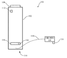
도 1은 극저온 처리 시스템의 일 실시예의 개략도이다.
도 2는 극저온 처리 시스템의 어플리케이터의 일 실시예의 측면도이다.
도 3은 어플리케이터의 헤드 부분의 양태들의 측면 확대도이다.
도 4는 세장 부재(elongate member)를 포함하는 노즐의 정면 확대도이다.
도 5는 노즐 및 구멍들의 선형 어레이를 포함하는 세장 부재의 일 실시예의 저면도이다.
도 6은 노즐의 세장 부재 상에 위치된 균일하게 이격된 구멍들의 선형 어레이의 일 실시예의 개략도이다.
도 7은 노즐의 세장 부재 상에 위치된 엇갈린 구멍들의 선형 어레이의 일 실시예의 개략도이다.
도 8은 환자의 피부에 대한 극저온제의 적용의 일 실시예의 개략도이다.
도 9는 바퀴 달린 스페이서의 일 실시예의 사시도이다.
도 10은 슬라이더 스페이서의 일 실시예의 사시도이다.
도 11은 극저온제 스프레이를 적용함으로써 환자의 피부를 냉각시키는 프로세스의 일 실시예를 도시하는 흐름도이다.1 is a schematic diagram of one embodiment of a cryogenic processing system.
2 is a side view of one embodiment of an applicator of a cryogenic processing system.
3 is an enlarged side view of aspects of the head portion of the applicator.
4 is an enlarged front view of a nozzle including an elongate member.
5 is a bottom view of one embodiment of an elongate member that includes a linear array of nozzles and holes.
6 is a schematic diagram of one embodiment of a linear array of uniformly spaced holes located on an elongate member of a nozzle.
7 is a schematic diagram of one embodiment of a linear array of staggered holes located on an elongate member of a nozzle.
8 is a schematic of one embodiment of the application of a cryogenic agent to the skin of a patient.
9 is a perspective view of one embodiment of a wheeled spacer.
10 is a perspective view of one embodiment of a slider spacer.
11 is a flow diagram illustrating one embodiment of a process for cooling a patient's skin by applying a cryogenic spray.
본 개시의 실시예들은 냉동요법 피부 처리를 제공하기 위한 시스템들, 방법들 및 디바이스들에 관한 것이다. 일부 실시예들에서, 이들은 원하는 피부 처리, 예컨대 피부 미백 또는 저색소침착을 실행하기 위해 동결 조직의 라인(a line of frozen tissue)을 생성하는 평면 방식(planar manner)으로 피부를 향해 극저온제 또는 냉기체를 지향시키기 위한 구멍들의 선형 어레이를 포함하는 노즐을 이용하는 냉동 스프레이 어플리케이터를 포함할 수 있다. 구멍들의 선형 어레이는 구멍들의 단일 열 또는 구멍들의 복수의 열로 배열될 수 있다. 이러한 선형 어레이 노즐 설계는 피부 표면상에 부딪히도록 극저온제 또는 냉기체의 커튼 적용을 지향시킬 수 있고, 이는 바람직하지 않은 부작용 없이 환자의 피부의 큰 처리 영역들에 대한 냉각 처리의 균일하고 제어된 적용을 용이하게 할 수 있다.Embodiments of the present disclosure relate to systems, methods, and devices for providing cryotherapy skin treatment. In some embodiments, they are cryogenic or cold directed towards the skin in a planar manner that creates a line of frozen tissue to perform the desired skin treatment, such as skin whitening or hypopigmentation. It may include a refrigeration spray applicator using a nozzle comprising a linear array of holes for directing gas. The linear array of holes can be arranged in a single row of holes or a plurality of rows of holes. This linear array nozzle design can direct curtain application of cryogenic or cold air to impinge on the skin surface, which ensures uniform and controlled cooling of large treatment areas of the patient's skin without undesirable side effects. Application can be facilitated.
본 발명의 미세 튜닝된 선형 어레이 노즐 설계는 단일 개구 또는 개구들의 클러스터를 종종 포함하는 전통적인 스프레이 노즐 설계들에 비해 이점들을 제공한다. 예를 들어, 단일 개구는 제한된 처리 영역을 가지며, 영역 위에 분무될 때 균일한 냉각 처리를 제공하기가 어렵다. 개구들의 클러스터는 더 큰 처리 영역을 제공할 수 있지만, 개구들의 클러스터는 바람직하지 않게 환자의 피부에 대한 극저온제 또는 냉기체 스프레이의 강도를 증가시켜 피부 상의 바람직하지 않은 폭파( blasting) 및 제어의 결여를 유발할 수 있다. 전통적인 노즐 설계들은 또한 피부 조직의 큰 영역들에 걸쳐 신뢰할 수 있고 일관된 냉동 스프레이 투여량을 제공하는 것의 어려움을 증가시킬 수 있다. 대조적으로, 본 개시의 노즐들은 피부 처리의 라인을 생성하는 평면 방식으로 피부의 넓은 영역들을 향해 극저온제 또는 냉기체의 균일하고 동등한 전달을 용이하게 하기 위한 구멍들의 선형 어레이를 포함한다. 이러한 선형 커버리지(linear coverage)는 피부에 극저온제의 제어되고 일관된 투여량을 전달하면서 피부에 대한 노즐의 스위핑을 용이하게 한다.The fine tuned linear array nozzle design of the present invention provides advantages over traditional spray nozzle designs that often include a single opening or a cluster of openings. For example, a single opening has a limited treatment area and it is difficult to provide a uniform cooling treatment when sprayed over the area. The cluster of openings may provide a larger treatment area, but the cluster of openings undesirably increases the strength of the cryogenic or cold air spray on the patient's skin, resulting in undesirable blasting and lack of control on the skin. May cause. Traditional nozzle designs can also increase the difficulty of providing reliable and consistent frozen spray dosages over large areas of skin tissue. In contrast, the nozzles of the present disclosure include a linear array of holes to facilitate uniform and equal delivery of cryogenic or cold air towards large areas of the skin in a planar manner creating a line of skin treatment. This linear coverage facilitates sweeping of the nozzle to the skin while delivering a controlled and consistent dose of cryogenic agent to the skin.
노즐은 구멍들의 선형 어레이 내의 구멍들의 일부 또는 전부의 폐색(obstruction)을 방지하고/하거나, 분배되는 극저온제 내의 원치 않는 양의 수분의 혼입을 방지하기 위한 특징들을 포함하고/하거나, 방지하도록 제어될 수 있다. 이러한 특징들은 노즐의 일부일 수 있는 덮개를 포함할 수 있다. 덮개는 구멍들의 선형 어레이 주위에서 완전히 또는 부분적으로 연장될 수 있다. 일부 실시예들에서, 덮개는 구멍들에서 얼음 결정들이 형성될 가능성을 감소시키며, 그렇게 함으로써 구멍들을 통한 극저온제의 흐름을 차단할 수 있다.The nozzle may be controlled to include and / or be controlled to prevent obstruction of some or all of the holes in the linear array of holes and / or to prevent the incorporation of unwanted amounts of moisture in the cryogenic agent dispensed. Can be. Such features may include a lid that may be part of a nozzle. The cover may extend fully or partially around the linear array of holes. In some embodiments, the cover reduces the likelihood of ice crystals forming in the holes, thereby blocking the flow of cryogenic agent through the holes.
노즐은 보호 기체가 분배될 수 있는 하나 또는 여러 개의 구멍을 더 포함할 수 있다. 일부 실시예들에서, 이러한 보호 기체는 극저온제 내의 주위 수분의 혼입을 방지하고 스프레이 또는 극저온제 동안 또는 그 후에 노즐 표면의 결빙을 방지하기 위해 극저온제가 그를 통해 또는 그 안으로 분배될 수 있는 보호 커튼을 형성할 수 있다. 보호 기체는 극저온제의 전달 전 또는 후에 보호 기체를 전달함으로써 극저온제가 분배되는 것들과 동일한 구멍들 또는 어플리케이터로부터 분배될 수 있거나, 보호 기체는 극저온제가 분배되는 것들과 다른 별개의 구멍들로부터 전달될 수 있다. 일부 실시예들에서, 보호 기체는 질소, 이산화탄소, 헬륨, 수소, 네온, 산소, 불소, 아르곤, 메탄, 냉매 및/또는 공기일 수 있다. 일부 실시예들에서, 보호 기체는 불활성 기체일 수 있다.The nozzle may further comprise one or several holes through which the protective gas can be dispensed. In some embodiments, such a protective gas may be provided with a protective curtain through which the cryogenic agent may be dispensed through or into it to prevent incorporation of ambient moisture in the cryogenic agent and to prevent freezing of the nozzle surface during or after spraying or cryogenic agent. Can be formed. The protective gas may be dispensed from the same holes or applicators as those to which the cryogen is dispensed by delivering the protective gas either before or after delivery of the cryogen, or the protective gas may be delivered from separate holes other than those to which the cryogen is dispensed. have. In some embodiments, the protective gas may be nitrogen, carbon dioxide, helium, hydrogen, neon, oxygen, fluorine, argon, methane, refrigerant and / or air. In some embodiments, the protective gas can be an inert gas.
이제, 도 1을 참조하면, 극저온 처리 시스템(100)의 일 실시예가 도시되어 있다. 극저온 처리 시스템(100)은 극저온제를 포함하고/하거나 전달할 수 있다. 이 극저온제는 일부 실시예들에서 액화 기체(liquefied gas), 예컨대 액체 헬륨, 액체 수소, 액체 네온, 액체 산소, 액화 불소, 액화 아르곤, 액화 메탄, 액화 공기 등을 포함할 수 있다. 일부 실시예들에서, 극저온제는 예를 들어 냉각된 또는 차가운 공기와 같은 냉각된 또는 차가운 기체를 포함할 수 있다. 일부 실시예들에서, 탱크 내의 극저온제는 액체 및 기체의 혼합물, 예컨대 액체 및 기체의 극저온제일 수 있거나, 달리 말하면 부분적으로 액체일 수 있다. 극저온 처리 시스템(100)은 본 명세서에서 컨테이너(102), 극저온제 소스(102) 또는 캐니스터(canister, 102)로도 지칭되는 탱크(102)를 포함할 수 있다. 탱크(102)는 다양한 형상 및 크기를 포함할 수 있고, 다양한 재료로 제조될 수 있다. 일부 실시예들에서, 탱크(102)는 극저온제를 포함할 수 있고/있거나 가압된 극저온제를 포함할 수 있는 내부 볼륨을 정의하는 금속 실린더를 포함할 수 있다. 일부 실시예들에서, 금속 실린더는 알루미늄 또는 스틸로 제조될 수 있다.Referring now to FIG. 1, one embodiment of a
일부 실시예들에서, 탱크(102)는 히터(104), 온도조절기(thermostat, 106) 및/또는 제어기(108)를 포함할 수 있다. 히터(104)는 탱크(102) 및/또는 탱크(102)에 포함된 극저온제를 원하는 온도로 그리고/또는 탱크(102)에 포함된 극저온제가 원하는 압력에 도달할 때까지 가열할 수 있는 임의의 원하는 히터를 포함할 수 있다. 원하는 압력은 일부 실시예들에서 100 psi 미만, 500 psi 미만, 1,000 psi 미만, 2,000 psi 미만, 5,000 psi 미만, 0 내지 2,000 psi 사이, 500 내지 1,500 psi 사이, 약 1,000 psi 또는 임의의 다른 또는 중간 압력일 수 있다. 일부 실시예들에서, 히터(104)는 탱크(102)의 바닥(110)에 또는 그 위에 그리고/또는 탱크(102)의 바닥(110)에 근접하여 위치될 수 있다. 일부 실시예들에서, 탱크(102) 상의 그리고/또는 탱크(102) 내의 히터(104)의 이러한 위치는 탱크(102) 내에 포함된 극저온제의 가열 및 특히 탱크 내에 포함된 극저온제의 액체 부분의 가열을 용이하게 할 수 있다.In some embodiments,
온도조절기(106)는 탱크(102) 내의 온도를 측정하도록 구성된 하나 또는 여러 개의 특징을 포함할 수 있다. 이들은, 예를 들어 하나 또는 여러 개의 열전쌍(thermocouples), 서미스터(thermistors), 온도계(thermometers) 등을 포함할 수 있다. 온도조절기(106)는 탱크(102) 상의 임의의 원하는 위치에 위치될 수 있고, 일부 실시예들에서는 히터(104)에 근접하게 위치될 수 있다.
제어기(108)는 히터(104) 및/또는 온도조절기(106)와 통신 결합(communicatively coupled)될 수 있다. 일부 실시예들에서, 제어기(108)는 탱크(102) 및/또는 극저온제의 하나 또는 여러 개의 속성, 예컨대 탱크(102) 내의 압력, 탱크(102) 내의 극저온제의 양, 극저온제 또는 탱크(102)의 온도 등을 디스플레이하는 하나 또는 여러 개의 특징을 포함할 수 있다. 제어기(108)는 하나 또는 여러 개의 특징을 추가로 포함할 수 있고, 이에 따라 설정 포인트 정보가 사용자에 의해 제어기에 제공될 수 있고/있거나 설정 포인트들이 변경될 수 있다.The
제어기(108)는 히터(104) 및/또는 온도조절기(106)와의 통신 결합을 통해, 극저온제 및/또는 탱크(102)의 온도를 제어할 수 있다. 일부 실시예들에서, 예를 들어, 제어기는 온도조절기(106)로부터 극저온제 및/또는 탱크(102)의 온도를 나타내는 하나 또는 여러 개의 신호를 수신할 수 있다. 제어기는 신호들을 설정 포인트 정보와 비교할 수 있고, 극저온제 및/또는 탱크(102)의 온도를 증가 또는 감소시킬지를 결정할 수 있다. 예를 들어 히터(104)의 전력 공급을 제어함으로써, 예를 들어 히터(104)로 가는 전류의 양을 제어함으로써, 극저온제 및/또는 탱크의 온도를 제어한다. 일부 실시예들에서, 제어기(108), 히터(104) 및 온도조절기(106)는 극저온제를 분배하는 동안 탱크(102)를 충분히 가열하여 일정한 압력 및/또는 온도를 유지할 수 있다.The
탱크(102)는 스위치(112), 예컨대 안전 스위치를 포함할 수 있다. 일부 실시예들에서, 안전 스위치는 제어기(108) 및/또는 히터(104)와 통신 결합될 수 있다. 일부 실시예들에서, 스위치(112)의 조작은 탱크(102) 및/또는 탱크(102) 내의 극저온제의 임의의 추가의 가열을 방지하기 위해 히터(104)에 대한 전력을 차단할 수 있다. 일부 실시예들에서, 스위치(112)는 제어기(108)와 별개일 수 있고, 일부 실시예들에서, 스위치(112)는 제어기(108)에 통합될 수 있다.
극저온 처리 시스템(100)은 본 명세서에서 냉동 스프레이 어플리케이터(114)로도 지칭되는 어플리케이터(114)를 포함할 수 있고, 이 어플리케이터(114)는 본 명세서에서 구멍들의 선형 어레이를 포함할 수 있는 노즐 조립체(116)로도 지칭되는 노즐(116)을 포함할 수 있다. 일부 실시예들에서, 냉동 스프레이 어플리케이터(114)는 어플리케이터(114)의 노즐(116) 또는 다른 부분이 환자의 피부와 접촉하여 환자의 피부를 냉각시키는 것이 아니라, 오히려 극저온제가 노즐(116)에 의해 환자의 피부로 분배되어 환자의 피부를 냉각시킨다는 점에서 비접촉 냉동 스프레이 어플리케이터일 수 있다.
어플리케이터(114) 및 특히 노즐(116)은 극저온제를 탱크(102)로부터 환자의 피부로 분배할 수 있다. 일부 실시예들에서, 어플리케이터(114)는 본 명세서에서 호스(118), 공급 튜브(118) 또는 연결 튜브(118)로도 지칭되는 튜브(118)를 통해 탱크(102)와 유동적으로 연결될 수 있다. 일부 실시예들에서, 튜브(118)는 탱크를 통해 연장되는 포트 또는 애퍼처를 통해 탱크의 내부 볼륨과 유동적으로 연결될 수 있다. 일부 실시예들에서, 튜브(118)는 탱크(102)의 바닥(110)에서 또는 그 근처에서 탱크(102)에 연결될 수 있다. 탱크(102)의 바닥(110)에서의 또는 그 근처에서의 튜브(118)의 연결은 극저온제의 인출 및 특히 튜브(118) 내로의 액체 극저온제의 인출과, 극저온제의 전달 및 특히 어플리케이터(114) 및 노즐(116)로의 액체 극저온제의 전달을 용이하게 할 수 있다.The
튜브(118)는 다양한 형상 및 크기를 포함할 수 있고, 다양한 재료로 제조될 수 있다. 일부 실시예들에서, 튜브는 극저온제의 온도 및/또는 압력을 견딜 수 있고/있거나 극저온제에 견딜 수 있는 재료로 제조될 수 있다. 일부 실시예들에서, 튜브(118)는 노즐(116) 및/또는 어플리케이터(114)에서의 극저온제의 압력이 탱크(102)에서와 동일하거나 실질적으로 동일하게 하는 직경, 형상 및/또는 링크를 가질 수 있다. 본 명세서에서 사용되는 바와 같이, 실질적 또는 대략적이라는 것은 이들과 관련된 값 또는 값들로부터 10%, 5%, 2% 또는 1% 미만만큼 벗어나는 값을 지칭한다. 따라서, 노즐(116) 및/또는 어플리케이터(114)에서의 극저온제의 압력은 노즐(116) 및/또는 어플리케이터(114)에서의 극저온제의 압력이 탱크(102) 내의 극저온제의 압력으로부터 10%, 5%, 2% 또는 1% 미만만큼 벗어날 때 탱크(102)에서와 동일하거나 또는 실질적으로 동일하다.
도 2는 노즐(116)을 포함하는 어플리케이터(114)의 일 실시예의 측면도이다. 어플리케이터(114)는 다양한 형상 및 크기를 포함할 수 있고, 다양한 재료로 제조될 수 있다. 일부 실시예들에서, 어플리케이터(114)는 핸드헬드 어플리케이터(114)일 수 있고, 다른 실시예들에서, 어플리케이터(114)는 자동화 시스템 또는 디바이스, 예컨대 로봇 시스템 또는 디바이스, 원격 조종 시스템(teleoperated system) 또는 디바이스 등의 일부일 수 있다.2 is a side view of one embodiment of an
어플리케이터(114)는 핸들 부분(200) 및 헤드 부분(202)을 포함할 수 있다. 핸들 부분(200)은 헤드 부분(202)에 연결된 그립(204)을 포함할 수 있다. 그립(204)은 어플리케이터(114)의 조작자의 손에 파지되도록 크기 설정되고 형상화될 수 있다. 헤드 부분(202)은 노즐(116)에 연결될 수 있고, 특히 노즐 베이스(208)를 통해 노즐(116)의 노즐 튜브(206)로도 본 명세서에서 지칭되는 세장 부재(206)에 결합될 수 있다. 일부 실시예들에서, 노즐 베이스(208)는, 예를 들어 NPT 나사형 플러그와 같은 나사형 플러그를 포함할 수 있다. 노즐 베이스(208)는 예를 들어 황동, 스틸, 스테인리스 스틸, 니켈, 니켈 합금 등을 포함하는 다양한 재료로 제조될 수 있다.
도 2에 도시된 바와 같이, 튜브(118)는 그립(204)을 따라 연장될 수 있고, 결합부(210)에서 헤드 부분(202)에 결합될 수 있다. 결합부(210)는, 예를 들어 암호스 결합부(female hose coupling)를 포함할 수 있는 예를 들어 호스 결합기(hose coupler, 212)를 포함할 수 있다. 호스 결합기(212)는 헤드 결합기(214)와 나사 방식으로 맞물릴 수 있고, 헤드 결합기(214)는, 예를 들어 나사형 결합부(threaded coupling)일 수 있다. 일부 실시예들에서와, 도 2에 도시된 바와 같이, 헤드 결합기(214)는 어플리케이터(114)의 헤드 부분(202)의 특징들과 나사 방식으로 맞물려서 헤드 결합기(214)가 헤드 부분(202)에 결합된다.As shown in FIG. 2, the
어플리케이터(114)는 필터(216)를 포함할 수 있다. 필터(216)는 다양한 형상 및 크기를 포함할 수 있고, 다양한 재료로 제조될 수 있다. 필터(216)는 어플리케이터(114) 및/또는 튜브(118) 전체에 걸쳐 다수의 위치에 위치될 수 있다. 일부 실시예들에서, 필터(216)는 튜브(118)와 노즐(116) 사이에, 노즐(116) 내에, 예를 들어 노즐 베이스(208) 내에, 결합부(210) 내에, 예를 들어 헤드 결합기(214) 내에, 기타 등등에 위치될 수 있다.
필터(216)는 노즐(116)에서의 막힘을 제거 및/또는 최소화하도록 크기 설정될 수 있다. 일부 실시예들에서, 필터(216)는 1μ 필터, 10μ 필터, 25μ 필터, 50μ 필터, 100μ 필터, 10μ 내지 100μ 사이의 필터, 40μ 내지 50μ 사이의 필터, 약 50μ 필터 또는 임의의 다른 원하는 필터일 수 있다. 일부 실시예들에서, 필터(216)는 세라믹 필터, 중합체 필터, 소결 금속 필터, 또는 임의의 다른 원하는 필터 유형을 포함할 수 있다. 일부 실시예들에서, 필터(216)는 소결 스테인리스 스틸 필터 또는 메시 스크린을 포함할 수 있다.
어플리케이터(114)의 헤드 부분(202)은 노즐(116)로의 극저온제의 흐름 및/또는 노즐(116)로부터의 극저온제의 분배를 제어할 수 있는 밸브(218)를 포함할 수 있다. 밸브(218)는 일부 실시예들에서, 예를 들어 버튼일 수 있는 제어 특징(220)에 의해 제어될 수 있다. 일부 실시예들에서, 예를 들어, 제어 특징(220)의 조작은 밸브(218)의 개방 또는 폐쇄를 유발할 수 있고, 따라서 극저온제의 분배의 개시 또는 종료를 유발할 수 있다. 어플리케이터(114)의 헤드 부분(202)은, 일부 실시예들에서 충전재 플러그(filler plug, 222)를 포함할 수 있다. 일부 실시예들에서, 충전재 플러그(222)는 데드 볼륨 충전재 플러그(dead volume filler plug)를 포함할 수 있고, 노즐(116)에 근접하여, 특히 노즐 베이스(208)에 근접하여 헤드 부분(202)의 공급 채널(224) 내에 위치될 수 있다. 일부 실시예들에서, 공급 채널(224)은 어플리케이터의 헤드 부분(202)의 적어도 일부를 통해 연장될 수 있다. 일부 실시예들에서, 밸브(218)는 노즐(116)에 극저온제를 제공하고/하거나 극저온제를 노즐(116)로부터 분배하기 위해 충전재 플러그(222)와 상호작용한다.
도 3의 측면 확대도 및 도 4의 정면 확대도에 도시된 바와 같이, 노즐의 세장 부재(206)는 세장 부재(206)의 벽들(402)에 의해 정의된 내부 볼륨(400)을 포함한다. 일부 또는 전부가 원통형 애퍼처 또는 원통형 개구를 포함할 수 있고, 따라서 원통형 구멍들(cylindrical orifices, 404)일 수 있는 복수의 구멍(404)이 세장 부재(206)의 벽들(402)을 통해 연장되어 세장 부재(206)의 내부 볼륨(400)을 세장 부재(206)의 외부에 유동적으로 결합한다. 구체적으로, 구멍들(404)은 세장 부재(206)의 내부 볼륨(400)과 접촉하는 근위 개구(proximal opening, 406)로부터 원위 개구들(distal openings, 408)로 연장된다. 도 4에 도시된 바와 같이, 노즐 베이스(208)를 통해 연장되는 채널(500)은 세장 부재(206)의 내부 볼륨(400)과 유동적으로 연결된다. 채널(500)은 또한 튜브(118)와 그리고/또는 밸브(218) 또는 충전 플러그(222)와 유동적으로 연결될 수 있다.As shown in the side enlarged view of FIG. 3 and the front enlarged view of FIG. 4, the
일부 실시예들에서, 구멍들(404)은 각각 동일한 또는 대략 동일한 직경 및/또는 깊이를 가질 수 있고, 일부 실시예들에서, 구멍들(404)의 일부 또는 전부는 상이한 직경들 및/또는 깊이들을 가질 수 있다. 일부 실시예들에서, 구멍들(404)은 구멍들(404)을 통과하는 극저온제의 팽창이 거의 단열 팽창이 되도록 크기 설정되고 형상화될 수 있다. 일부 실시예들에서, 예를 들어, 각각의 구멍(404)은: 약 0.001 인치, 약 0.005 인치, 약 0.007 인치, 약 0.008 인치, 약 0.01 인치, 약 0.02 인치, 약 0.05 인치, 약 0.08 인치, 약 0.1 인치, 약 0.001 내지 0.01 인치 사이, 약 0.005 내지 0.008 인치 사이의 직경 또는 임의의 다른 또는 중간 직경을 가질 수 있다. 일부 실시예들에서, 구멍들은 약 0.001 인치, 약 0.005 인치, 약 0.008 인치, 약 0.01 인치, 약 0.02 인치, 약 0.05 인치, 약 0.08 인치, 약 0.1 인치, 약 0.5 인치, 약 0.001 내지 0.05 인치 사이, 약 0.005 내지 0.02 인치 사이의 깊이 및/또는 임의의 다른 또는 중간 깊이를 가질 수 있다.In some embodiments, the
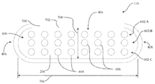
일부 실시예들에서와, 도 5 내지 7에 도시된 바와 같이, 복수의 구멍(404)은 구멍들(404)의 선형 어레이(600)로 배열될 수 있다. 구멍들(404)의 이러한 어레이(600)는, 예를 들어 3개의 구멍, 5개의 구멍, 8개의 구멍, 10개의 구멍, 11개의 구멍, 15개의 구멍, 20개의 구멍, 30개의 구멍, 50개의 구멍, 100개의 구멍, 0 내지 100개 사이의 구멍, 0 내지 50개 사이의 구멍, 0 내지 25개 사이의 구멍, 0 내지 11개 사이의 구멍 또는 임의의 다른 또는 중간 수의 구멍을 포함할 수 있다. 일부 실시예들에서, 선형 어레이(600)는 약 10 인치, 약 5 인치, 약 2 인치, 약 1 인치, 약 0.5 인치, 0 내지 10 인치 사이, 0 내지 5 인치 사이, 0 내지 2 인치 사이의 길이 또는 임의의 다른 또는 중간 길이를 가질 수 있다. 일부 실시예들에서, 노즐들 각각은: 약 1 인치, 약 0.5 인치, 약 0.1 인치, 약 0.05 인치, 약 0.01 인치, 0 내지 1 인치 사이, 0 내지 0.5 인치 사이, 0 내지 0.2 인치 사이의 거리 또는 임의의 다른 또는 중간 거리만큼 분리될 수 있다.In some embodiments and as shown in FIGS. 5-7, the plurality of
일부 실시예들에서, 구멍들의 선형 어레이를 형성하는 복수의 구멍(404)은 도 5에 도시된 바와 같은 구멍들의 단일 열로 또는 구멍들(404)의 복수의 열(602-A, 602-B, 602-C)로 배열될 수 있다. 일부 실시예들에서, 선형 어레이(600)는 구멍들의 1개의 열, 구멍들의 2개의 열, 구멍들의 3개의 열, 구멍들의 5개의 열, 구멍들의 7개의 열, 구멍들의 10개의 열, 구멍들의 20개의 열, 구멍들의 1 내지 10개사이의 열 또는 임의의 다른 또는 중간 수의 구멍들의 열을 포함할 수 있다. 일부 실시예들에서, 구멍들(404)의 열들(602-A, 602-B, 602-C) 각각은 동일한 수의 구멍(404)을 가질 수 있고, 일부 실시예들에서, 구멍들(404)의 열들(602-A, 602-B, 602-C)의 일부 또는 전부는 상이한 수의 구멍을 가질 수 있다. 선형 어레이(600)가 구멍들(404)의 다수의 열을 포함하는 실시예들에서, 상이한 열들 내의 구멍들(404)은 도 6에 도시된 바와 같이 정렬될 수 있거나, 구멍들은 도 7에 도시된 바와 같이 엇갈릴 수 있다. 일부 실시예들에서, 구멍들(404)의 상이한 열들 내의 구멍들(404)은 동일한 크기 또는 치수를 가질 수 있고, 일부 실시예들에서, 구멍들은 상이한 크기 또는 치수를 가질 수 있다. 일부 실시예들에서, 선형 어레이(600) 내의 구멍들(404)의 일부 또는 전부는 동일하게 그리고/또는 균일하게 이격될 수 있고, 일부 실시예들에서, 선형 어레이(600) 내의 구멍들(404)의 일부 또는 전부는 동일하지 않게 이격되고/되거나 엇갈릴 수 있다.In some embodiments, the plurality of
일부 실시예들에서, 복수의 구멍(404)의 일부 또는 전부는 극저온제를 분배할 수 있고, 일부 실시예들에서, 복수의 구멍(404)의 일부 또는 전부는 보호 기체, 예컨대 불활성 기체를 분배할 수 있다. 일부 실시예들에서, 이러한 불활성 기체는 원하는 물 함량, 예를 들어 10 중량%(% water by weight) 미만, 5 중량% 미만, 1 중량% 미만, 0.1 중량% 미만, 0.05 중량% 미만, 0.01 중량% 미만, 0.005 중량% 미만, 0.001 중량% 미만 또는 임의의 다른 또는 중간 값의 물 함량을 가질 수 있다. 이러한 보호 기체는 극저온제 내의 주변 수분의 혼입을 방지하도록 극저온제가 분배될 수 있는 보호 커튼을 형성할 수 있다. 일부 실시예들에서, 예를 들어 극저온제 내의 주변 수분의 혼입은 극저온제의 온도, 및/또는 피부 또는 피부에서의 극저온제의 온도를 제어하는 능력에 악영향을 미칠 수 있다. 혼입된 수분은 어플리케이터(114)의 동작에 유해할 수 있는데, 이는 혼입된 수분이 하나 또는 여러 개의 구멍(404)을 차단하고 극저온제의 적절한 분배를 방해할 수 있기 때문이다. 또한, 혼입된 수분은 혼입된 수분으로부터 형성된 얼음 결정들의 축적으로부터 피부 상에 "눈(snow)" 층을 생성할 수 있다. 이러한 얼음 층은 피부를 절연시킬 수 있고, 피부에 대한 원하는 처리의 제공을 방해할 수 있다.In some embodiments, some or all of the plurality of
보호 기체는 극저온제의 전달 전에 보호 기체를 전달함으로써 극저온제가 분배되는 것들과 동일한 구멍들(404)로부터 분배될 수 있거나, 보호 기체는 극저온제가 분배되는 것들과 다른 본 명세서에서 커튼 애퍼처들(604) 또는 커튼 개구들(604)로도 지칭되는 커튼 구멍들(604)과 같은 별개의 구멍들(404)로부터 전달될 수 있다. 본 명세서에서 사용되는 바와 같이, 커튼 구멍(604)은 보호 기체가 전달되는 구멍(404)을 지칭하고, 본 명세서에서 극저온제 애퍼처(606) 또는 극저온제 개구(606)로도 지칭되는 극저온제 구멍(606)은 극저온제가 전달되는 구멍(404)을 지칭한다. 일부 실시예들에서, 복수의 커튼 구멍(604)은 커튼 구멍들(604)의 어레이를 생성할 수 있고, 복수의 극저온제 구멍(606)은 극저온제 구멍들(606)의 어레이를 생성할 수 있다.The protective gas may be dispensed from the
일부 실시예들에서, 예를 들어, 구멍들(404)의 열들(602-A, 602-B, 602-C) 중 하나 이상이 극저온제의 전달을 위해 선택될 수 있고, 구멍들(404)의 열들(602-A, 602-B, 602-C) 중 하나 이상이 보호 기체의 전달을 위해 선택될 수 있다. 일 실시예에서, 예를 들어, 구멍들(404) 중 하나 또는 여러 개 및/또는 구멍들(404)의 열들(602-A, 602-B, 602-C) 중 하나 또는 여러 개가 극저온제의 전달과 동시에 또는 부분적으로 동시에 보호 기체의 전달을 위해 선택된다. 이러한 일 실시예에서, 예를 들어, 열들(602-A 및 602-C) 중 하나 또는 둘 모두 내의 구멍들(404)의 일부 또는 전부는 열(604-B)에 위치할 수 있는 하나 또는 여러 개의 극저온제 구멍으로부터의 극저온제의 전달과 동시에 또는 부분적으로 동시에 보호 기체를 전달하도록 구성된 커튼 구멍들(603)일 수 있다. 일부 실시예들에서, 커튼 구멍들(604)은 극저온제 구멍들(606) 주위에 둘레를 형성하도록 위치될 수 있다. 그러한 실시예에서, 열들(602-A 및 602-C) 내의 구멍들(404)은 커튼 구멍들(604)이고, 또한 노즐 튜브(206)의 제1 단부(806)에 가장 근접한 열(602-B) 내의 구멍(404) 및 노즐 튜브(206)의 제2 단부(808)에 가장 근접한 열(602-B) 내의 구멍(404)은 커튼 구멍들이다.In some embodiments, for example, one or more of the rows 602 -A, 602-B, 602-C of the
일부 실시예들에서, 구멍들(404)의 일부 또는 전부는 가열된 기체를 전달할 수 있다. 일부 실시예들에서, 예를 들어 극저온제 및 가열된 기체는 선택적으로 환자의 피부의 온도를 순환(cycle)시키도록 전달될 수 있다. 일부 실시예들에서, 가열된 기체는 극저온제가 전달되는 구멍들(404)과 다른 구멍들(404)을 통해 전달될 수 있고, 일부 실시예들에서, 가열된 기체는 극저온제가 전달되는 것들과 동일한 구멍들(404)을 통해 전달될 수 있다.In some embodiments, some or all of the
노즐(116)은 구멍들(404) 중 하나 또는 여러 개를 차단할 수 있는 덮개(700)를 추가로 포함할 수 있다. 일부 실시예들에서, 예를 들어, 덮개(700)는 복수의 구멍(404)을 습한 공기와의 접촉으로부터 그리고/또는 구멍들(404) 중 하나 또는 여러 개를 차단할 수 있는 얼음 결정들의 형성으로부터 차단하도록 크기 설정되고 형상화될 수 있다. 구체적으로, 일부 실시예들에서, 덮개(700)는 구멍들의 외부 및/또는 원위 개구들에서 정체 구역을 생성할 수 있다. 일부 실시예들에서, 덮개(700)는 노즐 튜브(206)와 동일한 재료를 포함할 수 있고, 일부 실시예들에서, 덮개(700)는 노즐 튜브(706)와 상이한 재료를 포함할 수 있다. 일부 실시예들에서, 예를 들어, 덮개는 노즐 튜브(706)의 재료보다 더 낮은 열 전도율을 갖는 재료를 포함할 수 있거나, 구체적으로, 일부 실시예들에서, 노즐 튜브(706)는 예를 들어 스틸, 스테인리스 스틸, 니켈 또는 니켈 합금, 알루미늄 또는 황동과 같은 금속을 포함할 수 있고, 덮개(700)는 중합체를 포함할 수 있다.The
덮개(700)는 구멍들(404)의 선형 어레이(600) 주위에서 전체적으로 또는 부분적으로 연장될 수 있다. 일부 실시예들에서, 덮개는 구멍들(404)의 선형 어레이(600) 주위에서 연장되는 직사각형 또는 타원형 애퍼처(702)를 포함한다. 애퍼처(702)는 폭(704), 깊이, 및 길이(706)를 가질 수 있다. 일부 실시예들에서, 덮개(700)는 대략적으로: 구멍들(404)의 직경의 1배, 구멍들(404)의 직경의 2배, 구멍들(404)의 직경의 3배, 구멍들(404)의 직경의 5배, 구멍들(404)의 직경의 10배, 구멍들(404)의 직경의 1배 내지 10배 사이, 구멍들(404)의 직경의 1배 내지 4배 사이의 깊이 또는 임의의 다른 또는 중간 깊이를 가질 수 있다.The
도 8은 환자의 피부에 대한 극저온제의 적용의 일 실시예의 개략도이다. 도시된 바와 같이, 냉동 스프레이 어플리케이터(114)는 처리될 환자의 피부 조직(300)으로도 본 명세서에서 지칭되는 피부(300)의 일부에 근접한 위치에 위치될 수 있다. 어플리케이터(114)는 어플리케이터(114)의 노즐(116) 내의 구멍들(404)의 선형 어레이(600)를 통해 액체 극저온제 또는 냉기체이거나 이를 포함할 수 있는 극저온제의 선형 커튼으로도 본 명세서에서 지칭되는 평면 스프레이(302)를 지향시키도록 제어될 수 있다. 일부 실시예들에서, 평면 스프레이는 극저온제 연무(mist), 예컨대 액체 극저온제 연무를 포함하고, 일부 실시예들에서, 액체 극저온제는 액체 이산화탄소를 포함할 수 있다. 이러한 액체 극저온제 또는 냉기체는 냉각 처리의 라인에서 환자의 피부 조직(300)의 영역(304)을 냉각시켜 피부(300)의 처리를 실행할 수 있다. 일부 실시예들에서, 평면 스프레이(302)는 -4℃ 내지 -80℃ 사이의 피부 표면에서의 온도를 가질 수 있다.8 is a schematic of one embodiment of the application of a cryogenic agent to the skin of a patient. As shown, the
어플리케이터(114)는 화살표(306)로 표시된 바와 같이 화살표(306)로 표시된 방향으로 이동될 수 있고, 이는 화살표(308)로 표시된 바와 같이 화살표(308)로 표시된 방향으로의 영역(304)의 이동을 유발할 수 있다. 환자의 피부(300)를 가로지르는 이러한 영역(304)의 이동은 어플리케이터(114)가 연속적인 평면 스프레이(302)를 전달할 때 연속적일 수 있거나, 어플리케이터(114)가 예를 들어 평면 스프레이(302)를 간헐적으로 전달하는 것과 같이 비연속적인 평면 스프레이(302)를 전달할 때 중단될 수 있는 처리 영역(310)을 생성할 수 있다.
일부 실시예들에서, 마스크(312)가 극저온제의 전달 전에 피부에 적용되고/되거나 그 위에 놓일 수 있다. 이러한 마스크(312)는 물체(object), 아이템( item) 또는 물질(substance)을 포함할 수 있다. 일부 실시예들에서, 마스크(312)는 천공된 부재, 천공된 필름, 메시 및/또는 온도 제어형 부재를 포함할 수 있다. 일부 실시예들에서는, 예를 들어, 마스크(312)의 온도를 조절하여 피부의 전부 또는 부분들의 온도를 제어할 수 있고, 구체적으로, 일부 실시예들에서 마스크(312)를 가열하여 피부를 가열하고/하거나 피부를 순환 가열할 수 있다. 일부 실시예들에서, 마스크(312)는 어플리케이터(114)에 의해 피부(300) 및/또는 마스크(312)에 적용된 극저온제의 일부로부터 피부(300)를 절연 및/또는 차단함으로써 피부(300)의 온도에 영향을 줄 수 있다.In some embodiments,
일부 실시예들에서, 어플리케이터(114)는 도 9 및 10에 도시된 바와 같이 스페이서, 특히 기계적 스페이서(800)를 추가로 포함할 수 있다. 기계적 스페이서(800)는 노즐(116) 및/또는 구멍들(404) 또는 선형 어레이(600)와 환자의 피부 사이의 원하는, 일정한 그리고/또는 최소의 간격 및/또는 거리를 유지 및/또는 적어도 유지하도록 환자의 피부와 맞물리도록 구성될 수 있다. 기계적 스페이서(800)는 헤드 부분(202) 및/또는 노즐(116)에 결합될 수 있다. 기계적 스페이서(800)는 다양한 형상, 크기 및 설계를 포함할 수 있다. 일부 실시예들에서, 기계적 스페이서(800)는 환자의 피부와 노즐(116) 및/또는 구멍들(404) 또는 선형 어레이(600) 사이의 고정 간격을 유지할 수 있고, 일부 실시예들에서, 기계적 스페이서(800)는 원하는, 일정한 그리고/또는 최소의 간격 및/또는 거리를 변화시키도록 조정 가능할 수 있다.In some embodiments,
기계적 스페이서(800)는 바퀴 달린 스페이서(802)를 포함할 수 있다. 바퀴 달린 스페이서(800)는 예를 들어 1, 2, 3, 4, 6, 8, 10개 또는 임의의 다른 또는 중간 수의 바퀴(804)를 포함하는 하나 또는 여러 개의 바퀴(804)를 포함할 수 있다. 도 8의 실시예에서, 바퀴 달린 스페이서(802)는 제1 바퀴(804-A) 및 제2 바퀴(8004-B)를 포함한다. 제1 바퀴(804-A)는 노즐 튜브(206) 및/또는 선형 어레이(600)의 제1 단부(806)에 근접하게 위치되고, 제2 바퀴(804-B)는 노즐 튜브(206) 및/또는 선형 어레이(600)의 제2 단부(808)에 근접하게 위치된다.
기계적 스페이서(800)는 슬라이더 스페이서(900)를 포함할 수 있다. 슬라이더 스페이서(900)는 예를 들어 1, 2, 3, 4, 6, 8, 10개 또는 임의의 다른 또는 중간 수의 다리(legs, 902)를 포함하는 복수의 다리(902) 또는 갈래(prongs, 902)를 포함할 수 있다. 일부 실시예들에서, 다리들(902)은 노즐(116) 및/또는 구멍들(404)의 선형 어레이(600)와 환자의 피부 사이의 거리를 변화시키기 위해 노즐(116) 및/또는 구멍들(404)의 선형 어레이(600)에 대해 조정 가능할 수 있다.The
이제, 도 11을 참조하면, 환자의 피부를 냉각시키고/시키거나 극저온제를 적용하기 위한 프로세스(1000)의 일 실시예를 예시하는 흐름도가 도시되어 있다. 일부 실시예들에서, 피부는 냉각될 수 있고/있거나 극저온제는 극저온 처리의 일부로서 적용될 수 있다. 일부 실시예들에서, 이러한 처리는 처리된 피부의 색소침착 외관 및/또는 색소침착을 변경할 수 있고, 일부 실시예들에서, 이러한 처리는 처리된 피부의 질감(texture), 팽팽함(tension), 색조(tone), 매끄러움(smoothness) 또는 당김(tightness)을 변경할 수 있다. 일부 실시예들에서, 이러한 극저온 처리는, 예를 들어: 저색소침착 또는 과색소침착; 여드름; 장미증; 건선 등을 포함하는 색소침착 또는 착색 관련 징후들과 같이 큰 피부 영역들에 영향을 줄 수 있는 하나 또는 여러 개의 징후를 처리하는 것일 수 있다. 일부 실시예들에서, 이러한 극저온 처리는 색소침착 관련 잡티들(blemishes)을 포함하는 잡티들을 처리하는 것일 수 있다. 이러한 잡티들은, 기미; 흑색점; 주근깨; 모반, 간반, 검버섯 또는 카페오레 반점을 포함할 수 있다.Referring now to FIG. 11, shown is a flow diagram illustrating one embodiment of a
프로세스는 극저온 처리 시스템(100)의 전부 또는 부분들로 수행될 수 있다. 프로세스(1000)는 블록 1002에서 시작하며, 여기서 마스크(312)가 피부에 적용되고/되거나 피부 상에 배치된다. 마스크가 피부에 적용된 후에, 극저온제 공급기(102)가 프로세스(1000)의 블록 1004에 의해 표시된 바와 같이 가열된다. 일부 실시예들에서, 마스크는 구멍들(404)의 선형 어레이(600)로부터 평면 스프레이를 지향시키기 전에 피부에 적용될 수 있다. 극저온제 공급기(102)는, 예를 들어 액체 및 기체 형태 둘 다일 수 있는 극저온제를 포함할 수 있다. 일부 실시예들에서, 온도조절기(106)로부터 수신된 정보에 따라 제어기(108)에 의해 제어되는 바와 같이 히터(104)에 의해 탱크(102)가 가열될 수 있다. 일부 실시예들에서, 탱크(102)는 원하는 온도로 그리고/또는 탱크(102) 내부의 원하는 압력에 도달할 때까지 가열될 수 있다. 일부 실시예들에서, 탱크(102)는 탱크(102)가 원하는 압력을 유지하도록 가열될 수 있다.The process may be performed in whole or in portions of the
탱크가 가열된 후, 프로세스(1000)의 블록 1006에 지시된 바와 같이, 극저온제, 특히 액체 극저온제가 공급 튜브(118)를 통해 극저온제 공급기(102)로부터 어플리케이터(114)로 운반된다. 일부 실시예들에서, 극저온제는, 예를 들어 밸브(218)의 개구로부터 발생할 수 있는 압력 차이를 통해 튜브(118)를 통해 운반될 수 있다. 일부 실시예들에서, 튜브(118) 내의 액체 극저온제의 압력은 탱크(102) 내의 액체 극저온제의 압력과 동일하고/거나 거의 동일할 수 있다.After the tank is heated, the cryogenic agent, in particular the liquid cryogenic agent, is conveyed from the
프로세스(1000)의 블록 1008에서, 어플리케이터(114)는 환자의 피부에 근접하게 위치된다. 일부 실시예들에서, 환자의 피부에, 특히 처리될 환자의 피부 조직의 영역에 근접하게 냉동 스프레이 어플리케이터(114)를 위치시키는 것은 환자의 피부 조직의 영역에 근접하게 비접촉 냉동 스프레이 어플리케이터(114)를 위치시키거나, 환자의 피부 조직의 영역에 근접하게 기계적 스페이서(800)를 포함하는 냉동 스프레이 어플리케이터(114)를 위치시키는 것을 포함할 수 있다. 일부 실시예들에서, 이것은 어플리케이터를 환자의 피부로부터 원하는 거리에 위치시키는 것을 포함할 수 있고, 이는 예를 들어 기계적 스페이서(800)를 조정하여, 어플리케이터(114)가 기계적 스페이서(800)에 의해 환자의 피부로부터 원하는 거리에 유지되게 하는 것을 포함할 수 있다. 일부 실시예들에서, 기계적 스페이서(800)는 바퀴 달린 스페이서(802) 및/또는 슬라이딩 스페이서(900)를 포함할 수 있다. 일부 실시예들에서, 어플리케이터(114)를 위치시키는 것의 일부로서, 환자의 피부가 기계적 스페이서(800)와 접촉될 수 있다. 일부 실시예들에서, 기계적 스페이서는 어플리케이터(114)와 피부 사이의 미리 결정된 거리를 유지할 수 있다. 일부 실시예들에서, 이러한 미리 결정된 거리는, 예를 들어 1 인치 내지 3 인치 사이 및/또는 0.125 인치 내지 3 인치 사이일 수 있다.In block 1008 of
블록 1010에서, 보호 기체가 전달되어 보호 커튼을 형성한다. 일부 실시예들에서, 보호 커튼의 형성은 불활성 기체 및/또는 건조 기체를 포함할 수 있는 보호 기체의 분배를 포함할 수 있다. 일부 실시예들에서, 보호 기체는 극저온제의 전달 전에, 중에 그리고/또는 후에 전달될 수 있다. 보호 기체는 극저온제가 전달되는 것들과 동일한 구멍들(404)로부터 또는 극저온제가 전달되는 구멍들(404)과 다른 상이한 구멍들(404), 예컨대 하나 또는 여러 개의 커튼 구멍(604)으로부터 전달될 수 있다. 일부 실시예들에서, 이러한 보호 커튼은, 액체 극저온제; 기체 극저온제; 2상 유체; 냉각된 공기; 및/또는 이산화탄소 및/또는 냉기체를 포함할 수 있는 극저온제가 구멍들(404)로부터의 극저온제의 전달로서 구멍들(404)의 하류로 이동할 때 물 혼입 또는 주변 공기 혼입을 방지할 수 있다.At block 1010, a protective gas is delivered to form a protective curtain. In some embodiments, the formation of the protective curtain can include the distribution of a protective gas that can include an inert gas and / or a dry gas. In some embodiments, the protective gas may be delivered before, during and / or after delivery of the cryogenic agent. The protective gas may be delivered from the
블록 1012에서, 극저온제가 어플리케이터(114)로부터 분배, 전달 및/또는 배출되고, 구체적으로 극저온제 또는 냉기체의 평면 스프레이(302)가 냉동 스프레이 어플리케이터(114)의 구멍들(404)의 선형 어레이(600)를 통해 지향된다. 일부 실시예들에서, 이것은 극저온제를 분배 및/또는 배출하기 위한 어플리케이터(114)의 제어를 포함할 수 있다. 일부 실시예들에서, 이것은 예를 들어 어플리케이터(114)로부터의 극저온제의 분배 및/또는 배출을 유발하기 위한 제어 특징(220)의 조작을 포함할 수 있다. 일부 실시예들에서, 극저온제는 노즐(206)로부터, 특히 구멍들(600)의 선형 어레이로부터 분배 및/또는 배출되어 노즐(206)로부터 하류에 극저온제의 선형 커튼을 형성할 수 있다.In block 1012, the cryogenic agent is dispensed, delivered and / or discharged from the
일부 실시예들에서, 구멍들의 선형 어레이를 통해 극저온제 또는 냉기체의 평면 스프레이를 지향시키는 것은 표피를 국소적으로 동결하는 것을 포함할 수 있다. 이러한 표피의 국소 동결은 환자의 피부 조직의 영역의 색소침착을 변경할 수 있다. 일부 실시예들에서, 구멍들의 선형 어레이를 통해 극저온제 또는 냉기체의 평면 스프레이를 지향시키는 것은 표피를 국소적으로 파괴하는 것을 포함할 수 있다. 이러한 표피의 국소 파괴는 환자의 피부 조직의 영역에서 점진적 피부 미백을 유발할 수 있다.In some embodiments, directing a planar spray of cryogenic or cold air through a linear array of holes may include locally freezing the epidermis. This local freezing of the epidermis can alter pigmentation of areas of skin tissue of the patient. In some embodiments, directing a planar spray of cryogenic or cold air through a linear array of holes may include locally destroying the epidermis. Such local breakdown of the epidermis can lead to gradual skin whitening in the area of skin tissue of the patient.
일부 실시예들에서, 블록 1012의 단계는 공급 튜브(118)를 통해 극저온제 공급기(102)로부터 어플리케이터(114)로 극저온제를 운반하는 것을 포함할 수 있고, 다른 실시예들에서, 이것은 도 11에 나타낸 바와 같은 별도의 단계일 수 있다. 일부 실시예들에서, 공급 튜브(118)에서의 극저온제의 압력은 극저온제 공급기(102)에서의 원하는 압력과 실질적으로 동일할 수 있다.In some embodiments, the step of block 1012 may include conveying the cryogenic agent from the
블록 1014에서, 냉동 스프레이 어플리케이터(114)는, 예를 들어 도 8에 지시된 바와 같이 피부에 대해 이동될 수 있다. 일부 실시예들에서, 어플리케이터(114)의 이동은 피부에, 특히 환자의 피부 조직(300)의 영역(304)에 냉각 처리의 선형 커튼을 제공할 수 있다. 일부 실시예들에서, 어플리케이터(114)는 손으로 이동될 수 있고, 다른 실시예들에서, 어플리케이터(114)는 기계에 의해 이동될 수 있다.In block 1014, the
냉동 스프레이 어플리케이터(114)가 이동한 후, 프로세스(1000)는 블록 1016으로 진행될 수 있고, 여기서 피부의 전부 또는 부분들이 가온된다. 일부 실시예들에서, 이러한 가온(warming)은 마스크(312)를 통해 수행될 수 있고, 일부 실시예들에서, 이러한 가온은 어플리케이터(114)를 통해 수행될 수 있다. 하나의 실시예에서, 예를 들어, 따뜻한 기체, 극저온제 및/또는 공기가 노즐(116)에 의해 피부에 분배되어, 피부를 가온할 수 있는데, 구체적으로 대류 방식으로 피부를 가온할 수 있다. 일부 실시예들에서, 따뜻한 기체, 극저온제 및/또는 공기는 보호 기체 및/또는 극저온제를 분배하는 것들과 동일하거나 상이한 구멍들(404)에 의해 분배될 수 있다.After the
일부 실시예들에서, 프로세스(1000)의 단계들 중 일부 또는 전부가 단일 처리 과정에서 반복될 수 있다. 일부 실시예들에서, 예를 들어 블록 1010 내지 1016의 일부 또는 전부가 처리의 일부로서 1회 또는 수회 반복될 수 있다. 이것은 예를 들어 평면 스프레이의 지향 및/또는 극저온제 또는 냉기체의 전달, 어플리케이터의 이동 및 피부 가온의 반복을 포함할 수 있다. 일부 실시예들에서, 이러한 피부의 순환 가온 및 냉각은 처리 이익을 제공할 수 있고, 이러한 순환은 이러한 처리 이익을 최대화하고/하거나 원하는 처리 이익을 달성하기 위해 수행될 수 있다.In some embodiments, some or all of the steps of
본 발명의 주제가 본 명세서에서 구체적으로 설명되지만, 청구된 주제는 다른 방식으로 구현될 수 있고, 다른 요소 또는 단계를 포함할 수 있고, 다른 기존 또는 미래 기술과 함께 사용될 수 있다.While the subject matter of the present invention is described in detail herein, the claimed subject matter may be implemented in other ways, may include other elements or steps, and may be used with other existing or future technologies.
이러한 설명은 개별적인 단계들의 순서 또는 요소들의 배열이 명백하게 설명되는 경우를 제외하고는 다양한 단계들 또는 요소들 사이의 임의의 특정 순서 또는 배열을 암시하는 것으로 해석되지 않아야 한다. 도면들에 도시되거나 위에서 설명된 컴포넌트들의 상이한 배열들뿐만 아니라 도시되지 않거나 설명되지 않은 컴포넌트들 및 단계들도 가능하다. 유사하게, 일부 특징들 및 하위 조합들(sub-combinations)이 유용하고, 다른 특징들 및 하위 조합들과 관계없이 이용될 수 있다. 본 발명의 실시예들은 제한이 아니라 예시의 목적으로 설명되었으며, 대안 실시예들이 본 특허의 독자들에게 명백해질 것이다. 따라서, 본 발명은 위에서 설명되거나 도면에 도시된 실시예들로 제한되지 않고, 하기의 청구항들의 범위로부터 벗어나지 않으면서 다양한 실시예들 및 변경들이 이루어질 수 있다.This description should not be construed as to imply any particular order or arrangement between the various steps or elements except where the order of individual steps or the arrangement of elements is clearly described. Different arrangements of components shown or described in the figures as well as components and steps not shown or described are possible. Similarly, some features and sub-combinations are useful and can be used regardless of other features and sub-combinations. Embodiments of the present invention have been described for purposes of illustration and not of limitation, and alternative embodiments will be apparent to the reader of this patent. Thus, the present invention is not limited to the embodiments described above or illustrated in the drawings, and various embodiments and modifications may be made without departing from the scope of the following claims.
Claims (58)
처리될 상기 환자의 피부 조직의 영역에 근접한 위치에 냉동 스프레이 어플리케이터(cryospray applicator)를 위치시키는 단계; 및
냉각 처리의 라인에서 상기 환자의 상기 피부 조직의 상기 영역을 냉각시켜 상기 피부의 처리를 실행하기 위해 상기 냉동 스프레이 어플리케이터의 구멍들의 선형 어레이를 통해 극저온제의 평면 스프레이를 지향시키는 단계
를 포함하는, 방법.As a method of cooling an area of skin of a patient,
Positioning a cryospray applicator at a location proximate to the area of skin tissue of the patient to be treated; And
Directing a flat spray of cryogenic agent through a linear array of holes in the cryo spray applicator to cool the area of the skin tissue of the patient in a line of cooling treatment to effect treatment of the skin.
Including, the method.
액체 및 기체 극저온제를 포함하는 탱크를 탱크 히터로 가열하여 상기 탱크가 원하는 압력을 유지하게 하는 단계를 더 포함하는, 방법.The method of claim 1,
Heating a tank comprising a liquid and gas cryogenic agent with a tank heater to maintain the tank at a desired pressure.
상기 구멍들의 선형 어레이를 통해 상기 극저온제의 평면 스프레이를 지향시키는 단계는, 액체 극저온제를 상기 탱크로부터 공급 튜브를 통해 어플리케이터로 운반하는 단계를 포함하며, 상기 공급 튜브 내의 액체 극저온제의 압력은 상기 탱크 내의 원하는 압력과 실질적으로 동일한, 방법.The method according to claim 1 or 2,
Directing the planar spray of cryogenic agent through the linear array of holes includes conveying a liquid cryogenic agent from the tank to an applicator through a feed tube, wherein the pressure of the liquid cryogenic agent in the feed tube is Method substantially equal to the desired pressure in the tank.
상기 환자의 상기 피부 조직의 상기 영역에 냉각 처리의 선형 커튼을 제공하도록 상기 냉동 스프레이 어플리케이터를 이동시키는 단계를 더 포함하는 방법.The method according to any one of claims 1 to 3,
Moving the refrigeration spray applicator to provide a linear curtain of cooling treatment to the area of the skin tissue of the patient.
상기 구멍들의 선형 어레이를 통해 상기 극저온제의 평면 스프레이를 지향시키는 단계는, 상기 환자의 상기 피부 조직의 상기 영역의 색소침착을 변경하기 위해 표피를 국소적으로 동결하는 단계를 포함하는, 방법.The method according to any one of claims 1 to 4,
Directing the planar spray of cryogenic agent through the linear array of holes comprises locally freezing the epidermis to alter pigmentation of the area of the skin tissue of the patient.
상기 구멍들의 선형 어레이를 통해 상기 극저온제의 평면 스프레이를 지향시키는 단계는, 상기 환자의 상기 피부 조직의 상기 영역에서 점진적 피부 미백을 생성하기 위해 표피를 국소적으로 파괴하는 단계를 포함하는, 방법.The method according to any one of claims 1 to 5,
Directing the planar spray of cryogenic agent through the linear array of holes comprises locally destroying the epidermis to produce gradual skin whitening in the region of the skin tissue of the patient.
상기 극저온제는, 액체 극저온제; 기체 극저온제; 2상 유체; 냉각된 공기; 또는 이산화탄소를 포함하는, 방법.The method according to any one of claims 1 to 6,
The cryogenic agent is a liquid cryogenic agent; Gaseous cryogenic agents; Two-phase fluids; Cooled air; Or carbon dioxide.
상기 액체 극저온제는 액체 이산화탄소를 포함하는, 방법.The method of claim 7, wherein
The liquid cryogenic agent comprises liquid carbon dioxide.
상기 극저온제는 복수의 액적을 포함하는, 방법.The method according to any one of claims 1 to 8,
The cryogenic agent comprises a plurality of droplets.
상기 액체 극저온제의 평면 스프레이는 -4℃ 내지 -80℃ 사이의 피부 표면에서의 온도를 갖는, 방법.The method according to any one of claims 1 to 9,
And the planar spray of liquid cryogenic agent has a temperature at the skin surface between -4 ° C and -80 ° C.
각각의 구멍은 원통형 개구를 포함하는, 방법.The method according to any one of claims 1 to 10,
Each hole comprises a cylindrical opening.
상기 구멍들의 선형 어레이는 구멍들의 단일 열 또는 구멍들의 복수의 열을 포함하는, 방법.The method according to any one of claims 1 to 11,
And the linear array of holes comprises a single row of holes or a plurality of rows of holes.
상기 극저온제가 상기 구멍들의 하류로 이동하는 보호 커튼을 형성하기 위해 기체를 전달하는 단계를 더 포함하는, 방법.The method according to any one of claims 1 to 12,
Delivering a gas to form a protective curtain wherein the cryogenic agent moves downstream of the holes.
상기 보호 커튼은 상기 극저온제가 상기 구멍들의 하류로 이동할 때 물 혼입(entrainment) 또는 주변 공기 혼입을 방지하는, 방법.The method of claim 13,
Wherein the protective curtain prevents water entrainment or ambient air incorporation as the cryogenic agent moves downstream of the holes.
상기 기체는 상기 구멍들로부터 상기 극저온제의 평면 스프레이를 지향시키기 전에 또는 지향시키는 동안에 상기 구멍들로부터 배출되는, 방법.The method according to claim 13 or 14,
Wherein the gas exits the holes before or during directing the planar spray of cryogenic agent from the holes.
상기 기체는, 건조 기체; 또는 불활성 기체 중 적어도 하나를 포함하는, 방법.The method according to any one of claims 13 to 15,
The gas is a dry gas; Or at least one of an inert gas.
상기 구멍들의 선형 어레이로부터 상기 극저온제의 평면 스프레이를 지향시키기 전에 상기 환자의 상기 피부 조직의 상기 영역에 마스크를 적용하는 단계를 더 포함하는, 방법.The method according to any one of claims 1 to 16,
Applying a mask to the area of the skin tissue of the patient prior to directing the planar spray of cryogenic agent from the linear array of holes.
상기 마스크는 천공된 필름인, 방법.The method of claim 17,
And the mask is a perforated film.
상기 환자의 상기 피부 조직의 상기 영역에 근접한 상기 위치에 상기 냉동 스프레이 어플리케이터를 위치시키는 단계는, 상기 환자의 피부 조직의 상기 영역을 기계적 스페이서와 접촉시켜 상기 냉동 스프레이 어플리케이터와 상기 피부 조직 사이에 미리 결정된 거리를 유지하는 단계를 포함하는, 방법.The method according to any one of claims 1 to 18,
Positioning the refrigeration spray applicator at the location proximate to the area of the skin tissue of the patient comprises contacting the area of the patient's skin tissue with a mechanical spacer to determine a predetermined distance between the frozen spray applicator and the skin tissue. Maintaining the distance.
상기 미리 결정된 거리는 0.125 인치 내지 3 인치의 범위를 포함하는, 방법.The method of claim 19,
And the predetermined distance comprises a range of 0.125 inches to 3 inches.
상기 기계적 스페이서는, 바퀴 달린 스페이서; 및 슬라이딩 스페이서 중 적어도 하나를 포함하는, 방법.The method of claim 19 or 20,
The mechanical spacer, a wheeled spacer; And at least one of a sliding spacer.
처리될 상기 환자의 상기 피부 조직의 상기 영역에 근접한 상기 위치에 상기 냉동 스프레이 어플리케이터를 위치시키는 단계는, 상기 환자의 상기 피부 조직의 상기 영역에 근접하게 비접촉 냉동 스프레이 어플리케이터를 위치시키는 단계를 포함하는, 방법.The method according to any one of claims 1 to 21,
Positioning the refrigeration spray applicator at the location proximate to the area of the skin tissue of the patient to be treated includes positioning a non-contact refrigeration spray applicator proximate to the area of the skin tissue of the patient, Way.
상기 냉각 처리 후에 상기 환자의 피부 조직의 상기 영역을 가온하는 단계를 더 포함하는, 방법.The method according to any one of claims 1 to 22,
Warming the area of skin tissue of the patient after the cooling treatment.
상기 환자의 피부 조직의 상기 영역은 대류 가온을 위한 동일하거나 상이한 구멍들로부터의 따뜻한 공기 또는 극저온제의 전달에 의해 가온되는, 방법.The method of claim 23, wherein
And said region of skin tissue of said patient is warmed by delivery of warm air or cryogenic agent from the same or different holes for convective warming.
극저온제 소스;
상기 극저온제 소스에 유동적으로 결합되고, 극저온제의 평면 스프레이를 처리될 환자의 피부 조직의 영역으로 지향시키도록 구성된 비접촉 냉동 스프레이 어플리케이터
를 포함하고, 상기 비접촉 냉동 스프레이 어플리케이터는 냉각 처리의 라인에서 상기 환자의 상기 피부 조직의 상기 영역을 냉각시키기 위해 상기 극저온제를 분무하도록 구성된 구멍들의 선형 어레이를 포함하는, 피부 냉각 처리 시스템.As skin cooling treatment system,
Cryogenic source;
A non-contact refrigeration spray applicator fluidly coupled to the cryogenic source and configured to direct a planar spray of cryogenic to the area of skin tissue of the patient to be treated.
Wherein the non-contact refrigeration spray applicator comprises a linear array of holes configured to spray the cryogenic agent to cool the area of the skin tissue of the patient in a line of cooling treatment.
상기 극저온제 소스의 바닥 부분에 유동적으로 결합된 공급 튜브를 더 포함하는 피부 냉각 처리 시스템.The method of claim 25,
And a supply tube fluidly coupled to the bottom portion of the cryogenic agent source.
상기 극저온제 소스는 상기 극저온제 소스를 원하는 압력 또는 온도 범위로 유지하기 위한 히터를 더 포함하는, 피부 냉각 처리 시스템.The method of claim 25 or 26,
The cryogenic agent source further comprises a heater for maintaining the cryogenic agent source at a desired pressure or temperature range.
상기 원하는 온도 범위는 주위 온도보다 높은 온도를 포함하는, 피부 냉각 처리 시스템.The method of claim 27,
Wherein the desired temperature range comprises a temperature above ambient temperature.
상기 극저온제 소스는 액체 및 기체 극저온제를 포함하는, 피부 냉각 처리 시스템.The method of claim 27,
The cryogenic agent source comprises a liquid and gaseous cryogenic agent.
상기 구멍들의 선형 어레이는 구멍들의 단일 열 또는 구멍들의 복수의 열을 포함하는, 피부 냉각 처리 시스템.The method according to any one of claims 25 to 29,
And the linear array of holes comprises a single row of holes or a plurality of rows of holes.
상기 구멍들의 선형 어레이 내의 상기 구멍들은 동일한 치수들을 갖는, 피부 냉각 처리 시스템.The method of claim 30,
And the holes in the linear array of holes have the same dimensions.
상기 구멍들의 선형 어레이 내의 상기 구멍들은 상이한 치수들을 갖는, 피부 냉각 처리 시스템.32. The method of claim 30 or 31,
And said holes in said linear array of holes have different dimensions.
상기 구멍들은 균일하게 이격되는, 피부 냉각 처리 시스템.33. The method according to any one of claims 30 to 32,
And the pores are evenly spaced.
상기 구멍들은 엇갈려 있는, 피부 냉각 처리 시스템.The method according to any one of claims 30 to 33, wherein
And the pores are staggered.
각각의 구멍은 원통형 개구를 포함하는, 피부 냉각 처리 시스템.The method according to any one of claims 25 to 34, wherein
Wherein each aperture comprises a cylindrical opening.
상기 비접촉 냉동 스프레이 어플리케이터는 노즐 튜브 및 상기 노즐 튜브의 상기 구멍들의 상기 선형 어레이 주위에서 적어도 부분적으로 연장되는 덮개를 더 포함하고, 상기 덮개는 상기 구멍들의 원위 개구들에 정체 구역을 생성하는, 피부 냉각 처리 시스템.The method according to any one of claims 25 to 35,
The non-contact refrigeration spray applicator further comprises a nozzle tube and a lid extending at least partially around the linear array of holes of the nozzle tube, the lid creating a stagnant zone in the distal openings of the holes. Processing system.
상기 노즐 튜브는 제1 재료를 포함하고, 상기 덮개는 제2 재료를 포함하는, 피부 냉각 처리 시스템.The method of claim 36, wherein
And the nozzle tube comprises a first material and the lid comprises a second material.
상기 덮개의 상기 제2 재료는 상기 노즐 튜브의 상기 제1 재료보다 더 낮은 열 전도율을 갖는, 피부 냉각 처리 시스템.The method of claim 37,
And the second material of the lid has a lower thermal conductivity than the first material of the nozzle tube.
상기 덮개는 상기 구멍들의 선형 어레이의 상기 구멍들 중 하나의 구멍의 직경의 적어도 2배와 동일한 깊이를 갖는, 피부 냉각 처리 시스템.The method according to any one of claims 36 to 38,
And the sheath has a depth equal to at least twice the diameter of one of the holes of the linear array of holes.
상기 환자의 상기 피부 조직의 상기 영역과 접촉하도록 구성된 온도 제어 마스크 또는 천공된 필름을 더 포함하는 피부 냉각 처리 시스템.The method according to any one of claims 25 to 39,
And a temperature controlled mask or perforated film configured to contact said area of said skin tissue of said patient.
상기 극저온제는, 액체 극저온제; 기체 극저온제; 2상 유체; 냉각된 공기; 또는 이산화탄소를 포함하는, 피부 냉각 처리 시스템.The method according to any one of claims 25 to 40,
The cryogenic agent is a liquid cryogenic agent; Gaseous cryogenic agents; Two-phase fluids; Cooled air; Or skin cooling treatment system comprising carbon dioxide.
헤드 부분을 포함하는 어플리케이터;
상기 헤드 부분을 통해 적어도 부분적으로 연장되는 공급 채널; 및
상기 헤드 부분에 결합되고, 상기 공급 채널에 유동적으로 결합되는 노즐 조립체
를 포함하고, 상기 노즐 조립체는 상기 극저온제를 분무하여 선형 냉각 처리에서 상기 환자의 피부 조직의 영역을 냉각시켜 그의 색소침착 외관을 변경하도록 구성된 구멍들의 선형 어레이를 포함하는, 냉동 스프레이 디바이스.A frozen spray device for delivering cryogenic agents to a patient's skin to alter pigmentation appearance,
An applicator comprising a head portion;
A feed channel extending at least partially through the head portion; And
A nozzle assembly coupled to the head portion and fluidly coupled to the feed channel
Wherein the nozzle assembly comprises a linear array of apertures configured to spray the cryogenic agent to cool the area of skin tissue of the patient in a linear cooling treatment to change its pigmentation appearance.
상기 구멍들의 선형 어레이는 구멍들의 단일 열 또는 구멍들의 복수의 열을 포함하는, 냉동 스프레이 디바이스.The method of claim 42, wherein
And the linear array of holes comprises a single row of holes or a plurality of rows of holes.
각각의 구멍은 원통형 개구를 포함하는, 냉동 스프레이 디바이스.The method of claim 42 or 43,
Each hole includes a cylindrical opening.
상기 노즐 조립체는 노즐 튜브 및 상기 구멍들의 선형 어레이 주위에서 적어도 부분적으로 연장되는 덮개를 포함하고, 상기 덮개는 상기 구멍들의 원위 개구들에 정체 구역을 생성하는, 냉동 스프레이 디바이스.The method according to any one of claims 42 to 44,
And the nozzle assembly includes a nozzle tube and a cover at least partially extending around the linear array of holes, the cover creating a congestion zone in the distal openings of the holes.
상기 노즐 튜브는 제1 재료를 포함하고, 상기 덮개는 제2 재료를 포함하는, 냉동 스프레이 디바이스.The method of claim 45,
And the nozzle tube comprises a first material and the lid comprises a second material.
상기 덮개의 상기 제2 재료는 상기 노즐 튜브의 상기 제1 재료보다 더 낮은 열 전도율을 갖는, 냉동 스프레이 디바이스.The method of claim 46,
And the second material of the lid has a lower thermal conductivity than the first material of the nozzle tube.
상기 덮개는 상기 구멍들의 선형 어레이의 상기 구멍들 중 하나의 구멍의 직경의 적어도 2배와 동일한 깊이를 갖는, 냉동 스프레이 디바이스.The method according to any one of claims 45 to 47,
And the sheath has a depth equal to at least twice the diameter of one of the holes of the linear array of holes.
상기 헤드 부분 내에 그리고 상기 구멍들의 선형 어레이의 상류에 위치된 필터를 더 포함하는, 냉동 스프레이 디바이스.49. The method of any of claims 42-48.
And a filter located within the head portion and upstream of the linear array of holes.
상기 필터는 소결된 금속 필터를 포함하는, 냉동 스프레이 디바이스.The method of claim 49,
Wherein said filter comprises a sintered metal filter.
상기 노즐 조립체 내의 커튼 애퍼처들의 어레이를 더 포함하는, 냉동 스프레이 디바이스.51. The method of any one of claims 42-50.
And an array of curtain apertures in the nozzle assembly.
상기 헤드 부분에 결합된 기계적 스페이서를 더 포함하고, 상기 기계적 스페이서는 상기 구멍들의 선형 어레이와 상기 환자의 피부의 표면 사이에 적어도 최소 또는 일정 거리를 유지하도록 구성되는, 냉동 스프레이 디바이스.The method of any one of claims 42-51,
And a mechanical spacer coupled to the head portion, the mechanical spacer configured to maintain at least a minimum or constant distance between the linear array of holes and the surface of the patient's skin.
상기 기계적 스페이서는 상기 최소 거리를 변화시키도록 조정 가능한, 냉동 스프레이 디바이스.The method of claim 52, wherein
And the mechanical spacer is adjustable to change the minimum distance.
상기 기계적 스페이서는 바퀴 달린 스페이서를 포함하는, 냉동 스프레이 디바이스.The method of claim 52 or 53,
And the mechanical spacer comprises a wheeled spacer.
상기 바퀴 달린 스페이서는 상기 구멍들의 선형 어레이의 제1 단부에 근접하여 위치된 제1 바퀴 및 상기 구멍들의 선형 어레이의 제2 단부에 근접하여 위치된 제2 바퀴를 포함하는, 냉동 스프레이 디바이스.The method of claim 54,
And the wheeled spacer comprises a first wheel positioned proximate a first end of the linear array of holes and a second wheel positioned proximate a second end of the linear array of holes.
상기 기계적 스페이서는 슬라이더 스페이서를 포함하는, 냉동 스프레이 디바이스.The method of claim 52 or 53,
And the mechanical spacer comprises a slider spacer.
상기 슬라이더 스페이서는 복수의 조정 가능한 다리 또는 갈래를 포함하는, 냉동 스프레이 디바이스.The method of claim 56, wherein
And the slider spacer comprises a plurality of adjustable legs or forks.
상기 어플리케이터는 상기 냉동 스프레이 디바이스의 조작자에 의해 파지되도록 구성된 핸들 부분을 더 포함하는, 냉동 스프레이 디바이스.The method of any one of claims 42-57,
And the applicator further comprises a handle portion configured to be gripped by an operator of the refrigeration spray device.
Applications Claiming Priority (3)
| Application Number | Priority Date | Filing Date | Title |
|---|---|---|---|
| US201762527652P | 2017-06-30 | 2017-06-30 | |
| US62/527,652 | 2017-06-30 | ||
| PCT/US2018/039854 WO2019006027A1 (en) | 2017-06-30 | 2018-06-27 | Dermatological cryospray devices having linear array of nozzles and methods of use |
Publications (1)
| Publication Number | Publication Date |
|---|---|
| KR20200024241A true KR20200024241A (en) | 2020-03-06 |
Family
ID=64734536
Family Applications (1)
| Application Number | Title | Priority Date | Filing Date |
|---|---|---|---|
| KR1020207001928A KR20200024241A (en) | 2017-06-30 | 2018-06-27 | Dermatological Refrigeration Spray Devices and Methods of Use With a Linear Array of Nozzles |
Country Status (6)
| Country | Link |
|---|---|
| US (2) | US11013547B2 (en) |
| EP (1) | EP3644881A4 (en) |
| JP (1) | JP2020526263A (en) |
| KR (1) | KR20200024241A (en) |
| CN (1) | CN110891506A (en) |
| WO (1) | WO2019006027A1 (en) |
Families Citing this family (38)
| Publication number | Priority date | Publication date | Assignee | Title |
|---|---|---|---|---|
| DE102012013534B3 (en) | 2012-07-05 | 2013-09-19 | Tobias Sokolowski | Apparatus for repetitive nerve stimulation for the degradation of adipose tissue by means of inductive magnetic fields |
| US11491342B2 (en) | 2015-07-01 | 2022-11-08 | Btl Medical Solutions A.S. | Magnetic stimulation methods and devices for therapeutic treatments |
| US10695575B1 (en) | 2016-05-10 | 2020-06-30 | Btl Medical Technologies S.R.O. | Aesthetic method of biological structure treatment by magnetic field |
| US10695576B2 (en) | 2015-07-01 | 2020-06-30 | Btl Medical Technologies S.R.O. | Aesthetic method of biological structure treatment by magnetic field |
| US10478633B2 (en) | 2015-07-01 | 2019-11-19 | Btl Medical Technologies S.R.O. | Aesthetic method of biological structure treatment by magnetic field |
| US10821295B1 (en) | 2015-07-01 | 2020-11-03 | Btl Medical Technologies S.R.O. | Aesthetic method of biological structure treatment by magnetic field |
| US10471269B1 (en) | 2015-07-01 | 2019-11-12 | Btl Medical Technologies S.R.O. | Aesthetic method of biological structure treatment by magnetic field |
| US10709894B2 (en) | 2015-07-01 | 2020-07-14 | Btl Medical Technologies S.R.O. | Aesthetic method of biological structure treatment by magnetic field |
| US20180001107A1 (en) | 2016-07-01 | 2018-01-04 | Btl Holdings Limited | Aesthetic method of biological structure treatment by magnetic field |
| US11266850B2 (en) | 2015-07-01 | 2022-03-08 | Btl Healthcare Technologies A.S. | High power time varying magnetic field therapy |
| US11253717B2 (en) | 2015-10-29 | 2022-02-22 | Btl Healthcare Technologies A.S. | Aesthetic method of biological structure treatment by magnetic field |
| US11247039B2 (en) | 2016-05-03 | 2022-02-15 | Btl Healthcare Technologies A.S. | Device including RF source of energy and vacuum system |
| US11464993B2 (en) | 2016-05-03 | 2022-10-11 | Btl Healthcare Technologies A.S. | Device including RF source of energy and vacuum system |
| US11534619B2 (en) | 2016-05-10 | 2022-12-27 | Btl Medical Solutions A.S. | Aesthetic method of biological structure treatment by magnetic field |
| US10709895B2 (en) | 2016-05-10 | 2020-07-14 | Btl Medical Technologies S.R.O. | Aesthetic method of biological structure treatment by magnetic field |
| US10583287B2 (en) | 2016-05-23 | 2020-03-10 | Btl Medical Technologies S.R.O. | Systems and methods for tissue treatment |
| US10556122B1 (en) | 2016-07-01 | 2020-02-11 | Btl Medical Technologies S.R.O. | Aesthetic method of biological structure treatment by magnetic field |
| KR101905830B1 (en) | 2016-11-15 | 2018-10-08 | 울산과학기술원 | Cryoanesthesia device, method for controlling cryoanesthesia device and temperature controller of coolant in cryoanesthesia device |
| WO2018221848A1 (en) | 2017-05-30 | 2018-12-06 | 주식회사 리센스메디컬 | Medical cooling device |
| KR20180131355A (en) | 2017-05-30 | 2018-12-10 | 주식회사 리센스메디컬 | Disposable cooling medium |
| WO2019006027A1 (en) * | 2017-06-30 | 2019-01-03 | R2 Dermatology, Inc. | Dermatological cryospray devices having linear array of nozzles and methods of use |
| FR3076200B1 (en) * | 2017-12-28 | 2023-04-14 | Cryobeauty Pharma | APPLICATION NOZZLE FOR DEVICE FOR THE DERMO-COSMETIC TREATMENT OF CUTANEOUS BROWN SPOTS BY CYTO-SELECTIVE CRYOTHERAPY |
| KR102517065B1 (en) | 2017-12-29 | 2023-04-03 | 주식회사 리센스메디컬 | Cooling generator |
| EP4154832A1 (en) | 2018-04-27 | 2023-03-29 | Recensmedical, Inc. | Cooling apparatus and cooling method |
| US11666479B2 (en) | 2018-08-19 | 2023-06-06 | Recensmedical, Inc. | Device for cooling anesthesia by chilled fluidic cooling medium |
| ES2926904T3 (en) | 2019-04-11 | 2022-10-31 | Btl Medical Solutions A S | Device for the aesthetic treatment of biological structures using radiofrequency and magnetic energy |
| USD921211S1 (en) | 2019-06-21 | 2021-06-01 | Recensmedical, Inc. | Medical cooling device |
| USD921911S1 (en) | 2019-06-21 | 2021-06-08 | Recensmedical, Inc. | Medical cooling device |
| US20210059740A1 (en) * | 2019-08-30 | 2021-03-04 | IsoCryo, LLC | Localized cryotherapy systems and methods |
| EP3854334A1 (en) * | 2020-01-23 | 2021-07-28 | Erbe Elektromedizin GmbH | Device for feeding a medical instrument with a refrigerant |
| US11878167B2 (en) | 2020-05-04 | 2024-01-23 | Btl Healthcare Technologies A.S. | Device and method for unattended treatment of a patient |
| MX2022013485A (en) | 2020-05-04 | 2022-11-30 | Btl Healthcare Tech A S | Device and method for unattended treatment of a patient. |
| US11278341B2 (en) | 2020-07-14 | 2022-03-22 | Recensmedical, Inc. | Method of safely using controlled cooling systems and devices |
| USD977633S1 (en) | 2020-08-07 | 2023-02-07 | Recensmedical, Inc. | Cradle for a medical cooling device |
| USD968626S1 (en) | 2020-08-07 | 2022-11-01 | Recensmedical, Inc. | Medical cooling device |
| USD968627S1 (en) | 2020-08-07 | 2022-11-01 | Recensmedical, Inc. | Medical cooling device |
| US11896816B2 (en) | 2021-11-03 | 2024-02-13 | Btl Healthcare Technologies A.S. | Device and method for unattended treatment of a patient |
| US20230172682A1 (en) * | 2021-12-07 | 2023-06-08 | Abc-Presents, Llc. | Discrete Cryosurgical Primary-Device |
Family Cites Families (106)
| Publication number | Priority date | Publication date | Assignee | Title |
|---|---|---|---|---|
| US3651813A (en) | 1969-10-08 | 1972-03-28 | Brymill Corp | Cryosurgical delivery and application of liquefied gas coolant |
| US3664344A (en) | 1970-09-15 | 1972-05-23 | Brymill Corp | Tyned cryosurgical probe |
| JPS5274026A (en) | 1975-12-16 | 1977-06-21 | Toho Rayon Co Ltd | Antiflaming treatment of actylic fiber |
| JPS5416090U (en) * | 1977-06-07 | 1979-02-01 | ||
| JPS5416090A (en) | 1977-07-06 | 1979-02-06 | Hitachi Ltd | Cooling water piping structure of reactor pressure vessel |
| US4206609A (en) | 1978-09-01 | 1980-06-10 | Actus, Inc. | Cryogenic surgical apparatus and method |
| US4946460A (en) | 1989-04-26 | 1990-08-07 | Cryo Instruments, Inc. | Apparatus for cryosurgery |
| JPH04133822A (en) | 1990-09-21 | 1992-05-07 | Iseki & Co Ltd | Speed change operation device for riding tractor |
| US5531742A (en) | 1992-01-15 | 1996-07-02 | Barken; Israel | Apparatus and method for computer controlled cryosurgery |
| DE9217897U1 (en) | 1992-12-31 | 1993-11-11 | Langenbeck Kurt | Rubber hot water bottle |
| GB2283678B (en) | 1993-11-09 | 1998-06-03 | Spembly Medical Ltd | Cryosurgical catheter probe |
| GB2286660A (en) | 1994-02-01 | 1995-08-23 | David Thorner | Peltier effect cooling apparatus for treating diseased or injured tissue |
| US5848981A (en) | 1994-11-01 | 1998-12-15 | Herbranson; Larry W. | Method and apparatus for headache relief |
| RU2074680C1 (en) | 1995-05-10 | 1997-03-10 | Кузнецов Олег Федорович | Device for cryotherapy |
| US5901707A (en) | 1995-05-19 | 1999-05-11 | Hpl Biomedical, Inc. | Silicone mask for cryosurgery and method |
| US5596875A (en) | 1995-08-10 | 1997-01-28 | Hughes Aircraft Co | Split stirling cycle cryogenic cooler with spring-assisted expander |
| JPH1052475A (en) | 1996-08-13 | 1998-02-24 | Takeo Matsumoto | Cool stimulation equipment |
| BE1010730A7 (en) | 1996-11-04 | 1998-12-01 | Pira Luc Louis Marie Francis | Cryoprobe based on peltier module. |
| FR2775589B1 (en) * | 1998-03-06 | 2000-04-28 | Cryonic Medical | SELF-CONTAINED, PORTABLE CRYOGENIC APPARATUS USING CARBONIC ANHYDRIDE IN LIQUID / SOLID PHASE |
| US6139544A (en) | 1999-05-26 | 2000-10-31 | Endocare, Inc. | Computer guided cryosurgery |
| US6451007B1 (en) | 1999-07-29 | 2002-09-17 | Dale E. Koop | Thermal quenching of tissue |
| US6235018B1 (en) | 1999-10-29 | 2001-05-22 | Cryoflex, Inc. | Method and apparatus for monitoring cryosurgical operations |
| US6669688B2 (en) | 2000-01-25 | 2003-12-30 | The Regents Of The University Of California | Method and apparatus for measuring the heat transfer coefficient during cryogen spray cooling of tissue |
| US6520982B1 (en) | 2000-06-08 | 2003-02-18 | Kci Licensing, Inc. | Localized liquid therapy and thermotherapy device |
| US6503246B1 (en) | 2000-07-05 | 2003-01-07 | Mor Research Applications Ltd. | Cryoprobe and method of treating scars |
| US6702808B1 (en) | 2000-09-28 | 2004-03-09 | Syneron Medical Ltd. | Device and method for treating skin |
| FR2815246B1 (en) | 2000-10-13 | 2003-01-24 | Cryonic Medical | AUTONOMOUS AND PORTABLE CRYOTHERAPY APPARATUS FOR GENERAL PUBLIC USE |
| US20080306471A1 (en) | 2000-12-28 | 2008-12-11 | Palomar Medical Technologies, Inc. | Methods and devices for fractional ablation of tissue |
| US6430956B1 (en) | 2001-05-15 | 2002-08-13 | Cimex Biotech Lc | Hand-held, heat sink cryoprobe, system for heat extraction thereof, and method therefore |
| US6648904B2 (en) | 2001-11-29 | 2003-11-18 | Palomar Medical Technologies, Inc. | Method and apparatus for controlling the temperature of a surface |
| EP1917935B1 (en) | 2002-03-15 | 2011-01-12 | The General Hospital Corporation | Method for selective disruption of fatty tissue by controlled cooling |
| US8840608B2 (en) | 2002-03-15 | 2014-09-23 | The General Hospital Corporation | Methods and devices for selective disruption of fatty tissue by controlled cooling |
| US20050085749A1 (en) | 2003-10-15 | 2005-04-21 | Kevin Baerwalde | Device for therapeutic treatment of foot, heel, and/or like pain |
| US6981970B2 (en) | 2002-12-16 | 2006-01-03 | Msq (M2) Ltd. | Device and method for treating skin |
| US7273479B2 (en) * | 2003-01-15 | 2007-09-25 | Cryodynamics, Llc | Methods and systems for cryogenic cooling |
| US7981111B2 (en) | 2003-02-25 | 2011-07-19 | Tria Beauty, Inc. | Method and apparatus for the treatment of benign pigmented lesions |
| JP2005237908A (en) | 2004-02-12 | 2005-09-08 | Tamotsu Nishizaki | Cryosurgical unit using heat exchanger |
| AU2005231443B2 (en) | 2004-04-01 | 2012-02-23 | The General Hospital Corporation | Method and apparatus for dermatological treatment and tissue reshaping |
| US20060058238A1 (en) | 2004-09-15 | 2006-03-16 | Lee Laurent-Applegate | Fetal skin cell protein compositions for the treatment of skin conditions, disorders or diseases and methods of making and using the same |
| EP1650839A1 (en) | 2004-10-20 | 2006-04-26 | Wavelight Laser Technologie AG | Fiber laser arrangement |
| US7780656B2 (en) * | 2004-12-10 | 2010-08-24 | Reliant Technologies, Inc. | Patterned thermal treatment using patterned cryogen spray and irradiation by light |
| US20060155267A1 (en) | 2005-01-10 | 2006-07-13 | Nir Berzak | Thermal mapping of a cryoablation volume, for image-guided cryosurgery |
| EP1715810B1 (en) | 2005-01-18 | 2012-05-09 | Alma Lasers Ltd | Improved system for heating biological tissue via rf energy |
| US9215788B2 (en) | 2005-01-18 | 2015-12-15 | Alma Lasers Ltd. | System and method for treating biological tissue with a plasma gas discharge |
| US7713266B2 (en) | 2005-05-20 | 2010-05-11 | Myoscience, Inc. | Subdermal cryogenic remodeling of muscles, nerves, connective tissue, and/or adipose tissue (fat) |
| US7850683B2 (en) | 2005-05-20 | 2010-12-14 | Myoscience, Inc. | Subdermal cryogenic remodeling of muscles, nerves, connective tissue, and/or adipose tissue (fat) |
| US7962192B2 (en) | 2005-09-30 | 2011-06-14 | Restoration Robotics, Inc. | Systems and methods for aligning a tool with a desired location or object |
| US10299871B2 (en) | 2005-09-30 | 2019-05-28 | Restoration Robotics, Inc. | Automated system and method for hair removal |
| US8267884B1 (en) | 2005-10-07 | 2012-09-18 | Surfx Technologies Llc | Wound treatment apparatus and method |
| US7740645B2 (en) | 2005-10-18 | 2010-06-22 | Ab Ortho, Llc | Apparatus and method for treating soft tissue injuries |
| US20070088386A1 (en) | 2005-10-18 | 2007-04-19 | Babaev Eilaz P | Apparatus and method for treatment of soft tissue injuries |
| US20070142885A1 (en) | 2005-11-29 | 2007-06-21 | Reliant Technologies, Inc. | Method and Apparatus for Micro-Needle Array Electrode Treatment of Tissue |
| US20070135876A1 (en) | 2005-12-08 | 2007-06-14 | Weber Paul J | Acne and skin defect treatment via non-radiofrequency electrical current controlled power delivery device and methods |
| FR2894460A1 (en) | 2005-12-09 | 2007-06-15 | Oreal | Cosmetic or dermatalogic composition packaging and application device for e.g. sales point, has applicator with material so that it does not cause thermal lesion on skin of user during contact of surface with skin for preset time |
| WO2007099546A2 (en) | 2006-03-03 | 2007-09-07 | Alma Lasers Ltd. | Method and apparatus for light-based hair removal using incoherent light pulses |
| CA2644512C (en) | 2006-03-03 | 2016-08-02 | Alma Lasers Ltd. | Method and apparatus for light-based hair removal |
| NL1031888C2 (en) | 2006-05-25 | 2007-11-27 | Konink Utermoehlen N V | Device, assembly and method for treating a tissue with cold. |
| KR200431404Y1 (en) | 2006-08-16 | 2006-11-23 | 최훈섭 | Skin treatment device |
| ES2533580T3 (en) * | 2006-08-28 | 2015-04-13 | The Regents Of The University Of California | Dynamic cooling of human skin using a non-toxic cryogenic agent without ozone depletion and minimal global warming potential |
| US20080076958A1 (en) | 2006-09-21 | 2008-03-27 | Alma Lasers Ltd. | Method And Apparatus For Treating A Fungal Nail Infection With Shortwave And/Or Microwave Radiation |
| EP1911410A1 (en) | 2006-10-10 | 2008-04-16 | Wavelight Aesthetic GmbH | Device for dermatolgic treatments |
| JP2010508130A (en) | 2006-10-31 | 2010-03-18 | ゼルティック エステティックス インコーポレイテッド | Method and apparatus for cooling subcutaneous high lipid cells or subcutaneous high lipid tissue |
| US20080119839A1 (en) | 2006-11-21 | 2008-05-22 | Vancelette David W | Cryosurgical Applicator |
| KR100802155B1 (en) | 2006-12-06 | 2008-02-12 | 하지훈 | A microneedle stamp for skin treatment |
| US8187260B1 (en) | 2006-12-29 | 2012-05-29 | Endocare, Inc. | Variable cryosurgical probe planning system |
| WO2008091983A2 (en) | 2007-01-25 | 2008-07-31 | Thermage, Inc. | Treatment apparatus and methods for inducing microburn patterns in tissue |
| US9283029B2 (en) | 2007-01-31 | 2016-03-15 | Alma Lasers Ltd. | Skin treatment using a multi-discharge applicator |
| US8769733B2 (en) | 2007-06-18 | 2014-07-08 | E. Taylor Galyean | Computer-controlled hydrotherapy system |
| US20090171424A1 (en) | 2007-12-27 | 2009-07-02 | Alma Lasers Ltd. | Rf device for heating biological tissue using a vibrating applicator |
| CA2713939C (en) | 2008-02-01 | 2017-12-05 | Alma Lasers Ltd. | Apparatus and method for selective ultrasonic damage of adipocytes |
| AU2009251688A1 (en) | 2008-04-01 | 2009-12-03 | The General Hospital Corporation | Method and apparatus for cooling biological tissue |
| KR102237164B1 (en) | 2008-08-07 | 2021-04-08 | 더 제너럴 하스피탈 코포레이션 | Skin cosmetic device for dermatological hypopigmentation |
| WO2010017556A1 (en) | 2008-08-08 | 2010-02-11 | Palomar Medical Technologies, Inc | Method and apparatus for fractional deformation and treatment of cutaneous and subcutaneous tissue |
| US20100087806A1 (en) | 2008-10-07 | 2010-04-08 | Vandolay, Inc. | Automated Cryogenic Skin Treatment |
| US20100161014A1 (en) | 2008-12-23 | 2010-06-24 | Lynch Joseph M | Thermal treatment device |
| US9545284B2 (en) | 2009-04-30 | 2017-01-17 | Alma Lasers Ltd. | Devices and methods for dermatological treatment |
| US8435194B2 (en) | 2009-07-12 | 2013-05-07 | Alma Lasers Ltd | Device for RF heating and mechanical massage of biological tissue |
| KR101358374B1 (en) | 2009-07-30 | 2014-02-05 | 알마 레이저 엘티디. | A sonotrode |
| US20120071794A1 (en) | 2010-09-20 | 2012-03-22 | Alma Lasers Ltd. | Robotic System for Delivering Energy for Treatment of Skin of a Subject |
| US20120330194A1 (en) | 2011-05-19 | 2012-12-27 | Alexander Britva | Apparatus and method for treating tissue with ultrasound |
| WO2012156944A1 (en) | 2011-05-19 | 2012-11-22 | Alma Lasers Ltd. | Apparatus for concurrent treatment with thermal and ultrasonic energy |
| KR102051079B1 (en) | 2011-11-16 | 2019-12-02 | 더 제너럴 하스피탈 코포레이션 | Method and apparatus for cryogenic treatment of skin tissue |
| EP2779969B1 (en) | 2011-11-16 | 2019-10-09 | The General Hospital Corporation | Method and apparatus for cryogenic treatment of skin tissue |
| CA2860893A1 (en) | 2012-01-13 | 2013-07-18 | Myoscience, Inc. | Skin protection for subdermal cryogenic remodeling for cosmetic and other treatments |
| US20140030697A1 (en) | 2012-06-14 | 2014-01-30 | Massachusetts Institute Of Technology | Sortase-mediated modification of viral surface proteins |
| GB2497613B (en) | 2012-07-05 | 2013-11-20 | Alma Lasers Ltd | Ultrasonically excited comb |
| US20140303608A1 (en) | 2013-04-08 | 2014-10-09 | Scientific Image Center Management, Inc. | System and method for providing treatment feedback for a thermal treatment device |
| GB2516903A (en) | 2013-08-06 | 2015-02-11 | Alma Lasers Ltd | Electrode for a system for heating biological tissue via RF energy |
| BR112016002695B1 (en) * | 2013-08-09 | 2022-09-20 | Cytrellis Biosystems, Inc | DEVICE WITH AN ABLATIVE DEVICE, A REMOVAL DEVICE AND A POSITIONING DEVICE |
| US9675419B2 (en) | 2013-08-21 | 2017-06-13 | Brachium, Inc. | System and method for automating medical procedures |
| US20150080991A1 (en) | 2013-09-16 | 2015-03-19 | Alma Lasers Ltd. | Radio frequency treatment of sweat glands |
| US10575890B2 (en) | 2014-01-31 | 2020-03-03 | Zeltiq Aesthetics, Inc. | Treatment systems and methods for affecting glands and other targeted structures |
| JP6976685B2 (en) | 2014-02-12 | 2021-12-08 | ザ ジェネラル ホスピタル コーポレイション | Methods and equipment for influencing tissue pigmentation |
| EP2952179A1 (en) * | 2014-06-05 | 2015-12-09 | Medical Brands Research B.V. | Treatment of a skin lesion |
| WO2016022347A1 (en) | 2014-08-04 | 2016-02-11 | Brachium, Inc. | A medical robotic works station |
| US9597528B2 (en) | 2014-09-12 | 2017-03-21 | Candela Corporation | Applicator |
| US20170020636A1 (en) | 2015-04-16 | 2017-01-26 | Hadi Akeel | System and method for robotic digital scanning of teeth |
| CN204814160U (en) * | 2015-07-21 | 2015-12-02 | 吴忠健 | Color spot ice crystal therapeutic instrument |
| WO2017041022A1 (en) | 2015-09-04 | 2017-03-09 | R2 Dermatology, Inc. | Medical systems, methods, and devices for hypopigmentation cooling treatments |
| ITUB20159658A1 (en) | 2015-12-14 | 2017-06-14 | Leopoldo Avalle | A machine for cryo-ablation and multi-purpose surgical operations of cryoablation |
| US20170231721A1 (en) | 2016-01-19 | 2017-08-17 | Hadi Akeel | Automated Placement of Dental Orthodontic Attachments |
| CN109310460B (en) | 2016-06-03 | 2022-09-27 | R2科技公司 | Cooling system and skin treatment method |
| US10556347B2 (en) | 2016-11-01 | 2020-02-11 | Brachium, Inc. | Vision guided robot path programming |
| WO2019006027A1 (en) * | 2017-06-30 | 2019-01-03 | R2 Dermatology, Inc. | Dermatological cryospray devices having linear array of nozzles and methods of use |
| EP4098217A1 (en) | 2018-02-05 | 2022-12-07 | Fotona d.o.o. | Micro-pulsed liquid spray for cooling |
| JP2022514034A (en) * | 2018-12-21 | 2022-02-09 | アールツー・テクノロジーズ・インコーポレイテッド | Automatic control and positioning system for skin cryospray devices |
-
2018
- 2018-06-27 WO PCT/US2018/039854 patent/WO2019006027A1/en active Application Filing
- 2018-06-27 US US16/020,852 patent/US11013547B2/en active Active
- 2018-06-27 EP EP18824605.2A patent/EP3644881A4/en active Pending
- 2018-06-27 KR KR1020207001928A patent/KR20200024241A/en not_active Application Discontinuation
- 2018-06-27 CN CN201880042998.8A patent/CN110891506A/en active Pending
- 2018-06-27 JP JP2019571940A patent/JP2020526263A/en active Pending
-
2021
- 2021-04-30 US US17/245,744 patent/US11786286B2/en active Active
Also Published As
| Publication number | Publication date |
|---|---|
| US11786286B2 (en) | 2023-10-17 |
| US11013547B2 (en) | 2021-05-25 |
| WO2019006027A1 (en) | 2019-01-03 |
| JP2020526263A (en) | 2020-08-31 |
| EP3644881A1 (en) | 2020-05-06 |
| CN110891506A (en) | 2020-03-17 |
| US20210244459A1 (en) | 2021-08-12 |
| EP3644881A4 (en) | 2021-04-07 |
| US20190000524A1 (en) | 2019-01-03 |
Similar Documents
| Publication | Publication Date | Title |
|---|---|---|
| US11786286B2 (en) | Dermatological cryospray devices having linear array of nozzles and methods of use | |
| JP2020526263A5 (en) | ||
| KR102280017B1 (en) | Skin cosmetic device for dermatological hypopigmentation | |
| US20220346852A1 (en) | Cryotherapy and cryoablation systems and methods for treatment of tissue | |
| US11197776B2 (en) | Method and apparatus for cryogenic treatment of skin tissue | |
| JP2020199398A (en) | Method and device for cosmetically treating dark spots on skin by means of cryo-cyto-selective cryogenic treatment | |
| US7452358B2 (en) | RF electrode assembly for handpiece | |
| KR20160147714A (en) | Method and apparatus for affecting pigmentation of tissue | |
| US20070287995A1 (en) | Cooled Ablation Catheter and Method of Using the Same | |
| US11564726B2 (en) | Dispensing system for use in cryogenic skin treatment | |
| Xin et al. | Deep cooling characteristics of multi-pulsed cryogen spray: A new technology to assist laser lipolysis | |
| KR20210152091A (en) | Apparatus for laser theraphy and method for laser theraphy using the same | |
| KR20210152090A (en) | Apparatus for laser theraphy and method for laser theraphy using the same | |
| KR20210152093A (en) | Apparatus for laser theraphy and method for laser theraphy using the same |
Legal Events
| Date | Code | Title | Description |
|---|---|---|---|
| A201 | Request for examination | ||
| E902 | Notification of reason for refusal | ||
| E601 | Decision to refuse application |