EP3720725B1 - Zusatzfeder für einen stossdämpfer eines kraftfahrzeugs und dämpferlager für einen stossdämpfer eines kraftfahrzeugs - Google Patents
Zusatzfeder für einen stossdämpfer eines kraftfahrzeugs und dämpferlager für einen stossdämpfer eines kraftfahrzeugs Download PDFInfo
- Publication number
- EP3720725B1 EP3720725B1 EP18814798.7A EP18814798A EP3720725B1 EP 3720725 B1 EP3720725 B1 EP 3720725B1 EP 18814798 A EP18814798 A EP 18814798A EP 3720725 B1 EP3720725 B1 EP 3720725B1
- Authority
- EP
- European Patent Office
- Prior art keywords
- spring
- spring body
- shock absorber
- face
- additional
- Prior art date
- Legal status (The legal status is an assumption and is not a legal conclusion. Google has not performed a legal analysis and makes no representation as to the accuracy of the status listed.)
- Active
Links
Images
Classifications
-
- B—PERFORMING OPERATIONS; TRANSPORTING
- B60—VEHICLES IN GENERAL
- B60G—VEHICLE SUSPENSION ARRANGEMENTS
- B60G11/00—Resilient suspensions characterised by arrangement, location or kind of springs
- B60G11/22—Resilient suspensions characterised by arrangement, location or kind of springs having rubber springs only
- B60G11/24—Resilient suspensions characterised by arrangement, location or kind of springs having rubber springs only characterised by means specially adapted for attaching the spring to axle or sprung part of the vehicle
-
- B—PERFORMING OPERATIONS; TRANSPORTING
- B60—VEHICLES IN GENERAL
- B60G—VEHICLE SUSPENSION ARRANGEMENTS
- B60G15/00—Resilient suspensions characterised by arrangement, location or type of combined spring and vibration damper, e.g. telescopic type
- B60G15/02—Resilient suspensions characterised by arrangement, location or type of combined spring and vibration damper, e.g. telescopic type having mechanical spring
- B60G15/06—Resilient suspensions characterised by arrangement, location or type of combined spring and vibration damper, e.g. telescopic type having mechanical spring and fluid damper
- B60G15/062—Resilient suspensions characterised by arrangement, location or type of combined spring and vibration damper, e.g. telescopic type having mechanical spring and fluid damper the spring being arranged around the damper
- B60G15/066—Resilient suspensions characterised by arrangement, location or type of combined spring and vibration damper, e.g. telescopic type having mechanical spring and fluid damper the spring being arranged around the damper the spring being different from a coil spring
-
- B—PERFORMING OPERATIONS; TRANSPORTING
- B60—VEHICLES IN GENERAL
- B60G—VEHICLE SUSPENSION ARRANGEMENTS
- B60G17/00—Resilient suspensions having means for adjusting the spring or vibration-damper characteristics, for regulating the distance between a supporting surface and a sprung part of vehicle or for locking suspension during use to meet varying vehicular or surface conditions, e.g. due to speed or load
- B60G17/015—Resilient suspensions having means for adjusting the spring or vibration-damper characteristics, for regulating the distance between a supporting surface and a sprung part of vehicle or for locking suspension during use to meet varying vehicular or surface conditions, e.g. due to speed or load the regulating means comprising electric or electronic elements
- B60G17/019—Resilient suspensions having means for adjusting the spring or vibration-damper characteristics, for regulating the distance between a supporting surface and a sprung part of vehicle or for locking suspension during use to meet varying vehicular or surface conditions, e.g. due to speed or load the regulating means comprising electric or electronic elements characterised by the type of sensor or the arrangement thereof
- B60G17/01941—Resilient suspensions having means for adjusting the spring or vibration-damper characteristics, for regulating the distance between a supporting surface and a sprung part of vehicle or for locking suspension during use to meet varying vehicular or surface conditions, e.g. due to speed or load the regulating means comprising electric or electronic elements characterised by the type of sensor or the arrangement thereof characterised by the use of piezoelectric elements, e.g. sensors or actuators
-
- F—MECHANICAL ENGINEERING; LIGHTING; HEATING; WEAPONS; BLASTING
- F16—ENGINEERING ELEMENTS AND UNITS; GENERAL MEASURES FOR PRODUCING AND MAINTAINING EFFECTIVE FUNCTIONING OF MACHINES OR INSTALLATIONS; THERMAL INSULATION IN GENERAL
- F16F—SPRINGS; SHOCK-ABSORBERS; MEANS FOR DAMPING VIBRATION
- F16F1/00—Springs
- F16F1/36—Springs made of rubber or other material having high internal friction, e.g. thermoplastic elastomers
- F16F1/373—Springs made of rubber or other material having high internal friction, e.g. thermoplastic elastomers characterised by having a particular shape
- F16F1/374—Springs made of rubber or other material having high internal friction, e.g. thermoplastic elastomers characterised by having a particular shape having a spherical or the like shape
-
- F—MECHANICAL ENGINEERING; LIGHTING; HEATING; WEAPONS; BLASTING
- F16—ENGINEERING ELEMENTS AND UNITS; GENERAL MEASURES FOR PRODUCING AND MAINTAINING EFFECTIVE FUNCTIONING OF MACHINES OR INSTALLATIONS; THERMAL INSULATION IN GENERAL
- F16F—SPRINGS; SHOCK-ABSORBERS; MEANS FOR DAMPING VIBRATION
- F16F3/00—Spring units consisting of several springs, e.g. for obtaining a desired spring characteristic
- F16F3/08—Spring units consisting of several springs, e.g. for obtaining a desired spring characteristic with springs made of a material having high internal friction, e.g. rubber
- F16F3/087—Units comprising several springs made of plastics or the like material
- F16F3/093—Units comprising several springs made of plastics or the like material the springs being of different materials, e.g. having different types of rubber
-
- F—MECHANICAL ENGINEERING; LIGHTING; HEATING; WEAPONS; BLASTING
- F16—ENGINEERING ELEMENTS AND UNITS; GENERAL MEASURES FOR PRODUCING AND MAINTAINING EFFECTIVE FUNCTIONING OF MACHINES OR INSTALLATIONS; THERMAL INSULATION IN GENERAL
- F16F—SPRINGS; SHOCK-ABSORBERS; MEANS FOR DAMPING VIBRATION
- F16F3/00—Spring units consisting of several springs, e.g. for obtaining a desired spring characteristic
- F16F3/08—Spring units consisting of several springs, e.g. for obtaining a desired spring characteristic with springs made of a material having high internal friction, e.g. rubber
- F16F3/087—Units comprising several springs made of plastics or the like material
- F16F3/093—Units comprising several springs made of plastics or the like material the springs being of different materials, e.g. having different types of rubber
- F16F3/0935—Units comprising several springs made of plastics or the like material the springs being of different materials, e.g. having different types of rubber and being of the same shape
-
- B—PERFORMING OPERATIONS; TRANSPORTING
- B60—VEHICLES IN GENERAL
- B60G—VEHICLE SUSPENSION ARRANGEMENTS
- B60G15/00—Resilient suspensions characterised by arrangement, location or type of combined spring and vibration damper, e.g. telescopic type
- B60G15/02—Resilient suspensions characterised by arrangement, location or type of combined spring and vibration damper, e.g. telescopic type having mechanical spring
- B60G15/06—Resilient suspensions characterised by arrangement, location or type of combined spring and vibration damper, e.g. telescopic type having mechanical spring and fluid damper
- B60G15/062—Resilient suspensions characterised by arrangement, location or type of combined spring and vibration damper, e.g. telescopic type having mechanical spring and fluid damper the spring being arranged around the damper
- B60G15/063—Resilient suspensions characterised by arrangement, location or type of combined spring and vibration damper, e.g. telescopic type having mechanical spring and fluid damper the spring being arranged around the damper characterised by the mounting of the spring on the damper
-
- B—PERFORMING OPERATIONS; TRANSPORTING
- B60—VEHICLES IN GENERAL
- B60G—VEHICLE SUSPENSION ARRANGEMENTS
- B60G2202/00—Indexing codes relating to the type of spring, damper or actuator
- B60G2202/10—Type of spring
- B60G2202/14—Plastic spring, e.g. rubber
- B60G2202/143—Plastic spring, e.g. rubber subjected to compression
-
- B—PERFORMING OPERATIONS; TRANSPORTING
- B60—VEHICLES IN GENERAL
- B60G—VEHICLE SUSPENSION ARRANGEMENTS
- B60G2204/00—Indexing codes related to suspensions per se or to auxiliary parts
- B60G2204/10—Mounting of suspension elements
- B60G2204/12—Mounting of springs or dampers
- B60G2204/128—Damper mount on vehicle body or chassis
-
- B—PERFORMING OPERATIONS; TRANSPORTING
- B60—VEHICLES IN GENERAL
- B60G—VEHICLE SUSPENSION ARRANGEMENTS
- B60G2204/00—Indexing codes related to suspensions per se or to auxiliary parts
- B60G2204/40—Auxiliary suspension parts; Adjustment of suspensions
- B60G2204/45—Stops limiting travel
- B60G2204/4502—Stops limiting travel using resilient buffer
-
- B—PERFORMING OPERATIONS; TRANSPORTING
- B60—VEHICLES IN GENERAL
- B60G—VEHICLE SUSPENSION ARRANGEMENTS
- B60G2204/00—Indexing codes related to suspensions per se or to auxiliary parts
- B60G2204/40—Auxiliary suspension parts; Adjustment of suspensions
- B60G2204/45—Stops limiting travel
- B60G2204/4502—Stops limiting travel using resilient buffer
- B60G2204/45021—Stops limiting travel using resilient buffer for limiting upper mount movement of a McPherson strut
-
- B—PERFORMING OPERATIONS; TRANSPORTING
- B60—VEHICLES IN GENERAL
- B60G—VEHICLE SUSPENSION ARRANGEMENTS
- B60G2206/00—Indexing codes related to the manufacturing of suspensions: constructional features, the materials used, procedures or tools
- B60G2206/01—Constructional features of suspension elements, e.g. arms, dampers, springs
- B60G2206/70—Materials used in suspensions
- B60G2206/71—Light weight materials
- B60G2206/7104—Thermoplastics
-
- B—PERFORMING OPERATIONS; TRANSPORTING
- B60—VEHICLES IN GENERAL
- B60G—VEHICLE SUSPENSION ARRANGEMENTS
- B60G2206/00—Indexing codes related to the manufacturing of suspensions: constructional features, the materials used, procedures or tools
- B60G2206/01—Constructional features of suspension elements, e.g. arms, dampers, springs
- B60G2206/70—Materials used in suspensions
- B60G2206/71—Light weight materials
- B60G2206/7104—Thermoplastics
- B60G2206/71043—Polyamid elastomer
-
- B—PERFORMING OPERATIONS; TRANSPORTING
- B60—VEHICLES IN GENERAL
- B60G—VEHICLE SUSPENSION ARRANGEMENTS
- B60G2206/00—Indexing codes related to the manufacturing of suspensions: constructional features, the materials used, procedures or tools
- B60G2206/01—Constructional features of suspension elements, e.g. arms, dampers, springs
- B60G2206/70—Materials used in suspensions
- B60G2206/73—Rubber; Elastomers
-
- B—PERFORMING OPERATIONS; TRANSPORTING
- B60—VEHICLES IN GENERAL
- B60G—VEHICLE SUSPENSION ARRANGEMENTS
- B60G2400/00—Indexing codes relating to detected, measured or calculated conditions or factors
- B60G2400/50—Pressure
- B60G2400/51—Pressure in suspension unit
- B60G2400/512—Pressure in suspension unit in spring
-
- B—PERFORMING OPERATIONS; TRANSPORTING
- B60—VEHICLES IN GENERAL
- B60G—VEHICLE SUSPENSION ARRANGEMENTS
- B60G2401/00—Indexing codes relating to the type of sensors based on the principle of their operation
- B60G2401/10—Piezoelectric elements
-
- F—MECHANICAL ENGINEERING; LIGHTING; HEATING; WEAPONS; BLASTING
- F16—ENGINEERING ELEMENTS AND UNITS; GENERAL MEASURES FOR PRODUCING AND MAINTAINING EFFECTIVE FUNCTIONING OF MACHINES OR INSTALLATIONS; THERMAL INSULATION IN GENERAL
- F16F—SPRINGS; SHOCK-ABSORBERS; MEANS FOR DAMPING VIBRATION
- F16F2224/00—Materials; Material properties
- F16F2224/02—Materials; Material properties solids
-
- F—MECHANICAL ENGINEERING; LIGHTING; HEATING; WEAPONS; BLASTING
- F16—ENGINEERING ELEMENTS AND UNITS; GENERAL MEASURES FOR PRODUCING AND MAINTAINING EFFECTIVE FUNCTIONING OF MACHINES OR INSTALLATIONS; THERMAL INSULATION IN GENERAL
- F16F—SPRINGS; SHOCK-ABSORBERS; MEANS FOR DAMPING VIBRATION
- F16F2224/00—Materials; Material properties
- F16F2224/02—Materials; Material properties solids
- F16F2224/025—Elastomers
-
- F—MECHANICAL ENGINEERING; LIGHTING; HEATING; WEAPONS; BLASTING
- F16—ENGINEERING ELEMENTS AND UNITS; GENERAL MEASURES FOR PRODUCING AND MAINTAINING EFFECTIVE FUNCTIONING OF MACHINES OR INSTALLATIONS; THERMAL INSULATION IN GENERAL
- F16F—SPRINGS; SHOCK-ABSORBERS; MEANS FOR DAMPING VIBRATION
- F16F2230/00—Purpose; Design features
- F16F2230/08—Sensor arrangement
-
- F—MECHANICAL ENGINEERING; LIGHTING; HEATING; WEAPONS; BLASTING
- F16—ENGINEERING ELEMENTS AND UNITS; GENERAL MEASURES FOR PRODUCING AND MAINTAINING EFFECTIVE FUNCTIONING OF MACHINES OR INSTALLATIONS; THERMAL INSULATION IN GENERAL
- F16F—SPRINGS; SHOCK-ABSORBERS; MEANS FOR DAMPING VIBRATION
- F16F2234/00—Shape
- F16F2234/08—Shape spherical
-
- F—MECHANICAL ENGINEERING; LIGHTING; HEATING; WEAPONS; BLASTING
- F16—ENGINEERING ELEMENTS AND UNITS; GENERAL MEASURES FOR PRODUCING AND MAINTAINING EFFECTIVE FUNCTIONING OF MACHINES OR INSTALLATIONS; THERMAL INSULATION IN GENERAL
- F16F—SPRINGS; SHOCK-ABSORBERS; MEANS FOR DAMPING VIBRATION
- F16F2236/00—Mode of stressing of basic spring or damper elements or devices incorporating such elements
- F16F2236/04—Compression
-
- F—MECHANICAL ENGINEERING; LIGHTING; HEATING; WEAPONS; BLASTING
- F16—ENGINEERING ELEMENTS AND UNITS; GENERAL MEASURES FOR PRODUCING AND MAINTAINING EFFECTIVE FUNCTIONING OF MACHINES OR INSTALLATIONS; THERMAL INSULATION IN GENERAL
- F16F—SPRINGS; SHOCK-ABSORBERS; MEANS FOR DAMPING VIBRATION
- F16F9/00—Springs, vibration-dampers, shock-absorbers, or similarly-constructed movement-dampers using a fluid or the equivalent as damping medium
- F16F9/32—Details
- F16F9/58—Stroke limiting stops, e.g. arranged on the piston rod outside the cylinder
Definitions
- the invention relates to an auxiliary spring for a shock absorber of a motor vehicle according to the type specified in the preamble of patent claim 1 and a top mount for a shock absorber of a motor vehicle according to the type specified in the preamble of patent claim 8.
- auxiliary springs are well known from the prior art and are used to define the overall suspension properties of the vehicle and to form a damped end stop for a wheel suspension.
- the additional spring is arranged on a piston rod of a shock absorber, with the additional spring being held in the area of a damper bearing. If the motor vehicle deflects heavily, the additional spring is compressed between the damper cap on the damper tube of the shock absorber and the damper bearing. It is also known to provide a progressive characteristic curve for the additional spring in order to ensure soft deflection and progressive hardening of the additional spring as the compression continues to increase.
- a corresponding auxiliary spring and top mount are in the DE 10 2012 020 569 A1 disclosed.
- auxiliary springs are subject to increased abrasion and wear in the area where they are connected to the damper bearing inclined arrangement of the shock absorbers - oblique deflection, ie the non-parallel deflection of the piston rod of the shock absorber to the vehicle body.
- the invention is based on the object of further developing an auxiliary spring according to the type specified in the preamble of patent claim 1 in such a way that a longer service life of the auxiliary spring is ensured.
- the auxiliary spring comprises a first spring body which has a central bore for a piston rod of the shock absorber to pass through.
- the first spring body is of spherical design on one end face.
- This ensures offset-free deflection, with the consequence that the disadvantageous abrasion on the spring body no longer or only in smaller dimensions occurs, so that a more wear-free operation and thus a longer service life of the first spring body and thus the auxiliary spring is guaranteed.
- the auxiliary spring also includes a second spring body, which has a different, advantageously lower spring stiffness than the first spring body and which is provided with a central bore for the passage of a piston rod of the shock absorber, the first spring body being opposite the spherical end face adjacent to the first spring body and is thus arranged in series with the first spring body.
- auxiliary spring designed in this way has a longer service life. This is due to the fact that when wear occurs, as a rule only the second spring body is affected, since this is more susceptible to wear due to its lower spring stiffness, and therefore only this and not the entire auxiliary spring needs to be replaced. Due to the modular design of the auxiliary spring, a modular system that can be used for different vehicles is also made available, which results in a reduction in the variety of variants of the auxiliary springs and thus a reduction in costs.
- the additional spring also includes a stop buffer arranged between the first and the second spring body, which has a central borehole for the implementation of the corresponding to the first and second spring body Has the piston rod of the shock absorber and has a significantly higher spring stiffness in relation to the two spring bodies.
- the second spring body is likewise of spherical design on its end face remote from the first spring body.
- An advantage of the configuration according to the invention is that due to the spherical design of the end face of the second spring body, improved angle adjustment and thus offset-free compression is made possible.
- the spherical end face of the first spring body and/or the second spring body is preferably in the form of a spherical head.
- the stop buffer is preferably arranged in a cavity formed in the first and/or second spring body.
- Another particularly advantageous embodiment of the invention provides that a piezoelectric pressure sensor is integrated in the stop buffer.
- the advantage of this embodiment is that the sensor provides a signal input for a control unit for chassis control.
- the first and second spring bodies are preferably made of an elastomeric material, in particular polyurethane, and the stop buffer is made of polyamide.
- the invention is also based on the object of further developing a top mount for a shock absorber of a motor vehicle according to the type specified in the preamble of patent claim 8 in such a way that the top mount has a supporting effect on the desired longer service life of an auxiliary spring designed according to patent claims 1 to 7.
- the top mount for a shock absorber of a motor vehicle has a flange area for fastening the mount to the vehicle body and a cylindrical receiving space designed as a hollow body, in which the first spring body of the auxiliary spring is held in certain areas when installed.
- the receiving space now has a spherically shaped bottom surface that is designed to correspond to the end face of the first spring element.
- the configuration according to the invention has the positive effect that an optimal angle adjustment between the first spring element and damper bearing is now made possible due to the opposite spherical surfaces, and thus the harmful effect of the inclined deflection is again significantly reduced.
- An elastomeric bearing element for screwing the piston rod of the shock absorber is preferably arranged in the flange area.
- the bearing element comprises a piezoelectric pressure sensor which supplies corresponding input signals for a control unit for chassis control.
- the arrangement of the piezoelectric pressure sensor in the bearing element and thus in the damper bearing advantageously enables simplified routing of the electrical lines to the control unit for chassis control arranged on the bodywork.
- the bottom surface of the receiving space is preferably designed in the form of a ball socket.
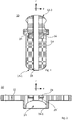
- FIG. 12 shows an additional spring designated overall by the reference number 10.
- the auxiliary spring 10 comprises a first spring body 12, a second spring body 14 and a stop buffer 16.
- the two spring bodies 12, 14 are arranged in series, viewed in the axial direction a, and the first spring body 12 is spherical on its end face 12-1 facing away from the second spring body 14 formed, ie the surface has a hemispherical configuration.
- the second spring body 14 is also spherical, here again hemispherical, on its end face 14-1 facing away from the first spring body 12, via which the second spring body 14 is supported on the shock absorber cap 34 during compression, cf. 3 .
- the stop buffer 16 viewed in the axial direction a is arranged between the first and second spring body 12, 14, presently in a cavity formed in the second spring body 14.
- the stop buffer 16 can optionally be provided with a piezoelectric pressure sensor 28, which supplies corresponding input signals for a chassis control.
- the spring bodies 12, 14 and the stop buffer 16 are each provided with a central bore 18 arranged in alignment with one another.
- the spring bodies 12, 14 and the stop buffer 16 have different spring stiffnesses.
- Made of an elostomeric material such. B. polyurethane, trained spring body 12, 14 are designed so that the first spring body 12 has a comparison to the second spring body 14 higher spring stiffness.
- the stop buffer 16 made of a plastic material, preferably polyamide, has a significantly higher spring stiffness compared to the first spring element 12 .
- FIG. 12 shows, in a schematic representation, a damper mount designated overall by the reference number 20 .
- the top mount 20 includes a flange area 22 for attachment to a vehicle body and a cylindrical receiving space 24 designed as a hollow body for partially accommodating the first spring body 12 of the auxiliary spring 10.
- the top mount 20 also includes an elastomeric bearing element 26 in the flange area 22 for screwing the piston rod 32 of the Shock absorber 30.
- the damper bearing 20 can be provided with a piezoelectric pressure sensor 28′, which supplies corresponding input signals to a chassis controller.
- the arrangement of the piezoelectric pressure sensor 28' in the damper bearing 20 proves to be particularly advantageous, since this enables simplified laying of the electrical lines for the chassis control.
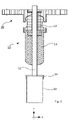
- FIG 3 shows a schematic representation of the auxiliary spring 10 and the damper bearing 20 in the mounted state on a piston rod 32 of a shock absorber 30. Due to the inventive design of the contact surfaces 12-1 of the first spring body 12 and the bottom surface 24-1 of the damper bearing 24 lies between the auxiliary spring 10 and The shock absorber mount features a type of articulated mounting that adjusts the angle when deflecting at an angle, thus enabling offset-free deflection.
Landscapes
- Engineering & Computer Science (AREA)
- Mechanical Engineering (AREA)
- General Engineering & Computer Science (AREA)
- Vehicle Body Suspensions (AREA)
- Fluid-Damping Devices (AREA)
- Springs (AREA)
- Vibration Prevention Devices (AREA)
Description
- Die Erfindung betrifft eine Zusatzfeder für einen Stoßdämpfer eines Kraftfahrzeugs gemäß der im Oberbegriff des Patentanspruches 1 angegebenen Art sowie ein Dämpferlager für einen Stoßdämpfer eines Kraftfahrzeugs gemäß der im Oberbegriff des Patentanspruches 8 angegebenen Art.
- Derartige Zusatzfedern sind aus dem Stand der Technik hinreichend bekannt und werden dazu verwendet, die Gesamtfederungseigenschaften des Fahrzeuges zu definieren und einen gedämpften Endanschlag für eine Radaufhängung auszubilden. Dazu wird die Zusatzfeder auf einer Kolbenstange eines Stoßdämpfers angeordnet, wobei die Zusatzfeder im Bereich eines Dämpferlagers gehalten ist. Federt das Kraftfahrzeug sehr stark ein, so wird die Zusatzfeder zwischen der Dämpferkappe auf dem Dämpferrohr des Stoßdämpfers und dem Dämpferlager komprimiert. Es ist weiterhin bekannt einen progressiven Kennlinienverlauf für die Zusatzfeder vorzusehen, um ein weiches Einfedern und eine progressive Verhärtung der Zusatzfeder bei weiter steigender Kompression zu gewährleisten.
- Eine entsprechende Zusatzfeder und Dämpferlager sind in der
DE 10 2012 020 569 A1 offenbart. - Ein bekanntes Problem von Zusatzfedern ist, dass diese im Bereich der Anbindung an das Dämpferlager einem verstärkten Abrieb und damit Verschleiß unterliegen, was auf die - aufgrund der bei heutigen Kraftfahrzeugen gängige schräg gestellte Anordnung der Stoßdämpfer - Schrägeinfederung, d. h. die nicht-parallele Einfederung der Kolbenstange des Stoßdämpfers zur Kraftfahrzeugkarosserie, zurückzuführen ist.
- Eine gattungsgemäße, sämtliche Merkmale des Oberbegriffs des Patentanspruchs 1 aufweisende Zusatzfeder ist in der
DE 10 2012 018883 A1 offenbart. - Der Erfindung liegt die Aufgabe zu Grunde, eine Zusatzfeder gemäß der im Oberbegriff des Patentanspruches 1 angegebenen Art derart weiterzubilden, dass eine längere Lebensdauer der Zusatzfeder gewährleistet ist.
- Diese Aufgabe wird durch die kennzeichnenden Merkmale des Patentanspruches 1 in Verbindung mit seinen Oberbegriffsmerkmalen gelöst.
- Die Unteransprüche 2 bis 7 stellen vorteilhafte Weiterbildungen der Erfindung vor.
- In bekannter Art und Weise umfasst die Zusatzfeder einen ersten Federkörper, der eine zentrale Bohrung für die Durchführung einer Kolbenstange des Stoßdämpfers aufweist.
- Dabei ist der erste Federkörper an einer Stirnseite sphärisch ausgebildet. Diese Ausgestaltung hat den Effekt, dass nach bestimmungsgemäßer Montage der Zusatzfeder auf die Kolbenstange des Stoßdämpfers (=> bestimmungsgemäße Montage heißt, dass nach Montage die sphärische Stirnseite des Federkörpers zum karosserieseitigen Dämpferlager ausgerichtet ist), aufgrund der sphärischen Stirnseite des ersten Federkörpers nunmehr zwischen dem Dämpferlager und dem Federkörper eine "gelenkige" Lagerung ermöglicht ist, durch die die Nachteile der Schrägeinfederung kompensiert werden. Hierdurch ist ein versatzfreies Einfedern sichergestellt, mit der Konsequenz, dass der nachteilige Abrieb am Federkörper nicht mehr bzw. nur noch im geringeren Maße auftritt, so dass ein verschleißfreierer Betrieb und damit eine längere Lebensdauer des ersten Federkörpers und damit der Zusatzfeder gewährleistet ist.
- Die Zusatzfeder umfasst ferner einen zweiten Federkörper, der eine in Bezug zum ersten Federkörper andere, vorteilhaft geringere Federsteifigkeit aufweist und der mit einer zentralen Bohrung für die Durchführung einer Kolbenstange des Stoßdämpfers versehen ist, wobei der erste Federkörper gegenüberliegend zur sphärischen Stirnseite angrenzend zum ersten Federkörper und damit in Reihe zum ersten Federkörper angeordnet ist.
- Hierdurch ist eine verbesserte Feinabstimmung des gewünschten progressiven Kennlinienverlaufs der Federkraft der Zusatzfeder ermöglicht. So ist durch eine entsprechende Auswahl der Federsteifigkeiten der beiden Federkörper, nämlich harte Federsteifigkeit für den ersten Federkörper und im Vergleich dazu sehr weiche Federrate für den zweiten Federkörper, eine sehr weiche Anfederrate bei unbeladenem Fahrzeug und Komfortanfedern mit leichter Progression, ermöglicht. Zudem weist eine derart ausgebildete Zusatzfeder eine längere Lebensdauer auf. Dies ist darauf zurückzuführen, dass in einem Verschleißfall in der Regel nur der zweite Federkörper betroffen ist, da dieser aufgrund seiner geringeren Federsteifigkeit verschleißanfälliger ist, und somit nur dieser und nicht die gesamte Zusatzfeder auszutauschen ist. Aufgrund des modularen Aufbaus der Zusatzfeder ist zudem ein für unterschiedliche Fahrzeuge einsetzbares Baukastensystem zur Verfügung gestellt, was eine Reduzierung der Variantenvielfalt der Zusatzfedern und damit eine Kostenreduktion zur Folge hat.
- Die Zusatzfeder umfasst ferner einen zwischen dem ersten und dem zweiten Federkörper angeordneten Anschlagpuffer, der entsprechend zu dem ersten und zweiten Federkörper eine zentrale Bohrung für die Durchführung der Kolbenstange des Stoßdämpfers aufweist und der in Bezug zu den beiden Federkörpern eine wesentlich höhere Federsteifigkeit aufweist.
- Aufgrund des eine wesentlich höhere Federsteifigkeit aufweisenden Anschlagpuffers ist eine sehr starke Progression der Zusatzfeder und damit eine Blockbegrenzung z. B. bei einer zu schnellen Bordsteinüberfahrt, gewährleistet.
- Erfindungsgemäß ist nunmehr vorgesehen, dass der zweite Federkörper an seiner dem ersten Federkörper abgewandten Stirnseite ebenfalls sphärisch ausgebildet ist.
- Vorteilhaft an erfindungsgemäßen Ausgestaltung ist, dass aufgrund der sphärischen Ausbildung der Stirnseite des zweiten Federkörpers eine verbesserte Winkelanpassung und damit ein versatzfreies Einfedern ermöglicht ist.
- Vorzugsweise ist dabei die sphärisch ausgebildete Stirnseite des ersten Federkörpers und/oder des zweiten Federkörpers in Form eines Kugelkopfes ausgebildet.
- Vorzugsweise ist dabei der Anschlagpuffer in einem im ersten und/oder zweiten Federkörper ausgebildeten Hohlraum angeordnet.
- Eine weitere besonders vorteilhafte Ausführungsform der Erfindung sieht vor, dass im Anschlagpuffer ein piezoelektrischer Drucksensor integriert ist. Vorteilhaft an dieser Ausführungsform ist, dass mittels des Sensors ein Signalinput für ein Steuergerät zur Fahrwerkssteuerung zur Verfügung gestellt ist.
- Vorzugsweise sind der erste und zweite Federkörper aus einem elastomeren Material, insbesondere aus Polyurethan und der Anschlagpuffer aus Polyamid ausgebildet.
- Der Erfindung liegt des Weiteren die Aufgabe zu Grunde ein Dämpferlager für einen Stoßdämpfer eines Kraftfahrzeugs gemäß der im Oberbegriff des Patentanspruches 8 angegebenen Art derart weiterzubilden, dass sich das Dämpferlager unterstützend auf die angestrebte längere Lebensdauer einer nach den Patentansprüchen 1 bis 7 ausgebildeten Zusatzfeder auswirkt.
- Diese Aufgabe wird durch die kennzeichnenden Merkmale des Patentanspruches 8 in Verbindung mit seinen Oberbegriffsmerkmalen gelöst.
- Die Unteransprüche 9 bis 11 bilden eine vorteilhafte Weiterbildung des erfindungsgemäßen Dämpferlagers.
- In bekannter Art und Weise weist das Dämpferlager für einen Stoßdämpfer eines Kraftfahrzeugs einen Flanschbereich zur Befestigung des Lagers an der Fahrzeugkarosserie sowie einen zylinderförmigen, als Hohlkörper ausgebildeten Aufnahmeraum auf, in dem im montierten Zustand der erste Federkörper der Zusatzfeder bereichsweise gehalten ist.
- Erfindungsgemäß weist nunmehr der Aufnahmeraum eine korrespondierend zur Stirnseite des ersten Federelements ausgebildete, sphärisch geformte Bodenfläche auf. Die erfindungsgemäße Ausgestaltung hat den positiven Effekt, dass nunmehr aufgrund der gegenüber liegenden sphärischen Oberflächen eine optimale Winkelanpassung zwischen erstem Federelement und Dämpferlager ermöglicht ist, und somit der schädliche Effekt der Schrägeinfederung nochmals deutlich reduziert wird.
- Vorzugsweise ist im Flanschbereich ein elastomeres Lagerungselement zur Verschraubung der Kolbenstange des Stoßdämpfers angeordnet.
- Eine weitere vorteilhafte Ausführungsform sieht vor, dass das Lagerungselement einen piezoelektrischen Drucksensor umfasst, der entsprechende Eingangssignale für ein Steuergerät zur Fahrwerkssteuerung liefert. Durch die Anordnung des piezoelektrischen Drucksensors im Lagerungselement und damit im Dämpferlager ist in vorteilhafter Weise eine vereinfachte Verlegung der elektrischen Leitungen zum karosserieseitig angeordneten Steuergerät zur Fahrwerkssteuerung ermöglicht.
- Vorzugsweise ist dabei die Bodenfläche des Aufnahmeraums in Form einer Kugelpfanne ausgebildet.
- Weitere Vorteile und Anwendungsmöglichkeiten der vorliegenden Erfindung ergeben sich aus der nachfolgenden Beschreibung in Verbindung mit dem in der Zeichnung dargestellten Ausführungsbeispiel.
- In der Zeichnung bedeutet:
- Fig. 1
- eine schematische Schnittdarstellung der erfindungsgemäßen Zusatzfeder;
- Fig. 2
- eine schematische Schnittdarstellung des erfindungsgemäßen Dämpferlagers und
- Fig. 3
- die Zusatzfeder aus
Fig. 1 und das Dämpferlager ausFig. 2 im montierten Zustand in einer schematischen Schnittdarstellung. -
Fig. 1 zeigt eine insgesamt mit der Bezugsziffer 10 bezeichnete Zusatzfeder. Die Zusatzfeder 10 umfasst einen ersten Federkörper 12, einen zweiten Federkörper 14 und einen Anschlagpuffer 16. - Dabei sind, wie
Fig. 1 zeigt, die beiden Federkörper 12, 14 in axialer Richtung a betrachtet in Reihe angeordnet und der erste Federkörper 12 ist an seiner dem zweiten Federkörper 14 abgewandten Stirnseite 12-1 sphärisch ausgebildet, d. h. die Oberfläche weist eine halbkugelförmige Ausgestaltung auf. Entsprechend ist auch der zweite Federkörper 14 an seiner dem ersten Federkörper 12 abgewandten Stirnseite 14-1 sphärisch, vorliegend wieder halbkugelförmig, ausgebildet, über die sich der zweite Federkörper 14 beim Einfedern an der Stoßdämpferkappe 34 abstützt, vgl.Fig. 3 . - Wie
Fig. 1 weiter zu entnehmen ist, ist der Anschlagpuffer 16 in axialer Richtung a betrachtet zwischen dem ersten und zweiten Federkörper 12, 14 angeordnet, vorliegend in einem im zweiten Federkörper 14 ausgebildeten Hohlraum. Der Anschlagpuffer 16 kann optional mit einem piezoelektrischen Drucksensor 28 versehen sein, der entsprechende Eingangssignale für eine Fahrwerkssteuerung liefert. - Zudem sind die Federkörper 12, 14 und der Anschlagpuffer 16 jeweils mit einer, fluchtend zueinander angeordneten, zentralen Bohrung 18 versehen.
- Weiterhin weisen die Federkörper 12, 14 sowie der Anschlagpuffer 16 unterschiedliche Federsteifigkeiten auf. Die aus einem elostomeren Material, wie z. B. Polyurethan, ausgebildeten Federkörper 12, 14 sind so ausgelegt, dass der erste Federkörper 12 eine im Vergleich zum zweiten Federkörper 14 höhere Federsteifigkeit aufweist. Und der aus einem Kunststoffmaterial, vorzugsweise Polyamid ausgebildete Anschlagpuffer 16 weist eine im Vergleich zum ersten Federelement 12 nochmals wesentlich höhere Federsteifigkeit auf.
-
Fig. 2 zeigt in einer schematischen Darstellung ein insgesamt mit der Bezugsziffer 20 bezeichnetes Dämpferlager. Das Dämpferlager 20 umfasst einen Flanschbereich 22 zur Befestigung an einer Fahrzeugkarosserie und einen zylinderförmigen, als Hohlkörper ausgebildeten Aufnahmeraum 24 zur teilweisen Aufnahme des ersten Federkörpers 12 der Zusatzfeder 10. Zudem umfasst das Dämpferlager 20 im Flanschbereich 22 ein elastomeres Lagerelement 26 zur Verschraubung der Kolbenstange 32 des Stoßdämpfers 30. Optional kann das Dämpferlager 20 mit einem piezoelektrischen Drucksensor 28'versehen sein, der entsprechende Eingangssignale an eine Fahrwerksteuerung liefert. Die Anordnung des piezoelektrischen Drucksensors 28' im Dämpferlager 20 erweist sich als besonders vorteilhaft, da hierdurch eine vereinfachte Verlegung der elektrischen Leitungen zur Fahrwerkssteuerung ermöglicht ist. - Dabei ist, wie
Fig. 2 zeigt - die Bodenfläche 24-1 des Aufnahmeraums 24 korrespondierend zur sphärisch ausgebildeten Stirnfläche 12-1 des ersten Federkörpers 12 ausgebildet. D. h. die Bodenfläche 24-1 weist eine in Bezug auf die konvexe Formgebung der Stirnfläche 12-1 korrespondierend konkav ausgebildete Gegenkontur auf. -
Fig. 3 zeigt in einer schematischen Darstellung die Zusatzfeder 10 und das Dämpferlager 20 im montierten Zustand auf einer Kolbenstange 32 eines Stoßdämpfers 30. Aufgrund der erfindungsgemäßen Ausgestaltung der Kontaktflächen 12-1 des ersten Federkörpers 12 und der Bodenfläche 24-1 des Dämpferlagers 24 liegt zwischen Zusatzfeder 10 und Dämpferlager eine Art gelenkige Lagerung vor, die beim Schrägeinfedern eine Winkelanpassung bewirkt und damit ein versatzfreies Einfedern ermöglicht.
Claims (11)
- Zusatzfeder (10) für einen Stoßdämpfer eines Kraftfahrzeugs, umfassend einen ersten Federkörper (12) und einen zweiten Federkörper (14) mit einer in Bezug zum ersten Federkörper (12) unterschiedlichen Federsteifigkeit, wobei die Federkörper (12, 14) jeweils eine zentrale Bohrung (18) für die Durchführung einer Kolbenstange (32) des Stoßdämpfers (30) aufweisen, wobei zwischen dem ersten und zweiten Federkörper (12, 14) ein Anschlagpuffer (16) angeordnet ist, der eine in Bezug zu den beiden Federkörpern (12, 16) höhere Federsteifigkeit aufweist und der eine zentrale Bohrung (18) für die Durchführung einer Kolbenstange (32) des Stoßdämpfers (30) aufweist,
wobei der zweite Federkörper (14) an seiner dem ersten Federkörper (12) abgewandten Stirnseite (14-1) sphärisch ausgebildet ist,
dadurch gekennzeichnet, dass der erste Federkörper (12) an einer Stirnseite (12-1) sphärisch ausgebildet ist, und wobei der zweite Federkörper (14) gegenüberliegend zur sphärischen Stirnseite (12-1), angrenzend zum ersten Federkörper (12) angeordnet ist. - Zusatzfeder (10) nach Anspruch 1,
dadurch gekennzeichnet, dass
die sphärische ausgebildete Stirnseite (12-1, 14-1) in Form eines Kugelkopfes ausgebildet ist. - Zusatzfeder (10) nach Anspruch 1,
dadurch gekennzeichnet, dass
der Anschlagpuffer (16) in einem im ersten und/oder zweiten Federkörper (12, 14) ausgebildeten Hohlraum angeordnet ist. - Zusatzfeder (10) nach einem der Ansprüche 1,
dadurch gekennzeichnet, dass
im Anschlagpuffer (16) ein piezoelektrischer Drucksensor (28) integriert ist. - Zusatzfeder (10) nach einem der vorgenannten Ansprüche,
dadurch gekennzeichnet, dass
der Anschlagpuffer (16) aus Polyamid ausgebildet ist. - Zusatzfeder nach einem der vorgenannten Ansprüche,
dadurch gekennzeichnet, dass
der erste und/oder zweite Federkörper (12, 14) aus einem elastomeren Material ausgebildet sind. - Zusatzfeder nach Anspruch 6,
dadurch gekennzeichnet, dass
der erste und/oder zweite Federkörper (12, 14) aus Polyurethan ausgebildet sind. - Dämpferlager (20) für einen Stoßdämpfers eines Kraftfahrzeugs, mit einer Zusatzfeder (10) gemäß einem der Ansprüche 1 bis 7, umfassend einen Flanschbereich (22) zur Befestigung an einer Fahrzeugkarosserie sowie einen zylinderförmigen Aufnahmeraum (24), in dem im montierten Zustand der erste Federkörper (12) der Zusatzfeder (10) bereichsweise gehalten ist,
dadurch gekennzeichnet, dass
der Aufnahmeraum (24) eine korrespondierend zur Stirnseite (12-1) des ersten Federkörpers (12) ausgebildete, sphärisch geformte Bodenfläche (24-1) aufweist. - Dämpferlager (20) nach Anspruch 8,
dadurch gekennzeichnet, dass
im Flanschbereich (22) ein elastomeres Lagerungselement (26) angeordnet ist. - Dämpferlager (20) nach Anspruch 9,
dadurch gekennzeichnet, dass
das elastomere Lagerungselement (26) einen piezoelektrischen Drucksensor (28') umfasst. - Dämpferlager (20) nach einem der Ansprüche 8 bis 10,
dadurch gekennzeichnet, dass
die Bodenfläche (24-1) des Aufnahmeraums (24) in Form einer Kugelpfanne ausgebildet ist.
Applications Claiming Priority (2)
| Application Number | Priority Date | Filing Date | Title |
|---|---|---|---|
| DE102017221975.0A DE102017221975A1 (de) | 2017-12-06 | 2017-12-06 | Zusatzfeder für einen Stoßdämpfer eines Kraftfahrzeugs und Dämpferlager für einen Stoßdämpfer eines Kraftfahrzeugs |
| PCT/EP2018/082294 WO2019110320A1 (de) | 2017-12-06 | 2018-11-22 | ZUSATZFEDER FÜR EINEN STOßDÄMPFER EINES KRAFTFAHRZEUGS UND DÄMPFERLAGER FÜR EINEN STOßDÄMPFER EINES KRAFTFAHRZEUGS |
Publications (2)
| Publication Number | Publication Date |
|---|---|
| EP3720725A1 EP3720725A1 (de) | 2020-10-14 |
| EP3720725B1 true EP3720725B1 (de) | 2022-11-09 |
Family
ID=64606942
Family Applications (1)
| Application Number | Title | Priority Date | Filing Date |
|---|---|---|---|
| EP18814798.7A Active EP3720725B1 (de) | 2017-12-06 | 2018-11-22 | Zusatzfeder für einen stossdämpfer eines kraftfahrzeugs und dämpferlager für einen stossdämpfer eines kraftfahrzeugs |
Country Status (5)
| Country | Link |
|---|---|
| US (1) | US20200307335A1 (de) |
| EP (1) | EP3720725B1 (de) |
| CN (1) | CN111433058B (de) |
| DE (1) | DE102017221975A1 (de) |
| WO (1) | WO2019110320A1 (de) |
Families Citing this family (2)
| Publication number | Priority date | Publication date | Assignee | Title |
|---|---|---|---|---|
| DE102019218648B4 (de) * | 2019-11-29 | 2021-06-10 | Volkswagen Aktiengesellschaft | Fahrzeug mit einer Zusatzfeder |
| CN112013075B (zh) * | 2020-08-25 | 2025-04-01 | 常州工学院 | 一种快速回位减振器 |
Citations (1)
| Publication number | Priority date | Publication date | Assignee | Title |
|---|---|---|---|---|
| US20060043659A1 (en) * | 2004-08-30 | 2006-03-02 | Marian Gofron | Dual spring jounce bumper assembly |
Family Cites Families (31)
| Publication number | Priority date | Publication date | Assignee | Title |
|---|---|---|---|---|
| DE8413300U1 (de) * | 1984-09-20 | Gold, Henning, Prof.Dr.Ing., 6530 Bingen | Pneumatische Feder-Dämpfer-Einheit | |
| US2683007A (en) * | 1949-07-30 | 1954-07-06 | Gen Tire & Rubber Co | Cushioning and vibration dampening support |
| IT1027247B (it) * | 1974-01-04 | 1978-11-20 | Pneumatiques Caoutchouc Mfg | Dispositivo elastico formante molla ed ammortizzatore, parti colarmente per sospensioni di veicoli |
| GB2079400A (en) * | 1980-07-04 | 1982-01-20 | Norde Suspensions Ltd | Suspension or damping unit |
| ES274989Y (es) * | 1981-02-03 | 1985-01-16 | Neil Paton H. | Biela de suspension perfeccionada. |
| JP2548907Y2 (ja) * | 1991-02-21 | 1997-09-24 | 株式会社ユニシアジェックス | 荷重センサの取付構造 |
| JP3161144B2 (ja) * | 1992-05-20 | 2001-04-25 | 株式会社デンソー | 減衰力可変ショックアブソーバ制御装置 |
| FR2696269A1 (fr) * | 1992-09-28 | 1994-04-01 | Bellec Jean Yves | Dispositif d'atténuation des vibrations sonores. |
| DE19715255C2 (de) * | 1997-04-12 | 1999-06-02 | Eppendorf Geraetebau Netheler | Dämpfender Gerätefuß |
| DE10026970B4 (de) * | 2000-05-31 | 2016-03-10 | Volkswagen Ag | Elastomerfeder und Stoßdämpferanordnung mit einer solchen Elastomerfeder |
| DE10105791A1 (de) * | 2001-02-07 | 2002-08-08 | Basf Ag | Federelement |
| KR100456014B1 (ko) * | 2001-05-02 | 2004-11-08 | 주식회사 만도 | 쇽 업소버의 범퍼 스토퍼 |
| DE10124924B4 (de) * | 2001-05-21 | 2021-08-26 | Basf Se | Federelement und Automobil enthaltend das Federelement |
| FR2860851B1 (fr) * | 2003-10-10 | 2006-03-10 | Peugeot Citroen Automobiles Sa | Butee de compresion, notamment pour amortisseur de suspension de vehicule automobile |
| US7338040B2 (en) * | 2005-06-14 | 2008-03-04 | Freudenberg-Nok General Partnership | High retention strength jounce bumper assembly |
| DE102005037477A1 (de) * | 2005-08-09 | 2007-02-22 | Zf Friedrichshafen Ag | Schwingungsdämpfer |
| DE102008033820B4 (de) * | 2008-07-19 | 2015-06-25 | Audi Ag | Kraftfahrzeug mit aktiver Federung |
| EP2255980B1 (de) * | 2009-05-27 | 2012-08-08 | Ford Global Technologies, LLC | Radaufhängung |
| DE102010007237A1 (de) * | 2010-02-09 | 2010-09-23 | Daimler Ag | Federungssystem für ein Fahrzeug |
| US20110291338A1 (en) * | 2010-05-27 | 2011-12-01 | Pepka Charles F | Preloaded dual-spring assembly |
| US8356807B2 (en) * | 2010-06-24 | 2013-01-22 | Miner Elastomer Products Corporation | Dual rate shock absorbing apparatus for a suspension system of a heavy off-road vehicle |
| FR2983954B1 (fr) * | 2011-12-13 | 2014-09-12 | Renault Sa | Ressort avec capteur de deformation integre. |
| DE102013217343B4 (de) * | 2012-08-31 | 2022-10-20 | Firestone Industrial Products Company, Llc | Anschlagpuffer und diese umfassende federanordnungen |
| DE102012018883B4 (de) * | 2012-09-25 | 2017-06-08 | Audi Ag | Zusatzfeder |
| DE102012020569B4 (de) | 2012-10-19 | 2014-10-30 | Audi Ag | Zusatzfeder, Dämpferlager und Stoßdämpfer |
| KR101551061B1 (ko) * | 2014-02-17 | 2015-09-07 | 현대자동차주식회사 | 더스트 커버 일체형 범퍼스토퍼 |
| DE102015200383B4 (de) * | 2015-01-14 | 2016-11-03 | Ford Global Technologies, Llc | Dämpfereinheit für ein Federungssystem mit einem semiaktiven Dämpfungsmittel |
| CN107206860B (zh) * | 2015-02-06 | 2020-03-10 | 伯恩斯公司 | 车辆底盘水平传感器 |
| DE102016201733A1 (de) * | 2016-02-04 | 2017-08-10 | Ford Global Technologies, Llc | Stoßdämpfer-Baugruppe für ein Kraftfahrzeug |
| US10221913B2 (en) * | 2016-06-21 | 2019-03-05 | Beijingwest Industries Co., Ltd. | Hydraulic damper with a piston rod protective tube |
| KR102750673B1 (ko) * | 2020-03-23 | 2025-01-06 | 현대자동차주식회사 | 차량 현가장치용 인슐레이터 및 그 제조 방법 |
-
2017
- 2017-12-06 DE DE102017221975.0A patent/DE102017221975A1/de not_active Withdrawn
-
2018
- 2018-11-22 EP EP18814798.7A patent/EP3720725B1/de active Active
- 2018-11-22 CN CN201880078575.1A patent/CN111433058B/zh active Active
- 2018-11-22 US US16/769,356 patent/US20200307335A1/en not_active Abandoned
- 2018-11-22 WO PCT/EP2018/082294 patent/WO2019110320A1/de not_active Ceased
Patent Citations (1)
| Publication number | Priority date | Publication date | Assignee | Title |
|---|---|---|---|---|
| US20060043659A1 (en) * | 2004-08-30 | 2006-03-02 | Marian Gofron | Dual spring jounce bumper assembly |
Also Published As
| Publication number | Publication date |
|---|---|
| US20200307335A1 (en) | 2020-10-01 |
| EP3720725A1 (de) | 2020-10-14 |
| CN111433058B (zh) | 2023-05-16 |
| DE102017221975A1 (de) | 2019-06-06 |
| WO2019110320A1 (de) | 2019-06-13 |
| CN111433058A (zh) | 2020-07-17 |
Similar Documents
| Publication | Publication Date | Title |
|---|---|---|
| DE102011053193B4 (de) | Struktur eines aufhängungshalters für ein fahrzeug | |
| DE102015007743B4 (de) | Schublager und druckluftbeaufschlagter Stoßdämpfer | |
| DE202009019095U1 (de) | Passive Stabilisatorvorrichtung für eine Kraftfahrzeugradaufhängung und Radaufhängung | |
| DE102013210046B4 (de) | Trägerbaugruppe für einen Federungsdämpfer | |
| DE102012012902A1 (de) | Luftfedermodul | |
| DE102008007107A1 (de) | Axialkugelgelenk mit Anschlagdämpfung | |
| DE102009047404A1 (de) | Radaufhängung | |
| EP3720725B1 (de) | Zusatzfeder für einen stossdämpfer eines kraftfahrzeugs und dämpferlager für einen stossdämpfer eines kraftfahrzeugs | |
| DE102015207316A1 (de) | System zum Einstellen der Federhärte einer Fahrwerksfeder | |
| EP0747245B1 (de) | Stützlager für einen Stossdämpfer eines Kraftfahrzeuges | |
| DE102010055141A1 (de) | Federunterlage für eine freistehende Tragfeder eines Kraftfahrzeugs | |
| EP3338005B1 (de) | Luftfeder und ihre verwendung | |
| DE10330877B4 (de) | Fahrwerkslager | |
| DE102017213935A1 (de) | Entkopplungseinheit und Wankstabilisator mit einer solchen Entkopplungseinheit | |
| DE9218307U1 (de) | Zentralgelenk eines Dreiecklenkers in einem Kraftfahrzeug | |
| EP1426211A2 (de) | Aus Feder und Dämpfer bestehende Federungsanordnung | |
| DE102019212696A1 (de) | Achsaufhängung für ein Fahrzeug | |
| DE102013107676A1 (de) | Hebel für einen Stabilisator für ein Kraftfahrzeug und Kraftfahrzeug | |
| DE102019212926B4 (de) | Anschlagdämpfer | |
| DE102017215403A1 (de) | Federbaugruppe | |
| DE102011008618A1 (de) | Feder-Dämpfersystem, insbesondere für eine Radaufhängung von Kraftfahrzeugen | |
| DE19507397C2 (de) | Verbundlenker- oder Koppellenkerachse für Kraftfahrzeuge | |
| DE102019210996B3 (de) | Federvorrichtung, Dämpfungsvorrichtung und Kraftfahrzeug | |
| DE102014017979B4 (de) | Schwingungsdämpfer für ein Kraftfahrzeug | |
| DE102011079163B4 (de) | Lagereinheit für Nutzfahrzeuge |
Legal Events
| Date | Code | Title | Description |
|---|---|---|---|
| STAA | Information on the status of an ep patent application or granted ep patent |
Free format text: STATUS: UNKNOWN |
|
| STAA | Information on the status of an ep patent application or granted ep patent |
Free format text: STATUS: THE INTERNATIONAL PUBLICATION HAS BEEN MADE |
|
| PUAI | Public reference made under article 153(3) epc to a published international application that has entered the european phase |
Free format text: ORIGINAL CODE: 0009012 |
|
| STAA | Information on the status of an ep patent application or granted ep patent |
Free format text: STATUS: REQUEST FOR EXAMINATION WAS MADE |
|
| 17P | Request for examination filed |
Effective date: 20200706 |
|
| AK | Designated contracting states |
Kind code of ref document: A1 Designated state(s): AL AT BE BG CH CY CZ DE DK EE ES FI FR GB GR HR HU IE IS IT LI LT LU LV MC MK MT NL NO PL PT RO RS SE SI SK SM TR |
|
| AX | Request for extension of the european patent |
Extension state: BA ME |
|
| DAV | Request for validation of the european patent (deleted) | ||
| DAX | Request for extension of the european patent (deleted) | ||
| STAA | Information on the status of an ep patent application or granted ep patent |
Free format text: STATUS: EXAMINATION IS IN PROGRESS |
|
| 17Q | First examination report despatched |
Effective date: 20210622 |
|
| GRAP | Despatch of communication of intention to grant a patent |
Free format text: ORIGINAL CODE: EPIDOSNIGR1 |
|
| STAA | Information on the status of an ep patent application or granted ep patent |
Free format text: STATUS: GRANT OF PATENT IS INTENDED |
|
| INTG | Intention to grant announced |
Effective date: 20220831 |
|
| GRAS | Grant fee paid |
Free format text: ORIGINAL CODE: EPIDOSNIGR3 |
|
| GRAA | (expected) grant |
Free format text: ORIGINAL CODE: 0009210 |
|
| STAA | Information on the status of an ep patent application or granted ep patent |
Free format text: STATUS: THE PATENT HAS BEEN GRANTED |
|
| AK | Designated contracting states |
Kind code of ref document: B1 Designated state(s): AL AT BE BG CH CY CZ DE DK EE ES FI FR GB GR HR HU IE IS IT LI LT LU LV MC MK MT NL NO PL PT RO RS SE SI SK SM TR |
|
| REG | Reference to a national code |
Ref country code: GB Ref legal event code: FG4D Free format text: NOT ENGLISH |
|
| REG | Reference to a national code |
Ref country code: CH Ref legal event code: EP Ref country code: AT Ref legal event code: REF Ref document number: 1530124 Country of ref document: AT Kind code of ref document: T Effective date: 20221115 |
|
| REG | Reference to a national code |
Ref country code: DE Ref legal event code: R096 Ref document number: 502018011024 Country of ref document: DE |
|
| REG | Reference to a national code |
Ref country code: IE Ref legal event code: FG4D Free format text: LANGUAGE OF EP DOCUMENT: GERMAN |
|
| REG | Reference to a national code |
Ref country code: LT Ref legal event code: MG9D |
|
| REG | Reference to a national code |
Ref country code: NL Ref legal event code: MP Effective date: 20221109 |
|
| PG25 | Lapsed in a contracting state [announced via postgrant information from national office to epo] |
Ref country code: SE Free format text: LAPSE BECAUSE OF FAILURE TO SUBMIT A TRANSLATION OF THE DESCRIPTION OR TO PAY THE FEE WITHIN THE PRESCRIBED TIME-LIMIT Effective date: 20221109 Ref country code: PT Free format text: LAPSE BECAUSE OF FAILURE TO SUBMIT A TRANSLATION OF THE DESCRIPTION OR TO PAY THE FEE WITHIN THE PRESCRIBED TIME-LIMIT Effective date: 20230309 Ref country code: NO Free format text: LAPSE BECAUSE OF FAILURE TO SUBMIT A TRANSLATION OF THE DESCRIPTION OR TO PAY THE FEE WITHIN THE PRESCRIBED TIME-LIMIT Effective date: 20230209 Ref country code: LT Free format text: LAPSE BECAUSE OF FAILURE TO SUBMIT A TRANSLATION OF THE DESCRIPTION OR TO PAY THE FEE WITHIN THE PRESCRIBED TIME-LIMIT Effective date: 20221109 Ref country code: FI Free format text: LAPSE BECAUSE OF FAILURE TO SUBMIT A TRANSLATION OF THE DESCRIPTION OR TO PAY THE FEE WITHIN THE PRESCRIBED TIME-LIMIT Effective date: 20221109 Ref country code: ES Free format text: LAPSE BECAUSE OF FAILURE TO SUBMIT A TRANSLATION OF THE DESCRIPTION OR TO PAY THE FEE WITHIN THE PRESCRIBED TIME-LIMIT Effective date: 20221109 |
|
| PG25 | Lapsed in a contracting state [announced via postgrant information from national office to epo] |
Ref country code: RS Free format text: LAPSE BECAUSE OF FAILURE TO SUBMIT A TRANSLATION OF THE DESCRIPTION OR TO PAY THE FEE WITHIN THE PRESCRIBED TIME-LIMIT Effective date: 20221109 Ref country code: PL Free format text: LAPSE BECAUSE OF FAILURE TO SUBMIT A TRANSLATION OF THE DESCRIPTION OR TO PAY THE FEE WITHIN THE PRESCRIBED TIME-LIMIT Effective date: 20221109 Ref country code: LV Free format text: LAPSE BECAUSE OF FAILURE TO SUBMIT A TRANSLATION OF THE DESCRIPTION OR TO PAY THE FEE WITHIN THE PRESCRIBED TIME-LIMIT Effective date: 20221109 Ref country code: IS Free format text: LAPSE BECAUSE OF FAILURE TO SUBMIT A TRANSLATION OF THE DESCRIPTION OR TO PAY THE FEE WITHIN THE PRESCRIBED TIME-LIMIT Effective date: 20230309 Ref country code: HR Free format text: LAPSE BECAUSE OF FAILURE TO SUBMIT A TRANSLATION OF THE DESCRIPTION OR TO PAY THE FEE WITHIN THE PRESCRIBED TIME-LIMIT Effective date: 20221109 Ref country code: GR Free format text: LAPSE BECAUSE OF FAILURE TO SUBMIT A TRANSLATION OF THE DESCRIPTION OR TO PAY THE FEE WITHIN THE PRESCRIBED TIME-LIMIT Effective date: 20230210 |
|
| PG25 | Lapsed in a contracting state [announced via postgrant information from national office to epo] |
Ref country code: NL Free format text: LAPSE BECAUSE OF FAILURE TO SUBMIT A TRANSLATION OF THE DESCRIPTION OR TO PAY THE FEE WITHIN THE PRESCRIBED TIME-LIMIT Effective date: 20221109 |
|
| REG | Reference to a national code |
Ref country code: CH Ref legal event code: PL |
|
| P01 | Opt-out of the competence of the unified patent court (upc) registered |
Effective date: 20230530 |
|
| REG | Reference to a national code |
Ref country code: BE Ref legal event code: MM Effective date: 20221130 |
|
| PG25 | Lapsed in a contracting state [announced via postgrant information from national office to epo] |
Ref country code: SM Free format text: LAPSE BECAUSE OF FAILURE TO SUBMIT A TRANSLATION OF THE DESCRIPTION OR TO PAY THE FEE WITHIN THE PRESCRIBED TIME-LIMIT Effective date: 20221109 Ref country code: RO Free format text: LAPSE BECAUSE OF FAILURE TO SUBMIT A TRANSLATION OF THE DESCRIPTION OR TO PAY THE FEE WITHIN THE PRESCRIBED TIME-LIMIT Effective date: 20221109 Ref country code: LI Free format text: LAPSE BECAUSE OF NON-PAYMENT OF DUE FEES Effective date: 20221130 Ref country code: EE Free format text: LAPSE BECAUSE OF FAILURE TO SUBMIT A TRANSLATION OF THE DESCRIPTION OR TO PAY THE FEE WITHIN THE PRESCRIBED TIME-LIMIT Effective date: 20221109 Ref country code: DK Free format text: LAPSE BECAUSE OF FAILURE TO SUBMIT A TRANSLATION OF THE DESCRIPTION OR TO PAY THE FEE WITHIN THE PRESCRIBED TIME-LIMIT Effective date: 20221109 Ref country code: CZ Free format text: LAPSE BECAUSE OF FAILURE TO SUBMIT A TRANSLATION OF THE DESCRIPTION OR TO PAY THE FEE WITHIN THE PRESCRIBED TIME-LIMIT Effective date: 20221109 Ref country code: CH Free format text: LAPSE BECAUSE OF NON-PAYMENT OF DUE FEES Effective date: 20221130 |
|
| REG | Reference to a national code |
Ref country code: DE Ref legal event code: R097 Ref document number: 502018011024 Country of ref document: DE |
|
| PG25 | Lapsed in a contracting state [announced via postgrant information from national office to epo] |
Ref country code: SK Free format text: LAPSE BECAUSE OF FAILURE TO SUBMIT A TRANSLATION OF THE DESCRIPTION OR TO PAY THE FEE WITHIN THE PRESCRIBED TIME-LIMIT Effective date: 20221109 Ref country code: LU Free format text: LAPSE BECAUSE OF NON-PAYMENT OF DUE FEES Effective date: 20221122 Ref country code: AL Free format text: LAPSE BECAUSE OF FAILURE TO SUBMIT A TRANSLATION OF THE DESCRIPTION OR TO PAY THE FEE WITHIN THE PRESCRIBED TIME-LIMIT Effective date: 20221109 |
|
| PLBE | No opposition filed within time limit |
Free format text: ORIGINAL CODE: 0009261 |
|
| STAA | Information on the status of an ep patent application or granted ep patent |
Free format text: STATUS: NO OPPOSITION FILED WITHIN TIME LIMIT |
|
| 26N | No opposition filed |
Effective date: 20230810 |
|
| PG25 | Lapsed in a contracting state [announced via postgrant information from national office to epo] |
Ref country code: IE Free format text: LAPSE BECAUSE OF NON-PAYMENT OF DUE FEES Effective date: 20221122 |
|
| PG25 | Lapsed in a contracting state [announced via postgrant information from national office to epo] |
Ref country code: SI Free format text: LAPSE BECAUSE OF FAILURE TO SUBMIT A TRANSLATION OF THE DESCRIPTION OR TO PAY THE FEE WITHIN THE PRESCRIBED TIME-LIMIT Effective date: 20221109 Ref country code: BE Free format text: LAPSE BECAUSE OF NON-PAYMENT OF DUE FEES Effective date: 20221130 |
|
| PG25 | Lapsed in a contracting state [announced via postgrant information from national office to epo] |
Ref country code: CY Free format text: LAPSE BECAUSE OF FAILURE TO SUBMIT A TRANSLATION OF THE DESCRIPTION OR TO PAY THE FEE WITHIN THE PRESCRIBED TIME-LIMIT Effective date: 20221109 |
|
| PG25 | Lapsed in a contracting state [announced via postgrant information from national office to epo] |
Ref country code: MK Free format text: LAPSE BECAUSE OF FAILURE TO SUBMIT A TRANSLATION OF THE DESCRIPTION OR TO PAY THE FEE WITHIN THE PRESCRIBED TIME-LIMIT Effective date: 20221109 Ref country code: IT Free format text: LAPSE BECAUSE OF FAILURE TO SUBMIT A TRANSLATION OF THE DESCRIPTION OR TO PAY THE FEE WITHIN THE PRESCRIBED TIME-LIMIT Effective date: 20221109 Ref country code: HU Free format text: LAPSE BECAUSE OF FAILURE TO SUBMIT A TRANSLATION OF THE DESCRIPTION OR TO PAY THE FEE WITHIN THE PRESCRIBED TIME-LIMIT; INVALID AB INITIO Effective date: 20181122 |
|
| PG25 | Lapsed in a contracting state [announced via postgrant information from national office to epo] |
Ref country code: MC Free format text: LAPSE BECAUSE OF FAILURE TO SUBMIT A TRANSLATION OF THE DESCRIPTION OR TO PAY THE FEE WITHIN THE PRESCRIBED TIME-LIMIT Effective date: 20221109 |
|
| PG25 | Lapsed in a contracting state [announced via postgrant information from national office to epo] |
Ref country code: MC Free format text: LAPSE BECAUSE OF FAILURE TO SUBMIT A TRANSLATION OF THE DESCRIPTION OR TO PAY THE FEE WITHIN THE PRESCRIBED TIME-LIMIT Effective date: 20221109 |
|
| PG25 | Lapsed in a contracting state [announced via postgrant information from national office to epo] |
Ref country code: BG Free format text: LAPSE BECAUSE OF FAILURE TO SUBMIT A TRANSLATION OF THE DESCRIPTION OR TO PAY THE FEE WITHIN THE PRESCRIBED TIME-LIMIT Effective date: 20221109 |
|
| PG25 | Lapsed in a contracting state [announced via postgrant information from national office to epo] |
Ref country code: MT Free format text: LAPSE BECAUSE OF FAILURE TO SUBMIT A TRANSLATION OF THE DESCRIPTION OR TO PAY THE FEE WITHIN THE PRESCRIBED TIME-LIMIT Effective date: 20221109 |
|
| REG | Reference to a national code |
Ref country code: AT Ref legal event code: MM01 Ref document number: 1530124 Country of ref document: AT Kind code of ref document: T Effective date: 20231122 |
|
| PG25 | Lapsed in a contracting state [announced via postgrant information from national office to epo] |
Ref country code: AT Free format text: LAPSE BECAUSE OF NON-PAYMENT OF DUE FEES Effective date: 20231122 |
|
| PG25 | Lapsed in a contracting state [announced via postgrant information from national office to epo] |
Ref country code: AT Free format text: LAPSE BECAUSE OF NON-PAYMENT OF DUE FEES Effective date: 20231122 |
|
| PG25 | Lapsed in a contracting state [announced via postgrant information from national office to epo] |
Ref country code: TR Free format text: LAPSE BECAUSE OF FAILURE TO SUBMIT A TRANSLATION OF THE DESCRIPTION OR TO PAY THE FEE WITHIN THE PRESCRIBED TIME-LIMIT Effective date: 20221109 |
|
| PGFP | Annual fee paid to national office [announced via postgrant information from national office to epo] |
Ref country code: DE Payment date: 20251130 Year of fee payment: 8 |
|
| PGFP | Annual fee paid to national office [announced via postgrant information from national office to epo] |
Ref country code: GB Payment date: 20251120 Year of fee payment: 8 |
|
| PGFP | Annual fee paid to national office [announced via postgrant information from national office to epo] |
Ref country code: FR Payment date: 20251120 Year of fee payment: 8 |
|
| PGFP | Annual fee paid to national office [announced via postgrant information from national office to epo] |
Ref country code: AT Payment date: 20260410 Year of fee payment: 5 |