EP3338005B1 - Luftfeder und ihre verwendung - Google Patents
Luftfeder und ihre verwendung Download PDFInfo
- Publication number
- EP3338005B1 EP3338005B1 EP16721801.5A EP16721801A EP3338005B1 EP 3338005 B1 EP3338005 B1 EP 3338005B1 EP 16721801 A EP16721801 A EP 16721801A EP 3338005 B1 EP3338005 B1 EP 3338005B1
- Authority
- EP
- European Patent Office
- Prior art keywords
- air
- connection
- spring
- bayonet closure
- plug
- Prior art date
- Legal status (The legal status is an assumption and is not a legal conclusion. Google has not performed a legal analysis and makes no representation as to the accuracy of the status listed.)
- Active
Links
Images



Classifications
-
- F—MECHANICAL ENGINEERING; LIGHTING; HEATING; WEAPONS; BLASTING
- F16—ENGINEERING ELEMENTS AND UNITS; GENERAL MEASURES FOR PRODUCING AND MAINTAINING EFFECTIVE FUNCTIONING OF MACHINES OR INSTALLATIONS; THERMAL INSULATION IN GENERAL
- F16F—SPRINGS; SHOCK-ABSORBERS; MEANS FOR DAMPING VIBRATION
- F16F9/00—Springs, vibration-dampers, shock-absorbers, or similarly-constructed movement-dampers using a fluid or the equivalent as damping medium
- F16F9/02—Springs, vibration-dampers, shock-absorbers, or similarly-constructed movement-dampers using a fluid or the equivalent as damping medium using gas only or vacuum
- F16F9/04—Springs, vibration-dampers, shock-absorbers, or similarly-constructed movement-dampers using a fluid or the equivalent as damping medium using gas only or vacuum in a chamber with a flexible wall
- F16F9/0454—Springs, vibration-dampers, shock-absorbers, or similarly-constructed movement-dampers using a fluid or the equivalent as damping medium using gas only or vacuum in a chamber with a flexible wall characterised by the assembling method or by the mounting arrangement, e.g. mounting of the membrane
-
- A—HUMAN NECESSITIES
- A01—AGRICULTURE; FORESTRY; ANIMAL HUSBANDRY; HUNTING; TRAPPING; FISHING
- A01B—SOIL WORKING IN AGRICULTURE OR FORESTRY; PARTS, DETAILS, OR ACCESSORIES OF AGRICULTURAL MACHINES OR IMPLEMENTS, IN GENERAL
- A01B63/00—Lifting or adjusting devices or arrangements for agricultural machines or implements
- A01B63/002—Devices for adjusting or regulating the position of tools or wheels
-
- B—PERFORMING OPERATIONS; TRANSPORTING
- B60—VEHICLES IN GENERAL
- B60G—VEHICLE SUSPENSION ARRANGEMENTS
- B60G11/00—Resilient suspensions characterised by arrangement, location or kind of springs
- B60G11/26—Resilient suspensions characterised by arrangement, location or kind of springs having fluid springs only, e.g. hydropneumatic springs
- B60G11/28—Resilient suspensions characterised by arrangement, location or kind of springs having fluid springs only, e.g. hydropneumatic springs characterised by means specially adapted for attaching the spring to axle or sprung part of the vehicle
-
- B—PERFORMING OPERATIONS; TRANSPORTING
- B60—VEHICLES IN GENERAL
- B60N—SEATS SPECIALLY ADAPTED FOR VEHICLES; VEHICLE PASSENGER ACCOMMODATION NOT OTHERWISE PROVIDED FOR
- B60N2/00—Seats specially adapted for vehicles; Arrangement or mounting of seats in vehicles
- B60N2/50—Seat suspension devices
- B60N2/52—Seat suspension devices using fluid means
- B60N2/525—Seat suspension devices using fluid means using gas
-
- B—PERFORMING OPERATIONS; TRANSPORTING
- B62—LAND VEHICLES FOR TRAVELLING OTHERWISE THAN ON RAILS
- B62D—MOTOR VEHICLES; TRAILERS
- B62D33/00—Superstructures for load-carrying vehicles
- B62D33/06—Drivers' cabs
- B62D33/0604—Cabs insulated against vibrations or noise, e.g. with elastic suspension
- B62D33/0608—Cabs insulated against vibrations or noise, e.g. with elastic suspension pneumatic or hydraulic suspension
-
- F—MECHANICAL ENGINEERING; LIGHTING; HEATING; WEAPONS; BLASTING
- F16—ENGINEERING ELEMENTS AND UNITS; GENERAL MEASURES FOR PRODUCING AND MAINTAINING EFFECTIVE FUNCTIONING OF MACHINES OR INSTALLATIONS; THERMAL INSULATION IN GENERAL
- F16F—SPRINGS; SHOCK-ABSORBERS; MEANS FOR DAMPING VIBRATION
- F16F9/00—Springs, vibration-dampers, shock-absorbers, or similarly-constructed movement-dampers using a fluid or the equivalent as damping medium
- F16F9/02—Springs, vibration-dampers, shock-absorbers, or similarly-constructed movement-dampers using a fluid or the equivalent as damping medium using gas only or vacuum
- F16F9/04—Springs, vibration-dampers, shock-absorbers, or similarly-constructed movement-dampers using a fluid or the equivalent as damping medium using gas only or vacuum in a chamber with a flexible wall
-
- F—MECHANICAL ENGINEERING; LIGHTING; HEATING; WEAPONS; BLASTING
- F16—ENGINEERING ELEMENTS AND UNITS; GENERAL MEASURES FOR PRODUCING AND MAINTAINING EFFECTIVE FUNCTIONING OF MACHINES OR INSTALLATIONS; THERMAL INSULATION IN GENERAL
- F16F—SPRINGS; SHOCK-ABSORBERS; MEANS FOR DAMPING VIBRATION
- F16F9/00—Springs, vibration-dampers, shock-absorbers, or similarly-constructed movement-dampers using a fluid or the equivalent as damping medium
- F16F9/02—Springs, vibration-dampers, shock-absorbers, or similarly-constructed movement-dampers using a fluid or the equivalent as damping medium using gas only or vacuum
- F16F9/04—Springs, vibration-dampers, shock-absorbers, or similarly-constructed movement-dampers using a fluid or the equivalent as damping medium using gas only or vacuum in a chamber with a flexible wall
- F16F9/05—Springs, vibration-dampers, shock-absorbers, or similarly-constructed movement-dampers using a fluid or the equivalent as damping medium using gas only or vacuum in a chamber with a flexible wall the flexible wall being of the rolling diaphragm type
-
- F—MECHANICAL ENGINEERING; LIGHTING; HEATING; WEAPONS; BLASTING
- F16—ENGINEERING ELEMENTS AND UNITS; GENERAL MEASURES FOR PRODUCING AND MAINTAINING EFFECTIVE FUNCTIONING OF MACHINES OR INSTALLATIONS; THERMAL INSULATION IN GENERAL
- F16F—SPRINGS; SHOCK-ABSORBERS; MEANS FOR DAMPING VIBRATION
- F16F9/00—Springs, vibration-dampers, shock-absorbers, or similarly-constructed movement-dampers using a fluid or the equivalent as damping medium
- F16F9/32—Details
- F16F9/43—Filling or drainage arrangements, e.g. for supply of gas
-
- B—PERFORMING OPERATIONS; TRANSPORTING
- B60—VEHICLES IN GENERAL
- B60G—VEHICLE SUSPENSION ARRANGEMENTS
- B60G2204/00—Indexing codes related to suspensions per se or to auxiliary parts
- B60G2204/10—Mounting of suspension elements
- B60G2204/12—Mounting of springs or dampers
- B60G2204/126—Mounting of pneumatic springs
-
- B—PERFORMING OPERATIONS; TRANSPORTING
- B60—VEHICLES IN GENERAL
- B60G—VEHICLE SUSPENSION ARRANGEMENTS
- B60G2204/00—Indexing codes related to suspensions per se or to auxiliary parts
- B60G2204/10—Mounting of suspension elements
- B60G2204/16—Mounting of vehicle body on chassis
- B60G2204/162—Cabins, e.g. for trucks, tractors
-
- F—MECHANICAL ENGINEERING; LIGHTING; HEATING; WEAPONS; BLASTING
- F16—ENGINEERING ELEMENTS AND UNITS; GENERAL MEASURES FOR PRODUCING AND MAINTAINING EFFECTIVE FUNCTIONING OF MACHINES OR INSTALLATIONS; THERMAL INSULATION IN GENERAL
- F16F—SPRINGS; SHOCK-ABSORBERS; MEANS FOR DAMPING VIBRATION
- F16F2230/00—Purpose; Design features
- F16F2230/0005—Attachment, e.g. to facilitate mounting onto confer adjustability
Definitions
- the invention relates to an air spring with an air spring bellows made of elastomeric material, which is clamped to the bellows with the help of connecting parts between sprung and unsprung mass or between sprung mass and a surrounding frame and hinged via the connecting parts to the fastening parts of the sprung or unsprung mass , wherein the connecting parts and the bellows enclosing the under inner pressure and the air spring volume-containing working space and the working space communicates with at least one provided in the connection parts air connection.
- Air springs of this type are widely known in the art and are used in particular in vehicles, here in trucks as well as larger passenger cars, in various suspension tasks. Usually, such air springs are used in suspension suspensions, but also for suspension of driver seats in commercial vehicles or for suspension of cabins / cabs with respect to the vehicle frame.
- the air springs are connected to an air supply, usually via hoses and / or air lines.
- the air supply is usually via an in-vehicle pressure accumulator, which is filled by means of a compressor and then over a controller provides the air supply for the individual suspensions. Often the air spring control is integrated into the rest of the vehicle control system.
- air connection elements in the form of Einpresspatronen or nipples are used in the latter. These elements are usually in the air spring piston or air spring cover, which are often designed today as a plastic injection molded part. Some air springs also use more than one air connection element.
- the object was to provide an air spring, the construction of which allows easy installation of the air ducts in difficult installation situations and incidentally manages with the practiced in the prior art practiced methods and existing mounting hardware.
- At least one of the connecting parts is connected with a releasable snap or latching connection to the associated fastening part and the snap or locking connection as such includes at least one air connection or an air connection element to which a supply line or a hose for the compressed air supply is connected.
- the integration of air connection elements in the snap or locking connection makes it possible that space which is available for the locking can also be used for the air supply.
- the assembly of the air supply hose can be done by mounting the air spring in more accessible areas.
- the snap or locking connection between the connecting part and the fastening part is designed as a bayonet closure, so that the assembly and movement processes are basically the same, which are known from the prior art in the respective companies.
- the parts are connected in a known manner simply by nesting and mutual rotation and solved accordingly.
- the air connection is designed as a plug connection or plug-in coupling or as part of a plug-in connection or plug-in coupling, whose complementary part is located on the supply line or on the hose.
- the air connection has an air connection element which is arranged as a socket or plug-in cartridge in the snap or latching connection or in the bayonet lock, not only simplifies installation in the vehicle and facilitates the maintenance and servicing, we also one allows easier production, in which only the socket or plug-in cartridge z. B. is produced as a precise and tightly tolerated rotary part and not the entire air spring cover must be edited.
- the snap or latching connection has a plurality of air connections, preferably an air connection for filling and venting of the working space and an air connection for connecting the working space with an additional volume or further spring volumes.
- these additional volume containers are connected to a larger diameter hose with the air spring.
- the snap or locking connection has a plurality of different air connections or air connection elements, wherein the air connections or air connection elements have different dimensions and / or different configurations for connection with leads or hoses. This can be realized in a simple way different air connection diameter.
- Such an air spring can be used particularly advantageously for the storage or suspension of a driver's seat in a vehicle or a driver's cab in a vehicle frame, since the installation conditions are often particularly narrow here.
- a further advantageous application of such an air spring is its use as an actuator in landing gear agricultural equipment or machinery, in particular as an actuator that pressed the wheels of an agricultural vehicle more or less strongly on the ground.
- An example of this is the use of such an air spring in a Saemaschine with a plurality of wheels, which are held in the sense of optimal load distribution by arranged on the wheels or in the chassis invention air springs as actuators in contact with the ground.
- the available space is just as important as the subsequent easy accessibility of such elements during maintenance and servicing.
- Fig. 1 shows an upper connector part 1, namely the cover / air spring cover of an air spring for a seat suspension.
- an upper connector part 1 namely the cover / air spring cover of an air spring for a seat suspension.
- a perspective view In the upper part of the FIG. 1 is shown a perspective view, while in the lower part of Fig. 1 the same perspective view can be seen in a sectional view. Similar representations can also be found in the Fig. 2 . 3 and 4 ,
- the seat air spring is connected by means of this connection part 1 / air spring cover to a sprung mass, not shown here, namely a seat.
- connection part or the air spring cover is connected to a detachable latching connection, here a bayonet lock 2 to the associated attachment part on the seat.
- connection part / air spring cover 1 and fixing part are simply connected by nesting and mutual rotation.
- the bayonet closure 2 has an integrated air connection 3, to which a feed line, not shown here, for the compressed air supply of the air spring is connected.
- the air connection 3 is formed as part of a plug-in coupling, namely as a socket end of a plug-in coupling and has an air connection element 4, which serves as a plug-in cartridge is arranged in the bayonet 2, a so-called hose plug.
- the complementary part, ie the insertion end is located at an end of a hose, not shown here, for the air supply line.
- the connecting part 1 has a profiled edge region 5, to which the air spring bellows, not shown in this figure, is fastened by means of clamping rings.
- the air spring volume enclosed by the connection parts and the air spring bellows and under internal pressure communicates via the channel bore 6 in the upper connection part with the air connection.
- Fig. 2 shows a further embodiment of a connecting part 1a, in which the bayonet closure 7 has two air ports 8 and 9, which communicate with each other and can be connected in parallel via the plurality of air springs. Otherwise, the construction is similar to that in the Fig. 1 shown construction. Again, the air ports 8 and 9 are formed as a socket end of a plug-in coupling and have air connection elements 10 and 11, which are arranged as hose plug cartridges in the bayonet catch 7.
- both air connection elements 10 and 11 are designed as hose cartridge with the same dimension and design.
- FIG. 3 shows another embodiment of a connection part 1 b, in which in a bayonet closure 12, two air ports 13 and 14 are provided, which are designed similar to those in the FIG. 2 illustrated air connections.
- the connector shown here as a plug-in coupling has air connection elements 15 and 16, which are fixed with spring clips 17, ie bent spring wires as mounting brackets.
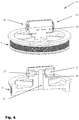
- FIG. 4 shows a further embodiment of a connection part 1c, in which also two air ports 18 and 19 are arranged in a bayonet fitting 20, also designed as a tube plug cartridges 21 and 22 of the same design, but formed in different dimensions.
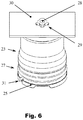
- FIG. 5 and 6 show in synopsis, an embodiment of the prior art, which once again illustrates the principle of a connection of an air spring 23 between not shown sprung and unsprung mass.
- the air spring 23 is clamped between the upper connection plate / air spring cover 24 and air spring piston 25 by means of clamping rings 26 and 27.
- One recognizes in the Fig. 5 clearly the bayonet lock with the mounting pin 28 which is inserted through the recess 29 of the mounting plate 30 and the fastening part to the seat, then, as in Fig. 6 shown rotated by 90 ° and usually then attached to the piston side.
- the bayonet wings of the mounting pin now lie on the mounting plate and it can also be transmitted to the mounting plate tensile forces.
- the air port 31 is usually attached to the lower end of the air spring piston.
Landscapes
- Engineering & Computer Science (AREA)
- General Engineering & Computer Science (AREA)
- Mechanical Engineering (AREA)
- Life Sciences & Earth Sciences (AREA)
- Transportation (AREA)
- Soil Sciences (AREA)
- Environmental Sciences (AREA)
- Aviation & Aerospace Engineering (AREA)
- Chemical & Material Sciences (AREA)
- Combustion & Propulsion (AREA)
- Vehicle Body Suspensions (AREA)
- Fluid-Damping Devices (AREA)
Description
- Die Erfindung betrifft eine Luftfeder mit einem Luftfederbalg aus elastomerem Material, der an den seinen Balgenden mit Hilfe von Anschlussteilen zwischen gefederter und ungefederter Masse bzw. zwischen gefederter Masse und einem umgebenden Rahmen eingespannt und über die Anschlussteile an den Befestigungsteilen der gefederten oder ungefederten Masse angelenkt ist, wobei die Anschlussteile und der Luftfederbalg den unter Innendruck stehenden und das Luftfedervolumen beinhaltenden Arbeitsraum umschließen und der Arbeitsraum mit mindestens einem in den Anschlussteilen vorgesehenen Luftanschluss in Verbindung steht.
- Luftfedern dieser Art sind im Stand der Technik umfassend bekannt und werden insbesondere bei Fahrzeugen, hier bei Lastkraftwagen ebenso wie bei größeren Personenkraftwagen, bei verschiedenen Federungsaufgaben eingesetzt. Üblicherweise werden solche Luftfedern in Fahrwerksfederungen eingesetzt, aber auch zur Federung für von Fahrersitzen in Nutzfahrzeugen oder zur Federung von Kabinen/Fahrerkabinen gegenüber dem Fahrzeugrahmen.
- Zur einfachen Montage werden solche Luftfedern insbesondere bei Fahrersitzen, Kabinenlagerungen und Achsanwendungen häufig mit einer Bajonettverriegelung am Luftfederdeckel ausgerüstet. Durch diese robuste und einfache Verriegelung wird eine Befestigungsverschraubung überflüssig.
- Die Luftfedern sind an eine Luftversorgung angeschlossen, üblicherweise über Schläuche und/oder Luftleitungen. Die Luftversorgung erfolgt in aller Regel über einen im Fahrzeug befindlichen Druckspeicher, der mithilfe eines Kompressors befüllt wird und dann über eine Steuerung die Luftversorgung für die einzelnen Federungen bereitstellt. Oft ist die Luftfedersteuerung in die übrige Fahrzeugsteuerung mit eingebunden.
- Zur sicheren und druckdichten Anbindung eines Luftversorgungsschlauches mit den einzelnen Luftfedern werden bei letzteren so genannte Luftanschlusselemente in Form von Einpresspatronen oder Stecknippel eingesetzt. Diese Elemente befinden sich üblicherweise im Luftfederkolben oder Luftfederdeckel, welche heute oft als Kunststoffspritzgussteil ausgeführt sind. Bei einigen Luftfedern sind auch mehr als ein Luftanschlusselement eingesetzt.
- In den Fällen, in denen Luftversorgungschläuche/Luftleitungen nach dem Einbau der Luftfeder angeschlossen werden, steht für die Positionierung der Luftanschlüsse örtlich wenig Platz zur Verfügung, sei es neben der üblichen recht flach gestalteten Bajonettverriegelung, sei es bei Luftfanschlüssen im oder am Abrollkolben. Das führt dazu, dass sich die Montage, also das Einstecken des Luftschlauches in Deckel oder Kolben der Luftfeder sich häufig als sehr schwierig erweist, da der Zugang zu den Luftanschlusselementen durch weitere Bauteile im Fahrzeug erschwert wird. Wenn beispielsweise eine solche Luftfeder mit einem Bajonettverschluss an die entsprechende komplementäre Aufnahme im Fahrersitz angeschlossen wird und diese Aufnahme sich direkt unter der Sitzschale befindet, so ist es schlichtweg unmöglich, den Luftanschluss nachträglich im Bereich zwischen Luftfederdeckel und Sitzschale zu montieren. In den Fällen, in denen die Luftversorgungschläuche/Luftleitungen vor dem Einbau der Luftfeder angeschossen sind, ist der Einbau durch die bereits angeschlossenen Schläuche oft noch schwieriger, da letztere natürlich das Manipulieren des zusammengesetzten Bauteils erschweren. In beiden Fällen ist eine nachträgliche Wartung oder ein nachträglicher Austausch der Schläuche natürlich überaus aufwendig.
- Das Dokument
US 2006/055094 A1 wird als nächstliegender Stand der Technik betrachtet und es beschreibt eine Luftfeder entsprechend dem Oberbegriff des Anspruchs 1. - Für die Erfindung bestand also die Aufgabe, eine Luftfeder bereitzustellen, deren Konstruktion eine einfache Montage der Luftleitungen in auch schwierigen Einbausituationen erlaubt und die im Übrigen mit den im Stand der Technik vorhandenen eingeübten Methoden und vorhandenen Montageteilen auskommt.,
- Gelöst wird diese Aufgabe durch die Merkmale des Hauptanspruchs. Weitere vorteilhafte Ausbildungen sind in den Unteransprüchen offenbart.
- Dabei ist mindestens eines der Anschlussteile mit einer lösbaren Schnapp- oder Rastverbindung an das zugehörige Befestigungsteil angeschlossen ist und die Schnapp- oder Rastverbindung als solche beinhaltet mindestens einen Luftanschluss bzw. ein Luftanschlusselement, an den eine Zuleitung oder ein Schlauch für die Druckluftzufuhr angeschlossen ist. Die Integration von Luftanschlusselementen in der Schnapp- oder Rastverbindung ermöglicht es, dass Bauraum, der für die Verriegelung zur Verfügung steht, auch für die Luftzufuhr genutzt werden kann. Die Montage des Luftzufuhrschlauches kann dadurch nach Montage der Luftfeder in leichter zugänglichen Bereichen erfolgen.
- Erfindungsgemäß ist die Schnapp- oder Rastverbindung zwischen Anschlussteil und Befestigungsteil als Bajonettverschluss ausgebildet, so dass die Montage-und Bewegungsabläufe im Grunde dieselben sind, die aus dem Stand der Technik in den entsprechenden Betrieben bekannt sind. Dabei werden die Teile in bekannter Weise einfach durch Ineinanderstecken und gegenseitiges Verdrehen verbunden und entsprechend wieder gelöst.
- Eine vorteilhafte Ausbildung besteht darin, dass der Luftanschluss als Steckverbindung oder Steckkupplung ausgebildet ist oder als Teil einer Steckverbindung oder Steckkupplung, deren komplementärer Teil sich an der Zuleitung oder am Schlauch befindet. Insbesondere mit einer Ausführung, in der der Luftanschluss ein Luftanschlusselement aufweist, welches als Buchse oder Steckpatrone in der Schnapp- oder Rastverbindung bzw. im Bajonettverschluss angeordnet ist, vereinfacht man nicht nur die Montage im Fahrzeug und erleichtert die Wartung und Instandhaltung, es wir auch eine einfachere Herstellung ermöglicht, bei der lediglich die Buchse oder Steckpatrone z. B. als präzises und eng toleriertes Drehteil hergestellt wird und nicht der gesamte Luftfederdeckel bearbeitet werden muss.
- Häufig werden zur Erhöhung des Schwingungskomforts an die Luftfeder auch Behälter mit einem Zusatzvolumen für das Federmedium Luft angeschlossen. Eine vorteilhafte Weiterbildung der Erfindung besteht dann darin, dass die Schnapp- oder Rastverbindung mehrere Luftanschlüsse aufweist, vorzugsweise einen Luftanschluss zur Befüllung und Entlüftung des Arbeitsraumes und einen Luftanschluss zur Verbindung des Arbeitsraumes mit einem Zusatzvolumen oder weiteren Federvolumina.
- Für eine optimale Funktion ist es vorteilhaft, wenn diese Zusatzvolumenbehälter mit einem Schlauch größeren Durchmessers mit der Luftfeder verbunden werden. Diesen Anwendungen dient insbesondere eine weitere vorteilhafte Ausbildung, die darin besteht, dass die Schnapp- oder Rastverbindung mehrere unterschiedliche Luftanschlüsse bzw. Luftanschlusselemente aufweist, wobei die Luftanschlüsse bzw. Luftanschlusselemente unterschiedliche Dimensionen und/oder unterschiedliche Ausbildungen zur Verbindung mit Zuleitungen oder Schläuchen aufweisen. Damit können auf einfache Weise unterschiedliche Luftanschlussdurchmesser realisiert werden.
- Besonders vorteilhaft lässt sich eine solche Luftfeder zur Lagerung bzw. Federung eines Fahrersitzes in einem Fahrzeug oder einer Fahrerkabine in einem Fahrzeugrahmen verwenden, da hier oft die Einbauverhältnisse besonders eng sind.
- Eine weitere vorteilhafte Anwendung einer solchen Luftfeder besteht in ihrem Einsatz als Aktuator in Fahrwerken landwirtschaftlicher Geräte oder Maschinen, hier insbesondere als Aktuator, der die Räder eines landwirtschaftlichen Fahrzeugs mehr oder weniger stark auf den Boden gedrückt. Ein Beispiel hierfür ist der Einsatz einer solchen Luftfeder in einer Saemaschine mit einer Vielzahl von Rädern, die im Sinne einer optimalen Lastverteilung durch an den Rädern bzw. im Fahrwerk angeordnete erfindungsgemäße Luftfedern als Aktuatoren in Bodenkontakt gehalten werden. In solchen Einsatzfällen ist nämlich der zur Verfügung stehende Bauraum ein genauso wichtiges Kriterium wie die nachträgliche einfache Zugänglichkeit solcher Elemente bei der Wartung und bei der Instandhaltung.
- Anhand eines Ausführungsbeispiels soll die Erfindung näher erläutert werden. Es zeigen
- Fig. 1
- Ein oberes Anschlussteil einer erfindungsgemäßen Luftfeder miz einem in einem Bajonettverschluss integrierten Luftanschluss,
- Fig. 2
- eine weitere Ausführung eines Anschlussteils, bei der der Bajonettverschluss zwei Luftanschlüsse aufweist,
- Fig. 3
- eine andere Ausführung eines Anschlussteils, bei dem in einem Bajonettverschluss zwei Luftanschlüsse vorhanden sind,
- Fig. 4
- eine weitere Ausführung eines Anschlussteils bei dem zwei Luftanschlüsse unterschiedlicher Dimensionen in einem Bajonettverschluss angeordnet sind,
- Fig. 5 und 6
- perspektivische Skizzen einer Ausführung aus dem Stand der Technik.
-
Fig. 1 zeigt ein oberes Anschlussteil 1, nämlich den Deckel/Luftfederdeckel einer Luftfeder für eine Sitzfederung. Im oberen Teil derFigur 1 ist eine perspektivische Ansicht dargestellt, während im unteren Teil derFig. 1 dieselbe perspektivische Ansicht in einer Schnittdarstellung zu sehen ist. Gleiche Darstellungsarten finden sich ebenfalls in denFig. 2 ,3 und4 . Die Sitz-Luftfeder ist mit Hilfe dieses Anschlussteils 1 / Luftfederdeckels an eine hier nicht näher dargestellte gefederte Masse, nämlich einen Sitz angeschlossen. - Das Anschlussteil bzw. der Luftfederdeckel ist mit einer lösbaren Rastverbindung, hier einem Bajonettverschluss 2 an das zugehörige Befestigungsteil am Sitz angeschlossen. Dabei werden Anschlussteil/Luftfederdeckel 1 und Befestigungsteil einfach durch Ineinanderstecken und gegenseitiges Verdrehen verbunden. Der Bajonettverschluss 2 weist einen integrierten Luftanschluss 3 auf, an den eine hier nicht näher dargestellte Zuleitung für die Druckluftzufuhr der Luftfeder angeschlossen ist.
- Der Luftanschluss 3 ist als Teil einer Steckkupplung ausgebildet, nämlich als Muffenende einer Steckkupplung und weist ein Luftanschlusselement 4 auf, welches als Steckpatrone im Bajonettverschluss 2 angeordnet ist, eine so genannte Schlauchsteckpatrone. Der komplementärere Teil, d.h. das Einsteckende befindet sich an einem hier nicht näher dargestellten Ende eines Schlauches für die Luftzuleitung.
- Das Anschlussteil 1 weist einen profilierten Randbereich 5 auf, an den der in dieser Figur nicht dargestellte Luftfederbalg mithilfe von Spannringen befestigt wird. Das von den Anschlussteilen und dem Luftfederbalg umschlossene und unter Innendruck stehende Luftfedervolumen steht über die Kanalbohrung 6 im oberen Anschlussteil mit dem Luftanschluss in Verbindung.
-
Fig. 2 zeigt eine weitere Ausführung eines Anschlussteils 1a, bei der der Bajonettverschluss 7 zwei Luftanschlüsse 8 und 9 aufweist, die miteinander in Verbindung stehen und über die mehrere Luftfedern parallel angeschlossen werden können. Ansonsten ist die Bauweise ähnlich der in derFig. 1 gezeigten Bauweise. Auch hier sind die Luftanschlüsse 8 und 9 als Muffenende einer Steckkupplung ausgebildet und weisen Luftanschlusselemente 10 und 11 auf, welches als Schlauchsteckpatronen im Bajonettverschluss 7 angeordnet sind. - Auch hier findet sich der profilierten Randbereich 5 zur Befestigung eines Luftfederbalgs mithilfe von Spannringen sowie eine Kanalbohrung 6 zur Verbindung des Arbeitsraumes mit dem Luftanschluss. Beide Luftanschlusselemente 10 und 11 sind ausgeführt als Schlauchsteckpatronen mit gleicher Dimension und Bauart.
-
Figur 3 zeigt eine andere Ausführung eines Anschlussteils 1b, bei dem in einem Bajonettverschluss 12 zwei Luftanschlüsse 13 und 14 vorhanden sind, die ähnlich ausgeführt sind wie die in derFigur 2 dargestellten Luftanschlüsse. Die hier gezeigte als Steckkupplung ausgebildet Steckverbindung weist jedoch Luftanschlusselemente 15 und 16 auf, die mit Federclips 17, d.h. gebogenen Federdrähten als Befestigungsklammern fixiert werden. -
Figur 4 zeigt eine weitere Ausführung eines Anschlussteils 1c, bei dem ebenfalls zwei Luftanschlüsse 18 und 19 in einem Bajonettverschluss 20 angeordnet sind, ebenfalls ausgeführt als Schlauchsteckpatronen 21 und 22 gleicher Bauart, jedoch ausgebildet in unterschiedlichen Dimensionen. -
Figur 5 und6 zeigen in der Zusammenschau eine Ausführung aus dem Stand der Technik, die noch einmal das Prinzip eines Anschlusses einer Luftfeder 23 zwischen hier nicht näher dargestellte gefederter und ungefederter Masse verdeutlicht. Links in derFigur 5 ist der Zustand vor der Montage dargestellt während rechts der Zustand nach Montage ersichtlich ist. Die Luftfeder 23 ist zwischen oberer Anschlussplatte/Luftfederdeckel 24 und Luftfederkolben 25 mithilfe von Spannringen 26 und 27 eingespannt. Man erkennt in derFig. 5 deutlich den Bajonettverschluss mit dem Montagezapfen 28, der durch die Aussparung 29 des Befestigungsbleches 30 bzw. des Befestigungsteils am Sitz hindurch gesteckt wird, dann, wie inFig. 6 gezeigt, um 90° gedreht und üblicherweise danach auf der Kolbenseite befestigt wird. Die Bajonettflügel des Montagezapfens liegen jetzt am Befestigungsblech an und es können auch Zugkräfte auf das Befestigungsblech übertragen werden. In solchen, im Stand der Technik bekannten Ausführungen, ist der Luftanschluss 31 üblicherweise am unteren Ende des Luftfederkolbens angebracht. -
- 1, 1a, 1b, 1c
- Anschlussteil
- 2
- Bajonettverschluss
- 3
- Luftanschluss
- 4
- Luftanschlusselement
- 5
- Profilierter Randbereich
- 6
- Kanalbohrung
- 7
- Bajonettverschluss
- 8
- Luftanschluss
- 9
- Luftanschluss
- 10
- Luftanschlusselement
- 11
- Luftanschlusselement
- 12
- Bajonettverschluss
- 13
- Luftanschluss
- 14
- Luftanschluss
- 15
- Luftanschlusselement
- 16
- Luftanschlusselement
- 17
- Federclip
- 18
- Luftanschluss
- 19
- Luftanschluss
- 20
- Bajonettverschluss
- 21
- Schlauchsteckpatrone
- 22
- Schlauchsteckpatrone
- 23
- Luftfeder
- 24
- Luftfederdeckel (oberes Anschlussteil)
- 25
- Luftfederkolben (unteres Anschlussteil)
- 26
- Spannring
- 27
- Spannring
- 28
- Montagezapfen
- 29
- Aussparung
- 30
- Befestigungsblech
- 31
- Luftanschluss
Claims (8)
- Luftfeder mit einem Luftfederbalg aus elastomerem Material, der an den seinen Balgenden mit Hilfe von Anschlussteilen (1, 1a, 1b, 1c) zwischen gefederter und ungefederter Masse eingespannt und über die Anschlussteile an Befestigungsteilen der gefederten und ungefederten Masse anschließbar ist, wobei die Anschlussteile (1, 1a, 1b, 1c) und der Luftfederbalg den unter Innendruck stehenden und das Luftfedervolumen beinhaltenden Arbeitsraum umschließen und der Arbeitsraum mit mindestens einem in den Anschlussteilen vorgesehenen Luftanschluss (3, 8, 9, 13, 14, 18, 19) in Verbindung steht, dadurch gekennzeichnet, dass mindestens eines der Anschlussteile (1, 1a, 1b, 1c) mit einer als Bajonettverschluss (2) ausgebildeten Rastverbindung an das zugehörige Befestigungsteil anschließbar ist und Bajonettverschluss (2) mindestens einen Luftanschluss (3, 8, 9, 13, 14, 18, 19,) beinhaltet, an den eine Zuleitung oder ein Schlauch für die Druckluftzufuhr angeschlossen ist.
- Luftfeder nach Anspruch 1, bei der der Bajonettverschluss mehrere Luftanschlüsse aufweist (8, 9, 13, 14, 18, 19,), vorzugsweise einen Luftanschluss zur Befüllung und Entlüftung des Arbeitsraumes und einen Luftanschluss zur Verbindung des Arbeitsraumes mit einem Zusatzvolumen oder weiteren Federvolumina.
- Luftfeder nach einem der Ansprüche 1 oder 2, bei der der Luftanschluss (3, 8, 9, 13, 14, 18, 19,) als Steckverbindung oder Steckkupplung ausgebildet ist oder als Teil einer Steckverbindung oder Steckkupplung, deren komplementärer Teil sich an der Zuleitung oder am Schlauch befindet.
- Luftfeder nach einem der Ansprüche 1 bis 3, bei der der Luftanschluss (3, 8, 9, 13, 14, 18, 19,) ein Luftanschlusselement (4, 10, 11, 15, 16, 21, 22) aufweist, welches als Buchse oder Steckpatrone in der Schnapp- oder Rastverbindung bzw. im Bajonettverschluss angeordnet ist.
- Luftfeder nach einem der Ansprüche 1 bis 4, bei der der Bajonettverschluss mehrere unterschiedliche Luftanschlüsse (18, 19) bzw. Luftanschlusselemente (21, 22) aufweist, wobei die Luftanschlüsse bzw. Luftanschlusselemente unterschiedliche Dimensionen und/oder unterschiedliche Ausbildungen zur Verbindung mit Zuleitungen oder Schläuchen aufweisen.
- Verwendung einer Luftfeder nach einem der Ansprüche 1 bis 6 zur Lagerung bzw. Federung eines Fahrersitzes in einem Fahrzeug dadurch gekennzeichnet, dass mindestens eines der Anschlussteile mittels der als Bajonettverschluss ausgebildeten Rastverbindung an das zugehörige Befestigungsteil angeschlossen ist.
- Verwendung einer Luftfeder nach einem der Ansprüche 1 bis 6 zur Lagerung bzw. Federung einer Fahrerkabine in einem Fahrzeugrahmen dadurch gekennzeichnet, dass mindestens eines der Anschlussteile mittels der als Bajonettverschluss ausgebildeten Rastverbindung an das zugehörige Befestigungsteil angeschlossen ist.
- Verwendung einer Luftfeder nach einem der Ansprüche 1 bis 6 als federnder Aktuator in Fahrwerken landwirtschaftlicher Geräte dadurch gekennzeichnet, dass mindestens eines der Anschlussteile mittels der als Bajonettverschluss ausgebildeten Rastverbindung an das zugehörige Befestigungsteil angeschlossen ist.
Applications Claiming Priority (2)
| Application Number | Priority Date | Filing Date | Title |
|---|---|---|---|
| DE102015215735.0A DE102015215735A1 (de) | 2015-08-18 | 2015-08-18 | Luftfeder und ihre Verwendung |
| PCT/EP2016/060365 WO2017028970A1 (de) | 2015-08-18 | 2016-05-10 | Luftfeder und ihre verwendung |
Publications (2)
| Publication Number | Publication Date |
|---|---|
| EP3338005A1 EP3338005A1 (de) | 2018-06-27 |
| EP3338005B1 true EP3338005B1 (de) | 2019-12-04 |
Family
ID=55963356
Family Applications (1)
| Application Number | Title | Priority Date | Filing Date |
|---|---|---|---|
| EP16721801.5A Active EP3338005B1 (de) | 2015-08-18 | 2016-05-10 | Luftfeder und ihre verwendung |
Country Status (4)
| Country | Link |
|---|---|
| US (1) | US10920846B2 (de) |
| EP (1) | EP3338005B1 (de) |
| DE (1) | DE102015215735A1 (de) |
| WO (1) | WO2017028970A1 (de) |
Families Citing this family (3)
| Publication number | Priority date | Publication date | Assignee | Title |
|---|---|---|---|---|
| DE102017109806B4 (de) | 2017-05-08 | 2020-03-19 | Saf-Holland Gmbh | Luftfedersystem mit einer Luftfedereinrichtung und Verfahren zur Montage eines Luftfedersystems |
| EP3486520A1 (de) * | 2017-11-21 | 2019-05-22 | Miro Gudzulic | Luftfederanlage für ein kraftfahrzeug |
| CN110809929B (zh) * | 2019-11-28 | 2022-08-02 | 贵州理工学院 | 一种农机用多功能安装组件 |
Family Cites Families (12)
| Publication number | Priority date | Publication date | Assignee | Title |
|---|---|---|---|---|
| US4453747A (en) * | 1982-06-01 | 1984-06-12 | Bimba Charles W | Connector system for flexible tubing |
| US5326082A (en) * | 1992-06-10 | 1994-07-05 | Bridgestone/Firestone, Inc. | Self locking, snap mounted attachment device |
| DE59806194D1 (de) * | 1997-05-28 | 2002-12-12 | Phoenix Ag | Luftfedersystem |
| US6554323B1 (en) * | 1999-07-26 | 2003-04-29 | Voss Automotive Gmbh | Plug connector for quick-release connection of pressurized lines |
| US6398179B1 (en) * | 2000-01-19 | 2002-06-04 | General Motors Corporation | Fastener-less spring assembly |
| US6698730B2 (en) * | 2001-10-04 | 2004-03-02 | Bfs Diversified Products, Llc | Dual rate air spring |
| US6746004B2 (en) * | 2001-12-05 | 2004-06-08 | Bfs Diversified Products, Llc | Vehicle air spring assembly |
| US20060055094A1 (en) * | 2004-09-15 | 2006-03-16 | Goodyear Tire And Rubber Company | Air spring mount with snap-in attachment |
| US20060267257A1 (en) * | 2005-05-24 | 2006-11-30 | Bfs Diversified Products, Llc | Air spring assembly with non-threaded connection |
| US8979074B2 (en) * | 2010-01-18 | 2015-03-17 | Firestone Industrial Products, Llc | Air springs with improved high temperature performance |
| PL2696095T3 (pl) * | 2012-08-07 | 2019-04-30 | Vibracoustic Cv Air Springs Gmbh | Sprężyna pneumatyczna ze złączami do mocowania końca miecha |
| US10005333B2 (en) * | 2013-05-28 | 2018-06-26 | Firestone Industrial Products Company, Llc | End member assemblies and travel-restraint assemblies as well as gas spring assemblies including same |
-
2015
- 2015-08-18 DE DE102015215735.0A patent/DE102015215735A1/de not_active Withdrawn
-
2016
- 2016-05-10 WO PCT/EP2016/060365 patent/WO2017028970A1/de not_active Ceased
- 2016-05-10 EP EP16721801.5A patent/EP3338005B1/de active Active
-
2018
- 2018-02-20 US US15/900,547 patent/US10920846B2/en active Active
Non-Patent Citations (1)
| Title |
|---|
| None * |
Also Published As
| Publication number | Publication date |
|---|---|
| DE102015215735A1 (de) | 2017-02-23 |
| EP3338005A1 (de) | 2018-06-27 |
| WO2017028970A1 (de) | 2017-02-23 |
| US10920846B2 (en) | 2021-02-16 |
| US20180172103A1 (en) | 2018-06-21 |
Similar Documents
| Publication | Publication Date | Title |
|---|---|---|
| DE102015205606B4 (de) | Dämpferstangenbuchsen sowie Gasfeder- und Dämpferanordnungen und Verfahren damit | |
| DE112012000581B4 (de) | Gasfederkolben sowie diesen beinhaltende Gasfederanordnung, System,Einbausatz und Verfahren | |
| EP2780607B1 (de) | Luftfeder | |
| DE102015016142B4 (de) | Elastisches Lager zur Verbindung zweier Bauteile | |
| EP3736146A1 (de) | Energieversorgungseinheit für aktives fahrwerksystem | |
| DE112013000742T5 (de) | Anschlagpuffer, Endelement, Gasfederbaugruppe und Zusammenbauverfahren | |
| WO2017028970A1 (de) | Luftfeder und ihre verwendung | |
| DE102015210151A1 (de) | Verfahren zur Montage der Schwingungsdämpfer eines zweispurigen zweiachsigen Fahrzeugs | |
| EP3574230B1 (de) | Luftfederbalg | |
| DE102018005306A1 (de) | Kopplungsvorrichtung für einen Bremsfluidbehälter und Fahrzeugbremsanlage | |
| DE102015108484A1 (de) | Querblattfeder für ein Kraftfahrzeug sowie Achsanordnung mit einer Querblattfeder | |
| DE102017213935A1 (de) | Entkopplungseinheit und Wankstabilisator mit einer solchen Entkopplungseinheit | |
| DE112013004254T5 (de) | Endelemente und Gasfederanordnungen, die diese aufweisen | |
| DE102017211672A1 (de) | Verstelleinrichtung für ein Fahrwerk eines Kraftfahrzeuges sowie Hinterachslenkung | |
| DE102006022382A1 (de) | Vorrichtung und Verfahren zur Befestigung eines Wischermotors an ein Wischergestänge | |
| EP4442475A1 (de) | Hydraulikbaukasten | |
| DE10120324B4 (de) | Elektropneumatisches Doppelregelventil mit einer Dichtungsanordnung | |
| DE19619498A1 (de) | Vorrichtung zum Anschluß eines Teleskopzylinders an Fluid- und/oder Signalleitungen | |
| DE102017214202A1 (de) | Dämpferlager und Verfahren zur Montage einer Kolbenstange mit Kabelabgang an einem solchen | |
| DE112016004236T5 (de) | Zylindereinrichtung | |
| DE102009020249A1 (de) | Anordnung zur Fahrwerksstabilisierung | |
| DE102014223632A1 (de) | Hinterachse eines Kraftfahrzeugs sowie Kraftfahrzeug mit einer derartigen Hinterachse | |
| DE102023122143B4 (de) | Dämpfungsanordnung für eine Achse eines Kraftfahrzeugs und Kraftfahrzeug | |
| DE102011100660A1 (de) | Achsschenkelelement für einen Kraftwagen, insbesondere Nutzkraftwagen, sowie Antriebseinrichtung für einen Kraftwagen mit einem solchen Achsschenkelelement | |
| DE102018211542A1 (de) | Durchflussdruckänderungsdämpfer für eine bremsdruckgeregelte hydraulische Fahrzeugbremsanlage und Hydraulikblock eines Hydraulikaggregats einer bremsdruckgeregelten hydraulischen Fahrzeugbremsanlage |
Legal Events
| Date | Code | Title | Description |
|---|---|---|---|
| STAA | Information on the status of an ep patent application or granted ep patent |
Free format text: STATUS: THE INTERNATIONAL PUBLICATION HAS BEEN MADE |
|
| PUAI | Public reference made under article 153(3) epc to a published international application that has entered the european phase |
Free format text: ORIGINAL CODE: 0009012 |
|
| STAA | Information on the status of an ep patent application or granted ep patent |
Free format text: STATUS: REQUEST FOR EXAMINATION WAS MADE |
|
| 17P | Request for examination filed |
Effective date: 20180319 |
|
| AK | Designated contracting states |
Kind code of ref document: A1 Designated state(s): AL AT BE BG CH CY CZ DE DK EE ES FI FR GB GR HR HU IE IS IT LI LT LU LV MC MK MT NL NO PL PT RO RS SE SI SK SM TR |
|
| AX | Request for extension of the european patent |
Extension state: BA ME |
|
| DAV | Request for validation of the european patent (deleted) | ||
| DAX | Request for extension of the european patent (deleted) | ||
| GRAP | Despatch of communication of intention to grant a patent |
Free format text: ORIGINAL CODE: EPIDOSNIGR1 |
|
| STAA | Information on the status of an ep patent application or granted ep patent |
Free format text: STATUS: GRANT OF PATENT IS INTENDED |
|
| INTG | Intention to grant announced |
Effective date: 20190812 |
|
| GRAS | Grant fee paid |
Free format text: ORIGINAL CODE: EPIDOSNIGR3 |
|
| GRAA | (expected) grant |
Free format text: ORIGINAL CODE: 0009210 |
|
| STAA | Information on the status of an ep patent application or granted ep patent |
Free format text: STATUS: THE PATENT HAS BEEN GRANTED |
|
| AK | Designated contracting states |
Kind code of ref document: B1 Designated state(s): AL AT BE BG CH CY CZ DE DK EE ES FI FR GB GR HR HU IE IS IT LI LT LU LV MC MK MT NL NO PL PT RO RS SE SI SK SM TR |
|
| REG | Reference to a national code |
Ref country code: GB Ref legal event code: FG4D Free format text: NOT ENGLISH |
|
| REG | Reference to a national code |
Ref country code: CH Ref legal event code: EP |
|
| REG | Reference to a national code |
Ref country code: AT Ref legal event code: REF Ref document number: 1209805 Country of ref document: AT Kind code of ref document: T Effective date: 20191215 |
|
| REG | Reference to a national code |
Ref country code: DE Ref legal event code: R096 Ref document number: 502016007873 Country of ref document: DE |
|
| REG | Reference to a national code |
Ref country code: IE Ref legal event code: FG4D Free format text: LANGUAGE OF EP DOCUMENT: GERMAN |
|
| REG | Reference to a national code |
Ref country code: NL Ref legal event code: MP Effective date: 20191204 |
|
| REG | Reference to a national code |
Ref country code: LT Ref legal event code: MG4D |
|
| PG25 | Lapsed in a contracting state [announced via postgrant information from national office to epo] |
Ref country code: FI Free format text: LAPSE BECAUSE OF FAILURE TO SUBMIT A TRANSLATION OF THE DESCRIPTION OR TO PAY THE FEE WITHIN THE PRESCRIBED TIME-LIMIT Effective date: 20191204 Ref country code: BG Free format text: LAPSE BECAUSE OF FAILURE TO SUBMIT A TRANSLATION OF THE DESCRIPTION OR TO PAY THE FEE WITHIN THE PRESCRIBED TIME-LIMIT Effective date: 20200304 Ref country code: SE Free format text: LAPSE BECAUSE OF FAILURE TO SUBMIT A TRANSLATION OF THE DESCRIPTION OR TO PAY THE FEE WITHIN THE PRESCRIBED TIME-LIMIT Effective date: 20191204 Ref country code: LV Free format text: LAPSE BECAUSE OF FAILURE TO SUBMIT A TRANSLATION OF THE DESCRIPTION OR TO PAY THE FEE WITHIN THE PRESCRIBED TIME-LIMIT Effective date: 20191204 Ref country code: LT Free format text: LAPSE BECAUSE OF FAILURE TO SUBMIT A TRANSLATION OF THE DESCRIPTION OR TO PAY THE FEE WITHIN THE PRESCRIBED TIME-LIMIT Effective date: 20191204 Ref country code: NO Free format text: LAPSE BECAUSE OF FAILURE TO SUBMIT A TRANSLATION OF THE DESCRIPTION OR TO PAY THE FEE WITHIN THE PRESCRIBED TIME-LIMIT Effective date: 20200304 Ref country code: GR Free format text: LAPSE BECAUSE OF FAILURE TO SUBMIT A TRANSLATION OF THE DESCRIPTION OR TO PAY THE FEE WITHIN THE PRESCRIBED TIME-LIMIT Effective date: 20200305 |
|
| PG25 | Lapsed in a contracting state [announced via postgrant information from national office to epo] |
Ref country code: HR Free format text: LAPSE BECAUSE OF FAILURE TO SUBMIT A TRANSLATION OF THE DESCRIPTION OR TO PAY THE FEE WITHIN THE PRESCRIBED TIME-LIMIT Effective date: 20191204 Ref country code: RS Free format text: LAPSE BECAUSE OF FAILURE TO SUBMIT A TRANSLATION OF THE DESCRIPTION OR TO PAY THE FEE WITHIN THE PRESCRIBED TIME-LIMIT Effective date: 20191204 |
|
| PG25 | Lapsed in a contracting state [announced via postgrant information from national office to epo] |
Ref country code: AL Free format text: LAPSE BECAUSE OF FAILURE TO SUBMIT A TRANSLATION OF THE DESCRIPTION OR TO PAY THE FEE WITHIN THE PRESCRIBED TIME-LIMIT Effective date: 20191204 |
|
| PG25 | Lapsed in a contracting state [announced via postgrant information from national office to epo] |
Ref country code: NL Free format text: LAPSE BECAUSE OF FAILURE TO SUBMIT A TRANSLATION OF THE DESCRIPTION OR TO PAY THE FEE WITHIN THE PRESCRIBED TIME-LIMIT Effective date: 20191204 Ref country code: CZ Free format text: LAPSE BECAUSE OF FAILURE TO SUBMIT A TRANSLATION OF THE DESCRIPTION OR TO PAY THE FEE WITHIN THE PRESCRIBED TIME-LIMIT Effective date: 20191204 Ref country code: ES Free format text: LAPSE BECAUSE OF FAILURE TO SUBMIT A TRANSLATION OF THE DESCRIPTION OR TO PAY THE FEE WITHIN THE PRESCRIBED TIME-LIMIT Effective date: 20191204 Ref country code: RO Free format text: LAPSE BECAUSE OF FAILURE TO SUBMIT A TRANSLATION OF THE DESCRIPTION OR TO PAY THE FEE WITHIN THE PRESCRIBED TIME-LIMIT Effective date: 20191204 Ref country code: EE Free format text: LAPSE BECAUSE OF FAILURE TO SUBMIT A TRANSLATION OF THE DESCRIPTION OR TO PAY THE FEE WITHIN THE PRESCRIBED TIME-LIMIT Effective date: 20191204 Ref country code: PT Free format text: LAPSE BECAUSE OF FAILURE TO SUBMIT A TRANSLATION OF THE DESCRIPTION OR TO PAY THE FEE WITHIN THE PRESCRIBED TIME-LIMIT Effective date: 20200429 |
|
| PG25 | Lapsed in a contracting state [announced via postgrant information from national office to epo] |
Ref country code: SM Free format text: LAPSE BECAUSE OF FAILURE TO SUBMIT A TRANSLATION OF THE DESCRIPTION OR TO PAY THE FEE WITHIN THE PRESCRIBED TIME-LIMIT Effective date: 20191204 Ref country code: IS Free format text: LAPSE BECAUSE OF FAILURE TO SUBMIT A TRANSLATION OF THE DESCRIPTION OR TO PAY THE FEE WITHIN THE PRESCRIBED TIME-LIMIT Effective date: 20200404 Ref country code: SK Free format text: LAPSE BECAUSE OF FAILURE TO SUBMIT A TRANSLATION OF THE DESCRIPTION OR TO PAY THE FEE WITHIN THE PRESCRIBED TIME-LIMIT Effective date: 20191204 |
|
| REG | Reference to a national code |
Ref country code: DE Ref legal event code: R097 Ref document number: 502016007873 Country of ref document: DE |
|
| PLBE | No opposition filed within time limit |
Free format text: ORIGINAL CODE: 0009261 |
|
| STAA | Information on the status of an ep patent application or granted ep patent |
Free format text: STATUS: NO OPPOSITION FILED WITHIN TIME LIMIT |
|
| PG25 | Lapsed in a contracting state [announced via postgrant information from national office to epo] |
Ref country code: DK Free format text: LAPSE BECAUSE OF FAILURE TO SUBMIT A TRANSLATION OF THE DESCRIPTION OR TO PAY THE FEE WITHIN THE PRESCRIBED TIME-LIMIT Effective date: 20191204 |
|
| 26N | No opposition filed |
Effective date: 20200907 |
|
| PG25 | Lapsed in a contracting state [announced via postgrant information from national office to epo] |
Ref country code: PL Free format text: LAPSE BECAUSE OF FAILURE TO SUBMIT A TRANSLATION OF THE DESCRIPTION OR TO PAY THE FEE WITHIN THE PRESCRIBED TIME-LIMIT Effective date: 20191204 Ref country code: SI Free format text: LAPSE BECAUSE OF FAILURE TO SUBMIT A TRANSLATION OF THE DESCRIPTION OR TO PAY THE FEE WITHIN THE PRESCRIBED TIME-LIMIT Effective date: 20191204 |
|
| PG25 | Lapsed in a contracting state [announced via postgrant information from national office to epo] |
Ref country code: MC Free format text: LAPSE BECAUSE OF FAILURE TO SUBMIT A TRANSLATION OF THE DESCRIPTION OR TO PAY THE FEE WITHIN THE PRESCRIBED TIME-LIMIT Effective date: 20191204 Ref country code: LI Free format text: LAPSE BECAUSE OF NON-PAYMENT OF DUE FEES Effective date: 20200531 Ref country code: CH Free format text: LAPSE BECAUSE OF NON-PAYMENT OF DUE FEES Effective date: 20200531 Ref country code: IT Free format text: LAPSE BECAUSE OF FAILURE TO SUBMIT A TRANSLATION OF THE DESCRIPTION OR TO PAY THE FEE WITHIN THE PRESCRIBED TIME-LIMIT Effective date: 20191204 |
|
| REG | Reference to a national code |
Ref country code: BE Ref legal event code: MM Effective date: 20200531 |
|
| PG25 | Lapsed in a contracting state [announced via postgrant information from national office to epo] |
Ref country code: LU Free format text: LAPSE BECAUSE OF NON-PAYMENT OF DUE FEES Effective date: 20200510 |
|
| PG25 | Lapsed in a contracting state [announced via postgrant information from national office to epo] |
Ref country code: IE Free format text: LAPSE BECAUSE OF NON-PAYMENT OF DUE FEES Effective date: 20200510 |
|
| PG25 | Lapsed in a contracting state [announced via postgrant information from national office to epo] |
Ref country code: BE Free format text: LAPSE BECAUSE OF NON-PAYMENT OF DUE FEES Effective date: 20200531 |
|
| PG25 | Lapsed in a contracting state [announced via postgrant information from national office to epo] |
Ref country code: TR Free format text: LAPSE BECAUSE OF FAILURE TO SUBMIT A TRANSLATION OF THE DESCRIPTION OR TO PAY THE FEE WITHIN THE PRESCRIBED TIME-LIMIT Effective date: 20191204 Ref country code: MT Free format text: LAPSE BECAUSE OF FAILURE TO SUBMIT A TRANSLATION OF THE DESCRIPTION OR TO PAY THE FEE WITHIN THE PRESCRIBED TIME-LIMIT Effective date: 20191204 Ref country code: CY Free format text: LAPSE BECAUSE OF FAILURE TO SUBMIT A TRANSLATION OF THE DESCRIPTION OR TO PAY THE FEE WITHIN THE PRESCRIBED TIME-LIMIT Effective date: 20191204 |
|
| PG25 | Lapsed in a contracting state [announced via postgrant information from national office to epo] |
Ref country code: MK Free format text: LAPSE BECAUSE OF FAILURE TO SUBMIT A TRANSLATION OF THE DESCRIPTION OR TO PAY THE FEE WITHIN THE PRESCRIBED TIME-LIMIT Effective date: 20191204 |
|
| REG | Reference to a national code |
Ref country code: AT Ref legal event code: MM01 Ref document number: 1209805 Country of ref document: AT Kind code of ref document: T Effective date: 20210510 |
|
| PG25 | Lapsed in a contracting state [announced via postgrant information from national office to epo] |
Ref country code: AT Free format text: LAPSE BECAUSE OF NON-PAYMENT OF DUE FEES Effective date: 20210510 |
|
| PGFP | Annual fee paid to national office [announced via postgrant information from national office to epo] |
Ref country code: DE Payment date: 20250531 Year of fee payment: 10 |
|
| PGFP | Annual fee paid to national office [announced via postgrant information from national office to epo] |
Ref country code: GB Payment date: 20250527 Year of fee payment: 10 |
|
| PGFP | Annual fee paid to national office [announced via postgrant information from national office to epo] |
Ref country code: FR Payment date: 20250528 Year of fee payment: 10 |