EP3720716B1 - Procédé pour le séchage d'un substrat, module de séchage pour la mise en oeuvre du procédé ainsi que système de séchage - Google Patents
Procédé pour le séchage d'un substrat, module de séchage pour la mise en oeuvre du procédé ainsi que système de séchage Download PDFInfo
- Publication number
- EP3720716B1 EP3720716B1 EP18815146.8A EP18815146A EP3720716B1 EP 3720716 B1 EP3720716 B1 EP 3720716B1 EP 18815146 A EP18815146 A EP 18815146A EP 3720716 B1 EP3720716 B1 EP 3720716B1
- Authority
- EP
- European Patent Office
- Prior art keywords
- substrate
- process gas
- infrared
- transport direction
- dryer
- Prior art date
- Legal status (The legal status is an assumption and is not a legal conclusion. Google has not performed a legal analysis and makes no representation as to the accuracy of the status listed.)
- Active
Links
- 238000000034 method Methods 0.000 title claims description 222
- 239000000758 substrate Substances 0.000 title claims description 171
- 238000001035 drying Methods 0.000 title claims description 55
- 230000008569 process Effects 0.000 claims description 189
- 230000005855 radiation Effects 0.000 claims description 17
- 238000000605 extraction Methods 0.000 claims description 12
- 230000009471 action Effects 0.000 claims description 10
- 238000007599 discharging Methods 0.000 claims 1
- 239000007789 gas Substances 0.000 description 167
- 238000007639 printing Methods 0.000 description 59
- 239000000463 material Substances 0.000 description 31
- 239000000126 substance Substances 0.000 description 18
- 230000003993 interaction Effects 0.000 description 17
- 238000010438 heat treatment Methods 0.000 description 13
- 238000011282 treatment Methods 0.000 description 12
- 230000000694 effects Effects 0.000 description 9
- 239000002904 solvent Substances 0.000 description 9
- 239000000976 ink Substances 0.000 description 8
- XLYOFNOQVPJJNP-UHFFFAOYSA-N water Substances O XLYOFNOQVPJJNP-UHFFFAOYSA-N 0.000 description 8
- 238000001704 evaporation Methods 0.000 description 7
- 230000008020 evaporation Effects 0.000 description 7
- 230000015572 biosynthetic process Effects 0.000 description 5
- 238000001816 cooling Methods 0.000 description 5
- 239000007788 liquid Substances 0.000 description 5
- 238000010521 absorption reaction Methods 0.000 description 4
- 239000011111 cardboard Substances 0.000 description 3
- 238000013461 design Methods 0.000 description 3
- 239000012530 fluid Substances 0.000 description 3
- 239000000123 paper Substances 0.000 description 3
- 231100000331 toxic Toxicity 0.000 description 3
- 230000002588 toxic effect Effects 0.000 description 3
- VYPSYNLAJGMNEJ-UHFFFAOYSA-N Silicium dioxide Chemical compound O=[Si]=O VYPSYNLAJGMNEJ-UHFFFAOYSA-N 0.000 description 2
- TZCXTZWJZNENPQ-UHFFFAOYSA-L barium sulfate Chemical compound [Ba+2].[O-]S([O-])(=O)=O TZCXTZWJZNENPQ-UHFFFAOYSA-L 0.000 description 2
- 230000001276 controlling effect Effects 0.000 description 2
- 239000000112 cooling gas Substances 0.000 description 2
- 230000006872 improvement Effects 0.000 description 2
- 239000012535 impurity Substances 0.000 description 2
- 239000004615 ingredient Substances 0.000 description 2
- 230000004048 modification Effects 0.000 description 2
- 238000012986 modification Methods 0.000 description 2
- 239000011347 resin Substances 0.000 description 2
- 229920005989 resin Polymers 0.000 description 2
- 210000002023 somite Anatomy 0.000 description 2
- 238000001179 sorption measurement Methods 0.000 description 2
- 239000002966 varnish Substances 0.000 description 2
- 238000010792 warming Methods 0.000 description 2
- OKTJSMMVPCPJKN-UHFFFAOYSA-N Carbon Chemical compound [C] OKTJSMMVPCPJKN-UHFFFAOYSA-N 0.000 description 1
- 206010013710 Drug interaction Diseases 0.000 description 1
- 206010013786 Dry skin Diseases 0.000 description 1
- 230000001133 acceleration Effects 0.000 description 1
- 239000000853 adhesive Substances 0.000 description 1
- 230000001070 adhesive effect Effects 0.000 description 1
- 238000013459 approach Methods 0.000 description 1
- 239000011230 binding agent Substances 0.000 description 1
- 229910052799 carbon Inorganic materials 0.000 description 1
- 238000006243 chemical reaction Methods 0.000 description 1
- 239000000356 contaminant Substances 0.000 description 1
- 238000004132 cross linking Methods 0.000 description 1
- 238000009792 diffusion process Methods 0.000 description 1
- 238000005265 energy consumption Methods 0.000 description 1
- 239000011888 foil Substances 0.000 description 1
- 239000011261 inert gas Substances 0.000 description 1
- 238000007641 inkjet printing Methods 0.000 description 1
- 238000009434 installation Methods 0.000 description 1
- 238000007645 offset printing Methods 0.000 description 1
- 239000003921 oil Substances 0.000 description 1
- 238000013021 overheating Methods 0.000 description 1
- 230000003647 oxidation Effects 0.000 description 1
- 238000007254 oxidation reaction Methods 0.000 description 1
- 239000003973 paint Substances 0.000 description 1
- 239000011087 paperboard Substances 0.000 description 1
- 231100000614 poison Toxicity 0.000 description 1
- 238000006116 polymerization reaction Methods 0.000 description 1
- 238000012545 processing Methods 0.000 description 1
- 239000000047 product Substances 0.000 description 1
- 230000001105 regulatory effect Effects 0.000 description 1
- 239000003440 toxic substance Substances 0.000 description 1
- 238000012546 transfer Methods 0.000 description 1
- 230000007704 transition Effects 0.000 description 1
- WFKWXMTUELFFGS-UHFFFAOYSA-N tungsten Chemical compound [W] WFKWXMTUELFFGS-UHFFFAOYSA-N 0.000 description 1
- 229910052721 tungsten Inorganic materials 0.000 description 1
- 239000010937 tungsten Substances 0.000 description 1
- 238000011144 upstream manufacturing Methods 0.000 description 1
- 238000009423 ventilation Methods 0.000 description 1
Images
Classifications
-
- B—PERFORMING OPERATIONS; TRANSPORTING
- B41—PRINTING; LINING MACHINES; TYPEWRITERS; STAMPS
- B41F—PRINTING MACHINES OR PRESSES
- B41F23/00—Devices for treating the surfaces of sheets, webs, or other articles in connection with printing
- B41F23/04—Devices for treating the surfaces of sheets, webs, or other articles in connection with printing by heat drying, by cooling, by applying powders
- B41F23/0403—Drying webs
- B41F23/0436—Drying webs using a combination of radiation, conduction or convection
-
- B—PERFORMING OPERATIONS; TRANSPORTING
- B41—PRINTING; LINING MACHINES; TYPEWRITERS; STAMPS
- B41F—PRINTING MACHINES OR PRESSES
- B41F23/00—Devices for treating the surfaces of sheets, webs, or other articles in connection with printing
- B41F23/04—Devices for treating the surfaces of sheets, webs, or other articles in connection with printing by heat drying, by cooling, by applying powders
- B41F23/0403—Drying webs
- B41F23/0406—Drying webs by radiation
- B41F23/0413—Infra-red dryers
-
- B—PERFORMING OPERATIONS; TRANSPORTING
- B41—PRINTING; LINING MACHINES; TYPEWRITERS; STAMPS
- B41F—PRINTING MACHINES OR PRESSES
- B41F23/00—Devices for treating the surfaces of sheets, webs, or other articles in connection with printing
- B41F23/04—Devices for treating the surfaces of sheets, webs, or other articles in connection with printing by heat drying, by cooling, by applying powders
- B41F23/044—Drying sheets, e.g. between two printing stations
- B41F23/045—Drying sheets, e.g. between two printing stations by radiation
- B41F23/0456—Drying sheets, e.g. between two printing stations by radiation by infrared dryers
-
- F—MECHANICAL ENGINEERING; LIGHTING; HEATING; WEAPONS; BLASTING
- F26—DRYING
- F26B—DRYING SOLID MATERIALS OR OBJECTS BY REMOVING LIQUID THEREFROM
- F26B13/00—Machines and apparatus for drying fabrics, fibres, yarns, or other materials in long lengths, with progressive movement
-
- F—MECHANICAL ENGINEERING; LIGHTING; HEATING; WEAPONS; BLASTING
- F26—DRYING
- F26B—DRYING SOLID MATERIALS OR OBJECTS BY REMOVING LIQUID THEREFROM
- F26B15/00—Machines or apparatus for drying objects with progressive movement; Machines or apparatus with progressive movement for drying batches of material in compact form
-
- F—MECHANICAL ENGINEERING; LIGHTING; HEATING; WEAPONS; BLASTING
- F26—DRYING
- F26B—DRYING SOLID MATERIALS OR OBJECTS BY REMOVING LIQUID THEREFROM
- F26B21/00—Arrangements or duct systems, e.g. in combination with pallet boxes, for supplying and controlling air or gases for drying solid materials or objects
- F26B21/004—Nozzle assemblies; Air knives; Air distributors; Blow boxes
-
- F—MECHANICAL ENGINEERING; LIGHTING; HEATING; WEAPONS; BLASTING
- F26—DRYING
- F26B—DRYING SOLID MATERIALS OR OBJECTS BY REMOVING LIQUID THEREFROM
- F26B25/00—Details of general application not covered by group F26B21/00 or F26B23/00
- F26B25/005—Treatment of dryer exhaust gases
-
- F—MECHANICAL ENGINEERING; LIGHTING; HEATING; WEAPONS; BLASTING
- F26—DRYING
- F26B—DRYING SOLID MATERIALS OR OBJECTS BY REMOVING LIQUID THEREFROM
- F26B3/00—Drying solid materials or objects by processes involving the application of heat
- F26B3/02—Drying solid materials or objects by processes involving the application of heat by convection, i.e. heat being conveyed from a heat source to the materials or objects to be dried by a gas or vapour, e.g. air
- F26B3/04—Drying solid materials or objects by processes involving the application of heat by convection, i.e. heat being conveyed from a heat source to the materials or objects to be dried by a gas or vapour, e.g. air the gas or vapour circulating over or surrounding the materials or objects to be dried
-
- F—MECHANICAL ENGINEERING; LIGHTING; HEATING; WEAPONS; BLASTING
- F26—DRYING
- F26B—DRYING SOLID MATERIALS OR OBJECTS BY REMOVING LIQUID THEREFROM
- F26B3/00—Drying solid materials or objects by processes involving the application of heat
- F26B3/28—Drying solid materials or objects by processes involving the application of heat by radiation, e.g. from the sun
- F26B3/283—Drying solid materials or objects by processes involving the application of heat by radiation, e.g. from the sun in combination with convection
-
- F—MECHANICAL ENGINEERING; LIGHTING; HEATING; WEAPONS; BLASTING
- F26—DRYING
- F26B—DRYING SOLID MATERIALS OR OBJECTS BY REMOVING LIQUID THEREFROM
- F26B3/00—Drying solid materials or objects by processes involving the application of heat
- F26B3/28—Drying solid materials or objects by processes involving the application of heat by radiation, e.g. from the sun
- F26B3/30—Drying solid materials or objects by processes involving the application of heat by radiation, e.g. from the sun from infrared-emitting elements
Definitions
- the invention relates to a dryer system for drying a substrate moved in a substrate plane and in a transport direction through a process space.
- Such dryer systems, dryer modules and drying processes are used, for example, for drying inks, paints, varnishes, adhesives or other solvent-containing layers, and in particular for drying paper and cardboard and products made from them, as well as printed products.
- Offset printing machines lithographic printing machines, rotary printing machines or flexographic printing machines are used for printing sheet-like or web-like printing materials made of paper, cardboard, foil or cardboard with printing inks.
- Typical ingredients of printing inks and inks are oils, resins, water and binders.
- drying is necessary, which can be based on both physical and chemical drying processes. Physical drying processes include the evaporation of solvents (in particular water) and their diffusion into the printing material, which is also referred to as "absorption".
- Chemical drying is understood to mean the oxidation or polymerization of printing ink ingredients. There are transitions between physical and chemical drying. For example, the absorption of the solvent can bring about an approach of monomeric resin molecules, so that they polymerize more easily if necessary. Drying devices for drying the printed substrate thus serve to remove solvents and / or to initiate crosslinking reactions.
- IR dryer systems In addition to infrared heaters, conventional IR dryer systems have other functional modules such as cooling, supply air and exhaust air, which are linked and regulated in various forms in an air management system.
- the DE 10 2010 046 756 A1 a dryer module and a dryer system composed of several dryer modules for printing machines for printing on sheet or roll material.
- the dryer system consists of several dryer modules arranged transversely to the transport direction, each of which has an elongated infrared radiator which is oriented towards the printing material to be dried and whose longitudinal axis runs perpendicular to the transport direction of the printing material.
- An air flow is generated by means of a controllable ventilation system, which acts on the infrared radiator and on the printing material.
- the infrared heater is arranged within a process space for the printing material.
- the supply air is fed to a supply air collecting space and heated therein by means of a heating device.
- the air heated by the infrared heater is removed by means of a fan, added to the heated supply air and the infrared heater is thereby cooled.
- the heated supply air comes from the supply air collection chamber via gas outlet nozzles in the form of slot nozzles into the process room.
- the gas outlet nozzles are arranged on both sides of the infrared heater, with the slot nozzle at the front in the transport direction for the printing material running at an angle to the printing material plane with an orientation opposite to the transport direction, and the slot nozzle at the rear in the transport direction also running at an angle to the printing material plane with an orientation in the transport direction.
- the degree of inclination of the slot nozzles can be changed by a motor.
- the moisture-laden supply air is discharged from the process space as exhaust air via an intake duct and partially fed to a heat exchanger, and another part is added to the supply air collecting space.
- EP 3 363 635 A1 describes a method for drying a substrate with the method steps: emitting infrared radiation onto a substrate moved through a process space by means of a radiator unit which comprises an infrared radiator; Generating two process gas flows of a process gas directed onto the substrate; Drying the substrate by the action of infrared radiation and process gas on the substrate; and sucking off moisture-laden process gas via a suction channel from the process space with the formation of an exhaust air flow leading away from the substrate.
- the two process gas flows are guided past the side of the infrared radiator via deflector plates before they act on the substrate.
- the process gas is heated by means of a heating device specially provided for this purpose.
- the heated process gas exits through the slot nozzles in the direction of the printing material as a heated air flow and acts on the printing material to be dried locally and otherwise in a more or less undefined manner until it is sucked off again as moisture-laden air at another point.
- the effectiveness of the drying air in terms of the removal of moisture from the substrate surface is therefore not exactly reproducible.
- Slot nozzles are relatively complex to construct.
- the invention is therefore based on the object of specifying a drying method which is reproducible and effective and, in particular, leads to an improved result with regard to the homogeneity and speed of drying of the substrate.
- the invention is based on the object of providing an energy-efficient IR dryer module and a dryer system which are improved in terms of homogeneity and drying speed, in particular for drying solvent-based and, in particular, water-based printing inks.
- this object is achieved according to the invention, based on a method of the type mentioned at the beginning, in that the at least two process gas flows are directed to the infrared radiator before they act on the substrate, and that each process gas flow directed towards the substrate spatially an exhaust air flow away from the substrate assigned and adjacent.
- the main directions of propagation of process gas and exhaust air in the preferred case enclose an angle of less than 90 degrees, and in the particularly preferred case they are directed in opposite directions.
- the infrared radiator is arranged - preferably in the middle - in one or below a slot-shaped inlet opening of a wall delimiting the process space, so that it forms a longitudinal gap with the wall or preferably two longitudinal gaps of equal width from which the process gas flows along the two long sides of the infrared radiator in the direction emerges on the substrate surface.
- the slot-shaped inlet opening is designed, for example, as a continuous gap or as a series of a plurality of individual openings.
- the infrared radiator thus contributes to the generation of the two process gas flows and the process gas flows against it at the same time.
- Each of the process gas flows generated thereby acts in a strip-shaped surface area on the substrate to be dried.
- the respectively assigned suction flows are each preferably designed in the form of strips.
- the emitter unit used for the purpose of a planar infrared irradiation of the substrate comprises a plurality of infrared emitters, each of which has longitudinal axes running parallel to one another.
- a process gas flow directed towards the substrate is guided around each of the long sides of the infrared radiator, whereby adjacent process gas flows of adjacent infrared radiators are spatially assigned to a common exhaust air flow.
- an exhaust air flow runs between two process gas flows, one of which is assigned to one infrared heater and the other to the adjacent infrared heater.
- the flow sequence between the two adjacent infrared emitters results: process gas flow, exhaust air flow, process gas flow.
- the process gas flows involved interact (interact) with the common exhaust air flow and they can preferably also interact with one another, to be precise on a common strip-shaped area of the substrate surface.
- the infrared radiator longitudinal axes can run perpendicular to the substrate transport direction and, for example, extend over the entire width of the substrate. In some applications, for example in printing machines, however, it is desirable that one and the same device can be used for the treatment of substrates of different widths. If necessary, infrared radiation is only required over the so-called "format width", which can be smaller than the entire equipment width of the device equipped with infrared radiators.
- the longitudinal axes of the infrared radiators run in the substrate transport direction or can enclose an angle of less than 30 degrees with the substrate transport direction because the infrared radiators are arranged in the direction of the substrate transport direction Infrared emitters at the edge of the entire equipment can simply be switched off as required.
- Another preferred procedure is characterized in that the process space is formed in an infrared dryer module which, viewed in the direction of transport of the substrate, has a combination of the following components: a front air knife, an irradiation room equipped with several infrared emitters arranged parallel to one another , an air exchanger unit with integrated suction and a rear air knife.
- the irradiation room is equipped with a radiator field of infrared radiators, and the above-explained treatment of the substrate takes place in it by heating and drying under the action of process gas, suction and infrared radiation.
- the front air knife generates an intensive air flow directed towards the substrate surface in the transport direction, which breaks through the laminar flow boundary layer on the substrate, creates turbulence and thus promotes evaporation at the beginning of the drying process.
- undesired substances can be dragged into the process space, both via the gas phase and with the substrate, such as substances in gaseous or liquid form that adhere to the substrate surfaces.
- a suction device is provided following the front air knife in the transport direction.
- This optional extraction system is used to remove some of the air and the components that are removed from the substrate surface by means of the front air knife and into the
- undesirable substances in gaseous and liquid form can leave the process space unfiltered and uncontrolled, including substances that adhere to the surfaces of the substrate through adsorption or absorption, or that are immobilized within the flow boundary layer are. It is advantageous to avoid the uncontrolled discharge of such substances from the process space as much as possible.
- the rear air knife also generates an intense air flow directed towards the substrate surface, which breaks through the laminar flow boundary layer on the substrate at the end of the process.
- the process gas that has accumulated in front of the air knife is sucked off in a controlled manner by the air exchanger unit with integrated suction in the transport direction and can be disposed of in a controlled manner via the process room suction.
- the air exchanger unit generates at least one air jet directed onto the substrate surface and it has an extraction system by means of which the air jet is removed again immediately after it has acted on the substrate surface.
- the air exchanger unit consists, for example, of an arrangement of alternately arranged gas inlet nozzles and suction channels, which extends over the entire width of the substrate. It has the task of taking the moisture that has arisen as a result of the action of infrared radiation with it and transporting it away by means of intensive air turbulence.
- the direct suction contributes to a low level of impurities being discharged from the dryer module.
- the rear air knife thus completes the process step of drying the substrate within the relevant dryer module.
- the front and rear air knives therefore also act as air curtains at the entrance and exit of the dryer module and thus pneumatically seal the IR module.
- the interaction of the irradiation room with the further components described reduces the risk of contaminants, and in particular water, being carried into the process room and emitted from the dryer module. This enables one particularly low-water process space and improves and optimizes the drying effect.
- the increase in the flow volume is preferably carried out continuously by continuously enlarging an open flow cross-section of an outlet opening for the process gas into the process space that runs along the longitudinal axes of the infrared radiator.
- the method according to the invention advantageously comprises a process gas quantity control in which the gas volume V in introduced into the dryer module is set smaller than the gas volume V out sucked out of the dryer module.
- the volume of gas extracted from the process space is greater than the volume of gas introduced into the process space. This ensures that, if possible, no toxic substances or substances that are undesirable for other reasons escape from the process space.
- the gas volume introduced into the process space comprises the volume of process gas and, if appropriate, the gas volume introduced via the air exchanger unit and the air knife (s).
- the object mentioned at the beginning is achieved according to the invention in that the infrared radiator is arranged in relation to the inlet opening in such a way that it forms an inlet channel for the process gas with the gas guide element on both sides of its longitudinal axis, and each Process gas inlet channel is adjacent to at least one process gas suction channel.
- the inlet opening runs parallel to the longitudinal axis of the infrared heater; it is designed, for example, as a continuous gap or as a string of a large number of individual openings.
- the at least one infrared radiator is arranged in relation to the process gas inlet opening in such a way that the process gas flowing into the process space from the inlet opening directly flows against and around it.
- the space between the infrared radiator and the gas guide elements forms an inlet channel for at least two process gas flows on both sides of its longitudinal axis.
- the gas outlet of the process gas inlet channel is directed perpendicularly or at an angle onto the substrate plane.
- the gas guide elements can be used to guide the process gas flowing out of the inlet opening into the process chamber in the direction of the infrared radiator; if necessary, they extend to close to the infrared radiator or also beyond it in the direction of the substrate plane.
- a nozzle effect results which can contribute to an acceleration of the process gas flow in the direction of the substrate plane.
- the gas guide elements and the infrared radiator are thus cooled by the process gas, which is thereby heated at the same time will.
- the cooling gas for the infrared heater is used as a heated process gas after it has been heated. Additional heating of the process gas can be dispensed with, or the additional heating of the process gas can take place with less energy input than would be the case without the additional heating by the infrared radiator, which is to be cooled anyway. This results in an efficient use of energy.
- the infrared heater is part of the process gas routing; it contributes to the formation and guidance of the process gas flows over at least a small section.
- the process gas laden with moisture and other gaseous components emerging from the substrate are wholly or partially discharged from the process space.
- the directional flow of the exhaust air is generated by the suction through a suction channel, so that the exhaust air flow - like the process gas flow - has a main direction of propagation.
- the direction of the flow is largely determined by the position and orientation of the suction channel in relation to the substrate plane.
- a suction channel is adjacent to each inlet channel, it also results that at least one exhaust air flow is adjacent to each of the at least two process gas flows impinging on the substrate surface, or even better that each of the at least two process gas flows on the substrate surface with one Exhaust air flow meets.
- the interaction of the respective gas flows is thus caused on the one hand by the fact that the flow directions of heated process gas and of moisture-laden exhaust air differ, and on the other hand, in that they meet as a result of the spatial assignment explained.
- the resulting interaction between the process gas flow and the exhaust air flow leads to gas turbulence in the immediate vicinity of the substrate surface. This gas turbulence can disrupt, reduce or even detach the fluid dynamic laminar flow boundary layer and, as a result, bring about an improvement in the transport of substances and in particular the removal of moisture from the substrate.
- the dryer module according to the invention As a result of these measures, rapid and effective drying of the substrate is achieved with, at the same time, low energy consumption.
- the degree of gas turbulence can be set reproducibly and thus also the degree of drying.
- the main directions of propagation of process gas and exhaust air in the preferred case enclose an angle of less than 90 degrees, and in the particularly preferred case they are directed in opposite directions. It has proven to be advantageous if the gas guide element and the suction channel have a common wall section which ends at a distance from the substrate plane.
- the heated process gas flows in the direction of the substrate plane, and on the other side of the common wall section, the moisture-laden process gas flows away from the substrate plane as exhaust air.
- a high flow rate of the process gas flow and the smallest possible free distance between the end of the common wall section and the substrate plane help ensure that as little process gas as possible reaches the suction channel directly at the end of the common wall section.
- Said free distance to the substrate plane can be, for example, less than 10 mm.
- the emitter unit used for the purpose of a planar infrared irradiation of the substrate has a large number of infrared emitters comprises, which each have longitudinal axes running parallel to one another.
- a common suction channel is arranged between adjacent infrared radiators.
- Infrared heater and suction channel alternate. This results in a particularly intensive gas turbulence and nevertheless a defined and reproducible effect of the process gas flow on the substrate to be dried.
- Infrared radiators with adjacent infrared radiators on both sides have a suction channel on each of their long sides, which is assigned to one of the two process gas flows.
- the exhaust air flow in the suction channel thus runs between two process gas flows, one of which is assigned to one infrared heater and the other to the adjacent infrared heater.
- the process gas flows involved interact (interact) with the common exhaust air flow and they can preferably also interact with one another.
- Edge-mounted infrared emitters only have a suction channel in common with the neighboring infrared emitter, with a separate, separate suction channel being arranged on their other long side, or another suction acting there.
- the infrared radiator longitudinal axes can run perpendicular to the substrate transport direction and, for example, extend over the entire width of the substrate. In some applications, for example in printing machines, however, it is desirable that one and the same device can be used for the treatment of substrates of different widths. If necessary, infrared radiation is only required over the so-called "format width", which can be smaller than the entire equipment width of the device equipped with infrared radiators. In particular With regard to be advantageous if the longitudinal axes of the infrared radiators run in the substrate transport direction or enclose an angle of less than 30 degrees with the substrate transport direction Infrared emitters of the entire equipment can simply be switched off as required.
- a slight inclination of the infrared heater arrangement in relation to the transport direction is advantageous, the inclination angle being small and advantageously less than 30 degrees.
- the process space is formed in an infrared dryer module which, viewed in the transport direction, has the following components: a front air knife, an irradiation room equipped with several infrared radiators arranged parallel to one another, Air exchanger unit with integrated suction and a rear air knife.
- the irradiation room is equipped with a radiator field of infrared radiators, and the above-explained treatment of the substrate takes place in it by heating and drying under the action of process gas, suction and infrared radiation.
- the front air knife generates an intensive air flow directed towards the substrate surface in the transport direction, which breaks through the laminar flow boundary layer on the substrate, creates turbulence and thus promotes evaporation at the beginning of the drying process.
- undesired substances can be dragged into the process space, both via the gas phase as well as with the substrate, such as substances in gaseous or liquid form that adhere to the substrate surfaces.
- a suction device follows the front air knife in the transport direction.
- undesirable substances in gaseous and liquid form can leave the process space unfiltered and uncontrolled, including substances that adhere to the surfaces of the substrate through adsorption or absorption, or that are immobilized within the flow boundary layer are. It is advantageous to avoid the uncontrolled discharge of such substances from the process space as much as possible.
- the rear air knife also generates an intense air flow directed towards the substrate surface, which breaks through the laminar flow boundary layer on the substrate at the end of the process.
- the process gas that has accumulated in front of the air knife is sucked off in a controlled manner by the air exchanger unit with integrated suction in the transport direction and can be disposed of in a controlled manner via the process room suction.
- the air exchanger unit generates at least one air jet directed onto the substrate surface and it has an extraction system by means of which the air jet is removed again immediately after it has acted on the substrate surface.
- the air exchanger unit consists, for example, of an arrangement of alternately arranged gas inlet nozzles and suction channels, which extends over the entire width of the substrate. It has the task of taking the moisture that has arisen as a result of the action of infrared radiation with it and transporting it away by means of intensive air turbulence.
- the rear air knife thus completes the process step of the substrate within the relevant dryer module.
- the front and rear air knives therefore also act as air curtains at the entrance and exit of the dryer module and thus pneumatically seal off the IR module.
- the interaction of the irradiation room with the further components described reduces the risk that impurities, and in particular water, are introduced into the entry into the process room and emitted from the dryer module. This enables a particularly water-poor process space and improves and optimizes the drying effect.
- the above-mentioned technical object is achieved according to the invention in that it contains several dryer modules according to the invention, which are arranged next to one another and / or one behind the other in the transport direction.
- a heating filament made of carbon or tungsten in a spiral or ribbon form is enclosed in an inert gas-filled radiator tube, which is usually made of quartz glass.
- the heating filaments are connected to electrical connections, which are introduced via one or both ends of the emitter tube.
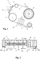
- Figure 1 shows schematically a printing machine in the form of a web-fed inkjet printing machine to which the reference number 1 is assigned as a whole.
- the material web 3 from a printing material, such as paper arrives at a printing unit 40.
- This comprises several inkjet print heads 4 arranged one behind the other along the material web 3, by means of which solvent-based and especially water-based printing inks are applied to the printing material.
- the material web 3 passes from the printing unit 40 via a deflection roller 6 to an infrared dryer system 70.
- This is equipped with several dryer modules 7, which are designed for drying or absorbing the solvent into the material web.
- the further transport path of the material web 3 goes via a tension roller 8, which is equipped with its own tension drive motor and via which the web tension is set, to a take-up roller 9.
- each of the dryer modules is equipped with several infrared radiators - in the exemplary embodiment there are eighteen.
- the dryer modules are arranged in pairs next to and behind one another in the dryer system as seen in the direction of transport.
- the pair of dryer modules 7 arranged next to one another covers the maximum format width of the printing machine 1.
- the dryer modules 7 and the individual infrared radiators can be electrically controlled separately from one another in accordance with the dimensions and color coverage of the printing material.
- the transport speed of the material web 3 is set to 5 m / s. This is a comparatively high speed which is made possible by optimizing the individual processing steps and which in particular requires a high drying rate.
- the drying process required to achieve this requirement and the dryer module 7 used for this purpose is described below with reference to FIG Figures 2 to 4 explained in more detail. Unless in these Figures have the same reference numbers as in Figure 1 are used, then identical or equivalent components and components are referred to, as they are explained in more detail above with reference to the description of the printing press.
- the directional arrows 28 indicate an air flow directed onto the surface of the printing material 3, and the directional arrows 29 an air flow leading away from the printing material 3, as well as an interaction 35 of these air flows with one another Figure 3 is explained.
- the length of the directional arrows 28; 29 symbolizes the increase in the respective flow volumes.
- the surface of the printing material 3 corresponds at the same time to the substrate plane 3a.
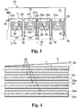
- the in Figure 3 The cross section shown comprises a section of the infrared irradiation chamber 25 along four structurally identical infrared radiator units 30.
- the cross section shows a suction chamber 31, a gas supply chamber 32 and the actual infrared treatment chamber 33.
- the gas supply space 32 is connected to a gas inlet 36 and is composed of a plurality of gas collection spaces 32a, which are fluidically connected to one another via lines 32b.
- Each emitter unit 30 has a gas collecting space 32a.
- Each gas collecting space 32a is provided with a centrally running, elongated opening 37 to the substrate treatment space 33.
- the elongated opening 37 has the shape of a longitudinal slot which extends in the substrate transport direction 5 (perpendicular to the plane of the paper) and which is provided on both longitudinal sides of gas guide elements 38a; 38b is limited.
- the infrared radiator 24 is bell-shaped and are also referred to below collectively as "air guide bell 38".
- the air guide bell 38 ends at a distance of approximately 10 mm in front of the surface of the printing material 3 (the substrate plane 3a).
- the suction space 31 has a gas outlet 34 which is connected to a fan (not shown in the figure).
- Gap-shaped suction channels 39 which run between adjacent IR radiator units 30 and which each end with the air guide elements 38a and 38b in front of the substrate plane 3a, open into the suction space 31.
- the infrared radiators 24 arranged in the substrate treatment room 33 are designed as commercially available twin tube radiators. They consist of an eight-shaped envelope made of quartz glass, which encloses two sub-spaces that are separated from one another by a central web. Their nominal power is 3,500 W. The total radiator length is 70 cm and the outer dimensions of the envelope are 34 x 14 mm.
- the opening 37 for the cooling air in the treatment room 33 and behind it the infrared radiator 24 can be seen.
- the opening width of the elongated opening 37 widens continuously in the transport direction 5.
- the width of the suction channels 39 remains constant in the transport direction 5.
- the transport direction 5 forms an angle of 10 degrees with the longitudinal sides of the suction channels 39 or with the longitudinal axes of the infrared radiators 24 (not visible in the figure).
- the method according to the invention is exemplified below with reference to FIG Figures 1 to 4 explained in more detail:
- the components of the dryer module 7 of Figure 2 have the following functions and effects.
- the front air knife 22 With the help of the guide plate 22a, the front air knife 22 generates an intensive air flow 22b directed towards the printing substrate surface 3a in the transport direction 5, which breaks through the laminar flow boundary layer on the printing substrate 3, creates turbulence and thus promotes evaporation at the beginning of the drying process.
- the front Air Knife 22 in the direction of transport Subsequent suction, some of the air and the components that have been whirled up by means of the front air knife 22 are sucked out of the dryer module 7.
- the rear Air Knife 27, with the help of the guide plate 27a also generates an intensive, Surface 3a directed air flow which breaks through the laminar flow boundary layer on the printing material 3.
- the process gas 27b that has accumulated in front of the air knife 27 is removed by the air exchanger unit 26 upstream in the transport direction.
- a plurality of air curtains 26 a running transversely to the transport direction 5 are generated by means of the air exchanger unit 26.
- a supply air flow 26b directed onto the printing substrate surface 3a is generated for each air curtain 26a and this is drawn off again immediately after it hits the printing substrate via an exhaust air flow 26c.
- the air exchanger unit 26 can take with it the moisture created as a result of the action of the infrared radiation by means of intensive air turbulence and remove it via its integrated suction system, so that undesired components cannot leave the dryer module 7 in a controlled manner.
- the treatment of the printing material 3 in the infrared radiation chamber 25 includes heating by means of infrared radiation with simultaneous exposure to dry air. So that both treatments act as effectively as possible on the printing substrate 3, the cooling air flowing from the gas supply chamber 32 through the elongated opening into the treatment chamber 33 is divided into two process gas flows 28, which are partially guided to the infrared radiator 24 and around its envelope. The infrared heater 24 is cooled and the cooling air is heated at the same time.
- Each air flow 28 directed towards the printing substrate 3 is spatially assigned an exhaust air flow 29 leading away from the printing substrate, in that the directions of the inflowing air flow 28 and the sucked in air flow 29 are directed almost in opposite directions (they enclose an angle of less than 30 degrees with one another in the exemplary embodiment) and in an interaction zone 35 meet, the interaction zone 35 lying on the surface of the printing substrate 3.
- Each of the two air flows 28 therefore meets an exhaust air flow 29 on the printing material surface.
- the resulting interaction between air flow 28 and exhaust air flow 29 leads to gas turbulence in the interaction zone 35, i.e. in the immediate vicinity of the printing substrate surface, which disrupts, reduces or even detaches the fluid dynamic laminar flow boundary layer and, as a result, an improvement in substance transport and in particular the removal of moisture from the printing material 3 can cause.
- An exhaust air flow 29 runs between two air flows 28, one of which is to be assigned to one infrared heater 24 and the other to the adjacent infrared heater 24.
- the interactions (interactions) of the flows 28, 29, 28 with one another generate a particularly intensive gas turbulence in the common strip-shaped interaction area 35 of the substrate surface, which particularly effectively disrupts, reduces or detaches the laminar flow boundary layer on the printing substrate surface, so that rapid drying is achieved.
- the shared use of an exhaust air flow 29 from two adjacent air flows 28 enables a spatially close arrangement of the infrared radiators 24 of the radiator field and thus effective drying with a compact design at the same time.
Landscapes
- Engineering & Computer Science (AREA)
- Mechanical Engineering (AREA)
- General Engineering & Computer Science (AREA)
- Microbiology (AREA)
- Life Sciences & Earth Sciences (AREA)
- Toxicology (AREA)
- Health & Medical Sciences (AREA)
- General Health & Medical Sciences (AREA)
- Chemical & Material Sciences (AREA)
- Combustion & Propulsion (AREA)
- Textile Engineering (AREA)
- Drying Of Solid Materials (AREA)
- Supply, Installation And Extraction Of Printed Sheets Or Plates (AREA)
Claims (15)
- Procédé de séchage au moins partiel d'un substrat (3), comprenant les étapes de procédé :(a) d'émission d'un rayonnement infrarouge en direction d'un substrat déplacé à travers un espace de processus le long d'un trajet de transport et dans une direction de transport au moyen d'une unité émettrice de rayons, qui comprend au moins un émetteur de rayons infrarouges (24),(b) de génération d'au moins deux flux de gaz de processus, dirigés sur le substrat, d'un gaz de processus,(c) de séchage au moins partiel du substrat par l'action d'un rayonnement infrarouge et d'un gaz de processus sur le substrat, et d'évacuation par aspiration de gaz de processus chargé en humidité par l'intermédiaire d'un canal d'évacuation par aspiration hors de l'espace de processus en formant un flux d'air sortant s'éloignant du substrat,caractérisé en ce que les au moins deux flux de gaz de processus (28) sont guidés à l'émetteur de rayons infrarouges (24) avant qu'ils n'agissent sur le substrat, etqu'un flux d'air sortant s'éloignant du substrat est associé spatialement et est adjacent à chaque flux de gaz de processus dirigé sur le substrat.
- Procédé selon la revendication 1, caractérisé en ce qu'un émetteur de rayons infrarouges présentant un axe longitudinal est utilisé, et que l'émetteur de rayons infrarouges est balayé de part et autre de son axe longitudinal par respectivement un des deux flux de gaz de processus.
- Procédé selon la revendication 1 ou 2, caractérisé en ce que les au moins deux flux de gaz de processus agissent en forme de bande sur le substrat à sécher, et que respectivement un flux d'air sortant en forme de bande est associé spatialement de manière préférée aux flux de gaz de processus en forme de bande.
- Procédé selon l'une quelconque des revendications précédentes, caractérisé en ce qu'est employée, aux fins d'une exposition à un rayonnement infrarouge à plat du substrat, une unité émettrice de rayons, qui comprend une pluralité d'émetteurs de rayons infrarouges qui présentent des axes longitudinaux s'étendant respectivement de manière parallèle les uns par rapport aux autres, dans lequel un flux de gaz de processus dirigé sur le substrat est guidé de manière préférée autour de chacun des axes longitudinaux d'émetteur de rayons infrarouges, dans lequel des flux de gaz de processus adjacents d'émetteurs de rayons infrarouges adjacents sont associés spatialement à un flux d'air sortant commun.
- Procédé selon la revendication 4, caractérisé en ce que les axes longitudinaux d'émetteurs de rayons infrarouges s'étendent dans la direction de transport de substrat ou forment avec la direction de transport de substrat un angle inférieur à 30 degrés.
- Procédé selon l'une quelconque des revendications 4 ou 5, caractérisé en ce que l'espace de processus est réalisé dans un module sécheur à rayons infrarouges, qui présente, vu dans la direction de transport du substrat, une combinaison de composants suivants : une lame d'air avant (Air-Knife), un espace d'exposition à un rayonnement équipé de plusieurs émetteurs de rayons infrarouges disposés de manière parallèle les uns par rapport aux autres, une unité d'échange d'air avec une évacuation par aspiration intégrée et une lame d'air arrière, dans lequel une évacuation par aspiration suit de manière préférée la lame d'air avant dans la direction de transport.
- Procédé selon l'une quelconque des revendications 4 à 6, caractérisé en ce qu'est imprimée sur le flux de gaz de processus une caractéristique de volume, qui augmente dans la direction de transport de substrat au moins sur une longueur partielle de la longueur d'émetteur de rayons infrarouges.
- Procédé selon l'une quelconque des revendications précédentes, caractérisé en ce que le volume de gaz introduit dans le module sécheur Vin est réglé au moyen d'une commande de quantité de gaz de processus de manière à être inférieur au volume de gaz évacué par aspiration hors du module sécheur Vout.
- Module sécheur à rayons infrarouges pour sécher un substrat déplacé dans un plan de substrat et dans une direction de transport à travers un espace de processus, comprenant(a) une unité émettrice de rayons, qui comprend au moins un émetteur de rayons infrarouges (24) présentant un axe longitudinal pour l'émission d'un rayonnement infrarouge sur le plan de substrat,(b) une unité d'amenée de gaz de processus avec un espace de collecte de gaz de processus, qui présente au moins une ouverture d'entrée pour l'introduction de gaz de processus (27b) depuis l'espace de collecte de gaz de processus dans l'espace de processus, dans lequel un élément d'acheminement de gaz qui s'étend en direction du plan de substrat jouxte l'ouverture d'entrée,(c) une unité d'air sortant avec au moins un canal d'évacuation par aspiration pour l'évacuation de gaz de processus chargé en humidité hors de l'espace de processus,
caractérisé en ce que l'émetteur de rayons infrarouges est disposé par rapport à l'ouverture d'entrée de telle sorte qu'il forme avec l'élément d'acheminement de gaz de part et d'autre de son axe longitudinal respectivement un canal d'entrée pour le gaz de processus, et dans lequel au moins un canal d'évacuation par aspiration de gaz de processus est adjacent à chaque canal d'entrée de gaz de processus. - Module sécheur selon la revendication 9, caractérisé en ce que l'élément d'acheminement de gaz et le canal d'évacuation par aspiration ont une section de paroi commune, qui se termine à une distance par rapport au plan de substrat.
- Module sécheur selon la revendication 9 ou 10, caractérisé en ce que l'unité émettrice de rayons comprend une pluralité d'émetteurs de rayons infrarouges, qui présentent des axes longitudinaux s'étendant respectivement de manière parallèle les uns par rapport aux autres, dans lequel un canal d'évacuation par aspiration commun est disposé de manière préférée entre des émetteurs de rayons infrarouges adjacents.
- Module sécheur selon la revendication 11, caractérisé en ce que les axes longitudinaux d'émetteurs de rayons infrarouges s'étendent dans la direction de transport de substrat ou forment avec la direction de transport de substrat un angle inférieur à 30 degrés.
- Module sécheur selon l'une quelconque des revendications 11 ou 12, caractérisé en ce que l'espace de processus présente des composants suivants vus dans la direction de transport : une lame d'air avant (Air-Knife), un espace d'exposition à un rayonnement équipé de plusieurs émetteurs de rayons infrarouges disposés de manière parallèle les uns par rapport aux autres, une unité d'échange d'air avec une évacuation par aspiration intégrée et une lame d'air arrière, dans lequel une évacuation par aspiration suit de manière préférée la lame d'air avant dans la direction de transport.
- Module sécheur selon l'une quelconque des revendications 11 à 13, caractérisé en ce qu'est imprimée sur le flux de gaz de processus une caractéristique de volume, qui augmente dans la direction de transport de substrat au moins sur une longueur partielle de la longueur d'émetteur de rayons infrarouges.
- Système sécheur pour sécher un substrat déplacé dans un plan de substrat et dans une direction de transport à travers un espace de processus, qui contient plusieurs modules sécheurs selon l'une quelconque des revendications 11 à 14, qui sont disposés côte à côte et/ou les uns derrière les autres dans la direction de transport.
Applications Claiming Priority (2)
| Application Number | Priority Date | Filing Date | Title |
|---|---|---|---|
| DE102017129017.6A DE102017129017A1 (de) | 2017-12-06 | 2017-12-06 | Verfahren zum Trocknen eines Substrats, Trocknermodul zur Durchführung des Verfahrens sowie Trocknersystem |
| PCT/EP2018/083303 WO2019110484A1 (fr) | 2017-12-06 | 2018-12-03 | Procédé pour le séchage d'un substrat, module de séchage pour la mise en œuvre du procédé ainsi que système de séchage |
Publications (2)
| Publication Number | Publication Date |
|---|---|
| EP3720716A1 EP3720716A1 (fr) | 2020-10-14 |
| EP3720716B1 true EP3720716B1 (fr) | 2021-09-22 |
Family
ID=64650377
Family Applications (1)
| Application Number | Title | Priority Date | Filing Date |
|---|---|---|---|
| EP18815146.8A Active EP3720716B1 (fr) | 2017-12-06 | 2018-12-03 | Procédé pour le séchage d'un substrat, module de séchage pour la mise en oeuvre du procédé ainsi que système de séchage |
Country Status (6)
| Country | Link |
|---|---|
| US (1) | US20200300542A1 (fr) |
| EP (1) | EP3720716B1 (fr) |
| JP (1) | JP7114712B2 (fr) |
| CN (1) | CN111465501B (fr) |
| DE (1) | DE102017129017A1 (fr) |
| WO (1) | WO2019110484A1 (fr) |
Families Citing this family (3)
| Publication number | Priority date | Publication date | Assignee | Title |
|---|---|---|---|---|
| DE102019126701A1 (de) * | 2019-10-02 | 2021-04-08 | Heraeus Noblelight Gmbh | Infrarot-Trocknermodul und Trocknersystem |
| DE202020002017U1 (de) | 2020-05-08 | 2020-05-25 | Gunther Ackermann | Vorrichtung zur Bestrahlung eines Substrates |
| DE102022124575A1 (de) | 2022-09-23 | 2024-03-28 | Duo Technik Gmbh | Vorrichtung zum Trocknen von Flächengebilden |
Family Cites Families (20)
| Publication number | Priority date | Publication date | Assignee | Title |
|---|---|---|---|---|
| IT965804B (it) * | 1972-05-10 | 1974-02-11 | Minnesota Mining & Mfg | Procedimento e dispositivo per la asciugatura rapida di pellicole fotografiche |
| SE468287B (sv) * | 1991-04-22 | 1992-12-07 | Infraroedteknik Ab | Saett resp anordning foer behandling av en kontinuerlig materialbana |
| JP2002052850A (ja) | 2000-08-14 | 2002-02-19 | Toppan Printing Co Ltd | 環境配慮型高光沢印刷物の製造方法 |
| JP4656358B2 (ja) | 2001-02-15 | 2011-03-23 | 上垣 健男 | 乾燥装置 |
| JP2003094605A (ja) | 2001-09-26 | 2003-04-03 | Toppan Printing Co Ltd | 乾燥器 |
| US6655040B2 (en) * | 2002-01-04 | 2003-12-02 | The Diagnostics Group, Inc. | Combination ultraviolet curing and infrared drying system |
| CH695677A5 (fr) * | 2002-10-01 | 2006-07-31 | Bobst Sa | Dispositif pour le séchage d'une matière imprimée. |
| CN101375121B (zh) * | 2006-01-25 | 2010-12-01 | 贝卡尔特股份有限公司 | 干燥器设备的对流系统 |
| JP2007320183A (ja) | 2006-06-01 | 2007-12-13 | Daikin Ind Ltd | 印刷機の排気システム |
| JP2009243701A (ja) | 2008-03-28 | 2009-10-22 | Fujifilm Corp | 乾燥装置及び画像形成装置 |
| EP2437941B1 (fr) * | 2009-06-05 | 2015-03-18 | Megtec Systems, Inc. | Methode pour barre flottante infrarouge |
| JP4967013B2 (ja) * | 2009-12-11 | 2012-07-04 | 東京エレクトロン株式会社 | 基板処理装置、基板処理方法及びこの基板処理方法を実行させるためのプログラムを記録した記録媒体 |
| DE102010046756A1 (de) | 2010-09-28 | 2012-03-29 | Eltosch Torsten Schmidt Gmbh | Trocknermodul für Druckmaschinen |
| JP5421934B2 (ja) | 2011-01-13 | 2014-02-19 | 東京エレクトロン株式会社 | 電極製造装置、電極製造方法 |
| CN102632700A (zh) * | 2012-04-18 | 2012-08-15 | 广东新优威印刷装备科技有限公司 | 印刷机 |
| FI124272B (fi) * | 2012-06-06 | 2014-05-30 | Ccm Power Oy | Kuivuri ja menetelmä materiaalin kuivaamiseksi |
| EP3003578A4 (fr) * | 2013-05-31 | 2018-02-21 | Rosenberg, Joe, I.v. | Procédé et appareil de conversion d'une presse d'impression à l'humide sans sécheur en une presse d'impression à l'humide avec sécheur et sans sécheur hybride |
| WO2017194335A2 (fr) * | 2016-05-09 | 2017-11-16 | Intrinsic Id B.V. | Dispositif de programmation conçu pour obtenir et stocker une chaîne de bits aléatoires dans un dispositif mémoire |
| US10308010B2 (en) * | 2017-02-08 | 2019-06-04 | Ricoh Company, Ltd. | Infrared-heated air knives for dryers |
| US10723119B2 (en) * | 2017-03-17 | 2020-07-28 | Ricoh Company, Ltd. | Dryer, printer, and treatment liquid applicator |
-
2017
- 2017-12-06 DE DE102017129017.6A patent/DE102017129017A1/de not_active Ceased
-
2018
- 2018-12-03 CN CN201880079295.2A patent/CN111465501B/zh active Active
- 2018-12-03 WO PCT/EP2018/083303 patent/WO2019110484A1/fr unknown
- 2018-12-03 US US16/766,857 patent/US20200300542A1/en active Pending
- 2018-12-03 JP JP2020531016A patent/JP7114712B2/ja active Active
- 2018-12-03 EP EP18815146.8A patent/EP3720716B1/fr active Active
Also Published As
| Publication number | Publication date |
|---|---|
| EP3720716A1 (fr) | 2020-10-14 |
| JP7114712B2 (ja) | 2022-08-08 |
| DE102017129017A1 (de) | 2019-06-06 |
| CN111465501A (zh) | 2020-07-28 |
| US20200300542A1 (en) | 2020-09-24 |
| CN111465501B (zh) | 2022-08-12 |
| JP2021505837A (ja) | 2021-02-18 |
| WO2019110484A1 (fr) | 2019-06-13 |
Similar Documents
| Publication | Publication Date | Title |
|---|---|---|
| EP3720716B1 (fr) | Procédé pour le séchage d'un substrat, module de séchage pour la mise en oeuvre du procédé ainsi que système de séchage | |
| EP1058805B2 (fr) | Procede et dispositif pour le sechage d'un produit defilant rapidement, notamment pour le sechage d'encre d'imprimerie | |
| EP3258200B1 (fr) | Dispositif de traitement d'un produit, en particulier destiné à sécher un produit de préférence sous forme de bande | |
| EP3788313B1 (fr) | Procédé de séchage d'un substrat, module de séchage à air et système de séchage | |
| DE102011009693A1 (de) | Kühlmodul und Vorrichtung zum thermischen Behandeln von Substraten | |
| WO2020058163A1 (fr) | Unité de chauffage infrarouge pour sécher des encres ou des vernis dans une machine d'impression, et module à radiateur infrarouge pour machine d'impression | |
| WO2010022857A1 (fr) | Dispositif et procédé pour l’impression et le séchage de films en matière plastique | |
| WO2010066224A2 (fr) | Procédé et dispositif pour appliquer sans contact un vernis d'impression uv sur un support d'impression | |
| EP3781404A1 (fr) | Machine de traitement équipée d'un sécheur à rayons et procédé de fonctionnement de ce sécheur | |
| WO2020078606A1 (fr) | Procédé d'impression d'une surface d'un substrat non absorbant au moyen d'une encre à appliquer par un dispositif d'impression à jet d'encre, et imprimante numérique permettant la mise en œuvre dudit procédé | |
| WO2021214128A1 (fr) | Procédé de séchage d'un produit exposé à un rayonnement et dispositif d'exposition à un rayonnement infrarouge pour mettre en œuvre ledit procédé | |
| DE102007035989A1 (de) | System zum Trocknen eines Substrats | |
| DE102009054865B4 (de) | Trockner | |
| DE19934487A1 (de) | Durchlauftrockner für Platten oder Bahnen | |
| DE102013112172B3 (de) | Trockner für Warenbahnen | |
| DE102014115866A1 (de) | Einrichtung zur Farbwerksbelüftung | |
| WO2003020522A1 (fr) | Système de séchage par rayonnement | |
| EP3569418B1 (fr) | Procédé de fonctionnement d'une machine d'impression | |
| WO2004035313A1 (fr) | Secheur pour bande de matiere | |
| EP2589909A2 (fr) | Dispositif de chauffage ou de séchage de matériaux allongés | |
| DE19926749A1 (de) | Farbwerk für eine Druckmaschine | |
| DE102004060059A1 (de) | Rotationsdruckmaschine mit integrierter Lackiereinrichtung | |
| DE102016201480B4 (de) | Vorrichtung und Verfahren zum Trocknen eines Bandmaterials einer Druckmaschine | |
| DE10062618A1 (de) | Durchlauftrockner für Platten oder Bahnen | |
| DE102022124767A1 (de) | Vorrichtung zum Trocknen von Bedruckstoff |
Legal Events
| Date | Code | Title | Description |
|---|---|---|---|
| STAA | Information on the status of an ep patent application or granted ep patent |
Free format text: STATUS: UNKNOWN |
|
| STAA | Information on the status of an ep patent application or granted ep patent |
Free format text: STATUS: THE INTERNATIONAL PUBLICATION HAS BEEN MADE |
|
| PUAI | Public reference made under article 153(3) epc to a published international application that has entered the european phase |
Free format text: ORIGINAL CODE: 0009012 |
|
| STAA | Information on the status of an ep patent application or granted ep patent |
Free format text: STATUS: REQUEST FOR EXAMINATION WAS MADE |
|
| 17P | Request for examination filed |
Effective date: 20200604 |
|
| AK | Designated contracting states |
Kind code of ref document: A1 Designated state(s): AL AT BE BG CH CY CZ DE DK EE ES FI FR GB GR HR HU IE IS IT LI LT LU LV MC MK MT NL NO PL PT RO RS SE SI SK SM TR |
|
| AX | Request for extension of the european patent |
Extension state: BA ME |
|
| DAV | Request for validation of the european patent (deleted) | ||
| DAX | Request for extension of the european patent (deleted) | ||
| GRAP | Despatch of communication of intention to grant a patent |
Free format text: ORIGINAL CODE: EPIDOSNIGR1 |
|
| STAA | Information on the status of an ep patent application or granted ep patent |
Free format text: STATUS: GRANT OF PATENT IS INTENDED |
|
| INTG | Intention to grant announced |
Effective date: 20210512 |
|
| GRAS | Grant fee paid |
Free format text: ORIGINAL CODE: EPIDOSNIGR3 |
|
| GRAA | (expected) grant |
Free format text: ORIGINAL CODE: 0009210 |
|
| STAA | Information on the status of an ep patent application or granted ep patent |
Free format text: STATUS: THE PATENT HAS BEEN GRANTED |
|
| AK | Designated contracting states |
Kind code of ref document: B1 Designated state(s): AL AT BE BG CH CY CZ DE DK EE ES FI FR GB GR HR HU IE IS IT LI LT LU LV MC MK MT NL NO PL PT RO RS SE SI SK SM TR |
|
| REG | Reference to a national code |
Ref country code: GB Ref legal event code: FG4D Free format text: NOT ENGLISH |
|
| REG | Reference to a national code |
Ref country code: IE Ref legal event code: FG4D Free format text: LANGUAGE OF EP DOCUMENT: GERMAN |
|
| REG | Reference to a national code |
Ref country code: DE Ref legal event code: R096 Ref document number: 502018007205 Country of ref document: DE |
|
| REG | Reference to a national code |
Ref country code: CH Ref legal event code: EP Ref country code: AT Ref legal event code: REF Ref document number: 1432007 Country of ref document: AT Kind code of ref document: T Effective date: 20211015 |
|
| REG | Reference to a national code |
Ref country code: LT Ref legal event code: MG9D |
|
| REG | Reference to a national code |
Ref country code: NL Ref legal event code: MP Effective date: 20210922 |
|
| PG25 | Lapsed in a contracting state [announced via postgrant information from national office to epo] |
Ref country code: HR Free format text: LAPSE BECAUSE OF FAILURE TO SUBMIT A TRANSLATION OF THE DESCRIPTION OR TO PAY THE FEE WITHIN THE PRESCRIBED TIME-LIMIT Effective date: 20210922 Ref country code: NO Free format text: LAPSE BECAUSE OF FAILURE TO SUBMIT A TRANSLATION OF THE DESCRIPTION OR TO PAY THE FEE WITHIN THE PRESCRIBED TIME-LIMIT Effective date: 20211222 Ref country code: LT Free format text: LAPSE BECAUSE OF FAILURE TO SUBMIT A TRANSLATION OF THE DESCRIPTION OR TO PAY THE FEE WITHIN THE PRESCRIBED TIME-LIMIT Effective date: 20210922 Ref country code: BG Free format text: LAPSE BECAUSE OF FAILURE TO SUBMIT A TRANSLATION OF THE DESCRIPTION OR TO PAY THE FEE WITHIN THE PRESCRIBED TIME-LIMIT Effective date: 20211222 Ref country code: FI Free format text: LAPSE BECAUSE OF FAILURE TO SUBMIT A TRANSLATION OF THE DESCRIPTION OR TO PAY THE FEE WITHIN THE PRESCRIBED TIME-LIMIT Effective date: 20210922 Ref country code: RS Free format text: LAPSE BECAUSE OF FAILURE TO SUBMIT A TRANSLATION OF THE DESCRIPTION OR TO PAY THE FEE WITHIN THE PRESCRIBED TIME-LIMIT Effective date: 20210922 Ref country code: SE Free format text: LAPSE BECAUSE OF FAILURE TO SUBMIT A TRANSLATION OF THE DESCRIPTION OR TO PAY THE FEE WITHIN THE PRESCRIBED TIME-LIMIT Effective date: 20210922 |
|
| PG25 | Lapsed in a contracting state [announced via postgrant information from national office to epo] |
Ref country code: LV Free format text: LAPSE BECAUSE OF FAILURE TO SUBMIT A TRANSLATION OF THE DESCRIPTION OR TO PAY THE FEE WITHIN THE PRESCRIBED TIME-LIMIT Effective date: 20210922 Ref country code: GR Free format text: LAPSE BECAUSE OF FAILURE TO SUBMIT A TRANSLATION OF THE DESCRIPTION OR TO PAY THE FEE WITHIN THE PRESCRIBED TIME-LIMIT Effective date: 20211223 |
|
| PG25 | Lapsed in a contracting state [announced via postgrant information from national office to epo] |
Ref country code: IS Free format text: LAPSE BECAUSE OF FAILURE TO SUBMIT A TRANSLATION OF THE DESCRIPTION OR TO PAY THE FEE WITHIN THE PRESCRIBED TIME-LIMIT Effective date: 20220122 Ref country code: SK Free format text: LAPSE BECAUSE OF FAILURE TO SUBMIT A TRANSLATION OF THE DESCRIPTION OR TO PAY THE FEE WITHIN THE PRESCRIBED TIME-LIMIT Effective date: 20210922 Ref country code: RO Free format text: LAPSE BECAUSE OF FAILURE TO SUBMIT A TRANSLATION OF THE DESCRIPTION OR TO PAY THE FEE WITHIN THE PRESCRIBED TIME-LIMIT Effective date: 20210922 Ref country code: PT Free format text: LAPSE BECAUSE OF FAILURE TO SUBMIT A TRANSLATION OF THE DESCRIPTION OR TO PAY THE FEE WITHIN THE PRESCRIBED TIME-LIMIT Effective date: 20220124 Ref country code: PL Free format text: LAPSE BECAUSE OF FAILURE TO SUBMIT A TRANSLATION OF THE DESCRIPTION OR TO PAY THE FEE WITHIN THE PRESCRIBED TIME-LIMIT Effective date: 20210922 Ref country code: NL Free format text: LAPSE BECAUSE OF FAILURE TO SUBMIT A TRANSLATION OF THE DESCRIPTION OR TO PAY THE FEE WITHIN THE PRESCRIBED TIME-LIMIT Effective date: 20210922 Ref country code: ES Free format text: LAPSE BECAUSE OF FAILURE TO SUBMIT A TRANSLATION OF THE DESCRIPTION OR TO PAY THE FEE WITHIN THE PRESCRIBED TIME-LIMIT Effective date: 20210922 Ref country code: EE Free format text: LAPSE BECAUSE OF FAILURE TO SUBMIT A TRANSLATION OF THE DESCRIPTION OR TO PAY THE FEE WITHIN THE PRESCRIBED TIME-LIMIT Effective date: 20210922 Ref country code: CZ Free format text: LAPSE BECAUSE OF FAILURE TO SUBMIT A TRANSLATION OF THE DESCRIPTION OR TO PAY THE FEE WITHIN THE PRESCRIBED TIME-LIMIT Effective date: 20210922 Ref country code: AL Free format text: LAPSE BECAUSE OF FAILURE TO SUBMIT A TRANSLATION OF THE DESCRIPTION OR TO PAY THE FEE WITHIN THE PRESCRIBED TIME-LIMIT Effective date: 20210922 |
|
| REG | Reference to a national code |
Ref country code: DE Ref legal event code: R097 Ref document number: 502018007205 Country of ref document: DE |
|
| PG25 | Lapsed in a contracting state [announced via postgrant information from national office to epo] |
Ref country code: MC Free format text: LAPSE BECAUSE OF FAILURE TO SUBMIT A TRANSLATION OF THE DESCRIPTION OR TO PAY THE FEE WITHIN THE PRESCRIBED TIME-LIMIT Effective date: 20210922 Ref country code: DK Free format text: LAPSE BECAUSE OF FAILURE TO SUBMIT A TRANSLATION OF THE DESCRIPTION OR TO PAY THE FEE WITHIN THE PRESCRIBED TIME-LIMIT Effective date: 20210922 |
|
| PLBE | No opposition filed within time limit |
Free format text: ORIGINAL CODE: 0009261 |
|
| REG | Reference to a national code |
Ref country code: CH Ref legal event code: PL |
|
| STAA | Information on the status of an ep patent application or granted ep patent |
Free format text: STATUS: NO OPPOSITION FILED WITHIN TIME LIMIT |
|
| 26N | No opposition filed |
Effective date: 20220623 |
|
| REG | Reference to a national code |
Ref country code: BE Ref legal event code: MM Effective date: 20211231 |
|
| PG25 | Lapsed in a contracting state [announced via postgrant information from national office to epo] |
Ref country code: LU Free format text: LAPSE BECAUSE OF NON-PAYMENT OF DUE FEES Effective date: 20211203 Ref country code: IE Free format text: LAPSE BECAUSE OF NON-PAYMENT OF DUE FEES Effective date: 20211203 |
|
| PG25 | Lapsed in a contracting state [announced via postgrant information from national office to epo] |
Ref country code: SI Free format text: LAPSE BECAUSE OF FAILURE TO SUBMIT A TRANSLATION OF THE DESCRIPTION OR TO PAY THE FEE WITHIN THE PRESCRIBED TIME-LIMIT Effective date: 20210922 Ref country code: BE Free format text: LAPSE BECAUSE OF NON-PAYMENT OF DUE FEES Effective date: 20211231 |
|
| PG25 | Lapsed in a contracting state [announced via postgrant information from national office to epo] |
Ref country code: LI Free format text: LAPSE BECAUSE OF NON-PAYMENT OF DUE FEES Effective date: 20211231 Ref country code: CH Free format text: LAPSE BECAUSE OF NON-PAYMENT OF DUE FEES Effective date: 20211231 |
|
| PG25 | Lapsed in a contracting state [announced via postgrant information from national office to epo] |
Ref country code: IT Free format text: LAPSE BECAUSE OF FAILURE TO SUBMIT A TRANSLATION OF THE DESCRIPTION OR TO PAY THE FEE WITHIN THE PRESCRIBED TIME-LIMIT Effective date: 20210922 |
|
| PG25 | Lapsed in a contracting state [announced via postgrant information from national office to epo] |
Ref country code: CY Free format text: LAPSE BECAUSE OF FAILURE TO SUBMIT A TRANSLATION OF THE DESCRIPTION OR TO PAY THE FEE WITHIN THE PRESCRIBED TIME-LIMIT Effective date: 20210922 |
|
| P01 | Opt-out of the competence of the unified patent court (upc) registered |
Effective date: 20230530 |
|
| PG25 | Lapsed in a contracting state [announced via postgrant information from national office to epo] |
Ref country code: SM Free format text: LAPSE BECAUSE OF FAILURE TO SUBMIT A TRANSLATION OF THE DESCRIPTION OR TO PAY THE FEE WITHIN THE PRESCRIBED TIME-LIMIT Effective date: 20210922 Ref country code: HU Free format text: LAPSE BECAUSE OF FAILURE TO SUBMIT A TRANSLATION OF THE DESCRIPTION OR TO PAY THE FEE WITHIN THE PRESCRIBED TIME-LIMIT; INVALID AB INITIO Effective date: 20181203 |
|
| PGFP | Annual fee paid to national office [announced via postgrant information from national office to epo] |
Ref country code: GB Payment date: 20231220 Year of fee payment: 6 |
|
| REG | Reference to a national code |
Ref country code: DE Ref legal event code: R082 Ref document number: 502018007205 Country of ref document: DE Representative=s name: MEWBURN ELLIS LLP, DE |
|
| PGFP | Annual fee paid to national office [announced via postgrant information from national office to epo] |
Ref country code: FR Payment date: 20231222 Year of fee payment: 6 Ref country code: DE Payment date: 20231214 Year of fee payment: 6 |
|
| PG25 | Lapsed in a contracting state [announced via postgrant information from national office to epo] |
Ref country code: MK Free format text: LAPSE BECAUSE OF FAILURE TO SUBMIT A TRANSLATION OF THE DESCRIPTION OR TO PAY THE FEE WITHIN THE PRESCRIBED TIME-LIMIT Effective date: 20210922 |