EP3716232B1 - Geldhandhabungsvorrichtung und verfahren zur steuerung der geldhandhabungsvorrichtung - Google Patents
Geldhandhabungsvorrichtung und verfahren zur steuerung der geldhandhabungsvorrichtung Download PDFInfo
- Publication number
- EP3716232B1 EP3716232B1 EP20163828.5A EP20163828A EP3716232B1 EP 3716232 B1 EP3716232 B1 EP 3716232B1 EP 20163828 A EP20163828 A EP 20163828A EP 3716232 B1 EP3716232 B1 EP 3716232B1
- Authority
- EP
- European Patent Office
- Prior art keywords
- unit
- processing
- sensor
- identification information
- correction value
- Prior art date
- Legal status (The legal status is an assumption and is not a legal conclusion. Google has not performed a legal analysis and makes no representation as to the accuracy of the status listed.)
- Active
Links
Images



Classifications
-
- G—PHYSICS
- G07—CHECKING-DEVICES
- G07D—HANDLING OF COINS OR VALUABLE PAPERS, e.g. TESTING, SORTING BY DENOMINATIONS, COUNTING, DISPENSING, CHANGING OR DEPOSITING
- G07D11/00—Devices accepting coins; Devices accepting, dispensing, sorting or counting valuable papers
- G07D11/40—Device architecture, e.g. modular construction
-
- G—PHYSICS
- G07—CHECKING-DEVICES
- G07D—HANDLING OF COINS OR VALUABLE PAPERS, e.g. TESTING, SORTING BY DENOMINATIONS, COUNTING, DISPENSING, CHANGING OR DEPOSITING
- G07D11/00—Devices accepting coins; Devices accepting, dispensing, sorting or counting valuable papers
- G07D11/20—Controlling or monitoring the operation of devices; Data handling
- G07D11/22—Means for sensing or detection
- G07D11/225—Means for sensing or detection for detecting or indicating tampering
-
- G—PHYSICS
- G07—CHECKING-DEVICES
- G07D—HANDLING OF COINS OR VALUABLE PAPERS, e.g. TESTING, SORTING BY DENOMINATIONS, COUNTING, DISPENSING, CHANGING OR DEPOSITING
- G07D11/00—Devices accepting coins; Devices accepting, dispensing, sorting or counting valuable papers
- G07D11/20—Controlling or monitoring the operation of devices; Data handling
- G07D11/28—Setting of parameters; Software updates
-
- G—PHYSICS
- G07—CHECKING-DEVICES
- G07D—HANDLING OF COINS OR VALUABLE PAPERS, e.g. TESTING, SORTING BY DENOMINATIONS, COUNTING, DISPENSING, CHANGING OR DEPOSITING
- G07D7/00—Testing specially adapted to determine the identity or genuineness of valuable papers or for segregating those which are unacceptable, e.g. banknotes that are alien to a currency
- G07D7/04—Testing magnetic properties of the materials thereof, e.g. by detection of magnetic imprint
-
- G—PHYSICS
- G07—CHECKING-DEVICES
- G07D—HANDLING OF COINS OR VALUABLE PAPERS, e.g. TESTING, SORTING BY DENOMINATIONS, COUNTING, DISPENSING, CHANGING OR DEPOSITING
- G07D7/00—Testing specially adapted to determine the identity or genuineness of valuable papers or for segregating those which are unacceptable, e.g. banknotes that are alien to a currency
- G07D7/06—Testing specially adapted to determine the identity or genuineness of valuable papers or for segregating those which are unacceptable, e.g. banknotes that are alien to a currency using wave or particle radiation
- G07D7/12—Visible light, infrared or ultraviolet radiation
-
- G—PHYSICS
- G07—CHECKING-DEVICES
- G07D—HANDLING OF COINS OR VALUABLE PAPERS, e.g. TESTING, SORTING BY DENOMINATIONS, COUNTING, DISPENSING, CHANGING OR DEPOSITING
- G07D7/00—Testing specially adapted to determine the identity or genuineness of valuable papers or for segregating those which are unacceptable, e.g. banknotes that are alien to a currency
- G07D7/16—Testing the dimensions
- G07D7/164—Thickness
Definitions
- the present invention relates to money handling devices and methods for controlling money handling devices.
- the present invention specifically relates to a money handling device including a sensor unit configured to collect data for recognition from money and a method for controlling the same.
- JP 2013-232223 A discloses a system for preventing use of imitations by checking whether a part (e.g., a filter) to be mounted on a machine in treatment is a genuine part.
- a part e.g., a filter
- JP 3266002 B and JP 4690532 B each disclose a recognition unit that is used for a device such as a copier or a printer including a replaceable part (e.g., an ink cartridge) and that recognizes whether a replacement part is genuine.
- a recognition unit that is used for a device such as a copier or a printer including a replaceable part (e.g., an ink cartridge) and that recognizes whether a replacement part is genuine.
- JP 4707373 B discloses an electronic device such as a copier or a printer including a replaceable part (e.g., an ink cartridge). This electronic device can prevent a reduction in reliability of the device due to malfunctions of third-party products.
- Document US 2017/249807 A1 discloses a medium transaction device including: a conveyance section for a medium; a customer interface attachment point; a classification section attachment point; a storage section attachment point; and a controller that controls transaction processing of the medium with the user.
- Document WO 2018/003915 A1 provides a paper sheet identification device and a paper sheet identification method that are able to deal with a greater variety of requests.
- Money handling devices including sensor units require precise adjustment because even a slight machine difference (individual difference) in performance between the sensor units has a significant influence on the recognition results by the money recognition unit.
- repair, replacement, or conversion of a sensor unit by a route other than the regular route in other words, by an uncertified worker, with an uncertified tool, and/or through an uncertified step may cause a recognition failure by the money recognition unit, causing processing errors in money handling devices.
- money handling devices may cause many rejections.
- an object of the present invention is to provide a money handling device having excellent quality and small variation in quality due to machine difference, and a method for controlling a money handling device capable of ensuring excellent quality and reducing a variation in quality due to machine difference.
- One aspect of the present invention is directed to a money handling device as claimed in claim 1.
- the correction value calculation/storage processing unit executes the storage processing after the correction value calculation processing.
- the correction value calculation/storage processing unit is configured to execute the storage processing when the correction value is calculated in the correction value calculation processing.
- the correction value calculation/storage processing unit executes the storage processing during the correction value calculation processing.
- the correction value calculation/storage processing unit stores the correction value into at least one selected from the sensor storage unit and the device storage unit.
- Another aspect of the present invention is directed to a method for controlling a money handling device as claimed in claim 6.
- the money handling device of the present invention is capable of having excellent quality and small variation in quality due to machine difference.
- the method for controlling a money handling device of the present invention can provide a money handling device having excellent quality and small variation in quality due to machine difference.
- a non-claimed example and preferred embodiments of the money handling device and the method for controlling a money handling device of the present invention are described hereinbelow with reference to the drawings.
- the present invention is described with those directed to banknotes, i.e., a banknote handling device and a method for controlling a banknote handling device, taken as examples.
- the money as used herein encompasses coins and sheets such as banknotes.
- FIG. 1 With reference to Fig. 1 , the structure of a banknote handling device of a non-claimed example is described.
- a banknote handling device 200 of the non-claimed example may have a structure as illustrated in Figs. 1(a) and 1(b) .
- the banknote handling device 200 illustrated in Figs. 1(a) and 1(b) includes a hopper 210 that can hold multiple banknotes, a feeding unit 211 that can feed out the banknotes held on the hopper 210 one by one, a transport path 212 on which the banknotes fed out of the feeding unit 211 are transported, a banknote recognition unit 100 that executes recognition processing on the banknotes, a stacking unit 213 that stacks banknotes recognized as normal by the banknote recognition unit 100, a rejection unit 214 that stacks abnormal banknotes failing to satisfy predetermined conditions, a display 215 that displays data such as information sent to the banknote handling device 200 and processing results, and a transport unit that transports the banknotes one by one along the transport path 212.
- the transport unit includes multiple transport means such as rollers and a driving unit, such as a motor, that drives the transport means.
- the banknote handling device 200 further includes transmissive or reflective optical sensors at the respective positions indicated by the triangles in the figure to detect the transport states of the banknotes in the device. The detection results from these optical sensors may be used to estimate the shape and degree of skewing of each banknote.
- Using the banknote recognition unit 100 provided within the banknote handling device 200 enables successive handling of multiple banknotes held on the hopper 210, returning of banknotes each determined as a counterfeit note, unfit note, or suspect note to the rejection unit 214, and resulting sorting of the banknotes.
- the contents of the recognition processing by the banknote recognition unit 100 include a variety of functions such as, but not limited to, recognition of the denominations, determination of the authenticity and fitness of banknotes, determination of the orientation and face-up or face-down state of banknotes, acquisition of the external shape information and passing site information of banknotes, and reading of symbols such as figures and characters printed on banknotes.
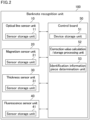
- the banknote recognition unit 100 includes, as sensor units that collect data for recognition processing from a banknote, an optical line sensor unit 10 that emits multiple types of light such as infrared light and visible light to acquire optical data (optical properties) of a banknote, a magnetism sensor unit 20 that acquires magnetic data (magnetism) of the banknote, a thickness sensor unit 30 that acquires thickness data of the banknote, and a fluorescence sensor unit 40 that emits ultraviolet light to acquire fluorescence data of the banknote.
- the sensor units 10, 20, 30, and 40 are removably attached to the banknote recognition unit 100 and can be replaced as appropriate.
- the banknote recognition unit 100 executes processing such as banknote recognition processing based on the data acquired by the sensor units 10, 20, 30, and 40.
- processing such as banknote recognition processing based on the data acquired by the sensor units 10, 20, 30, and 40.
- an optical image of the banknote is generated from the optical data acquired by the optical line sensor unit 10 and is used in banknote recognition processing.
- the magnetic information of the banknote is detected from the magnetic data acquired by the magnetism sensor unit 20 and is used in banknote recognition processing.
- the thickness of the banknote is detected from the thickness data acquired by the thickness sensor unit 30 and is used in banknote recognition processing and detection processing such as tape detection and double feeding detection.
- the presence or absence of fluorescence emission from the banknote is detected from the fluorescence data acquired by the fluorescence sensor unit 40 and is used in banknote recognition processing.
- the sensor units 10, 20, 30, and 40 respectively include sensor storage units 11, 21, 31, and 41 each including a storage unit that is a nonvolatile memory, and each optionally further including a volatile memory.
- the nonvolatile memory of each of the sensor storage units 11, 21, 31, and 41 stores an identification information piece of the respective sensor unit 10, 20, 30, or 40.
- identification information piece herein means an information piece that enables recognition of the individual of the part.
- the identification information piece is preferably a serial number.
- the nonvolatile memory of each of the sensor storage units 11, 21, 31, and 41 stores attribute information of the respective sensor unit 10, 20, 30, or 40, such as the type, item, lot, version number, number of channels, channel pitch, scan width, acceptable transport speed, wavelength (for the optical line sensor unit 10 and the fluorescence sensor unit 40), and sensor type (for the magnetism sensor unit 20 and the thickness sensor unit 30).
- the banknote recognition unit 100 includes, as a control unit, a control board 50 that controls the sensor units 10, 20, 30, and 40 and executes banknote recognition processing.
- the sensor units 10, 20, 30, and 40 are coupled with the control board 50.
- the sensor units 10, 20, 30, and 40 and the control board 50 are each individually attached to the banknote recognition unit 100 in a replaceable manner.
- the control board 50 may include, for example, software programs for achieving a variety of processing, a central processing unit (CPU) that executes the software programs, a variety of hardware controlled by the CPU, processing units (devices) such as a field programmable gate array (FPGA), a device storage unit 51 that includes a storage device such as a volatile or nonvolatile memory or a hard disk, and a board with these components mounted thereon.
- processing units such as a field programmable gate array (FPGA)
- FPGA field programmable gate array
- the software programs and data for operation of the respective components are stored in the device storage unit 51 or any memory, such as RAM or ROM, or hard disk provided for exclusive use.
- the device storage unit 51 is also used to store a variety of templates (e.g., reference image data) and threshold values to be used in recognition processing by the control board 50.
- the device storage unit 51 includes a nonvolatile memory.
- the device storage unit 51 and the sensor units 10, 20, 30, and 40 are provided at different positions (the device storage unit 51 is outside the sensor units 10, 20, 30, and 40). Thus, even when any of the sensor units 10, 20, 30, and 40 is first attached to the banknote recognition unit 100 or is replaced, the nonvolatile memory of the device storage unit 51 is not attached or replaced together with the sensor unit to be attached or replaced.
- the nonvolatile memory of the device storage unit 51 stores the identification information piece of the banknote recognition unit 100.
- the nonvolatile memory of the device storage unit 51 stores attribute information of the control board 50, such as the type, item, lot, version number, type and capacity of the memory, and types and number of interfaces.
- the control board 50 includes a correction value calculation/storage processing unit 52 and an identification information piece determination unit 53.
- the correction value calculation/storage processing unit 52 adjusts the sensor units 10, 20, 30, and 40 (executes sensor adjustment). In other words, the correction value calculation/storage processing unit 52 calculates the correction values (adjustment values) of the sensor units 10, 20, 30, and 40 with the sensor units 10, 20, 30, and 40 mounted on the banknote recognition unit 100. This enables correction of the outputs of the sensor units 10, 20, 30, and 40 into appropriate ones having small variation due to machine difference and channel difference.
- Each correction value is to be added to, subtracted from, multiplied by, and/or divided by (usually subjected to at least one selected from addition, subtraction, multiplication, and division) the output of the respective sensor unit 10, 20, 30, or 40 in sensing by the respective sensor unit 10, 20, 30, or 40.
- Each correction value is usually calculated at initial production (initial adjustment) or at replacement of the respective sensor unit (readjustment).
- a predetermined checking tool is used in accordance with the type of the sensor unit. For example, a predetermined sheet of white paper is used for the optical line sensor unit 10, while a predetermined thickness detection tool is used for the thickness sensor unit 30.
- these checking tools are sensed by the respective sensor units 10, 20, 30, and 40 and the output values in these sensing operations are compared with the respective reference values, whereby the correction values are calculated.
- the correction value calculation may find that the sensor units 10, 20, 30, and/or 40 need no output correction. In this case, the output of the sensor unit of interest may be used without correction by the correction value. Even in this case, the correction value calculation/storage processing unit 52 executes pairing to be described later.
- the correction value calculation/storage processing unit 52 successively executes as a single program a series of processing steps such as guidance for a worker in mounting a checking tool, sensing by the sensor unit of interest, acquisition of output data from the sensor unit of interest, a variety of data processing (e.g., amplification, noise reduction, A/D conversion (digitalization), imaging, and image correction) on the output data of interest, and calculation of the correction value based on comparison between the processed output data and the reference data.
- data processing e.g., amplification, noise reduction, A/D conversion (digitalization), imaging, and image correction
- the correction value calculation/storage processing unit 52 executes storage processing (pairing) of causing the nonvolatile memory of the device storage unit 51 to store the identification information piece of the sensor unit 10, 20, 30, or 40 that has been stored in the nonvolatile memory of the sensor storage unit 11, 21, 31, or 41 of the sensor unit 10, 20, 30, or 40 on which the correction value calculation processing is (has been) executed.
- Such pairing of each of the sensor units 10, 20, 30, and 40 in correction of each of the sensor units 10, 20, 30, and 40 ensures pairing of a sensor unit having a calculated correction value, i.e., having excellent quality and small variation due to machine difference, with the control board 50.
- the correction values of the respective sensor units 10, 20, 30, and 40 are linked with the identification information pieces of the respective sensor units 10, 20, 30, and 40.
- a sensor unit different from the sensor unit having the calculated correction value may be paired with the control board 50 without any adjustment. This may cause disadvantages in terms of quality assurance.
- the correction value calculation/storage processing unit 52 stores the calculated correction value of each of the sensor units 10, 20, 30, and 40 into at least one selected from the nonvolatile memory of the respective sensor storage unit 11, 21, 31, or 41 and the nonvolatile memory of the device storage unit 51.
- the control board 50 executes processing of correcting the output of the respective sensor unit as appropriate using the stored correction value.
- the correction value calculation/storage processing unit 52 preferably stores the calculated correction value of each of the sensor units 10, 20, 30, and 40 into the nonvolatile memory of the device storage unit 51. This is because the processing speed is faster when the control board 50 refers to its own device storage unit 51 than when the control board 50 refers to the respective sensor storage unit 11, 21, 31, or 41.
- the correction value calculation/storage processing unit 52 may store the calculated correction value of each of the sensor units 10, 20, 30, and 40 into the nonvolatile memory of the respective sensor storage unit 11, 21, 31, or 41. This can eliminate the need for the region for storing the correction values in the nonvolatile memory of the device storage unit 51, so that a variety of sensor units can be more flexibly combined without any restriction by the capacity of the nonvolatile memory of the device storage unit 51. Further, even when the data volume of the correction value increases as a result of sensor performance improvement, the sensor unit of interest can be incorporated into the banknote recognition unit 100.
- the identification information piece determination unit 53 executes determination processing of comparing the identification information pieces of the sensor units 10, 20, 30, and 40 stored in the nonvolatile memories of the respective sensor storage units 11, 21, 31, and 41 respectively with the identification information pieces of the sensor units 10, 20, 30, and 40 stored in the nonvolatile memory of the device storage unit 51 by the correction value calculation/storage processing unit 52 and determining whether they match each other.
- the banknote handling device 200 restricts the working of the banknote recognition unit 100.
- the banknote handling device 200 executes processing of inhibiting execution of recognition processing by the banknote recognition unit 100. This enables detection of unintended replacement of any of the sensor units 10, 20, 30, and 40 and prevention of recognition processing by the banknote recognition unit 100 including an unintended sensor unit, i.e., a sensor unit without quality assurance.
- the banknote handling device 200 may execute the following processing as the processing of inhibiting execution of recognition processing by the banknote recognition unit 100.
- the identification information piece determination unit 53 sets an error.
- the banknote recognition unit 100 is designed to check the presence or absence of an error when its mode transits from the mode (standby mode) immediately after starting to the mode (count mode) of executing recognition processing on a banknote under transport. When an error is not set, the mode transits to the mode of executing recognition processing. When an error is set, the mode does not transit to the mode of executing recognition processing. Consequently, when the identification information pieces of at least one selected from the sensor units 10, 20, 30, and 40 do not match each other, the banknote recognition unit 100 cannot execute recognition processing.
- the correction value calculation/storage processing unit 52 may execute the storage processing (pairing) after the correction value calculation processing or execute the storage processing (pairing) during the correction value calculation processing; still, it usually executes the storage processing (pairing) after the correction value calculation processing.
- the correction value calculation processing and the storage processing are executed as two commands. This enables determination of whether the correction values are to be stored after the results of calculating the correction values are examined, which is convenient for designers and investigators who investigate malfunctions.
- the correction value calculation processing and the storage processing are executed as a single command. This is convenient for manual workers during production steps, for example.
- the correction value calculation/storage processing unit 52 When the correction value of a sensor unit is calculated in the correction value calculation processing in an embodiment in which the correction value calculation/storage processing unit 52 executes the storage processing (pairing) after the correction value calculation processing, the correction value calculation/storage processing unit 52 preferably executes the storage processing on the identification information piece of the sensor unit 10, 20, 30, or 40 of interest. In other words, when no correction value is calculated in the correction value calculation processing, the correction value calculation/storage processing unit 52 preferably does not execute storage processing on the identification information piece of the sensor unit 10, 20, 30, or 40 of interest. This enables more secure prevention of execution of recognition processing by the banknote recognition unit 100 including a sensor unit 10, 20, 30, and/or 40 without quality assurance.
- step S11 start of the operation is first followed by waiting for correction value calculation processing on the sensor unit 10, 20, 30, or 40 (step S11).
- the device determines whether the sensor unit that is a target of the correction value calculation processing is mounted on the banknote recognition unit 100 (step S12).
- a worker may request execution of the correction value calculation processing by operating not a personal computer but an operation unit such as a touch screen or a set of buttons provided on the banknote handling device 200.
- the display 215 of the banknote handling device 200 displays a predetermined screen (hereinafter, correction screen) relating to the correction value calculation processing.
- correction screen a predetermined screen relating to the correction value calculation processing.
- the sensor unit is mounted (step S12: YES)
- the correction value calculation processing on the sensor unit of interest and the storage processing of storing the identification information piece that has been stored in the nonvolatile memory of the sensor storage unit of the sensor unit of interest into the nonvolatile memory of the device storage unit 51 are executed (correction value calculation/storage processing step S13).
- the display 215 and a personal computer displays warning for the absence of the sensor unit, which is the target of the correction value calculation processing, on the banknote recognition unit 100 (step S14). In the case of the integrated banknote handling device 200, such warning may be displayed only on the display 215.
- the device may check whether the worker has an authority to adjust the sensors. This can prevent sensor adjustment without the authority, preventing execution of sensor adjustment by anybody but certified workers.
- the correction value calculation/storage processing step S13 may take either the procedure illustrated in Fig. 4 or the procedure illustrated in Fig. 5 .
- correction value calculation processing step S21 execution of the correction value calculation processing (correction value calculation processing step S21) on a sensor unit is followed by storage of the calculated correction value into at least one selected from the nonvolatile memory of the sensor storage unit 11, 21, 31, or 41 of interest and the nonvolatile memory of the device storage unit 51 (correction value storage processing step S22). Then, the identification information piece of the sensor unit of interest is stored into the nonvolatile memory of the device storage unit 51 (identification information piece storage processing step S23).
- the correction value storage processing step S22 may be executed after the identification information piece storage processing step S23, or the correction value storage processing step S22 and the identification information piece storage processing step S23 may be executed collectively. Still, as described above, the correction value storage processing step S22 is preferably executed before the identification information piece storage processing step S23. If an identification information piece is stored before a correction value, a case may occur in which the identification information piece is stored but the correction value is not stored because the power is cut before the correction value is stored, for example. This case is not so preferred because the pairing itself can be executed without fail.
- the identification information piece of a sensor unit is stored into the nonvolatile memory of the device storage unit 51 (identification information piece storage processing step S23) during the correction value calculation processing (correction value calculation processing step S21) on the sensor unit. Then, the calculated correction value is stored into at least one selected from the nonvolatile memory of the sensor storage unit 11, 21, 31, or 41 of interest and the nonvolatile memory of the device storage unit 51 (correction value storage processing step S22).
- the identification information pieces of the sensor units 10, 20, 30, and 40 each may be used to generate a message identification code (hereinafter, identification code) by HMAC, for example, and the identification codes may be stored in the nonvolatile memories of the respective sensor storage units 11, 21, 31, and 41 or the nonvolatile memory of the device storage unit 51.
- identification code a message identification code
- the control board 50 may acquire, from the nonvolatile memories of the sensor storage units 11, 21, 31, and 41, the pieces of information such as the identification information pieces, the attribute information pieces, and the memory capacities of the respective sensor units 10, 20, 30, and 40 and acquire, from the nonvolatile memory of the device storage unit 51, the pieces of information such as the identification information piece, the attribute information pieces, and the memory capacity of the banknote recognition unit 100. Then, the control board 50 itself may determine the operation specifications of the banknote recognition unit 100 based on the information acquired. This can increase the possibility of standardizing the firmware stored in the device storage unit 51 among multiple types of devices. Specific examples of the operation specifications include the types of recognition processing to be executed, the types of templates to be used, and the acceptable transport speed.
- the power of the banknote handling device 200 is first turned on (step S31). Then, the identification information piece determination unit 53 compares the identification information pieces of the sensor units 10, 20, 30, and 40 stored in the nonvolatile memories of the respective sensor storage units 11, 21, 31, and 41 respectively with the identification information pieces of the sensor units 10, 20, 30, and 40 stored in the nonvolatile memory of the device storage unit 51 and determines whether they match each other (sensor identification information piece comparison step S32). When the identification information pieces match each other for all sensor units 10, 20, 30, and 40 (step S32: YES), the recognition processing is determined as being executable by the banknote recognition unit 100 (the identification information piece determination unit 53 does not set an error) and the banknote recognition unit 100 executes recognition processing (step S33).
- step S32 NO
- step S34 the banknote recognition unit 100 does not execute recognition processing
- step S35 the display 215 displays warning that the sensor unit(s) 10, 20, 30, and/or 40 are/is not adjusted by a worker having authority
- the identification information pieces of the sensor units 10, 20, 30, and 40 each may be used to generate a message identification code by HMAC, for example, and each identification code may be compared with the aforementioned identification code for determination of whether they match each other.
- the procedure may advance to the step S32 or S33.
- execution of recognition processing by the banknote recognition unit 100 may be inhibited. This enables detection of possible forgery of the identification information pieces of the respective sensor units 10, 20, 30, and 40.
- the identification information pieces of the respective sensor units 10, 20, 30, and 40 stored in the nonvolatile memories of the respective sensor storage units 11, 21, 31, and 41 are stored in the nonvolatile memory of the device storage unit 51 after the correction value calculation processing or during the correction value calculation processing.
- the identification information pieces of the respective sensor units 10, 20, 30, and 40 stored in the nonvolatile memories of the respective sensor storage units 11, 21, 31, and 41 are respectively compared with the identification information pieces of the sensor units stored in the nonvolatile memory of the device storage unit 51 for determination of whether they match each other. When they do not match each other, execution of recognition processing by the banknote recognition unit 100 is prevented.
- banknote recognition processing can be executed at high precision based on the collected data from the sensor units 10, 20, 30, and 40 adjusted as appropriate and variation in the results of banknote recognition processing due to machine difference can be reduced.
- the banknote handling device 200 can be made to have high quality and small variation in quality due to machine difference.
- the correction value calculation/storage processing unit 52 executes not only the storage processing (pairing; hereinafter, also referred to as first storage processing) described in the non-claimed example but also a second storage processing (pairing) of storing the identification information piece of the banknote recognition unit 100 stored in the nonvolatile memory of the device storage unit 51 into the nonvolatile memories of the sensor storage units 11, 21, 31, and 41.
- the correction value calculation/storage processing unit 52 may execute the first storage processing before the second storage processing, or may execute the second storage processing before the first storage processing, or may execute the second storage processing during the first storage processing.
- first (or second) storage processing is performed before the second (or first) storage processing, they are usually executed as serial processes in the stated order.
- second storage processing is executed during the first storage processing, these processes are usually executed as parallel processes.
- the correction value calculation/storage processing unit 52 has a function of maintaining a plurality of operations included in these processes at the execution mode simultaneously.
- the second storage processing is executed during the first storage processing, these processes may be executed as parallel processes.
- the correction value calculation/storage processing unit 52 may have a function of executing a plurality of operations included in these processes simultaneously.
- the identification information piece determination unit 53 executes not only the determination processing (hereinafter, first determination processing) described in the non-claimed example but also a second determination processing of comparing the identification information piece of the banknote recognition unit 100 stored in the nonvolatile memory of the device storage unit 51 with the identification information piece of the banknote recognition unit 100 stored in the nonvolatile memory of each of the sensor storage units 11, 21, 31, and 41 by the correction value calculation/storage processing unit 52 and determining whether they match each other.
- first determination processing hereinafter, first determination processing
- second determination processing of comparing the identification information piece of the banknote recognition unit 100 stored in the nonvolatile memory of the device storage unit 51 with the identification information piece of the banknote recognition unit 100 stored in the nonvolatile memory of each of the sensor storage units 11, 21, 31, and 41 by the correction value calculation/storage processing unit 52 and determining whether they match each other.
- the banknote handling device 200 executes processing of restricting the operation of the banknote recognition unit 100 and inhibiting execution of recognition processing by the banknote recognition unit 100. This enables detection of unintended replacement of any of the sensor units 10, 20, 30, and 40 at higher precision and more secure prevention of execution of recognition processing by the banknote recognition unit 100 including an unintended sensor unit, i.e., a sensor unit without quality assurance.
- a method for processing of inhibiting execution of recognition processing by the banknote recognition unit 100 based on the determination results of the first and second determination processings by the identification information piece determination unit 53 may be the processing method as described in the non-claimed example. Specifically, when the identification information pieces do not match each other in at least one selected from the first and second determination processings, the identification information piece determination unit 53 sets an error.
- the banknote recognition unit 100 checks the presence or absence of an error when its mode transits from the mode (standby mode) immediately after starting to the mode (count mode) of executing recognition processing on a banknote under transport. When an error is not set, the mode transits to the mode of executing recognition processing. When an error is set, the mode does not transit to the mode of executing recognition processing.
- conditions for the operation restriction include the case where the identification information pieces of at least one selected from the sensor units 10, 20, 30, and 40 do not match each other (the case where the first determination processing result finds a matching failure) and/or the case where the identification information pieces of the banknote recognition unit 100 do not match each other for at least one selected from the sensor units 10, 20, 30, and 40 (the case where the second determination processing result finds a matching failure).
- the identification information piece determination unit 53 may execute the first determination processing before the second determination processing, or may execute the second determination processing before the first determination processing, or may execute the second determination processing during the first determination processing.
- first (or second) determination processing is performed before the second (or first) determination processing, they are usually executed as serial processes in the stated order.
- second determination processing is executed during the first determination processing, these processes are usually executed as parallel processes.
- the identification information piece determination unit 53 has a function of maintaining a plurality of operations included in these processes at the execution mode simultaneously.
- the second determination processing is executed during the first determination processing, these processes may be executed as parallel processes.
- the identification information piece determination unit 53 may have a function of executing a plurality of operations included in these processes simultaneously.
- the correction value calculation/storage processing unit 52 may store the calculated correction values of the respective sensor units 10, 20, 30, and 40 into the nonvolatile memory of the device storage unit 51 or may store the calculated correction values of the respective sensor units 10, 20, 30, and 40 respectively into the nonvolatile memories of the sensor storage units 11, 21, 31, and 41.
- the identification information piece of the sensor unit that has been subjected to or is subjected to the correction value calculation processing is stored into the nonvolatile memory of the device storage unit 51 (first storage processing) and the identification information piece of the banknote recognition unit 100 stored in the nonvolatile memory of the device storage unit 51 is stored in the nonvolatile memory of the sensor storage unit of the sensor unit of interest (second storage processing) in the identification information piece storage processing step S23 described in the non-claimed example (see Figs. 4 and 5 ).
- These storage processes may be executed as either serial processes or parallel processes, as described above.
- the identification information piece determination unit 53 compares the identification information piece of the banknote recognition unit 100 stored in the nonvolatile memory of the device storage unit 51 with the identification information piece of the banknote recognition unit 100 stored in the nonvolatile memory of each of the sensor storage units 11, 21, 31, and 41 and determines whether they match each other (recognition unit identification information piece comparison step S36).
- step S36 When the identification information pieces match each other for all sensor units (step S36: YES), the recognition processing is determined as being executable by the banknote recognition unit 100 (identification information piece determination unit 53 does not set an error) and the banknote recognition unit 100 executes recognition processing (step S33).
- step S36: NO execution of recognition processing by the banknote recognition unit 100 is inhibited (identification information piece determination unit 53 sets an error) and the banknote recognition unit 100 does not execute recognition processing (step S34). Then, the display 215 displays warning that the sensor unit(s) 10, 20, 30, and/or 40 are/is not adjusted by a worker having authority (step S35).
- the recognition unit identification information piece comparison step S36 may be executed before the sensor identification information piece comparison step S32, or the step S36 and the step S32 may be executed as parallel processes.
- the identification information pieces of the sensor units 10, 20, 30, and 40 each may be used to generate a message identification code by HMAC, for example, during the period from the step S31 to the step S33, and each identification code may be compared with the aforementioned identification code for determination of whether they match each other.
- Described in the non-claimed example and the Embodiment are the cases where the identification information pieces of the respective sensor units 10, 20, 30, and 40 are stored in the nonvolatile memory of the device storage unit 51 of the banknote recognition unit 100.
- the storage for the identification information pieces of the respective sensor units 10, 20, 30, and 40 may be any component in the banknote handling device 200, and may be any nonvolatile memory of another storage unit of the banknote handling device 200 other than the device storage unit 51 of the banknote recognition unit 100.
- the sensor units used are the optical line sensor unit 10, the magnetism sensor unit 20, the thickness sensor unit 30, and the fluorescence sensor unit 40. Any types and numbers of sensor units may be used as appropriate. Examples of sensor units other than the above include an ultrasonic sensor unit, an optical sensor unit, a displacement sensor unit, and a capacitance sensor unit.
- An ultrasonic sensor unit can detect a torn banknote.
- An optical sensor unit can detect phosphorescence, special ink, and/or a spectrum.
- a displacement sensor unit can detect the thickness of a banknote, specifically, the presence of tape and/or double feeding.
- a capacitance sensor unit can detect sticking of a foreign object, limpness, and/or water absorption.
- the money handling device and the method for controlling a money handling device of the present invention are respectively a banknote handling device and a method for controlling a banknote handling device.
- the money handling device and the method for controlling a money handling device of the present invention respectively may be a sheet handling device and a method for controlling a sheet handling device, or may be a coin handling device and a method for controlling a coin handling device.
- Examples of a sheet as a target to which the present invention is applied include not only banknotes but also a variety of sheets such as checks, gift vouchers, bills, ledgers, documents of value, and card-like media.
- the present invention provides a technique useful for executing money recognition processing based on acquisition data from a variety of sensors.
Landscapes
- Physics & Mathematics (AREA)
- General Physics & Mathematics (AREA)
- Health & Medical Sciences (AREA)
- General Health & Medical Sciences (AREA)
- Toxicology (AREA)
- Inspection Of Paper Currency And Valuable Securities (AREA)
- Testing Of Coins (AREA)
Claims (6)
- Eine Geldhandhabungsvorrichtung (200), die Folgendes umfasst:eine Sensoreinheit (10, 20, 30, 40), die so konfiguriert ist, dass sie Daten zur Erkennung von Geld sammelt;eine Sensor-Speichereinheit (11, 21, 31, 41), die in der Sensoreinheit (10, 20, 30, 40) vorgesehen und so konfiguriert ist, dass sie ein Identifikationsinformationsstück der Sensoreinheit (10, 20, 30, 40) speichert;eine Vorrichtungs-Speichereinheit (51), die an einer Position vorgesehen ist, die sich von einer Position der Sensoreinheit (10, 20, 30, 40) unterscheidet;eine Korrekturwert-Berechnungs-/Speicher-Verarbeitungseinheit (52), die dazu eingerichtet ist, Folgendes auszuführen:eine Korrekturwertberechnungsverarbeitung zum Berechnen eines Korrekturwerts der Sensoreinheit (10, 20, 30, 40) bei montierter Sensoreinheit (10, 20, 30, 40); undeine Speicherverarbeitung zum Speichern des Identifikationsinformationsstücks der Sensoreinheit (10, 20, 30, 40), das in der Sensor-Speichereinheit (11, 21, 31, 41) gespeichert ist, in der Vorrichtungs-Speichereinheit (51) nach oder während der Korrekturwertberechnungsverarbeitung; undeine Identifikationsinformationsstück-Bestimmungseinheit (53), die so konfiguriert ist, dass sie zumindest beim Einschalten des Stroms eine erste Bestimmungsverarbeitung zum Vergleichen des Identifikationsinformationsstücks der Sensoreinheit (10, 20, 30, 40), das in der Sensor-Speichereinheit (11, 21, 31, 41) gespeichert ist, mit dem Identifikationsinformationsstück der Sensoreinheit (10, 20, 30, 40), das in der Vorrichtungs-Speichereinheit (51) gespeichert ist, ausführt, um zu bestimmen, ob die Identifikationsinformationsstücke miteinander übereinstimmen,wobei die Geldhandhabungsvorrichtung (200) ferner eine Gelderkennungseinheit (100) umfasst, die die Sensoreinheit (10, 20, 30, 40) enthält,wobei die Vorrichtungs-Speichereinheit (51) so konfiguriert ist, dass sie ein Identifikationsinformationsstück der Gelderkennungseinheit (100) speichert,wobei die Korrekturwert-Berechnungs-/Speicher-Verarbeitungseinheit (52) bei der Speicherverarbeitung ferner so konfiguriert ist, dass sie die in der Vorrichtungs-Speichereinheit (51) gespeicherte Identifikationsinformation der Gelderkennungseinheit (100) in der Sensor-Speichereinheit (11, 21, 31, 41) speichert,wobei die Identifikationsinformationsstück-Bestimmungseinheit (53) so konfiguriert ist, dass sie nicht nur die erste Bestimmungsverarbeitung, sondern auch eine zweite Bestimmungsverarbeitung zum Vergleichen des Identifikationsinformationsstücks der Gelderkennungseinheit (100), das in der Vorrichtungs-Speichereinheit (51) gespeichert ist, mit dem Identifikationsinformationsstück der Gelderkennungseinheit, das in der Sensor-Speichereinheit (11, 21, 31, 41) gespeichert ist, ausführt, um zu bestimmen, ob die Identifikationsinformationsstücke einander entsprechen, undwobei die Geldhandhabungsvorrichtung (200) so konfiguriert ist, dass sie keine Erkennungsverarbeitung ausführt, wenn die Identifikationsinformationsstücke in mindestens einer der ersten und zweiten Bestimmungsverarbeitungen durch die Identifikationsinformationsstück-Bestimmungseinheit (53) nicht miteinander übereinstimmen.
- Die Geldhandhabungsvorrichtung (200) nach Anspruch 1,
wobei die Korrekturwert-Berechnungs-/Speicher-Verarbeitungseinheit (52) so konfiguriert ist, dass sie die Speicherverarbeitung nach der Korrekturwertberechnungsverarbeitung ausführt. - Die Geldhandhabungsvorrichtung (200) nach Anspruch 2,
wobei die Korrekturwert-Berechnungs-/Speicher-Verarbeitungseinheit (52) so konfiguriert ist, dass sie die Speicherverarbeitung ausführt, wenn der Korrekturwert in der Korrekturwertberechnungsverarbeitung berechnet wird. - Die Geldhandhabungsvorrichtung (200) nach Anspruch 1,
wobei die Korrekturwert-Berechnungs-/Speicher-Verarbeitungseinheit (52) so konfiguriert ist, dass sie die Speicherverarbeitung während der Korrekturwertberechnungsverarbeitung ausführt. - Die Geldhandhabungsvorrichtung (200) nach einem der Ansprüche 1 bis 4,
wobei die Korrekturwert-Berechnungs-/Speicher-Verarbeitungseinheit (52) so konfiguriert ist, dass sie den Korrekturwert in mindestens einer aus der Sensor-Speichereinheit (11, 21, 31, 41) und der Vorrichtungs-Speichereinheit (51) ausgewählten Einheit speichert. - Ein Verfahren zum Steuern einer Geldhandhabungsvorrichtung (200), die eine Sensoreinheit (10, 20, 30, 40), die so konfiguriert ist, dass sie Daten zur Erkennung von Geld sammelt, und eine Gelderkennungseinheit (100) enthält, wobei das Verfahren umfasst:einen Schritt zur Berechnung/Speicherung von Korrekturwerten, der Folgendes umfasst:eine Korrekturwertberechnungsverarbeitung zum Berechnen eines Korrekturwerts der Sensoreinheit (10, 20, 30, 40) bei montierter Sensoreinheit (10, 20, 30, 40); undeine Speicherverarbeitung zum Speichern eines Identifikationsinformationsstücks der Sensoreinheit (10, 20, 30, 40), die in einer Sensor-Speichereinheit (11, 21, 31, 41) gespeichert ist, in einer Vorrichtungs-Speichereinheit (51) nach oder während der Korrekturwertberechnungsverarbeitung, wobei die Sensor-Speichereinheit (11, 21, 31, 41) in der Sensoreinheit (10, 20, 30, 40) vorgesehen ist, und die Vorrichtungs-Speichereinheit (51) und die Sensoreinheit (10, 20, 30, 40) an unterschiedlichen Positionen vorgesehen sind; undzumindest beim Einschalten der Stromversorgung einen Identifikationsinformationsstück-Bestimmungsschritt, der eine erste Bestimmungsverarbeitung zum Vergleichen des Identifikationsinformationsstücks der Sensoreinheit (10, 20, 30, 40), das in der Sensor-Speichereinheit (11, 21, 31, 41) gespeichert ist, mit dem Identifikationsinformationsstück der Sensoreinheit (10, 20, 30, 40), das in der Vorrichtungs-Speichereinheit (51) gespeichert ist, umfasst, um zu bestimmen, ob die Identifikationsinformationsstücke miteinander übereinstimmen,wobei die Speicherverarbeitung ferner das Speichern eines Identifikationsinformationsstücks der Gelderkennungseinheit (100), das in der Vorrichtungs-Speichereinheit (51) gespeichert ist, in der Sensor-Speichereinheit (11, 21, 31, 41) umfasst,wobei der Identifikationsinformationsstück-Bestimmungsschritt eine zweite Bestimmungsverarbeitung zum Vergleichen des in der Vorrichtungs-Speichereinheit (51) gespeicherten Identifikationsinformationsstücks der Gelderkennungseinheit (100) mit dem in der Sensor-Speichereinheit (11, 21, 31, 41) gespeicherten Identifikationsinformationsstück der Gelderkennungseinheit (100) umfasst, um zu bestimmen, ob die Identifikationsinformationsstücke übereinstimmen, undwobei die Geldhandhabungsvorrichtung (200) keine Erkennungsverarbeitung ausführt, wenn die Identifikationsinformationsstücke in mindestens einer der ersten und zweiten Bestimmungsverarbeitungen nicht miteinander übereinstimmen.
Applications Claiming Priority (1)
| Application Number | Priority Date | Filing Date | Title |
|---|---|---|---|
| JP2019056810A JP7204555B2 (ja) | 2019-03-25 | 2019-03-25 | 貨幣処理装置及び貨幣処理装置の制御方法 |
Publications (2)
| Publication Number | Publication Date |
|---|---|
| EP3716232A1 EP3716232A1 (de) | 2020-09-30 |
| EP3716232B1 true EP3716232B1 (de) | 2024-06-12 |
Family
ID=69845885
Family Applications (1)
| Application Number | Title | Priority Date | Filing Date |
|---|---|---|---|
| EP20163828.5A Active EP3716232B1 (de) | 2019-03-25 | 2020-03-18 | Geldhandhabungsvorrichtung und verfahren zur steuerung der geldhandhabungsvorrichtung |
Country Status (2)
| Country | Link |
|---|---|
| EP (1) | EP3716232B1 (de) |
| JP (1) | JP7204555B2 (de) |
Families Citing this family (2)
| Publication number | Priority date | Publication date | Assignee | Title |
|---|---|---|---|---|
| JPWO2024201909A1 (de) * | 2023-03-30 | 2024-10-03 | ||
| WO2025109764A1 (ja) * | 2023-11-24 | 2025-05-30 | 富士通フロンテック株式会社 | 紙幣取扱装置及び換算テーブル作成方法 |
Citations (1)
| Publication number | Priority date | Publication date | Assignee | Title |
|---|---|---|---|---|
| EP1950712A1 (de) * | 1997-11-28 | 2008-07-30 | Diebold, Incorporated | Automatischer Bankautomat mit Fähigkeit zur Selbstauditierung sowie System |
Family Cites Families (9)
| Publication number | Priority date | Publication date | Assignee | Title |
|---|---|---|---|---|
| JPH0821104B2 (ja) * | 1989-09-14 | 1996-03-04 | 沖電気工業株式会社 | 紙幣鑑別装置 |
| JP3266002B2 (ja) | 1996-08-29 | 2002-03-18 | オムロン株式会社 | 純正交換部品識別装置及び純正交換部品識別方法 |
| JP4690532B2 (ja) | 2000-09-26 | 2011-06-01 | 株式会社日立製作所 | 画像形成装置 |
| JP4453221B2 (ja) * | 2001-05-17 | 2010-04-21 | 沖電気工業株式会社 | 貨幣処理機 |
| JP4707373B2 (ja) | 2003-12-16 | 2011-06-22 | 株式会社リコー | 電子装置、電子装置の制御方法、プログラム、記録媒体、管理システム、および交換部材 |
| CN101512614B (zh) | 2006-07-11 | 2012-08-29 | 株式会社小松制作所 | 作业机械的部件监视系统 |
| JP5375365B2 (ja) * | 2009-06-25 | 2013-12-25 | パナソニック株式会社 | 硬貨識別装置 |
| JP2016057968A (ja) * | 2014-09-11 | 2016-04-21 | 沖電気工業株式会社 | 媒体取引装置 |
| JP2019144603A (ja) * | 2016-06-30 | 2019-08-29 | グローリー株式会社 | 紙葉類識別装置及び紙葉類識別方法 |
-
2019
- 2019-03-25 JP JP2019056810A patent/JP7204555B2/ja active Active
-
2020
- 2020-03-18 EP EP20163828.5A patent/EP3716232B1/de active Active
Patent Citations (1)
| Publication number | Priority date | Publication date | Assignee | Title |
|---|---|---|---|---|
| EP1950712A1 (de) * | 1997-11-28 | 2008-07-30 | Diebold, Incorporated | Automatischer Bankautomat mit Fähigkeit zur Selbstauditierung sowie System |
Also Published As
| Publication number | Publication date |
|---|---|
| JP2020160577A (ja) | 2020-10-01 |
| JP7204555B2 (ja) | 2023-01-16 |
| EP3716232A1 (de) | 2020-09-30 |
Similar Documents
| Publication | Publication Date | Title |
|---|---|---|
| US8818071B2 (en) | Banknote recognition and counting machine and banknote recognition and counting method | |
| EP2827306B1 (de) | Verarbeitungsvorrichtung für wertmedien | |
| WO2004022465A1 (ja) | 紙葉類角折れ検出方法および紙葉類角折れ検出プログラム | |
| US20090001157A1 (en) | Method and Device for Processing Banknotes | |
| CN103177503B (zh) | 纸币操作装置及现金自动交易装置 | |
| CN102376118A (zh) | 纸张类处理系统及纸张类判别装置 | |
| WO2014024613A1 (ja) | 貨幣処理機、貨幣処理システムおよび貨幣処理方法 | |
| EP3716232A1 (de) | Geldhandhabungsvorrichtung und verfahren zur steuerung der geldhandhabungsvorrichtung | |
| JP6009673B2 (ja) | 紙葉類処理装置 | |
| JP5760770B2 (ja) | 紙葉類装填装置 | |
| US8311665B2 (en) | Method for handling paper sheets | |
| EP2369557B1 (de) | Scheckeinreichungsgerät | |
| EP3480794B1 (de) | System und verfahren zur papierblatterkennung | |
| US10573113B2 (en) | Device and method for checking value documents for marking ink | |
| EP2334048B1 (de) | Einheit zum Lesen reflektierter Bilder | |
| US11276263B2 (en) | Paper sheet handling apparatus and paper sheet handling method | |
| US20210272408A1 (en) | Transaction device | |
| JP2011181040A (ja) | 明細票印字装置 | |
| JP4979759B2 (ja) | 光学センサ、および識別ユニット | |
| US8006896B2 (en) | Banknote handling apparatus | |
| US20130342855A1 (en) | Device for cancelling checks | |
| JP4718921B2 (ja) | 紙葉類処理装置における処理プログラムの改ざん防止方法と紙葉類処理装置と紙葉類処理システムにおける処理プログラムの改ざん防止方法と紙葉類処理システム | |
| JP2002032816A (ja) | 紙葉類厚み検査装置および検査方法 | |
| JP2006315801A (ja) | 紙葉類搬送装置 | |
| CN115690978A (zh) | 票据处理方法及装置、电子设备、存储介质 |
Legal Events
| Date | Code | Title | Description |
|---|---|---|---|
| PUAI | Public reference made under article 153(3) epc to a published international application that has entered the european phase |
Free format text: ORIGINAL CODE: 0009012 |
|
| STAA | Information on the status of an ep patent application or granted ep patent |
Free format text: STATUS: REQUEST FOR EXAMINATION WAS MADE |
|
| 17P | Request for examination filed |
Effective date: 20200318 |
|
| AK | Designated contracting states |
Kind code of ref document: A1 Designated state(s): AL AT BE BG CH CY CZ DE DK EE ES FI FR GB GR HR HU IE IS IT LI LT LU LV MC MK MT NL NO PL PT RO RS SE SI SK SM TR |
|
| AX | Request for extension of the european patent |
Extension state: BA ME |
|
| STAA | Information on the status of an ep patent application or granted ep patent |
Free format text: STATUS: EXAMINATION IS IN PROGRESS |
|
| 17Q | First examination report despatched |
Effective date: 20230208 |
|
| P01 | Opt-out of the competence of the unified patent court (upc) registered |
Effective date: 20230531 |
|
| GRAP | Despatch of communication of intention to grant a patent |
Free format text: ORIGINAL CODE: EPIDOSNIGR1 |
|
| STAA | Information on the status of an ep patent application or granted ep patent |
Free format text: STATUS: GRANT OF PATENT IS INTENDED |
|
| INTG | Intention to grant announced |
Effective date: 20240111 |
|
| GRAS | Grant fee paid |
Free format text: ORIGINAL CODE: EPIDOSNIGR3 |
|
| GRAA | (expected) grant |
Free format text: ORIGINAL CODE: 0009210 |
|
| STAA | Information on the status of an ep patent application or granted ep patent |
Free format text: STATUS: THE PATENT HAS BEEN GRANTED |
|
| AK | Designated contracting states |
Kind code of ref document: B1 Designated state(s): AL AT BE BG CH CY CZ DE DK EE ES FI FR GB GR HR HU IE IS IT LI LT LU LV MC MK MT NL NO PL PT RO RS SE SI SK SM TR |
|
| REG | Reference to a national code |
Ref country code: GB Ref legal event code: FG4D |
|
| REG | Reference to a national code |
Ref country code: CH Ref legal event code: EP |
|
| REG | Reference to a national code |
Ref country code: IE Ref legal event code: FG4D |
|
| REG | Reference to a national code |
Ref country code: DE Ref legal event code: R096 Ref document number: 602020032176 Country of ref document: DE |
|
| PG25 | Lapsed in a contracting state [announced via postgrant information from national office to epo] |
Ref country code: BG Free format text: LAPSE BECAUSE OF FAILURE TO SUBMIT A TRANSLATION OF THE DESCRIPTION OR TO PAY THE FEE WITHIN THE PRESCRIBED TIME-LIMIT Effective date: 20240612 |
|
| PG25 | Lapsed in a contracting state [announced via postgrant information from national office to epo] |
Ref country code: FI Free format text: LAPSE BECAUSE OF FAILURE TO SUBMIT A TRANSLATION OF THE DESCRIPTION OR TO PAY THE FEE WITHIN THE PRESCRIBED TIME-LIMIT Effective date: 20240612 Ref country code: HR Free format text: LAPSE BECAUSE OF FAILURE TO SUBMIT A TRANSLATION OF THE DESCRIPTION OR TO PAY THE FEE WITHIN THE PRESCRIBED TIME-LIMIT Effective date: 20240612 |
|
| REG | Reference to a national code |
Ref country code: LT Ref legal event code: MG9D |
|
| PG25 | Lapsed in a contracting state [announced via postgrant information from national office to epo] |
Ref country code: GR Free format text: LAPSE BECAUSE OF FAILURE TO SUBMIT A TRANSLATION OF THE DESCRIPTION OR TO PAY THE FEE WITHIN THE PRESCRIBED TIME-LIMIT Effective date: 20240913 |
|
| REG | Reference to a national code |
Ref country code: NL Ref legal event code: MP Effective date: 20240612 |
|
| PG25 | Lapsed in a contracting state [announced via postgrant information from national office to epo] |
Ref country code: ES Free format text: LAPSE BECAUSE OF FAILURE TO SUBMIT A TRANSLATION OF THE DESCRIPTION OR TO PAY THE FEE WITHIN THE PRESCRIBED TIME-LIMIT Effective date: 20240612 |
|
| PG25 | Lapsed in a contracting state [announced via postgrant information from national office to epo] |
Ref country code: LV Free format text: LAPSE BECAUSE OF FAILURE TO SUBMIT A TRANSLATION OF THE DESCRIPTION OR TO PAY THE FEE WITHIN THE PRESCRIBED TIME-LIMIT Effective date: 20240612 |
|
| PG25 | Lapsed in a contracting state [announced via postgrant information from national office to epo] |
Ref country code: NO Free format text: LAPSE BECAUSE OF FAILURE TO SUBMIT A TRANSLATION OF THE DESCRIPTION OR TO PAY THE FEE WITHIN THE PRESCRIBED TIME-LIMIT Effective date: 20240912 Ref country code: LV Free format text: LAPSE BECAUSE OF FAILURE TO SUBMIT A TRANSLATION OF THE DESCRIPTION OR TO PAY THE FEE WITHIN THE PRESCRIBED TIME-LIMIT Effective date: 20240612 Ref country code: HR Free format text: LAPSE BECAUSE OF FAILURE TO SUBMIT A TRANSLATION OF THE DESCRIPTION OR TO PAY THE FEE WITHIN THE PRESCRIBED TIME-LIMIT Effective date: 20240612 Ref country code: GR Free format text: LAPSE BECAUSE OF FAILURE TO SUBMIT A TRANSLATION OF THE DESCRIPTION OR TO PAY THE FEE WITHIN THE PRESCRIBED TIME-LIMIT Effective date: 20240913 Ref country code: FI Free format text: LAPSE BECAUSE OF FAILURE TO SUBMIT A TRANSLATION OF THE DESCRIPTION OR TO PAY THE FEE WITHIN THE PRESCRIBED TIME-LIMIT Effective date: 20240612 Ref country code: ES Free format text: LAPSE BECAUSE OF FAILURE TO SUBMIT A TRANSLATION OF THE DESCRIPTION OR TO PAY THE FEE WITHIN THE PRESCRIBED TIME-LIMIT Effective date: 20240612 Ref country code: BG Free format text: LAPSE BECAUSE OF FAILURE TO SUBMIT A TRANSLATION OF THE DESCRIPTION OR TO PAY THE FEE WITHIN THE PRESCRIBED TIME-LIMIT Effective date: 20240612 Ref country code: RS Free format text: LAPSE BECAUSE OF FAILURE TO SUBMIT A TRANSLATION OF THE DESCRIPTION OR TO PAY THE FEE WITHIN THE PRESCRIBED TIME-LIMIT Effective date: 20240912 |
|
| PG25 | Lapsed in a contracting state [announced via postgrant information from national office to epo] |
Ref country code: NL Free format text: LAPSE BECAUSE OF FAILURE TO SUBMIT A TRANSLATION OF THE DESCRIPTION OR TO PAY THE FEE WITHIN THE PRESCRIBED TIME-LIMIT Effective date: 20240612 |
|
| REG | Reference to a national code |
Ref country code: AT Ref legal event code: MK05 Ref document number: 1694885 Country of ref document: AT Kind code of ref document: T Effective date: 20240612 |
|
| PG25 | Lapsed in a contracting state [announced via postgrant information from national office to epo] |
Ref country code: NL Free format text: LAPSE BECAUSE OF FAILURE TO SUBMIT A TRANSLATION OF THE DESCRIPTION OR TO PAY THE FEE WITHIN THE PRESCRIBED TIME-LIMIT Effective date: 20240612 |
|
| PG25 | Lapsed in a contracting state [announced via postgrant information from national office to epo] |
Ref country code: PT Free format text: LAPSE BECAUSE OF FAILURE TO SUBMIT A TRANSLATION OF THE DESCRIPTION OR TO PAY THE FEE WITHIN THE PRESCRIBED TIME-LIMIT Effective date: 20241014 |
|
| PG25 | Lapsed in a contracting state [announced via postgrant information from national office to epo] |
Ref country code: PT Free format text: LAPSE BECAUSE OF FAILURE TO SUBMIT A TRANSLATION OF THE DESCRIPTION OR TO PAY THE FEE WITHIN THE PRESCRIBED TIME-LIMIT Effective date: 20241014 |
|
| PG25 | Lapsed in a contracting state [announced via postgrant information from national office to epo] |
Ref country code: PL Free format text: LAPSE BECAUSE OF FAILURE TO SUBMIT A TRANSLATION OF THE DESCRIPTION OR TO PAY THE FEE WITHIN THE PRESCRIBED TIME-LIMIT Effective date: 20240612 |
|
| PG25 | Lapsed in a contracting state [announced via postgrant information from national office to epo] |
Ref country code: EE Free format text: LAPSE BECAUSE OF FAILURE TO SUBMIT A TRANSLATION OF THE DESCRIPTION OR TO PAY THE FEE WITHIN THE PRESCRIBED TIME-LIMIT Effective date: 20240612 |
|
| PG25 | Lapsed in a contracting state [announced via postgrant information from national office to epo] |
Ref country code: AT Free format text: LAPSE BECAUSE OF FAILURE TO SUBMIT A TRANSLATION OF THE DESCRIPTION OR TO PAY THE FEE WITHIN THE PRESCRIBED TIME-LIMIT Effective date: 20240612 Ref country code: IS Free format text: LAPSE BECAUSE OF FAILURE TO SUBMIT A TRANSLATION OF THE DESCRIPTION OR TO PAY THE FEE WITHIN THE PRESCRIBED TIME-LIMIT Effective date: 20241012 |
|
| PG25 | Lapsed in a contracting state [announced via postgrant information from national office to epo] |
Ref country code: CZ Free format text: LAPSE BECAUSE OF FAILURE TO SUBMIT A TRANSLATION OF THE DESCRIPTION OR TO PAY THE FEE WITHIN THE PRESCRIBED TIME-LIMIT Effective date: 20240612 |
|
| PG25 | Lapsed in a contracting state [announced via postgrant information from national office to epo] |
Ref country code: RO Free format text: LAPSE BECAUSE OF FAILURE TO SUBMIT A TRANSLATION OF THE DESCRIPTION OR TO PAY THE FEE WITHIN THE PRESCRIBED TIME-LIMIT Effective date: 20240612 Ref country code: SK Free format text: LAPSE BECAUSE OF FAILURE TO SUBMIT A TRANSLATION OF THE DESCRIPTION OR TO PAY THE FEE WITHIN THE PRESCRIBED TIME-LIMIT Effective date: 20240612 |
|
| PG25 | Lapsed in a contracting state [announced via postgrant information from national office to epo] |
Ref country code: SM Free format text: LAPSE BECAUSE OF FAILURE TO SUBMIT A TRANSLATION OF THE DESCRIPTION OR TO PAY THE FEE WITHIN THE PRESCRIBED TIME-LIMIT Effective date: 20240612 |
|
| PG25 | Lapsed in a contracting state [announced via postgrant information from national office to epo] |
Ref country code: SM Free format text: LAPSE BECAUSE OF FAILURE TO SUBMIT A TRANSLATION OF THE DESCRIPTION OR TO PAY THE FEE WITHIN THE PRESCRIBED TIME-LIMIT Effective date: 20240612 Ref country code: SK Free format text: LAPSE BECAUSE OF FAILURE TO SUBMIT A TRANSLATION OF THE DESCRIPTION OR TO PAY THE FEE WITHIN THE PRESCRIBED TIME-LIMIT Effective date: 20240612 Ref country code: RO Free format text: LAPSE BECAUSE OF FAILURE TO SUBMIT A TRANSLATION OF THE DESCRIPTION OR TO PAY THE FEE WITHIN THE PRESCRIBED TIME-LIMIT Effective date: 20240612 Ref country code: PL Free format text: LAPSE BECAUSE OF FAILURE TO SUBMIT A TRANSLATION OF THE DESCRIPTION OR TO PAY THE FEE WITHIN THE PRESCRIBED TIME-LIMIT Effective date: 20240612 Ref country code: IS Free format text: LAPSE BECAUSE OF FAILURE TO SUBMIT A TRANSLATION OF THE DESCRIPTION OR TO PAY THE FEE WITHIN THE PRESCRIBED TIME-LIMIT Effective date: 20241012 Ref country code: EE Free format text: LAPSE BECAUSE OF FAILURE TO SUBMIT A TRANSLATION OF THE DESCRIPTION OR TO PAY THE FEE WITHIN THE PRESCRIBED TIME-LIMIT Effective date: 20240612 Ref country code: CZ Free format text: LAPSE BECAUSE OF FAILURE TO SUBMIT A TRANSLATION OF THE DESCRIPTION OR TO PAY THE FEE WITHIN THE PRESCRIBED TIME-LIMIT Effective date: 20240612 Ref country code: AT Free format text: LAPSE BECAUSE OF FAILURE TO SUBMIT A TRANSLATION OF THE DESCRIPTION OR TO PAY THE FEE WITHIN THE PRESCRIBED TIME-LIMIT Effective date: 20240612 |
|
| PG25 | Lapsed in a contracting state [announced via postgrant information from national office to epo] |
Ref country code: IT Free format text: LAPSE BECAUSE OF FAILURE TO SUBMIT A TRANSLATION OF THE DESCRIPTION OR TO PAY THE FEE WITHIN THE PRESCRIBED TIME-LIMIT Effective date: 20240612 |
|
| REG | Reference to a national code |
Ref country code: DE Ref legal event code: R097 Ref document number: 602020032176 Country of ref document: DE |
|
| PG25 | Lapsed in a contracting state [announced via postgrant information from national office to epo] |
Ref country code: DK Free format text: LAPSE BECAUSE OF FAILURE TO SUBMIT A TRANSLATION OF THE DESCRIPTION OR TO PAY THE FEE WITHIN THE PRESCRIBED TIME-LIMIT Effective date: 20240612 |
|
| PLBE | No opposition filed within time limit |
Free format text: ORIGINAL CODE: 0009261 |
|
| STAA | Information on the status of an ep patent application or granted ep patent |
Free format text: STATUS: NO OPPOSITION FILED WITHIN TIME LIMIT |
|
| 26N | No opposition filed |
Effective date: 20250313 |
|
| PG25 | Lapsed in a contracting state [announced via postgrant information from national office to epo] |
Ref country code: SE Free format text: LAPSE BECAUSE OF FAILURE TO SUBMIT A TRANSLATION OF THE DESCRIPTION OR TO PAY THE FEE WITHIN THE PRESCRIBED TIME-LIMIT Effective date: 20240612 |
|
| PG25 | Lapsed in a contracting state [announced via postgrant information from national office to epo] |
Ref country code: MC Free format text: LAPSE BECAUSE OF FAILURE TO SUBMIT A TRANSLATION OF THE DESCRIPTION OR TO PAY THE FEE WITHIN THE PRESCRIBED TIME-LIMIT Effective date: 20240612 |
|
| REG | Reference to a national code |
Ref country code: CH Ref legal event code: H13 Free format text: ST27 STATUS EVENT CODE: U-0-0-H10-H13 (AS PROVIDED BY THE NATIONAL OFFICE) Effective date: 20251023 |
|
| PG25 | Lapsed in a contracting state [announced via postgrant information from national office to epo] |
Ref country code: LU Free format text: LAPSE BECAUSE OF NON-PAYMENT OF DUE FEES Effective date: 20250318 |
|
| REG | Reference to a national code |
Ref country code: BE Ref legal event code: MM Effective date: 20250331 |
|
| PG25 | Lapsed in a contracting state [announced via postgrant information from national office to epo] |
Ref country code: FR Free format text: LAPSE BECAUSE OF NON-PAYMENT OF DUE FEES Effective date: 20250331 |
|
| PG25 | Lapsed in a contracting state [announced via postgrant information from national office to epo] |
Ref country code: BE Free format text: LAPSE BECAUSE OF NON-PAYMENT OF DUE FEES Effective date: 20250331 |
|
| PG25 | Lapsed in a contracting state [announced via postgrant information from national office to epo] |
Ref country code: CH Free format text: LAPSE BECAUSE OF NON-PAYMENT OF DUE FEES Effective date: 20250331 |
|
| PG25 | Lapsed in a contracting state [announced via postgrant information from national office to epo] |
Ref country code: IE Free format text: LAPSE BECAUSE OF NON-PAYMENT OF DUE FEES Effective date: 20250318 |
|
| PGFP | Annual fee paid to national office [announced via postgrant information from national office to epo] |
Ref country code: GB Payment date: 20260324 Year of fee payment: 7 |
|
| PGFP | Annual fee paid to national office [announced via postgrant information from national office to epo] |
Ref country code: DE Payment date: 20260319 Year of fee payment: 7 |