EP2334048B1 - Einheit zum Lesen reflektierter Bilder - Google Patents
Einheit zum Lesen reflektierter Bilder Download PDFInfo
- Publication number
- EP2334048B1 EP2334048B1 EP10192489.2A EP10192489A EP2334048B1 EP 2334048 B1 EP2334048 B1 EP 2334048B1 EP 10192489 A EP10192489 A EP 10192489A EP 2334048 B1 EP2334048 B1 EP 2334048B1
- Authority
- EP
- European Patent Office
- Prior art keywords
- light
- bill
- disposed
- light emitting
- reflected
- Prior art date
- Legal status (The legal status is an assumption and is not a legal conclusion. Google has not performed a legal analysis and makes no representation as to the accuracy of the status listed.)
- Not-in-force
Links
Images




Classifications
-
- G—PHYSICS
- G07—CHECKING-DEVICES
- G07D—HANDLING OF COINS OR VALUABLE PAPERS, e.g. TESTING, SORTING BY DENOMINATIONS, COUNTING, DISPENSING, CHANGING OR DEPOSITING
- G07D7/00—Testing specially adapted to determine the identity or genuineness of valuable papers or for segregating those which are unacceptable, e.g. banknotes that are alien to a currency
- G07D7/06—Testing specially adapted to determine the identity or genuineness of valuable papers or for segregating those which are unacceptable, e.g. banknotes that are alien to a currency using wave or particle radiation
- G07D7/12—Visible light, infrared or ultraviolet radiation
-
- H—ELECTRICITY
- H04—ELECTRIC COMMUNICATION TECHNIQUE
- H04N—PICTORIAL COMMUNICATION, e.g. TELEVISION
- H04N1/00—Scanning, transmission or reproduction of documents or the like, e.g. facsimile transmission; Details thereof
- H04N1/46—Colour picture communication systems
- H04N1/48—Picture signal generators
Definitions
- the present invention relates to a reflected image reading unit which irradiates an object to be read with illumination light to detect reflected light therefrom and reads a reflected image of the object to be read.
- the financial institution such as bank installs an automatic teller machine (hereinafter abbreviated to ATM) which processes various transactions such as receipt and payment transactions of money in response to user's input operation in a store or the like.
- the ATM includes a bill processing device provided with a bill distinguishing unit for distinguishing genuineness and denominations of bills (banknotes) concerning receipt and payment transactions of money as is generally known.
- the bill processing device includes a bill conveying path connecting denomination-classified (per-denomination) cartridges and money receiving and paying ports and conveys bills along the bill conveying path.
- the bill distinguishing unit reads images of bills being conveyed along the bill conveying path and distinguishes kinds or denominations and genuineness of bills.
- the bill distinguishing unit distinguishes kinds and genuineness of bills synthetically or comprehensively on the basis of not only the above image but also magnetic pattern read from the bill, thickness detected of bill and the like.
- the device described in the patent document 1 includes an illumination part for irradiating bills with illumination light and a detection part for detecting light reflected by bills, both of which are disposed above the conveying path.
- the illumination part includes light emitting members disposed at both ends of a light leading member extending in width direction (hereinafter referred to as main scanning direction) of the conveying path.
- the illumination part turns on or lights up the light emitting members to thereby irradiate bills with line-shaped illumination light in the main scanning direction.
- the detection part includes light receiving elements such as CCD.
- the detection part detects light reflected by the bills to read images for one line in the main scanning direction irradiated with illumination light.
- the detection part reads image for one line in the main scanning direction each time bill is conveyed by predetermined distance and gets reflected image of bill by linking or combining the read images together.
- the light emission amount of the light emitting members and the sensitivity of the light receiving elements are varied due to aging and the like.
- the reading accuracy of the reflected image is varied due to variation of the light emission amount of the light emitting members and the sensitivity of the light receiving elements.
- a general device includes the structure for keep the reading accuracy of the reflected image constant.
- the patent document 1 discloses that a brightness adjustment reference member disposed at a position opposite to the light leading member is used to alternately turn on the light emitting members at both ends of the light leading member and detect reflected light. An amount of detected reflected light is compared with stored reference amount of light for each of the light emitting members so that the light emission amount of each light emitting member is corrected.
- US 2009/0116080 A1 discloses an image reading apparatus including a plurality of LEDs and an LED control circuit which puts on each LED individually and modulates each LED by correcting the output based on modulated light image data when each of the LEDs is turned on and reference light quantities based on target outputs corresponding to each of the LEDs.
- the patent document 1 describes the structure that the light emitting members at both ends of the light leading member are turned on alternately to detect reflected light at this time. That is, it is necessary to detect the reflected light in two different states. Accordingly, there is a problem that it takes a long time to correct the light emission amount. Particularly, when the ATM processes transactions (receipt and payment transactions of money and the like) of the kind accompanied by identification of bills, the ATM performs the above correction in advance of the transaction processing. Accordingly, when it takes a long time to perform the above correction, it also takes a long time to perform the transaction processing and there arises a problem that the customer service is reduced.
- the reflected image reading unit according to the present invention is structured as follows.
- An illumination part and a light receiving part are disposed on one side opposite to an object to be read being conveyed along a conveying path.
- the illumination part irradiates the object being conveyed with illumination light in the form of line in width direction (in main scanning direction) of the object.
- the light receiving part includes a plurality of light receiving elements arranged in width direction of the object being conveyed to detect light reflected by the object by the plurality of light receiving elements.
- the illumination part includes a light leading member extending in main scanning direction and light emitting members disposed at both ends of the light leading member to make light enter the light leading member. Reflecting plates are disposed in positions opposite to both ends of the light leading member.
- a memory part stores therein a first reference pattern of light amount distribution of the line-shaped illumination light emitted by the light leading member in a first state that the light emitting member disposed at one end of the light leading member is turned on and the light emitting member disposed at the other end thereof is turned off and a second reference pattern of light amount distribution of the line-shaped illumination light emitted by the light leading member in a second state that the light emitting member disposed at one end of the light leading member is turned off and the light emitting member disposed at the other end thereof is turned on.
- the first reference pattern may be light amount distribution of the line-shaped illumination light in the first state or may be amount of reflected light from each reflecting plate detected by the light receiving part in the first state.
- the second reference pattern may be light amount distribution of the line-shaped illumination light in the second state or may be amount of reflected light from each reflecting plate detected by the light receiving part in the second state.
- a correction coefficient calculation part detects reflected light of each of the reflecting plates disposed in opposing relationship with both ends of the light leading member in a third state that the light emitting members disposed at both ends of the light leading member are both turned on by the light receiving part and calculates correction coefficient used in reading of reflected image of the object on the basis of amount of reflected light detected for each of the reflecting plates and the first and second reference patterns stored in the memory part.
- the reflected light from each reflecting plate is detected in the third state that the light emitting members disposed at both ends of the light leading member are both turned on to thereby correct variation in reading accuracy of reflected image due to degradation of two light emitting members. Accordingly, the processing time for correction can be shortened.
- the time required for processing of correcting variation in reading accuracy of reflected image due to degradation of the light emitting members and the light receiving elements caused by aging and the like can be shortened.
- ATM automatic teller machine
- Fig. 1 is a schematic diagram illustrating the external appearance of the ATM and Fig. 2 is a block diagram schematically illustrating main part of the ATM.
- the ATM 1 is installed in store of financial institution, convenience store or the like.
- the ATM 1 processes various transactions such as receipt and payment transactions of money in response to user's input operation.
- the ATM 1 includes a main control unit 2, a display and operation unit 3, a bill processing unit 4, a coin processing unit 5, a card and detailed statement processing unit 6, a bankbook processing unit 7, a biometric information reading unit 8 and a communication unit 9.
- the main control unit 2 controls operation of respective units or parts in the body of ATM 1 and processes transactions required by user.
- the display and operation unit 3 includes a display device 3A disposed in the front of the body and a touch screen or touch panel 3B affixed on a picture screen of the display device 3A.
- the display and operation unit 3 displays an operation guidance picture for user on the display device 3A.
- the display and operation unit 3 detects depressed position on the touch panel 3B to thereby detect user's input operation concerning personal identification number and transaction contents (kind of transaction, amount of money to be received and paid and the like).
- the bill processing unit 4 processes bills for money to be received and paid.
- a bill receiving and paying port 4A for receiving bills for money to be received and paid is provided in the front of the body.
- a shutter is provided in the bill receiving and paying port 4A.
- the bill receiving and paying port 4A is provided with partition plates for partitioning places for receiving bills for money to be received and paid and bills to be returned.
- the bill processing unit 4 opens and closes the shutter to restrict insertion and extraction of bills to the bill receiving and paying port 4A. Detailed configuration of the bill processing unit 4 is described later.
- the coin processing unit 5 conveys coins along a coin conveying path formed between a coin receiving and paying port 5A disposed in the front of the body and coin cartridges provided in the body. Further, the coin processing unit 5 includes a coin distinguishing part for distinguishing denominations and genuineness for each bill being conveyed along the coin conveying path.
- the card and detailed statement processing unit 6 performs taking in of a cash card (hereinafter merely referred to as a card) inserted into a card insertion port 6A disposed in the front of the body, reading of card information (financial institution number, store number, account number and the like) recorded in magnetic stripe of the card, rewriting of card information and the like. Further, when the inserted card is an IC card, the card and detailed statement processing unit 6 also performs reading and rewriting of data recorded in an IC chip of the card. The IC chip stores therein biometric information (registered information) and the like of the user who is an owner of the card. Moreover, the card and detailed statement processing unit 6 includes a printing part (not shown) for printing transaction contents on detailed statement. The card and detailed statement processing unit 6 discharges the detailed statement on which transaction contents are printed to a statement discharge port 6B disposed in the front of the body.
- the bankbook processing unit 7 includes a printing part (not shown) for taking in a bankbook inserted in a bankbook insertion port 7A disposed in the front of the body and printing transaction history on the bankbook. Further, the bankbook processing unit 7 includes a page turning mechanism for turning the pages of the bankbook taken in, a bar-code reader for reading bar code indicating page number printed on the bankbook, a magnetic head for reading bankbook information (financial institution number, store number, account number and the like) recorded in magnetic stripe affixed on the bankbook and the like.
- the biometric information reading unit 8 includes a biometric information reading sensor 8A disposed in the front of the body.
- the biometric information reading sensor 8A reads a finger vein pattern of user.
- the sensor for reading finger vein pattern is used as the biometric information reading sensor 8A by way of example, although any sensor for reading biometric information of other kinds such as palm vein, iris and retina may be used.
- the biometric information reading unit 8 collates biometric information (read information) of user read by the biometric information reading sensor 8A with biometric information (registered information) recorded in IC chip of card and authenticates whether the user is the same person as the owner of card or not on the basis of the degree of similarity therebetween.
- the communication unit 9 controls communication with host apparatus (not shown) of the financial institution through network.
- Fig. 3 is a schematic diagram illustrating the internal configuration of the bill processing unit.
- the bill processing unit 4 includes denomination-classified cartridges 11 to 14 and a withdrawal cartridge 15.
- the denomination-classified (per-denomination) cartridges 11 to 14 and the withdrawal cartridge 15 are detachably mounted in the body.
- the denomination-classified cartridges 11 and 12 receives 10,000 yen bills.
- the denomination-classified cartridge 13 receives 1000 yen bills.
- the denomination-classified cartridge 14 receives 2,000 yen bills and 5,000 yen bills.
- the withdrawal cartridge 15 receives bills judged that the bills cannot be used for transaction.
- the bills (2,000 yen bills and 5,000 yen bills) received in the denomination-classified cartridge 14 and the bills received in the withdrawal cartridge 14 are not used as bills for money to be paid. Accordingly, the denomination-classified cartridge 14 and the withdrawal cartridge 15 may not include a mechanism for sending out bills.
- the bill processing unit 4 includes a temporarily holding part 16 which temporarily receives bills for money received and holds the bills.
- the bill processing unit 4 includes a bill conveying path 17 connecting the bill receiving and paying port 4A, the denomination-classified cartridges 11 to 14, the withdrawal cartridge 15 and the temporarily holding part 16.
- the bill processing unit 4 includes a bill conveying part (not shown) for conveying bills along the bill conveying path 17. Further, the bill conveying part controls flappers disposed at branch points of the bill conveying path 17 to control conveyance destination of bills being conveyed.
- the bill processing unit 4 includes a bill distinguishing unit 20 for distinguishing denominations and genuineness of bills being conveyed along the bill conveying path 17.
- the bill distinguishing unit 20 distinguishes denominations and genuineness of each of bills being conveyed along the bill conveying path 17.
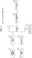
- Fig. 4 is a block diagram schematically illustrating main part of the bill distinguishing unit.
- the bill distinguishing unit 20 includes a control part 21, an illumination part 22, a lighting part 23, a light receiving part 24, a detection part 25, a distinguishing part 26, a memory part 27 and an input/output part 28.
- the bill distinguishing unit 20 reads reflected images of bills and distinguishes denominations and genuineness of bills on the reflected images.
- the control part 21 controls operation of respective parts of the bill distinguishing unit 20.
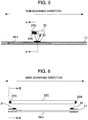
- Figs. 5 and 6 are diagrams explaining arrangement of light emitting part and light receiving part.
- Fig. 5 is a diagram as viewed in the direction of arrows B-B shown in Fig. 6.
- Fig. 6 is a diagram as viewed in the direction of arrows A-A shown in Fig. 5 .
- the right and left direction in Fig. 5 is sub-scanning direction which is conveying direction of bills.
- the right and left direction in Fig. 6 is main scanning direction which is width direction of the bill conveying path 17.
- the illumination part 22 includes a light leading member 22C extending in the main scanning direction and light emitting members 22A and 22B disposed at both ends of the light leading member 22C.
- the illumination part 22 emits light in the form of line extending in the main scanning direction.
- the illumination part 22 emits light to enter the light leading member 22C by lighting the light emitting members 22A and 22B.
- the light leading member 22C emits light entered therein from the side opposite to the bill conveying path 17 so as to irradiate bills being conveyed on the bill conveying path 17 with illumination light efficiently.
- the light leading member 22C includes reflective film coating applied on the side (excluding the end surfaces which light of the light emitting members 22A and 22B enters) which is not opposite to the bill conveying path 17 so as to limit discharge of light entered by the light emitting members 22A and 22B from the side which is not opposite to the bill conveying path 17.
- the lighting part 23 controls turning on and off of the light emitting members 22A and 22B of the illumination part 22 individually. Furthermore, the lighting part 23 controls currents flowing through the light emitting members 22A and 22B individually and also controls an amount of light emitted at the time of lighting individually.
- the light receiving part 24 is a line sensor composed of a plurality of light receiving elements.
- the plurality of light receiving elements are arranged in the main scanning direction.
- the detection part 25 detects output of the light receiving elements to thereby read reflected image for one line in the main scanning direction of bill.
- the detection part 25 links or combines one-line reflected images read repeatedly in the main scanning direction each time bills is conveyed by predetermined distance in the sub-scanning direction to produce reflected image for one bill.
- the bill distinguishing unit 20 includes reflecting plates 31 and 32 disposed at both ends of the bill conveying path 17.
- the reflecting plates 31 and 32 are disposed in positions irradiated with illumination light of the illumination part 22. Further, the reflecting plates 31 and 32 are disposed on the same side of the bill conveying path 17 as the illumination part 22 and the light receiving part 24. Accordingly, the illumination part 22 can irradiate the reflecting plates 31 and 32 with illumination light regardless of presence of bill in the bill convey path 17 and light by reflected by the reflecting plates 31 and 32 can be detected by the light receiving part 24.
- the distinguishing part 26 distinguishes denominations and genuineness of bill on the basis of reflected image of the bill obtained by the detection part 25.
- the memory part 27 stores therein parameters and the like used for operation control of the bill distinguishing unit 20.
- the input/output part informs distinguished result in the distinguishing part 26 to the bill processing unit 4.
- the bill processing unit 4 decides conveyance destination of the bill in accordance with the distinguished result notified from the bill distinguishing unit 20.
- the ATM 1 sends out bills received in the bill receiving and paying port 4A onto the bill conveying path 17 one by one and distinguishes denominations and genuineness of the bills in the bill distinguishing unit 20.
- the bill processing unit 4 conveys the received bill of which denomination and genuineness are distinguished to the temporarily holding part 16 and holds it therein.
- the bill processing unit 4 returns the bill of which at least one of denomination and genuineness cannot be distinguished to the bill receiving and paying port 4A to be returned to user.
- the ATM 1 performs receipt transaction of money in which the decided amount of money received is entered in user's account (designated account).
- This receipt transaction of money is processing of informing user's account number and amount of money received to a host apparatus.
- the card and detailed statement processing unit 6 performs issue of detailed statement on which transaction contents are printed and printing of transaction contents on the bankbook received this time by the bankbook processing unit.
- the bill processing unit 4 sends out the bills held in the temporarily holding part 16 one by one and distinguishes denominations and genuineness thereof in the bill distinguishing unit 20 again.
- the bill processing unit 4 conveys each bill to the cartridge for the denomination distinguished for each bill to be received therein.
- the bill processing unit 4 conveys the bill of which at least one of denomination and genuineness cannot be distinguished to the withdrawal cartridge 15 to be received therein.
- the ATM 1 decides the number of bills to be paid for each of the denominations of bills in accordance with the designated amount of money to be paid.
- the bill processing unit 4 sends out the decided number of bills from the denomination-classified (per-denomination) cartridges 11 to 13 for each denomination and distinguishes denominations and genuineness thereof in the bill distinguishing unit 20.
- the bill processing unit 4 conveys the bills of which denominations and genuineness can be distinguished to the bill receiving and paying port 4A to be received therein.
- the bill processing unit conveys the bills of which at least one of denominations and genuineness cannot be distinguished to the withdrawal cartridge 15 to be received therein.
- the ATM 1 When the ATM 1 receives bills corresponding to the amount of money to be paid in the bill receiving and paying port 4A, the ATM 1 performs processing for paying the amount of money to be paid from user's account (designated account).
- the paying processing is processing for informing user's account number and the amount of money to be paid to host apparatus.
- the ATM 1 opens shutter disposed in the bill receiving and paying port 4A and discharges bills received within the bill receiving and paying port 4A to user. Further, the card and detailed statement processing unit 6 performs issue of detailed statement on which transaction contents are printed and printing of transaction contents on the bankbook received this time by the bankbook processing unit 7.
- the bill distinguishing unit 20 distinguishes denominations and genuineness of bills using reflected image of bills. Although description is not made here, the bill distinguishing unit 20 detects magnetic pattern, thickness and the like of bills and synthetically or comprehensively distinguishes denominations and genuineness of bills.
- the bill distinguishing unit 20 stores therein initial light amount distribution patterns L0(X) and R0(X) shown in Figs. 7 and 8 .
- the initial light amount distribution pattern L0(X) shown in Fig. 7 is output of light receiving elements included in the light receiving part 24 and arranged in the main scanning direction when the reflecting plates for reference are put on the bill conveying path 17 in the state that the light emitting member 22A is turned on and the light emitting member 22B is turned off (first state described in the present invention).
- the initial light amount distribution pattern R0(X)shown in Fig. 8 is output of light receiving elements included in the light receiving part 24 and arranged in the main scanning direction when the reflecting plates for reference are put on the bill conveying path 17 in the state that the light emitting member 22A is turned off and the light emitting member 22B is turned on (second state described in the present invention).
- Variable X in the initial light amount distribution patterns L0(X) and R0(X) represents the light receiving element arranged in the main scanning direction.
- Currents supplied to the light emitting members 22A and 22B are individually defined so that the initial light amount distribution patterns L0(X) and R0(X)are combined to get LRO(X) having substantially uniform light amount distribution in the main scanning direction with light amount proper to read reflected image of bill as shown in Fig. 9 when both of the light emitting members 22A and 22B are turned on.
- LRO(X) is substantially equal to the sum of L0(X) and R0(X).
- the light emission amount of the light emitting members 22A and 22B to supplied current is reduced due to aging and the like.
- the light amount distribution pattern L(X) obtained when the light emitting member 22A is turned on and the light emitting member 22B is turned off is varied to distribution shown in Fig. 10 due to aging and the like of the light emitting member 22A.
- the light amount distribution pattern R(X) obtained when the light emitting member 22A is turned off and the light emitting member 22B is turned on is varied to distribution shown in Fig. 11 due to aging and the like of the light emitting member 22B.
- Variation of the light amount distribution patterns shown in Figs. 10 and 11 contains not only aging of the light emitting members 22A and 22B but also aging and the like of the light receiving part 24.
- the degree of reduction in light amount of the light emitting member 22A is not the same as that of the light emitting member 22B.
- Fig. 12 is a flow chart showing correction processing. This correction processing is performed in advance of distinguishing of bills when transaction of handling bills such as receipt and payment transactions of money is processed.
- the correction processing is processing for making the light amount distribution of line-shaped illumination light emitted in the main scanning direction by the illumination part 22 equal to the initial light amount distribution LRO(X) shown in Fig. 9 .
- the bill distinguishing unit 20 turns on both of light emitting members 22A and 22B and detects the reflected light amounts of the reflecting plates 31 and 32 (S1).
- a current value supplied to the light emitting member 22A is a current value supplied when the initial light amount distribution pattern L0(X) is obtained.
- a current value supplied to the light emitting member 22B is a current value supplied when the initial light amount distribution pattern R0(X)is obtained.
- LR M ⁇ ⁇ L 0 M + ⁇ ⁇ R 0 M
- LR N ⁇ ⁇ L 0 N + ⁇ ⁇ R 0 N
- the bill distinguishing unit 20 calculates ⁇ and ⁇ using the reflected light amount LR(M) from the reflecting plate 31 detected in step S1 and the reflected light amount LR(N) from the reflecting plate 32 (S2).
- step S2 first-degree simultaneous equations in two unknowns expressed by the following equations are solved to calculate ⁇ and ⁇ .
- LR M ⁇ L 0 M + ⁇ ⁇ R 0 M
- LR N ⁇ L 0 N + ⁇ ⁇ R 0 N
- the bill distinguishing unit 20 decides the current value supplied to the light emitting member 22A in accordance with ⁇ calculated in step S2 and decides the current value supplied to the light emitting member 22B in accordance with ⁇ calculated in step S2 (S3).
- the lighting part 23 sets the currents supplied to the light emitting members 22A and 22B to the current values decided in step S3.
- the light amount distribution LR(X) of line-shaped illumination light with which the illumination part 22 irradiates the bills being conveyed along the bill conveying path can be made to be substantially equal to the light amount distribution LRO(X) at the time of the initial setting. That is, the line-shaped illumination light with which bills are irradiated can be corrected to proper light amount distribution (light amount distribution LRO(X) at the time of initial setting) without influence by reduction of the light emission amount due to aging and the like of the light emitting members 22A and 22B. Accordingly, reduction of the distinguishing accuracy for denominations and genuineness of bills can be suppressed.
- the lighting part 23 changes currents supplied to the light emitting members 22A and 22B in accordance with ⁇ and ⁇ calculated in step S2, although an amplification factor for amplifying by the detection part 25 outputs of the light receiving elements of the light receiving part 24 may be changed. Further, the amplification factor can be set for each of the light receiving elements. Concretely, the output of each light receiving element is estimated by comparison of initial light amount distribution pattern LRO(X) and current light amount distribution pattern LR(X) estimated from ⁇ and ⁇ calculated in step S2. The amplification factor may be changed on the basis of the ratio of output of each light receiving element at initial light amount distribution pattern LRO(X) and output of each light receiving element at current light amount distribution pattern LR(X). In this case, the configuration for adjusting light emission amounts of the light emitting members 22A and 22b can be eliminated and it can cope with even rough adjustment.
- the present invention can be applied to not only the above bill distinguishing unit 20 but also any apparatus as far as the apparatus can read reflected image of paper such as check, securities and manuscript.
Landscapes
- Health & Medical Sciences (AREA)
- General Health & Medical Sciences (AREA)
- Toxicology (AREA)
- Engineering & Computer Science (AREA)
- Multimedia (AREA)
- Signal Processing (AREA)
- Physics & Mathematics (AREA)
- General Physics & Mathematics (AREA)
- Inspection Of Paper Currency And Valuable Securities (AREA)
- Image Input (AREA)
- Financial Or Insurance-Related Operations Such As Payment And Settlement (AREA)
Claims (3)
- Leseeinheit für ein reflektiertes Bild, die ein Beleuchtungsteil (22) und ein Lichtempfangsteil (24), das auf einer Seite gegenüber einem zu lesenden Objekt, das längs eines Transportpfads (17) transportiert wird, angeordnet ist, umfasst,
wobei das Beleuchtungsteil (22) das Objekt, das transportiert wird, mit Beleuchtungslicht in Form einer Linie in Breitenrichtung des Objekts bestrahlt,
wobei das Lichtempfangsteil (24) mehrere Lichtempfangselemente umfasst, die in Breitenrichtung des Objekts, das transportiert wird, angeordnet sind, um durch die mehreren Lichtempfangselemente Licht zu detektieren, das durch das Objekt reflektiert wird,
wobei
das Beleuchtungsteil (22) ein Lichtleitelement (22C), das sich in Breitenrichtung des Transportpfads (17) erstreckt, und Lichtausstrahlungselemente (22A, 22B), die an beiden Enden des Lichtleitelements (22C) angeordnet sind, damit Licht in das Lichtleitelement (22C) eintritt, umfasst,
und wobei die Leseeinheit für ein reflektiertes Bild Folgendes umfasst:
reflektierende Platten (31, 32), die an beiden Enden des Lichtleitelements (22C) gegenüber dem Lichtleitelement (22C) angeordnet sind,
ein Speicherteil (27), um darin ein erstes Referenzmuster einer Lichtmengenverteilung des linienförmigen Beleuchtungslichts, das durch das Lichtleitelement (22C) ausgestrahlt wird, in einem ersten Zustand, in dem das Lichtausstrahlungselement (22A), das an einem Ende des Lichtleitelements (22C) angeordnet ist, eingeschaltet ist und das Lichtausstrahlungselement (22B), das an dem anderen Ende angeordnet ist, ausgeschaltet ist, und ein zweites Referenzmuster einer Lichtmengenverteilung des linienförmigen Beleuchtungslichts, das durch das Lichtleitelement (22C) ausgestrahlt wird, in einem zweiten Zustand, in dem das Lichtausstrahlungselement (22A), das an einem Ende des Lichtleitelements (22C) angeordnet ist, ausgeschaltet ist und das Lichtausstrahlungselement (22B), das an dem anderen Ende angeordnet ist, eingeschaltet ist, zu speichern,
dadurch gekennzeichnet, dass
ein Teil zur Berechnung eines Korrekturkoeffizienten bereitgestellt ist, um reflektiertes Licht von jeder der reflektierenden Platten (31, 32), die in Bezug auf beide Enden des Lichtleitelements (22C) gegenüberliegend angeordnet sind, in einem dritten Zustand, in dem die beiden Lichtausstrahlungselemente (22A, 22B), die an beiden Enden des Lichtleitelements (22C) angeordnet sind, durch das Lichtempfangsteil (24) eingeschaltet sind, zu detektieren, und um auf der Basis einer Menge des reflektierten Lichts, das für jede der reflektierenden Platten (31, 32) detektiert wird, und des ersten und des zweiten Referenzmusters, die in dem Speicherteil (27) gespeichert sind, einen Korrekturkoeffizienten zu berechnen, der beim Lesen eines reflektierten Bilds des Objekts verwendet wird. - Leseeinheit für ein reflektiertes Bild nach Anspruch 1, wobei
das Teil zum Berechnen des Korrekturkoeffizienten einen Grad einer Verringerung der Lichtmenge von jedem der Lichtausstrahlungselemente (22A, 22B) als den Korrekturkoeffizienten verwendet. - Leseeinheit für ein reflektiertes Bild nach Anspruch 1 oder 2, wobei
das Speicherteil (27) die Menge an reflektiertem Licht, die durch das Lichtempfangsbauteil (24) von jeder der reflektierenden Platten (31, 32) in den jeweiligen Zuständen detektiert wird, als das erste und das zweite Referenzmuster speichert.
Applications Claiming Priority (1)
| Application Number | Priority Date | Filing Date | Title |
|---|---|---|---|
| JP2009274209A JP4979756B2 (ja) | 2009-12-02 | 2009-12-02 | 反射画像読取ユニット |
Publications (3)
| Publication Number | Publication Date |
|---|---|
| EP2334048A2 EP2334048A2 (de) | 2011-06-15 |
| EP2334048A3 EP2334048A3 (de) | 2011-08-24 |
| EP2334048B1 true EP2334048B1 (de) | 2018-06-20 |
Family
ID=43510874
Family Applications (1)
| Application Number | Title | Priority Date | Filing Date |
|---|---|---|---|
| EP10192489.2A Not-in-force EP2334048B1 (de) | 2009-12-02 | 2010-11-25 | Einheit zum Lesen reflektierter Bilder |
Country Status (4)
| Country | Link |
|---|---|
| EP (1) | EP2334048B1 (de) |
| JP (1) | JP4979756B2 (de) |
| KR (1) | KR101165761B1 (de) |
| CN (1) | CN102087763B (de) |
Families Citing this family (4)
| Publication number | Priority date | Publication date | Assignee | Title |
|---|---|---|---|---|
| JP5561309B2 (ja) * | 2012-04-26 | 2014-07-30 | 沖電気工業株式会社 | 現金取扱装置 |
| CN107437295B (zh) * | 2016-05-26 | 2020-08-21 | 山东新北洋信息技术股份有限公司 | 纸币处理装置的扫描模块校正方法及装置 |
| JP6867270B2 (ja) | 2017-10-19 | 2021-04-28 | グローリー株式会社 | 光ラインセンサユニット |
| US12477233B2 (en) | 2021-04-23 | 2025-11-18 | Mitsubishi Electric Corporation | In-vehicle exposure control device and exposure control method |
Family Cites Families (4)
| Publication number | Priority date | Publication date | Assignee | Title |
|---|---|---|---|---|
| JP4522952B2 (ja) * | 2006-01-18 | 2010-08-11 | 三菱電機株式会社 | 画像読取装置 |
| JP5021942B2 (ja) * | 2006-02-28 | 2012-09-12 | 日立オムロンターミナルソリューションズ株式会社 | イメージセンサ及び識別装置及びその補正方法 |
| JP2008244985A (ja) * | 2007-03-28 | 2008-10-09 | Mitsubishi Electric Corp | ライン照明装置及びこれを用いた画像入力装置 |
| JP2009118142A (ja) * | 2007-11-06 | 2009-05-28 | Pfu Ltd | 画像読取装置 |
-
2009
- 2009-12-02 JP JP2009274209A patent/JP4979756B2/ja not_active Expired - Fee Related
-
2010
- 2010-10-25 KR KR1020100103930A patent/KR101165761B1/ko not_active Expired - Fee Related
- 2010-11-25 EP EP10192489.2A patent/EP2334048B1/de not_active Not-in-force
- 2010-12-01 CN CN2010105731289A patent/CN102087763B/zh active Active
Non-Patent Citations (1)
| Title |
|---|
| None * |
Also Published As
| Publication number | Publication date |
|---|---|
| EP2334048A3 (de) | 2011-08-24 |
| JP2011118566A (ja) | 2011-06-16 |
| CN102087763B (zh) | 2013-12-04 |
| KR20110063288A (ko) | 2011-06-10 |
| EP2334048A2 (de) | 2011-06-15 |
| CN102087763A (zh) | 2011-06-08 |
| JP4979756B2 (ja) | 2012-07-18 |
| KR101165761B1 (ko) | 2012-07-18 |
Similar Documents
| Publication | Publication Date | Title |
|---|---|---|
| US20050056519A1 (en) | Bill handling machine | |
| US7631743B2 (en) | Apparatus and a method for processing paper currency | |
| US20150178692A1 (en) | Valuable medium processing apparatus | |
| CN102376118A (zh) | 纸张类处理系统及纸张类判别装置 | |
| CN103177503B (zh) | 纸币操作装置及现金自动交易装置 | |
| US7699153B2 (en) | Method for identifying counterfeit banknotes | |
| WO2014024613A1 (ja) | 貨幣処理機、貨幣処理システムおよび貨幣処理方法 | |
| JP5602674B2 (ja) | 紙葉類処理装置、および識別アルゴリズム更新プログラム | |
| KR101178001B1 (ko) | 매체 이미지 검출장치, 매체 이미지 검출방법 및 이를 이용한 금융기기 | |
| EP2334048A2 (de) | Einheit zum Lesen reflektierter Bilder | |
| US11055679B2 (en) | Bunch document recycler | |
| CN104346878B (zh) | 自动交易装置、自动交易系统以及纸币交换交易方法 | |
| JP3856715B2 (ja) | 紙葉類識別装置及び自動取引装置 | |
| KR101544095B1 (ko) | 지폐일련번호 독취가 가능한 금융자동화기기 및 이를 이용한 지폐관리방법 | |
| JP2003263669A5 (de) | ||
| EP3716232B1 (de) | Geldhandhabungsvorrichtung und verfahren zur steuerung der geldhandhabungsvorrichtung | |
| RU2677708C1 (ru) | Устройство для обработки бумажных листов и способ обработки бумажных листов | |
| JP4979759B2 (ja) | 光学センサ、および識別ユニット | |
| JP4952144B2 (ja) | 自動取引装置 | |
| JP5313052B2 (ja) | 取引処理装置 | |
| JP6300612B2 (ja) | 商品券処理機、商品券処理システムおよび商品券処理方法 | |
| JP2011103088A (ja) | 紙葉類識別ユニット、および紙葉類処理装置 | |
| JP2004295782A (ja) | 貨幣取引装置及び紙幣情報の管理システム | |
| JP2022052095A (ja) | 制御方法 | |
| JP2013142969A (ja) | 紙葉類搬送装置 |
Legal Events
| Date | Code | Title | Description |
|---|---|---|---|
| PUAI | Public reference made under article 153(3) epc to a published international application that has entered the european phase |
Free format text: ORIGINAL CODE: 0009012 |
|
| 17P | Request for examination filed |
Effective date: 20110325 |
|
| AK | Designated contracting states |
Kind code of ref document: A2 Designated state(s): AL AT BE BG CH CY CZ DE DK EE ES FI FR GB GR HR HU IE IS IT LI LT LU LV MC MK MT NL NO PL PT RO RS SE SI SK SM TR |
|
| AX | Request for extension of the european patent |
Extension state: BA ME |
|
| PUAL | Search report despatched |
Free format text: ORIGINAL CODE: 0009013 |
|
| AK | Designated contracting states |
Kind code of ref document: A3 Designated state(s): AL AT BE BG CH CY CZ DE DK EE ES FI FR GB GR HR HU IE IS IT LI LT LU LV MC MK MT NL NO PL PT RO RS SE SI SK SM TR |
|
| AX | Request for extension of the european patent |
Extension state: BA ME |
|
| RIC1 | Information provided on ipc code assigned before grant |
Ipc: G07D 11/00 20060101ALI20110715BHEP Ipc: H04N 1/48 20060101AFI20110715BHEP Ipc: G07D 7/12 20060101ALI20110715BHEP |
|
| GRAP | Despatch of communication of intention to grant a patent |
Free format text: ORIGINAL CODE: EPIDOSNIGR1 |
|
| STAA | Information on the status of an ep patent application or granted ep patent |
Free format text: STATUS: GRANT OF PATENT IS INTENDED |
|
| INTG | Intention to grant announced |
Effective date: 20180108 |
|
| GRAS | Grant fee paid |
Free format text: ORIGINAL CODE: EPIDOSNIGR3 |
|
| GRAA | (expected) grant |
Free format text: ORIGINAL CODE: 0009210 |
|
| STAA | Information on the status of an ep patent application or granted ep patent |
Free format text: STATUS: THE PATENT HAS BEEN GRANTED |
|
| AK | Designated contracting states |
Kind code of ref document: B1 Designated state(s): AL AT BE BG CH CY CZ DE DK EE ES FI FR GB GR HR HU IE IS IT LI LT LU LV MC MK MT NL NO PL PT RO RS SE SI SK SM TR |
|
| RAP1 | Party data changed (applicant data changed or rights of an application transferred) |
Owner name: HITACHI-OMRON TERMINAL SOLUTIONS, CORPORATION |
|
| REG | Reference to a national code |
Ref country code: GB Ref legal event code: FG4D |
|
| REG | Reference to a national code |
Ref country code: IE Ref legal event code: FG4D |
|
| REG | Reference to a national code |
Ref country code: AT Ref legal event code: REF Ref document number: 1011382 Country of ref document: AT Kind code of ref document: T Effective date: 20180715 |
|
| REG | Reference to a national code |
Ref country code: DE Ref legal event code: R096 Ref document number: 602010051378 Country of ref document: DE |
|
| REG | Reference to a national code |
Ref country code: NL Ref legal event code: MP Effective date: 20180620 |
|
| PG25 | Lapsed in a contracting state [announced via postgrant information from national office to epo] |
Ref country code: LT Free format text: LAPSE BECAUSE OF FAILURE TO SUBMIT A TRANSLATION OF THE DESCRIPTION OR TO PAY THE FEE WITHIN THE PRESCRIBED TIME-LIMIT Effective date: 20180620 Ref country code: SE Free format text: LAPSE BECAUSE OF FAILURE TO SUBMIT A TRANSLATION OF THE DESCRIPTION OR TO PAY THE FEE WITHIN THE PRESCRIBED TIME-LIMIT Effective date: 20180620 Ref country code: NO Free format text: LAPSE BECAUSE OF FAILURE TO SUBMIT A TRANSLATION OF THE DESCRIPTION OR TO PAY THE FEE WITHIN THE PRESCRIBED TIME-LIMIT Effective date: 20180920 Ref country code: BG Free format text: LAPSE BECAUSE OF FAILURE TO SUBMIT A TRANSLATION OF THE DESCRIPTION OR TO PAY THE FEE WITHIN THE PRESCRIBED TIME-LIMIT Effective date: 20180920 Ref country code: FI Free format text: LAPSE BECAUSE OF FAILURE TO SUBMIT A TRANSLATION OF THE DESCRIPTION OR TO PAY THE FEE WITHIN THE PRESCRIBED TIME-LIMIT Effective date: 20180620 |
|
| REG | Reference to a national code |
Ref country code: LT Ref legal event code: MG4D |
|
| PG25 | Lapsed in a contracting state [announced via postgrant information from national office to epo] |
Ref country code: RS Free format text: LAPSE BECAUSE OF FAILURE TO SUBMIT A TRANSLATION OF THE DESCRIPTION OR TO PAY THE FEE WITHIN THE PRESCRIBED TIME-LIMIT Effective date: 20180620 Ref country code: LV Free format text: LAPSE BECAUSE OF FAILURE TO SUBMIT A TRANSLATION OF THE DESCRIPTION OR TO PAY THE FEE WITHIN THE PRESCRIBED TIME-LIMIT Effective date: 20180620 Ref country code: GR Free format text: LAPSE BECAUSE OF FAILURE TO SUBMIT A TRANSLATION OF THE DESCRIPTION OR TO PAY THE FEE WITHIN THE PRESCRIBED TIME-LIMIT Effective date: 20180921 Ref country code: HR Free format text: LAPSE BECAUSE OF FAILURE TO SUBMIT A TRANSLATION OF THE DESCRIPTION OR TO PAY THE FEE WITHIN THE PRESCRIBED TIME-LIMIT Effective date: 20180620 |
|
| REG | Reference to a national code |
Ref country code: AT Ref legal event code: MK05 Ref document number: 1011382 Country of ref document: AT Kind code of ref document: T Effective date: 20180620 |
|
| PG25 | Lapsed in a contracting state [announced via postgrant information from national office to epo] |
Ref country code: NL Free format text: LAPSE BECAUSE OF FAILURE TO SUBMIT A TRANSLATION OF THE DESCRIPTION OR TO PAY THE FEE WITHIN THE PRESCRIBED TIME-LIMIT Effective date: 20180620 |
|
| PG25 | Lapsed in a contracting state [announced via postgrant information from national office to epo] |
Ref country code: AT Free format text: LAPSE BECAUSE OF FAILURE TO SUBMIT A TRANSLATION OF THE DESCRIPTION OR TO PAY THE FEE WITHIN THE PRESCRIBED TIME-LIMIT Effective date: 20180620 Ref country code: EE Free format text: LAPSE BECAUSE OF FAILURE TO SUBMIT A TRANSLATION OF THE DESCRIPTION OR TO PAY THE FEE WITHIN THE PRESCRIBED TIME-LIMIT Effective date: 20180620 Ref country code: IS Free format text: LAPSE BECAUSE OF FAILURE TO SUBMIT A TRANSLATION OF THE DESCRIPTION OR TO PAY THE FEE WITHIN THE PRESCRIBED TIME-LIMIT Effective date: 20181020 Ref country code: SK Free format text: LAPSE BECAUSE OF FAILURE TO SUBMIT A TRANSLATION OF THE DESCRIPTION OR TO PAY THE FEE WITHIN THE PRESCRIBED TIME-LIMIT Effective date: 20180620 Ref country code: RO Free format text: LAPSE BECAUSE OF FAILURE TO SUBMIT A TRANSLATION OF THE DESCRIPTION OR TO PAY THE FEE WITHIN THE PRESCRIBED TIME-LIMIT Effective date: 20180620 Ref country code: PL Free format text: LAPSE BECAUSE OF FAILURE TO SUBMIT A TRANSLATION OF THE DESCRIPTION OR TO PAY THE FEE WITHIN THE PRESCRIBED TIME-LIMIT Effective date: 20180620 Ref country code: CZ Free format text: LAPSE BECAUSE OF FAILURE TO SUBMIT A TRANSLATION OF THE DESCRIPTION OR TO PAY THE FEE WITHIN THE PRESCRIBED TIME-LIMIT Effective date: 20180620 |
|
| PG25 | Lapsed in a contracting state [announced via postgrant information from national office to epo] |
Ref country code: ES Free format text: LAPSE BECAUSE OF FAILURE TO SUBMIT A TRANSLATION OF THE DESCRIPTION OR TO PAY THE FEE WITHIN THE PRESCRIBED TIME-LIMIT Effective date: 20180620 Ref country code: SM Free format text: LAPSE BECAUSE OF FAILURE TO SUBMIT A TRANSLATION OF THE DESCRIPTION OR TO PAY THE FEE WITHIN THE PRESCRIBED TIME-LIMIT Effective date: 20180620 Ref country code: IT Free format text: LAPSE BECAUSE OF FAILURE TO SUBMIT A TRANSLATION OF THE DESCRIPTION OR TO PAY THE FEE WITHIN THE PRESCRIBED TIME-LIMIT Effective date: 20180620 |
|
| REG | Reference to a national code |
Ref country code: DE Ref legal event code: R097 Ref document number: 602010051378 Country of ref document: DE |
|
| PLBE | No opposition filed within time limit |
Free format text: ORIGINAL CODE: 0009261 |
|
| STAA | Information on the status of an ep patent application or granted ep patent |
Free format text: STATUS: NO OPPOSITION FILED WITHIN TIME LIMIT |
|
| 26N | No opposition filed |
Effective date: 20190321 |
|
| PG25 | Lapsed in a contracting state [announced via postgrant information from national office to epo] |
Ref country code: DK Free format text: LAPSE BECAUSE OF FAILURE TO SUBMIT A TRANSLATION OF THE DESCRIPTION OR TO PAY THE FEE WITHIN THE PRESCRIBED TIME-LIMIT Effective date: 20180620 |
|
| REG | Reference to a national code |
Ref country code: CH Ref legal event code: PL |
|
| GBPC | Gb: european patent ceased through non-payment of renewal fee |
Effective date: 20181125 |
|
| PG25 | Lapsed in a contracting state [announced via postgrant information from national office to epo] |
Ref country code: MC Free format text: LAPSE BECAUSE OF FAILURE TO SUBMIT A TRANSLATION OF THE DESCRIPTION OR TO PAY THE FEE WITHIN THE PRESCRIBED TIME-LIMIT Effective date: 20180620 Ref country code: LU Free format text: LAPSE BECAUSE OF NON-PAYMENT OF DUE FEES Effective date: 20181125 |
|
| REG | Reference to a national code |
Ref country code: BE Ref legal event code: MM Effective date: 20181130 |
|
| REG | Reference to a national code |
Ref country code: IE Ref legal event code: MM4A |
|
| PG25 | Lapsed in a contracting state [announced via postgrant information from national office to epo] |
Ref country code: SI Free format text: LAPSE BECAUSE OF FAILURE TO SUBMIT A TRANSLATION OF THE DESCRIPTION OR TO PAY THE FEE WITHIN THE PRESCRIBED TIME-LIMIT Effective date: 20180620 Ref country code: LI Free format text: LAPSE BECAUSE OF NON-PAYMENT OF DUE FEES Effective date: 20181130 Ref country code: CH Free format text: LAPSE BECAUSE OF NON-PAYMENT OF DUE FEES Effective date: 20181130 |
|
| PG25 | Lapsed in a contracting state [announced via postgrant information from national office to epo] |
Ref country code: FR Free format text: LAPSE BECAUSE OF NON-PAYMENT OF DUE FEES Effective date: 20181130 Ref country code: IE Free format text: LAPSE BECAUSE OF NON-PAYMENT OF DUE FEES Effective date: 20181125 |
|
| PG25 | Lapsed in a contracting state [announced via postgrant information from national office to epo] |
Ref country code: BE Free format text: LAPSE BECAUSE OF NON-PAYMENT OF DUE FEES Effective date: 20181130 Ref country code: AL Free format text: LAPSE BECAUSE OF FAILURE TO SUBMIT A TRANSLATION OF THE DESCRIPTION OR TO PAY THE FEE WITHIN THE PRESCRIBED TIME-LIMIT Effective date: 20180620 |
|
| PG25 | Lapsed in a contracting state [announced via postgrant information from national office to epo] |
Ref country code: GB Free format text: LAPSE BECAUSE OF NON-PAYMENT OF DUE FEES Effective date: 20181125 |
|
| PG25 | Lapsed in a contracting state [announced via postgrant information from national office to epo] |
Ref country code: MT Free format text: LAPSE BECAUSE OF NON-PAYMENT OF DUE FEES Effective date: 20181125 |
|
| PG25 | Lapsed in a contracting state [announced via postgrant information from national office to epo] |
Ref country code: TR Free format text: LAPSE BECAUSE OF FAILURE TO SUBMIT A TRANSLATION OF THE DESCRIPTION OR TO PAY THE FEE WITHIN THE PRESCRIBED TIME-LIMIT Effective date: 20180620 |
|
| PG25 | Lapsed in a contracting state [announced via postgrant information from national office to epo] |
Ref country code: PT Free format text: LAPSE BECAUSE OF FAILURE TO SUBMIT A TRANSLATION OF THE DESCRIPTION OR TO PAY THE FEE WITHIN THE PRESCRIBED TIME-LIMIT Effective date: 20180620 |
|
| PG25 | Lapsed in a contracting state [announced via postgrant information from national office to epo] |
Ref country code: CY Free format text: LAPSE BECAUSE OF FAILURE TO SUBMIT A TRANSLATION OF THE DESCRIPTION OR TO PAY THE FEE WITHIN THE PRESCRIBED TIME-LIMIT Effective date: 20180620 Ref country code: HU Free format text: LAPSE BECAUSE OF FAILURE TO SUBMIT A TRANSLATION OF THE DESCRIPTION OR TO PAY THE FEE WITHIN THE PRESCRIBED TIME-LIMIT; INVALID AB INITIO Effective date: 20101125 Ref country code: MK Free format text: LAPSE BECAUSE OF NON-PAYMENT OF DUE FEES Effective date: 20180620 |
|
| PGFP | Annual fee paid to national office [announced via postgrant information from national office to epo] |
Ref country code: DE Payment date: 20210929 Year of fee payment: 12 |
|
| REG | Reference to a national code |
Ref country code: DE Ref legal event code: R119 Ref document number: 602010051378 Country of ref document: DE |
|
| PG25 | Lapsed in a contracting state [announced via postgrant information from national office to epo] |
Ref country code: DE Free format text: LAPSE BECAUSE OF NON-PAYMENT OF DUE FEES Effective date: 20230601 |