EP3715792B1 - Verfahren und vorrichtung zum zeichnen von schnittpunkten - Google Patents
Verfahren und vorrichtung zum zeichnen von schnittpunkten Download PDFInfo
- Publication number
- EP3715792B1 EP3715792B1 EP20165079.3A EP20165079A EP3715792B1 EP 3715792 B1 EP3715792 B1 EP 3715792B1 EP 20165079 A EP20165079 A EP 20165079A EP 3715792 B1 EP3715792 B1 EP 3715792B1
- Authority
- EP
- European Patent Office
- Prior art keywords
- road
- line
- lines
- side line
- target
- Prior art date
- Legal status (The legal status is an assumption and is not a legal conclusion. Google has not performed a legal analysis and makes no representation as to the accuracy of the status listed.)
- Active
Links
Images

Classifications
-
- G—PHYSICS
- G01—MEASURING; TESTING
- G01C—MEASURING DISTANCES, LEVELS OR BEARINGS; SURVEYING; NAVIGATION; GYROSCOPIC INSTRUMENTS; PHOTOGRAMMETRY OR VIDEOGRAMMETRY
- G01C21/00—Navigation; Navigational instruments not provided for in groups G01C1/00 - G01C19/00
- G01C21/26—Navigation; Navigational instruments not provided for in groups G01C1/00 - G01C19/00 specially adapted for navigation in a road network
- G01C21/34—Route searching; Route guidance
- G01C21/36—Input/output arrangements for on-board computers
- G01C21/3667—Display of a road map
-
- G—PHYSICS
- G06—COMPUTING OR CALCULATING; COUNTING
- G06T—IMAGE DATA PROCESSING OR GENERATION, IN GENERAL
- G06T11/00—Two-dimensional [2D] image generation
- G06T11/20—Drawing from basic elements
- G06T11/23—Drawing from basic elements using straight lines or curves
-
- G—PHYSICS
- G06—COMPUTING OR CALCULATING; COUNTING
- G06F—ELECTRIC DIGITAL DATA PROCESSING
- G06F30/00—Computer-aided design [CAD]
- G06F30/10—Geometric CAD
- G06F30/13—Architectural design, e.g. computer-aided architectural design [CAAD] related to design of buildings, bridges, landscapes, production plants or roads
-
- G—PHYSICS
- G06—COMPUTING OR CALCULATING; COUNTING
- G06T—IMAGE DATA PROCESSING OR GENERATION, IN GENERAL
- G06T11/00—Two-dimensional [2D] image generation
- G06T11/20—Drawing from basic elements
-
- G—PHYSICS
- G06—COMPUTING OR CALCULATING; COUNTING
- G06T—IMAGE DATA PROCESSING OR GENERATION, IN GENERAL
- G06T2207/00—Indexing scheme for image analysis or image enhancement
- G06T2207/30—Subject of image; Context of image processing
- G06T2207/30236—Traffic on road, railway or crossing
Definitions
- Embodiments of the present disclosure relate to the field of maps, and more particularly, to a method and a device for drawing an intersection, a server and a storage medium.
- US 2001/012981 A1 discloses an intersection display method, and a map display unit and a recording medium for realizing the method.
- WO 2017/166687 A1 discloses a method and apparatus for generating three-dimensional intersection roadway model, and a storage medium.
- CN 109 297 501 A discloses a method for automatically generating dual line network by GIS single line network.
- CN 107 478 201A discloses a digital road acquisition method and device based on digital ortho-images.
- a method according to claim 1 is provided.
- a device according to claim 9 is provided.
- a computer readable storage medium according to claim 13 is provided.
- the road lines all branches at the intersection are obtained based on the vector data of the intersection, the road surfaces are acquired by line-to-surface expansion, and a rough intersection is drawn, and then by drawing the corner arc at the target side line pair, a fine intersection can be obtained, such that the high-definition intersection can be drawn quickly, the intersection can be drawn in fine detail, the costs of manual drawing can be reduced, the drawn intersection is close to the real world, and the accuracy of drawing the intersection can be improved.
- the high-definition intersection is generally drawn manually or by calculating a convex hull.
- this manner requires the operator to have rich professional knowledge, be proficient in using drawing software, and this manner also has complex operations, long cycles, and slow update speeds, and for tens of millions of intersections, this manner is difficult to deal with quickly.
- the convex hull calculation method is simple to realize and can quickly construct a simple intersection, this manner has poor presentation effect, which is far from the actual intersection shape.
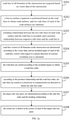
- FIG. 1a is a flowchart of a method for drawing an intersection according to some embodiments of the present disclosure. The embodiment may be applied to the case of drawing a high-definition intersection.
- the method may be performed by a device for drawing an intersection, and the device may be implemented by software and/or hardware, and be configured in a server. As shown in FIG. 1a , the method may include the following operations.
- road line of all branches at the intersection are acquired based on vector data of the intersection.
- the raw data of the base map may include vector data of the intersection, which includes line data and line relationship data of any intersection, and records the road line of each of the branches at the intersection and the intersection point of each road line, and the road lines of all branches at the intersection can be acquired according to the line data and the line relationship data.
- an N table is generally configured to represent the line relationship.
- the N table records coordinates of the feature point N of the intersection, i.e., the intersection point of respective road lines, and road segment data of all branches associated with the feature point N at the intersection, i.e., the road line.
- the feature point N may be the center point of the intersection.
- a line-to-surface expansion is performed based on the road lines to obtain road surfaces, and two side lines of each of the road surfaces are obtained.
- the line-to-surface expansion may be performed based on each road line to obtain the road surfaces of all branches at the intersection.
- the two sides parallel to the road line are the side lines, and each road surface has two side lines.
- the line-to-surface expansion may include acts of: based on each road line, expanding to both sides of the road line by taking an intersection width as the expansion distance, to obtain the two side lines of each of the road surfaces of all branches at the intersection.
- the feature point N is the center point of the intersection
- the road line is the center line of the branch, thus expansion to both sides of the center line may be performed by taking each road line as the center line and half of the intersection width as the expansion distance, and road surfaces of all branches at the intersection may be obtained.
- the expansion distance to the both sides of the center line may be a distance of other lengths determined according to the intersection width, which is not limited in the present disclosure.
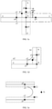
- FIG. 1b is a schematic diagram illustrating road lines and road surfaces according to some embodiments of the present disclosure, as shown in FIG. 1b , the point N is the center point of the intersection, four lines a, b, c, and d are four road lines of four branches, and S1, S2, S3 and S4 are four road surfaces obtained by line-to-surface expansion.
- the side lines of the road surface S1 include a1 and a2
- the side lines of the road surface S2 include b1 and b2
- the side lines of the road surface S3 include c1 and c2
- the side lines of the road surface S4 include d1 and d2.
- target side line pairs are determined based on side lines of the intersection, and a corner arc is drawn at the corner of each of the target side line pairs.
- each of the target side line pairs may include two side lines that do not belong to the same road line and are adjacent to each other. In actual intersections, most corners of two adjacent branches are not right angles, and are arc, thus the two side lines that need to draw the arc needs to be found based on the road surfaces, and the corner arc needs to be drawn at the corner of each target side line pair.
- the two side lines in the target side line pair that needs to draw the corner arc belong to different road lines and are adjacent to each other. In an example, as illustrated in FIG. 1b , taking the road line as the center line, a2 and b1, b2 and c1, c2 and d1, and d2 and a1 are four target side line pairs.
- the corner arc may be drawn by, for example, an arc function, a five-point smoothing method, a spline interpolation method, or a linear fitting method, and the complexity and effect of different methods may be different.
- a Bezier curve function may be used to draw the corner arc
- the Bezier curve may ensure that the drawn arc is tangent to the side line with as few interpolation points as possible
- the smooth transition effect may be implemented by using the Bezier curve function.
- FIG. 1c is a schematic diagram illustrating corner arcs according to some embodiments of the present disclosure, as shown in FIG. 1c , taking the road line as the center line as an example, m1, m2, m3 and m4 are four corner arcs drawn.
- the method further includes: drawing, according to the vector data, a road convex hull based on the road surfaces of the intersection by using a convex hull method.
- the road corner is represented by a straight line.
- the method further includes: replacing the straight line in the road convex hull with the corner arc.
- the convex hull method such as Graham scan method or Jarvis stepping method may realize enclosing all the determined points with a convex polygon.
- the convex hull method may be configured to draw a simple intersection, the corner of the road is represented by the straight line in the simple intersection, and the actual situation of the intersection cannot be presented. It should be noted that, due to the imperfection of basic road vector data, the road line and the road surface may not be obtained based on the vector data, and it may be impossible to ensure that the corner arc can be drawn at the corners of all target side line pairs.
- the road lines all branches at the intersection are obtained based on the vector data of the intersection, the road surfaces are acquired by line-to-surface expansion, and a rough intersection is drawn, and then by drawing the corner arc at the target side line pair, a fine intersection can be obtained, such that the high-definition intersection can be drawn quickly, the intersection can be drawn in fine detail, the costs of manual drawing can be reduced, the drawn intersection is close to the real world, and the accuracy of drawing the intersection can be improved.
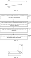
- FIG. 2a is a flowchart of a method for drawing an intersection according to an embodiment of the invention.
- the embodiment is on the basis of the above embodiments.
- the method includes the following acts.
- road lines of all branches at the intersection are acquired based on vector data of the intersection.
- a line-to-surface expansion is performed based on the road lines to obtain road surfaces, and two side lines of each of the road surfaces are obtained.
- a binding relationship between the two side lines of each road surface and the road line is recorded, and a position relationship between respective side lines and the road line to which the side line belongs is recorded, the position relationship includes being located on left or right of the road line.
- the binding relationship between the two side lines of each road surface and the road line is recorded.
- the binding relationship includes the relationship between each road line and its left and right side lines.
- FIG. 1b taking the road line being the center line as an example, it is recorded that the center line of the side line a1 and a2 is a, the side line a1 is located on the left side of the center line a, the side line a2 is located on the right side of the center line a.
- the center line b, c, d and the corresponding binding relationship can be obtained.
- road line vectors of all branches at the intersection are determined according to the vector data, and an included angle of each of the road line vectors with respect to a preset direction of a preset coordinate axis is calculated.
- the preset direction includes a positive direction and a negative direction.
- the road lines are sorted according to the included angles to obtain a road line order.
- the relationship between the road line and the side lines is obtained at block 203, and it is also determined whether the side line is located on the left or right side of the road line, thus the sorting of the side lines may be determined by the sorting of the road lines, and then based on the order of the road lines obtained and the positional relationship between the side lines and the road lines, the order of the side lines can be obtained.
- the road line vectors of all branches at the intersection are determined according to the vector data of the road, and the included angle of each of the road line vectors with respect to the preset direction of the preset coordinate axis is determined.
- the preset direction includes a positive direction and a negative direction.
- the road line is the center line
- xy axis is the preset coordinate axis
- x axis is the horizontal axis
- the y axis is the vertical axis
- the positive direction of the x axis is the preset direction.
- the included angle between the center line c and the positive direction of x axis is 0, the included angle between the center line b and the positive direction of x axis is 90, the included angle between the center line a and the positive direction of x axis is 180, and the included angle between the center line d and the positive direction of x axis is 270, when it is sorted based on the sizes of the included angles in an ascending order, the order of the center lines in a counterclockwise manner, i.e., c b, a, and d, may be obtained
- the side lines are sorted in a clockwise or counterclockwise direction to obtain the side line order.
- the side line order c2, c1, b2, b1, a2, a1, d2 and d1 may be obtained according to the center line order c, b, a, d.
- the target side line pairs are determined according to the side line order and the binding relationship.
- all target side line pairs including c1 and b2, b1 and a2, a1 and d2, and d1 and c2, can be determined.
- each road line vector with respect to the preset direction of the preset coordinate axis may be sorted in a descending order (from high to low) or ascending order (from low to high) of the included angles.
- the coordinate axis may be determined according to actual requirements, which is not limited in embodiments of the present disclosure.
- the corner arc is drawn at the corner of each of the target side line pairs.
- FIG. 2b is a schematic diagram illustrating approximately parallel side lines according to some embodiments of the present disclosure, as shown in FIG. 2b , the side lines L1 and L2 are approximately parallel, when the positive direction of the horizontal axis is the preset direction of the preset coordinate axis, according to the above method, it may be determined that the included angle corresponding to the side line L2 is less than the included angle corresponding to the side line L1.
- order of the side lines in the counterclockwise manner is L2, L1.
- the actual order of the side lines in the counterclockwise manner is L1, L2, an error occurs, and it is required to correct.
- determining the target side line pair according to the side line order and the binding relationship further includes acts of: determining whether there are at least two parallel side lines in the side lines according to a preset angle threshold; in any two target parallel side lines, selecting a target point on one of the two target parallel side lines, and determining a target position relationship between the target point and the other of the two target parallel side lines by using a cross product method; correcting the side line order according to the target position relationship; and determining the target side line pairs according to the side line order corrected and the binding relationship.
- the order of two approximately parallel side lines is corrected.
- at least two parallel side lines, such as L2 and L1 in FIG. 2b in the side lines may be determined according to the preset angle threshold.
- the preset angle threshold may be configured to determine the intersection or parallel of the side lines.
- a point K on the side line L2 is taken as the target point, a vector product of the point K and the side line L1 can be calculated by using the cross product method, and the target position relationship between the target point K and the side line L1 may be determined according to the calculation result.
- the point K is located on the left side of the side line L1.
- any point on the side line L2 should be at the right side of the side line L1.
- the order of the side lines may be corrected according to the target position relationship.
- the target side line pairs may be determined according to the side line order corrected and the binding relationship, such that the target side line pair that needs to draw the corner arc may be accurately determined, and the accuracy of drawing the intersection can be improved.
- the road lines all branches at the intersection are obtained based on the vector data of the intersection, the road surfaces are acquired by line-to-surface expansion, and a rough intersection is drawn, and then by drawing the corner arc at the target side line pair, a fine intersection can be obtained, such that the high-definition intersection can be drawn quickly, the intersection can be drawn in fine detail, the costs of manual drawing can be reduced, the drawn intersection is close to the real world.
- the accuracy of the order of the side lines determined can be improved, and the accuracy of drawing the intersection can be improved.
- FIG. 3a is a flowchart of a method for drawing an intersection according to some embodiments of the present disclosure. The embodiment is on the basis of the above embodiments. As shown in FIG. 3a , the method includes the following operations.
- road lines of all branches at the intersection are acquired based on vector data of the intersection.
- a line-to-surface expansion is performed based on the road lines to obtain road surfaces, and two side lines of each of the road surfaces are obtained.
- target side line pairs are determined based on side lines of the intersection.
- each target side line pair includes two side lines that do not belong to the same road line and are adjacent to each other.
- the corner arc is drawn at the corner of each of the target side line pairs by using a Bezier curve function.
- drawing the corner arc at the corner of each of the side line pairs by using the Bezier curve function includes acts of: for a non-parallel side line pair, drawing the corner arc by using a second-order Bezier curve function; and for a parallel side line pair, drawing the corner arc by using a third-order Bezier curve function.
- a side line pair is the parallel side line pair or the non-parallel side line pair is determined according to a preset angle threshold.
- the parallel side line pair may refer to a side line pair including two side lines that are parallel.
- the non-parallel side line pair may refer to a side line pair including two side lines that are not parallel.
- drawing the corner arc at the corner of each of the side line pairs by using the Bezier curve function further includes acts of: according to the vector data, drawing the corner arc at the corner of a target side line pair by using the third-order Bezier curve function, when the two side lines in the target side line pair intersect in a direction away from a center of the intersection to which the target side line pair belongs.
- the corner arc is drawn by using the Bezier curve function with different orders.
- the corner arc is drawn by using the second-order Bezier curve function
- the corner arc is drawn by using the third-order Bezier curve function.
- the parallel side lines here may refer to approximately parallel, i.e., the parallel of two side lines is determined according to the preset angle threshold, when the included angle of two side lines is less than the preset angle threshold, it is determined that the two side lines are parallel, and they belong to the parallel side line pair.
- the corner arc is drawn at the corner of the side line pair by using the third-order Bezier curve function.
- the two side lines in the particular side line pair are approximately parallel, when it is determined whether there is the parallel side line pair by using the preset angle threshold, in reality, some approximately parallel side line pairs may be missed due to inaccuracy of the raw vector data, thus it is necessary to select, according to the characteristics of the side line pairs, the particular side line pair that also needs to draw the corner arc by using the third-order Bezier curve function, so as to improve the accuracy.
- control points of the second-order Bezier curve function include an intersection point of each target side line pair, and foot points of an offset point on respective side lines in each target side line pair.
- the offset point is on the road line to which the target side line pair belongs.
- the control points of the third-order Bezier curve function include end points on the target side line pair close to the intersection to which the target side line pair belongs, and the foot points of the offset points on road line to which the target side line pair belongs on respective side lines in the target side line pair.
- the offset point is on the road line to which the target side line pair belongs.
- the offset point is determined by acts of: obtaining an intersection surface of the road surfaces to which the two side lines in the target side line pair belongs, and obtaining an intersection point of the road lines to which the target side line pair belongs; determining, from all points on the intersection surface, a point having a maximum distance to the intersection point of the road lines; calculating a sum of the distance and a preset threshold as an offset length; and on the road lines to which the target side line pair belongs, determining a point at the offset length from the intersection point as the offset point.
- the feature point N is the center point of the intersection
- the road line is the center line
- the intersection surface of the road surfaces S1 and S2 is S'
- the intersection point of the road lines to which the target side line pair belongs is the center point N.
- the point N' has the maximum distance to the intersection point N, and the distance between N' and N is denoted as dis.
- the offset length can be obtained by adding disc and a preset threshold delta (an experience value), and on the center lines a, b, c and d, the points p1, p2, p3 and p4 at the offset length away from the center point N are four offset points.
- the points z1 and z2 are foot points of the offset point p1 on respective side lines of the center line a, and the foot points of other offset points on their respective center lines are not shown in FIG. 3c .
- FIG. 3d illustrates control points of a second-order Bezier curve function
- FIG. 3e illustrates control points of a third-order Bezier curve function
- the control points of the second-order Bezier curve function may include the intersection point C of the side line pair a2 and b1, and the foot points z2, z3, in which z2 is the foot point of the offset point p1 on the center line a to which the side line pair belongs, z3 is the foot point of the offset point p2 on the center line b to which the side line pair belongs.
- the control points of the third-order Bezier curve function include the end points C1, C2 on the side line pair close to the intersection to which the side line pair belongs, and the foot points z2 and z3.
- the road lines all branches at the intersection are obtained based on the vector data of the intersection, the road surfaces are acquired by line-to-surface expansion, and a rough intersection is drawn, and then by drawing the corner arc at the target side line pair, a fine intersection can be obtained, such that the high-definition intersection can be drawn quickly, the intersection can be drawn in fine detail, the costs of manual drawing can be reduced, the drawn intersection is close to the real world, and the accuracy of drawing the intersection can be improved.
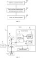
- FIG. 4 is a schematic diagram of a device for drawing an intersection according to some embodiments of the present disclosure. As shown in FIG. 4 , the device includes: a road line acquisition module 410, a line-to-surface expansion and side line acquisition module 420, and a corner arc drawing module 430.
- the road line acquisition module 410 is configured to acquire road lines of all branches at the intersection based on vector data of the intersection.
- the line-to-surface expansion and side line acquisition module 420 is configured to perform a line-to-surface expansion according to the road lines to obtain road surfaces, and acquire two side lines of each of the road surfaces.
- the corner arc drawing module 430 is configured to target side line pairs based on side lines of the intersection, and draw a corner arc at a corner of each of the target side line pairs.
- Each of the target side line pairs includes two side lines that do not belong to the same road line and are adjacent to each other.
- the line-to-surface expansion and side line acquisition module 420 is further configured to: based on each road line, expand to both sides of the road line by taking an intersection width as an expansion distance, to obtain the two side lines of each of the road surfaces of all branches at the intersection.
- the device further includes a recording module.
- the recording module is configured to record a binding relationship between the two side lines of each of the road surfaces and the road line, and record a position relationship between respective side lines and the road line to which the side line belongs. The position relationship includes being located on left or right of the road line
- the corner arc drawing module 430 includes a side line pair determining unit.
- the side line pair determining unit includes an included angle calculation subunit, a center line order determining subunit, a side line order determining subunit, and a side line pair determining subunit.
- the included angle calculation subunit is configured to determine road line vectors of all the branches at the intersection according to the vector data, and calculate an included angle of each of the road line vectors with respect to a preset direction of a preset coordinate axis.
- the preset direction includes a positive direction and a negative direction.
- the center line order determining subunit is configured to sort the road lines according to the included angles to obtain a road line order.
- the side line order determining subunit is configured to sort, according to the position relationship and the road line order, the side lines in a clockwise or counterclockwise manner to obtain a side line order.
- the side line pair determining subunit is configured to determine the target side line pairs according to the side line order and the binding relationship.
- the side line pair determining subunit is further configured to determine whether there are at least two parallel side lines according to a preset angle threshold; in any two target parallel side lines, select a target point on one of the two target parallel side lines, and determine a target position relationship between the target point and the other of the two target parallel side lines by using a cross product method; correct the side line order according to the target position relationship; and determine the target side line pairs according to the side line order corrected and the binding relationship.
- the corner arc drawing module 430 includes a corner drawing unit, which is configured to draw the corner arc at the corner of each of the target side line pairs by using a Bezier curve function.
- the corner drawing unit includes: a first corner drawing unit and a second corner drawing unit.
- the first corner drawing unit is configured to, for a non-parallel side line pair, draw the corner arc by using a second-order Bezier curve function.
- the second corner drawing unit is configured to, for a parallel side line pair, draw the corner arc by using a third-order Bezier curve function.
- whether a side line pair is the parallel side line pair or the non-parallel side line pair is determined according to a preset angle threshold.
- the corner drawing unit further includes a third corner drawing unit.
- the third corner drawing unit is configured to, according to the vector data, draw the corner arc at the corner of a target side line pair by using the third-order Bezier curve function, when the two side lines in the target side line pair intersect in a direction away from a center of the intersection to which the target side line pair belongs.
- control points of the second-order Bezier curve function include an intersection point of each target side line pair, and foot points of an offset point on respective side lines in each target side line pair.
- the offset point is on the road line to which the target side line pair belongs.
- the control points of the third-order Bezier curve function include end points on the target side line pair close to the intersection to which the target side line pair belongs, and the foot points of the offset points on road line to which the target side line pair belongs on respective side lines in the target side line pair.
- the offset point is on the road line to which the target side line pair belongs.
- the offset point is determined by acts of: obtaining an intersection surface of the road surfaces to which the two side lines in the target side line pair belongs, and obtaining an intersection point of the road lines to which the target side line pair belongs; determining, from all points on the intersection surface, a point having a maximum distance to the intersection point of the road lines; calculating a sum of the distance and a preset threshold as an offset length; and on the road lines to which the target side line pair belongs, determining a point at the offset length from the intersection point as the offset point.
- the device further includes a road convex hull drawing module, and a corner arc replacing module.
- the road convex hull drawing module is configured to draw, according to the vector data, a road convex hull based on the road surfaces by using a convex hull method.
- a road corner is represented by a straight line.
- the corner arc replacing module is configured to, after the corner arc drawing module 430 draws the corner arc at the corner of each of the target side line pairs, replace the straight line in the road convex hull with the corner arc.
- the device for drawing an intersection may perform the method for drawing an intersection according to any embodiment of the present disclosure, and has functional modules for executing the method and beneficial effects.
- FIG. 5 is a schematic diagram of a server according to some embodiments of the present disclosure.
- FIG. 5 is a block diagram of a server 12 for implementing embodiments of the present disclosure.
- the server 12 illustrated in FIG. 5 is only illustrated as an example, and should not be considered as any restriction on the function and the usage scope of embodiments of the present disclosure.
- the server 12 is in the form of a general-purpose computing device.
- the server 12 may include, but is not limited to, one or more processors or processing units 16, a system memory 28, and a bus 18 connecting different system components (including the system memory 28 and the processing unit 16).
- the bus 18 represents one or more of several types of bus architectures, including a memory bus or a memory control bus, a peripheral bus, a graphic acceleration port (GAP) bus, a processor bus, or a local bus using any bus architecture in a variety of bus architectures.
- these architectures include, but are not limited to, an industry standard architecture (ISA) bus, a microchannel architecture (MCA) bus, an enhanced ISA bus, a video electronic standards association (VESA) local bus, and a peripheral component interconnect (PCI) bus.
- ISA industry standard architecture
- MCA microchannel architecture
- VESA video electronic standards association
- PCI peripheral component interconnect
- the server 12 may include multiple kinds of computer-readable media. These media may be any storage media accessible by the server 12, including transitory or non-transitory storage medium and movable or unmovable storage medium.
- the memory 28 may include a computer-readable medium in a form of volatile memory, such as a random-access memory (RAM) 30 and/or a high-speed cache memory 32.
- the server 12 may further include other transitory/non-transitory storage media and movable/unmovable storage media.
- the storage system 34 may be configured to read and write non-removable, non-volatile magnetic media (not shown in the figure, commonly referred to as "hard disk drives").
- it may be provided a disk driver for reading and writing movable non-volatile magnetic disks (e.g. "floppy disks"), as well as an optical driver for reading and writing movable non-volatile optical disks (e.g.
- each driver may be connected to the bus 18 via one or more data medium interfaces.
- the memory 28 may include at least one program product, which has a set of (for example at least one) program modules configured to perform the functions of embodiments of the present disclosure.
- a program/application 40 with a set of (at least one) program modules 42 may be stored in memory 28, the program modules 42 may include, but not limit to, an operating system, one or more application programs, other program modules and program data, and any one or combination of above examples may include an implementation in a network environment.
- the program modules 42 are generally configured to implement functions and/or methods described in embodiments of the present disclosure.
- the server 12 may also communicate with one or more external devices 14 (e.g., a keyboard, a pointing device, a display 24, and etc.) and may also communicate with one or more devices that enables a user to interact with the computer system/server 12, and/or any device (e.g., a network card, a modem, and etc.) that enables the computer system/server 12 to communicate with one or more other computing devices. This kind of communication can be achieved by the input/output (I/O) interface 22.
- the server 12 may be connected to and communicate with one or more networks such as a local area network (LAN), a wide area network (WAN) and/or a public network such as the Internet through a network adapter 20.
- the network adapter 20 communicates with other modules of the server 12 over bus 18. It should be understood that although not shown in the figure, other hardware and/or software modules may be used in combination with the server 12, which including, but not limited to, microcode, device drivers, redundant processing units, external disk drive arrays, RAID systems, tape drives, as well as data backup storage systems and the like.
- the processing unit 16 can perform various functional applications and data processing by running programs stored in the system memory 28, for example, to perform the method according to embodiments of the present disclosure.
- the method includes: acquiring road lines of all branches at the intersection based on vector data of the intersection; performing a line-to-surface expansion based on the road lines to obtain road surfaces, and acquiring two side lines of each of the road surfaces; and determining target side line pairs based on side lines of the intersection, and drawing a corner arc at a corner of each of the target side line pairs.
- Each of the target side line pairs includes two side lines that do not belong to the same road line and are adjacent to each other.
- Embodiments of the present disclosure further provides a computer readable storage medium having a computer program stored thereon.
- the program When the program is executed by a processor, the processor is configured to implement the method according to embodiments of the present disclosure.
- the computer storage medium may adopt any combination of one or more computer readable media.
- the computer readable medium may be a computer readable signal medium or a computer readable storage medium.
- the computer readable storage medium may be, but is not limited to, for example, an electrical, magnetic, optical, electromagnetic, infrared, or semiconductor system, apparatus, device, component or any combination thereof.
- a specific example of the computer readable storage media include (a non-exhaustive list): an electrical connection having one or more wires, a portable computer disk, a hard disk, a random access memory (RAM), a read only memory (ROM), an Erasable Programmable Read Only Memory (EPROM) or a flash memory, an optical fiber, a compact disc read-only memory (CD-ROM), an optical memory component, a magnetic memory component, or any suitable combination thereof.
- the computer readable storage medium may be any tangible medium including or storing programs. The programs may be used by an instruction executed system, apparatus or device, or a connection thereof.
- the computer readable signal medium may include a data signal propagating in baseband or as part of carrier which carries a computer readable program code. Such propagated data signal may be in many forms, including but not limited to an electromagnetic signal, an optical signal, or any suitable combination thereof.
- the computer readable signal medium may also be any computer readable medium other than the computer readable storage medium, which may send, propagate, or transport programs used by an instruction executed system, apparatus or device, or a connection thereof.
- the program code stored on the computer readable medium may be transmitted using any appropriate medium, including but not limited to wireless, wireline, optical fiber cable, RF, or any suitable combination thereof.
- the computer program code for carrying out operations of embodiments of the present disclosure may be written in one or more programming languages.
- the programming language includes an object-oriented programming language, such as Java, Smalltalk, C ++, as well as conventional procedural programming language, such as "C" language or similar programming language.
- the program code may be executed entirely on a user's computer, partly on the user's computer, as a separate software package, partly on the user's computer, partly on a remote computer, or entirely on the remote computer or server.
- the remote computer may be connected to the user's computer or an external computer (such as using an Internet service provider to connect over the Internet) through any kind of network, including a Local Area Network (hereafter referred as to LAN) or a Wide Area Network (hereafter referred as to WAN).
- LAN Local Area Network
- WAN Wide Area Network
Landscapes
- Engineering & Computer Science (AREA)
- Physics & Mathematics (AREA)
- General Physics & Mathematics (AREA)
- Theoretical Computer Science (AREA)
- Geometry (AREA)
- Radar, Positioning & Navigation (AREA)
- Remote Sensing (AREA)
- Computer Hardware Design (AREA)
- Civil Engineering (AREA)
- Computational Mathematics (AREA)
- Mathematical Analysis (AREA)
- Mathematical Optimization (AREA)
- Pure & Applied Mathematics (AREA)
- Evolutionary Computation (AREA)
- General Engineering & Computer Science (AREA)
- Structural Engineering (AREA)
- Architecture (AREA)
- Automation & Control Theory (AREA)
- Processing Or Creating Images (AREA)
- Instructional Devices (AREA)
Claims (13)
- Computer-implementiertes Verfahren zum Zeichnen eines Schnittpunkts, umfassend:Erfassen von Straßenlinien aller Verzweigungen an dem Schnittpunkt auf der Grundlage von Vektordaten des Schnittpunkts (S101, S201, S301);Durchführen einer Linie-zu-Oberfläche-Erweiterung auf der Grundlage der Straßenlinien, um Straßenoberflächen zu erhalten, und Erfassen von zwei Seitenlinien von jeder der Straßenoberflächen (S102, S202, S302); undBestimmen von Zielseitenlinienpaaren auf der Grundlage von Seitenlinien des Schnittpunkts und Zeichnen eines Eckbogens an einer Ecke jedes der Zielseitenlinienpaare (S103, S208, S303), wobei jedes der Zielseitenlinienpaare zwei Seitenlinien umfasst, die nicht zu derselben Straßenlinie gehören und aneinander grenzen;dadurch gekennzeichnet, dass das Verfahren weiter umfasst:Aufzeichnen einer Bindungsbeziehung zwischen den zwei Seitenlinien jeder der Straßenoberflächen und der Straßenlinie und Aufzeichnen einer Positionsbeziehung zwischen jeweiligen Seitenlinien und der Straßenlinie, zu der die Seitenlinie (S203) gehört, wobei die Positionsbeziehung umfasst, dass sie sich links oder rechts von der Straßenlinie befindet,wobei das Bestimmen der Zielseitenlinienpaare (S103, S208, S303) umfasst:Bestimmen von Straßenlinienvektoren aller Verzweigungen an dem Schnittpunkt gemäß den Vektordaten und Berechnen eines eingeschlossenen Winkels jedes der Straßenlinienvektoren in Bezug auf eine voreingestellte Richtung einer voreingestellten Koordinatenachse (S204), wobei die voreingestellte Richtung eine positive Richtung und eine negative Richtung umfasst;Sortieren der Straßenlinien gemäß den eingeschlossenen Winkeln, um eine Straßenlinienreihenfolge (S205) zu erhalten;Sortieren der Seitenlinien gemäß der Positionsbeziehung und der Straßenlinienreihenfolge im Uhrzeigersinn oder gegen den Uhrzeigersinn, um eine Seitenlinienreihenfolge (S206) zu erhalten; undBestimmen der Zielseitenlinienpaare gemäß der Seitenlinienreihenfolge und der Bindungsbeziehung (S207).
- Verfahren nach Anspruch 1, wobei das Durchführen der Linie-zu-Oberfläche-Erweiterung auf der Grundlage der Straßenlinien, um die Straßenoberflächen zu erhalten, und das Erfassen der zwei Seitenlinien jeder der Straßenoberflächen (S102, S202, S302) umfasst:
auf der Grundlage jeder Straßenlinie, Erweitern zu beiden Seiten der Straßenlinie, indem eine Schnittpunktbreite als Erweiterungsdistanz genommen wird, um die zwei Seitenlinien von jeder der Straßenoberflächen aller Verzweigungen an dem Schnittpunkt zu erhalten. - Verfahren nach Anspruch 1, wobei das Bestimmen der Zielseitenlinienpaare gemäß der Seitenlinienreihenfolge und der Bindungsbeziehung (S207) umfasst:Bestimmen, ob mindestens zwei parallele Seitenlinien gemäß einem vorgegebenen Winkelschwellenwert vorhanden sind;Auswählen eines Zielpunktes auf einer der zwei parallelen Zielseitenlinien in zwei beliebigen parallelen Zielseitenlinien und Bestimmen einer Zielpositionsbeziehung zwischen dem Zielpunkt und der anderen der zwei parallelen Zielseitenlinien unter Verwendung eines Kreuzproduktverfahrens;Korrigieren der Seitenlinienreihenfolge gemäß der Zielpositionsbeziehung; undBestimmen der Zielseitenlinienpaare gemäß der korrigierten Seitenlinienreihenfolge und der Bindungsbeziehung.
- Verfahren nach einem der Ansprüche 1 bis 3, wobei das Zeichnen des Eckbogens an der Ecke jedes der Zielseitenlinienpaare (S103, S208, S303) umfasst:
Zeichnen des Eckbogens an der Ecke jedes der Zielseitenlinienpaare unter Verwendung einer Bezier-Kurvenfunktion (S304). - Verfahren nach Anspruch 4, wobei das Zeichnen des Eckbogens an der Ecke jedes der Zielseitenlinienpaare unter Verwendung der Bezier-Kurvenfunktion (S304) umfasst:für ein nicht-paralleles Seitenlinienpaar Zeichnen des Eckbogens unter Verwendung einer Bezier-Kurvenfunktion zweiter Ordnung; undfür ein paralleles Seitenlinienpaar Zeichnen des Eckbogens unter Verwendung einer Bezier-Kurvenfunktion dritter Ordnung;wobei bestimmt wird, ob ein Seitenlinienpaar das parallele Seitenlinienpaar oder das nicht-parallele Seitenlinienpaar ist, gemäß einem voreingestellten Winkelschwellenwert.
- Verfahren nach Anspruch 4, wobei das Zeichnen des Eckbogens an der Ecke jedes der Zielseitenlinienpaare unter Verwendung der Bezier-Kurvenfunktion (S304) umfasst:
Zeichnen des Eckbogens an der Ecke eines Zielseitenlinienpaares unter Verwendung der Bezier-Kurvenfunktion dritter Ordnung gemäß den Vektordaten, wenn sich die zwei Seitenlinien in dem Zielseitenlinienpaar in einer Richtung weg von einem Zentrum des Schnittpunkts, zu dem das Zielseitenlinienpaar gehört, schneiden. - Verfahren nach einem der Ansprüche 4 bis 6, wobeiKontrollpunkte der Bezier-Kurvenfunktion zweiter Ordnung einen Schnittpunkt jedes Zielseitenlinienpaares und Fußpunkte eines Versatzpunktes auf jeweiligen Seitenlinien in jedem Zielseitenlinienpaar umfassen, wobei der Versatzpunkt auf der Straßenlinie liegt, zu der das Zielseitenlinienpaar gehört;Kontrollpunkte der Bezier-Kurvenfunktion dritter Ordnung Endpunkte auf dem Zielseitenlinienpaar nahe dem Schnittpunkt, zu dem das Zielseitenlinienpaar gehört, und die Fußpunkte der Versatzpunkte auf der Straßenlinie, zu der das Zielseitenlinienpaar gehört, auf jeweiligen Seitenlinien in dem Zielseitenlinienpaar umfassen, wobei der Versatzpunkt auf der Straßenlinie liegt, zu der das Zielseitenlinienpaar gehört;wobei der Versatzpunkt durch Handlungen bestimmt wird:Erhalten einer Schnittoberfläche der Straßenoberflächen, zu denen die zwei Seitenlinien in dem Zielseitenlinienpaar gehören, und Erhalten eines Schnittpunkts der Straßenlinien, zu denen das Zielseitenlinienpaar gehört;Bestimmen, aus allen Punkten auf der Schnittoberfläche, eines Punktes mit einer maximalen Distanz zum Schnittpunkt der Straßenlinien;Berechnen einer Summe aus der Distanz und einem voreingestellten Schwellenwert als Versatzlänge; undauf den Straßenlinien, zu denen das Zielseitenlinienpaar gehört, Bestimmen eines Punktes mit der Versatzlänge vom Schnittpunkt als Versatzpunkt.
- Verfahren nach einem der Ansprüche 1 bis 7, weiter umfassend:Zeichnen einer konvexen Hülle der Straße gemäß den Vektordaten auf der Grundlage der Straßenoberflächen unter Verwendung eines konvexen Hüllenverfahrens, wobei in der konvexen Hülle der Straße eine Straßenecke durch eine gerade Linie dargestellt wird; undwobei nach dem Zeichnen des Eckbogens an der Ecke jedes der Zielseitenlinienpaare das Verfahren weiter umfasst:
Ersetzen der geraden Linie in der konvexen Hülle der Straße durch den Eckbogen. - Vorrichtung zum Zeichnen eines Schnittpunkts, umfassend:ein Straßenlinienerfassungsmodul (410), das konfiguriert ist, um die Straßenlinien aller Verzweigungen an dem Schnittpunkt auf der Grundlage von Vektordaten des Schnittpunkts zu erfassen;ein Modul (420) zur Erfassung von Linien-zu-Oberflächen-Erweiterung und Seitenlinien, das konfiguriert ist, um eine Linien-zu-Oberflächen-Erweiterung gemäß den Straßenlinien zum erhalten von Straßenoberflächen durchzuführen und zwei Seitenlinien von jeder der Straßenoberflächen zu erfassen; undein Eckbogen-Zeichenmodul (430), das konfiguriert ist, um Zielseitenlinienpaare auf der Grundlage von Seitenlinien des Schnittpunkts zu bestimmen und einen Eckbogen an einer Ecke jedes der Zielseitenlinienpaare zu zeichnen, wobei jedes der Zielseitenlinienpaare zwei Seitenlinien umfasst, die nicht zu derselben Straßenlinie gehören und aneinander angrenzen;dadurch gekennzeichnet, dass die Vorrichtung weiter umfasst:ein Aufzeichnungsmodul, das konfiguriert ist, um eine Bindungsbeziehung zwischen den zwei Seitenlinien jeder der Straßenoberflächen und der Straßenlinie aufzuzeichnen und eine Positionsbeziehung zwischen jeweiligen Seitenlinien und der Straßenlinie, zu der die Seitenlinie gehört, aufzuzeichnen, wobei die Positionsbeziehung umfasst, dass sie sich links oder rechts von der Straßenlinie befindet,wobei das Eckbogen-Zeichenmodul (430) eine Seitenlinienpaar-Bestimmungseinheit umfasst, und die Seitenlinienpaar-Bestimmungseinheit umfasst:eine Untereinheit zur Berechnung des eingeschlossenen Winkels, die konfiguriert ist, um Straßenlinienvektoren aller Verzweigungen an dem Schnittpunkt gemäß den Vektordaten zu bestimmen und einen eingeschlossenen Winkel jedes der Straßenlinienvektoren in Bezug auf eine voreingestellte Richtung einer voreingestellten Koordinatenachse zu berechnen, wobei die voreingestellte Richtung eine positive Richtung und eine negative Richtung umfasst;eine Untereinheit zur Bestimmung der Reihenfolge der Mittellinie, die konfiguriert ist, um die Straßenlinien gemäß den eingeschlossenen Winkeln zu sortieren, zum Erhalten einer Straßenlinienreihenfolge;eine Untereinheit zur Bestimmung der Seitenlinienreihenfolge, die konfiguriert ist, um die Seitenlinien gemäß der Positionsbeziehung und der Straßenlinienreihenfolge im Uhrzeigersinn oder gegen den Uhrzeigersinn zu sortieren, um eine Seitenlinienreihenfolge zu erhalten; undeine Untereinheit zur Bestimmung von Seitenlinienpaaren, die konfiguriert ist, um die Zielseitenlinienpaare gemäß der Seitenlinienreihenfolge und der Bindungsbeziehung zu bestimmen.
- Vorrichtung nach Anspruch 9, wobei das Modul (420) zur Erfassung der Linien-zu-Oberflächen-Erweiterung und Seitenlinien weiter konfiguriert ist, um:
auf der Grundlage auf jeder Straßenlinie, auf beide Seiten der Straßenlinie zu erweitern, indem eine Schnittpunktbreite als Erweiterungsdistanz genommen wird, um die zwei Seitenlinien von jeder der Straßenoberflächen aller Verzweigungen an dem Schnittpunkt zu erhalten. - Vorrichtung nach Anspruch 9, wobei die Untereinheit zur Bestimmung von Seitenlinienpaaren weiter konfiguriert ist, um:zu bestimmen, ob es mindestens zwei parallele Seitenlinien gemäß einem voreingestellten Winkelschwellenwert gibt;in zwei beliebigen parallelen Zielseitenlinien einen Zielpunkt auf einer der zwei parallelen Zielseitenlinien auszuwählen und eine Zielpositionsbeziehung zwischen dem Zielpunkt und der anderen der zwei parallelen Zielseitenlinien unter Verwendung eines Kreuzproduktverfahrens zu bestimmen;die Seitenlinienreihenfolge gemäß der Zielpositionsbeziehung zu korrigieren; unddie Zielseitenlinienpaare gemäß der korrigierten Seitenlinienreihenfolge und der Bindungsbeziehung zu bestimmen.
- Vorrichtung nach Anspruch 9, wobei das Eckbogen-Zeichenmodul (430) umfasst:
eine Eckenzeicheneinheit, die konfiguriert ist, um den Eckbogen an der Ecke jedes der Zielseitenlinienpaare unter Verwendung einer Bezier-Kurvenfunktion zu zeichnen. - Computer-lesbares Speichermedium mit einem darauf gespeicherten Computerprogramm, wobei das Programm, wenn es von einem Prozessor ausgeführt wird, bewirkt, dass das Verfahren zum Zeichnen eines Schnittpunkts nach einem der Ansprüche 1 bis 8 implementiert wird.
Applications Claiming Priority (1)
| Application Number | Priority Date | Filing Date | Title |
|---|---|---|---|
| CN201910239884.9A CN109949389A (zh) | 2019-03-27 | 2019-03-27 | 一种路口绘制方法、装置、服务器和存储介质 |
Publications (2)
| Publication Number | Publication Date |
|---|---|
| EP3715792A1 EP3715792A1 (de) | 2020-09-30 |
| EP3715792B1 true EP3715792B1 (de) | 2022-03-02 |
Family
ID=67012067
Family Applications (1)
| Application Number | Title | Priority Date | Filing Date |
|---|---|---|---|
| EP20165079.3A Active EP3715792B1 (de) | 2019-03-27 | 2020-03-24 | Verfahren und vorrichtung zum zeichnen von schnittpunkten |
Country Status (5)
| Country | Link |
|---|---|
| US (1) | US11120587B2 (de) |
| EP (1) | EP3715792B1 (de) |
| JP (1) | JP6966588B2 (de) |
| KR (1) | KR102293479B1 (de) |
| CN (1) | CN109949389A (de) |
Families Citing this family (27)
| Publication number | Priority date | Publication date | Assignee | Title |
|---|---|---|---|---|
| CN110617827B (zh) * | 2019-08-23 | 2021-12-24 | 百度在线网络技术(北京)有限公司 | 一种主辅路绘制方法、装置、服务器和存储介质 |
| CN112774197B (zh) * | 2019-11-06 | 2024-05-28 | 网易(杭州)网络有限公司 | 道路过渡段的生成方法、装置、电子设备及存储介质 |
| CN113012255B (zh) * | 2019-12-19 | 2024-01-09 | 百度在线网络技术(北京)有限公司 | 道路边线提取方法、装置、设备和介质 |
| CN111209360B (zh) * | 2019-12-31 | 2022-08-23 | 武汉中海庭数据技术有限公司 | 一种自动提取路口面的方法及系统 |
| CN113160693B (zh) * | 2020-01-22 | 2022-09-09 | 百度在线网络技术(北京)有限公司 | 一种道路路口的处理方法、装置、设备和存储介质 |
| CN111540026A (zh) * | 2020-03-24 | 2020-08-14 | 北京三快在线科技有限公司 | 动线图的绘制方法、装置、电子设备及存储介质 |
| CN111739043B (zh) * | 2020-04-13 | 2023-08-08 | 北京京东叁佰陆拾度电子商务有限公司 | 一种停车位绘制方法、装置、设备和存储介质 |
| CN112182722A (zh) * | 2020-10-15 | 2021-01-05 | 洛阳众智软件科技股份有限公司 | 三维道路模型的智能生成方法、装置和设备 |
| CN112487117A (zh) * | 2020-11-27 | 2021-03-12 | 新奥数能科技有限公司 | 一种地表交点确定方法、装置、可读介质及电子设备 |
| CN112611388B (zh) * | 2020-12-16 | 2024-06-25 | 万物镜像(北京)计算机系统有限公司 | 路口生成方法、装置、存储介质及电子设备 |
| CN112734879B (zh) * | 2021-01-05 | 2024-06-21 | 卓望数码技术(深圳)有限公司 | 相交线跨线曲线的绘制装置、方法、终端及存储介质 |
| CN112530013B (zh) * | 2021-02-09 | 2021-05-25 | 腾讯科技(深圳)有限公司 | 交叉路口区域的确定方法和装置、存储介质及电子设备 |
| CN113298880B (zh) * | 2021-05-27 | 2023-03-24 | 武汉天远视科技有限责任公司 | 一种相机标定板、相机标定方法及装置 |
| CN113538623B (zh) * | 2021-07-20 | 2024-05-17 | 北京京东振世信息技术有限公司 | 确定目标图像的方法、装置、电子设备及存储介质 |
| CN114067021B (zh) * | 2021-11-18 | 2024-11-15 | 北京赛目科技有限公司 | 一种道路的连接方法及装置 |
| CN114184204B (zh) * | 2021-11-24 | 2024-06-04 | 深圳一清创新科技有限公司 | 高精度地图中路口区域的估计方法、装置及智能车辆 |
| CN114489372A (zh) * | 2021-12-17 | 2022-05-13 | 北京集创北方科技股份有限公司 | 触摸轨迹报点方法和计算机存储介质 |
| CN115294304B (zh) * | 2022-05-19 | 2025-11-11 | 上海仙途智能科技有限公司 | 路口车道线生成方法及装置、计算机可读存储介质、终端 |
| CN117195441A (zh) * | 2022-05-31 | 2023-12-08 | 腾讯科技(深圳)有限公司 | 一种生成路口面的方法以及相关装置 |
| CN115060248B (zh) * | 2022-06-14 | 2025-05-02 | 智道网联科技(北京)有限公司 | 地图路口面要素的生成方法、装置及设备 |
| CN117011450A (zh) * | 2022-08-11 | 2023-11-07 | 深圳市腾讯网域计算机网络有限公司 | 铁路模型的生成方法、装置、计算机设备和存储介质 |
| CN115690287A (zh) * | 2022-10-24 | 2023-02-03 | 武汉中海庭数据技术有限公司 | 一种基于路面高程数据的导流带渲染方法及装置 |
| CN116089557A (zh) * | 2023-01-16 | 2023-05-09 | 高德软件有限公司 | 数据处理方法、装置及存储介质 |
| CN116433860B (zh) * | 2023-03-27 | 2024-08-09 | 腾讯科技(深圳)有限公司 | 路口面生成方法、装置、设备、存储介质和程序产品 |
| CN117539970B (zh) * | 2024-01-09 | 2024-07-12 | 腾讯科技(深圳)有限公司 | 车道数据压缩方法、装置、计算机设备和存储介质 |
| CN119337480B (zh) * | 2024-10-30 | 2026-01-16 | 山东浪潮智能生产技术有限公司 | 一种基于数据服务的煤矿巷道自动建模方法、装置、设备及介质 |
| CN119691855B (zh) * | 2024-11-29 | 2026-02-10 | 北京城市网邻信息技术有限公司 | 墙体对象拼接方法、装置及电子设备 |
Family Cites Families (29)
| Publication number | Priority date | Publication date | Assignee | Title |
|---|---|---|---|---|
| JP2760253B2 (ja) * | 1992-07-14 | 1998-05-28 | 住友電気工業株式会社 | 道路の動画像作成方法及びこの方法を適用した車載ナビゲーション装置 |
| JP3540093B2 (ja) | 1996-05-21 | 2004-07-07 | 三菱電機株式会社 | ナビゲーションシステム |
| JP3471003B2 (ja) * | 2000-02-02 | 2003-11-25 | 松下電器産業株式会社 | 交差点表示方法およびその地図表示装置並びに記録媒体 |
| US7203942B2 (en) * | 2001-09-25 | 2007-04-10 | Interuniversitair Microelektronica Centrum | Method for operating a real-time multimedia terminal in a QoS manner |
| US6792071B2 (en) * | 2002-03-27 | 2004-09-14 | Agfa-Gevaert | Method of performing geometric measurements on digital radiological images |
| EP2278576A1 (de) * | 2002-03-29 | 2011-01-26 | Panasonic Corporation | Map-Anpassungsverfahren, Map-Anpassungseinrichtung, Datenbank zur Formanpassung und Formanpassungseinrichtung |
| AU2003241385A1 (en) * | 2002-05-03 | 2003-11-17 | Pixearth, Corporation | A system to navigate within images spatially referenced to a computed space |
| KR100674506B1 (ko) * | 2005-06-01 | 2007-01-25 | 주식회사 현대오토넷 | 원터치 맵매칭 보정 기능을 가지는 네비게이션 시스템 및그 방법 |
| US8355864B2 (en) * | 2007-03-27 | 2013-01-15 | Nec Corporation | Map matching system, map matching method and program |
| GB0818280D0 (en) * | 2008-10-06 | 2008-11-12 | Advanced Risc Mach Ltd | Graphics processing systems |
| US8482565B2 (en) * | 2009-05-15 | 2013-07-09 | Microsoft Corporation | Interactive connector routing between obstacles |
| CN102713521B (zh) * | 2009-10-22 | 2015-07-15 | 通腾德国股份有限公司 | 用gps踪迹产生、细化及扩充增量地图 |
| US20120069037A1 (en) * | 2010-09-21 | 2012-03-22 | Oracle America, Inc. | Resolution independent rendering of quadratic bezier curves using programmable graphics hardware |
| CN102436678B (zh) * | 2010-09-29 | 2014-11-26 | 比亚迪股份有限公司 | 一种三维道路模型生成方法及系统 |
| TWI459227B (zh) * | 2012-05-07 | 2014-11-01 | Univ Nat Chiao Tung | 時序設計變更的方法 |
| US9489754B2 (en) * | 2012-06-06 | 2016-11-08 | Apple Inc. | Annotation of map geometry vertices |
| US10427676B2 (en) * | 2017-05-31 | 2019-10-01 | GM Global Technology Operations LLC | Trajectory planner for autonomous driving using bézier curves |
| CN104376297B (zh) * | 2013-08-12 | 2017-06-23 | 株式会社理光 | 道路上的线型指示标志的检测方法和装置 |
| US9262861B2 (en) * | 2014-06-24 | 2016-02-16 | Google Inc. | Efficient computation of shadows |
| EP3070677B1 (de) * | 2015-03-20 | 2021-07-28 | Samsung Electronics Co., Ltd. | Verfahren und vorrichtung für kachelbasiertes rendering |
| US10288434B2 (en) * | 2015-06-26 | 2019-05-14 | Here Global B.V. | Map-centric map matching method and apparatus |
| CN105871969B (zh) * | 2015-11-02 | 2019-05-07 | 法法汽车(中国)有限公司 | 多个用户出行的路径计算方法及装置 |
| US10332290B2 (en) * | 2016-03-21 | 2019-06-25 | Adobe Inc. | Fast, coverage-optimized, resolution-independent and anti-aliased graphics processing |
| CN105913483A (zh) * | 2016-03-31 | 2016-08-31 | 百度在线网络技术(北京)有限公司 | 一种三维交叉道路模型生成的方法及装置 |
| US10482577B2 (en) * | 2016-07-27 | 2019-11-19 | Adobe Inc. | Dynamic spread anti-aliasing |
| CN106323303A (zh) * | 2016-09-29 | 2017-01-11 | 汤晓庆 | 一种在地图中沿道路标记位置的系统及其方法 |
| US10216882B2 (en) * | 2016-11-02 | 2019-02-26 | International Business Machines Corporation | Critical path straightening system based on free-space aware and timing driven incremental placement |
| CN107478201B (zh) * | 2017-08-07 | 2020-02-07 | 苍穹数码技术股份有限公司 | 一种基于数字正射影像道路数字化采集方法及装置 |
| CN109297501B (zh) * | 2018-09-13 | 2021-02-02 | 同济大学 | 一种gis单线路网自动生成双线路网的方法 |
-
2019
- 2019-03-27 CN CN201910239884.9A patent/CN109949389A/zh active Pending
-
2020
- 2020-03-17 KR KR1020200032461A patent/KR102293479B1/ko active Active
- 2020-03-23 US US16/826,683 patent/US11120587B2/en active Active
- 2020-03-24 EP EP20165079.3A patent/EP3715792B1/de active Active
- 2020-03-27 JP JP2020057454A patent/JP6966588B2/ja active Active
Also Published As
| Publication number | Publication date |
|---|---|
| US20200311991A1 (en) | 2020-10-01 |
| EP3715792A1 (de) | 2020-09-30 |
| US11120587B2 (en) | 2021-09-14 |
| KR102293479B1 (ko) | 2021-08-24 |
| CN109949389A (zh) | 2019-06-28 |
| JP6966588B2 (ja) | 2021-11-17 |
| JP2020160448A (ja) | 2020-10-01 |
| KR20200115173A (ko) | 2020-10-07 |
Similar Documents
| Publication | Publication Date | Title |
|---|---|---|
| EP3715792B1 (de) | Verfahren und vorrichtung zum zeichnen von schnittpunkten | |
| CN109974718B (zh) | 地图匹配方法、装置、设备和介质 | |
| CN113077548B (zh) | 针对物体的碰撞检测方法、装置、设备和存储介质 | |
| EP3617997A1 (de) | Verfahren, einrichtung, vorrichtung und speichermedium zur kalibrierung der haltung eines sich bewegenden hindernisses | |
| CN110763242B (zh) | 一种高精度地图与二维地图的匹配方法、装置及电子设备 | |
| CN113390407A (zh) | 车道级导航地图的构建方法、装置、设备以及存储介质 | |
| CN113223113B (zh) | 车道线处理方法、装置、电子设备和云控平台 | |
| CN113538622B (zh) | 一种路口绘制方法、装置、设备及存储介质 | |
| CN119850813B (zh) | 三维射线绘制方法及装置 | |
| CN105574931A (zh) | 一种电子地图道路绘制方法及装置 | |
| CN115861417B (zh) | 车位重建方法、装置、电子设备和存储介质 | |
| CN114373051A (zh) | 地图更新方法、装置、电子设备及存储介质 | |
| US20230401350A1 (en) | Method for visualising a 3d infrastructure design model in a planar coordinate system on an ellipsoid | |
| CN116067362A (zh) | 一种道路上线状地物数据的处理方法、装置及设备 | |
| CN116542869A (zh) | 车道线矢量的平滑方法、高精地图绘制方法、装置及设备 | |
| CN111784791B (zh) | 一种地貌迁移方法、装置、设备和介质 | |
| CN116758138B (zh) | 一种道路中心线确定方法、装置、设备和存储介质 | |
| CN111242220A (zh) | 基于编解码网络的图像处理方法、装置、设备及介质 | |
| CN118396884A (zh) | 矢量地图的数据平滑处理方法、装置、设备以及存储介质 | |
| CN114895837B (zh) | 书写平面确定方法、装置、电子设备以及存储介质 | |
| CN113989413B (zh) | 电子地图的底图生成方法和装置 | |
| CN113192189B (zh) | 一种修正连接关系的方法、装置、设备及可读存储介质 | |
| CN116955346A (zh) | 一种匝道交汇道路数据存储方法、终端设备及存储介质 | |
| US20140225908A1 (en) | Apparatus and method for converting an object from viewpoint-relative coordinates to object-relative coordinates with an auxiliary buffer | |
| CN117197334A (zh) | 一种模型构建方法、装置、计算机设备和存储介质 |
Legal Events
| Date | Code | Title | Description |
|---|---|---|---|
| PUAI | Public reference made under article 153(3) epc to a published international application that has entered the european phase |
Free format text: ORIGINAL CODE: 0009012 |
|
| STAA | Information on the status of an ep patent application or granted ep patent |
Free format text: STATUS: THE APPLICATION HAS BEEN PUBLISHED |
|
| AK | Designated contracting states |
Kind code of ref document: A1 Designated state(s): AL AT BE BG CH CY CZ DE DK EE ES FI FR GB GR HR HU IE IS IT LI LT LU LV MC MK MT NL NO PL PT RO RS SE SI SK SM TR |
|
| AX | Request for extension of the european patent |
Extension state: BA ME |
|
| STAA | Information on the status of an ep patent application or granted ep patent |
Free format text: STATUS: REQUEST FOR EXAMINATION WAS MADE |
|
| 17P | Request for examination filed |
Effective date: 20210115 |
|
| RBV | Designated contracting states (corrected) |
Designated state(s): AL AT BE BG CH CY CZ DE DK EE ES FI FR GB GR HR HU IE IS IT LI LT LU LV MC MK MT NL NO PL PT RO RS SE SI SK SM TR |
|
| GRAP | Despatch of communication of intention to grant a patent |
Free format text: ORIGINAL CODE: EPIDOSNIGR1 |
|
| STAA | Information on the status of an ep patent application or granted ep patent |
Free format text: STATUS: GRANT OF PATENT IS INTENDED |
|
| INTG | Intention to grant announced |
Effective date: 20211104 |
|
| GRAS | Grant fee paid |
Free format text: ORIGINAL CODE: EPIDOSNIGR3 |
|
| GRAA | (expected) grant |
Free format text: ORIGINAL CODE: 0009210 |
|
| STAA | Information on the status of an ep patent application or granted ep patent |
Free format text: STATUS: THE PATENT HAS BEEN GRANTED |
|
| AK | Designated contracting states |
Kind code of ref document: B1 Designated state(s): AL AT BE BG CH CY CZ DE DK EE ES FI FR GB GR HR HU IE IS IT LI LT LU LV MC MK MT NL NO PL PT RO RS SE SI SK SM TR |
|
| REG | Reference to a national code |
Ref country code: GB Ref legal event code: FG4D |
|
| REG | Reference to a national code |
Ref country code: CH Ref legal event code: EP Ref country code: AT Ref legal event code: REF Ref document number: 1472598 Country of ref document: AT Kind code of ref document: T Effective date: 20220315 |
|
| REG | Reference to a national code |
Ref country code: DE Ref legal event code: R096 Ref document number: 602020001998 Country of ref document: DE |
|
| REG | Reference to a national code |
Ref country code: IE Ref legal event code: FG4D |
|
| REG | Reference to a national code |
Ref country code: LT Ref legal event code: MG9D |
|
| REG | Reference to a national code |
Ref country code: NL Ref legal event code: MP Effective date: 20220302 |
|
| PG25 | Lapsed in a contracting state [announced via postgrant information from national office to epo] |
Ref country code: SE Free format text: LAPSE BECAUSE OF FAILURE TO SUBMIT A TRANSLATION OF THE DESCRIPTION OR TO PAY THE FEE WITHIN THE PRESCRIBED TIME-LIMIT Effective date: 20220302 Ref country code: RS Free format text: LAPSE BECAUSE OF FAILURE TO SUBMIT A TRANSLATION OF THE DESCRIPTION OR TO PAY THE FEE WITHIN THE PRESCRIBED TIME-LIMIT Effective date: 20220302 Ref country code: NO Free format text: LAPSE BECAUSE OF FAILURE TO SUBMIT A TRANSLATION OF THE DESCRIPTION OR TO PAY THE FEE WITHIN THE PRESCRIBED TIME-LIMIT Effective date: 20220602 Ref country code: LT Free format text: LAPSE BECAUSE OF FAILURE TO SUBMIT A TRANSLATION OF THE DESCRIPTION OR TO PAY THE FEE WITHIN THE PRESCRIBED TIME-LIMIT Effective date: 20220302 Ref country code: HR Free format text: LAPSE BECAUSE OF FAILURE TO SUBMIT A TRANSLATION OF THE DESCRIPTION OR TO PAY THE FEE WITHIN THE PRESCRIBED TIME-LIMIT Effective date: 20220302 Ref country code: ES Free format text: LAPSE BECAUSE OF FAILURE TO SUBMIT A TRANSLATION OF THE DESCRIPTION OR TO PAY THE FEE WITHIN THE PRESCRIBED TIME-LIMIT Effective date: 20220302 Ref country code: BG Free format text: LAPSE BECAUSE OF FAILURE TO SUBMIT A TRANSLATION OF THE DESCRIPTION OR TO PAY THE FEE WITHIN THE PRESCRIBED TIME-LIMIT Effective date: 20220602 |
|
| REG | Reference to a national code |
Ref country code: AT Ref legal event code: MK05 Ref document number: 1472598 Country of ref document: AT Kind code of ref document: T Effective date: 20220302 |
|
| PG25 | Lapsed in a contracting state [announced via postgrant information from national office to epo] |
Ref country code: PL Free format text: LAPSE BECAUSE OF FAILURE TO SUBMIT A TRANSLATION OF THE DESCRIPTION OR TO PAY THE FEE WITHIN THE PRESCRIBED TIME-LIMIT Effective date: 20220302 Ref country code: LV Free format text: LAPSE BECAUSE OF FAILURE TO SUBMIT A TRANSLATION OF THE DESCRIPTION OR TO PAY THE FEE WITHIN THE PRESCRIBED TIME-LIMIT Effective date: 20220302 Ref country code: GR Free format text: LAPSE BECAUSE OF FAILURE TO SUBMIT A TRANSLATION OF THE DESCRIPTION OR TO PAY THE FEE WITHIN THE PRESCRIBED TIME-LIMIT Effective date: 20220603 Ref country code: FI Free format text: LAPSE BECAUSE OF FAILURE TO SUBMIT A TRANSLATION OF THE DESCRIPTION OR TO PAY THE FEE WITHIN THE PRESCRIBED TIME-LIMIT Effective date: 20220302 |
|
| PG25 | Lapsed in a contracting state [announced via postgrant information from national office to epo] |
Ref country code: NL Free format text: LAPSE BECAUSE OF FAILURE TO SUBMIT A TRANSLATION OF THE DESCRIPTION OR TO PAY THE FEE WITHIN THE PRESCRIBED TIME-LIMIT Effective date: 20220302 |
|
| PG25 | Lapsed in a contracting state [announced via postgrant information from national office to epo] |
Ref country code: SM Free format text: LAPSE BECAUSE OF FAILURE TO SUBMIT A TRANSLATION OF THE DESCRIPTION OR TO PAY THE FEE WITHIN THE PRESCRIBED TIME-LIMIT Effective date: 20220302 Ref country code: SK Free format text: LAPSE BECAUSE OF FAILURE TO SUBMIT A TRANSLATION OF THE DESCRIPTION OR TO PAY THE FEE WITHIN THE PRESCRIBED TIME-LIMIT Effective date: 20220302 Ref country code: RO Free format text: LAPSE BECAUSE OF FAILURE TO SUBMIT A TRANSLATION OF THE DESCRIPTION OR TO PAY THE FEE WITHIN THE PRESCRIBED TIME-LIMIT Effective date: 20220302 Ref country code: PT Free format text: LAPSE BECAUSE OF FAILURE TO SUBMIT A TRANSLATION OF THE DESCRIPTION OR TO PAY THE FEE WITHIN THE PRESCRIBED TIME-LIMIT Effective date: 20220704 Ref country code: EE Free format text: LAPSE BECAUSE OF FAILURE TO SUBMIT A TRANSLATION OF THE DESCRIPTION OR TO PAY THE FEE WITHIN THE PRESCRIBED TIME-LIMIT Effective date: 20220302 Ref country code: CZ Free format text: LAPSE BECAUSE OF FAILURE TO SUBMIT A TRANSLATION OF THE DESCRIPTION OR TO PAY THE FEE WITHIN THE PRESCRIBED TIME-LIMIT Effective date: 20220302 Ref country code: AT Free format text: LAPSE BECAUSE OF FAILURE TO SUBMIT A TRANSLATION OF THE DESCRIPTION OR TO PAY THE FEE WITHIN THE PRESCRIBED TIME-LIMIT Effective date: 20220302 |
|
| PG25 | Lapsed in a contracting state [announced via postgrant information from national office to epo] |
Ref country code: IS Free format text: LAPSE BECAUSE OF FAILURE TO SUBMIT A TRANSLATION OF THE DESCRIPTION OR TO PAY THE FEE WITHIN THE PRESCRIBED TIME-LIMIT Effective date: 20220702 Ref country code: AL Free format text: LAPSE BECAUSE OF FAILURE TO SUBMIT A TRANSLATION OF THE DESCRIPTION OR TO PAY THE FEE WITHIN THE PRESCRIBED TIME-LIMIT Effective date: 20220302 |
|
| REG | Reference to a national code |
Ref country code: DE Ref legal event code: R097 Ref document number: 602020001998 Country of ref document: DE |
|
| REG | Reference to a national code |
Ref country code: BE Ref legal event code: MM Effective date: 20220331 |
|
| PLBE | No opposition filed within time limit |
Free format text: ORIGINAL CODE: 0009261 |
|
| STAA | Information on the status of an ep patent application or granted ep patent |
Free format text: STATUS: NO OPPOSITION FILED WITHIN TIME LIMIT |
|
| PG25 | Lapsed in a contracting state [announced via postgrant information from national office to epo] |
Ref country code: MC Free format text: LAPSE BECAUSE OF FAILURE TO SUBMIT A TRANSLATION OF THE DESCRIPTION OR TO PAY THE FEE WITHIN THE PRESCRIBED TIME-LIMIT Effective date: 20220302 Ref country code: LU Free format text: LAPSE BECAUSE OF NON-PAYMENT OF DUE FEES Effective date: 20220324 Ref country code: IE Free format text: LAPSE BECAUSE OF NON-PAYMENT OF DUE FEES Effective date: 20220324 Ref country code: DK Free format text: LAPSE BECAUSE OF FAILURE TO SUBMIT A TRANSLATION OF THE DESCRIPTION OR TO PAY THE FEE WITHIN THE PRESCRIBED TIME-LIMIT Effective date: 20220302 |
|
| 26N | No opposition filed |
Effective date: 20221205 |
|
| PG25 | Lapsed in a contracting state [announced via postgrant information from national office to epo] |
Ref country code: SI Free format text: LAPSE BECAUSE OF FAILURE TO SUBMIT A TRANSLATION OF THE DESCRIPTION OR TO PAY THE FEE WITHIN THE PRESCRIBED TIME-LIMIT Effective date: 20220302 Ref country code: BE Free format text: LAPSE BECAUSE OF NON-PAYMENT OF DUE FEES Effective date: 20220331 |
|
| P01 | Opt-out of the competence of the unified patent court (upc) registered |
Effective date: 20230530 |
|
| PG25 | Lapsed in a contracting state [announced via postgrant information from national office to epo] |
Ref country code: IT Free format text: LAPSE BECAUSE OF FAILURE TO SUBMIT A TRANSLATION OF THE DESCRIPTION OR TO PAY THE FEE WITHIN THE PRESCRIBED TIME-LIMIT Effective date: 20220302 |
|
| REG | Reference to a national code |
Ref country code: CH Ref legal event code: PL |
|
| PG25 | Lapsed in a contracting state [announced via postgrant information from national office to epo] |
Ref country code: LI Free format text: LAPSE BECAUSE OF NON-PAYMENT OF DUE FEES Effective date: 20230331 Ref country code: CH Free format text: LAPSE BECAUSE OF NON-PAYMENT OF DUE FEES Effective date: 20230331 |
|
| PG25 | Lapsed in a contracting state [announced via postgrant information from national office to epo] |
Ref country code: MK Free format text: LAPSE BECAUSE OF FAILURE TO SUBMIT A TRANSLATION OF THE DESCRIPTION OR TO PAY THE FEE WITHIN THE PRESCRIBED TIME-LIMIT Effective date: 20220302 Ref country code: CY Free format text: LAPSE BECAUSE OF FAILURE TO SUBMIT A TRANSLATION OF THE DESCRIPTION OR TO PAY THE FEE WITHIN THE PRESCRIBED TIME-LIMIT Effective date: 20220302 |
|
| PG25 | Lapsed in a contracting state [announced via postgrant information from national office to epo] |
Ref country code: HU Free format text: LAPSE BECAUSE OF FAILURE TO SUBMIT A TRANSLATION OF THE DESCRIPTION OR TO PAY THE FEE WITHIN THE PRESCRIBED TIME-LIMIT; INVALID AB INITIO Effective date: 20200324 |
|
| PG25 | Lapsed in a contracting state [announced via postgrant information from national office to epo] |
Ref country code: TR Free format text: LAPSE BECAUSE OF FAILURE TO SUBMIT A TRANSLATION OF THE DESCRIPTION OR TO PAY THE FEE WITHIN THE PRESCRIBED TIME-LIMIT Effective date: 20220302 |
|
| PG25 | Lapsed in a contracting state [announced via postgrant information from national office to epo] |
Ref country code: MT Free format text: LAPSE BECAUSE OF FAILURE TO SUBMIT A TRANSLATION OF THE DESCRIPTION OR TO PAY THE FEE WITHIN THE PRESCRIBED TIME-LIMIT Effective date: 20220302 |
|
| PGFP | Annual fee paid to national office [announced via postgrant information from national office to epo] |
Ref country code: GB Payment date: 20260203 Year of fee payment: 7 |
|
| PGFP | Annual fee paid to national office [announced via postgrant information from national office to epo] |
Ref country code: DE Payment date: 20260320 Year of fee payment: 7 |
|
| PGFP | Annual fee paid to national office [announced via postgrant information from national office to epo] |
Ref country code: FR Payment date: 20260209 Year of fee payment: 7 |