EP3715792B1 - Method and device for drawing intersection - Google Patents
Method and device for drawing intersection Download PDFInfo
- Publication number
- EP3715792B1 EP3715792B1 EP20165079.3A EP20165079A EP3715792B1 EP 3715792 B1 EP3715792 B1 EP 3715792B1 EP 20165079 A EP20165079 A EP 20165079A EP 3715792 B1 EP3715792 B1 EP 3715792B1
- Authority
- EP
- European Patent Office
- Prior art keywords
- road
- line
- lines
- side line
- target
- Prior art date
- Legal status (The legal status is an assumption and is not a legal conclusion. Google has not performed a legal analysis and makes no representation as to the accuracy of the status listed.)
- Active
Links
- 238000000034 method Methods 0.000 title claims description 60
- 239000013598 vector Substances 0.000 claims description 39
- 238000004364 calculation method Methods 0.000 claims description 6
- 238000004590 computer program Methods 0.000 claims description 3
- 230000006870 function Effects 0.000 description 30
- 238000010586 diagram Methods 0.000 description 12
- 230000003287 optical effect Effects 0.000 description 6
- 238000012545 processing Methods 0.000 description 5
- 230000001174 ascending effect Effects 0.000 description 3
- 230000000694 effects Effects 0.000 description 3
- 238000009499 grossing Methods 0.000 description 2
- 239000013307 optical fiber Substances 0.000 description 2
- 230000002093 peripheral effect Effects 0.000 description 2
- 230000001133 acceleration Effects 0.000 description 1
- 238000003491 array Methods 0.000 description 1
- 230000009286 beneficial effect Effects 0.000 description 1
- 238000004891 communication Methods 0.000 description 1
- 238000012937 correction Methods 0.000 description 1
- 238000011161 development Methods 0.000 description 1
- 230000009977 dual effect Effects 0.000 description 1
- 238000005516 engineering process Methods 0.000 description 1
- 230000000644 propagated effect Effects 0.000 description 1
- 230000001902 propagating effect Effects 0.000 description 1
- 239000004065 semiconductor Substances 0.000 description 1
- 230000007704 transition Effects 0.000 description 1
Images


Classifications
-
- G—PHYSICS
- G01—MEASURING; TESTING
- G01C—MEASURING DISTANCES, LEVELS OR BEARINGS; SURVEYING; NAVIGATION; GYROSCOPIC INSTRUMENTS; PHOTOGRAMMETRY OR VIDEOGRAMMETRY
- G01C21/00—Navigation; Navigational instruments not provided for in groups G01C1/00 - G01C19/00
- G01C21/26—Navigation; Navigational instruments not provided for in groups G01C1/00 - G01C19/00 specially adapted for navigation in a road network
- G01C21/34—Route searching; Route guidance
- G01C21/36—Input/output arrangements for on-board computers
- G01C21/3667—Display of a road map
-
- G—PHYSICS
- G06—COMPUTING; CALCULATING OR COUNTING
- G06T—IMAGE DATA PROCESSING OR GENERATION, IN GENERAL
- G06T11/00—2D [Two Dimensional] image generation
- G06T11/20—Drawing from basic elements, e.g. lines or circles
- G06T11/203—Drawing of straight lines or curves
-
- G—PHYSICS
- G06—COMPUTING; CALCULATING OR COUNTING
- G06F—ELECTRIC DIGITAL DATA PROCESSING
- G06F30/00—Computer-aided design [CAD]
- G06F30/10—Geometric CAD
- G06F30/13—Architectural design, e.g. computer-aided architectural design [CAAD] related to design of buildings, bridges, landscapes, production plants or roads
-
- G—PHYSICS
- G06—COMPUTING; CALCULATING OR COUNTING
- G06T—IMAGE DATA PROCESSING OR GENERATION, IN GENERAL
- G06T11/00—2D [Two Dimensional] image generation
- G06T11/20—Drawing from basic elements, e.g. lines or circles
-
- G—PHYSICS
- G06—COMPUTING; CALCULATING OR COUNTING
- G06T—IMAGE DATA PROCESSING OR GENERATION, IN GENERAL
- G06T2207/00—Indexing scheme for image analysis or image enhancement
- G06T2207/30—Subject of image; Context of image processing
- G06T2207/30236—Traffic on road, railway or crossing
Definitions
- Embodiments of the present disclosure relate to the field of maps, and more particularly, to a method and a device for drawing an intersection, a server and a storage medium.
- US 2001/012981 A1 discloses an intersection display method, and a map display unit and a recording medium for realizing the method.
- WO 2017/166687 A1 discloses a method and apparatus for generating three-dimensional intersection roadway model, and a storage medium.
- CN 109 297 501 A discloses a method for automatically generating dual line network by GIS single line network.
- CN 107 478 201A discloses a digital road acquisition method and device based on digital ortho-images.
- a method according to claim 1 is provided.
- a device according to claim 9 is provided.
- a computer readable storage medium according to claim 13 is provided.
- the road lines all branches at the intersection are obtained based on the vector data of the intersection, the road surfaces are acquired by line-to-surface expansion, and a rough intersection is drawn, and then by drawing the corner arc at the target side line pair, a fine intersection can be obtained, such that the high-definition intersection can be drawn quickly, the intersection can be drawn in fine detail, the costs of manual drawing can be reduced, the drawn intersection is close to the real world, and the accuracy of drawing the intersection can be improved.
- the high-definition intersection is generally drawn manually or by calculating a convex hull.
- this manner requires the operator to have rich professional knowledge, be proficient in using drawing software, and this manner also has complex operations, long cycles, and slow update speeds, and for tens of millions of intersections, this manner is difficult to deal with quickly.
- the convex hull calculation method is simple to realize and can quickly construct a simple intersection, this manner has poor presentation effect, which is far from the actual intersection shape.
- FIG. 1a is a flowchart of a method for drawing an intersection according to some embodiments of the present disclosure. The embodiment may be applied to the case of drawing a high-definition intersection.
- the method may be performed by a device for drawing an intersection, and the device may be implemented by software and/or hardware, and be configured in a server. As shown in FIG. 1a , the method may include the following operations.
- road line of all branches at the intersection are acquired based on vector data of the intersection.
- the raw data of the base map may include vector data of the intersection, which includes line data and line relationship data of any intersection, and records the road line of each of the branches at the intersection and the intersection point of each road line, and the road lines of all branches at the intersection can be acquired according to the line data and the line relationship data.
- an N table is generally configured to represent the line relationship.
- the N table records coordinates of the feature point N of the intersection, i.e., the intersection point of respective road lines, and road segment data of all branches associated with the feature point N at the intersection, i.e., the road line.
- the feature point N may be the center point of the intersection.
- a line-to-surface expansion is performed based on the road lines to obtain road surfaces, and two side lines of each of the road surfaces are obtained.
- the line-to-surface expansion may be performed based on each road line to obtain the road surfaces of all branches at the intersection.
- the two sides parallel to the road line are the side lines, and each road surface has two side lines.
- the line-to-surface expansion may include acts of: based on each road line, expanding to both sides of the road line by taking an intersection width as the expansion distance, to obtain the two side lines of each of the road surfaces of all branches at the intersection.
- the feature point N is the center point of the intersection
- the road line is the center line of the branch, thus expansion to both sides of the center line may be performed by taking each road line as the center line and half of the intersection width as the expansion distance, and road surfaces of all branches at the intersection may be obtained.
- the expansion distance to the both sides of the center line may be a distance of other lengths determined according to the intersection width, which is not limited in the present disclosure.
- FIG. 1b is a schematic diagram illustrating road lines and road surfaces according to some embodiments of the present disclosure, as shown in FIG. 1b , the point N is the center point of the intersection, four lines a, b, c, and d are four road lines of four branches, and S1, S2, S3 and S4 are four road surfaces obtained by line-to-surface expansion.
- the side lines of the road surface S1 include a1 and a2
- the side lines of the road surface S2 include b1 and b2
- the side lines of the road surface S3 include c1 and c2
- the side lines of the road surface S4 include d1 and d2.
- target side line pairs are determined based on side lines of the intersection, and a corner arc is drawn at the corner of each of the target side line pairs.
- each of the target side line pairs may include two side lines that do not belong to the same road line and are adjacent to each other. In actual intersections, most corners of two adjacent branches are not right angles, and are arc, thus the two side lines that need to draw the arc needs to be found based on the road surfaces, and the corner arc needs to be drawn at the corner of each target side line pair.
- the two side lines in the target side line pair that needs to draw the corner arc belong to different road lines and are adjacent to each other. In an example, as illustrated in FIG. 1b , taking the road line as the center line, a2 and b1, b2 and c1, c2 and d1, and d2 and a1 are four target side line pairs.
- the corner arc may be drawn by, for example, an arc function, a five-point smoothing method, a spline interpolation method, or a linear fitting method, and the complexity and effect of different methods may be different.
- a Bezier curve function may be used to draw the corner arc
- the Bezier curve may ensure that the drawn arc is tangent to the side line with as few interpolation points as possible
- the smooth transition effect may be implemented by using the Bezier curve function.
- FIG. 1c is a schematic diagram illustrating corner arcs according to some embodiments of the present disclosure, as shown in FIG. 1c , taking the road line as the center line as an example, m1, m2, m3 and m4 are four corner arcs drawn.
- the method further includes: drawing, according to the vector data, a road convex hull based on the road surfaces of the intersection by using a convex hull method.
- the road corner is represented by a straight line.
- the method further includes: replacing the straight line in the road convex hull with the corner arc.
- the convex hull method such as Graham scan method or Jarvis stepping method may realize enclosing all the determined points with a convex polygon.
- the convex hull method may be configured to draw a simple intersection, the corner of the road is represented by the straight line in the simple intersection, and the actual situation of the intersection cannot be presented. It should be noted that, due to the imperfection of basic road vector data, the road line and the road surface may not be obtained based on the vector data, and it may be impossible to ensure that the corner arc can be drawn at the corners of all target side line pairs.
- the road lines all branches at the intersection are obtained based on the vector data of the intersection, the road surfaces are acquired by line-to-surface expansion, and a rough intersection is drawn, and then by drawing the corner arc at the target side line pair, a fine intersection can be obtained, such that the high-definition intersection can be drawn quickly, the intersection can be drawn in fine detail, the costs of manual drawing can be reduced, the drawn intersection is close to the real world, and the accuracy of drawing the intersection can be improved.
- FIG. 2a is a flowchart of a method for drawing an intersection according to an embodiment of the invention.
- the embodiment is on the basis of the above embodiments.
- the method includes the following acts.
- road lines of all branches at the intersection are acquired based on vector data of the intersection.
- a line-to-surface expansion is performed based on the road lines to obtain road surfaces, and two side lines of each of the road surfaces are obtained.
- a binding relationship between the two side lines of each road surface and the road line is recorded, and a position relationship between respective side lines and the road line to which the side line belongs is recorded, the position relationship includes being located on left or right of the road line.
- the binding relationship between the two side lines of each road surface and the road line is recorded.
- the binding relationship includes the relationship between each road line and its left and right side lines.
- FIG. 1b taking the road line being the center line as an example, it is recorded that the center line of the side line a1 and a2 is a, the side line a1 is located on the left side of the center line a, the side line a2 is located on the right side of the center line a.
- the center line b, c, d and the corresponding binding relationship can be obtained.
- road line vectors of all branches at the intersection are determined according to the vector data, and an included angle of each of the road line vectors with respect to a preset direction of a preset coordinate axis is calculated.
- the preset direction includes a positive direction and a negative direction.
- the road lines are sorted according to the included angles to obtain a road line order.
- the relationship between the road line and the side lines is obtained at block 203, and it is also determined whether the side line is located on the left or right side of the road line, thus the sorting of the side lines may be determined by the sorting of the road lines, and then based on the order of the road lines obtained and the positional relationship between the side lines and the road lines, the order of the side lines can be obtained.
- the road line vectors of all branches at the intersection are determined according to the vector data of the road, and the included angle of each of the road line vectors with respect to the preset direction of the preset coordinate axis is determined.
- the preset direction includes a positive direction and a negative direction.
- the road line is the center line
- xy axis is the preset coordinate axis
- x axis is the horizontal axis
- the y axis is the vertical axis
- the positive direction of the x axis is the preset direction.
- the included angle between the center line c and the positive direction of x axis is 0, the included angle between the center line b and the positive direction of x axis is 90, the included angle between the center line a and the positive direction of x axis is 180, and the included angle between the center line d and the positive direction of x axis is 270, when it is sorted based on the sizes of the included angles in an ascending order, the order of the center lines in a counterclockwise manner, i.e., c b, a, and d, may be obtained
- the side lines are sorted in a clockwise or counterclockwise direction to obtain the side line order.
- the side line order c2, c1, b2, b1, a2, a1, d2 and d1 may be obtained according to the center line order c, b, a, d.
- the target side line pairs are determined according to the side line order and the binding relationship.
- all target side line pairs including c1 and b2, b1 and a2, a1 and d2, and d1 and c2, can be determined.
- each road line vector with respect to the preset direction of the preset coordinate axis may be sorted in a descending order (from high to low) or ascending order (from low to high) of the included angles.
- the coordinate axis may be determined according to actual requirements, which is not limited in embodiments of the present disclosure.
- the corner arc is drawn at the corner of each of the target side line pairs.
- FIG. 2b is a schematic diagram illustrating approximately parallel side lines according to some embodiments of the present disclosure, as shown in FIG. 2b , the side lines L1 and L2 are approximately parallel, when the positive direction of the horizontal axis is the preset direction of the preset coordinate axis, according to the above method, it may be determined that the included angle corresponding to the side line L2 is less than the included angle corresponding to the side line L1.
- order of the side lines in the counterclockwise manner is L2, L1.
- the actual order of the side lines in the counterclockwise manner is L1, L2, an error occurs, and it is required to correct.
- determining the target side line pair according to the side line order and the binding relationship further includes acts of: determining whether there are at least two parallel side lines in the side lines according to a preset angle threshold; in any two target parallel side lines, selecting a target point on one of the two target parallel side lines, and determining a target position relationship between the target point and the other of the two target parallel side lines by using a cross product method; correcting the side line order according to the target position relationship; and determining the target side line pairs according to the side line order corrected and the binding relationship.
- the order of two approximately parallel side lines is corrected.
- at least two parallel side lines, such as L2 and L1 in FIG. 2b in the side lines may be determined according to the preset angle threshold.
- the preset angle threshold may be configured to determine the intersection or parallel of the side lines.
- a point K on the side line L2 is taken as the target point, a vector product of the point K and the side line L1 can be calculated by using the cross product method, and the target position relationship between the target point K and the side line L1 may be determined according to the calculation result.
- the point K is located on the left side of the side line L1.
- any point on the side line L2 should be at the right side of the side line L1.
- the order of the side lines may be corrected according to the target position relationship.
- the target side line pairs may be determined according to the side line order corrected and the binding relationship, such that the target side line pair that needs to draw the corner arc may be accurately determined, and the accuracy of drawing the intersection can be improved.
- the road lines all branches at the intersection are obtained based on the vector data of the intersection, the road surfaces are acquired by line-to-surface expansion, and a rough intersection is drawn, and then by drawing the corner arc at the target side line pair, a fine intersection can be obtained, such that the high-definition intersection can be drawn quickly, the intersection can be drawn in fine detail, the costs of manual drawing can be reduced, the drawn intersection is close to the real world.
- the accuracy of the order of the side lines determined can be improved, and the accuracy of drawing the intersection can be improved.
- FIG. 3a is a flowchart of a method for drawing an intersection according to some embodiments of the present disclosure. The embodiment is on the basis of the above embodiments. As shown in FIG. 3a , the method includes the following operations.
- road lines of all branches at the intersection are acquired based on vector data of the intersection.
- a line-to-surface expansion is performed based on the road lines to obtain road surfaces, and two side lines of each of the road surfaces are obtained.
- target side line pairs are determined based on side lines of the intersection.
- each target side line pair includes two side lines that do not belong to the same road line and are adjacent to each other.
- the corner arc is drawn at the corner of each of the target side line pairs by using a Bezier curve function.
- drawing the corner arc at the corner of each of the side line pairs by using the Bezier curve function includes acts of: for a non-parallel side line pair, drawing the corner arc by using a second-order Bezier curve function; and for a parallel side line pair, drawing the corner arc by using a third-order Bezier curve function.
- a side line pair is the parallel side line pair or the non-parallel side line pair is determined according to a preset angle threshold.
- the parallel side line pair may refer to a side line pair including two side lines that are parallel.
- the non-parallel side line pair may refer to a side line pair including two side lines that are not parallel.
- drawing the corner arc at the corner of each of the side line pairs by using the Bezier curve function further includes acts of: according to the vector data, drawing the corner arc at the corner of a target side line pair by using the third-order Bezier curve function, when the two side lines in the target side line pair intersect in a direction away from a center of the intersection to which the target side line pair belongs.
- the corner arc is drawn by using the Bezier curve function with different orders.
- the corner arc is drawn by using the second-order Bezier curve function
- the corner arc is drawn by using the third-order Bezier curve function.
- the parallel side lines here may refer to approximately parallel, i.e., the parallel of two side lines is determined according to the preset angle threshold, when the included angle of two side lines is less than the preset angle threshold, it is determined that the two side lines are parallel, and they belong to the parallel side line pair.
- the corner arc is drawn at the corner of the side line pair by using the third-order Bezier curve function.
- the two side lines in the particular side line pair are approximately parallel, when it is determined whether there is the parallel side line pair by using the preset angle threshold, in reality, some approximately parallel side line pairs may be missed due to inaccuracy of the raw vector data, thus it is necessary to select, according to the characteristics of the side line pairs, the particular side line pair that also needs to draw the corner arc by using the third-order Bezier curve function, so as to improve the accuracy.
- control points of the second-order Bezier curve function include an intersection point of each target side line pair, and foot points of an offset point on respective side lines in each target side line pair.
- the offset point is on the road line to which the target side line pair belongs.
- the control points of the third-order Bezier curve function include end points on the target side line pair close to the intersection to which the target side line pair belongs, and the foot points of the offset points on road line to which the target side line pair belongs on respective side lines in the target side line pair.
- the offset point is on the road line to which the target side line pair belongs.
- the offset point is determined by acts of: obtaining an intersection surface of the road surfaces to which the two side lines in the target side line pair belongs, and obtaining an intersection point of the road lines to which the target side line pair belongs; determining, from all points on the intersection surface, a point having a maximum distance to the intersection point of the road lines; calculating a sum of the distance and a preset threshold as an offset length; and on the road lines to which the target side line pair belongs, determining a point at the offset length from the intersection point as the offset point.
- the feature point N is the center point of the intersection
- the road line is the center line
- the intersection surface of the road surfaces S1 and S2 is S'
- the intersection point of the road lines to which the target side line pair belongs is the center point N.
- the point N' has the maximum distance to the intersection point N, and the distance between N' and N is denoted as dis.
- the offset length can be obtained by adding disc and a preset threshold delta (an experience value), and on the center lines a, b, c and d, the points p1, p2, p3 and p4 at the offset length away from the center point N are four offset points.
- the points z1 and z2 are foot points of the offset point p1 on respective side lines of the center line a, and the foot points of other offset points on their respective center lines are not shown in FIG. 3c .
- FIG. 3d illustrates control points of a second-order Bezier curve function
- FIG. 3e illustrates control points of a third-order Bezier curve function
- the control points of the second-order Bezier curve function may include the intersection point C of the side line pair a2 and b1, and the foot points z2, z3, in which z2 is the foot point of the offset point p1 on the center line a to which the side line pair belongs, z3 is the foot point of the offset point p2 on the center line b to which the side line pair belongs.
- the control points of the third-order Bezier curve function include the end points C1, C2 on the side line pair close to the intersection to which the side line pair belongs, and the foot points z2 and z3.
- the road lines all branches at the intersection are obtained based on the vector data of the intersection, the road surfaces are acquired by line-to-surface expansion, and a rough intersection is drawn, and then by drawing the corner arc at the target side line pair, a fine intersection can be obtained, such that the high-definition intersection can be drawn quickly, the intersection can be drawn in fine detail, the costs of manual drawing can be reduced, the drawn intersection is close to the real world, and the accuracy of drawing the intersection can be improved.
- FIG. 4 is a schematic diagram of a device for drawing an intersection according to some embodiments of the present disclosure. As shown in FIG. 4 , the device includes: a road line acquisition module 410, a line-to-surface expansion and side line acquisition module 420, and a corner arc drawing module 430.
- the road line acquisition module 410 is configured to acquire road lines of all branches at the intersection based on vector data of the intersection.
- the line-to-surface expansion and side line acquisition module 420 is configured to perform a line-to-surface expansion according to the road lines to obtain road surfaces, and acquire two side lines of each of the road surfaces.
- the corner arc drawing module 430 is configured to target side line pairs based on side lines of the intersection, and draw a corner arc at a corner of each of the target side line pairs.
- Each of the target side line pairs includes two side lines that do not belong to the same road line and are adjacent to each other.
- the line-to-surface expansion and side line acquisition module 420 is further configured to: based on each road line, expand to both sides of the road line by taking an intersection width as an expansion distance, to obtain the two side lines of each of the road surfaces of all branches at the intersection.
- the device further includes a recording module.
- the recording module is configured to record a binding relationship between the two side lines of each of the road surfaces and the road line, and record a position relationship between respective side lines and the road line to which the side line belongs. The position relationship includes being located on left or right of the road line
- the corner arc drawing module 430 includes a side line pair determining unit.
- the side line pair determining unit includes an included angle calculation subunit, a center line order determining subunit, a side line order determining subunit, and a side line pair determining subunit.
- the included angle calculation subunit is configured to determine road line vectors of all the branches at the intersection according to the vector data, and calculate an included angle of each of the road line vectors with respect to a preset direction of a preset coordinate axis.
- the preset direction includes a positive direction and a negative direction.
- the center line order determining subunit is configured to sort the road lines according to the included angles to obtain a road line order.
- the side line order determining subunit is configured to sort, according to the position relationship and the road line order, the side lines in a clockwise or counterclockwise manner to obtain a side line order.
- the side line pair determining subunit is configured to determine the target side line pairs according to the side line order and the binding relationship.
- the side line pair determining subunit is further configured to determine whether there are at least two parallel side lines according to a preset angle threshold; in any two target parallel side lines, select a target point on one of the two target parallel side lines, and determine a target position relationship between the target point and the other of the two target parallel side lines by using a cross product method; correct the side line order according to the target position relationship; and determine the target side line pairs according to the side line order corrected and the binding relationship.
- the corner arc drawing module 430 includes a corner drawing unit, which is configured to draw the corner arc at the corner of each of the target side line pairs by using a Bezier curve function.
- the corner drawing unit includes: a first corner drawing unit and a second corner drawing unit.
- the first corner drawing unit is configured to, for a non-parallel side line pair, draw the corner arc by using a second-order Bezier curve function.
- the second corner drawing unit is configured to, for a parallel side line pair, draw the corner arc by using a third-order Bezier curve function.
- whether a side line pair is the parallel side line pair or the non-parallel side line pair is determined according to a preset angle threshold.
- the corner drawing unit further includes a third corner drawing unit.
- the third corner drawing unit is configured to, according to the vector data, draw the corner arc at the corner of a target side line pair by using the third-order Bezier curve function, when the two side lines in the target side line pair intersect in a direction away from a center of the intersection to which the target side line pair belongs.
- control points of the second-order Bezier curve function include an intersection point of each target side line pair, and foot points of an offset point on respective side lines in each target side line pair.
- the offset point is on the road line to which the target side line pair belongs.
- the control points of the third-order Bezier curve function include end points on the target side line pair close to the intersection to which the target side line pair belongs, and the foot points of the offset points on road line to which the target side line pair belongs on respective side lines in the target side line pair.
- the offset point is on the road line to which the target side line pair belongs.
- the offset point is determined by acts of: obtaining an intersection surface of the road surfaces to which the two side lines in the target side line pair belongs, and obtaining an intersection point of the road lines to which the target side line pair belongs; determining, from all points on the intersection surface, a point having a maximum distance to the intersection point of the road lines; calculating a sum of the distance and a preset threshold as an offset length; and on the road lines to which the target side line pair belongs, determining a point at the offset length from the intersection point as the offset point.
- the device further includes a road convex hull drawing module, and a corner arc replacing module.
- the road convex hull drawing module is configured to draw, according to the vector data, a road convex hull based on the road surfaces by using a convex hull method.
- a road corner is represented by a straight line.
- the corner arc replacing module is configured to, after the corner arc drawing module 430 draws the corner arc at the corner of each of the target side line pairs, replace the straight line in the road convex hull with the corner arc.
- the device for drawing an intersection may perform the method for drawing an intersection according to any embodiment of the present disclosure, and has functional modules for executing the method and beneficial effects.
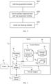
- FIG. 5 is a schematic diagram of a server according to some embodiments of the present disclosure.
- FIG. 5 is a block diagram of a server 12 for implementing embodiments of the present disclosure.
- the server 12 illustrated in FIG. 5 is only illustrated as an example, and should not be considered as any restriction on the function and the usage scope of embodiments of the present disclosure.
- the server 12 is in the form of a general-purpose computing device.
- the server 12 may include, but is not limited to, one or more processors or processing units 16, a system memory 28, and a bus 18 connecting different system components (including the system memory 28 and the processing unit 16).
- the bus 18 represents one or more of several types of bus architectures, including a memory bus or a memory control bus, a peripheral bus, a graphic acceleration port (GAP) bus, a processor bus, or a local bus using any bus architecture in a variety of bus architectures.
- these architectures include, but are not limited to, an industry standard architecture (ISA) bus, a microchannel architecture (MCA) bus, an enhanced ISA bus, a video electronic standards association (VESA) local bus, and a peripheral component interconnect (PCI) bus.
- ISA industry standard architecture
- MCA microchannel architecture
- VESA video electronic standards association
- PCI peripheral component interconnect
- the server 12 may include multiple kinds of computer-readable media. These media may be any storage media accessible by the server 12, including transitory or non-transitory storage medium and movable or unmovable storage medium.
- the memory 28 may include a computer-readable medium in a form of volatile memory, such as a random-access memory (RAM) 30 and/or a high-speed cache memory 32.
- the server 12 may further include other transitory/non-transitory storage media and movable/unmovable storage media.
- the storage system 34 may be configured to read and write non-removable, non-volatile magnetic media (not shown in the figure, commonly referred to as "hard disk drives").
- it may be provided a disk driver for reading and writing movable non-volatile magnetic disks (e.g. "floppy disks"), as well as an optical driver for reading and writing movable non-volatile optical disks (e.g.
- each driver may be connected to the bus 18 via one or more data medium interfaces.
- the memory 28 may include at least one program product, which has a set of (for example at least one) program modules configured to perform the functions of embodiments of the present disclosure.
- a program/application 40 with a set of (at least one) program modules 42 may be stored in memory 28, the program modules 42 may include, but not limit to, an operating system, one or more application programs, other program modules and program data, and any one or combination of above examples may include an implementation in a network environment.
- the program modules 42 are generally configured to implement functions and/or methods described in embodiments of the present disclosure.
- the server 12 may also communicate with one or more external devices 14 (e.g., a keyboard, a pointing device, a display 24, and etc.) and may also communicate with one or more devices that enables a user to interact with the computer system/server 12, and/or any device (e.g., a network card, a modem, and etc.) that enables the computer system/server 12 to communicate with one or more other computing devices. This kind of communication can be achieved by the input/output (I/O) interface 22.
- the server 12 may be connected to and communicate with one or more networks such as a local area network (LAN), a wide area network (WAN) and/or a public network such as the Internet through a network adapter 20.
- the network adapter 20 communicates with other modules of the server 12 over bus 18. It should be understood that although not shown in the figure, other hardware and/or software modules may be used in combination with the server 12, which including, but not limited to, microcode, device drivers, redundant processing units, external disk drive arrays, RAID systems, tape drives, as well as data backup storage systems and the like.
- the processing unit 16 can perform various functional applications and data processing by running programs stored in the system memory 28, for example, to perform the method according to embodiments of the present disclosure.
- the method includes: acquiring road lines of all branches at the intersection based on vector data of the intersection; performing a line-to-surface expansion based on the road lines to obtain road surfaces, and acquiring two side lines of each of the road surfaces; and determining target side line pairs based on side lines of the intersection, and drawing a corner arc at a corner of each of the target side line pairs.
- Each of the target side line pairs includes two side lines that do not belong to the same road line and are adjacent to each other.
- Embodiments of the present disclosure further provides a computer readable storage medium having a computer program stored thereon.
- the program When the program is executed by a processor, the processor is configured to implement the method according to embodiments of the present disclosure.
- the computer storage medium may adopt any combination of one or more computer readable media.
- the computer readable medium may be a computer readable signal medium or a computer readable storage medium.
- the computer readable storage medium may be, but is not limited to, for example, an electrical, magnetic, optical, electromagnetic, infrared, or semiconductor system, apparatus, device, component or any combination thereof.
- a specific example of the computer readable storage media include (a non-exhaustive list): an electrical connection having one or more wires, a portable computer disk, a hard disk, a random access memory (RAM), a read only memory (ROM), an Erasable Programmable Read Only Memory (EPROM) or a flash memory, an optical fiber, a compact disc read-only memory (CD-ROM), an optical memory component, a magnetic memory component, or any suitable combination thereof.
- the computer readable storage medium may be any tangible medium including or storing programs. The programs may be used by an instruction executed system, apparatus or device, or a connection thereof.
- the computer readable signal medium may include a data signal propagating in baseband or as part of carrier which carries a computer readable program code. Such propagated data signal may be in many forms, including but not limited to an electromagnetic signal, an optical signal, or any suitable combination thereof.
- the computer readable signal medium may also be any computer readable medium other than the computer readable storage medium, which may send, propagate, or transport programs used by an instruction executed system, apparatus or device, or a connection thereof.
- the program code stored on the computer readable medium may be transmitted using any appropriate medium, including but not limited to wireless, wireline, optical fiber cable, RF, or any suitable combination thereof.
- the computer program code for carrying out operations of embodiments of the present disclosure may be written in one or more programming languages.
- the programming language includes an object-oriented programming language, such as Java, Smalltalk, C ++, as well as conventional procedural programming language, such as "C" language or similar programming language.
- the program code may be executed entirely on a user's computer, partly on the user's computer, as a separate software package, partly on the user's computer, partly on a remote computer, or entirely on the remote computer or server.
- the remote computer may be connected to the user's computer or an external computer (such as using an Internet service provider to connect over the Internet) through any kind of network, including a Local Area Network (hereafter referred as to LAN) or a Wide Area Network (hereafter referred as to WAN).
- LAN Local Area Network
- WAN Wide Area Network
Description
- Embodiments of the present disclosure relate to the field of maps, and more particularly, to a method and a device for drawing an intersection, a server and a storage medium.
- With the development of intelligent terminals and Internet technologies, people's travel and navigation maps are becoming inseparable, and people's requirements for map clarity are becoming higher. Due to the complexity of roads, especially the crisscross intersections, the clarity and presentation of the road in the map play an important role in guiding people correctly.
-
US 2001/012981 A1 discloses an intersection display method, and a map display unit and a recording medium for realizing the method. -
US 2013/328916 A1 discloses smoothing road geometry. -
WO 2017/166687 A1 discloses a method and apparatus for generating three-dimensional intersection roadway model, and a storage medium. -
CN 109 297 501 A discloses a method for automatically generating dual line network by GIS single line network. -
CN 107 478 201A discloses a digital road acquisition method and device based on digital ortho-images. - According to a first aspect of the invention, a method according to
claim 1 is provided. - According to a second aspect of the invention, a device according to claim 9 is provided.
- According to a third aspect of the invention, a computer readable storage medium according to claim 13 is provided.
- With the method according to embodiments of the present disclosure, the road lines all branches at the intersection are obtained based on the vector data of the intersection, the road surfaces are acquired by line-to-surface expansion, and a rough intersection is drawn, and then by drawing the corner arc at the target side line pair, a fine intersection can be obtained, such that the high-definition intersection can be drawn quickly, the intersection can be drawn in fine detail, the costs of manual drawing can be reduced, the drawn intersection is close to the real world, and the accuracy of drawing the intersection can be improved.
-
-
FIG. 1a is a flowchart of a method for drawing an intersection according to some embodiments of the present disclosure. -
FIG. 1b is a schematic diagram illustrating road lines and road surfaces according to some embodiments of the present disclosure. -
FIG. 1c is a schematic diagram illustrating corner arcs according to some embodiments of the present disclosure. -
FIG. 2a is a flowchart of a method for drawing an intersection according to some embodiments of the present disclosure. -
FIG. 2b is a schematic diagram illustrating approximately parallel side lines according to some embodiments of the present disclosure. -
FIG. 3a is a flowchart of a method for drawing an intersection according to some embodiments of the present disclosure. -
FIG. 3b to FIG. 3e are schematic diagrams of determining control points of a Bezier curve function according to some embodiments of the present disclosure. -
FIG. 4 is a schematic diagram of a device for drawing an intersection according to some embodiments of the present disclosure. -
FIG. 5 is a schematic diagram of a server according to some embodiments of the present disclosure. - The present disclosure will be described in detail below with reference to the accompanying drawings and embodiments. It should be understood that, the embodiments described herein are only used to explain the present disclosure, rather than to limit the present disclosure. In addition, it should also be noted that, for convenience of description, only part but not all structures related to the present disclosure are illustrated in the accompanying drawings.
- In the related art, the high-definition intersection is generally drawn manually or by calculating a convex hull. Although the intersection drawn manually may be well presented, this manner requires the operator to have rich professional knowledge, be proficient in using drawing software, and this manner also has complex operations, long cycles, and slow update speeds, and for tens of millions of intersections, this manner is difficult to deal with quickly. Although the convex hull calculation method is simple to realize and can quickly construct a simple intersection, this manner has poor presentation effect, which is far from the actual intersection shape.
-
FIG. 1a is a flowchart of a method for drawing an intersection according to some embodiments of the present disclosure. The embodiment may be applied to the case of drawing a high-definition intersection. The method may be performed by a device for drawing an intersection, and the device may be implemented by software and/or hardware, and be configured in a server. As shown inFIG. 1a , the method may include the following operations. - At block S101, road line of all branches at the intersection are acquired based on vector data of the intersection.
- The raw data of the base map may include vector data of the intersection, which includes line data and line relationship data of any intersection, and records the road line of each of the branches at the intersection and the intersection point of each road line, and the road lines of all branches at the intersection can be acquired according to the line data and the line relationship data. In some actual application scenarios, an N table is generally configured to represent the line relationship. The N table records coordinates of the feature point N of the intersection, i.e., the intersection point of respective road lines, and road segment data of all branches associated with the feature point N at the intersection, i.e., the road line. Illustratively, the feature point N may be the center point of the intersection.
- At block S102, a line-to-surface expansion is performed based on the road lines to obtain road surfaces, and two side lines of each of the road surfaces are obtained.
- Since the roads at actual intersections are surfaces rather than lines, it is necessary to convert the line data into surface data, the line-to-surface expansion may be performed based on each road line to obtain the road surfaces of all branches at the intersection. In each road surface, the two sides parallel to the road line are the side lines, and each road surface has two side lines.
- In some embodiments, the line-to-surface expansion may include acts of: based on each road line, expanding to both sides of the road line by taking an intersection width as the expansion distance, to obtain the two side lines of each of the road surfaces of all branches at the intersection. In an example, the feature point N is the center point of the intersection, and the road line is the center line of the branch, thus expansion to both sides of the center line may be performed by taking each road line as the center line and half of the intersection width as the expansion distance, and road surfaces of all branches at the intersection may be obtained. The expansion distance to the both sides of the center line may be a distance of other lengths determined according to the intersection width, which is not limited in the present disclosure.
-
FIG. 1b is a schematic diagram illustrating road lines and road surfaces according to some embodiments of the present disclosure, as shown inFIG. 1b , the point N is the center point of the intersection, four lines a, b, c, and d are four road lines of four branches, and S1, S2, S3 and S4 are four road surfaces obtained by line-to-surface expansion. The side lines of the road surface S1 include a1 and a2, the side lines of the road surface S2 include b1 and b2, the side lines of the road surface S3 include c1 and c2, and the side lines of the road surface S4 include d1 and d2. - At block S103, target side line pairs are determined based on side lines of the intersection, and a corner arc is drawn at the corner of each of the target side line pairs.
- In some embodiments, each of the target side line pairs may include two side lines that do not belong to the same road line and are adjacent to each other. In actual intersections, most corners of two adjacent branches are not right angles, and are arc, thus the two side lines that need to draw the arc needs to be found based on the road surfaces, and the corner arc needs to be drawn at the corner of each target side line pair. The two side lines in the target side line pair that needs to draw the corner arc belong to different road lines and are adjacent to each other. In an example, as illustrated in
FIG. 1b , taking the road line as the center line, a2 and b1, b2 and c1, c2 and d1, and d2 and a1 are four target side line pairs. - In some embodiments of the present disclosure, the corner arc may be drawn by, for example, an arc function, a five-point smoothing method, a spline interpolation method, or a linear fitting method, and the complexity and effect of different methods may be different. In an example, a Bezier curve function may be used to draw the corner arc, the Bezier curve may ensure that the drawn arc is tangent to the side line with as few interpolation points as possible, the smooth transition effect may be implemented by using the Bezier curve function. Illustratively,
FIG. 1c is a schematic diagram illustrating corner arcs according to some embodiments of the present disclosure, as shown inFIG. 1c , taking the road line as the center line as an example, m1, m2, m3 and m4 are four corner arcs drawn. - In some embodiments, the method further includes: drawing, according to the vector data, a road convex hull based on the road surfaces of the intersection by using a convex hull method. In the road convex hull, the road corner is represented by a straight line. After the corner arc at the corner of the target side line pair is drawn, the method further includes: replacing the straight line in the road convex hull with the corner arc.
- The convex hull method such as Graham scan method or Jarvis stepping method may realize enclosing all the determined points with a convex polygon. In drawing the intersection, the convex hull method may be configured to draw a simple intersection, the corner of the road is represented by the straight line in the simple intersection, and the actual situation of the intersection cannot be presented. It should be noted that, due to the imperfection of basic road vector data, the road line and the road surface may not be obtained based on the vector data, and it may be impossible to ensure that the corner arc can be drawn at the corners of all target side line pairs. By drawing the simple intersection using the convex hull method, and replacing the straight line at the corner in the road convex hull with the corner arc drawn, the problem of missing partial intersection when the corner arc cannot be drawn using the vector data can be avoided, thereby ensuring the integrity of the intersection drawn.
- With the method according to embodiments of the present disclosure, the road lines all branches at the intersection are obtained based on the vector data of the intersection, the road surfaces are acquired by line-to-surface expansion, and a rough intersection is drawn, and then by drawing the corner arc at the target side line pair, a fine intersection can be obtained, such that the high-definition intersection can be drawn quickly, the intersection can be drawn in fine detail, the costs of manual drawing can be reduced, the drawn intersection is close to the real world, and the accuracy of drawing the intersection can be improved.
-
FIG. 2a is a flowchart of a method for drawing an intersection according to an embodiment of the invention. The embodiment is on the basis of the above embodiments. As shown inFIG. 2a , the method includes the following acts. - At block S201, road lines of all branches at the intersection are acquired based on vector data of the intersection.
- At block S202, a line-to-surface expansion is performed based on the road lines to obtain road surfaces, and two side lines of each of the road surfaces are obtained.
- At block S203, a binding relationship between the two side lines of each road surface and the road line is recorded, and a position relationship between respective side lines and the road line to which the side line belongs is recorded, the position relationship includes being located on left or right of the road line.
- In order to determine the target side line pair that needs to draw the corner arc, and prevent from drawing the corner arc at the two side lines expanded from the same road, after the road surface is determined, the binding relationship between the two side lines of each road surface and the road line is recorded. In an example, the binding relationship includes the relationship between each road line and its left and right side lines. Illustratively, as shown in
FIG. 1b , taking the road line being the center line as an example, it is recorded that the center line of the side line a1 and a2 is a, the side line a1 is located on the left side of the center line a, the side line a2 is located on the right side of the center line a. By analogy, the center line b, c, d and the corresponding binding relationship can be obtained. - At block S204, road line vectors of all branches at the intersection are determined according to the vector data, and an included angle of each of the road line vectors with respect to a preset direction of a preset coordinate axis is calculated.
- In an example, the preset direction includes a positive direction and a negative direction.
- At block S205, the road lines are sorted according to the included angles to obtain a road line order.
- The relationship between the road line and the side lines is obtained at block 203, and it is also determined whether the side line is located on the left or right side of the road line, thus the sorting of the side lines may be determined by the sorting of the road lines, and then based on the order of the road lines obtained and the positional relationship between the side lines and the road lines, the order of the side lines can be obtained.
- In an example, the road line vectors of all branches at the intersection are determined according to the vector data of the road, and the included angle of each of the road line vectors with respect to the preset direction of the preset coordinate axis is determined. The preset direction includes a positive direction and a negative direction. Illustratively, as shown in
FIG. 1b , as an example, the road line is the center line, xy axis is the preset coordinate axis, x axis is the horizontal axis, the y axis is the vertical axis, and the positive direction of the x axis is the preset direction. By calculation, it may be obtained that the included angle between the center line c and the positive direction of x axis is 0, the included angle between the center line b and the positive direction of x axis is 90, the included angle between the center line a and the positive direction of x axis is 180, and the included angle between the center line d and the positive direction of x axis is 270, when it is sorted based on the sizes of the included angles in an ascending order, the order of the center lines in a counterclockwise manner, i.e., c b, a, and d, may be obtained - At block S206, according to the position relationship and the road line order, the side lines are sorted in a clockwise or counterclockwise direction to obtain the side line order.
- In the above example, as shown in
Fig. 1b , when the position relationship between each side line and the center lines is known, the side line order c2, c1, b2, b1, a2, a1, d2 and d1 may be obtained according to the center line order c, b, a, d. - At block S207, the target side line pairs are determined according to the side line order and the binding relationship.
- Further, in the above example, as shown in
Fig. 1b , according to the side line order and the binding relationship, all target side line pairs, including c1 and b2, b1 and a2, a1 and d2, and d1 and c2, can be determined. - It should be noted that, after the included angle of each road line vector with respect to the preset direction of the preset coordinate axis is determined, it may be sorted in a descending order (from high to low) or ascending order (from low to high) of the included angles. In addition, the coordinate axis may be determined according to actual requirements, which is not limited in embodiments of the present disclosure.
- At block S208, the corner arc is drawn at the corner of each of the target side line pairs.
- In an example, there is a case where the two side lines are approximately parallel, for example, the included angle between a main road and a side road is small, and the main road is approximately parallel to the side road. In this case, when it is sorted according to the included angles, there may be errors. Illustratively,
FIG. 2b is a schematic diagram illustrating approximately parallel side lines according to some embodiments of the present disclosure, as shown inFIG. 2b , the side lines L1 and L2 are approximately parallel, when the positive direction of the horizontal axis is the preset direction of the preset coordinate axis, according to the above method, it may be determined that the included angle corresponding to the side line L2 is less than the included angle corresponding to the side line L1. When it is sorted in the ascending order of the included angles, order of the side lines in the counterclockwise manner is L2, L1. However, the actual order of the side lines in the counterclockwise manner is L1, L2, an error occurs, and it is required to correct. - In an example, determining the target side line pair according to the side line order and the binding relationship (block S207) further includes acts of: determining whether there are at least two parallel side lines in the side lines according to a preset angle threshold; in any two target parallel side lines, selecting a target point on one of the two target parallel side lines, and determining a target position relationship between the target point and the other of the two target parallel side lines by using a cross product method; correcting the side line order according to the target position relationship; and determining the target side line pairs according to the side line order corrected and the binding relationship.
- In an example, the order of two approximately parallel side lines is corrected. After all the side line pairs are obtained, at least two parallel side lines, such as L2 and L1 in
FIG. 2b , in the side lines may be determined according to the preset angle threshold. The preset angle threshold may be configured to determine the intersection or parallel of the side lines. A point K on the side line L2 is taken as the target point, a vector product of the point K and the side line L1 can be calculated by using the cross product method, and the target position relationship between the target point K and the side line L1 may be determined according to the calculation result. InFIG. 2b , the point K is located on the left side of the side line L1. When the determined order of the side lines in the counterclockwise manner is L2, L1, any point on the side line L2 should be at the right side of the side line L1. Thus, it may be determined that the determined order does not match the actual result, and then the order of the side lines may be corrected according to the target position relationship. - After correction, the target side line pairs may be determined according to the side line order corrected and the binding relationship, such that the target side line pair that needs to draw the corner arc may be accurately determined, and the accuracy of drawing the intersection can be improved.
- With the method according to embodiments of the present disclosure, the road lines all branches at the intersection are obtained based on the vector data of the intersection, the road surfaces are acquired by line-to-surface expansion, and a rough intersection is drawn, and then by drawing the corner arc at the target side line pair, a fine intersection can be obtained, such that the high-definition intersection can be drawn quickly, the intersection can be drawn in fine detail, the costs of manual drawing can be reduced, the drawn intersection is close to the real world. Moreover, in the process of determining the target side line pairs that needs to draw the corner arc, by sorting and then correcting the order of the side lines determined, the accuracy of the order of the side lines determined can be improved, and the accuracy of drawing the intersection can be improved.
-
FIG. 3a is a flowchart of a method for drawing an intersection according to some embodiments of the present disclosure. The embodiment is on the basis of the above embodiments. As shown inFIG. 3a , the method includes the following operations. - At block S301, road lines of all branches at the intersection are acquired based on vector data of the intersection.
- At block S302, a line-to-surface expansion is performed based on the road lines to obtain road surfaces, and two side lines of each of the road surfaces are obtained.
- At block S303, target side line pairs are determined based on side lines of the intersection.
- In some embodiments, each target side line pair includes two side lines that do not belong to the same road line and are adjacent to each other.
- At block S304, the corner arc is drawn at the corner of each of the target side line pairs by using a Bezier curve function.
- In an example, drawing the corner arc at the corner of each of the side line pairs by using the Bezier curve function includes acts of: for a non-parallel side line pair, drawing the corner arc by using a second-order Bezier curve function; and for a parallel side line pair, drawing the corner arc by using a third-order Bezier curve function.
- In an example, whether a side line pair is the parallel side line pair or the non-parallel side line pair is determined according to a preset angle threshold. The parallel side line pair may refer to a side line pair including two side lines that are parallel. The non-parallel side line pair may refer to a side line pair including two side lines that are not parallel.
- In an example, drawing the corner arc at the corner of each of the side line pairs by using the Bezier curve function further includes acts of: according to the vector data, drawing the corner arc at the corner of a target side line pair by using the third-order Bezier curve function, when the two side lines in the target side line pair intersect in a direction away from a center of the intersection to which the target side line pair belongs.
- In some embodiments of the present disclosure, different conditions of the side line pairs are considered, and the corner arc is drawn by using the Bezier curve function with different orders. For the non-parallel side line pair, the corner arc is drawn by using the second-order Bezier curve function, and for the parallel side line pair, the corner arc is drawn by using the third-order Bezier curve function. It should be noted that, in actual road conditions, the parallel side lines here may refer to approximately parallel, i.e., the parallel of two side lines is determined according to the preset angle threshold, when the included angle of two side lines is less than the preset angle threshold, it is determined that the two side lines are parallel, and they belong to the parallel side line pair. For a particular side line pair, i.e., the two side lines in this side line pair intersect in the direction away from the center of the intersection to which the side line pair belongs, the corner arc is drawn at the corner of the side line pair by using the third-order Bezier curve function. Although the two side lines in the particular side line pair are approximately parallel, when it is determined whether there is the parallel side line pair by using the preset angle threshold, in reality, some approximately parallel side line pairs may be missed due to inaccuracy of the raw vector data, thus it is necessary to select, according to the characteristics of the side line pairs, the particular side line pair that also needs to draw the corner arc by using the third-order Bezier curve function, so as to improve the accuracy.
- In an example, control points of the second-order Bezier curve function include an intersection point of each target side line pair, and foot points of an offset point on respective side lines in each target side line pair. The offset point is on the road line to which the target side line pair belongs. The control points of the third-order Bezier curve function include end points on the target side line pair close to the intersection to which the target side line pair belongs, and the foot points of the offset points on road line to which the target side line pair belongs on respective side lines in the target side line pair. The offset point is on the road line to which the target side line pair belongs.
- In an example, the offset point is determined by acts of: obtaining an intersection surface of the road surfaces to which the two side lines in the target side line pair belongs, and obtaining an intersection point of the road lines to which the target side line pair belongs; determining, from all points on the intersection surface, a point having a maximum distance to the intersection point of the road lines; calculating a sum of the distance and a preset threshold as an offset length; and on the road lines to which the target side line pair belongs, determining a point at the offset length from the intersection point as the offset point.
- Specifically, as an example, the feature point N is the center point of the intersection, and the road line is the center line, as shown in
FIG. 3b , the intersection surface of the road surfaces S1 and S2 is S', and the intersection point of the road lines to which the target side line pair belongs is the center point N. In the intersection surface S', the point N' has the maximum distance to the intersection point N, and the distance between N' and N is denoted as dis. As shown inFIG. 3c , the offset length can be obtained by adding disc and a preset threshold delta (an experience value), and on the center lines a, b, c and d, the points p1, p2, p3 and p4 at the offset length away from the center point N are four offset points. The points z1 and z2 are foot points of the offset point p1 on respective side lines of the center line a, and the foot points of other offset points on their respective center lines are not shown inFIG. 3c . - In addition, the feature point N is the center point of the intersection, and the road line is the center line,
FIG. 3d illustrates control points of a second-order Bezier curve function, andFIG. 3e illustrates control points of a third-order Bezier curve function. As shown inFIG. 3d , the control points of the second-order Bezier curve function may include the intersection point C of the side line pair a2 and b1, and the foot points z2, z3, in which z2 is the foot point of the offset point p1 on the center line a to which the side line pair belongs, z3 is the foot point of the offset point p2 on the center line b to which the side line pair belongs. As shown inFIG. 3e , the control points of the third-order Bezier curve function include the end points C1, C2 on the side line pair close to the intersection to which the side line pair belongs, and the foot points z2 and z3. - With the method according to embodiments of the present disclosure, the road lines all branches at the intersection are obtained based on the vector data of the intersection, the road surfaces are acquired by line-to-surface expansion, and a rough intersection is drawn, and then by drawing the corner arc at the target side line pair, a fine intersection can be obtained, such that the high-definition intersection can be drawn quickly, the intersection can be drawn in fine detail, the costs of manual drawing can be reduced, the drawn intersection is close to the real world, and the accuracy of drawing the intersection can be improved.
-
FIG. 4 is a schematic diagram of a device for drawing an intersection according to some embodiments of the present disclosure. As shown inFIG. 4 , the device includes: a roadline acquisition module 410, a line-to-surface expansion and sideline acquisition module 420, and a cornerarc drawing module 430. - The road
line acquisition module 410 is configured to acquire road lines of all branches at the intersection based on vector data of the intersection. The line-to-surface expansion and sideline acquisition module 420 is configured to perform a line-to-surface expansion according to the road lines to obtain road surfaces, and acquire two side lines of each of the road surfaces. The cornerarc drawing module 430 is configured to target side line pairs based on side lines of the intersection, and draw a corner arc at a corner of each of the target side line pairs. Each of the target side line pairs includes two side lines that do not belong to the same road line and are adjacent to each other. - In at least one embodiment, the line-to-surface expansion and side
line acquisition module 420 is further configured to: based on each road line, expand to both sides of the road line by taking an intersection width as an expansion distance, to obtain the two side lines of each of the road surfaces of all branches at the intersection. The device further includes a recording module. The recording module is configured to record a binding relationship between the two side lines of each of the road surfaces and the road line, and record a position relationship between respective side lines and the road line to which the side line belongs. The position relationship includes being located on left or right of the road line - The corner
arc drawing module 430 includes a side line pair determining unit. The side line pair determining unit includes an included angle calculation subunit, a center line order determining subunit, a side line order determining subunit, and a side line pair determining subunit. - The included angle calculation subunit is configured to determine road line vectors of all the branches at the intersection according to the vector data, and calculate an included angle of each of the road line vectors with respect to a preset direction of a preset coordinate axis. The preset direction includes a positive direction and a negative direction. The center line order determining subunit is configured to sort the road lines according to the included angles to obtain a road line order. The side line order determining subunit is configured to sort, according to the position relationship and the road line order, the side lines in a clockwise or counterclockwise manner to obtain a side line order. The side line pair determining subunit is configured to determine the target side line pairs according to the side line order and the binding relationship.
- In at least one embodiment, the side line pair determining subunit is further configured to determine whether there are at least two parallel side lines according to a preset angle threshold; in any two target parallel side lines, select a target point on one of the two target parallel side lines, and determine a target position relationship between the target point and the other of the two target parallel side lines by using a cross product method; correct the side line order according to the target position relationship; and determine the target side line pairs according to the side line order corrected and the binding relationship.
- In at least one embodiment, the corner
arc drawing module 430 includes a corner drawing unit, which is configured to draw the corner arc at the corner of each of the target side line pairs by using a Bezier curve function. - In at least one embodiment, the corner drawing unit includes: a first corner drawing unit and a second corner drawing unit. The first corner drawing unit is configured to, for a non-parallel side line pair, draw the corner arc by using a second-order Bezier curve function. The second corner drawing unit is configured to, for a parallel side line pair, draw the corner arc by using a third-order Bezier curve function.
- In some embodiments, whether a side line pair is the parallel side line pair or the non-parallel side line pair is determined according to a preset angle threshold.
- In at least one embodiment, the corner drawing unit further includes a third corner drawing unit. The third corner drawing unit is configured to, according to the vector data, draw the corner arc at the corner of a target side line pair by using the third-order Bezier curve function, when the two side lines in the target side line pair intersect in a direction away from a center of the intersection to which the target side line pair belongs.
- In at least one embodiment, control points of the second-order Bezier curve function include an intersection point of each target side line pair, and foot points of an offset point on respective side lines in each target side line pair. The offset point is on the road line to which the target side line pair belongs. The control points of the third-order Bezier curve function include end points on the target side line pair close to the intersection to which the target side line pair belongs, and the foot points of the offset points on road line to which the target side line pair belongs on respective side lines in the target side line pair. The offset point is on the road line to which the target side line pair belongs.
- In at least one embodiment, the offset point is determined by acts of: obtaining an intersection surface of the road surfaces to which the two side lines in the target side line pair belongs, and obtaining an intersection point of the road lines to which the target side line pair belongs; determining, from all points on the intersection surface, a point having a maximum distance to the intersection point of the road lines; calculating a sum of the distance and a preset threshold as an offset length; and on the road lines to which the target side line pair belongs, determining a point at the offset length from the intersection point as the offset point.
- In at least one embodiment, the device further includes a road convex hull drawing module, and a corner arc replacing module.
- The road convex hull drawing module is configured to draw, according to the vector data, a road convex hull based on the road surfaces by using a convex hull method. In the road convex hull, a road corner is represented by a straight line. The corner arc replacing module is configured to, after the corner
arc drawing module 430 draws the corner arc at the corner of each of the target side line pairs, replace the straight line in the road convex hull with the corner arc. - The device for drawing an intersection according to embodiments of the present disclosure may perform the method for drawing an intersection according to any embodiment of the present disclosure, and has functional modules for executing the method and beneficial effects.
-
FIG. 5 is a schematic diagram of a server according to some embodiments of the present disclosure.FIG. 5 is a block diagram of aserver 12 for implementing embodiments of the present disclosure. Theserver 12 illustrated inFIG. 5 is only illustrated as an example, and should not be considered as any restriction on the function and the usage scope of embodiments of the present disclosure. - As illustrated in
FIG. 5 , theserver 12 is in the form of a general-purpose computing device. Theserver 12 may include, but is not limited to, one or more processors orprocessing units 16, asystem memory 28, and abus 18 connecting different system components (including thesystem memory 28 and the processing unit 16). - The
bus 18 represents one or more of several types of bus architectures, including a memory bus or a memory control bus, a peripheral bus, a graphic acceleration port (GAP) bus, a processor bus, or a local bus using any bus architecture in a variety of bus architectures. For example, these architectures include, but are not limited to, an industry standard architecture (ISA) bus, a microchannel architecture (MCA) bus, an enhanced ISA bus, a video electronic standards association (VESA) local bus, and a peripheral component interconnect (PCI) bus. - Typically, the
server 12 may include multiple kinds of computer-readable media. These media may be any storage media accessible by theserver 12, including transitory or non-transitory storage medium and movable or unmovable storage medium. - The
memory 28 may include a computer-readable medium in a form of volatile memory, such as a random-access memory (RAM) 30 and/or a high-speed cache memory 32. Theserver 12 may further include other transitory/non-transitory storage media and movable/unmovable storage media. In way of example only, thestorage system 34 may be configured to read and write non-removable, non-volatile magnetic media (not shown in the figure, commonly referred to as "hard disk drives"). Although not illustrated inFIG. 5 , it may be provided a disk driver for reading and writing movable non-volatile magnetic disks (e.g. "floppy disks"), as well as an optical driver for reading and writing movable non-volatile optical disks (e.g. a compact disc read only memory (CD-ROM, a digital video disc read only Memory (DVD-ROM), or other optical media). In these cases, each driver may be connected to thebus 18 via one or more data medium interfaces. Thememory 28 may include at least one program product, which has a set of (for example at least one) program modules configured to perform the functions of embodiments of the present disclosure. - A program/
application 40 with a set of (at least one)program modules 42 may be stored inmemory 28, theprogram modules 42 may include, but not limit to, an operating system, one or more application programs, other program modules and program data, and any one or combination of above examples may include an implementation in a network environment. Theprogram modules 42 are generally configured to implement functions and/or methods described in embodiments of the present disclosure. - The
server 12 may also communicate with one or more external devices 14 (e.g., a keyboard, a pointing device, adisplay 24, and etc.) and may also communicate with one or more devices that enables a user to interact with the computer system/server 12, and/or any device (e.g., a network card, a modem, and etc.) that enables the computer system/server 12 to communicate with one or more other computing devices. This kind of communication can be achieved by the input/output (I/O)interface 22. In addition, theserver 12 may be connected to and communicate with one or more networks such as a local area network (LAN), a wide area network (WAN) and/or a public network such as the Internet through anetwork adapter 20. As shown in Fig.9, thenetwork adapter 20 communicates with other modules of theserver 12 overbus 18. It should be understood that although not shown in the figure, other hardware and/or software modules may be used in combination with theserver 12, which including, but not limited to, microcode, device drivers, redundant processing units, external disk drive arrays, RAID systems, tape drives, as well as data backup storage systems and the like. - The
processing unit 16 can perform various functional applications and data processing by running programs stored in thesystem memory 28, for example, to perform the method according to embodiments of the present disclosure. The method includes: acquiring road lines of all branches at the intersection based on vector data of the intersection; performing a line-to-surface expansion based on the road lines to obtain road surfaces, and acquiring two side lines of each of the road surfaces; and determining target side line pairs based on side lines of the intersection, and drawing a corner arc at a corner of each of the target side line pairs. Each of the target side line pairs includes two side lines that do not belong to the same road line and are adjacent to each other. - Embodiments of the present disclosure further provides a computer readable storage medium having a computer program stored thereon. When the program is executed by a processor, the processor is configured to implement the method according to embodiments of the present disclosure.
- The computer storage medium may adopt any combination of one or more computer readable media. The computer readable medium may be a computer readable signal medium or a computer readable storage medium. The computer readable storage medium may be, but is not limited to, for example, an electrical, magnetic, optical, electromagnetic, infrared, or semiconductor system, apparatus, device, component or any combination thereof. A specific example of the computer readable storage media include (a non-exhaustive list): an electrical connection having one or more wires, a portable computer disk, a hard disk, a random access memory (RAM), a read only memory (ROM), an Erasable Programmable Read Only Memory (EPROM) or a flash memory, an optical fiber, a compact disc read-only memory (CD-ROM), an optical memory component, a magnetic memory component, or any suitable combination thereof. In context, the computer readable storage medium may be any tangible medium including or storing programs. The programs may be used by an instruction executed system, apparatus or device, or a connection thereof.
- The computer readable signal medium may include a data signal propagating in baseband or as part of carrier which carries a computer readable program code. Such propagated data signal may be in many forms, including but not limited to an electromagnetic signal, an optical signal, or any suitable combination thereof. The computer readable signal medium may also be any computer readable medium other than the computer readable storage medium, which may send, propagate, or transport programs used by an instruction executed system, apparatus or device, or a connection thereof.
- The program code stored on the computer readable medium may be transmitted using any appropriate medium, including but not limited to wireless, wireline, optical fiber cable, RF, or any suitable combination thereof.
- The computer program code for carrying out operations of embodiments of the present disclosure may be written in one or more programming languages. The programming language includes an object-oriented programming language, such as Java, Smalltalk, C ++, as well as conventional procedural programming language, such as "C" language or similar programming language. The program code may be executed entirely on a user's computer, partly on the user's computer, as a separate software package, partly on the user's computer, partly on a remote computer, or entirely on the remote computer or server. In a case of the remote computer, the remote computer may be connected to the user's computer or an external computer (such as using an Internet service provider to connect over the Internet) through any kind of network, including a Local Area Network (hereafter referred as to LAN) or a Wide Area Network (hereafter referred as to WAN).
Claims (13)
- A computer-implemented method for drawing an intersection, comprising:acquiring road lines of all branches at the intersection based on vector data of the intersection (S101, S201, S301);performing a line-to-surface expansion based on the road lines to obtain road surfaces, and acquiring two side lines of each of the road surfaces (S102, S202, S302); anddetermining target side line pairs based on side lines of the intersection, and drawing a corner arc at a corner of each of the target side line pairs (S103, S208, S303), wherein each of the target side line pairs comprises two side lines that do not belong to the same road line and are adjacent to each other;characterized in that the method further comprises:recording a binding relationship between the two side lines of each of the road surfaces and the road line, and recording a position relationship between respective side lines and the road line to which the side line belongs (S203), wherein the position relationship comprises being located on left or right of the road line,wherein determining the target side line pairs (S103, S208, S303) comprises:determining road line vectors of all the branches at the intersection according to the vector data, and calculating an included angle of each of the road line vectors with respect to a preset direction of a preset coordinate axis (S204), wherein the preset direction comprises a positive direction and a negative direction;sorting the road lines according to the included angles to obtain a road line order (S205);sorting, according to the position relationship and the road line order, the side lines in a clockwise or counterclockwise manner to obtain a side line order (S206); anddetermining the target side line pairs according to the side line order and the binding relationship (S207).
- The method according to claim 1, wherein performing the line-to-surface expansion based on the road lines to obtain the road surfaces and acquiring the two side lines of each of the road surfaces (S102, S202, S302) comprises:
based on each road line, expanding to both sides of the road line by taking an intersection width as an expansion distance, to obtain the two side lines of each of the road surfaces of all branches at the intersection. - The method according to claim 1, wherein determining the target side line pairs according to the side line order and the binding relationship (S207) comprises:determining whether there are at least two parallel side lines according to a preset angle threshold;in any two target parallel side lines, selecting a target point on one of the two target parallel side lines, and determining a target position relationship between the target point and the other of the two target parallel side lines by using a cross product method;correcting the side line order according to the target position relationship; anddetermining the target side line pairs according to the side line order corrected and the binding relationship.
- The method according to any one claims 1 to 3, wherein drawing the corner arc at the corner of each of the target side line pairs (S103, S208, S303) comprises:
drawing the corner arc at the corner of each of the target side line pairs by using a Bezier curve function (S304). - The method according to claim 4, wherein drawing the corner arc at the corner of each of the target side line pairs by using the Bezier curve function (S304) comprises:for a non-parallel side line pair, drawing the corner arc by using a second-order Bezier curve function; andfor a parallel side line pair, drawing the corner arc by using a third-order Bezier curve function;wherein whether a side line pair is the parallel side line pair or the non-parallel side line pair is determined according to a preset angle threshold.
- The method according to claim 4, wherein drawing the corner arc at the corner of each of the target side line pairs by using the Bezier curve function (S304) comprises:
according to the vector data, drawing the corner arc at the corner of a target side line pair by using the third-order Bezier curve function, when the two side lines in the target side line pair intersect in a direction away from a center of the intersection to which the target side line pair belongs. - The method according to any one of claims 4 to 6, wherein,control points of the second-order Bezier curve function comprise an intersection point of each target side line pair, and foot points of an offset point on respective side lines in each target side line pair, wherein the offset point is on the road line to which the target side line pair belongs;control points of the third-order Bezier curve function comprise end points on the target side line pair close to the intersection to which the target side line pair belongs, and the foot points of the offset points on road line to which the target side line pair belongs on respective side lines in the target side line pair, wherein the offset point is on the road line to which the target side line pair belongs;wherein the offset point is determined by acts of:obtaining an intersection surface of the road surfaces to which the two side lines in the target side line pair belongs, and obtaining an intersection point of the road lines to which the target side line pair belongs;determining, from all points on the intersection surface, a point having a maximum distance to the intersection point of the road lines;calculating a sum of the distance and a preset threshold as an offset length; andon the road lines to which the target side line pair belongs, determining a point at the offset length from the intersection point as the offset point.
- The method according to any one of claims 1 to 7, further comprising:drawing, according to the vector data, a road convex hull based on the road surfaces by using a convex hull method, wherein in the road convex hull, a road corner is represented by a straight line; andwherein after drawing the corner arc at the corner of each of the target side line pairs, the method further comprises:
replacing the straight line in the road convex hull with the corner arc. - A device for drawing an intersection, comprising:a road line acquisition module (410), configured to acquire road lines of all branches at the intersection based on vector data of the intersection;a line-to-surface expansion and side line acquisition module (420), configured to perform a line-to-surface expansion according to the road lines to obtain road surfaces, and acquire two side lines of each of the road surfaces; anda corner arc drawing module (430), configured to determine target side line pairs based on side lines of the intersection, and draw a corner arc at a corner of each of the target side line pairs, wherein each of the target side line pairs comprises two side lines that do not belong to the same road line and are adjacent to each other;characterized in that the device further comprises:a recording module, configured to record a binding relationship between the two side lines of each of the road surfaces and the road line, and record a position relationship between respective side lines and the road line to which the side line belongs, wherein the position relationship comprises being located on left or right of the road line,wherein the corner arc drawing module (430) comprises a side line pair determining unit, and the side line pair determining unit comprises:an included angle calculation subunit, configured to determine road line vectors of all the branches at the intersection according to the vector data, and calculate an included angle of each of the road line vectors with respect to a preset direction of a preset coordinate axis, wherein the preset direction comprises a positive direction and a negative direction;a center line order determining subunit, configured to sort the road lines according to the included angles to obtain a road line order;a side line order determining subunit, configured to sort, according to the position relationship and the road line order, the side lines in a clockwise or counterclockwise manner to obtain a side line order; anda side line pair determining subunit, configured to determine the target side line pairs according to the side line order and the binding relationship.
- The device according to claim 9, wherein the line-to-surface expansion and side line acquisition module (420) is further configured to:
based on each road line, expand to both sides of the road line by taking an intersection width as an expansion distance, to obtain the two side lines of each of the road surfaces of all branches at the intersection. - The device according to claim 9, wherein the side line pair determining subunit is further configured to:determine whether there are at least two parallel side lines according to a preset angle threshold;in any two target parallel side lines, select a target point on one of the two target parallel side lines, and determine a target position relationship between the target point and the other of the two target parallel side lines by using a cross product method;correct the side line order according to the target position relationship; anddetermine the target side line pairs according to the side line order corrected and the binding relationship.
- The device according to claim 9, wherein the corner arc drawing module (430) comprises:
a corner drawing unit, configured to draw the corner arc at the corner of each of the target side line pairs by using a Bezier curve function. - A computer readable storage medium having a computer program stored thereon, wherein when the program is executed by a processor, causes the method for drawing an intersection according to any one of claims 1 to 8 to be implemented.
Applications Claiming Priority (1)
| Application Number | Priority Date | Filing Date | Title |
|---|---|---|---|
| CN201910239884.9A CN109949389A (en) | 2019-03-27 | 2019-03-27 | A kind of crossing method for drafting, device, server and storage medium |
Publications (2)
| Publication Number | Publication Date |
|---|---|
| EP3715792A1 EP3715792A1 (en) | 2020-09-30 |
| EP3715792B1 true EP3715792B1 (en) | 2022-03-02 |
Family
ID=67012067
Family Applications (1)
| Application Number | Title | Priority Date | Filing Date |
|---|---|---|---|
| EP20165079.3A Active EP3715792B1 (en) | 2019-03-27 | 2020-03-24 | Method and device for drawing intersection |
Country Status (5)
| Country | Link |
|---|---|
| US (1) | US11120587B2 (en) |
| EP (1) | EP3715792B1 (en) |
| JP (1) | JP6966588B2 (en) |
| KR (1) | KR102293479B1 (en) |
| CN (1) | CN109949389A (en) |
Families Citing this family (15)
| Publication number | Priority date | Publication date | Assignee | Title |
|---|---|---|---|---|
| CN110617827B (en) * | 2019-08-23 | 2021-12-24 | 百度在线网络技术(北京)有限公司 | Main and auxiliary road drawing method and device, server and storage medium |
| CN112774197A (en) * | 2019-11-06 | 2021-05-11 | 网易(杭州)网络有限公司 | Road transition section generation method and device, electronic equipment and storage medium |
| CN113012255B (en) * | 2019-12-19 | 2024-01-09 | 百度在线网络技术(北京)有限公司 | Road edge extraction method, device, equipment and medium |
| CN111209360B (en) * | 2019-12-31 | 2022-08-23 | 武汉中海庭数据技术有限公司 | Method and system for automatically extracting road surface |
| CN113160693B (en) * | 2020-01-22 | 2022-09-09 | 百度在线网络技术(北京)有限公司 | Road intersection processing method, device, equipment and storage medium |
| CN111540026A (en) * | 2020-03-24 | 2020-08-14 | 北京三快在线科技有限公司 | Dynamic line drawing method and device, electronic equipment and storage medium |
| CN111739043B (en) * | 2020-04-13 | 2023-08-08 | 北京京东叁佰陆拾度电子商务有限公司 | Parking space drawing method, device, equipment and storage medium |
| CN112182722A (en) * | 2020-10-15 | 2021-01-05 | 洛阳众智软件科技股份有限公司 | Intelligent generation method, device and equipment of three-dimensional road model |
| CN112487117A (en) * | 2020-11-27 | 2021-03-12 | 新奥数能科技有限公司 | Method and device for determining intersection point of earth surface, readable medium and electronic equipment |
| CN112734879A (en) * | 2021-01-05 | 2021-04-30 | 卓望数码技术(深圳)有限公司 | Device, method, terminal and storage medium for drawing intersecting line cross curve |
| CN112530013B (en) * | 2021-02-09 | 2021-05-25 | 腾讯科技(深圳)有限公司 | Intersection region determination method and device, storage medium and electronic device |
| CN113298880B (en) * | 2021-05-27 | 2023-03-24 | 武汉天远视科技有限责任公司 | Camera calibration board, camera calibration method and device |
| CN113538623A (en) * | 2021-07-20 | 2021-10-22 | 北京京东振世信息技术有限公司 | Method and device for determining target image, electronic equipment and storage medium |
| CN114184204A (en) * | 2021-11-24 | 2022-03-15 | 深圳一清创新科技有限公司 | Method and device for estimating intersection area in high-precision map and intelligent vehicle |
| CN117195441A (en) * | 2022-05-31 | 2023-12-08 | 腾讯科技(深圳)有限公司 | Method and related device for generating intersection surface |
Family Cites Families (26)
| Publication number | Priority date | Publication date | Assignee | Title |
|---|---|---|---|---|
| JP2760253B2 (en) * | 1992-07-14 | 1998-05-28 | 住友電気工業株式会社 | Road moving image creation method and in-vehicle navigation device to which the method is applied |
| JP3540093B2 (en) | 1996-05-21 | 2004-07-07 | 三菱電機株式会社 | Navigation system |
| JP3471003B2 (en) | 2000-02-02 | 2003-11-25 | 松下電器産業株式会社 | Intersection display method, map display device therefor, and recording medium |
| US7203942B2 (en) * | 2001-09-25 | 2007-04-10 | Interuniversitair Microelektronica Centrum | Method for operating a real-time multimedia terminal in a QoS manner |
| US6792071B2 (en) * | 2002-03-27 | 2004-09-14 | Agfa-Gevaert | Method of performing geometric measurements on digital radiological images |
| CN1653505A (en) * | 2002-03-29 | 2005-08-10 | 松下电器产业株式会社 | Map matching method, map matching device, database for shape matching, and shape matching device |
| WO2003093954A2 (en) * | 2002-05-03 | 2003-11-13 | Pixearth, Corporation | A system to navigate within images spatially referenced to a computed space |
| KR100674506B1 (en) * | 2005-06-01 | 2007-01-25 | 주식회사 현대오토넷 | Navigation system with one-touch map matching correcting function and thereof |
| US8355864B2 (en) * | 2007-03-27 | 2013-01-15 | Nec Corporation | Map matching system, map matching method and program |
| GB0818280D0 (en) * | 2008-10-06 | 2008-11-12 | Advanced Risc Mach Ltd | Graphics processing systems |
| US8482565B2 (en) * | 2009-05-15 | 2013-07-09 | Microsoft Corporation | Interactive connector routing between obstacles |
| CN102713521B (en) * | 2009-10-22 | 2015-07-15 | 通腾德国股份有限公司 | Incremental map generation, refinement and extension with GPS traces |
| US20120069037A1 (en) * | 2010-09-21 | 2012-03-22 | Oracle America, Inc. | Resolution independent rendering of quadratic bezier curves using programmable graphics hardware |
| TWI459227B (en) * | 2012-05-07 | 2014-11-01 | Univ Nat Chiao Tung | Method of implementing a timing engineering change order |
| US9355476B2 (en) | 2012-06-06 | 2016-05-31 | Apple Inc. | Smoothing road geometry |
| US10427676B2 (en) * | 2017-05-31 | 2019-10-01 | GM Global Technology Operations LLC | Trajectory planner for autonomous driving using bézier curves |
| US9262861B2 (en) * | 2014-06-24 | 2016-02-16 | Google Inc. | Efficient computation of shadows |
| EP3070677B1 (en) * | 2015-03-20 | 2021-07-28 | Samsung Electronics Co., Ltd. | Method and apparatus for tile-based rendering |
| US10288434B2 (en) * | 2015-06-26 | 2019-05-14 | Here Global B.V. | Map-centric map matching method and apparatus |
| CN105871969B (en) * | 2015-11-02 | 2019-05-07 | 法法汽车(中国)有限公司 | The path calculation method and device of multiple user's trips |
| US10332290B2 (en) * | 2016-03-21 | 2019-06-25 | Adobe Inc. | Fast, coverage-optimized, resolution-independent and anti-aliased graphics processing |
| CN105913483A (en) | 2016-03-31 | 2016-08-31 | 百度在线网络技术(北京)有限公司 | Method and device for generating three-dimensional crossing road model |
| US10482577B2 (en) * | 2016-07-27 | 2019-11-19 | Adobe Inc. | Dynamic spread anti-aliasing |
| US10216882B2 (en) * | 2016-11-02 | 2019-02-26 | International Business Machines Corporation | Critical path straightening system based on free-space aware and timing driven incremental placement |
| CN107478201B (en) | 2017-08-07 | 2020-02-07 | 苍穹数码技术股份有限公司 | Road digital acquisition method and device based on digital orthographic images |
| CN109297501B (en) | 2018-09-13 | 2021-02-02 | 同济大学 | Method for automatically generating double-line network by GIS single-line network |
-
2019
- 2019-03-27 CN CN201910239884.9A patent/CN109949389A/en active Pending
-
2020
- 2020-03-17 KR KR1020200032461A patent/KR102293479B1/en active IP Right Grant
- 2020-03-23 US US16/826,683 patent/US11120587B2/en active Active
- 2020-03-24 EP EP20165079.3A patent/EP3715792B1/en active Active
- 2020-03-27 JP JP2020057454A patent/JP6966588B2/en active Active
Also Published As
| Publication number | Publication date |
|---|---|
| KR20200115173A (en) | 2020-10-07 |
| EP3715792A1 (en) | 2020-09-30 |
| JP2020160448A (en) | 2020-10-01 |
| KR102293479B1 (en) | 2021-08-24 |
| CN109949389A (en) | 2019-06-28 |
| US11120587B2 (en) | 2021-09-14 |
| US20200311991A1 (en) | 2020-10-01 |
| JP6966588B2 (en) | 2021-11-17 |
Similar Documents
| Publication | Publication Date | Title |
|---|---|---|
| EP3715792B1 (en) | Method and device for drawing intersection | |
| US11087474B2 (en) | Method, apparatus, device, and storage medium for calibrating posture of moving obstacle | |
| CN113223113B (en) | Lane line processing method and device, electronic equipment and cloud control platform | |
| CN105574931A (en) | Electronic map road drawing method and device | |
| CN113077548B (en) | Collision detection method, device, equipment and storage medium for object | |
| CN110853488B (en) | POI (Point of interest) label display method, device and equipment | |
| CN110136221A (en) | Preprocess method and device for figure layer drafting of navigating | |
| CN109543683A (en) | Image labeling modification method, device, equipment and medium | |
| TW201322182A (en) | System and method for checking borderlines of drawing | |
| CN111597628A (en) | Model marking method and device, storage medium and electronic equipment | |
| CN113050660B (en) | Error compensation method, error compensation device, computer equipment and storage medium | |
| CN115164823B (en) | Method and device for acquiring gyroscope information of camera | |
| CN115388878A (en) | Map construction method and device and terminal equipment | |
| CN115272552A (en) | Model rendering method and device | |
| CN112614221A (en) | High-precision map rendering method and device, electronic equipment and automatic driving vehicle | |
| CN109840609B (en) | Goods picking point data verification method and device, storage medium and electronic equipment | |
| CN111784791B (en) | Landform migration method, device, equipment and medium | |
| CN111784790A (en) | Landform generation method and device, computer equipment and storage medium | |
| JPH01126774A (en) | Graphic input device | |
| CN110992494B (en) | Role model dissipation method, device, equipment and storage medium | |
| CN117197334A (en) | Model construction method, device, computer equipment and storage medium | |
| US20100128030A1 (en) | Triangulation processing systems and methods | |
| CN117462946A (en) | Game object display method and device, storage medium and electronic equipment | |
| CN116758138A (en) | Method, device, equipment and storage medium for determining road center line | |
| CN111798420A (en) | Point screen position positioning method, device, equipment and storage medium |
Legal Events
| Date | Code | Title | Description |
|---|---|---|---|
| PUAI | Public reference made under article 153(3) epc to a published international application that has entered the european phase |
Free format text: ORIGINAL CODE: 0009012 |
|
| STAA | Information on the status of an ep patent application or granted ep patent |
Free format text: STATUS: THE APPLICATION HAS BEEN PUBLISHED |
|
| AK | Designated contracting states |
Kind code of ref document: A1 Designated state(s): AL AT BE BG CH CY CZ DE DK EE ES FI FR GB GR HR HU IE IS IT LI LT LU LV MC MK MT NL NO PL PT RO RS SE SI SK SM TR |
|
| AX | Request for extension of the european patent |
Extension state: BA ME |
|
| STAA | Information on the status of an ep patent application or granted ep patent |
Free format text: STATUS: REQUEST FOR EXAMINATION WAS MADE |
|
| 17P | Request for examination filed |
Effective date: 20210115 |
|
| RBV | Designated contracting states (corrected) |
Designated state(s): AL AT BE BG CH CY CZ DE DK EE ES FI FR GB GR HR HU IE IS IT LI LT LU LV MC MK MT NL NO PL PT RO RS SE SI SK SM TR |
|
| GRAP | Despatch of communication of intention to grant a patent |
Free format text: ORIGINAL CODE: EPIDOSNIGR1 |
|
| STAA | Information on the status of an ep patent application or granted ep patent |
Free format text: STATUS: GRANT OF PATENT IS INTENDED |
|
| INTG | Intention to grant announced |
Effective date: 20211104 |
|
| GRAS | Grant fee paid |
Free format text: ORIGINAL CODE: EPIDOSNIGR3 |
|
| GRAA | (expected) grant |
Free format text: ORIGINAL CODE: 0009210 |
|
| STAA | Information on the status of an ep patent application or granted ep patent |
Free format text: STATUS: THE PATENT HAS BEEN GRANTED |
|
| AK | Designated contracting states |
Kind code of ref document: B1 Designated state(s): AL AT BE BG CH CY CZ DE DK EE ES FI FR GB GR HR HU IE IS IT LI LT LU LV MC MK MT NL NO PL PT RO RS SE SI SK SM TR |
|
| REG | Reference to a national code |
Ref country code: GB Ref legal event code: FG4D |
|
| REG | Reference to a national code |
Ref country code: CH Ref legal event code: EP Ref country code: AT Ref legal event code: REF Ref document number: 1472598 Country of ref document: AT Kind code of ref document: T Effective date: 20220315 |
|
| REG | Reference to a national code |
Ref country code: DE Ref legal event code: R096 Ref document number: 602020001998 Country of ref document: DE |
|
| REG | Reference to a national code |
Ref country code: IE Ref legal event code: FG4D |
|
| REG | Reference to a national code |
Ref country code: LT Ref legal event code: MG9D |
|
| REG | Reference to a national code |
Ref country code: NL Ref legal event code: MP Effective date: 20220302 |
|
| PG25 | Lapsed in a contracting state [announced via postgrant information from national office to epo] |
Ref country code: SE Free format text: LAPSE BECAUSE OF FAILURE TO SUBMIT A TRANSLATION OF THE DESCRIPTION OR TO PAY THE FEE WITHIN THE PRESCRIBED TIME-LIMIT Effective date: 20220302 Ref country code: RS Free format text: LAPSE BECAUSE OF FAILURE TO SUBMIT A TRANSLATION OF THE DESCRIPTION OR TO PAY THE FEE WITHIN THE PRESCRIBED TIME-LIMIT Effective date: 20220302 Ref country code: NO Free format text: LAPSE BECAUSE OF FAILURE TO SUBMIT A TRANSLATION OF THE DESCRIPTION OR TO PAY THE FEE WITHIN THE PRESCRIBED TIME-LIMIT Effective date: 20220602 Ref country code: LT Free format text: LAPSE BECAUSE OF FAILURE TO SUBMIT A TRANSLATION OF THE DESCRIPTION OR TO PAY THE FEE WITHIN THE PRESCRIBED TIME-LIMIT Effective date: 20220302 Ref country code: HR Free format text: LAPSE BECAUSE OF FAILURE TO SUBMIT A TRANSLATION OF THE DESCRIPTION OR TO PAY THE FEE WITHIN THE PRESCRIBED TIME-LIMIT Effective date: 20220302 Ref country code: ES Free format text: LAPSE BECAUSE OF FAILURE TO SUBMIT A TRANSLATION OF THE DESCRIPTION OR TO PAY THE FEE WITHIN THE PRESCRIBED TIME-LIMIT Effective date: 20220302 Ref country code: BG Free format text: LAPSE BECAUSE OF FAILURE TO SUBMIT A TRANSLATION OF THE DESCRIPTION OR TO PAY THE FEE WITHIN THE PRESCRIBED TIME-LIMIT Effective date: 20220602 |
|
| REG | Reference to a national code |
Ref country code: AT Ref legal event code: MK05 Ref document number: 1472598 Country of ref document: AT Kind code of ref document: T Effective date: 20220302 |
|
| PG25 | Lapsed in a contracting state [announced via postgrant information from national office to epo] |
Ref country code: PL Free format text: LAPSE BECAUSE OF FAILURE TO SUBMIT A TRANSLATION OF THE DESCRIPTION OR TO PAY THE FEE WITHIN THE PRESCRIBED TIME-LIMIT Effective date: 20220302 Ref country code: LV Free format text: LAPSE BECAUSE OF FAILURE TO SUBMIT A TRANSLATION OF THE DESCRIPTION OR TO PAY THE FEE WITHIN THE PRESCRIBED TIME-LIMIT Effective date: 20220302 Ref country code: GR Free format text: LAPSE BECAUSE OF FAILURE TO SUBMIT A TRANSLATION OF THE DESCRIPTION OR TO PAY THE FEE WITHIN THE PRESCRIBED TIME-LIMIT Effective date: 20220603 Ref country code: FI Free format text: LAPSE BECAUSE OF FAILURE TO SUBMIT A TRANSLATION OF THE DESCRIPTION OR TO PAY THE FEE WITHIN THE PRESCRIBED TIME-LIMIT Effective date: 20220302 |
|
| PG25 | Lapsed in a contracting state [announced via postgrant information from national office to epo] |
Ref country code: NL Free format text: LAPSE BECAUSE OF FAILURE TO SUBMIT A TRANSLATION OF THE DESCRIPTION OR TO PAY THE FEE WITHIN THE PRESCRIBED TIME-LIMIT Effective date: 20220302 |
|
| PG25 | Lapsed in a contracting state [announced via postgrant information from national office to epo] |
Ref country code: SM Free format text: LAPSE BECAUSE OF FAILURE TO SUBMIT A TRANSLATION OF THE DESCRIPTION OR TO PAY THE FEE WITHIN THE PRESCRIBED TIME-LIMIT Effective date: 20220302 Ref country code: SK Free format text: LAPSE BECAUSE OF FAILURE TO SUBMIT A TRANSLATION OF THE DESCRIPTION OR TO PAY THE FEE WITHIN THE PRESCRIBED TIME-LIMIT Effective date: 20220302 Ref country code: RO Free format text: LAPSE BECAUSE OF FAILURE TO SUBMIT A TRANSLATION OF THE DESCRIPTION OR TO PAY THE FEE WITHIN THE PRESCRIBED TIME-LIMIT Effective date: 20220302 Ref country code: PT Free format text: LAPSE BECAUSE OF FAILURE TO SUBMIT A TRANSLATION OF THE DESCRIPTION OR TO PAY THE FEE WITHIN THE PRESCRIBED TIME-LIMIT Effective date: 20220704 Ref country code: EE Free format text: LAPSE BECAUSE OF FAILURE TO SUBMIT A TRANSLATION OF THE DESCRIPTION OR TO PAY THE FEE WITHIN THE PRESCRIBED TIME-LIMIT Effective date: 20220302 Ref country code: CZ Free format text: LAPSE BECAUSE OF FAILURE TO SUBMIT A TRANSLATION OF THE DESCRIPTION OR TO PAY THE FEE WITHIN THE PRESCRIBED TIME-LIMIT Effective date: 20220302 Ref country code: AT Free format text: LAPSE BECAUSE OF FAILURE TO SUBMIT A TRANSLATION OF THE DESCRIPTION OR TO PAY THE FEE WITHIN THE PRESCRIBED TIME-LIMIT Effective date: 20220302 |
|
| PG25 | Lapsed in a contracting state [announced via postgrant information from national office to epo] |
Ref country code: IS Free format text: LAPSE BECAUSE OF FAILURE TO SUBMIT A TRANSLATION OF THE DESCRIPTION OR TO PAY THE FEE WITHIN THE PRESCRIBED TIME-LIMIT Effective date: 20220702 Ref country code: AL Free format text: LAPSE BECAUSE OF FAILURE TO SUBMIT A TRANSLATION OF THE DESCRIPTION OR TO PAY THE FEE WITHIN THE PRESCRIBED TIME-LIMIT Effective date: 20220302 |
|
| REG | Reference to a national code |
Ref country code: DE Ref legal event code: R097 Ref document number: 602020001998 Country of ref document: DE |
|
| REG | Reference to a national code |
Ref country code: BE Ref legal event code: MM Effective date: 20220331 |
|
| PLBE | No opposition filed within time limit |
Free format text: ORIGINAL CODE: 0009261 |
|
| STAA | Information on the status of an ep patent application or granted ep patent |
Free format text: STATUS: NO OPPOSITION FILED WITHIN TIME LIMIT |
|
| PG25 | Lapsed in a contracting state [announced via postgrant information from national office to epo] |
Ref country code: MC Free format text: LAPSE BECAUSE OF FAILURE TO SUBMIT A TRANSLATION OF THE DESCRIPTION OR TO PAY THE FEE WITHIN THE PRESCRIBED TIME-LIMIT Effective date: 20220302 Ref country code: LU Free format text: LAPSE BECAUSE OF NON-PAYMENT OF DUE FEES Effective date: 20220324 Ref country code: IE Free format text: LAPSE BECAUSE OF NON-PAYMENT OF DUE FEES Effective date: 20220324 Ref country code: DK Free format text: LAPSE BECAUSE OF FAILURE TO SUBMIT A TRANSLATION OF THE DESCRIPTION OR TO PAY THE FEE WITHIN THE PRESCRIBED TIME-LIMIT Effective date: 20220302 |
|
| 26N | No opposition filed |
Effective date: 20221205 |
|
| PG25 | Lapsed in a contracting state [announced via postgrant information from national office to epo] |
Ref country code: SI Free format text: LAPSE BECAUSE OF FAILURE TO SUBMIT A TRANSLATION OF THE DESCRIPTION OR TO PAY THE FEE WITHIN THE PRESCRIBED TIME-LIMIT Effective date: 20220302 Ref country code: BE Free format text: LAPSE BECAUSE OF NON-PAYMENT OF DUE FEES Effective date: 20220331 |
|
| PGFP | Annual fee paid to national office [announced via postgrant information from national office to epo] |
Ref country code: FR Payment date: 20230221 Year of fee payment: 4 |
|
| PGFP | Annual fee paid to national office [announced via postgrant information from national office to epo] |
Ref country code: DE Payment date: 20230214 Year of fee payment: 4 |
|
| P01 | Opt-out of the competence of the unified patent court (upc) registered |
Effective date: 20230530 |
|
| PG25 | Lapsed in a contracting state [announced via postgrant information from national office to epo] |
Ref country code: IT Free format text: LAPSE BECAUSE OF FAILURE TO SUBMIT A TRANSLATION OF THE DESCRIPTION OR TO PAY THE FEE WITHIN THE PRESCRIBED TIME-LIMIT Effective date: 20220302 |
|
| REG | Reference to a national code |
Ref country code: CH Ref legal event code: PL |
|
| PG25 | Lapsed in a contracting state [announced via postgrant information from national office to epo] |
Ref country code: LI Free format text: LAPSE BECAUSE OF NON-PAYMENT OF DUE FEES Effective date: 20230331 Ref country code: CH Free format text: LAPSE BECAUSE OF NON-PAYMENT OF DUE FEES Effective date: 20230331 |