EP3715610B1 - Verbrennungsmotorsteuerungsverfahren und verbrennungsmotorsteuerungsvorrichtung - Google Patents
Verbrennungsmotorsteuerungsverfahren und verbrennungsmotorsteuerungsvorrichtung Download PDFInfo
- Publication number
- EP3715610B1 EP3715610B1 EP17932879.4A EP17932879A EP3715610B1 EP 3715610 B1 EP3715610 B1 EP 3715610B1 EP 17932879 A EP17932879 A EP 17932879A EP 3715610 B1 EP3715610 B1 EP 3715610B1
- Authority
- EP
- European Patent Office
- Prior art keywords
- torque
- internal combustion
- combustion engine
- down control
- clutch
- Prior art date
- Legal status (The legal status is an assumption and is not a legal conclusion. Google has not performed a legal analysis and makes no representation as to the accuracy of the status listed.)
- Active
Links
- 238000002485 combustion reaction Methods 0.000 title claims description 116
- 238000000034 method Methods 0.000 title claims description 16
- 230000005540 biological transmission Effects 0.000 claims description 17
- 230000001133 acceleration Effects 0.000 description 23
- 230000000052 comparative effect Effects 0.000 description 22
- 230000035939 shock Effects 0.000 description 11
- 230000000994 depressogenic effect Effects 0.000 description 9
- 239000012530 fluid Substances 0.000 description 8
- 238000001514 detection method Methods 0.000 description 5
- 239000000446 fuel Substances 0.000 description 5
- 238000002347 injection Methods 0.000 description 3
- 239000007924 injection Substances 0.000 description 3
- 239000007858 starting material Substances 0.000 description 3
- 230000002950 deficient Effects 0.000 description 2
- 238000011084 recovery Methods 0.000 description 2
- 230000003252 repetitive effect Effects 0.000 description 2
- 230000003247 decreasing effect Effects 0.000 description 1
- 230000006866 deterioration Effects 0.000 description 1
- 239000003112 inhibitor Substances 0.000 description 1
- 238000005096 rolling process Methods 0.000 description 1
- XLYOFNOQVPJJNP-UHFFFAOYSA-N water Substances O XLYOFNOQVPJJNP-UHFFFAOYSA-N 0.000 description 1
Images


Classifications
-
- F—MECHANICAL ENGINEERING; LIGHTING; HEATING; WEAPONS; BLASTING
- F02—COMBUSTION ENGINES; HOT-GAS OR COMBUSTION-PRODUCT ENGINE PLANTS
- F02D—CONTROLLING COMBUSTION ENGINES
- F02D29/00—Controlling engines, such controlling being peculiar to the devices driven thereby, the devices being other than parts or accessories essential to engine operation, e.g. controlling of engines by signals external thereto
- F02D29/02—Controlling engines, such controlling being peculiar to the devices driven thereby, the devices being other than parts or accessories essential to engine operation, e.g. controlling of engines by signals external thereto peculiar to engines driving vehicles; peculiar to engines driving variable pitch propellers
-
- F—MECHANICAL ENGINEERING; LIGHTING; HEATING; WEAPONS; BLASTING
- F02—COMBUSTION ENGINES; HOT-GAS OR COMBUSTION-PRODUCT ENGINE PLANTS
- F02D—CONTROLLING COMBUSTION ENGINES
- F02D41/00—Electrical control of supply of combustible mixture or its constituents
- F02D41/02—Circuit arrangements for generating control signals
- F02D41/04—Introducing corrections for particular operating conditions
- F02D41/06—Introducing corrections for particular operating conditions for engine starting or warming up
- F02D41/062—Introducing corrections for particular operating conditions for engine starting or warming up for starting
- F02D41/065—Introducing corrections for particular operating conditions for engine starting or warming up for starting at hot start or restart
-
- F—MECHANICAL ENGINEERING; LIGHTING; HEATING; WEAPONS; BLASTING
- F02—COMBUSTION ENGINES; HOT-GAS OR COMBUSTION-PRODUCT ENGINE PLANTS
- F02D—CONTROLLING COMBUSTION ENGINES
- F02D11/00—Arrangements for, or adaptations to, non-automatic engine control initiation means, e.g. operator initiated
- F02D11/06—Arrangements for, or adaptations to, non-automatic engine control initiation means, e.g. operator initiated characterised by non-mechanical control linkages, e.g. fluid control linkages or by control linkages with power drive or assistance
- F02D11/10—Arrangements for, or adaptations to, non-automatic engine control initiation means, e.g. operator initiated characterised by non-mechanical control linkages, e.g. fluid control linkages or by control linkages with power drive or assistance of the electric type
- F02D11/105—Arrangements for, or adaptations to, non-automatic engine control initiation means, e.g. operator initiated characterised by non-mechanical control linkages, e.g. fluid control linkages or by control linkages with power drive or assistance of the electric type characterised by the function converting demand to actuation, e.g. a map indicating relations between an accelerator pedal position and throttle valve opening or target engine torque
-
- F—MECHANICAL ENGINEERING; LIGHTING; HEATING; WEAPONS; BLASTING
- F02—COMBUSTION ENGINES; HOT-GAS OR COMBUSTION-PRODUCT ENGINE PLANTS
- F02D—CONTROLLING COMBUSTION ENGINES
- F02D31/00—Use of speed-sensing governors to control combustion engines, not otherwise provided for
- F02D31/001—Electric control of rotation speed
-
- F—MECHANICAL ENGINEERING; LIGHTING; HEATING; WEAPONS; BLASTING
- F02—COMBUSTION ENGINES; HOT-GAS OR COMBUSTION-PRODUCT ENGINE PLANTS
- F02D—CONTROLLING COMBUSTION ENGINES
- F02D41/00—Electrical control of supply of combustible mixture or its constituents
- F02D41/02—Circuit arrangements for generating control signals
- F02D41/021—Introducing corrections for particular conditions exterior to the engine
- F02D41/0215—Introducing corrections for particular conditions exterior to the engine in relation with elements of the transmission
- F02D41/022—Introducing corrections for particular conditions exterior to the engine in relation with elements of the transmission in relation with the clutch status
-
- F—MECHANICAL ENGINEERING; LIGHTING; HEATING; WEAPONS; BLASTING
- F02—COMBUSTION ENGINES; HOT-GAS OR COMBUSTION-PRODUCT ENGINE PLANTS
- F02D—CONTROLLING COMBUSTION ENGINES
- F02D2200/00—Input parameters for engine control
- F02D2200/02—Input parameters for engine control the parameters being related to the engine
- F02D2200/10—Parameters related to the engine output, e.g. engine torque or engine speed
- F02D2200/101—Engine speed
-
- F—MECHANICAL ENGINEERING; LIGHTING; HEATING; WEAPONS; BLASTING
- F02—COMBUSTION ENGINES; HOT-GAS OR COMBUSTION-PRODUCT ENGINE PLANTS
- F02D—CONTROLLING COMBUSTION ENGINES
- F02D2200/00—Input parameters for engine control
- F02D2200/50—Input parameters for engine control said parameters being related to the vehicle or its components
- F02D2200/501—Vehicle speed
-
- F—MECHANICAL ENGINEERING; LIGHTING; HEATING; WEAPONS; BLASTING
- F02—COMBUSTION ENGINES; HOT-GAS OR COMBUSTION-PRODUCT ENGINE PLANTS
- F02D—CONTROLLING COMBUSTION ENGINES
- F02D2250/00—Engine control related to specific problems or objectives
- F02D2250/18—Control of the engine output torque
-
- F—MECHANICAL ENGINEERING; LIGHTING; HEATING; WEAPONS; BLASTING
- F02—COMBUSTION ENGINES; HOT-GAS OR COMBUSTION-PRODUCT ENGINE PLANTS
- F02D—CONTROLLING COMBUSTION ENGINES
- F02D2250/00—Engine control related to specific problems or objectives
- F02D2250/18—Control of the engine output torque
- F02D2250/21—Control of the engine output torque during a transition between engine operation modes or states
-
- F—MECHANICAL ENGINEERING; LIGHTING; HEATING; WEAPONS; BLASTING
- F02—COMBUSTION ENGINES; HOT-GAS OR COMBUSTION-PRODUCT ENGINE PLANTS
- F02D—CONTROLLING COMBUSTION ENGINES
- F02D2250/00—Engine control related to specific problems or objectives
- F02D2250/18—Control of the engine output torque
- F02D2250/26—Control of the engine output torque by applying a torque limit
Definitions
- This invention relates to a control method for an internal combustion engine, and a control device for the internal combustion engine.
- a patent document 1 discloses an art to stop the engine (the internal combustion engine) after the interruption of the transmission of the engine brake torque by disengaging the clutch when the inertia traveling is sensed, to control the engine speed so that a rotation speed difference between the engine speed and the rotation speed of the driving system becomes a predetermined rotation speed difference when the engine is again connected to the driving system, and then to engage the clutch.
- the time period from the restart of the engine to the engagement of the clutch becomes long. With this, the unnatural feeling may be provided to the driver.
- Prior art document 2 and prior art document 3 provide further control methods according to the prior art.
- An internal combustion engine comprises: when the internal combustion engine which is automatically stopped in a state where the clutch is disengaged is restarted, performing a torque down control to decrease a target torque of the internal combustion engine when the clutch is engaged; setting a predetermined torque release time period to be shorter as a vehicle speed is higher, and/or to be shorter as an accelerator opening degree is greater; and ending the torque down control at a timing at which the torque release time period is elapsed from an engagement command of the clutch which is generated during the torque down control.
- the torque release time period at the clutch engagement is set in accordance with the driving state. With this, it is possible to ensure the response characteristic (the acceleration characteristic) of the vehicle at the restart of the internal combustion engine which is automatically stopped, and to suppress the engagement shock at the clutch engagement.
- FIG. 1 is an explanation view schematically showing an outline of a control device of an internal combustion engine 1 according to the present invention.
- the internal combustion engine 1 is a driving source for a vehicle.
- the internal combustion engine 1 is connected through a torque converter 2 including a lockup mechanism, to a CVT (continuously variable transmission) 3 which is a transmission.
- CVT continuously variable transmission
- the lockup mechanism is a mechanical clutch installed in the torque converter 2.
- the lockup mechanism is arranged to connect the internal combustion engine 1 and the CVT 3 through the torque converter 2, by a lockup clutch disengagement.
- the lockup mechanism is arranged to directly connect an output shaft 1a of the internal combustion engine , and a CVT input shaft 3a by lockup clutch engagement.
- This lockup mechanism is arranged to be controlled among the engagement, a slip engagement, and the disengagement by an LU actual hydraulic pressure produced based on an LU command pressure from a TCU 30 described later.
- the CVT 3 is arranged to transmit the power through a final speed reduction device (not shown) to driving wheels 4, like a normal automobile. Moreover, in this embodiment, a forward clutch 5 is disposed between the torque converter 2 and the CVT 3.
- the internal combustion engine 1, the torque converter 2, the forward clutch 5, the CVT 3, and the driving wheels 4 are disposed in this order in series with each other in a power transmitting path by which the driving force by the internal combustion engine 1 is transmitted to the driving wheels 4.
- the driving force is transmitted from the engine 1, through the lockup clutch of the lockup mechanism of the torque converter 2, and the forward clutch 5 to the driving wheels 4 of the vehicle.
- the internal combustion engine 1 is arranged to drive a motor 7, a water pump 8, and a compressor 9 for an air conditioner through a belt 6.
- the motor 7 is arranged to provide the driving force to the internal combustion engine 1, and to generate the electric power.
- the internal combustion engine 1 is provided with a starter motor 10 used at the start of the internal combustion engine 1, in addition to the motor 7. Besides, in a case where the motor 7 is used for the start of the internal combustion engine 1, it is possible to omit the starter motor 10.
- the CVT 3 includes a primary pulley 11, a secondary pulley 12, and a V belt 13 wound around V grooves of the primary pulley 11 and the secondary pulley 12.
- the primary pulley 11 includes a primary hydraulic cylinder 11a.
- the secondary pulley 12 includes a secondary hydraulic cylinder 12a.
- a width of the V groove of the primary pulley 11 is varied by adjusting the hydraulic pressure supplied to the primary hydraulic cylinder 11a.
- a width of the V groove of the secondary pulley 12 is varied by adjusting the hydraulic pressure supplied to the secondary hydraulic cylinder 12a.
- the widths of the V grooves are varied by controlling the hydraulic pressures supplied to the primary hydraulic cylinder 11a and the secondary hydraulic cylinder 12a, so that the contact radii between the V belt 13, and the primary pulley 11 and the secondary pulley 12 are varied. Consequently, the transmission gear ratio is continuously varied.
- the hydraulic pressure is supplied to the CVT 3 by a mechanical oil pump (not shown) which is a first oil pump, and which is driven by the internal combustion engine 1, and an electric oil pump 14 which is a second oil pump. That is, the hydraulic pressure is supplied from the mechanical oil pump or the electric oil pump 14 to the primary hydraulic cylinder 11a and the secondary hydraulic cylinder 12a.
- the electric oil pump 14 is arranged to be driven when the internal combustion engine 1 is automatically stopped during the driving of the vehicle by an idling stop and so on. That is, the electric oil pump 14 is operated when the mechanical oil pump is stopped.
- the hydraulic fluid is supplied to the torque converter 2 and the forward clutch 5 by the mechanical oil pump or the electric oil pump 14. That is, the mechanical oil pump or the electric oil pump 14 is a supply source of the hydraulic fluid for the lockup clutch of the lockup mechanism of the torque converter 2 and the forward clutch 5.
- the forward clutch 5 is a clutch disposed between the internal combustion engine 1 and the driving wheels 4.
- the forward clutch 5 is arranged to disconnect the internal combustion engine 1 and the CVT 3 in a disengagement state.
- the forward clutch 5 is provided to the CVT input shaft 3a.
- the forward clutch 5 is arranged to be in an engagement state so that the power can be transmitted between the internal combustion engine 1 and the driving wheels 4.
- the forward clutch 5 is arranged to be in the disengagement state so that the power (torque) cannot be transmitted between the internal combustion engine 1 and the driving wheels 4. That is, when the forward clutch 5 is disengaged, the internal combustion engine 1 and the driving wheels 4 are disconnected. Moreover, when the forward clutch 5 is disengaged, the internal combustion engine 1 and the CVT 3 is disconnected.
- the internal combustion engine 1 is controlled by an ECU (engine control unit) 20.
- the ECU 20 is a known digital computer including a CPU, a ROM, a RAM, and an input and output interface.
- the ECU 20 receives detection signal of various sensors such as a crank angle sensor 21 arranged to sense a crank angle of a crank shaft (not shown) of the internal combustion engine 1, an accelerator opening degree sensor 22 arranged to sense a depression amount of an accelerator pedal (not shown), a brake switch 23 arranged to sense an operation of a brake pedal (not shown), a vehicle speed sensor 24 arranged to sense a vehicle speed, and an acceleration sensor 25 arranged to sense an acceleration of the vehicle.
- the crank angle sensor 21 is arranged to sense an engine speed Re of the internal combustion engine 1.
- the ECU 20 is configured to appropriately control an injection amount and an injection timing of a fuel injected from a fuel injection valve (not shown) of the internal combustion engine 1, an ignition timing and an intake air amount of the internal combustion engine 1, and so on, based on the detection signal of the various sensors. Moreover, the ECU 20 is configured to appropriately control the motor 7 and the starter motor 10.
- the ECU 20 receives information relating to a battery SOC and so on of a battery mounted on the vehicle.
- the CVT 3 is controlled by a TCU (transmission control unit) 30.
- the TCU 30 is a known digital computer including a CPU, a ROM, a RAM, and an input and output interface.
- the ECU 20 and the TCU 30 are connected by a CAN communication line 31.
- the data can be exchanged between the ECU 20 and the TCU 30 by the CAN communication line 31.
- the TCU 30 receives the detection signal of the above-described accelerator opening degree sensor 22, the brake switch 23, and the vehicle speed sensor 24 through the CAN communication line 31.
- the TCU 30 receives detection signal of various sensors such as a primary rotation speed sensor 32 arranged to sense a rotation speed Rp of the primary pulley 11 which is an input side rotation speed of the CVT 3, a secondary pulley rotation speed sensor 33 arranged to sense a rotation speed of the secondary pulley 12 which is an output side rotation speed of the CVT 3, a hydraulic pressure sensor 34 arranged to sense the hydraulic pressure of the hydraulic fluid supplied to the CVT 3, and an inhibitor switch 35 arranged to sense a position of a select lever arranged to select a traveling range.
- sensors such as a primary rotation speed sensor 32 arranged to sense a rotation speed Rp of the primary pulley 11 which is an input side rotation speed of the CVT 3, a secondary pulley rotation speed sensor 33 arranged to sense a rotation speed of the secondary pulley 12 which is an output side rotation speed of the CVT 3, a hydraulic pressure sensor 34 arranged to sense the hydraulic pressure of the hydraulic fluid supplied to the CVT 3, and an inhibitor switch 35 arranged to sense a position of a select lever
- the TCU 30 is configured to appropriately control the transmission gear ratio of the CVT 3, the torque converter 2, and the forward clutch 5 based on the inputted detection signal of the various sensors. Moreover, the TCU 30 controls the driving of the electric oil pump 14.
- the internal combustion engine 1 When a predetermined automatic stop condition is satisfied during the traveling of the vehicle, the internal combustion engine 1 is automatically stopped by the stop of the fuel supply. Then, when a predetermined automatic restart condition is satisfied during the automatic stop of the internal combustion engine 1, the internal combustion engine is restarted by the restart of the fuel supply.
- the automatic stop of the internal combustion engine 1 during the traveling is a coast stop and a sailing stop.
- the coast stop is performed when a coast stop execution condition which is the automatic stop condition is satisfied during the traveling of the vehicle.
- the internal combustion engine 1 in the coast stop state is restarted when a coast stop cancel condition which is the automatic restart condition is satisfied.
- the coast stop execution condition is satisfied, for example, in a case where the battery SOC is equal to or greater than a predetermined value during the deceleration in a state where the brake pedal is depressed.
- the state where the brake pedal is depressed is an ON state of the brake switch 23.
- the coast stop cancel condition is satisfied, for example, in a case where the accelerator pedal is depressed, in a case where the brake pedal is not depressed, or in a case where an electric power of the vehicle is needed to be ensured when the battery SOC becomes equal to or smaller than a predetermined value, and so on.
- the state where the accelerator pedal is depressed is the ON state of the accelerator.
- the state where the brake pedal is not depressed is a state where the foot is apart from the brake pedal, that is, the OFF state of the brake switch 23.
- the coast stop state is defined by a state where the internal combustion engine 1 is automatically stopped during the deceleration in the depressed state of the brake pedal at the low vehicle speed.
- the forward clutch 5 is engaged.
- the lockup clutch of the lockup mechanism of the torque converter 2 is disengaged.
- the sailing stop is performed when a sailing stop execution condition which is the automatic stop condition is satisfied during the traveling of the vehicle.
- the internal combustion engine 1 in the sailing stop state is restarted when a sailing stop cancel condition which is the automatic restart condition is satisfied.
- the sailing stop execution condition is satisfied, for example, in a case where the battery SOC is equal to or greater than the predetermined value when the accelerator pedal is switched from the depressed state to the undepressed state during the traveling of the vehicle. That is, the sailing stop condition is satisfied when there is no driving force request.
- the undepressed state of the accelerator pedal is the state where the foot is apart from the accelerator pedal, that is, the OFF sate of the accelerator.
- the sailing stop cancel condition is satisfied, for example, in a case where the accelerator pedal is depressed, in a case where the brake pedal is not depressed, or in a case where the electric power of the vehicle is needed to be ensured when the battery SOC becomes equal to or smaller than the predetermined value, and so on.
- the sailing stop state is defined by a state where the internal combustion engine 1 is automatically stopped during an inertia traveling in which the brake pedal is not depressed in a middle or high vehicle speed.
- the forward clutch 5 is disengaged.
- the lockup clutch of the lockup mechanism of the torque converter 2 is engaged.
- the disengaged clutch In a case where the vehicle is accelerated by the restart of the internal combustion engine 1 during the coast stop or the sailing stop, the disengaged clutch is needed to be engaged.
- a torque down control torque decrease control
- the target torque of this torque down control is set to be equal to or greater than a predetermined torque lower limit value Tmin determined in accordance with the driving state.
- a timing of the end of the torque down control is defined by a predetermined torque release time period t trq according to the driving state.
- the torque release time period t trq is a time period from a timing at which a rotation speed difference between the internal combustion engine 1 and the primary pulley 11 becomes a first predetermined value A during the torque down control, to a timing of the end of the toque down control. That is, the torque release time period t trq is a time period from the engagement command of the clutch (the lockup clutch or the forward clutch 5) which is generated during the torque down control, to the end of the torque down control.
- the torque lower limit value Tmin is set to compensate for (cover) the traveling resistance of the vehicle, and the resistance of the power train of the vehicle.
- the torque lower limit value Tmin is set to be greater as the vehicle speed is higher. Moreover, the torque lower limit value Tmin is set to be greater as the accelerator opening degree is greater. That is, when the vehicle speed or the accelerator opening degree is large, the torque lower limit value Tmin is set to be greater than that when the vehicle speed or the accelerator opening degree is small.
- the torque lower limit value Tmin is calculated, for example, by using the vehicle speed and the accelerator opening degree.
- the ECU 20 or the TCU 30 stores a torque lower limit value calculation map showing the torque lower limit value Tmin corresponding to the vehicle speed and the accelerator opening degree. With this, it is possible to calculate the torque lower limit value Tmin. Besides, it is optional to calculate the torque lower limit value Tmin from a predetermined equation (expression) by using the vehicle speed and the accelerator opening degree.
- the torque release time period t trq is set to compensate for (cover) the traveling resistance and the resistance of the power train of the vehicle.
- the torque release time period t trq is set to be shorter as the vehicle speed during the torque down control is higher. Moreover, the torque release time period t trq is set to be shorter as the accelerator opening degree during the torque down control is greater. That is, when the vehicle speed or the accelerator opening degree during the torque down control is large, the torque release time period t trq is set to be shorter than that when the vehicle speed or the accelerator opening degree during the torque down control is small.
- the torque release time period t trq is calculated, for example, by using the vehicle speed and the accelerator opening degree.
- the ECU 20 or the TCU 30 stores a torque release time period calculation map showing the torque release time period t trq corresponding to the vehicle speed and the accelerator opening degree. With this, it is possible to calculate the torque release time period t trq . Besides, it is optional to calculate the torque release time period t trq from a predetermined equation (expression) by using the vehicle speed and the accelerator opening degree.
- the ECU 20 and the TCU 30 are linked with each other. Accordingly, it is possible to consider the ECU 20 and the TCU 30 as a CU (control unit) 40. Accordingly, in this embodiment, the CU 40 including the ECU 20 and the TCU 30 corresponds to a torque down control section configured to perform the torque down control when the lockup clutch of the lockup mechanism of the torque converter 2 or the forward clutch 5 is engaged, a torque lower limit value calculation section configured to calculate the torque lower limit value Tmin, and a torque release time period calculation section configured to calculate the torque release time period t trq . Besides, the CU 40 is configured to automatically stop the internal combustion engine 1 when the automatic stop condition is satisfied.
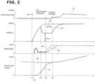
- FIG. 2 is a timing chart for explaining the torque down control of the internal combustion engine 1 in this embodiment, by exemplifying the sailing stop.
- a characteristic line C1 shown by a solid line in FIG. 2 represents an acceleration Ga in the forward and rearward directions of the vehicle.
- a characteristic line C2 shown by a broken line in FIG. 2 represents a target torque Tv of the internal combustion engine 1 when the torque down control is not performed.
- a characteristic line C3 shown by a solid line in FIG. 2 represents a target torque Tt of the internal combustion engine 1 when the torque down control is performed.
- a characteristic line C4 shown by a solid line in FIG. 2 represents a target pressure Pt of the hydraulic fluid supplied to the forward clutch 5.
- a characteristic line C5 shown by a broken line in FIG. 2 represents an actual pressure Pa of the hydraulic fluid supplied to the forward clutch 5.
- a characteristic line C6 shown by a broken line in FIG. 2 represents a rotation speed Rp of the primary pulley 11.
- a characteristic line C7 shown by a solid line in FIG. 2 represents an engine speed Re of the internal combustion engine 1.
- Time t1 is a timing of the accelerator ON.
- the internal combustion engine 1 starts the cranking at this time t1.
- the sailing stop cancel condition is satisfied.
- the internal combustion engine 1 starts the cranking at this time t1. That is, the internal combustion engine 1 is restarted at time t1.
- Time t2 is a timing at which a pre-charge is performed to suppress a delay of the hydraulic response of the forward clutch 5.
- Time t2 is a timing at which a predetermined time period is elapsed from the timing of the accelerator ON. After the pre-charge, the hydraulic pressure of the forward clutch 5 is controlled to be smaller than the hydraulic pressure by which the torque transmission is started, until the engagement command of the forward clutch 5 is outputted.
- Time t3 is a timing at which the engine speed Re of the internal combustion engine 1 is increased to be closer to the rotation speed Rp of the primary pulley 11 so that the rotation speed difference between the internal combustion engine 1 and the primary pulley 11 becomes a second predetermined value B.
- the torque down control is started. That is, the torque down control is performed when the rotation speed difference between the internal combustion engine 1 and the primary pulley 11 becomes equal to or smaller than the second predetermined value B.
- the target torque Tt of the internal combustion engine 1 is limited to the torque lower limit value Tmin.
- Time t4 is a timing at which the rotation speed difference between the internal combustion engine 1 and the primary pulley 11 becomes the first predetermined value A.
- the engagement command of the forward clutch 5 is outputted to increase the target pressure Pt of the hydraulic pressure supplied to the forward clutch 5.
- the actual pressure Pa of the hydraulic pressure supplied to the forward clutch 5 is increased in accordance with the increase of the target pressure Pt of the hydraulic fluid supplied to the forward clutch 5, so that the forward clutch 5 is engaged.
- the first predetermined value A is smaller than the second predetermined value B.
- the driving torque of the internal combustion engine 1 is transmitted to the primary pulley 11 by the engagement of the forward clutch 5 after the engagement command of the forward clutch 5. Then, the acceleration (the forward and rearward G) of the vehicle becomes a positive value when the vehicle is started to be accelerated.
- a timer to measure a timing of the end of the torque down control is started. That is, the timer is started at a timing at which the engagement command of the forward clutch 5 during the torque down control is outputted. That is, the timer is started to count at a timing at which the clutch engagement command is outputted.
- the timer is started at a timing at which the engagement command of the lockup clutch is outputted during the torque down control.
- Time t5 is a timing at which the torque release time period t trq is elapsed from time t4.
- the torque down control is finished at a timing (time t5) at which the torque release time period t trq is elapsed from a timing at which the rotation speed difference between the internal combustion engine 1 and the primary pulley 11 becomes the first predetermined value A during the toque down control. That is, the torque down control is finished at a timing (time t5) at which the torque release time period t trq is elapsed from the engagement command of the forward clutch 5 which is generated during the torque down control.
- the torque down control in case of the coast stop is finished at a timing at which the torque release time period t trq is elapsed from the engagement command of the lockup clutch which is generated during the torque down control.
- the toque release time period t trq is sequentially calculated during the torque down control. At time t5, the internal combustion engine 1 is released from the torque limitation in which the target torque Tt is limited to the torque lower limit value Tmin.
- the acceleration feeling and the deceleration feeling sensed by the driver at the engagement of the forward clutch 5 and the lockup clutch of the lockup mechanism of the torque converter 2 is not generally problematic. This acceleration feeling and the deceleration feeling are dissolved during a relatively short time period. However, these may provide the unnatural feeling to the driver.
- FIG. 3 is a timing chart for explaining the torque down control in a first comparative example, by exemplifying the sailing stop.
- a system configuration of the first comparative example is identical to that of the above-described embodiment of the present invention. Accordingly, the same constitution components have the same symbols. The repetitive explanations are omitted.
- a characteristic line C8 shown by a solid line in FIG. 3 represents an acceleration Gc1 in the forward and rearward directions of the vehicle in the first comparative example.
- a characteristic line C9 shown by a broken line in FIG. 3 represents an acceleration Gc0 when the torque of the internal combustion engine 1 during the torque down control is set to the torque lower limit value Tmin, like the above-described embodiment.
- a characteristic line C10 shown by a broken line in FIG. 3 represents a rotation speed Rp of the primary pulley 11 in the first comparative example.
- a characteristic line C11 shown by a solid line in FIG. 3 represents an engine speed Re of the internal combustion engine 1 in the first comparative example.
- a characteristic line C12 shown by a solid line in FIG. 3 represents a target torque Tt1 of the internal combustion engine 1 in the first comparative example.
- a characteristic line C13 shown by a broken line in FIG. 3 represents a target torque Tt when the torque of the internal combustion engine 1 during the torque down control is set to the torque lower limit value Tmin like the above-described embodiment.
- a characteristic line C14 shown by a solid line in FIG. 3 represents a target pressure Pt of the hydraulic fluid supplied to the forward clutch 5.
- a characteristic line C15 shown by a solid line in FIG. 3 represents a torque Tc1 inputted to the CVT 3 in this first comparative example.
- a characteristic line C16Tc shown by a broken line in FIG. 3 represents a torque Tc inputted to the CVT 3 in the above-described embodiment.
- Time t1 in FIG. 3 is a timing of the accelerator ON.
- Time t2 in FIG. 3 is a timing at which a pre-charge is performed to suppress a delay of the hydraulic response of the forward clutch 5.
- Time t3 in FIG. 3 is a timing at which the torque down control is started.
- Time t4 in FIG. 3 is a timing at which the engagement command of the forward clutch 5 is outputted.
- Time t5 in FIG. 3 is a timing at which the torque down control is finished.
- the target torque Tt1 of the internal combustion engine 1 during the torque down control is excessive. That is, in the first comparative example, the target torque Tt1 of the internal combustion engine during the torque down control is set to be greater than the target torque Tt of the internal combustion engine during the torque down control in the above-described embodiment.
- the driver may feel, as the unnatural feeling, the acceleration feeling sensed at the engagement of the forward clutch 5 when the torque step (torque level difference) becomes large at the engagement of the forward clutch 5.
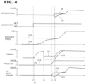
- FIG. 4 is a timing chart for explaining the torque down control in a second comparative example, by exemplifying the sailing stop.
- a system configuration of the second comparative example is identical to that of the above-described embodiment of the present invention. Accordingly, the same constitution components have the same symbols. The repetitive explanations are omitted.
- a characteristic line C17 shown by a solid line in FIG. 4 represents an acceleration Gc2 in the forward and rearward directions of the vehicle in the second comparative example.
- a characteristic line C9 shown by a broken line in FIG. 4 represents an acceleration Gc0 when the torque of the internal combustion engine 1 during the torque down control is set to the torque lower limit value Tmin, like the above-described embodiment.
- a characteristic line C18 shown by a broken line in FIG. 4 represents a rotation speed Rp of the primary pulley 11 in the second comparative example.
- a characteristic line C19 shown by a solid line in FIG. 4 represents an engine speed Re of the internal combustion engine 1 in the second comparative example.
- a characteristic line C20 shown by a solid line in FIG. 4 represents a target torque Tt2 of the internal combustion engine 1 in the second comparative example.
- a characteristic line C13 shown by a broken line in FIG. 4 represents a target torque Tt when the torque of the internal combustion engine 1 during the torque down control is set to the torque lower limit value Tmin like the above-described embodiment.
- a characteristic line C14 shown by a solid line in FIG. 4 represents a target pressure Pt of the hydraulic fluid supplied to the forward clutch 5.
- a characteristic line C21 shown by a solid line in FIG. 4 represents a torque Tc2 inputted to the CVT 3 in this second comparative example.
- a characteristic line C16 shown by a broken line in FIG. 4 represents a torque Tc inputted to the CVT 3 in the above-described embodiment.
- Time t3. in FIG. 4 is a timing of the accelerator ON.
- Time t2 in FIG. 4 is a timing at which a pre-charge is performed to suppress a delay of the hydraulic response of the forward clutch 5.
- Time t3 in FIG. 4 is a timing at which the torque down control is started.
- Time t4 in FIG. 4 is a timing at which the engagement command of the forward clutch 5 is outputted.
- Time t5 in FIG. 4 is a timing at which the torque down control is finished.
- the target torque Tt2 of the internal combustion engine 1 during the torque down control is deficient. That is, in the second comparative example, the target torque Tt2 of the internal combustion engine during the torque down control is set to be smaller than the target torque Tt of the internal combustion engine during the torque down control in the above-described embodiment.
- the driver may feel, as the unnatural feeling, the deceleration feeling sensed at the engagement of the forward clutch 5 when the torque step (torque level difference) becomes large at the engagement of the forward clutch 5.
- the torque release time period t trq is set to be relatively short so as to prioritize the followability, and to dissolve the unnatural feeling of the driver by below-described reasons.
- the torque release time period t trq is set so as not to be extremely short to suppress the acceleration feeling of the driver, and thereby to decrease the unnatural feeling of the driver.
- the torque release time period t trq is set to be shorter to prioritize the followability.
- the torque release time period t trq is set so as not to be extremely short to suppress the acceleration feeling of the driver, and thereby to decrease the unnatural feeling of the driver.
- the torque down control is finished at a timing at which the predetermined torque release time period t trq is elapsed from the timing at which the rotation speed difference between the engine speed Re of the internal combustion engine 1 and the input side rotation speed of the CVT 3 (the rotation speed Rp of the primary pulley 11) becomes the first predetermined value A.
- the torque down control is finished at a timing at which the predetermined torque release time period t trq is elapsed from the engagement command of the lockup clutch of the lockup mechanism of the torque converter 2, or the forward clutch 5. With this, it is possible to control the end timing of the torque down control.
- the torque release time period t trq is set in accordance with the vehicle speed and the accelerator opening degree. With this, it is possible to set the torque release time period t trq so as to compensate for the traveling resistance (the air resistance and the rolling resistance), and the resistance of the power train of the vehicle.
- the torque release time period t trq is set to be relatively short so as to recover (retrieve) the delay by the rotation increase. With this, it is possible to suppress the deterioration of the response characteristic (the acceleration characteristic) of the vehicle at the restart of the internal combustion engine 1 which is automatically stopped.
- the traveling resistance of the vehicle is relatively small.
- the transmission gear ratio of the CVT 3 is the low side. Accordingly, the torque release time period t trq is set to be relatively long. With this, it is possible to decrease the unnecessary acceleration feeling generated at the engagement of the lockup clutch and the forward clutch 5.
- the torque release time period t trq is set to be relatively short. With this, it is possible to improve the response characteristic (the acceleration characteristic) of the vehicle at the restart of the internal combustion engine 1 which is automatically stopped.
- the torque release time period t trq is set to be relatively long. With this, it is possible to decrease the unnecessary acceleration feeling at the engagement of the lockup clutch and the forward clutch 5.
- the accelerator opening degree is small, it is possible to set the torque release time period t trq to be the relatively long value, and to finish the torque down control after waiting for the full engagement of the lockup clutch and the forward clutch 5. In this case, it is possible to further decrease the engagement shock generated at the engagement of the lockup clutch and the forward clutch 5.
- FIG. 5 and FIG. 6 are flowcharts showing a flow of the control of the internal combustion engine according to the present invention.
- FIG. 5 is a flowchart showing one example of the flow of the control at the restart of the internal combustion engine.
- FIG. 6 is a flowchart showing one example of the flow of the control when the torque lower limit value Tmin and the torque release time period t trq are calculated.
- FIG. 5 is explained.
- step S1 it is judged whether or not the internal combustion engine 1 is automatically stopped during the traveling.
- the process proceeds to step S2.
- this routine is finished.
- step S2 it is judged whether or not the automatic restart condition is satisfied.
- the process proceeds to step S3.
- this routine is finished.
- step S3 the internal combustion engine 1 is started.
- step S4 it is judged whether or not the rotation speed difference between the engine speed Re of the internal combustion engine 1 and the rotation speed Rp of the primary pulley 11 of the CVT 3 becomes the second predetermined value B.
- step S5 the process proceeds to step S5.
- step S5 the torque down control is started.
- the torque lower limit value Tmin which is the target torque in the torque down control is read.
- This torque lower limit value Tmin is calculated by using the vehicle speed and the accelerator opening degree.
- the torque lower limit value Tmin is varied in accordance with the driving state during the torque down control. That is, the torque lower limit value Tmin is varied in accordance with the vehicle speed and the accelerator opening degree during the torque down control.
- step S7 it is judged whether or not the rotation speed difference between the engine speed Re of the internal combustion engine 1 and the rotation speed Rp of the primary pulley 11 of the CVT 3 becomes the first predetermined value A.
- the first predetermined value A is set to be smaller than the second predetermined value B.
- step S8 the clutch engagement is started. That is, the engagement of the forward clutch 5 is started at the recovery from the sailing stop. The engagement of the lockup clutch is started at the recovery from the coast stop.
- this timer is started from the timing at which the rotation speed difference between the engine speed Re and the rotation speed Rp of the primary pulley 11 becomes the first predetermined value A.
- the torque release time period t trq is read.
- This torque release time period t trq is calculated by using the vehicle speed and the accelerator opening degree.
- the torque release time period t trq is varied in accordance with the driving state during the torque down control. That is, the torque release time period t trq is varied in accordance with the vehicle speed and the accelerator opening degree during the torque down control.
- step 511 it is judged whether or not the torque release time period t trq is elapsed from the start of the timer.
- the process proceeds to step S12.
- the process proceeds to step S10.
- step S12 the torque down control is finished.
- FIG. 6 is explained.
- step S21 it is judged whether or not the torque down control is started.
- the process proceeds to step S22.
- this routine is finished.
- step s22 the vehicle speed and the accelerator opening degree are read.
- the torque lower limit value Tmin is calculated by using the vehicle speed and the accelerator opening degree.
- the torque release time period t trq is calculated by using the vehicle speed and the accelerator opening degree.
- the current torque lower limit value Tmin calculated at step S23 is read at step S6 of FIG. 5 .
- the current torque release time period t trq calculated at step S24 is read at step S10 of FIG. 5 .
- the above-described embodiment relates to the control method and the control device for the internal combustion engine.
- the present invention is applicable to the restart of the internal combustion engine 1 which is in the sailing stop state, and the restart of the internal combustion engine 1 which is in the coast stop state.
Claims (3)
- Ein Steuerungsverfahren für einen Verbrennungsmotor (1), der eine Antriebsquelle (7) eines Fahrzeugs ist, bei dem eine Antriebskraft auf ein Getriebe (3) übertragen wird, wenn eine Kupplung (5) eingerückt ist, wobei das Steuerungsverfahren umfasst:wenn der Verbrennungsmotor (1), der in einem Zustand, in dem die Kupplung (5) entkuppelt ist, automatisch angehalten wird, wieder gestartet wird,Durchführen einer Drehmomentabwärtssteuerung, um ein Solldrehmoment des Verbrennungsmotors (1) zu verringern, wenn die Kupplung (5) eingekuppelt ist;Einstellen einer vorbestimmten Drehmomentfreigabezeitdauer, die kürzer ist, wenn eine Fahrzeuggeschwindigkeit höher ist und/oder kürzer ist, wenn ein Gaspedalöffnungsgrad größer ist; undBeenden der Drehmomentabwärtssteuerung zu einem Zeitpunkt, zu dem die Drehmomentfreigabezeitdauer von einem Einkuppelbefehl der Kupplung (5), der während der Drehmomentabwärtssteuerung erzeugt wird, verstrichen ist.
- Das Steuerungsverfahren für einen Verbrennungsmotor (1) gemäß Anspruch 1, wobei
die Drehmomentabwärtssteuerung gestartet wird, wenn eine Drehzahldifferenz zwischen einer Motordrehzahl des Verbrennungsmotors (1) und einer eingangsseitigen Drehzahl des Getriebes (3), das über die Kupplung (5) mit dem Verbrennungsmotor (1) verbunden ist, einen vorgegebenen Wert erreicht. - Eine Steuervorrichtung für einen Verbrennungsmotor (1), wobei die Steuervorrichtung umfasst:einen Verbrennungsmotor (1), der so angeordnet ist, dass er eine Antriebskraft eines Antriebsrades eines Fahrzeugs überträgt;ein Getriebe (3), das zwischen dem Verbrennungsmotor (1) und dem Antriebsrad angeordnet ist;eine Kupplung (5), die zwischen dem Verbrennungsmotor (1) und dem Getriebe (3) angeordnet ist;einen Abschnitt zur Drehmomentabwärtssteuerung, der konfiguriert ist, eine Drehmomentabwärtssteuerung durchzuführen, um ein Solldrehmoment des Verbrennungsmotors (1) zu verringern, wenn die Kupplung (5) eingekuppelt ist; undeinen Abschnitt zur Berechnung der Drehmomentfreigabezeitdauer, konfiguriert ist, eine vorbestimmte Drehmomentfreigabezeitdauer so einzustellen, dass sie kürzer ist, wenn eine Fahrzeuggeschwindigkeit höher ist, und/oder dass sie kürzer ist, wenn ein Gaspedalöffnungsgrad größer ist, wobeider Abschnitt zur Drehmomentabwärtssteuerung konfiguriert ist, die Abschnitt zur Drehmomentabwärtssteuerung zu einem Zeitpunkt zu beenden, zu dem die Zeitperiode zum Lösen des Drehmoments von einem Einkuppelbefehl der Kupplung (5), der während der Drehmomentabwärtssteuerung erzeugt wird, verstrichen ist.
Applications Claiming Priority (1)
| Application Number | Priority Date | Filing Date | Title |
|---|---|---|---|
| PCT/JP2017/041971 WO2019102541A1 (ja) | 2017-11-22 | 2017-11-22 | 内燃機関の制御方法及び内燃機関の制御装置 |
Publications (3)
| Publication Number | Publication Date |
|---|---|
| EP3715610A1 EP3715610A1 (de) | 2020-09-30 |
| EP3715610A4 EP3715610A4 (de) | 2020-12-16 |
| EP3715610B1 true EP3715610B1 (de) | 2024-03-27 |
Family
ID=66631836
Family Applications (1)
| Application Number | Title | Priority Date | Filing Date |
|---|---|---|---|
| EP17932879.4A Active EP3715610B1 (de) | 2017-11-22 | 2017-11-22 | Verbrennungsmotorsteuerungsverfahren und verbrennungsmotorsteuerungsvorrichtung |
Country Status (5)
| Country | Link |
|---|---|
| US (1) | US11378024B2 (de) |
| EP (1) | EP3715610B1 (de) |
| JP (1) | JP6868710B2 (de) |
| CN (1) | CN111433446B (de) |
| WO (1) | WO2019102541A1 (de) |
Family Cites Families (20)
| Publication number | Priority date | Publication date | Assignee | Title |
|---|---|---|---|---|
| JP2927153B2 (ja) * | 1993-09-10 | 1999-07-28 | トヨタ自動車株式会社 | 車両用ロックアップクラッチの制御装置 |
| JP4622148B2 (ja) | 2001-04-26 | 2011-02-02 | トヨタ自動車株式会社 | 内燃機関の始動制御装置 |
| DE10229035B4 (de) | 2002-06-28 | 2015-10-15 | Robert Bosch Gmbh | Verfahren zur Steuerung der Antriebseinheit eines Fahrzeugs |
| JP4478006B2 (ja) * | 2004-12-10 | 2010-06-09 | ヤマハ発動機株式会社 | エンジンの制御装置、エンジンの制御方法及び鞍乗型車両 |
| JP4129264B2 (ja) * | 2005-02-14 | 2008-08-06 | ジヤトコ株式会社 | 自動変速機の制御装置 |
| JP2007112258A (ja) * | 2005-10-19 | 2007-05-10 | Nissan Motor Co Ltd | ハイブリッド駆動装置のエンジン始動制御装置 |
| KR100828674B1 (ko) * | 2006-08-02 | 2008-05-09 | 현대자동차주식회사 | 자동변속기 차량의 엔진 토크 제한장치 및 방법 |
| JP4849542B2 (ja) * | 2006-10-27 | 2012-01-11 | ヤマハ発動機株式会社 | 変速制御装置および鞍乗型車両 |
| KR100833614B1 (ko) * | 2007-06-28 | 2008-05-30 | 주식회사 케피코 | 아이들스탑 기능을 가진 차량의 엔진 제어 방법 |
| JP4683023B2 (ja) * | 2007-08-21 | 2011-05-11 | 日産自動車株式会社 | 車両の加速ショック軽減装置 |
| EP2287488B1 (de) * | 2008-06-04 | 2014-01-22 | Nissan Motor Co., Ltd. | Befestigungsdruck-steuervorrichtung zum starten eines reibungselements zum zeitpunkt des steuerungsleerlaufs eines fahrzeugs |
| JP5170569B2 (ja) * | 2009-03-31 | 2013-03-27 | アイシン・エィ・ダブリュ株式会社 | ハイブリッド駆動装置 |
| JP5756002B2 (ja) * | 2011-12-09 | 2015-07-29 | ジヤトコ株式会社 | 車両制御装置および車両の制御方法 |
| JP5513570B2 (ja) * | 2012-09-04 | 2014-06-04 | 本田技研工業株式会社 | 車両制御装置 |
| US8894540B2 (en) * | 2012-09-13 | 2014-11-25 | Ford Global Technologies, Llc | Method and apparatus for controlling engine shutdown in hybrid vehicles |
| JP5849929B2 (ja) | 2012-10-25 | 2016-02-03 | アイシン精機株式会社 | 車両用駆動装置 |
| US9656666B2 (en) * | 2014-08-28 | 2017-05-23 | Ford Global Technologies, Llc | Methods and systems for starting an engine |
| JP6260564B2 (ja) * | 2015-03-25 | 2018-01-17 | トヨタ自動車株式会社 | ハイブリッド車両の駆動装置 |
| US11041451B2 (en) * | 2017-11-22 | 2021-06-22 | Nissan Motor Co., Ltd. | Internal combustion engine control method and internal combustion engine control device |
| CN111566390B (zh) * | 2017-12-28 | 2021-11-09 | 加特可株式会社 | 无级变速器的控制装置以及控制方法 |
-
2017
- 2017-11-22 WO PCT/JP2017/041971 patent/WO2019102541A1/ja unknown
- 2017-11-22 US US16/765,541 patent/US11378024B2/en active Active
- 2017-11-22 EP EP17932879.4A patent/EP3715610B1/de active Active
- 2017-11-22 CN CN201780096886.6A patent/CN111433446B/zh active Active
- 2017-11-22 JP JP2019556014A patent/JP6868710B2/ja active Active
Also Published As
| Publication number | Publication date |
|---|---|
| JP6868710B2 (ja) | 2021-05-12 |
| JPWO2019102541A1 (ja) | 2020-11-19 |
| EP3715610A1 (de) | 2020-09-30 |
| US11378024B2 (en) | 2022-07-05 |
| WO2019102541A1 (ja) | 2019-05-31 |
| CN111433446A (zh) | 2020-07-17 |
| US20200309044A1 (en) | 2020-10-01 |
| CN111433446B (zh) | 2022-06-24 |
| EP3715610A4 (de) | 2020-12-16 |
Similar Documents
| Publication | Publication Date | Title |
|---|---|---|
| EP3715609B1 (de) | Verbrennungsmotorsteuerungsverfahren und verbrennungsmotorsteuerungsvorrichtung | |
| US7150333B2 (en) | Vehicle control apparatus and method | |
| JP5907279B2 (ja) | 車両の制御装置 | |
| WO2015041044A1 (ja) | 車両の制御装置 | |
| EP3183451A1 (de) | Steuergerät für fahrzeug und steuerungsverfahren für fahrzeug | |
| US20190118820A1 (en) | Vehicle control apparatus | |
| JP4606077B2 (ja) | 内燃機関の始動=停止=作動の制御のための方法及び制御装置 | |
| JP6150081B2 (ja) | 車両制御装置 | |
| CN111183078B (zh) | 内燃机的控制方法及内燃机的控制装置 | |
| EP3715610B1 (de) | Verbrennungsmotorsteuerungsverfahren und verbrennungsmotorsteuerungsvorrichtung | |
| EP3335956A2 (de) | Steuergerät für fahrzeug | |
| JP6582685B2 (ja) | 車両走行制御方法及び車両走行制御装置 | |
| JP2003278805A (ja) | クラッチ制御装置 | |
| JP4180559B2 (ja) | 車両のエンジン自動停止装置 | |
| JP2001082594A (ja) | 車両用制御装置 | |
| JP2018035760A (ja) | 車両の制御装置 | |
| JP6319180B2 (ja) | 車両制御装置 | |
| WO2019069444A1 (ja) | 内燃機関の制御方法及び内燃機関の制御装置 | |
| JPH10329582A (ja) | 自動クラッチ制御装置 |
Legal Events
| Date | Code | Title | Description |
|---|---|---|---|
| STAA | Information on the status of an ep patent application or granted ep patent |
Free format text: STATUS: THE INTERNATIONAL PUBLICATION HAS BEEN MADE |
|
| PUAI | Public reference made under article 153(3) epc to a published international application that has entered the european phase |
Free format text: ORIGINAL CODE: 0009012 |
|
| STAA | Information on the status of an ep patent application or granted ep patent |
Free format text: STATUS: REQUEST FOR EXAMINATION WAS MADE |
|
| 17P | Request for examination filed |
Effective date: 20200609 |
|
| AK | Designated contracting states |
Kind code of ref document: A1 Designated state(s): AL AT BE BG CH CY CZ DE DK EE ES FI FR GB GR HR HU IE IS IT LI LT LU LV MC MK MT NL NO PL PT RO RS SE SI SK SM TR |
|
| AX | Request for extension of the european patent |
Extension state: BA ME |
|
| A4 | Supplementary search report drawn up and despatched |
Effective date: 20201112 |
|
| RIC1 | Information provided on ipc code assigned before grant |
Ipc: F02D 29/02 20060101AFI20201106BHEP Ipc: F02D 41/02 20060101ALI20201106BHEP Ipc: F02D 41/06 20060101ALI20201106BHEP Ipc: F02D 29/00 20060101ALI20201106BHEP |
|
| DAV | Request for validation of the european patent (deleted) | ||
| DAX | Request for extension of the european patent (deleted) | ||
| RAP3 | Party data changed (applicant data changed or rights of an application transferred) |
Owner name: RENAULT S.A.S Owner name: NISSAN MOTOR CO., LTD. |
|
| RAP3 | Party data changed (applicant data changed or rights of an application transferred) |
Owner name: RENAULT S.A.S Owner name: NISSAN MOTOR CO., LTD. |
|
| GRAP | Despatch of communication of intention to grant a patent |
Free format text: ORIGINAL CODE: EPIDOSNIGR1 |
|
| STAA | Information on the status of an ep patent application or granted ep patent |
Free format text: STATUS: GRANT OF PATENT IS INTENDED |
|
| INTG | Intention to grant announced |
Effective date: 20231115 |
|
| RAP1 | Party data changed (applicant data changed or rights of an application transferred) |
Owner name: NEW H POWERTRAIN HOLDING, S.L.U. Owner name: NISSAN MOTOR CO., LTD. |
|
| GRAS | Grant fee paid |
Free format text: ORIGINAL CODE: EPIDOSNIGR3 |
|
| GRAA | (expected) grant |
Free format text: ORIGINAL CODE: 0009210 |
|
| STAA | Information on the status of an ep patent application or granted ep patent |
Free format text: STATUS: THE PATENT HAS BEEN GRANTED |
|
| AK | Designated contracting states |
Kind code of ref document: B1 Designated state(s): AL AT BE BG CH CY CZ DE DK EE ES FI FR GB GR HR HU IE IS IT LI LT LU LV MC MK MT NL NO PL PT RO RS SE SI SK SM TR |
|
| REG | Reference to a national code |
Ref country code: GB Ref legal event code: FG4D |
|
| REG | Reference to a national code |
Ref country code: CH Ref legal event code: EP |
|
| REG | Reference to a national code |
Ref country code: DE Ref legal event code: R096 Ref document number: 602017080506 Country of ref document: DE |