EP3715519B1 - Spinnvliesstoff, verfahren zur herstellung eines spinnvliesstoffes und prägewalze - Google Patents
Spinnvliesstoff, verfahren zur herstellung eines spinnvliesstoffes und prägewalze Download PDFInfo
- Publication number
- EP3715519B1 EP3715519B1 EP19802023.2A EP19802023A EP3715519B1 EP 3715519 B1 EP3715519 B1 EP 3715519B1 EP 19802023 A EP19802023 A EP 19802023A EP 3715519 B1 EP3715519 B1 EP 3715519B1
- Authority
- EP
- European Patent Office
- Prior art keywords
- woven fabric
- spunbonded non
- projection
- embossing roll
- woven
- Prior art date
- Legal status (The legal status is an assumption and is not a legal conclusion. Google has not performed a legal analysis and makes no representation as to the accuracy of the status listed.)
- Active
Links
- 239000004745 nonwoven fabric Substances 0.000 title claims description 162
- 238000004519 manufacturing process Methods 0.000 title claims description 39
- 238000000034 method Methods 0.000 title claims description 37
- 239000000835 fiber Substances 0.000 claims description 109
- 238000004049 embossing Methods 0.000 claims description 78
- 229920001169 thermoplastic Polymers 0.000 claims description 34
- 239000000463 material Substances 0.000 claims description 31
- 238000005452 bending Methods 0.000 claims description 27
- 229920000642 polymer Polymers 0.000 claims description 26
- 235000019589 hardness Nutrition 0.000 claims description 22
- QQONPFPTGQHPMA-UHFFFAOYSA-N propylene Natural products CC=C QQONPFPTGQHPMA-UHFFFAOYSA-N 0.000 claims description 19
- 125000004805 propylene group Chemical group [H]C([H])([H])C([H])([*:1])C([H])([H])[*:2] 0.000 claims description 18
- 230000006835 compression Effects 0.000 claims description 17
- 238000007906 compression Methods 0.000 claims description 17
- 238000012669 compression test Methods 0.000 claims description 16
- 238000000151 deposition Methods 0.000 claims description 8
- 239000004744 fabric Substances 0.000 claims description 6
- 238000002074 melt spinning Methods 0.000 claims description 6
- 239000010410 layer Substances 0.000 description 32
- 238000012360 testing method Methods 0.000 description 29
- 238000009987 spinning Methods 0.000 description 21
- 238000002844 melting Methods 0.000 description 16
- 230000008018 melting Effects 0.000 description 16
- 230000000052 comparative effect Effects 0.000 description 15
- 229920005604 random copolymer Polymers 0.000 description 14
- -1 ethylene, propylene, 1-butene Chemical class 0.000 description 12
- 230000002349 favourable effect Effects 0.000 description 12
- 238000001816 cooling Methods 0.000 description 11
- 239000004711 α-olefin Substances 0.000 description 11
- WSSSPWUEQFSQQG-UHFFFAOYSA-N 4-methyl-1-pentene Chemical compound CC(C)CC=C WSSSPWUEQFSQQG-UHFFFAOYSA-N 0.000 description 10
- 239000002131 composite material Substances 0.000 description 9
- VXNZUUAINFGPBY-UHFFFAOYSA-N 1-Butene Chemical compound CCC=C VXNZUUAINFGPBY-UHFFFAOYSA-N 0.000 description 8
- 229920001384 propylene homopolymer Polymers 0.000 description 8
- 239000000523 sample Substances 0.000 description 8
- 238000011156 evaluation Methods 0.000 description 6
- 238000012545 processing Methods 0.000 description 6
- 229920005989 resin Polymers 0.000 description 6
- 239000011347 resin Substances 0.000 description 6
- 230000000712 assembly Effects 0.000 description 5
- 238000000429 assembly Methods 0.000 description 5
- LIKMAJRDDDTEIG-UHFFFAOYSA-N 1-hexene Chemical compound CCCCC=C LIKMAJRDDDTEIG-UHFFFAOYSA-N 0.000 description 4
- KWKAKUADMBZCLK-UHFFFAOYSA-N 1-octene Chemical compound CCCCCCC=C KWKAKUADMBZCLK-UHFFFAOYSA-N 0.000 description 4
- 229920001577 copolymer Polymers 0.000 description 4
- 229920001519 homopolymer Polymers 0.000 description 4
- 238000005259 measurement Methods 0.000 description 4
- 239000012567 medical material Substances 0.000 description 4
- 229910000831 Steel Inorganic materials 0.000 description 3
- 239000010959 steel Substances 0.000 description 3
- VGGSQFUCUMXWEO-UHFFFAOYSA-N Ethene Chemical compound C=C VGGSQFUCUMXWEO-UHFFFAOYSA-N 0.000 description 2
- 239000005977 Ethylene Substances 0.000 description 2
- 230000002745 absorbent Effects 0.000 description 2
- 239000002250 absorbent Substances 0.000 description 2
- 239000000654 additive Substances 0.000 description 2
- 230000000996 additive effect Effects 0.000 description 2
- 239000003795 chemical substances by application Substances 0.000 description 2
- 238000005520 cutting process Methods 0.000 description 2
- 229920000092 linear low density polyethylene Polymers 0.000 description 2
- 239000004707 linear low-density polyethylene Substances 0.000 description 2
- 239000000203 mixture Substances 0.000 description 2
- TVMXDCGIABBOFY-UHFFFAOYSA-N n-Octanol Natural products CCCCCCCC TVMXDCGIABBOFY-UHFFFAOYSA-N 0.000 description 2
- 239000005022 packaging material Substances 0.000 description 2
- YWAKXRMUMFPDSH-UHFFFAOYSA-N pentene Chemical compound CCCC=C YWAKXRMUMFPDSH-UHFFFAOYSA-N 0.000 description 2
- 230000035699 permeability Effects 0.000 description 2
- 238000006116 polymerization reaction Methods 0.000 description 2
- 235000019587 texture Nutrition 0.000 description 2
- 229910052723 transition metal Inorganic materials 0.000 description 2
- 150000003624 transition metals Chemical class 0.000 description 2
- QNRATNLHPGXHMA-XZHTYLCXSA-N (r)-(6-ethoxyquinolin-4-yl)-[(2s,4s,5r)-5-ethyl-1-azabicyclo[2.2.2]octan-2-yl]methanol;hydrochloride Chemical compound Cl.C([C@H]([C@H](C1)CC)C2)CN1[C@@H]2[C@H](O)C1=CC=NC2=CC=C(OCC)C=C21 QNRATNLHPGXHMA-XZHTYLCXSA-N 0.000 description 1
- 239000004743 Polypropylene Substances 0.000 description 1
- RTAQQCXQSZGOHL-UHFFFAOYSA-N Titanium Chemical compound [Ti] RTAQQCXQSZGOHL-UHFFFAOYSA-N 0.000 description 1
- 239000011954 Ziegler–Natta catalyst Substances 0.000 description 1
- 150000001336 alkenes Chemical class 0.000 description 1
- 239000003963 antioxidant agent Substances 0.000 description 1
- 230000003078 antioxidant effect Effects 0.000 description 1
- 239000002216 antistatic agent Substances 0.000 description 1
- 239000002981 blocking agent Substances 0.000 description 1
- 238000012662 bulk polymerization Methods 0.000 description 1
- 125000004432 carbon atom Chemical group C* 0.000 description 1
- 150000001875 compounds Chemical class 0.000 description 1
- 125000000058 cyclopentadienyl group Chemical group C1(=CC=CC1)* 0.000 description 1
- 230000003247 decreasing effect Effects 0.000 description 1
- 230000007547 defect Effects 0.000 description 1
- 230000008021 deposition Effects 0.000 description 1
- 230000000694 effects Effects 0.000 description 1
- 238000009760 electrical discharge machining Methods 0.000 description 1
- 238000005323 electroforming Methods 0.000 description 1
- 238000005530 etching Methods 0.000 description 1
- 229920001903 high density polyethylene Polymers 0.000 description 1
- 239000004700 high-density polyethylene Substances 0.000 description 1
- 239000004611 light stabiliser Substances 0.000 description 1
- 229920001684 low density polyethylene Polymers 0.000 description 1
- 239000004702 low-density polyethylene Substances 0.000 description 1
- 239000000314 lubricant Substances 0.000 description 1
- 239000000155 melt Substances 0.000 description 1
- 229910052751 metal Inorganic materials 0.000 description 1
- 239000002184 metal Substances 0.000 description 1
- 239000012968 metallocene catalyst Substances 0.000 description 1
- 239000002667 nucleating agent Substances 0.000 description 1
- JRZJOMJEPLMPRA-UHFFFAOYSA-N olefin Natural products CCCCCCCC=C JRZJOMJEPLMPRA-UHFFFAOYSA-N 0.000 description 1
- 230000000737 periodic effect Effects 0.000 description 1
- 230000000704 physical effect Effects 0.000 description 1
- 239000000049 pigment Substances 0.000 description 1
- 239000004033 plastic Substances 0.000 description 1
- 229920003023 plastic Polymers 0.000 description 1
- 239000000088 plastic resin Substances 0.000 description 1
- 229920002647 polyamide Polymers 0.000 description 1
- 229920000728 polyester Polymers 0.000 description 1
- 229920001155 polypropylene Polymers 0.000 description 1
- 229920005606 polypropylene copolymer Polymers 0.000 description 1
- 239000002356 single layer Substances 0.000 description 1
- 239000002002 slurry Substances 0.000 description 1
- 239000007787 solid Substances 0.000 description 1
- 239000003381 stabilizer Substances 0.000 description 1
- 230000001629 suppression Effects 0.000 description 1
- 229920005992 thermoplastic resin Polymers 0.000 description 1
- 229910052719 titanium Inorganic materials 0.000 description 1
- 239000010936 titanium Substances 0.000 description 1
- 239000012808 vapor phase Substances 0.000 description 1
- 239000002759 woven fabric Substances 0.000 description 1
Images


Classifications
-
- D—TEXTILES; PAPER
- D04—BRAIDING; LACE-MAKING; KNITTING; TRIMMINGS; NON-WOVEN FABRICS
- D04H—MAKING TEXTILE FABRICS, e.g. FROM FIBRES OR FILAMENTARY MATERIAL; FABRICS MADE BY SUCH PROCESSES OR APPARATUS, e.g. FELTS, NON-WOVEN FABRICS; COTTON-WOOL; WADDING ; NON-WOVEN FABRICS FROM STAPLE FIBRES, FILAMENTS OR YARNS, BONDED WITH AT LEAST ONE WEB-LIKE MATERIAL DURING THEIR CONSOLIDATION
- D04H3/00—Non-woven fabrics formed wholly or mainly of yarns or like filamentary material of substantial length
- D04H3/08—Non-woven fabrics formed wholly or mainly of yarns or like filamentary material of substantial length characterised by the method of strengthening or consolidating
- D04H3/14—Non-woven fabrics formed wholly or mainly of yarns or like filamentary material of substantial length characterised by the method of strengthening or consolidating with bonds between thermoplastic yarns or filaments produced by welding
- D04H3/147—Composite yarns or filaments
-
- D—TEXTILES; PAPER
- D04—BRAIDING; LACE-MAKING; KNITTING; TRIMMINGS; NON-WOVEN FABRICS
- D04H—MAKING TEXTILE FABRICS, e.g. FROM FIBRES OR FILAMENTARY MATERIAL; FABRICS MADE BY SUCH PROCESSES OR APPARATUS, e.g. FELTS, NON-WOVEN FABRICS; COTTON-WOOL; WADDING ; NON-WOVEN FABRICS FROM STAPLE FIBRES, FILAMENTS OR YARNS, BONDED WITH AT LEAST ONE WEB-LIKE MATERIAL DURING THEIR CONSOLIDATION
- D04H3/00—Non-woven fabrics formed wholly or mainly of yarns or like filamentary material of substantial length
- D04H3/08—Non-woven fabrics formed wholly or mainly of yarns or like filamentary material of substantial length characterised by the method of strengthening or consolidating
- D04H3/16—Non-woven fabrics formed wholly or mainly of yarns or like filamentary material of substantial length characterised by the method of strengthening or consolidating with bonds between thermoplastic filaments produced in association with filament formation, e.g. immediately following extrusion
-
- B—PERFORMING OPERATIONS; TRANSPORTING
- B31—MAKING ARTICLES OF PAPER, CARDBOARD OR MATERIAL WORKED IN A MANNER ANALOGOUS TO PAPER; WORKING PAPER, CARDBOARD OR MATERIAL WORKED IN A MANNER ANALOGOUS TO PAPER
- B31F—MECHANICAL WORKING OR DEFORMATION OF PAPER, CARDBOARD OR MATERIAL WORKED IN A MANNER ANALOGOUS TO PAPER
- B31F1/00—Mechanical deformation without removing material, e.g. in combination with laminating
- B31F1/07—Embossing, i.e. producing impressions formed by locally deep-drawing, e.g. using rolls provided with complementary profiles
-
- B—PERFORMING OPERATIONS; TRANSPORTING
- B32—LAYERED PRODUCTS
- B32B—LAYERED PRODUCTS, i.e. PRODUCTS BUILT-UP OF STRATA OF FLAT OR NON-FLAT, e.g. CELLULAR OR HONEYCOMB, FORM
- B32B3/00—Layered products comprising a layer with external or internal discontinuities or unevennesses, or a layer of non-planar form; Layered products having particular features of form
- B32B3/26—Layered products comprising a layer with external or internal discontinuities or unevennesses, or a layer of non-planar form; Layered products having particular features of form characterised by a particular shape of the outline of the cross-section of a continuous layer; characterised by a layer with cavities or internal voids ; characterised by an apertured layer
- B32B3/30—Layered products comprising a layer with external or internal discontinuities or unevennesses, or a layer of non-planar form; Layered products having particular features of form characterised by a particular shape of the outline of the cross-section of a continuous layer; characterised by a layer with cavities or internal voids ; characterised by an apertured layer characterised by a layer formed with recesses or projections, e.g. hollows, grooves, protuberances, ribs
-
- B—PERFORMING OPERATIONS; TRANSPORTING
- B32—LAYERED PRODUCTS
- B32B—LAYERED PRODUCTS, i.e. PRODUCTS BUILT-UP OF STRATA OF FLAT OR NON-FLAT, e.g. CELLULAR OR HONEYCOMB, FORM
- B32B5/00—Layered products characterised by the non- homogeneity or physical structure, i.e. comprising a fibrous, filamentary, particulate or foam layer; Layered products characterised by having a layer differing constitutionally or physically in different parts
- B32B5/02—Layered products characterised by the non- homogeneity or physical structure, i.e. comprising a fibrous, filamentary, particulate or foam layer; Layered products characterised by having a layer differing constitutionally or physically in different parts characterised by structural features of a fibrous or filamentary layer
- B32B5/022—Non-woven fabric
-
- B—PERFORMING OPERATIONS; TRANSPORTING
- B32—LAYERED PRODUCTS
- B32B—LAYERED PRODUCTS, i.e. PRODUCTS BUILT-UP OF STRATA OF FLAT OR NON-FLAT, e.g. CELLULAR OR HONEYCOMB, FORM
- B32B5/00—Layered products characterised by the non- homogeneity or physical structure, i.e. comprising a fibrous, filamentary, particulate or foam layer; Layered products characterised by having a layer differing constitutionally or physically in different parts
- B32B5/02—Layered products characterised by the non- homogeneity or physical structure, i.e. comprising a fibrous, filamentary, particulate or foam layer; Layered products characterised by having a layer differing constitutionally or physically in different parts characterised by structural features of a fibrous or filamentary layer
- B32B5/024—Woven fabric
-
- B—PERFORMING OPERATIONS; TRANSPORTING
- B32—LAYERED PRODUCTS
- B32B—LAYERED PRODUCTS, i.e. PRODUCTS BUILT-UP OF STRATA OF FLAT OR NON-FLAT, e.g. CELLULAR OR HONEYCOMB, FORM
- B32B5/00—Layered products characterised by the non- homogeneity or physical structure, i.e. comprising a fibrous, filamentary, particulate or foam layer; Layered products characterised by having a layer differing constitutionally or physically in different parts
- B32B5/02—Layered products characterised by the non- homogeneity or physical structure, i.e. comprising a fibrous, filamentary, particulate or foam layer; Layered products characterised by having a layer differing constitutionally or physically in different parts characterised by structural features of a fibrous or filamentary layer
- B32B5/026—Knitted fabric
-
- B—PERFORMING OPERATIONS; TRANSPORTING
- B32—LAYERED PRODUCTS
- B32B—LAYERED PRODUCTS, i.e. PRODUCTS BUILT-UP OF STRATA OF FLAT OR NON-FLAT, e.g. CELLULAR OR HONEYCOMB, FORM
- B32B5/00—Layered products characterised by the non- homogeneity or physical structure, i.e. comprising a fibrous, filamentary, particulate or foam layer; Layered products characterised by having a layer differing constitutionally or physically in different parts
- B32B5/02—Layered products characterised by the non- homogeneity or physical structure, i.e. comprising a fibrous, filamentary, particulate or foam layer; Layered products characterised by having a layer differing constitutionally or physically in different parts characterised by structural features of a fibrous or filamentary layer
- B32B5/08—Layered products characterised by the non- homogeneity or physical structure, i.e. comprising a fibrous, filamentary, particulate or foam layer; Layered products characterised by having a layer differing constitutionally or physically in different parts characterised by structural features of a fibrous or filamentary layer the fibres or filaments of a layer being of different substances, e.g. conjugate fibres, mixture of different fibres
-
- B—PERFORMING OPERATIONS; TRANSPORTING
- B32—LAYERED PRODUCTS
- B32B—LAYERED PRODUCTS, i.e. PRODUCTS BUILT-UP OF STRATA OF FLAT OR NON-FLAT, e.g. CELLULAR OR HONEYCOMB, FORM
- B32B5/00—Layered products characterised by the non- homogeneity or physical structure, i.e. comprising a fibrous, filamentary, particulate or foam layer; Layered products characterised by having a layer differing constitutionally or physically in different parts
- B32B5/22—Layered products characterised by the non- homogeneity or physical structure, i.e. comprising a fibrous, filamentary, particulate or foam layer; Layered products characterised by having a layer differing constitutionally or physically in different parts characterised by the presence of two or more layers which are next to each other and are fibrous, filamentary, formed of particles or foamed
- B32B5/24—Layered products characterised by the non- homogeneity or physical structure, i.e. comprising a fibrous, filamentary, particulate or foam layer; Layered products characterised by having a layer differing constitutionally or physically in different parts characterised by the presence of two or more layers which are next to each other and are fibrous, filamentary, formed of particles or foamed one layer being a fibrous or filamentary layer
- B32B5/26—Layered products characterised by the non- homogeneity or physical structure, i.e. comprising a fibrous, filamentary, particulate or foam layer; Layered products characterised by having a layer differing constitutionally or physically in different parts characterised by the presence of two or more layers which are next to each other and are fibrous, filamentary, formed of particles or foamed one layer being a fibrous or filamentary layer another layer next to it also being fibrous or filamentary
-
- D—TEXTILES; PAPER
- D04—BRAIDING; LACE-MAKING; KNITTING; TRIMMINGS; NON-WOVEN FABRICS
- D04H—MAKING TEXTILE FABRICS, e.g. FROM FIBRES OR FILAMENTARY MATERIAL; FABRICS MADE BY SUCH PROCESSES OR APPARATUS, e.g. FELTS, NON-WOVEN FABRICS; COTTON-WOOL; WADDING ; NON-WOVEN FABRICS FROM STAPLE FIBRES, FILAMENTS OR YARNS, BONDED WITH AT LEAST ONE WEB-LIKE MATERIAL DURING THEIR CONSOLIDATION
- D04H1/00—Non-woven fabrics formed wholly or mainly of staple fibres or like relatively short fibres
- D04H1/40—Non-woven fabrics formed wholly or mainly of staple fibres or like relatively short fibres from fleeces or layers composed of fibres without existing or potential cohesive properties
- D04H1/44—Non-woven fabrics formed wholly or mainly of staple fibres or like relatively short fibres from fleeces or layers composed of fibres without existing or potential cohesive properties the fleeces or layers being consolidated by mechanical means, e.g. by rolling
- D04H1/50—Non-woven fabrics formed wholly or mainly of staple fibres or like relatively short fibres from fleeces or layers composed of fibres without existing or potential cohesive properties the fleeces or layers being consolidated by mechanical means, e.g. by rolling by treatment to produce shrinking, swelling, crimping or curling of fibres
-
- D—TEXTILES; PAPER
- D04—BRAIDING; LACE-MAKING; KNITTING; TRIMMINGS; NON-WOVEN FABRICS
- D04H—MAKING TEXTILE FABRICS, e.g. FROM FIBRES OR FILAMENTARY MATERIAL; FABRICS MADE BY SUCH PROCESSES OR APPARATUS, e.g. FELTS, NON-WOVEN FABRICS; COTTON-WOOL; WADDING ; NON-WOVEN FABRICS FROM STAPLE FIBRES, FILAMENTS OR YARNS, BONDED WITH AT LEAST ONE WEB-LIKE MATERIAL DURING THEIR CONSOLIDATION
- D04H3/00—Non-woven fabrics formed wholly or mainly of yarns or like filamentary material of substantial length
- D04H3/005—Synthetic yarns or filaments
- D04H3/007—Addition polymers
-
- D—TEXTILES; PAPER
- D04—BRAIDING; LACE-MAKING; KNITTING; TRIMMINGS; NON-WOVEN FABRICS
- D04H—MAKING TEXTILE FABRICS, e.g. FROM FIBRES OR FILAMENTARY MATERIAL; FABRICS MADE BY SUCH PROCESSES OR APPARATUS, e.g. FELTS, NON-WOVEN FABRICS; COTTON-WOOL; WADDING ; NON-WOVEN FABRICS FROM STAPLE FIBRES, FILAMENTS OR YARNS, BONDED WITH AT LEAST ONE WEB-LIKE MATERIAL DURING THEIR CONSOLIDATION
- D04H3/00—Non-woven fabrics formed wholly or mainly of yarns or like filamentary material of substantial length
- D04H3/08—Non-woven fabrics formed wholly or mainly of yarns or like filamentary material of substantial length characterised by the method of strengthening or consolidating
- D04H3/10—Non-woven fabrics formed wholly or mainly of yarns or like filamentary material of substantial length characterised by the method of strengthening or consolidating with bonds between yarns or filaments made mechanically
-
- D—TEXTILES; PAPER
- D06—TREATMENT OF TEXTILES OR THE LIKE; LAUNDERING; FLEXIBLE MATERIALS NOT OTHERWISE PROVIDED FOR
- D06C—FINISHING, DRESSING, TENTERING OR STRETCHING TEXTILE FABRICS
- D06C23/00—Making patterns or designs on fabrics
- D06C23/04—Making patterns or designs on fabrics by shrinking, embossing, moiréing, or crêping
-
- B—PERFORMING OPERATIONS; TRANSPORTING
- B31—MAKING ARTICLES OF PAPER, CARDBOARD OR MATERIAL WORKED IN A MANNER ANALOGOUS TO PAPER; WORKING PAPER, CARDBOARD OR MATERIAL WORKED IN A MANNER ANALOGOUS TO PAPER
- B31F—MECHANICAL WORKING OR DEFORMATION OF PAPER, CARDBOARD OR MATERIAL WORKED IN A MANNER ANALOGOUS TO PAPER
- B31F2201/00—Mechanical deformation of paper or cardboard without removing material
- B31F2201/07—Embossing
- B31F2201/0707—Embossing by tools working continuously
- B31F2201/0715—The tools being rollers
- B31F2201/0723—Characteristics of the rollers
- B31F2201/0725—Hardness
-
- B—PERFORMING OPERATIONS; TRANSPORTING
- B31—MAKING ARTICLES OF PAPER, CARDBOARD OR MATERIAL WORKED IN A MANNER ANALOGOUS TO PAPER; WORKING PAPER, CARDBOARD OR MATERIAL WORKED IN A MANNER ANALOGOUS TO PAPER
- B31F—MECHANICAL WORKING OR DEFORMATION OF PAPER, CARDBOARD OR MATERIAL WORKED IN A MANNER ANALOGOUS TO PAPER
- B31F2201/00—Mechanical deformation of paper or cardboard without removing material
- B31F2201/07—Embossing
- B31F2201/0707—Embossing by tools working continuously
- B31F2201/0715—The tools being rollers
- B31F2201/0723—Characteristics of the rollers
- B31F2201/0733—Pattern
- B31F2201/0735—Pattern inclined with respect to the axis of the roller
-
- B—PERFORMING OPERATIONS; TRANSPORTING
- B31—MAKING ARTICLES OF PAPER, CARDBOARD OR MATERIAL WORKED IN A MANNER ANALOGOUS TO PAPER; WORKING PAPER, CARDBOARD OR MATERIAL WORKED IN A MANNER ANALOGOUS TO PAPER
- B31F—MECHANICAL WORKING OR DEFORMATION OF PAPER, CARDBOARD OR MATERIAL WORKED IN A MANNER ANALOGOUS TO PAPER
- B31F2201/00—Mechanical deformation of paper or cardboard without removing material
- B31F2201/07—Embossing
- B31F2201/0707—Embossing by tools working continuously
- B31F2201/0715—The tools being rollers
- B31F2201/0723—Characteristics of the rollers
- B31F2201/0738—Cross sectional profile of the embossments
-
- B—PERFORMING OPERATIONS; TRANSPORTING
- B31—MAKING ARTICLES OF PAPER, CARDBOARD OR MATERIAL WORKED IN A MANNER ANALOGOUS TO PAPER; WORKING PAPER, CARDBOARD OR MATERIAL WORKED IN A MANNER ANALOGOUS TO PAPER
- B31F—MECHANICAL WORKING OR DEFORMATION OF PAPER, CARDBOARD OR MATERIAL WORKED IN A MANNER ANALOGOUS TO PAPER
- B31F2201/00—Mechanical deformation of paper or cardboard without removing material
- B31F2201/07—Embossing
- B31F2201/0707—Embossing by tools working continuously
- B31F2201/0715—The tools being rollers
- B31F2201/0741—Roller cooperating with a non-even counter roller
-
- B—PERFORMING OPERATIONS; TRANSPORTING
- B31—MAKING ARTICLES OF PAPER, CARDBOARD OR MATERIAL WORKED IN A MANNER ANALOGOUS TO PAPER; WORKING PAPER, CARDBOARD OR MATERIAL WORKED IN A MANNER ANALOGOUS TO PAPER
- B31F—MECHANICAL WORKING OR DEFORMATION OF PAPER, CARDBOARD OR MATERIAL WORKED IN A MANNER ANALOGOUS TO PAPER
- B31F2201/00—Mechanical deformation of paper or cardboard without removing material
- B31F2201/07—Embossing
- B31F2201/0756—Characteristics of the incoming material, e.g. creped, embossed, corrugated
-
- B—PERFORMING OPERATIONS; TRANSPORTING
- B31—MAKING ARTICLES OF PAPER, CARDBOARD OR MATERIAL WORKED IN A MANNER ANALOGOUS TO PAPER; WORKING PAPER, CARDBOARD OR MATERIAL WORKED IN A MANNER ANALOGOUS TO PAPER
- B31F—MECHANICAL WORKING OR DEFORMATION OF PAPER, CARDBOARD OR MATERIAL WORKED IN A MANNER ANALOGOUS TO PAPER
- B31F2201/00—Mechanical deformation of paper or cardboard without removing material
- B31F2201/07—Embossing
- B31F2201/0782—Layout of the complete embossing machine, of the embossing line
-
- B—PERFORMING OPERATIONS; TRANSPORTING
- B32—LAYERED PRODUCTS
- B32B—LAYERED PRODUCTS, i.e. PRODUCTS BUILT-UP OF STRATA OF FLAT OR NON-FLAT, e.g. CELLULAR OR HONEYCOMB, FORM
- B32B2250/00—Layers arrangement
- B32B2250/02—2 layers
-
- B—PERFORMING OPERATIONS; TRANSPORTING
- B32—LAYERED PRODUCTS
- B32B—LAYERED PRODUCTS, i.e. PRODUCTS BUILT-UP OF STRATA OF FLAT OR NON-FLAT, e.g. CELLULAR OR HONEYCOMB, FORM
- B32B2262/00—Composition or structural features of fibres which form a fibrous or filamentary layer or are present as additives
- B32B2262/02—Synthetic macromolecular fibres
- B32B2262/0253—Polyolefin fibres
-
- B—PERFORMING OPERATIONS; TRANSPORTING
- B32—LAYERED PRODUCTS
- B32B—LAYERED PRODUCTS, i.e. PRODUCTS BUILT-UP OF STRATA OF FLAT OR NON-FLAT, e.g. CELLULAR OR HONEYCOMB, FORM
- B32B2262/00—Composition or structural features of fibres which form a fibrous or filamentary layer or are present as additives
- B32B2262/02—Synthetic macromolecular fibres
- B32B2262/0261—Polyamide fibres
-
- B—PERFORMING OPERATIONS; TRANSPORTING
- B32—LAYERED PRODUCTS
- B32B—LAYERED PRODUCTS, i.e. PRODUCTS BUILT-UP OF STRATA OF FLAT OR NON-FLAT, e.g. CELLULAR OR HONEYCOMB, FORM
- B32B2262/00—Composition or structural features of fibres which form a fibrous or filamentary layer or are present as additives
- B32B2262/02—Synthetic macromolecular fibres
- B32B2262/0276—Polyester fibres
-
- B—PERFORMING OPERATIONS; TRANSPORTING
- B32—LAYERED PRODUCTS
- B32B—LAYERED PRODUCTS, i.e. PRODUCTS BUILT-UP OF STRATA OF FLAT OR NON-FLAT, e.g. CELLULAR OR HONEYCOMB, FORM
- B32B2262/00—Composition or structural features of fibres which form a fibrous or filamentary layer or are present as additives
- B32B2262/14—Mixture of at least two fibres made of different materials
-
- B—PERFORMING OPERATIONS; TRANSPORTING
- B32—LAYERED PRODUCTS
- B32B—LAYERED PRODUCTS, i.e. PRODUCTS BUILT-UP OF STRATA OF FLAT OR NON-FLAT, e.g. CELLULAR OR HONEYCOMB, FORM
- B32B2307/00—Properties of the layers or laminate
- B32B2307/50—Properties of the layers or laminate having particular mechanical properties
- B32B2307/54—Yield strength; Tensile strength
-
- B—PERFORMING OPERATIONS; TRANSPORTING
- B32—LAYERED PRODUCTS
- B32B—LAYERED PRODUCTS, i.e. PRODUCTS BUILT-UP OF STRATA OF FLAT OR NON-FLAT, e.g. CELLULAR OR HONEYCOMB, FORM
- B32B2307/00—Properties of the layers or laminate
- B32B2307/50—Properties of the layers or laminate having particular mechanical properties
- B32B2307/546—Flexural strength; Flexion stiffness
-
- B—PERFORMING OPERATIONS; TRANSPORTING
- B32—LAYERED PRODUCTS
- B32B—LAYERED PRODUCTS, i.e. PRODUCTS BUILT-UP OF STRATA OF FLAT OR NON-FLAT, e.g. CELLULAR OR HONEYCOMB, FORM
- B32B2307/00—Properties of the layers or laminate
- B32B2307/70—Other properties
- B32B2307/718—Weight, e.g. weight per square meter
-
- B—PERFORMING OPERATIONS; TRANSPORTING
- B32—LAYERED PRODUCTS
- B32B—LAYERED PRODUCTS, i.e. PRODUCTS BUILT-UP OF STRATA OF FLAT OR NON-FLAT, e.g. CELLULAR OR HONEYCOMB, FORM
- B32B2307/00—Properties of the layers or laminate
- B32B2307/70—Other properties
- B32B2307/732—Dimensional properties
-
- B—PERFORMING OPERATIONS; TRANSPORTING
- B32—LAYERED PRODUCTS
- B32B—LAYERED PRODUCTS, i.e. PRODUCTS BUILT-UP OF STRATA OF FLAT OR NON-FLAT, e.g. CELLULAR OR HONEYCOMB, FORM
- B32B2535/00—Medical equipment, e.g. bandage, prostheses, catheter
-
- B—PERFORMING OPERATIONS; TRANSPORTING
- B32—LAYERED PRODUCTS
- B32B—LAYERED PRODUCTS, i.e. PRODUCTS BUILT-UP OF STRATA OF FLAT OR NON-FLAT, e.g. CELLULAR OR HONEYCOMB, FORM
- B32B2553/00—Packaging equipment or accessories not otherwise provided for
-
- B—PERFORMING OPERATIONS; TRANSPORTING
- B32—LAYERED PRODUCTS
- B32B—LAYERED PRODUCTS, i.e. PRODUCTS BUILT-UP OF STRATA OF FLAT OR NON-FLAT, e.g. CELLULAR OR HONEYCOMB, FORM
- B32B2555/00—Personal care
- B32B2555/02—Diapers or napkins
-
- B—PERFORMING OPERATIONS; TRANSPORTING
- B32—LAYERED PRODUCTS
- B32B—LAYERED PRODUCTS, i.e. PRODUCTS BUILT-UP OF STRATA OF FLAT OR NON-FLAT, e.g. CELLULAR OR HONEYCOMB, FORM
- B32B2571/00—Protective equipment
Definitions
- the present invention relates to a spunbonded non-woven fabric, a method of manufacturing a spunbonded non-woven fabric, and an embossing roll.
- non-woven fabrics have been widely used in various applications because the non-woven fabrics have been excellent in air permeability and flexibility. In the non-woven fabrics, therefore, various characteristics depending on the applications have been demanded, and improvement in the characteristics has been required.
- absorbent articles paper diapers, sanitary napkins, and the like
- medical materials operating gowns, drapes, sanitary masks, bed sheets, medical gauze, base fabrics for fomentation materials, and the like
- Applications such as absorbent articles and medical materials have had portions coming in direct contact with the skin and, therefore, have especially required high flexibility.
- Patent Documents 1 to 4 propose spunbonded non-woven fabrics to which various characteristics such as flexibility are applied.
- spunbonded non-woven fabrics to have, in addition to bulkiness and flexibility, excellent soft feel, fittability and the like when spunbonded non-woven fabrics are formed into pleats, i.e., to have low flexural rigidity (bending resistance).
- Patent Document 5 discloses a non-woven fabric having excellent air permeability, and the manufacturing method thereof includes subjecting a spunbonded non-woven fabric to a three-dimensional shape imparting treatment using a pair of gear rolls. Although bulkiness can easily be obtained after a three-dimensional shape imparting treatment using engagement of teeth of gear rolls such as the three-dimensional shape imparting treatment described in Patent Document 5, the resultant protrusion-depression shape produces a resisting force against bending, as a result of which flexural rigidity tends to increase.
- the method of manufacturing a non-woven fabric disclosed in Patent Document 6 includes, after preparing a side-by-side long-fiber non-woven web, adhering fibers to one another using hot air. Performing such a thermal entangling step using hot air after imparting the emboss shape increases resisting force against bending, as a result of which frexural rigidity of the non-woven fabric tends to increase.
- An object of the present disclosure is to provide a spunbonded non-woven fabric that is bulky and excellent in flexibility and that has sufficiently small flexural rigidity.
- an object of the present disclosure is to provide a method of manufacturing a spunbonded non-woven fabric that is bulky and excellent in flexibility and that has small flexural rigidity.
- an object of the present disclosure is to provide an embossing roll capable of obtaining a spunbonded non-woven fabric that is bulky and excellent in flexibility and that has sufficiently small flexural rigidity.
- the present disclosure relates to a spunbonded non-woven fabric including a fiber of a thermoplastic polymer, the fabric having a thickness t, a compression work WC measured in a compression test by a KES method, a thickness TO measured in the compression test by the KES method at a pressure of 0.5 gf/cm 2 , a thickness TM measured in the compression test by the KES method at a pressure of 50 gf/cm 2 , a basis weight W, and a bending resistance BR MD in a machine direction (MD) and a bending resistance BR CD in a cross direction as measured in compliance with a 45° cantilever method defined in JIS-L1096: 2010, which satisfy the following conditions (A) to (F):
- spunbonded non-woven fabric including:
- the present disclosure further relates to an embossing roll for performing thermocompression bonding of a non-woven web, wherein a projection and a recess are disposed on the embossing roll, an area ratio of the projection is from 5% to 18%, an emboss aspect ratio represented by a ratio of a depth from a top face of the projection to a bottom face of the recess with respect to an area of the top face of the projection is from 2.5 mm/mm 2 to 7.0 mm/mm 2 , and a base material has a Rockwell hardnesses of 35 HRC or more.
- a spunbonded non-woven fabric that is bulky and excellent in flexibility and that has small flexural rigidity is provided.
- a method of manufacturing a spunbonded non-woven fabric that is bulky and excellent in flexibility and that has small flexural rigidity is provided.
- an embossing roll capable of obtaining a spunbonded non-woven fabric that is bulky and excellent in flexibility and that has small flexural rigidity is provided.
- a numerical range expressed by "x to y" includes the values of x and y in the range as the minimum and maximum values, respectively.
- the spunbonded non-woven fabric of the present disclosure includes a fiber of a thermoplastic polymer, the fabric having a thickness t, a compression work WC measured in a compression test by a KES method, a thickness TO measured in the compression test by the KES method at a pressure of 0.5 gf/cm 2 , a thickness TM measured in the compression test by the KES method at a pressure of 50 gf/cm 2 , a basis weight W, and a bending resistance BR MD in a machine direction (MD) and a bending resistance BR CD in a cross direction as measured in compliance with a 45° cantilever method defined in JIS-L1096: 2010, which satisfy the following conditions (A) to (F):
- the KES (Kawabata Evaluation System) method is one of methods of measuring and objectively evaluating the texture of a non-woven fabric.
- the compression work WC, the thickness TO at a pressure of 0.5 gf/cm 2 , and the thickness TM at a pressure of 50 gf/cm 2 are measured by the KES method using a compression testing machine KES-FB3-A manufactured by KATO TECH CO., LTD. Specifically, a sample is compressed from 0 gf/cm 2 to a maximum pressure of 50 gf/cm 2 at a compression deformation speed of 0.020 mm/sec between steel pressure plates having a circular plane having a compression area of 2 cm 2 , and the measurement is performed while undoing the compression.
- the compression work WC represents a compression work in the compression test by the KES method.
- a WC of less than 0.22 gf ⁇ cm/cm 2 results in the poor flexibility of the spunbonded non-woven fabric.
- the higher numerical value of WC results in a greater compression work, and therefore exhibits superior flexibility.
- the preferred lower limit of WC is 0.24 gf ⁇ cm/cm 2 or more, and the more preferred lower limit of WC is 0.26 gf ⁇ cm/cm 2 or more.
- the upper limit of WC is not particularly limited as long as the upper limit is in a range satisfying the conditions (A), (C), and (D). Examples of the upper limit of WC include 1.00 gf ⁇ cm/cm 2 or less.
- the thickness TO at a pressure of 0.5 gf/cm 2 is a thickness at a pressure of 0.5 gf/cm 2 in the compression test by the KES method, and represents an initial thickness.
- TO is preferably 0.40 mm or more, and more preferably 0.50 mm or more.
- the thickness TM at a pressure of 50 gf/cm 2 is a thickness at a pressure of 50 gf/cm 2 in the compression test by the KES method, and represents a thickness in maximum compression.
- TM is preferably 0.10 mm or more, and more preferably 0.15 mm or more.
- TO-TM is a difference between the TO and the TM. The more the TO-TM is, the superior the bulkiness is.
- the preferred lower limit of TO-TM is 0.25 mm or more, and the more preferred lower limit of TO-TM is 0.30 mm or more.
- the upper limit of TO-TM is not particularly limited as long as the upper limit is in a range satisfying the conditions (A), (B), and (D). Examples of the upper limit of TO-TM include 1.00 mm or less.
- the thickness t of the spunbonded non-woven fabric of the present disclosure is 0.30 mm or more.
- the thickness is preferably 0.35 mm or more from the viewpoint of improvement in flexibility.
- the upper limit of the thickness t is not particularly limited, and may be, for example, 1.00 mm or less.
- the basis weight W of the spunbonded non-woven fabric of the present disclosure is 30 g/m 2 or less.
- the basis weight W may be 15 g/m 2 or less.
- the lower limit of the basis weight W is not particularly limited as long as the lower limit is in a range in which flexibility is not degraded.
- the lower limit may be, for example, 10 g/m 2 or more.
- the thickness may be measured in conformity with JIS L 1096: 2010. Specific methods of measuring the thickness and the basis weight will be explained in Examples described later.
- the bending reistance BR MD of the spunbonded non-woven fabric according to the present disclosure in the machine direction (MD) as measured in compliance with the 45° cantilever method defined in JIS-L1096:2010 is 40 mm or less.
- the bending reistance BR CD of the spunbonded non-woven fabric in the cross direction (CD) is 25 mm or less. From the viewpoint of decreasing the bending reistance, BR MD is preferably 35 mm or less, and more preferably 33 mm or less. From a similar viewpoint, BR CD is preferably 23 mm or less, and more preferably 18 mm or less.
- a resin for forming the spunbonded non-woven fabric is not particularly limited as long as the resin is a resin enabling a non-woven fabric to be manufactured by spunbonding.
- the resin include an olefinic polymer, a polyester-based polymer, and a polyamide-based polymer.
- an olefinic polymer is preferred, and a propylene-based polymer is more preferred, from the viewpoint of excellent flexibility.
- the olefinic polymer is a polymer including an olefin as a structural unit.
- olefinic polymer examples include a homopolymer or copolymer of an ⁇ -olefin such as ethylene, propylene, 1-butene, 1-hexene, 4-methyl-1-pentene or 1-octene.
- crystalline olefinic polymers such as: ethylenic polymers such as low-density polyethylene produced by the high-pressure process, linear low-density polyethylene (also referred to as LLDPE: a random copolymer of ethylene and an ⁇ -olefin), and high-density polyethylene; propylen-based polymers such as a propylene homopolymer and a copolymer of propylene and an ⁇ -olefin; 1-butene-based polymers such as a 1-butene homopolymer and a copolymer of 1-butene and an ⁇ -olefin; 4-methyl-1-pentene-based polymers such as a 4-methyl-1-pentene homopolymer and a copolymer of 4-methyl-1-pentene and an ⁇ -olefin.
- ethylenic polymers such as low-density polyethylene produced by the high-pressure process, linear low-density polyethylene (also
- the propylene-based polymer is a polymer including a largest content of propylene as a structural unit
- examples of the propylene-based polymer include a propylene homopolymer and a copolymer including a largest content of propylene.
- Such propylene-based polymers are preferably, for example, a homopolymer of propylene, and a propylene/ ⁇ -olefin random copolymer (for example, a random copolymer of propylene and one or more ⁇ -olefins having from 2 to 8 carbon atoms).
- a propylene/ ⁇ -olefin random copolymer for example, a random copolymer of propylene and one or more ⁇ -olefins having from 2 to 8 carbon atoms.
- preferred ⁇ -olefins which copolymerize with propylene include ethylene, 1-butene, 1-pentene, 1-hexene, 1-octene, and 4-methyl-1-pentene, from the viewpoint of excellent flexibility.
- the content of ⁇ -olefin in the propylene/ ⁇ -olefin random copolymer is not particularly limited, and is, for example, preferably from 1% by mol to 10% by mol, and more preferably from 1% by mol to 5% by mol.
- the melting point (Tm) of the propylene-based polymer may be 125°C or more, and may be from 125°C to 165°C.
- the melt flow rate (MFR) (ASTM D-1238, 230°C, a load of 2160 g) may be from 10 g/10 minutes to 100 g/10 minutes, and may be from 20 g/10 minutes to 70 g/10 minutes.
- the propylene-based polymer can be obtained typically by homopolymerizing propylene alone or copolymerizing propylene and a small amount of an ⁇ -olefin via slurry polymerization, vapor-phase polymerization or bulk polymerization using a Ziegler-Natta catalyst, which is a combination of a titanium-containing transition metal component in the solid state and an organic metal component, or a metallocene catalyst that is composed of a compound of a transition metal in the Groups 4 to 6 of the Periodic Table having at least one cyclopentadienyl skeleton and a promoter component.
- a Ziegler-Natta catalyst which is a combination of a titanium-containing transition metal component in the solid state and an organic metal component, or a metallocene catalyst that is composed of a compound of a transition metal in the Groups 4 to 6 of the Periodic Table having at least one cyclopentadienyl skeleton and a promoter component.
- the propylene-based polymer may include a commonly used additive, if necessary.
- the additive include an antioxidant, a weathering stabilizer, a light stabilizer, an antistatic agent, a hydrophilization agent, an anti-fogging agent, an anti-blocking agent, a lubricant, a nucleating agent, and a pigment.
- the fiber for forming the spunbonded non-woven fabric may be a fiber including one thermoplastic polymer, or may be a composite fiber including two or more thermoplastic polymers.
- the spunbonded non-woven fabric includes a crimped fiber from the viewpoint of allowing the spunbonded non-woven fabric to be bulky and excellent in flexibility and to have a smaller flexural rigidity.
- the number of crimps of the crimped fiber is not particularly limited, and examples thereof include not less than 5 crimps/25 mm.
- the number of crimps is preferably not less than 20 crimps/25 mm, and more preferably not less than 25 crimps/25 mm, from the viewpoint of allowing the spunbonded non-woven fabric to be bulky and excellent in flexibility and to have a smaller flexural rigidity.
- the crimped fiber may be, for example, a composite fiber such as a side-by-side type composite fiber or a core-sheath type composite fiber.
- the spunbonded non-woven fabric includes a crimped fiber
- the crimped fiber is a side-by-side type composite fiber or a core-sheath type composite fiber
- preferred examples of the crimped fiber include the following aspects.
- Such preferred examples include an aspect in which a first thermoplastic polymer component and a second thermoplastic polymer component are included, the melting point of the first thermoplastic polymer component is higher than the melting point of the second thermoplastic polymer component by 5°C or more, and the mass ratio of first thermoplastic polymer component/second plastic resin component is from 5/95 to 95/5 (mass ratio) (more preferably from 5/95 to 50/50 (mass ratio), still more preferably from 5/95 to 30/70 (mass ratio); the mass ratio representing a ratio of core part to sheath part when the crimped fiber is a core-sheath type composite fiber).
- the first thermoplastic polymer component and the second thermoplastic polymer component may be propylene-based polymers.
- the crimped fiber included in the spunbonded non-woven fabric is obtained by performing composite melt spinning by spunbonding.
- the first thermopolastic resin component is a propylene homopolymer or a mixture of a propylene homopolymer and a propylene-ethylene random copolymer
- the second thermoplastic resin component is a propylene-ethylene random copolymer.
- the average fiber diameter of the fiber forming the spunbonded non-woven fabric is preferably in a range of from 5 ⁇ m to 20 ⁇ m from the viewpoint of allowing the spunbonded non-woven fabric to be bulky and excellent in flexibility.
- the lower limit of the average fiber diameter may be 7 ⁇ m or more.
- the upper limit of the average fiber diameter is more preferably 19 ⁇ m or less, and still more preferably 18 ⁇ m or less.
- the fineness of the fiber forming the spunbonded non-woven fabric is preferably in a range of from 0.2 dtex to 6.0 dtex from the viewpoint of allowing the spunbonded non-woven fabric to be bulky and excellent in flexibility.
- the upper limit of the fineness is more preferably 4.0 dtex or less, still more preferably 3.0 dtex or less, and still more preferably 2.5 dtex or less.
- the spunbonded non-woven fabric of the present disclosure may include a pressure bonding portion and a non- pressure bonding portion from the viewpoint of being bulky and excellent in flexibility and having a smaller flexural rigidity.
- the area ratio of the pressure bonding portion is preferably from 5% to 18%. The more preferred area ratio of the pressure bonding portion is 7% or more and 15% or less.
- the area ratio of the pressure bonding portion is set at the rate of the area of a thermocompression bonding portion with respect to the area of an observed non-woven fabric in a case in which a test piece having a size of 10 mm ⁇ 10 mm is sampled from the spunbonded non-woven fabric, and a surface of the test piece, which has come into contact with the embossing roll, is observed with an electron microscope (magnification: 100 times).
- the spunbonded non-woven fabric of the present disclosure may be a spunbonded non-woven fabric layered body depending on a target application as long as the spunbonded non-woven fabric layered body satisfies the conditions (A) to (F) described above.
- the spunbonded non-woven fabric layered body of the present disclosure satisfies the conditions (A) to (F).
- the layered structure of the spunbonded non-woven fabric may be a spunbonded non-woven fabric layered body in which the same spunbonded non-woven fabrics are layered one on another, or may be a spunbonded non-woven fabric layered body in which different spunbonded non-woven fabrics are layered one on another.
- the details of the definitions of the conditions (A) to (F), preferred definitions, characteristics, examples, and the like of the spunbonded non-woven fabric layered body are similar to the details of the definitions of the conditions (A) to (F), preferred definitions, characteristics, examples, and the like of the spunbonded non-woven fabric described above.
- the spunbonded non-woven fabric of the present disclosure or the spunbonded non-woven fabric layered body of the present disclosure may be affixed to a material such as, for example, a knitted fabric, a woven fabric, a non-woven fabric other than spunbonded non-woven fabrics, or a film (including a sheet), depending on a purpose.
- Examples of applications of the spunbonded non-woven fabric and spunbonded non-woven fabric layered body of the present disclosure include various applications such as sanitation materials, medical materials, and packaging materials.
- Examples of sanitation materials to which the spunbonded non-woven fabric and spunbonded non-woven fabric layered body of the present disclosure are applied include various sanitation materials. Specific examples thereof include disposable diapers, disposable pants, sanitary napkins, bladder control pads, pet sheets, and disposable masks, and the sanitation materials can be applied as such materials.
- the sanitation materials can also be applied as disposable operating gowns, rescue gowns, medical gowns, surgical caps, disposable caps, medical materials such as medical films and sheets, and packaging materials.
- a method of manufacturing the spunbonded non-woven fabric of the present disclosure includes the following steps of:
- the method of manufacturing the spunbonded non-fabric of the present disclosure can provide the spunbonded non-woven fabric that is bulky and excellent in flexibility and that has small flexural rigidity.
- a spunbonded non-woven fabric that is bulky and excellent in flexibility can be obtained without performing secondary processing after the thermocompression using the embossing roll.
- the spunbonded non-woven fabric obtained also has small flexural rigidity.
- the method of manufacturing the spunbonded non-woven fabric of the present disclosure enables stable manufacture even when applied to high-speed manufacturing with a manufacturing rate of, for example, more than 500 m/min.
- the base material of the embossing roll may have a Rockwell hardness of from 35 HRC to 50 HRC.
- the ratio of the depth to the bottom face of the recess with respect to a distance between such projections adjacent to each other in a rotation direction may be from 0.4 mm/mm to 1.0mm/mm.
- the non-woven web may be a non-woven web with at least two layers.
- a lower-layer non-woven web (first non-woven web) may be formed by deposition on a movable trapping member, and an upper-layer non-woven web (second non-woven web) may be formed on the lower-layer non-woven web.
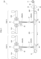
- Fig. 1 is a schematic view illustrating an example of an apparatus for manufacturing the spunbonded non-woven fabric layered body of the present disclosure.
- the spunbonding manufacturing apparatus 100 illustrated in Fig. 1 includes a first spinning unit 11A and a second spinning unit 11B.
- the first spinning unit 11A and the second spinning unit 11B include the same component portions.
- the same component portions in the first spinning unit 11A and the second spinning unit 11B are denoted by the same reference characters, and the descriptions thereof are omitted.
- the spunbonding manufacturing apparatus 100 includes first extruders 31A that extrude a thermoplastic polymer, second extruders 31B that extrude a plastic polymer, spinnerets 33 that melt-spin melted thermoplastic polymers, ejectors 37 that draw continuous fiber assemblies 20 (20A, 20B) melt-spun from the spinnerets 33, a movable trapping member 51 that traps the drawn continuous fiber assemblies 20, suction units 39 for efficiently trapping the continuous fiber assemblies 20 on the movable trapping member 51, an embossing roll 53 and a flat roll 55 for thermocompression bonding, and a winder 71 that winds a spunbonded non-woven fabric layered body 60 subjected to the thermocompression bonding.
- the thermoplastic polymer is melt-spin from the spinneret 33, to form the continuous fiber assembly 20A, in the first spinning unit 11A.
- the continuous fiber assembly 20A is a crimped continuous fiber assembly
- a first thermoplastic polymer may be extruded from the first extruder 31A
- a second thermoplastic polymer may be extruded from the second extruder 31B
- composite spinning may be performed.
- the continuous fiber assembly 20A is cooled by cooling air 35, and is drawn by the ejector 37.
- the drawn continuous fiber assembly 20A is efficiently trapped on the movable trapping member 51 by the suction unit 39 disposed in the lower portion of the trapping face of the movable trapping member 51, to form a first non-woven web 40A.
- the continuous fiber assembly 20B is also formed in a similar manner.
- the continuous fiber assembly 20B is layered on the first non-woven web 40A, whereby a second non-woven web 40B is formed to form a non-woven web having a layered structure.
- the first non-woven web 40A is a lower-layer non-woven web layer
- the second non-woven web 40B is an upper-layer non-woven web.
- the non-woven web having the layered structure is thermocompression-bonded by the embossing roll 53 and the flat roll 55, to obtain the spunbonded non-woven fabric layered body 60. Then, the spunbonded non-woven fabric layered body 60 is wound by the winder 71.
- Thermocompression bonding using an embossing roll satisfying the following (1) to (3) as the embossing roll 53 is preferred for satisfying the above-described conditions (A) to (C), and (E) and (F), in the spunbonded non-woven fabric satisfying the condition (D) described above.
- the details of the embossing roll will be described later.
- a spinning unit 11 may be included, or two or more spinning units 11 may be included. Both or either of a first extruder 31A and a second extruder 31B may be used.
- the manufacture may be performed in a manufacturing apparatus including a spinning unit 12 in which a cooling chamber illustrated in Fig. 2 has a closed-type structure.
- Fig. 2 is a schematic view illustrating another example of the apparatus for manufacturing the spunbonded non-woven fabric layered body of the present disclosure.
- Fig. 2 illustrates the apparatus in which the spinning units 11 (the spinning unit 11A and the spinning unit 11B) in the spunbonding manufacturing apparatus 100 illustrated in Fig. 1 are replaced with the spinning unit 12.
- the apparatus configuration other than the spinning units 11 is identical to that of the manufacturing apparatus illustrated in Fig. 1 .
- the same component portions as those of the manufacturing apparatus illustrated in Fig. 1 are denoted by the same reference characters, and the descriptions thereof are omitted.
- the spinning unit 12 includes a first extruder 32 that extrudes a thermoplastic polymer, a spinneret 34 that melt-spins a melted thermoplastic polymer, a cooling chamber 38C that cools a continuous fiber assembly 22 melt-spun from the spinneret 34, cooling air supply units 38A and 38B that supply cooling air 36, and a drawing unit 38D that draws the continuous fiber assembly 22.
- the thermoplastic polymer is extruded to introduce the melted thermoplastic polymer into the spinneret 34. Then, the melted thermoplastic polymer is melt-spun from the spinneret 34.
- the melt-spun continuous fiber assembly 22 is introduced into the cooling chamber 38C.
- the continuous fiber assembly 22 is cooled by the cooling air 36 supplied from either or both of the cooling air supply unit 38A and the cooling air supply unit 38B.
- the cooled continuous fiber assembly 22 is introduced into the drawing unit 38D included downstream of the cooling chamber 38C.
- the drawing unit 38D is disposed in a bottleneck shape. The continuous fiber assembly 22 introduced into the drawing unit 38D is drawn by increasing the velocity of the cooling air in the bottleneck.
- the drawn continuous fiber assembly 22 is dispersed and trapped on a movable trapping member 51.
- the dispersed continuous fiber assembly 22 is efficiently trapped on the movable trapping member 51 by a suction unit 39 included in the lower portion of the trapping face of movable trapping member 51, to form a non-woven web 42.
- the other example of the method of manufacturing the spunbonded non-woven fabric of the present disclosure has been described with reference to Fig. 2 .
- the invention is not limited thereto. Only one spinning unit 12 may be included, or two or more spinning units 12 may be included. In Fig. 2 , only the one extruder 32 is included. However, two or more extruders 32 may be included.
- the continuous fiber assemblies 20 melt-spun from the spinnerets 33 illustrated in Fig. 1 and the continuous fiber assembly 22 melt-spun from the spinneret 34 illustrated in Fig. 2 may be crimped continuous fiber assemblies.
- the melt-spun continuous fiber assembly is a crimped continuous fiber assembly
- the thermoplastic polymer may contain a first thermoplastic polymer component and a second thermoplastic polymer component of which the melting point is higher than that of the first thermoplastic polymer component by 5°C or more, and the first thermoplastic polymer component and the second thermoplastic polymer component may be compositely melt-spun.
- the non-woven web may be a layered non-woven web with two or more layers, depending on a purpose.
- a second non-woven web may be formed by depositing a first continuous fiber assembly on the movable trapping member to form a first non-woven web, and then depositing a second continuous fiber assembly on the first non-woven web.
- both the first non-woven web and the second non-woven web include crimped fibers, it is easy to obtain a spunbonded non-woven fabric layered body that satisfies the conditions (A) to (F) described above.
- non-woven web is a concept encompassing not only a non-woven web with a single layer but also a layered non-woven web.
- a temperature at which the non-woven web is thermocompression-bonded may be set depending on a fiber included in the non-woven web.
- the temperature may be in a range of from 100°C to 200°C.
- a linear pressure in the case of the thermocompression bonding include a linear pressure of from 100 N/cm to 1500 N/cm.
- a pressure bonding velocity in the case of the thermocompression bonding include a pressure bonding velocity of from 1 m/sec to 50 m/sec.
- a projection and a recess are disposed on the embossing roll, and it is important to satisfy the following (1) to (3).
- a case in which the embossing roll satisfies the above (1) to (3) represents that the area of the top face of the projection is small, the projection is high, the projection has high hardness, and the embossing roll includes an appropriate amount of projections.
- the case represents that the embossing roll is provided with an appropriate amount of hard projections having long and narrow shapes.
- the projections are prone to be damaged, thereby resulting in poor productivity. Therefore, it is difficult to obtain the above-described spunbonded non-woven fabric that is bulky and excellent in flexibility.
- thermocompression bonding by the embossing roll satisfying all of the above (1) to (3) is useful for efficiently producing the spunbonded non-woven fabric that satisfies the above-described conditions (A) to (D) because of resulting in suppression of damage to projections disposed on the embossing roll.
- the preferred lower limit of the area ratio of the projection is 7% or more in view of obtaining the spunbonded non-woven fabric that is bulky and excellent in flexibility.
- the preferred upper limit of the area ratio of the projection is 15% or less.
- An emboss aspect ratio of less than 2.5 mm/mm 2 makes it difficult to obtain the spunbonded non-woven fabric that is bulky and excellent in flexibility. It is difficult to manufacture an embossing roll having an emboss aspect ratio of more than 7.0 mm/mm 2 .
- the preferred upper limit of the emboss aspect ratio is 6.0 mm/mm 2 or less, and the more preferred upper limit of the emboss aspect ratio is 5.5 mm/mm 2 or less, from the viewpoint of manufacturing the spunbonded non-woven fabric that is bulky and excellent in flexibility and that has small flexural rigidity.
- the preferred lower limit of the emboss aspect ratio is 3.0 mm/mm 2 or more, and the more preferred lower limit of the emboss aspect ratio is 3.5 mm/mm 2 or more.
- the base material of the embossing roll may have a Rockwell hardness of 35 HRC or more, preferably from 35 HRC to 50 HRC, from the viewpoint of obtaining the spunbonded non-woven fabric that is bulky and excellent in flexibility and that has small flexural rigidity.
- the Rockwell hardness of the base material of the embossing roll is 35 HRC or more, the spunbonded non-woven fabric that is bulky and excellent in flexibility can be efficiently manufactured.
- a method of manufacturing the embossing roll satisfying all the conditions (1) to (3) described above is not particularly limited, and the embossing roll is manufactured by a known method. Examples thereof include a method of obtaining an embossing roll satisfying the conditions (1) and (2) by subjecting a surface of a base material satisfying the condition (3) to treatment such as engraving treatment, electroforming treatment, sandblast treatment, electrical-discharge machining treatment, or etching treatment.
- the ratio of a depth to the bottom face of the recess with respect to a distance between the projections adjacent to each other in a rotation direction is preferably from 0.4 mm/mm to 1.0mm/mm, from the viewpoint of obtaining the spunbonded non-woven fabric that is bulky and excellent in flexibility and that has small flexural rigidity.
- the more preferred lower limit of the ratio is 0.5 mm/mm or more, and the more preferred upper limit of the ratio is 0.8 mm/mm.
- the distance between the projections adjacent to each other in a rotation direction represents a center distance between the projections adjacent to each other (also referred to as "projection pitch") (see Fig. 3 ).
- the projection pitch is preferably from 0.5 mm to 3.0 mm from the viewpoint of obtaining the spunbonded non-woven fabric that is bulky and excellent in flexibility and that has small flexural rigidity.
- the area of the top face of the projection is preferably from 0.1 mm 2 to 1.0 mm 2 from a similar viewpoint.
- the shape of the top face of the projection of the embossing roll is not particularly limited.
- a round shape, an elliptical shape, a triangular shape, a quadrangular shape, a rhombic shape, or a pentagonal or more polygonal shape is acceptable. Shapes surrounded by these shapes are also acceptable. Combinations of these shapes are also acceptable.
- Fig. 3 is a schematic view illustrating the example of the embossing roll of the present disclosure.
- the embossing roll 200 includes a large number of projections 201A and projections 201B.
- the projections 201A and the projections 201B are disposed in the same shape, and the top faces of the projections 201A and the projections 201B have the same elliptical shape.
- recesses 203 are disposed between the projection 201A and the projection 201A adjacent to each other, between the projection 201A and the projection 201B adjacent to each other, and between the projection 201B and the projection 201B adjacent to each other.
- the projection group of the projections 201A is arranged so that the orientations of the ellipses of the projections 201A are identical in the direction of rotating the embossing roll, and so that the orientations of the ellipses are identical on alternate lines.
- the projection group of the projections 201B is also disposed in an arrangement similar to the arrangement of the projection group of the proj ections 201A.
- the projection group of the projections 201A and the projection group of the projections 201B are disposed so that the arrangement orientations thereof alternate in each line in the rotation direction.
- the projection group of the projections 201A is disposed to have a distance P (i.e., a projection pitch P) between the projections adjacent to each other in the rotation direction, as illustrated in Fig. 3 .
- the distance P between the projections adjacent to each other in the rotation direction is a center distance between the ellipses.
- the center of the ellipse represents a point of intersection of the shortest diameter and the longest diameter.
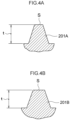
- Fig. 4A is a cross-sectional view taken along the line A-A in the projection included in the embossing roll illustrated in Fig. 3 . Specifically, the cross-sectional view taken along the line A-Ain the projection 201Aincluded in the embossing roll 200 is illustrated.
- Fig. 4B is a cross-sectional view taken along the line B-B in the projection included in the embossing roll illustrated in Fig. 3 . Specifically, the cross-sectional view taken along the line B-B in the projection 201B included in the embossing roll 200 is illustrated.
- Fig. 5 is a perspective view of the projections included in the embossing roll illustrated in Fig. 3 , viewed from the rotation direction.
- each of the projections 201A and the projections 201B has a taper angle.
- each of the projections 201A and the projections 201B has a depth t from the top face of each of the projections 201A and the projections 201B to the bottom face of each of the recesses 203, and has the area S of the top face.
- the ratio (t/P) of the depth t to the bottom face of the recess 203 with respect to the distance P between projections 201A adjacent to each other in the rotation direction is preferably in the range described above.
- the emboss aspect ratio represented by the ratio (t/S) between the area S of the top face of the projection 201A and the depth t from the top face of the projection 201A to the bottom face of the recess 203 is preferably in the range described above.
- the depth t from the top face of the projection 201A to the bottom face of the recess 203 is not particularly limited as long as the emboss aspect ratio is in a range satisfying the range described above.
- the above descriptions have been given mainly with reference to the projections 201A. However, the same also applies to the projections 201B.
- the embossing roll of the present disclosure is preferred for thermocompression-bonding the non-woven web for obtaining the spunbonded non-woven fabric and spunbonded non-woven fabric layered body of the present disclosure.
- the embossing roll of the present disclosure is not limited thereto, and can also be applied to a non-woven web other than the spunbonded non-woven fabric and the spunbonded non-woven fabric layered body as long as the non-woven web can be thermocompression-bonded.
- spunbonded non-woven fabric of the present disclosure will be described below with reference to Examples. However, the spunbonded non-woven fabric of the present disclosure is not limited at all to the following embodiments.
- test pieces of 100 mm (machine direction: MD) ⁇ 100 mm (direction orthogonal to machine direction: CD) were cut from a spunbonded non-woven fabric. Places at which the test pieces were cut were set at ten places in the CD direction. Then, the mass[g] of each cut test piece was measured using an electronic balance scale (manufactured by Kensei Co., LTD.) under an environment of 20°C and a relative humidity of 50% RH. The average value of the masses of the test pieces was calculated. The calculated average value was converted into a mass [g] per m 2 , which was rounded off to one decimal place to obtain a value, which was regarded as the basis weight [g/m 2 ] of each non-woven fabric sample.
- MD machine direction
- CD direction orthogonal to machine direction
- test pieces of 100 mm (MD) ⁇ 100 mm (CD) were cut from a spunbonded non-woven fabric. Places at which the test pieces were cut were set at places similar to the test pieces for measuring the basis weight. Then, the thickness [mm] of each cut test piece was measured by a method described in JIS L 1096: 2010, using a load-type thickness gauge (manufactured by OZAKI MFG. CO., LTD.). The average value of the thicknesses of the test pieces was calculated, and rounded off to one decimal place to obtain a value, which was regarded as the thickness [mm] of each non-woven fabric sample.
- test pieces of 150 mm (MD) ⁇ 150 mm (CD) were cut from a non-woven fabric. Cutting places were set at two places in the CD direction. Then, the test pieces were subjected to a compression test at a compressive deformation velocity of 0.020 mm/sec and a maximum pressure of 50 gf/cm 2 , using a compression test probe (a steel pressure plate having a circular plane having a compression area of 2 cm 2 ), under an environment of 20°C and relative humidity of 50% RH as measurement conditions, by a compression testing machine KES-FB3-A manufactured by KATO TECH CO., LTD., to measure WC [gf ⁇ cm/cm 2 ].
- the average value of WC of the test pieces was calculated, and rounded off to two decimal places to obtain a value, which was regarded as WC [gf ⁇ cm/cm 2 ] of each non-woven fabric sample.
- test pieces of 150 mm (MD) ⁇ 150 mm (CD) were cut from a non-woven fabric. Cutting places were set at two places in the CD direction. Then, the test pieces were subjected to a compression test at a compressive deformation velocity of 0.020 mm/sec and a maximum pressure of 50 gf/cm 2 , using a compression test probe (a steel pressure plate having a circular plane having a compression area of 2 cm 2 ), under an environment of 20°C and relative humidity of 50% RH as measurement conditions, by a compression testing machine KES-FB3-A manufactured by KATO TECH CO., LTD., to measure TO [mm] and TM [mm].
- a compression testing machine KES-FB3-A manufactured by KATO TECH CO., LTD.
- the average value of TO [mm] and TM [mm] of the test pieces was calculated, and rounded off to two decimal places to obtain values, which were regarded as TO [mm] and TM [mm] of each non-woven fabric sample.
- the TO-TM [mm] of each non-woven fabric sample was calculated.
- the bending resistance (mm) of a spunbonded non-woven fabric was measured by performing a cantilever test according to the following method, thereby evaluating the flexural rigidity. Specifically, the measurement was performed in compliance with JIS-L1096: 2010, chapter 8.19.1 (the A method (45° cantilever method)).
- test piece obtained was placed on a horizontal table that had a smooth surface and that was provided with a slope at an inclination of 45° at one end thereof, such that a shorter side of the test piece was positioned on the baseline of the scale. Then, the test piece was gently slid towards the slope by an appropriate method, and, when the center point of one end of the test piece contacted the slope, the position of the other end of the test piece on the scale was read.
- the bending resistance is expressed as the distance (mm) for which the test piece has moved.
- the bending resistance was measured for the 5 sheets for the machine direction and the 5 sheets for the cross direction, and an average value of the bending resistance values was obtained for each of the machine direction and the cross direction.
- the average bending resistance in the machine direction was taken as BR MD
- the average bending resistance in the cross direction was taken as BR CD .
- the following first component and the following second component were compositely melt-spun by spunbonding, and a lower-layer non-woven web formed of side-by-side type crimped fibers (hereinafter referred to as "crimped fibers A") was deposited on a movable trapping face.
- the side-by-side type crimped fibers have a first component/second component mass ratio of 40/60 and an average fiber diameter of 15 ⁇ m.
- the basis weight of the non-woven web was 11.4 g/m 2 .
- the MFR is measured at a temperature of 230°C and a load of 2.16 kg according to ASTM D1238, and the same method is applied unless otherwise noted.
- Propylene-ethylene random copolymer having a melting point of 142°C and an MFR of 60 g/10 minutes.
- the following first component and the following second component were compositely melt-spun by spunbonding, and an upper-layer non-woven web formed of side-by-side type crimped fibers (hereinafter referred to as "crimped fibers B") was deposited on the lower-layer non-woven web in an in-line manner to produce a non-woven web having a layered structure.
- the side-by-side type crimped fibers have a first component/second component mass ratio of 20/80 and an average fiber diameter of 15 ⁇ m.
- the basis weight of the non-woven web was 5.6 g/m 2 .
- Propylene homopolymer having a melting point of 162°C and an MFR of 60 g/10 minutes
- Propylene-ethylene random copolymer having a melting point 142°C and an MFR of 60 g/10 minutes
- the non-woven web having the layered structure was heat-sealed under the following embossment conditions by the following embossing roll, to obtain a spunbonded non-woven fabric layered body having a total basis weight of 17 g/m 2 .
- the area ratio of a pressure bonding portion was 11%.
- a spunbonded non-woven fabric layered body was obtained in a similar manner to Example 1 except that the basis weight of a lower layer in the spunbonded non-woven fabric layered body was 13.4 g/m 2 , the basis weight of an upper layer was 6.6 g/m 2 , and a total basis weight was 20 g/m 2 .
- a spunbonded non-woven fabric layered body was obtained in a similar manner to Example 1 except that the basis weight of a lower layer in the spunbonded non-woven fabric layered body was 15.4 g/m 2 , the basis weight of an upper layer was 7.6 g/m 2 , and a total basis weight was 23 g/m 2 .
- a spunbonded non-woven fabric layered body was obtained in a similar manner to Example 2 except that the following embossing roll was used as an embossing roll.
- a spunbonded non-woven fabric layered body was obtained in a similar manner to Example 1 except that the following embossing roll was used as an embossing roll.
- a spunbonded non-woven fabric layered body was obtained in a similar manner to Example 2 except that the following embossing roll was used as an embossing roll.
- a spunbonded non-woven fabric layered body was obtained in a similar manner to Example 1 except that the basis weight of a lower layer in the spunbonded non-woven fabric layered body was 20.0 g/m 2 , the basis weight of an upper layer was 10.0 g/m 2 , a total basis weight was 30 g/m 2 , the following embossing roll was used as an embossing roll, and the following embossment conditions were set. The area ratio of a pressure bonding portion was 11%. In this case, the spunbonded non-woven fabric layered body was obtained; however, since the hardness of an embossment base material was insufficient, a facility defect was caused, and it was impossible to obtain sufficient mass production stability.
- a spunbonded non-woven fabric layered body was obtained in a similar manner to Example 1 except that an upper layer in the spunbonded non-woven fabric layered body was a non-woven web including non-crimped fibers (referred to as "non-crimped fibers A") using only a second component, and a lower layer was a non-woven web including non-crimped fibers (referred to as "non-crimped fibers B") using only a second component.
- non-crimped fibers A non-crimped fibers
- non-crimped fibers B non-woven web including non-crimped fibers
- Propylene-ethylene random copolymer having a melting point of 142°C and an MFR of 60 g/10 minutes
- Propylene-ethylene random copolymer having a melting point of 142°C and an MFR of 60 g/10 minutes
- a spunbonded non-woven fabric layered body was obtained in a similar manner to Example 2 except that an upper layer in the spunbonded non-woven fabric layered body was a non-woven web including non-crimped fibers (referred to as "non-crimped fibers A") using the following component, and a lower layer was a non-woven web including non-crimped fibers (referred to as "non-crimped fibers B") using the following component.
- non-crimped fibers A non-woven web including non-crimped fibers
- non-crimped fibers B a non-woven web including non-crimped fibers
- Propylene-ethylene random copolymer having a melting point of 142°C and an MFR of 60 g/10 minutes
- Propylene-ethylene random copolymer having a melting point of 142°C and an MFR of 60 g/10 minutes
- a spunbonded non-woven fabric layered body was obtained in a similar manner to Example 2 except that an upper layer in the spunbonded non-woven fabric layered body was a non-woven web including non-crimped fibers (referred to as "non-crimped fibers C") using the following component, a lower layer was a non-woven web including non-crimped fibers (referred to as “non-crimped fibers D") using the following component, and embossment conditions were the following conditions.
- Propylene homopolymer having a melting point of 162°C and an MFR of 60 g/10 minutes
- Propylene homopolymer having a melting point of 162°C and an MFR of 60 g/10 minutes
- a spunbonded non-woven fabric layered body was obtained in a similar manner to Example 1 except that the basis weight of a lower layer in the spunbonded non-woven fabric layered body was 10.0 g/m 2 , the basis weight of an upper layer was 10.0 g/m 2 , a total basis weight was 20 g/m 2 , and the upper layer was a non-woven web including non-crimped fibers (referred to as "non-crimped fibers A”) using the following component.
- each Example exhibits a basis weight W, a thickness t, WC measured by a KES method, TO-TM measured by the KES method, a bending resistance BR MD , and a bending resistance BR CD within the ranges of the spunbonded non-woven fabric (non-woven fabric layered body) of the present disclosure, and is found to be bulky and excellent in flexibility and have small flexural rigidity.
- Spunbonded non-woven fabrics of Comparative Examples 8 and 9 are commercially available products that are composed of non-crimped fibers and that have bulkiness imparted by subjecting spunbonded non-woven fabrics after embossing treatment to treatment using a processing apparatus or the like. The results obtained are indicated in Table 2.
- Comparative Example 8 Comparative Example 9 Evaluations kind of Fibers Non-Crimped Non-Crimped Total Basis Weight W (g/m 2 ) 20 16 Thickness t (mm) 0.91 0.53 WC (gf ⁇ cm/cm 2 ) 0.80 0.54 TO-TM (mm) 0.90 0.51 BR MD (mm) 53 41 BR CD (mm) 35 23
- spunbonded non-woven fabrics according to the Examples were able to achieve excellent bulkiness and flexibility as well as small flexural rigidity.
Claims (15)
- Spinnvliesstoff, umfassend eine Faser eines thermoplastischen Polymers, wobei der Stoff eine Dicke t, eine Kompressionsarbeit WC, gemessen in einem Kompressionstest nach einem KES-Verfahren, eine Dicke TO, gemessen in dem Kompressionstest nach dem KES-Verfahren bei einem Druck von 0.5 gf/cm2, eine Dicke TM, gemessen in dem Kompressionstest nach dem KES-Verfahren bei einem Druck von 50 gf/cm2, ein Flächengewicht W und einen Biegewiderstand BRMD in einer Maschinenrichtung (MD) und einen Biegewiderstand BRCD in einer Querrichtung, gemessen gemäß einer in JIS-L1096: 2010 definierten 45°-Cantilever-Methode, die die folgenden Bedingungen (A) bis (F) erfüllen:(A): t ≥ 0,30mm;(B): WC ≥ 0,22 gf·cm/cm2;(C): TO-TM ≥ 0,25 mm;(D): W ≤ 30 g/m2;(E): BRMD ≤ 40 mm; und(F): BRCD ≤ 25 mm,wobei die Faser eine gekräuselte Faser umfasst undder Spinnvliesstoff durch ein Verfahren erhältlich ist, umfassend:das Schmelzspinnen eines thermoplastischen Polymers, um eine Endlosfaseranordnung zu bilden;das Ablegen der gebildeten Endlosfaseranordnung auf einem beweglichen Fangelement, um eine Vliesstoffbahn zu bilden; unddas Durchführen einer Thermokompressionsverbindung der gebildeten Vliesstoffbahn mittels einer Prägewalze, an der ein Vorsprung und eine Vertiefung angeordnet sind, und bei der ein Flächenanteil des Vorsprungs 5% bis 18% beträgt, ein Prägeseitenverhältnis, dargestellt durch ein Verhältnis von einer Tiefe von einer Oberseite des Vorsprungs bis zu einer Unterseite der Vertiefung zu einer Fläche der Oberseite des Vorsprungs, 2,5 mm/mm2 bis 7,0 mm/mm2 beträgt, und ein Basismaterial eine Rockwell-Härte von 35 HRC oder mehr aufweist.
- Spinnvliesstoff gemäß Anspruch 1, ferner umfassend einen Druckverbindungsbereich und einen Nicht-Druckverbindungsbereich.
- Spinnvliesstoff gemäß Anspruch 2, wobei ein Flächenanteil des Druckverbindungsbereichs 5% und 18% beträgt.
- Spinnvliesstoff gemäß einem der Ansprüche 1 bis 3, wobei das thermoplastische Polymer ein olefinisches Polymer umfasst.
- Spinnvliesstoff gemäß Anspruch 4, wobei das olefinische Polymer ein propylenbasiertes Polymer umfasst.
- Spinnvliesstoff gemäß einem der Ansprüche 1 bis 5, wobei die Faser einen durchschnittlichen Faserdurchmesser von 5 µm bis 20 µm aufweist.
- Spinnvliesstoff gemäß einem der Ansprüche 1 bis 6, der in einem Sanitärmaterial verwendet wird.
- Spinnvliesstoff gemäß einem der Ansprüche 1 bis 7, wobei der Spinnvliesstoff ein Spinnvlies-Schichtkörper ist.
- Verfahren zur Herstellung des Spinnvliesstoffs gemäß einem der Ansprüche 1 bis 8, umfassend:das Schmelzspinnen eines thermoplastischen Polymers, um eine Endlosfaseranordnung zu bilden;das Ablegen der gebildeten Endlosfaseranordnung auf einem beweglichen Fangelement, um eine Vliesstoffbahn zu bilden; unddas Durchführen einer Thermokompressionsverbindung der gebildeten Vliesstoffbahn mittels einer Prägewalze, an der ein Vorsprung und eine Vertiefung angeordnet sind, und bei der ein Flächenanteil des Vorsprungs 5% bis 18% beträgt, ein Prägeseitenverhältnis, dargestellt durch ein Verhältnis von einer Tiefe von einer Oberseite des Vorsprungs bis zu einer Bodenseite der Vertiefung zu einer Fläche der Oberseite des Vorsprungs, 2,5 mm/mm2 bis 7,0 mm/mm2 beträgt, und ein Basismaterial eine Rockwell-Härte von 35 HRC oder mehr aufweist.
- Verfahren zur Herstellung des Spinnvlieses gemäß Anspruch 9, wobei das Basismaterial der Prägewalze eine Rockwell-Härte von 35 HRC bis 50 HRC aufweist.
- Verfahren zur Herstellung eines Spinnvlieses gemäß Anspruch 9 oder 10, wobei ein Verhältnis von der Tiefe zu einem Abstand zwischen in Drehrichtung nebeneinander liegenden Vorsprüngen 0,4 mm/mm bis 1,0 mm/mm beträgt.
- Verfahren zur Herstellung des Spinnvlieses gemäß einem der Ansprüche 9 bis 11, wobei die Vliesstoffbahn eine Vliesstoffbahn mit mindestens zwei Schichten ist.
- Prägewalze zum Durchführen einer Thermokompressionsverbindung einer Vliesstoffbahn,
wobei ein Vorsprung und eine Vertiefung auf der Walze angeordnet sind, ein Flächenanteil des Vorsprungs 5% bis 18% beträgt, ein Prägeseitenverhältnis, dargestellt durch ein Verhältnis von einer Tiefe von einer Oberseite des Vorsprungs bis zu einer Bodenseite der Vertiefung zu einer Fläche der Oberseite des Vorsprungs, 2,5 mm/mm2 bis 7,0 mm/mm2 beträgt, und ein Basismaterial eine Rockwell-Härte von 35 HRC oder mehr aufweist. - Prägewalze gemäß Anspruch 13, wobei das Basismaterial der Prägewalze eine Rockwellhärte von 35 HRC bis 50 HRC aufweist.
- Prägewalze gemäß Anspruch 13 oder 14, wobei das Verhältnis von der Tiefe zu einem Abstand zwischen in Drehrichtung nebeneinander liegenden Vorsprüngen 0,4 mm/mm bis 1,0 mm/mm beträgt.
Applications Claiming Priority (2)
| Application Number | Priority Date | Filing Date | Title |
|---|---|---|---|
| PCT/JP2019/002536 WO2020152863A1 (ja) | 2019-01-25 | 2019-01-25 | スパンボンド不織布、スパンボンド不織布の製造方法、エンボスロール |
| PCT/JP2019/030966 WO2020152890A1 (ja) | 2019-01-25 | 2019-08-06 | スパンボンド不織布、スパンボンド不織布の製造方法、エンボスロール |
Publications (3)
| Publication Number | Publication Date |
|---|---|
| EP3715519A1 EP3715519A1 (de) | 2020-09-30 |
| EP3715519A4 EP3715519A4 (de) | 2021-04-07 |
| EP3715519B1 true EP3715519B1 (de) | 2023-11-29 |
Family
ID=67539823
Family Applications (1)
| Application Number | Title | Priority Date | Filing Date |
|---|---|---|---|
| EP19802023.2A Active EP3715519B1 (de) | 2019-01-25 | 2019-08-06 | Spinnvliesstoff, verfahren zur herstellung eines spinnvliesstoffes und prägewalze |
Country Status (6)
| Country | Link |
|---|---|
| EP (1) | EP3715519B1 (de) |
| JP (2) | JP6557440B1 (de) |
| KR (1) | KR102552774B1 (de) |
| CN (1) | CN113348277B (de) |
| DK (1) | DK3715519T3 (de) |
| WO (2) | WO2020152863A1 (de) |
Families Citing this family (2)
| Publication number | Priority date | Publication date | Assignee | Title |
|---|---|---|---|---|
| US20230119832A1 (en) * | 2020-03-31 | 2023-04-20 | Mitsui Chemicals, Inc. | Nonwoven fabric layered body, cover sheet, and absorbent article |
| CN114622341A (zh) * | 2020-12-15 | 2022-06-14 | 浙江青昀新材料科技有限公司 | 一种聚乙烯无纺布及其应用 |
Family Cites Families (24)
| Publication number | Priority date | Publication date | Assignee | Title |
|---|---|---|---|---|
| JPS57112454A (en) * | 1980-12-29 | 1982-07-13 | Asahi Chemical Ind | Nonwoven fabric |
| JPS57167442A (en) | 1981-04-07 | 1982-10-15 | Chisso Corp | Production of nonwoven fabric |
| JPH01201567A (ja) | 1988-01-30 | 1989-08-14 | Asahi Chem Ind Co Ltd | 嵩高スパンボンド不織布の製造方法 |
| JP2793591B2 (ja) | 1988-03-04 | 1998-09-03 | 三井化学株式会社 | エンボス加工されたスパンボンド不織布とそのエンボス加工方法 |
| JPH10280267A (ja) * | 1997-04-08 | 1998-10-20 | Mitsui Chem Inc | 柔軟性スパンボンド不織布 |
| JP4007685B2 (ja) * | 1998-06-11 | 2007-11-14 | 三井化学株式会社 | 吸収性物品用トップシート材 |
| JP2001140158A (ja) * | 1999-11-09 | 2001-05-22 | Chisso Corp | 伸縮性複合化不織布及びこれを用いた吸収性物品 |
| JP2001315268A (ja) * | 2000-05-09 | 2001-11-13 | Uni Charm Corp | 通気不透液性複合シート |
| US20030041953A1 (en) * | 2001-08-31 | 2003-03-06 | Bba Nonwovens Simpsonville, Inc. | Method of making a bonded nonwoven web |
| JP3993452B2 (ja) * | 2002-03-29 | 2007-10-17 | ユニ・チャーム株式会社 | 薄型の吸収性物品およびその製造方法 |
| CN100575584C (zh) * | 2002-09-26 | 2009-12-30 | 旭化成纤维株式会社 | 纺粘类无纺布及卫生材料 |
| JP4716638B2 (ja) * | 2002-09-26 | 2011-07-06 | 旭化成せんい株式会社 | 柔軟な衛生材料用不織布及び使い捨て衛生材料 |
| JP4213989B2 (ja) * | 2003-05-08 | 2009-01-28 | 富士フイルム株式会社 | 防眩性フィルムの製造方法 |
| US7438777B2 (en) * | 2005-04-01 | 2008-10-21 | North Carolina State University | Lightweight high-tensile, high-tear strength bicomponent nonwoven fabrics |
| EP1983082B1 (de) | 2006-02-06 | 2013-09-18 | Mitsui Chemicals, Inc. | Spinnvlies |
| JP5486243B2 (ja) * | 2009-08-31 | 2014-05-07 | 旭化成せんい株式会社 | ポリオレフィン系捲縮長繊維不織布及び不織布積層体 |
| JP5704877B2 (ja) | 2010-09-30 | 2015-04-22 | ユニ・チャーム株式会社 | 不織布、及び上記不織布を含む吸収性物品、並びに上記不織布の形成方法 |
| US20150233031A1 (en) * | 2012-09-27 | 2015-08-20 | Mitsui Chemicals, Inc. | Spunbond nonwoven fabric |
| JP6115146B2 (ja) * | 2013-01-22 | 2017-04-19 | 王子ホールディングス株式会社 | スパンボンド不織布 |
| JP6560015B2 (ja) * | 2014-05-30 | 2019-08-14 | 花王株式会社 | 使い捨ておむつ |
| JP6714982B2 (ja) * | 2014-08-15 | 2020-07-01 | 旭化成株式会社 | 嵩高性複合長繊維不織布 |
| JP6038196B2 (ja) * | 2015-01-09 | 2016-12-07 | ユニ・チャーム株式会社 | 不織布、及び上記不織布を含む吸収性物品、並びに上記不織布の形成方法 |
| US20180369737A1 (en) * | 2015-12-22 | 2018-12-27 | Toray Industries, Inc. | Spunbond nonwoven fabric for filter and method of manufacturing said fabric |
| KR102564088B1 (ko) * | 2019-03-27 | 2023-08-07 | 미쓰이 가가쿠 가부시키가이샤 | 부직포 적층체 및 위생 용품 |
-
2019
- 2019-01-25 WO PCT/JP2019/002536 patent/WO2020152863A1/ja active Application Filing
- 2019-01-25 JP JP2019507875A patent/JP6557440B1/ja active Active
- 2019-08-06 EP EP19802023.2A patent/EP3715519B1/de active Active
- 2019-08-06 JP JP2020567355A patent/JP7246415B2/ja active Active
- 2019-08-06 DK DK19802023.2T patent/DK3715519T3/da active
- 2019-08-06 WO PCT/JP2019/030966 patent/WO2020152890A1/ja unknown
- 2019-08-06 CN CN201980089526.2A patent/CN113348277B/zh active Active
- 2019-08-06 KR KR1020217022937A patent/KR102552774B1/ko active IP Right Grant
Also Published As
| Publication number | Publication date |
|---|---|
| JP6557440B1 (ja) | 2019-08-07 |
| CN113348277A (zh) | 2021-09-03 |
| WO2020152863A1 (ja) | 2020-07-30 |
| CN113348277B (zh) | 2023-08-01 |
| JPWO2020152863A1 (ja) | 2021-02-18 |
| KR20210094670A (ko) | 2021-07-29 |
| JP7246415B2 (ja) | 2023-03-27 |
| DK3715519T3 (da) | 2024-02-12 |
| JPWO2020152890A1 (ja) | 2021-11-25 |
| WO2020152890A1 (ja) | 2020-07-30 |
| KR102552774B1 (ko) | 2023-07-06 |
| EP3715519A1 (de) | 2020-09-30 |
| EP3715519A4 (de) | 2021-04-07 |
Similar Documents
| Publication | Publication Date | Title |
|---|---|---|
| EP2650419B2 (de) | Schmelzgeblasener vliesstoff sowie verfahren und vorrichtung zu seiner herstellung | |
| EP2708623B1 (de) | Gekräuselte verbundfaser und vliesstoff mit der faser | |
| KR101533167B1 (ko) | 스펀본드 부직포 적층체 | |
| EP2677074B1 (de) | Spinnfaservlies | |
| EP3715519B1 (de) | Spinnvliesstoff, verfahren zur herstellung eines spinnvliesstoffes und prägewalze | |
| EP3950303A1 (de) | Laminierter vliesstoffkörper und hygieneprodukt | |
| JP2023126282A (ja) | 不織布積層体、並びに、伸縮性不織布積層体、繊維製品、吸収性物品及び衛生マスク | |
| EP3725928A1 (de) | Spinnvliesstoff, hygienematerial und verfahren zur herstellung von spinnvliesstoff | |
| JP2019026955A (ja) | スパンボンド不織布 | |
| EP3901346B1 (de) | Spinnvliesstoff, sanitärartikel und verfahren zur herstellung eines spinnvliesstoffs | |
| EP3722477B1 (de) | Verfahren zur herstellung von spinnvliesstoff und spinnvliesstoff | |
| WO2019021809A1 (ja) | 捲縮繊維、スパンボンド不織布、およびそれらの製造方法 | |
| EP3779016B1 (de) | Vliesstofflaminat, dehnbares vliesstofflaminat, sowie textilprodukt | |
| JP2022135776A (ja) | 不織布、不織布積層体及び吸収性物品 | |
| WO2023069412A1 (en) | High loft nonwoven fabrics |
Legal Events
| Date | Code | Title | Description |
|---|---|---|---|
| STAA | Information on the status of an ep patent application or granted ep patent |
Free format text: STATUS: UNKNOWN |
|
| STAA | Information on the status of an ep patent application or granted ep patent |
Free format text: STATUS: THE INTERNATIONAL PUBLICATION HAS BEEN MADE |
|
| PUAI | Public reference made under article 153(3) epc to a published international application that has entered the european phase |
Free format text: ORIGINAL CODE: 0009012 |
|
| STAA | Information on the status of an ep patent application or granted ep patent |
Free format text: STATUS: REQUEST FOR EXAMINATION WAS MADE |
|
| 17P | Request for examination filed |
Effective date: 20191122 |
|
| AK | Designated contracting states |
Kind code of ref document: A1 Designated state(s): AL AT BE BG CH CY CZ DE DK EE ES FI FR GB GR HR HU IE IS IT LI LT LU LV MC MK MT NL NO PL PT RO RS SE SI SK SM TR |
|
| AX | Request for extension of the european patent |
Extension state: BA ME |
|
| STAA | Information on the status of an ep patent application or granted ep patent |
Free format text: STATUS: EXAMINATION IS IN PROGRESS |
|
| A4 | Supplementary search report drawn up and despatched |
Effective date: 20210309 |
|
| RIC1 | Information provided on ipc code assigned before grant |
Ipc: D04H 3/16 20060101AFI20210302BHEP |
|
| 17Q | First examination report despatched |
Effective date: 20210319 |
|
| DAV | Request for validation of the european patent (deleted) | ||
| DAX | Request for extension of the european patent (deleted) | ||
| RAP3 | Party data changed (applicant data changed or rights of an application transferred) |
Owner name: MITSUI CHEMICALS, INC. |
|
| GRAP | Despatch of communication of intention to grant a patent |
Free format text: ORIGINAL CODE: EPIDOSNIGR1 |
|
| STAA | Information on the status of an ep patent application or granted ep patent |
Free format text: STATUS: GRANT OF PATENT IS INTENDED |
|
| INTG | Intention to grant announced |
Effective date: 20230816 |
|
| GRAS | Grant fee paid |
Free format text: ORIGINAL CODE: EPIDOSNIGR3 |
|
| GRAA | (expected) grant |
Free format text: ORIGINAL CODE: 0009210 |
|
| STAA | Information on the status of an ep patent application or granted ep patent |
Free format text: STATUS: THE PATENT HAS BEEN GRANTED |
|
| AK | Designated contracting states |
Kind code of ref document: B1 Designated state(s): AL AT BE BG CH CY CZ DE DK EE ES FI FR GB GR HR HU IE IS IT LI LT LU LV MC MK MT NL NO PL PT RO RS SE SI SK SM TR |
|
| REG | Reference to a national code |
Ref country code: GB Ref legal event code: FG4D |
|
| REG | Reference to a national code |
Ref country code: CH Ref legal event code: EP |
|
| REG | Reference to a national code |
Ref country code: DE Ref legal event code: R096 Ref document number: 602019042484 Country of ref document: DE |
|
| REG | Reference to a national code |
Ref country code: IE Ref legal event code: FG4D |
|
| REG | Reference to a national code |
Ref country code: DK Ref legal event code: T3 Effective date: 20240208 |
|
| RAP2 | Party data changed (patent owner data changed or rights of a patent transferred) |
Owner name: MITSUI CHEMICALS ASAHI LIFE MATERIALS CO., LTD. |
|
| REG | Reference to a national code |
Ref country code: LT Ref legal event code: MG9D |
|
| REG | Reference to a national code |
Ref country code: NL Ref legal event code: MP Effective date: 20231129 |
|
| PG25 | Lapsed in a contracting state [announced via postgrant information from national office to epo] |
Ref country code: GR Free format text: LAPSE BECAUSE OF FAILURE TO SUBMIT A TRANSLATION OF THE DESCRIPTION OR TO PAY THE FEE WITHIN THE PRESCRIBED TIME-LIMIT Effective date: 20240301 |
|
| PG25 | Lapsed in a contracting state [announced via postgrant information from national office to epo] |
Ref country code: IS Free format text: LAPSE BECAUSE OF FAILURE TO SUBMIT A TRANSLATION OF THE DESCRIPTION OR TO PAY THE FEE WITHIN THE PRESCRIBED TIME-LIMIT Effective date: 20240329 |
|
| PG25 | Lapsed in a contracting state [announced via postgrant information from national office to epo] |
Ref country code: LT Free format text: LAPSE BECAUSE OF FAILURE TO SUBMIT A TRANSLATION OF THE DESCRIPTION OR TO PAY THE FEE WITHIN THE PRESCRIBED TIME-LIMIT Effective date: 20231129 |