EP3715065A1 - Commande d'un robot en présence d'un objet mobile - Google Patents
Commande d'un robot en présence d'un objet mobile Download PDFInfo
- Publication number
- EP3715065A1 EP3715065A1 EP20169088.0A EP20169088A EP3715065A1 EP 3715065 A1 EP3715065 A1 EP 3715065A1 EP 20169088 A EP20169088 A EP 20169088A EP 3715065 A1 EP3715065 A1 EP 3715065A1
- Authority
- EP
- European Patent Office
- Prior art keywords
- robot
- mco
- motion
- unexpected
- voxels
- Prior art date
- Legal status (The legal status is an assumption and is not a legal conclusion. Google has not performed a legal analysis and makes no representation as to the accuracy of the status listed.)
- Granted
Links
- 238000000034 method Methods 0.000 claims abstract description 41
- 230000009471 action Effects 0.000 claims abstract description 15
- 230000033001 locomotion Effects 0.000 claims description 70
- 239000013598 vector Substances 0.000 claims description 11
- 230000000007 visual effect Effects 0.000 claims description 8
- 230000003993 interaction Effects 0.000 claims description 3
- 238000011156 evaluation Methods 0.000 claims 1
- 230000004044 response Effects 0.000 claims 1
- 238000010586 diagram Methods 0.000 description 15
- 230000008569 process Effects 0.000 description 13
- 238000001514 detection method Methods 0.000 description 8
- 238000003384 imaging method Methods 0.000 description 7
- 238000012549 training Methods 0.000 description 6
- 238000013459 approach Methods 0.000 description 5
- 238000012545 processing Methods 0.000 description 5
- 230000007717 exclusion Effects 0.000 description 4
- 231100001261 hazardous Toxicity 0.000 description 4
- 230000003287 optical effect Effects 0.000 description 4
- 238000004458 analytical method Methods 0.000 description 3
- 238000004891 communication Methods 0.000 description 3
- 230000006870 function Effects 0.000 description 3
- 238000004519 manufacturing process Methods 0.000 description 2
- 210000003813 thumb Anatomy 0.000 description 2
- 241000282412 Homo Species 0.000 description 1
- 241000269400 Sirenidae Species 0.000 description 1
- 230000004913 activation Effects 0.000 description 1
- 230000005540 biological transmission Effects 0.000 description 1
- 238000004364 calculation method Methods 0.000 description 1
- 239000003795 chemical substances by application Substances 0.000 description 1
- 238000004590 computer program Methods 0.000 description 1
- 239000012636 effector Substances 0.000 description 1
- 238000005516 engineering process Methods 0.000 description 1
- 239000003973 paint Substances 0.000 description 1
- 238000010422 painting Methods 0.000 description 1
- 238000009420 retrofitting Methods 0.000 description 1
- 230000001960 triggered effect Effects 0.000 description 1
Images


Classifications
-
- B—PERFORMING OPERATIONS; TRANSPORTING
- B25—HAND TOOLS; PORTABLE POWER-DRIVEN TOOLS; MANIPULATORS
- B25J—MANIPULATORS; CHAMBERS PROVIDED WITH MANIPULATION DEVICES
- B25J19/00—Accessories fitted to manipulators, e.g. for monitoring, for viewing; Safety devices combined with or specially adapted for use in connection with manipulators
- B25J19/02—Sensing devices
- B25J19/021—Optical sensing devices
- B25J19/023—Optical sensing devices including video camera means
-
- B—PERFORMING OPERATIONS; TRANSPORTING
- B25—HAND TOOLS; PORTABLE POWER-DRIVEN TOOLS; MANIPULATORS
- B25J—MANIPULATORS; CHAMBERS PROVIDED WITH MANIPULATION DEVICES
- B25J9/00—Programme-controlled manipulators
- B25J9/16—Programme controls
- B25J9/1656—Programme controls characterised by programming, planning systems for manipulators
- B25J9/1664—Programme controls characterised by programming, planning systems for manipulators characterised by motion, path, trajectory planning
-
- B—PERFORMING OPERATIONS; TRANSPORTING
- B25—HAND TOOLS; PORTABLE POWER-DRIVEN TOOLS; MANIPULATORS
- B25J—MANIPULATORS; CHAMBERS PROVIDED WITH MANIPULATION DEVICES
- B25J9/00—Programme-controlled manipulators
- B25J9/16—Programme controls
- B25J9/1674—Programme controls characterised by safety, monitoring, diagnostic
- B25J9/1676—Avoiding collision or forbidden zones
-
- F—MECHANICAL ENGINEERING; LIGHTING; HEATING; WEAPONS; BLASTING
- F16—ENGINEERING ELEMENTS AND UNITS; GENERAL MEASURES FOR PRODUCING AND MAINTAINING EFFECTIVE FUNCTIONING OF MACHINES OR INSTALLATIONS; THERMAL INSULATION IN GENERAL
- F16P—SAFETY DEVICES IN GENERAL; SAFETY DEVICES FOR PRESSES
- F16P3/00—Safety devices acting in conjunction with the control or operation of a machine; Control arrangements requiring the simultaneous use of two or more parts of the body
- F16P3/12—Safety devices acting in conjunction with the control or operation of a machine; Control arrangements requiring the simultaneous use of two or more parts of the body with means, e.g. feelers, which in case of the presence of a body part of a person in or near the danger zone influence the control or operation of the machine
- F16P3/14—Safety devices acting in conjunction with the control or operation of a machine; Control arrangements requiring the simultaneous use of two or more parts of the body with means, e.g. feelers, which in case of the presence of a body part of a person in or near the danger zone influence the control or operation of the machine the means being photocells or other devices sensitive without mechanical contact
- F16P3/142—Safety devices acting in conjunction with the control or operation of a machine; Control arrangements requiring the simultaneous use of two or more parts of the body with means, e.g. feelers, which in case of the presence of a body part of a person in or near the danger zone influence the control or operation of the machine the means being photocells or other devices sensitive without mechanical contact using image capturing devices
-
- G—PHYSICS
- G06—COMPUTING; CALCULATING OR COUNTING
- G06T—IMAGE DATA PROCESSING OR GENERATION, IN GENERAL
- G06T1/00—General purpose image data processing
- G06T1/0014—Image feed-back for automatic industrial control, e.g. robot with camera
-
- G—PHYSICS
- G06—COMPUTING; CALCULATING OR COUNTING
- G06T—IMAGE DATA PROCESSING OR GENERATION, IN GENERAL
- G06T7/00—Image analysis
- G06T7/0002—Inspection of images, e.g. flaw detection
- G06T7/0004—Industrial image inspection
-
- G—PHYSICS
- G06—COMPUTING; CALCULATING OR COUNTING
- G06T—IMAGE DATA PROCESSING OR GENERATION, IN GENERAL
- G06T7/00—Image analysis
- G06T7/20—Analysis of motion
-
- G—PHYSICS
- G05—CONTROLLING; REGULATING
- G05B—CONTROL OR REGULATING SYSTEMS IN GENERAL; FUNCTIONAL ELEMENTS OF SUCH SYSTEMS; MONITORING OR TESTING ARRANGEMENTS FOR SUCH SYSTEMS OR ELEMENTS
- G05B2219/00—Program-control systems
- G05B2219/30—Nc systems
- G05B2219/37—Measurements
- G05B2219/37567—3-D vision, stereo vision, with two cameras
-
- G—PHYSICS
- G05—CONTROLLING; REGULATING
- G05B—CONTROL OR REGULATING SYSTEMS IN GENERAL; FUNCTIONAL ELEMENTS OF SUCH SYSTEMS; MONITORING OR TESTING ARRANGEMENTS FOR SUCH SYSTEMS OR ELEMENTS
- G05B2219/00—Program-control systems
- G05B2219/30—Nc systems
- G05B2219/37—Measurements
- G05B2219/37571—Camera detecting reflected light from laser
-
- G—PHYSICS
- G05—CONTROLLING; REGULATING
- G05B—CONTROL OR REGULATING SYSTEMS IN GENERAL; FUNCTIONAL ELEMENTS OF SUCH SYSTEMS; MONITORING OR TESTING ARRANGEMENTS FOR SUCH SYSTEMS OR ELEMENTS
- G05B2219/00—Program-control systems
- G05B2219/30—Nc systems
- G05B2219/39—Robotics, robotics to robotics hand
- G05B2219/39091—Avoid collision with moving obstacles
-
- G—PHYSICS
- G05—CONTROLLING; REGULATING
- G05B—CONTROL OR REGULATING SYSTEMS IN GENERAL; FUNCTIONAL ELEMENTS OF SUCH SYSTEMS; MONITORING OR TESTING ARRANGEMENTS FOR SUCH SYSTEMS OR ELEMENTS
- G05B2219/00—Program-control systems
- G05B2219/30—Nc systems
- G05B2219/40—Robotics, robotics mapping to robotics vision
- G05B2219/40202—Human robot coexistence
-
- G—PHYSICS
- G05—CONTROLLING; REGULATING
- G05B—CONTROL OR REGULATING SYSTEMS IN GENERAL; FUNCTIONAL ELEMENTS OF SUCH SYSTEMS; MONITORING OR TESTING ARRANGEMENTS FOR SUCH SYSTEMS OR ELEMENTS
- G05B2219/00—Program-control systems
- G05B2219/30—Nc systems
- G05B2219/40—Robotics, robotics mapping to robotics vision
- G05B2219/40203—Detect position of operator, create non material barrier to protect operator
-
- G—PHYSICS
- G05—CONTROLLING; REGULATING
- G05B—CONTROL OR REGULATING SYSTEMS IN GENERAL; FUNCTIONAL ELEMENTS OF SUCH SYSTEMS; MONITORING OR TESTING ARRANGEMENTS FOR SUCH SYSTEMS OR ELEMENTS
- G05B2219/00—Program-control systems
- G05B2219/30—Nc systems
- G05B2219/49—Nc machine tool, till multiple
- G05B2219/49152—Feedhold, stop motion if machine door is open, if operator in forbidden zone
-
- G—PHYSICS
- G05—CONTROLLING; REGULATING
- G05B—CONTROL OR REGULATING SYSTEMS IN GENERAL; FUNCTIONAL ELEMENTS OF SUCH SYSTEMS; MONITORING OR TESTING ARRANGEMENTS FOR SUCH SYSTEMS OR ELEMENTS
- G05B2219/00—Program-control systems
- G05B2219/30—Nc systems
- G05B2219/49—Nc machine tool, till multiple
- G05B2219/49158—On near collision reduce speed
-
- G—PHYSICS
- G06—COMPUTING; CALCULATING OR COUNTING
- G06T—IMAGE DATA PROCESSING OR GENERATION, IN GENERAL
- G06T2207/00—Indexing scheme for image analysis or image enhancement
- G06T2207/10—Image acquisition modality
- G06T2207/10016—Video; Image sequence
- G06T2207/10021—Stereoscopic video; Stereoscopic image sequence
-
- G—PHYSICS
- G06—COMPUTING; CALCULATING OR COUNTING
- G06T—IMAGE DATA PROCESSING OR GENERATION, IN GENERAL
- G06T2207/00—Indexing scheme for image analysis or image enhancement
- G06T2207/10—Image acquisition modality
- G06T2207/10028—Range image; Depth image; 3D point clouds
-
- G—PHYSICS
- G06—COMPUTING; CALCULATING OR COUNTING
- G06T—IMAGE DATA PROCESSING OR GENERATION, IN GENERAL
- G06T2207/00—Indexing scheme for image analysis or image enhancement
- G06T2207/20—Special algorithmic details
- G06T2207/20036—Morphological image processing
-
- G—PHYSICS
- G06—COMPUTING; CALCULATING OR COUNTING
- G06T—IMAGE DATA PROCESSING OR GENERATION, IN GENERAL
- G06T2207/00—Indexing scheme for image analysis or image enhancement
- G06T2207/30—Subject of image; Context of image processing
- G06T2207/30196—Human being; Person
-
- H—ELECTRICITY
- H04—ELECTRIC COMMUNICATION TECHNIQUE
- H04N—PICTORIAL COMMUNICATION, e.g. TELEVISION
- H04N13/00—Stereoscopic video systems; Multi-view video systems; Details thereof
- H04N13/20—Image signal generators
- H04N13/204—Image signal generators using stereoscopic image cameras
Definitions
- Robots are often used for tasks in industrial environments. For example, robots can be used for painting, moving parts, assembling items, and many other tasks. However, robots in motion may pose a hazard to humans and objects that enter the workspace of the robot.
- Two common approaches to preventing damage from moving robots, such as robot arms, have been implemented. These include placing a robot arm in a cage so that other objects cannot enter the field of operation.
- Another general approach has been to define exclusion zones covered by LIDAR, pressure mats, or similar sensors, which can be used to trigger a stop condition on the robot when there is an object in the exclusion zone.
- LIDAR light detection and pressure mats
- pressure mats or similar sensors
- An embodiment provides a method for controlling a robot in the presence of a moving object.
- the method includes capturing a number of frames from a three-dimensional camera system and analyzing a frame to identify a connected object.
- the frame is compared to a previous frame to identify a moving connected object (MCO). If an unexpected MCO is in the frame the robot is instructed to take an action.
- MCO moving connected object
- the system includes a three dimensional camera, a processor, and a system memory.
- the system memory includes code that, when executed by the processor, is configured to collect a number of frames from the three dimensional camera, analyze a frame to identify connected objects, and compare the frame to a previous frame to identify a moving connected object (MCO).
- the code is also configured to determine if the MCO is not expected to be present, and, if so, send a signal to a robot controller.
- another embodiment provides one or more computer-readable storage media for storing computer-readable instructions.
- the computer-readable instructions provide a system for controlling a robot in the presence of a moving object, the computer-readable instructions including code configured to capture a number of frames from a three-dimensional camera system, analyze a frame to identify a connected object, and compare the frame to a previous frame to identify a moving connected object (MCO).
- the computer-readable instructions also include code configured to determine if an unexpected MCO is in the frame, and, if so, instruct a robot to take an action.
- moving robots may pose a hazard to persons or objects that enter the proximity of the robot.
- robotic arms used in industrial settings may be large heavy devices that have significant speed and momentum. While some depth based approaches have been implemented for controlling robots, these have mainly focused on complex collision avoidance calculations. The very complexity of these tools may make their use in industrial settings problematic.
- embodiments described herein provide for the control of the motion of a robot using a three-dimensional camera that is used to determine the presence of an unexpected moving connected object (MCO) in an actionable region around a robot.
- MCO moving connected object
- a moving connected object is a group of three-dimensional pixels, termed voxels herein, which are determined to be substantially proximate and having consistent motion vectors, indicating that they are connected parts of a single object.
- voxels As the robot moves under the control of a computing system, its expected motion may be identified from the robot controller and removed from the analysis.
- any auxiliary equipment in the hazard zone such as conveyor belts, automatic carts, assembly lines, and the like, may also be removed from the analysis. Any remaining moving connected objects may be identified as unexpected. Depending on the location of the unexpected moving connected objects, the motion of the robot may be controlled, e.g., by slowing or stopping the robot's motion.
- FIG. 1 provides details regarding one system that may be used to implement the functions shown in the figures.
- the phrases “configured to” and “adapted to” encompass any way that any kind of functionality can be constructed to perform an identified operation.
- the functionality can be configured (or adapted) to perform an operation using, for instance, software, hardware, firmware, or the like.
- logic encompasses any functionality for performing a task. For instance, each operation illustrated in the flowcharts corresponds to logic for performing that operation. An operation can be performed using, for instance, software, hardware, firmware, or the like.
- a component can be a process running on a processor, an object, an executable, a program, a function, a library, a subroutine, a computer, or a combination of software and hardware.
- both an application running on a server and the server can be a component.
- One or more components can reside within a process, and a component can be localized on one computer and/or distributed between two or more computers.
- the term "processor” is generally understood to refer to a hardware component, such as a processing unit of a computer system.
- the claimed subject matter may be implemented as a method, apparatus, or article of manufacture using standard programming and/or engineering techniques to produce software, firmware, hardware, or any combination thereof to control a computer to implement the disclosed subject matter.
- article of manufacture as used herein is intended to encompass a computer program accessible from any computer-readable storage device or media.
- Computer-readable storage media can include but are not limited to magnetic storage devices (e.g., hard disk, floppy disk, and magnetic strips, among others), optical disks (e.g., compact disk (CD) and digital versatile disk (DVD), among others), smart cards, and flash memory devices (e.g., card, stick, and key drive, among others).
- computer-readable media i.e., not storage media
- computer-readable media generally may additionally include communication media such as transmission media for wireless signals and the like.
- Fig. 1 is a schematic diagram of a robot system 100 having a robot arm 102 and a depth sensing camera 104 placed above the workspace 106 to define a warning zone 108 and a hazard zone 110 around the robot arm 102.
- the depth sensing camera 104 is placed above the workspace 106, giving a clear field of view around the robot arm 102.
- the depth sensing camera 104 may be placed to the side of a robot, for example, at entrances to the workspace 106.
- the depth sensing camera 104 may be placed on the robot itself, for example, on the front surface of the casing of the robot arm 102, directly below the robot arm 102.
- the depth sensing camera 104 may be an RGB-D type camera, such as the KinectTM camera used for the XboxTM video games from MicrosoftTM corporation.
- RGB-D such as the KinectTM camera used for the XboxTM video games from MicrosoftTM corporation.
- MCOs moving connected objects
- Such cameras may include depth sensing cameras available from Mesa Imaging AG, SoftKinetic, and others. Many of these cameras use infrared (IR) or near-IR lasers to project light onto a scene, and calculate the depth map from the detected reflected light using known time-of-flight (TOF) algorithms.
- IR infrared
- TOF time-of-flight
- Other types of systems may be used in addition to, or instead of, TOF based systems.
- stereoscopic cameras available from The ImagingSource LLC®, or StereoVision Imaging, Inc., may be used. These cameras use two, or more, offset cameras to collect each frame, and calculate the position of each object within a frame by the shift in position of each pixel associated with an object.
- the depth sensing camera 104 determines that a group of voxels 114 having a proximate location to each other is within a collected frame.
- the group of voxels 114 is identified as a connected object.
- the grouping of the voxels to form the connected object may be controlled by a previously determined error range. Thus, the grouping may proceed even if the voxels detected by the depth sensing camera 104 are not filling all of the space of the connected object. The grouping is repeated for the next frame, forming a connected object within that frame.
- the location of the connected object in the next frame is compared to the location of the connected object in the previous frame to determine motion vectors for the voxels.
- Voxels with inconsistent motion vectors may be eliminated, and the remaining group of voxels 114 may be identified as a moving connected object (MCO).
- MCO moving connected object
- the robot arm 102 if moving, may also be detected as an MCO. However, the motion of the robot arm 102 can be determined from the control sequences of the robot controller. Accordingly, when the robot arm 102 is moving, the voxels detected form an expected MCO, which may be disregarded. Any additional expected motion of objects within the workspace 106, such as conveyor belts, automated carts, and the like, may also be disregarded as expected MCOs.
- the detection may include a simple count of MCOs at each collected frame, wherein expected MCOs are subtracted from the count. If the count remains above zero once all expected MCOs are removed, further actions may be triggered.
- an unexpected MCO such as an object 112
- a number of different actions may take place, depending on the proximity of the human 112 to the robot arm 102. For example, if the object 112 is within the warning zone 108, an audible warning system 116, a visual warning system 118, or both, may be activated. Further, the motion of the robot arm 102 may be slowed, to allow for a full stop if the object 112 approaches closer. In addition to the activation of any warning systems 116 and 118, if the object 112 is detected within the hazard zone 110, the robot arm 102 may be stopped.
- This may include any auxiliary equipment that is used by the robot arm 102 for operations, such as conveyor belts, automated carts, paint systems, compressors, and the like. Other actions, such as slowing the robot arm 102 and moving it to a position proximate to the object 112, for example, for interaction with the object 112, may also be performed.
- auxiliary equipment such as conveyor belts, automated carts, paint systems, compressors, and the like.
- Other actions such as slowing the robot arm 102 and moving it to a position proximate to the object 112, for example, for interaction with the object 112, may also be performed.
- Fig. 1 is not limited to the items shown, but may include any number of other items that are not shown.
- the workspace 106 may include the auxiliary equipment mentioned above.
- the configuration of items may be different than shown.
- the robot does not have to be a robot arm 102, but may be an automated crane, an automated cart, or any number of other items.
- multiple depth sensing cameras may be placed over an elongated workspace, such as a cart path, to alert workers.
- the warning region 108 and hazard region 110 may be defined as surrounding each moving vehicle, which would be identified as an expected MCO.
- the visual warning system 118 and audible warning system 116 could then be mounted on the moving vehicles themselves.
- the system 100 is Fig. 1 is shown as a single unit system with a depth sensing camera 104 coupled to the robot arm 102 through a signal line 120.
- embodiments are not limited to this configuration, and may include separate units suitable for retrofitting current systems, as discussed herein.
- Fig. 2 is a block diagram of a two unit system 200 for controlling the motion of a robot in the presence of a moving object.
- a detection module 202 is communicatively coupled to a robot 204 by signal lines 206.
- the detection module 202 may also be communicatively coupled to warning systems 208 through signal lines 209.
- the detection module 202 includes a depth sensor 210, such as the RGB-D camera discussed above.
- the depth sensor 210 is used to capture frames by a vision module 212.
- the vision module 212 may use various techniques to determine groups of connected voxels in the frame, and comparisons to subsequent frames to determine regions of motion in the image. These regions can then be identified as MCOs. At each frame the number of MCOs 216 is reported to a control module 214.
- the control module 214 accepts input from a robot controller 218 over the signal lines 206.
- the information from the robot controller 218 may be as simple as a signal of whether the robot is in motion or may include more detailed information regarding the state of the robot. If the robot is in motion, a stop command may be sent to the robot controller 218 if more than two MCOs are indicated by the vision module 212. If the robot is not currently in motion, a stop command may be sent to the robot controller 218 if any MCOs, i.e., unexpected MCOs, are reported by the vision module.
- the reports of motion from the vision module 212 may be filtered over multiple frames to prevent false positives. In one embodiment, the expected number of MCOs may be observed over multiple frames.
- this implementation does not require complex identification or positioning data for the MCOs, including the robot, but merely a count of how may unexpected MCOs are present. In other embodiments, multiple zones may be defined around the workspace with different levels of warning.
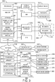
- Fig. 3 is a block diagram of a computing system 300 that includes separate units, which may be used to control the motion of a robot in the presence of a moving object according to embodiments described herein.
- the computing system 300 may include a processor 302, e.g., a central processing unit (CPU), that is adapted to execute stored instructions, as well as a memory device 304 that stores instructions that are executable by the processor 302. Such instructions may be used to detect MCOs in a workspace occupied by a robot, and control the motion of the robot.
- the processor 302 can be a single core processor, multi-core processor, computing cluster, or any number of other configurations.
- the memory device 304 can include random access memory (RAM), read only memory (ROM), flash memory, or any other suitable memory systems.
- the processor 302 may be connected through a bus 306 to a storage device 308 adapted to store a frame capture and analysis module 310, a moving connected object module 312, and a location alert module 314.
- the storage device 308 may be a hard drive, an optical drive, a thumb drive, an array of drives, or any combinations thereof.
- a network interface controller 315 may be adapted to connect the processor 302 through the bus 306 to a network 316. Through the network 316, control signals may be sent to a robot controller 318 for slowing or stopping motion when unexpected MCOs are present, and for restarting motion when the area around the robot is clear of unexpected MCOs.
- the processor 302 may be linked through the bus 306 to a display interface 320 adapted to connect the system 300 to a display device 322.
- the display device 322 can include a computer monitor, camera, television, projector, virtual reality display, three-dimensional (3D) display, or mobile device, among others.
- a human machine interface 324 within the computing system 300 may connect the processor 302 to a keyboard 326 and a pointing device 328.
- the pointing device 328 can include a mouse, trackball, touchpad, joy stick, pointing stick, stylus, or touchscreen, among others.
- the processor 302 may also be linked through the bus 306 to an input/output interface 330 adapted to connect the computing system 300 to any number of additional input/output devices.
- the input/output interface 330 may connect the computing system 300 to an IR camera 332 and one or more IR lasers 334.
- the IR camera 332 and IR lasers 334 may be included within a single imaging device 336.
- the imaging device 336 may be a 3D camera, gaming system, RGB-D camera, computer, or the like. Further, the imaging device 336 does not need to be based on IR lasers and the like, but may include stereoscopic technologies.
- all or a portion of the IR lasers 334 may be externally connected to an imaging device including the IR camera 332.
- the computing system 300 may be an imaging device.
- the IR camera 332 and the IR lasers 334 may reside within the computing system 300, rather than being externally connected to the computing system 300 via the input/output interface 330.
- the computing system 300 may include a graphics processing unit (GPU) 338.
- the GPU 338 may be linked through the bus 306 to the processor 302, the memory device 304, the storage device 308, the input/output interface 330, and any number of other components of the computing system 300.
- the GPU 338 is adapted to execute instructions, such as the instructions stored in the memory device 304, either in conjunction with or independently of the processor 302.
- the GPU 338 may execute all or a portion of the instructions that are used to implement the method for analyzing frame data to determine the presence of MCOs in a series of frames.
- the processor 302 and the GPU 338 may be used in parallel for the reconstruction of frame data in captured images.
- the frame data may be reconstructed at a rate of at least about 20 frames per second (fps), providing a fast action for the control of the motion of the robot.
- fps frames per second
- Higher or lower frame reconstruction rates can be achieved, depending on the processor 302 and GPU 338 used.
- Higher reconstruction rates such as 30 fps, 40 fps, or higher, may be useful when a robot is interacting with an unexpected MCO, for example, removing parts from an automated cart.
- Lower reconstruction rates, such as 20 fps, 10 fps, or lower, may provide adequate coverage at a lower cost, for example, in systems used to slow or stop a robot based on a location of an unexpected MCO.
- the computing system 300 may be coupled to a warning system 340, which may include visible warning systems 342, such as flashing lights, and audible alert systems 344, such as sirens or klaxons. It can be understood that the warning system 340 may be directly coupled to the computing system 300, for example, through the input/output interface 330.
- the robot controller 318 may include a network interface card 346 for communications with the computing system 300 over the network 316.
- the robot controller 318 may also include similar units to the computing system 300.
- the robot controller 318 may include a processor 348, e.g., a central processing unit (CPU), that is adapted to execute stored instructions, as well as a memory device 350 that stores instructions that are executable by the processor 348.
- Such instructions may be include the operational code for the robot, such as code to control the motion of the robot.
- the processor 348 can be a single core processor, multi-core processor, computing cluster, or any number of other configurations.
- the processor 348 may be part of a microcontroller, a distributed control system (DCS), a programmable logic controller (PLC), or other types of plant control systems.
- the memory device 350 can include random access memory (RAM), read only memory (ROM), flash memory, or any other suitable memory systems.
- the processor 348 may be connected through a bus 352 to a storage device 354 adapted to store a motion control module 356, a sensor or position detection module 358, and an operations module 360, for example, including the robots specific operational program.
- the storage device 354 can include a hard drive, an optical drive, a thumb drive, an array of drives, or any combinations thereof.
- the network interface controller 346 may be adapted to connect the processor 348 through the bus 352 to the network 316. Through the network 316, control signals may be sent to the robot controller 318 for slowing or stopping motion when unexpected MCOs are present, and for restarting motion when the area around the robot is clear of unexpected MCOs.
- the processor 348 may be linked through the bus 352 to a display interface 362 adapted to connect the robot controller 318 to a display device 364.
- the display device 364 can include an LCD screen, a computer monitor, or a mobile device, among others.
- a human machine interface 366 within the robot controller 318 may connect the processor 348 to a keyboard 368, a pointing device 370, or a training pendant 372.
- the pointing device 370 can include a mouse, trackball, touchpad, joy stick, pointing stick, stylus, or touchscreen, among others.
- the training pendant 372 can be used to enter the operational program into the operations module 360, by training the movement of the robot. During training, the vision module may be disabled to allow the training to be performed.
- the processor 348 may also be linked through the bus 352 to a motor controller 374 adapted to connect the robot controller 318 to any number of motors 376 to control the motion of the robot.
- the motor controller 374 may control motors for a robot arm, allowing the robot arm to rotate vertically on a base, extend out from the base, open and close grippers, or other effectors, and the like.
- the processor 348 may also be linked through the bus 352 to a position sensor interface 378.
- the position sensor interface 378 may link the robot controller 318 to a number of position sensors 380 that may let the robot controller 318 know the current position of the robot.
- a robot arm may include optical sensors at each joint to let the robot controller 318 know the position of the robot arm at that joint.
- Fig. 3 The block diagram of Fig. 3 is not intended to indicate that the computing system 300 is to include all the components shown in Fig. 3 . Further, the computing system 300 may include any number of additional components not shown in Fig. 3 , depending on the details of the specific implementation. For example, controllers for auxiliary equipment, as described above, may be coupled to the network, and in communication with the computing system 300 and the robot controller 318. As mentioned, the system is not limited to two units, but may have the functionality in a single apparatus.
- Fig. 4 is a block diagram of a robot 400 that includes a visual system for controlling motion in the presence of a moving object. Like numbered items are as described above.
- the robot controller 402 is directly coupled to a depth sensor 210 for detection of unexpected MCOs in a workspace. As discussed with respect to Fig. 5 , this combines the functionality of the two separate units into a single robot controller 402.
- the human machine interface devices (HMI) 404 can include a display, pointing device, keyboard, or training pendant, as described above.
- the robot controller 402 may also interact with line controls 406, which may control auxiliary equipment, such as conveyor belts, and the like.
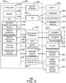
- Fig. 5 is a block diagram of a robot 500 that may be used in the presence of a moving object according to embodiments described herein. Like numbered items are as described above. In this embodiment, all of the functionality of the two unit system, described with respect to Fig. 3 , has been incorporated into the robot control 502. Further, an alert system controller 504 may be used to control the warning devices 342 and 344.
- Fig. 6 is a process flow diagram of a method 600 for controlling a robot in the presence of a moving object.
- the method 600 starts at block 602 with the capturing of a frame, or image, of the workspace. This may be performed using a depth camera (RGB-D) or a stereoscopic camera, as described above.
- the frame data is analyzed to identify connected objects. This may be performed as described with respect to Fig. 1 .
- the frame data is compared to a previous frame to identify motion. Any connected object showing motion can be identified as a moving connected object (MCO). A total count of MCOs is made for objects within the boundaries of the workspace.
- MCO moving connected object
- data from the robot controller can be used to determine if motion is expected for the robot, auxiliary equipment, or both. If motion is expected, at block 610, every MCO for which motion is expected can be removed from the count.
- Process flow proceeds to block 612 to determine if an unexpected MCO is present, e.g., if the count of MCOs remains at one or greater after all expected MCOs have been removed. If not, process flow returns to block 602 to continue.
- process flow may proceeds to block 614 to locate the unexpected MCO, for example, in a hazardous region (H), a warning region (W).
- H hazardous region
- W warning region
- block 612 may be eliminated and process flow may go directly to block 616.
- process flow may proceed to block 616.
- audible warnings, visual warnings, or both are activated.
- the motion of the robot is stopped.
- Process flow then resumes at block 602. It can be noted that when the unexpected MCO count returns to zero, the alerts may be stopped and motion restarted automatically. In some embodiments, the motion can continue to be halted until an operator allows motion to resume.
- process flow proceeds to block 620.
- audible warnings, visual warnings, or both are activated.
- the motion of the robot is slowed. Process flow then resumes at block 602. It can be noted that when the unexpected MCO count returns to zero, the alerts may be stopped and the robot may be allowed to return to full speed automatically.
- the method 600 is not limited to the blocks shown.
- blocks may be added to control auxiliary equipment, based, at least in part, on the detection of unexpected MCOs.
- the motion of the robot may include other actions, such as moving the robot proximate to an unexpected MCO at a slow speed to allow interaction between the unexpected MCO and the robot. Further, as mentioned above, not all blocks have to be present.
- Block 614 may be eliminated if there is only one zone used.
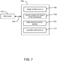
- Fig. 7 is a block diagram of a computer-readable storage medium 700 that stores code adapted to control a robot in the presence of a moving object.
- the code is accessible by a processor 702 over a bus 704.
- the computer-readable storage medium may include hard drives, thumb-drives, ram-drives, or any number of other units, as described with respect to Fig. 2 .
- the code may include, for example, a frame-capture module 706 configures to capture a frame from a depth sensing camera.
- a moving connected object module 708 may be used to analyze a current frame and compare the results to results for a past frame to identify MCOs in the frames.
- a robot motion control module 710 may be used to keep track of the number of unexpected MCOs in the workspace, for example, based on data from the moving connected object module 708 and a robot controller.
- a location alert module 712 can then be used to instruct a robot to slow or stop motion.
Applications Claiming Priority (3)
| Application Number | Priority Date | Filing Date | Title |
|---|---|---|---|
| US14/172,230 US9452531B2 (en) | 2014-02-04 | 2014-02-04 | Controlling a robot in the presence of a moving object |
| EP15703701.1A EP3102367B1 (fr) | 2014-02-04 | 2015-01-30 | Commande d'un robot en présence d'un objet mobile |
| PCT/US2015/013633 WO2015119838A2 (fr) | 2014-02-04 | 2015-01-30 | Commande d'un robot en présence d'un objet mobile |
Related Parent Applications (2)
| Application Number | Title | Priority Date | Filing Date |
|---|---|---|---|
| EP15703701.1A Division-Into EP3102367B1 (fr) | 2014-02-04 | 2015-01-30 | Commande d'un robot en présence d'un objet mobile |
| EP15703701.1A Division EP3102367B1 (fr) | 2014-02-04 | 2015-01-30 | Commande d'un robot en présence d'un objet mobile |
Publications (2)
| Publication Number | Publication Date |
|---|---|
| EP3715065A1 true EP3715065A1 (fr) | 2020-09-30 |
| EP3715065B1 EP3715065B1 (fr) | 2022-01-26 |
Family
ID=52464606
Family Applications (2)
| Application Number | Title | Priority Date | Filing Date |
|---|---|---|---|
| EP15703701.1A Active EP3102367B1 (fr) | 2014-02-04 | 2015-01-30 | Commande d'un robot en présence d'un objet mobile |
| EP20169088.0A Active EP3715065B1 (fr) | 2014-02-04 | 2015-01-30 | Commande d'un robot en présence d'un objet mobile |
Family Applications Before (1)
| Application Number | Title | Priority Date | Filing Date |
|---|---|---|---|
| EP15703701.1A Active EP3102367B1 (fr) | 2014-02-04 | 2015-01-30 | Commande d'un robot en présence d'un objet mobile |
Country Status (5)
| Country | Link |
|---|---|
| US (3) | US9452531B2 (fr) |
| EP (2) | EP3102367B1 (fr) |
| KR (1) | KR102293263B1 (fr) |
| CN (1) | CN106471546A (fr) |
| WO (1) | WO2015119838A2 (fr) |
Cited By (1)
| Publication number | Priority date | Publication date | Assignee | Title |
|---|---|---|---|---|
| EP4131139A1 (fr) * | 2021-08-03 | 2023-02-08 | Sick Ag | Dispositif capteur et procédé de sécurisation d'une zone de surveillance |
Families Citing this family (93)
| Publication number | Priority date | Publication date | Assignee | Title |
|---|---|---|---|---|
| US9452531B2 (en) * | 2014-02-04 | 2016-09-27 | Microsoft Technology Licensing, Llc | Controlling a robot in the presence of a moving object |
| US9701018B2 (en) * | 2014-04-01 | 2017-07-11 | Bot & Dolly, Llc | Software interface for authoring robotic manufacturing process |
| US10462076B2 (en) | 2014-05-06 | 2019-10-29 | Clearpath Robotics Inc. | System, apparatus and method for automatic environmental data collection and analysis |
| AT516097B1 (de) * | 2014-07-03 | 2016-09-15 | Blue Danube Robotics Gmbh | Schutzverfahren und Schutzvorrichtung für Handhabungsgerät |
| US9902061B1 (en) * | 2014-08-25 | 2018-02-27 | X Development Llc | Robot to human feedback |
| DE102014223701B4 (de) * | 2014-11-20 | 2019-03-07 | Siemens Healthcare Gmbh | Vorgebbare Beweglichkeit für ein robotisches Gerät |
| US9623560B1 (en) * | 2014-11-26 | 2017-04-18 | Daniel Theobald | Methods of operating a mechanism and systems related therewith |
| JP6530621B2 (ja) * | 2015-03-17 | 2019-06-12 | ファナック株式会社 | 機械と可搬式無線操作盤との間の距離に基づいて警告を発生し、または機械を停止させる機能を備えたロボット制御システム |
| US10241515B2 (en) | 2015-05-29 | 2019-03-26 | Clearpath Robotics, Inc. | Method, system and apparatus for handling operational constraints for control of unmanned vehicles |
| JP6464945B2 (ja) * | 2015-07-03 | 2019-02-06 | 株式会社デンソーウェーブ | ロボットシステム |
| JP6554945B2 (ja) * | 2015-07-03 | 2019-08-07 | 株式会社デンソーウェーブ | ロボットシステム |
| JP6554946B2 (ja) * | 2015-07-03 | 2019-08-07 | 株式会社デンソーウェーブ | ロボットシステム |
| DE102015009048B3 (de) * | 2015-07-13 | 2016-08-18 | Kuka Roboter Gmbh | Steuern eines nachgiebig geregelten Roboters |
| US10198706B2 (en) * | 2015-07-31 | 2019-02-05 | Locus Robotics Corp. | Operator identification and performance tracking |
| US20170092000A1 (en) * | 2015-09-25 | 2017-03-30 | Moshe Schwimmer | Method and system for positioning a virtual object in a virtual simulation environment |
| US20170091999A1 (en) * | 2015-09-25 | 2017-03-30 | Rafael Blumenfeld | Method and system for determining a configuration of a virtual robot in a virtual environment |
| US10215852B1 (en) * | 2015-10-05 | 2019-02-26 | Google Llc | Robotic radar assistance |
| JP6601155B2 (ja) * | 2015-10-28 | 2019-11-06 | 株式会社デンソーウェーブ | ロボット制御システム |
| JP6328599B2 (ja) * | 2015-11-20 | 2018-05-23 | ファナック株式会社 | ロボットの動作可能範囲を算出するロボットの手動送り装置 |
| DE102015225587A1 (de) * | 2015-12-17 | 2017-06-22 | Volkswagen Aktiengesellschaft | Interaktionssystem und Verfahren zur Interaktion zwischen einer Person und mindestens einer Robotereinheit |
| US10662045B2 (en) | 2016-02-11 | 2020-05-26 | Clearpath Robotics Inc. | Control augmentation apparatus and method for automated guided vehicles |
| AT518498B1 (de) * | 2016-03-29 | 2018-09-15 | B & R Ind Automation Gmbh | Positionsüberwachung einer Kinematik |
| DE102016004889A1 (de) * | 2016-04-22 | 2017-10-26 | Kuka Roboter Gmbh | Zufuhr von elektrischer Energie und/oder Kraftstoff zu einem Kraftfahrzeug mittels eines Roboters |
| DE102016004902A1 (de) * | 2016-04-22 | 2017-10-26 | Kuka Roboter Gmbh | Überwachung eines Roboters |
| WO2017185207A1 (fr) * | 2016-04-25 | 2017-11-02 | 深圳普得技术有限公司 | Robot social et son procédé de détection |
| US20170330413A1 (en) * | 2016-05-13 | 2017-11-16 | Universal Entertainment Corporation | Speech recognition device and gaming machine |
| US9868214B2 (en) * | 2016-06-20 | 2018-01-16 | X Development Llc | Localization of a mobile system |
| JP6470235B2 (ja) * | 2016-07-27 | 2019-02-13 | ファナック株式会社 | 安全管理方法および安全管理システム |
| CN107717982B (zh) * | 2016-08-12 | 2020-09-25 | 财团法人工业技术研究院 | 机械手臂的控制装置及操作方法 |
| US11000953B2 (en) * | 2016-08-17 | 2021-05-11 | Locus Robotics Corp. | Robot gamification for improvement of operator performance |
| US10414048B2 (en) | 2016-09-14 | 2019-09-17 | Faro Technologies, Inc. | Noncontact safety sensor and method of operation |
| CN106406312B (zh) * | 2016-10-14 | 2017-12-26 | 平安科技(深圳)有限公司 | 导览机器人及其移动区域标定方法 |
| US11124392B2 (en) | 2016-11-22 | 2021-09-21 | Manitowoc Crane Companies, Llc | Optical detection and analysis for boom angles on a crane |
| GB2559020B (en) * | 2016-11-28 | 2021-11-03 | Faro Tech Inc | Noncontact safety sensor and method of operation |
| JP6420296B2 (ja) * | 2016-12-01 | 2018-11-07 | ファナック株式会社 | ロボットの干渉領域を自動で設定するロボット制御装置 |
| KR20180076450A (ko) * | 2016-12-28 | 2018-07-06 | 한국기계연구원 | 로봇의 충돌 방지 장치 및 방법 |
| US20230191635A1 (en) * | 2017-01-13 | 2023-06-22 | Clara Vu | Dynamic, interactive signaling of safety-related conditions in a monitored environment |
| US11518051B2 (en) | 2017-02-07 | 2022-12-06 | Veo Robotics, Inc. | Dynamic, interactive signaling of safety-related conditions in a monitored environment |
| WO2018148181A1 (fr) * | 2017-02-07 | 2018-08-16 | Veo Robotics, Inc. | Surveillance de sécurité d'espace de travail et commande d'équipement |
| US11945119B2 (en) | 2017-02-07 | 2024-04-02 | Veo Robotics, Inc. | Crosstalk mitigation for multi-cell workspace monitoring |
| US11541543B2 (en) | 2017-02-07 | 2023-01-03 | Veo Robotics, Inc. | Dynamic, interactive signaling of safety-related conditions in a monitored environment |
| US11097422B2 (en) | 2017-02-07 | 2021-08-24 | Veo Robotics, Inc. | Safety-rated multi-cell workspace mapping and monitoring |
| US11820025B2 (en) | 2017-02-07 | 2023-11-21 | Veo Robotics, Inc. | Safe motion planning for machinery operation |
| US11679504B2 (en) | 2018-02-06 | 2023-06-20 | Veo Robotics, Inc. | Crosstalk mitigation for multi-cell workspace monitoring |
| JP6866673B2 (ja) * | 2017-02-15 | 2021-04-28 | オムロン株式会社 | 監視システム、監視装置、および監視方法 |
| JP6490121B2 (ja) * | 2017-02-17 | 2019-03-27 | ファナック株式会社 | ロボットシステム |
| JP6900918B2 (ja) * | 2017-03-14 | 2021-07-07 | オムロン株式会社 | 学習装置及び学習方法 |
| WO2018168536A1 (fr) * | 2017-03-14 | 2018-09-20 | Omron Corporation | Appareil d'apprentissage et procédé d'apprentissage |
| DK201700203A1 (en) * | 2017-03-23 | 2018-11-27 | Mrr | Safety system for collaborative robot |
| US10766140B2 (en) * | 2017-04-13 | 2020-09-08 | Battelle Memorial Institute | Teach mode collision avoidance system and method for industrial robotic manipulators |
| JP6953778B2 (ja) * | 2017-04-28 | 2021-10-27 | オムロン株式会社 | 協調ロボット、コントローラ、および方法 |
| JP6416980B1 (ja) * | 2017-05-17 | 2018-10-31 | ファナック株式会社 | 監視領域を分割した空間領域を監視する監視装置 |
| WO2018213931A1 (fr) | 2017-05-25 | 2018-11-29 | Clearpath Robotics Inc. | Systèmes et procédés d'orientation de processus au moyen d'un bras robotisé |
| CN107363831B (zh) * | 2017-06-08 | 2020-01-10 | 中国科学院自动化研究所 | 基于视觉的遥操作机器人控制系统及方法 |
| DE102017005604A1 (de) * | 2017-06-12 | 2018-12-13 | Kuka Deutschland Gmbh | Überwachung eines Roboters |
| EP3432099B1 (fr) | 2017-07-20 | 2021-09-01 | Siemens Aktiengesellschaft | Procédé et système de détection d'un état anormal d'une machine |
| US11001446B2 (en) | 2017-08-31 | 2021-05-11 | Clearpath Robotics Inc. | Apparatus, systems, and methods for payload pick-up and drop-off with a self-driving material-transport vehicle |
| WO2019041043A1 (fr) | 2017-08-31 | 2019-03-07 | Clearpath Robotics Inc. | Systèmes et procédés pour générer une mission pour un véhicule de transport de matériau à conduite autonome |
| US11072071B2 (en) * | 2017-09-19 | 2021-07-27 | Autodesk, Inc. | Modifying robot dynamics in response to human presence |
| JP6633584B2 (ja) * | 2017-10-02 | 2020-01-22 | ファナック株式会社 | ロボットシステム |
| US10564823B1 (en) | 2017-10-03 | 2020-02-18 | Sprint Communications Company L.P. | Mobile device transparent screen overlay |
| WO2019084686A1 (fr) * | 2017-10-31 | 2019-05-09 | Clearpath Robotics Inc. | Systèmes et procédés permettant de faire fonctionner un équipement robotique dans des zones contrôlées |
| EP3495202B1 (fr) * | 2017-12-05 | 2020-08-19 | Guima Palfinger S.A.S. | Système de détection montable sur camion |
| ES1222444Y (es) * | 2017-12-06 | 2019-03-22 | Wide Automation S R L | Sistema de seguridad |
| US20210205995A1 (en) * | 2018-02-06 | 2021-07-08 | Clara Vu | Robot end-effector sensing and identification |
| US20220088787A1 (en) * | 2018-02-06 | 2022-03-24 | Clara Vu | Workplace monitoring and semantic entity identification for safe machine operation |
| US11830131B2 (en) | 2018-02-06 | 2023-11-28 | Veo Robotics, Inc. | Workpiece sensing for process management and orchestration |
| TWI664573B (zh) | 2018-05-11 | 2019-07-01 | 國立交通大學 | 動作計算裝置、機器人系統及機器人控制方法 |
| CN108789500B (zh) * | 2018-05-24 | 2021-11-05 | 上海节卡机器人科技有限公司 | 人机安全防护系统及安全防护方法 |
| EP3578320B1 (fr) | 2018-06-07 | 2021-09-15 | Sick Ag | Configurer un endroit dangereux surveillé par un capteur tridimensionnel |
| JP7398658B2 (ja) * | 2018-06-11 | 2023-12-15 | パナソニックIpマネジメント株式会社 | 測距システム及び測距方法 |
| DE102018114156B3 (de) * | 2018-06-13 | 2019-11-14 | Volkswagen Aktiengesellschaft | Verfahren zur Steuerung eines Roboters, insbesondere eines Industrieroboters, sowie Vorrichtung zur Steuerung des Roboters |
| JP7155660B2 (ja) * | 2018-06-26 | 2022-10-19 | セイコーエプソン株式会社 | ロボット制御装置およびロボットシステム |
| CN108858193B (zh) * | 2018-07-06 | 2020-07-03 | 清华大学深圳研究生院 | 一种机械臂抓取方法及系统 |
| JP7107091B2 (ja) * | 2018-08-22 | 2022-07-27 | セイコーエプソン株式会社 | ロボットシステム及び制御装置 |
| CN112640447B (zh) | 2018-08-30 | 2022-04-29 | 韦奥机器人股份有限公司 | 深度感测计算机视觉系统 |
| JP7299642B2 (ja) | 2018-08-30 | 2023-06-28 | ヴェオ ロボティクス, インコーポレイテッド | 自動的センサ位置合わせおよび構成のためのシステムおよび方法 |
| JP7262847B2 (ja) | 2018-08-30 | 2023-04-24 | ヴェオ ロボティクス, インコーポレイテッド | 安全重視用途に関する産業ロボット動力学のシステム識別 |
| CN109514322A (zh) * | 2018-11-02 | 2019-03-26 | 拓卡奔马机电科技有限公司 | 裁床安全防护系统及方法 |
| US11969898B2 (en) * | 2018-12-17 | 2024-04-30 | Datalogic Ip Tech S.R.L. | Multi-sensor optimization of automatic machines to prevent safety issues |
| DE102018133472B3 (de) * | 2018-12-21 | 2020-03-12 | Franka Emika Gmbh | Bewegungsüberwachung eines Robotermanipulators |
| JP7378168B2 (ja) | 2019-02-27 | 2023-11-13 | ヴェオ ロボティクス, インコーポレイテッド | 安全用途のためのシステムアーキテクチャ |
| CN109794940A (zh) * | 2019-03-01 | 2019-05-24 | 北京达盛智联教育技术有限公司 | 一种双目人工智能机械臂教学装置 |
| CN109732560A (zh) * | 2019-03-14 | 2019-05-10 | 北京物资学院 | 一种喷绘机器人 |
| EP3941693A4 (fr) * | 2019-03-20 | 2022-11-30 | Covidien LP | Systèmes de détection de collision chirurgicale robotique |
| GB2583485B (en) * | 2019-04-29 | 2021-09-01 | Arrival Ltd | A system for preventing collisions in a robotic cell environment |
| CN110026718B (zh) * | 2019-05-21 | 2021-04-02 | 郑万众 | 一种具有预警功能的智能焊接机器人手臂 |
| US20230001587A1 (en) * | 2019-12-05 | 2023-01-05 | Alexander Zak | Method and setup for fenceless robotics |
| US11669988B1 (en) * | 2020-02-10 | 2023-06-06 | 4DMobile, LLC | System and method for three-dimensional box segmentation and measurement |
| CN112060058B (zh) * | 2020-09-08 | 2022-02-01 | 广州云弈科技有限公司 | 一种用于区块链智能机器人的防护底座 |
| US20230302650A1 (en) * | 2020-10-15 | 2023-09-28 | Intuitive Surgical Operations, Inc. | Detection and mitigation of predicted collisions of objects with user control system |
| JP2022175508A (ja) * | 2021-05-13 | 2022-11-25 | オムロン株式会社 | 領域設定装置、ラック、制御システム、領域設定方法及びプログラム |
| KR20230057649A (ko) * | 2021-10-22 | 2023-05-02 | 주식회사 한화 | 로봇 안전 감시 시스템 |
Citations (5)
| Publication number | Priority date | Publication date | Assignee | Title |
|---|---|---|---|---|
| US20060049939A1 (en) * | 2004-09-08 | 2006-03-09 | Sick Ag | Method and apparatus for the control of a safety-relevant function of a machine |
| US20090237499A1 (en) * | 2006-08-02 | 2009-09-24 | Ulrich Kressel | Method for observation of a person in an industrial environment |
| WO2010063319A1 (fr) * | 2008-12-03 | 2010-06-10 | Abb Research Ltd. | Système de sécurité de robot et procédé associé |
| US20120327190A1 (en) * | 2010-02-23 | 2012-12-27 | Ifm Electronic Gmbh | Monitoring system |
| US20140022161A1 (en) * | 2009-10-07 | 2014-01-23 | Microsoft Corporation | Human tracking system |
Family Cites Families (20)
| Publication number | Priority date | Publication date | Assignee | Title |
|---|---|---|---|---|
| US5347459A (en) * | 1993-03-17 | 1994-09-13 | National Research Council Of Canada | Real time collision detection |
| US5548694A (en) * | 1995-01-31 | 1996-08-20 | Mitsubishi Electric Information Technology Center America, Inc. | Collision avoidance system for voxel-based object representation |
| AU2003239171A1 (en) | 2002-01-31 | 2003-09-02 | Braintech Canada, Inc. | Method and apparatus for single camera 3d vision guided robotics |
| EP1578290B1 (fr) * | 2002-12-06 | 2012-03-28 | Koninklijke Philips Electronics N.V. | Appareil et procede pour le positionnement automatise d'un dispositif |
| US7315738B1 (en) | 2003-09-11 | 2008-01-01 | Sprint Spectrum L.P. | Method and system for managing multiple directory numbers for a mobile station |
| DE102004041821A1 (de) * | 2004-08-27 | 2006-03-16 | Abb Research Ltd. | Vorrichtung und Verfahren zur Sicherung eines maschinell gesteuerten Handhabungsgerätes |
| CN100556623C (zh) * | 2004-10-19 | 2009-11-04 | 松下电器产业株式会社 | 自动机械装置 |
| DE502006009264D1 (de) * | 2006-09-30 | 2011-05-19 | Abb Technology Ag | Verfahren und System zur Auslegung und Überprüfung von Sicherheitsbereichen eines Roboters |
| DE102007013299A1 (de) | 2007-03-06 | 2008-09-11 | Cedes Ag | Sensorvorrichtung sowie Anlage mit einem Förderer und einer Sensorvorrichtung |
| US8315738B2 (en) * | 2008-05-21 | 2012-11-20 | Fanuc Robotics America, Inc. | Multi-arm robot system interference check via three dimensional automatic zones |
| US7790920B2 (en) | 2008-09-11 | 2010-09-07 | Lyondell Chemical Technology, L.P. | Preparation of acetic acid |
| KR101572851B1 (ko) | 2008-12-22 | 2015-11-30 | 삼성전자 주식회사 | 동적 환경에서 모바일 플랫폼의 지도 작성방법 |
| JP4648486B2 (ja) * | 2009-01-26 | 2011-03-09 | ファナック株式会社 | 人間とロボットとの協調動作領域を有する生産システム |
| US8415609B2 (en) * | 2009-01-31 | 2013-04-09 | Keyence Corporation | Safety photoelectric switch |
| JP2013509902A (ja) | 2009-11-04 | 2013-03-21 | コーニンクレッカ フィリップス エレクトロニクス エヌ ヴィ | 距離センサを使用した衝突の回避と探知 |
| KR101151707B1 (ko) * | 2009-12-30 | 2012-06-15 | 한국기술교육대학교 산학협력단 | Cts를 이용한 물체감지 및 이동로봇 시스템 |
| WO2011084160A1 (fr) * | 2010-01-08 | 2011-07-14 | Otis Elevator Company | Entrée de destination sans fil pour un système d'envoi d'ascenseur |
| DE102010063208A1 (de) * | 2010-12-16 | 2012-06-21 | Robert Bosch Gmbh | Verfahren zum Betreiben einer Sicherungseinrichtung für eine Handhabungsvorrichtung, Sicherungseinrichtung für eine Handhabungsvorrichtung und Handhabungsvorrichtung |
| US9043025B2 (en) * | 2012-08-31 | 2015-05-26 | Rethink Robotics, Inc. | Systems and methods for safe robot operation |
| US9452531B2 (en) * | 2014-02-04 | 2016-09-27 | Microsoft Technology Licensing, Llc | Controlling a robot in the presence of a moving object |
-
2014
- 2014-02-04 US US14/172,230 patent/US9452531B2/en active Active
-
2015
- 2015-01-30 KR KR1020167024215A patent/KR102293263B1/ko active IP Right Grant
- 2015-01-30 EP EP15703701.1A patent/EP3102367B1/fr active Active
- 2015-01-30 EP EP20169088.0A patent/EP3715065B1/fr active Active
- 2015-01-30 CN CN201580007104.8A patent/CN106471546A/zh active Pending
- 2015-01-30 WO PCT/US2015/013633 patent/WO2015119838A2/fr active Application Filing
-
2016
- 2016-07-29 US US15/224,109 patent/US10195741B2/en active Active
-
2018
- 2018-12-20 US US16/226,984 patent/US10994419B2/en active Active
Patent Citations (5)
| Publication number | Priority date | Publication date | Assignee | Title |
|---|---|---|---|---|
| US20060049939A1 (en) * | 2004-09-08 | 2006-03-09 | Sick Ag | Method and apparatus for the control of a safety-relevant function of a machine |
| US20090237499A1 (en) * | 2006-08-02 | 2009-09-24 | Ulrich Kressel | Method for observation of a person in an industrial environment |
| WO2010063319A1 (fr) * | 2008-12-03 | 2010-06-10 | Abb Research Ltd. | Système de sécurité de robot et procédé associé |
| US20140022161A1 (en) * | 2009-10-07 | 2014-01-23 | Microsoft Corporation | Human tracking system |
| US20120327190A1 (en) * | 2010-02-23 | 2012-12-27 | Ifm Electronic Gmbh | Monitoring system |
Non-Patent Citations (3)
| Title |
|---|
| FABRIZIO FLACCO ET AL: "Depth space approach to human-robot collision avoidance", ROBOTICS AND AUTOMATION (ICRA), 2012 IEEE INTERNATIONAL CONFERENCE ON, IEEE, 14 May 2012 (2012-05-14), pages 338 - 345, XP032450976, ISBN: 978-1-4673-1403-9, DOI: 10.1109/ICRA.2012.6225245 * |
| IVANA MIKIC: "Human Body Model Acquisition and Tracking Using Voxel Data", INTERNATIONAL JOURNAL OF COMPUTER VISION 53(3), 1 January 2003 (2003-01-01), pages 199 - 223, XP055065208, Retrieved from the Internet <URL:http://homes.di.unimi.it/borghese/Teaching/IntelligentSystems/Old/IntelligentSystems_2004_2005/Documents/Vision/03_HumanBody_Tracking_MikicTrivediHunter.pdf> [retrieved on 20130604] * |
| PAUL RYBSKI ET AL: "Sensor fusion for human safety in industrial workcells", INTELLIGENT ROBOTS AND SYSTEMS (IROS), 2012 IEEE/RSJ INTERNATIONAL CONFERENCE ON, IEEE, 7 October 2012 (2012-10-07), pages 3612 - 3619, XP032287880, ISBN: 978-1-4673-1737-5, DOI: 10.1109/IROS.2012.6386034 * |
Cited By (1)
| Publication number | Priority date | Publication date | Assignee | Title |
|---|---|---|---|---|
| EP4131139A1 (fr) * | 2021-08-03 | 2023-02-08 | Sick Ag | Dispositif capteur et procédé de sécurisation d'une zone de surveillance |
Also Published As
| Publication number | Publication date |
|---|---|
| KR20160117559A (ko) | 2016-10-10 |
| US10195741B2 (en) | 2019-02-05 |
| WO2015119838A3 (fr) | 2016-06-16 |
| EP3102367A2 (fr) | 2016-12-14 |
| EP3102367B1 (fr) | 2020-05-13 |
| WO2015119838A2 (fr) | 2015-08-13 |
| KR102293263B1 (ko) | 2021-08-23 |
| US20150217455A1 (en) | 2015-08-06 |
| US10994419B2 (en) | 2021-05-04 |
| CN106471546A (zh) | 2017-03-01 |
| US20190118381A1 (en) | 2019-04-25 |
| US9452531B2 (en) | 2016-09-27 |
| EP3715065B1 (fr) | 2022-01-26 |
| US20160354927A1 (en) | 2016-12-08 |
Similar Documents
| Publication | Publication Date | Title |
|---|---|---|
| US10994419B2 (en) | Controlling a robot in the presence of a moving object | |
| US10611023B2 (en) | Systems and methods for performing occlusion detection | |
| US9864913B2 (en) | Device and method for safeguarding an automatically operating machine | |
| CN106537186B (zh) | 用于使用机器视觉系统执行同时定位和映射的系统和方法 | |
| JP5283622B2 (ja) | 機械の衝突防止のためのカメラを利用した監視方法及び装置 | |
| JP2019519387A (ja) | 拡張現実ロボットシステムの可視化 | |
| US20190314998A1 (en) | Teaching apparatus and teaching method for robots | |
| US20200254610A1 (en) | Industrial robot system and method for controlling an industrial robot | |
| CN107479500B (zh) | 一种带视觉装置的加工中心运动定位数控系统及方法 | |
| WO2018068446A1 (fr) | Procédé et dispositif de suivi, et support de stockage informatique | |
| CN112066994A (zh) | 一种消防机器人局部自主导航方法及系统 | |
| Zainuddin et al. | Autonomous navigation of mobile robot using Kinect sensor | |
| Sugimoto et al. | Half-diminished reality image using three rgb-d sensors for remote control robots | |
| Fetzner et al. | A 3D representation of obstacles in the robots reachable area considering occlusions | |
| WO2020195267A1 (fr) | Système de commande, procédé de commande et unité de commande | |
| Schmidt | Real-time collision detection and collision avoidance | |
| RU2685996C1 (ru) | Способ и система предиктивного избегания столкновения манипулятора с человеком | |
| KR101566964B1 (ko) | 이동 물체를 추적할 수 있는 어라운드 뷰 모니터링 방법, 이를 수행하는 어라운드 뷰 모니터링 장치 및 이를 저장하는 기록매체 | |
| Kidiraliev et al. | Using optical sensors for industrial robot-human interactions in a Gazebo environment | |
| CN113226666A (zh) | 用于监控机器人系统的方法和装置 | |
| Wang et al. | Safety in human-robot collaborative assembly | |
| CN114074320A (zh) | 机器人控制方法及装置 | |
| JP2022096933A (ja) | ロボットシステムの報知方法およびロボットシステム | |
| Karungaru et al. | A Simple Interface for Mobile Robot Equipped with Single Camera using Motion Stereo Vision | |
| CN113727277A (zh) | 三维动态电子栅栏系统及监控方法 |
Legal Events
| Date | Code | Title | Description |
|---|---|---|---|
| PUAI | Public reference made under article 153(3) epc to a published international application that has entered the european phase |
Free format text: ORIGINAL CODE: 0009012 |
|
| STAA | Information on the status of an ep patent application or granted ep patent |
Free format text: STATUS: REQUEST FOR EXAMINATION WAS MADE |
|
| 17P | Request for examination filed |
Effective date: 20200409 |
|
| AC | Divisional application: reference to earlier application |
Ref document number: 3102367 Country of ref document: EP Kind code of ref document: P |
|
| AK | Designated contracting states |
Kind code of ref document: A1 Designated state(s): AL AT BE BG CH CY CZ DE DK EE ES FI FR GB GR HR HU IE IS IT LI LT LU LV MC MK MT NL NO PL PT RO RS SE SI SK SM TR |
|
| STAA | Information on the status of an ep patent application or granted ep patent |
Free format text: STATUS: EXAMINATION IS IN PROGRESS |
|
| 17Q | First examination report despatched |
Effective date: 20210526 |
|
| GRAP | Despatch of communication of intention to grant a patent |
Free format text: ORIGINAL CODE: EPIDOSNIGR1 |
|
| STAA | Information on the status of an ep patent application or granted ep patent |
Free format text: STATUS: GRANT OF PATENT IS INTENDED |
|
| RIC1 | Information provided on ipc code assigned before grant |
Ipc: G06T 7/20 20170101ALN20210831BHEP Ipc: G06T 7/00 20170101ALN20210831BHEP Ipc: B25J 9/16 20060101AFI20210831BHEP Ipc: F16P 3/14 20060101ALN20210831BHEP |
|
| INTG | Intention to grant announced |
Effective date: 20210923 |
|
| RIC1 | Information provided on ipc code assigned before grant |
Ipc: F16P 3/14 20060101ALN20210914BHEP Ipc: G06T 7/20 20170101ALN20210914BHEP Ipc: G06T 7/00 20170101ALN20210914BHEP Ipc: B25J 9/16 20060101AFI20210914BHEP |
|
| RAP3 | Party data changed (applicant data changed or rights of an application transferred) |
Owner name: MICROSOFT TECHNOLOGY LICENSING, LLC |
|
| GRAS | Grant fee paid |
Free format text: ORIGINAL CODE: EPIDOSNIGR3 |
|
| GRAA | (expected) grant |
Free format text: ORIGINAL CODE: 0009210 |
|
| STAA | Information on the status of an ep patent application or granted ep patent |
Free format text: STATUS: THE PATENT HAS BEEN GRANTED |
|
| AC | Divisional application: reference to earlier application |
Ref document number: 3102367 Country of ref document: EP Kind code of ref document: P |
|
| AK | Designated contracting states |
Kind code of ref document: B1 Designated state(s): AL AT BE BG CH CY CZ DE DK EE ES FI FR GB GR HR HU IE IS IT LI LT LU LV MC MK MT NL NO PL PT RO RS SE SI SK SM TR |
|
| REG | Reference to a national code |
Ref country code: GB Ref legal event code: FG4D |
|
| REG | Reference to a national code |
Ref country code: CH Ref legal event code: EP |
|
| REG | Reference to a national code |
Ref country code: AT Ref legal event code: REF Ref document number: 1464910 Country of ref document: AT Kind code of ref document: T Effective date: 20220215 |
|
| REG | Reference to a national code |
Ref country code: IE Ref legal event code: FG4D |
|
| REG | Reference to a national code |
Ref country code: DE Ref legal event code: R096 Ref document number: 602015076764 Country of ref document: DE |
|
| REG | Reference to a national code |
Ref country code: LT Ref legal event code: MG9D |
|
| REG | Reference to a national code |
Ref country code: NL Ref legal event code: MP Effective date: 20220126 |
|
| REG | Reference to a national code |
Ref country code: AT Ref legal event code: MK05 Ref document number: 1464910 Country of ref document: AT Kind code of ref document: T Effective date: 20220126 |
|
| PG25 | Lapsed in a contracting state [announced via postgrant information from national office to epo] |
Ref country code: NL Free format text: LAPSE BECAUSE OF FAILURE TO SUBMIT A TRANSLATION OF THE DESCRIPTION OR TO PAY THE FEE WITHIN THE PRESCRIBED TIME-LIMIT Effective date: 20220126 |
|
| PG25 | Lapsed in a contracting state [announced via postgrant information from national office to epo] |
Ref country code: SE Free format text: LAPSE BECAUSE OF FAILURE TO SUBMIT A TRANSLATION OF THE DESCRIPTION OR TO PAY THE FEE WITHIN THE PRESCRIBED TIME-LIMIT Effective date: 20220126 Ref country code: RS Free format text: LAPSE BECAUSE OF FAILURE TO SUBMIT A TRANSLATION OF THE DESCRIPTION OR TO PAY THE FEE WITHIN THE PRESCRIBED TIME-LIMIT Effective date: 20220126 Ref country code: PT Free format text: LAPSE BECAUSE OF FAILURE TO SUBMIT A TRANSLATION OF THE DESCRIPTION OR TO PAY THE FEE WITHIN THE PRESCRIBED TIME-LIMIT Effective date: 20220526 Ref country code: NO Free format text: LAPSE BECAUSE OF FAILURE TO SUBMIT A TRANSLATION OF THE DESCRIPTION OR TO PAY THE FEE WITHIN THE PRESCRIBED TIME-LIMIT Effective date: 20220426 Ref country code: LT Free format text: LAPSE BECAUSE OF FAILURE TO SUBMIT A TRANSLATION OF THE DESCRIPTION OR TO PAY THE FEE WITHIN THE PRESCRIBED TIME-LIMIT Effective date: 20220126 Ref country code: HR Free format text: LAPSE BECAUSE OF FAILURE TO SUBMIT A TRANSLATION OF THE DESCRIPTION OR TO PAY THE FEE WITHIN THE PRESCRIBED TIME-LIMIT Effective date: 20220126 Ref country code: ES Free format text: LAPSE BECAUSE OF FAILURE TO SUBMIT A TRANSLATION OF THE DESCRIPTION OR TO PAY THE FEE WITHIN THE PRESCRIBED TIME-LIMIT Effective date: 20220126 Ref country code: BG Free format text: LAPSE BECAUSE OF FAILURE TO SUBMIT A TRANSLATION OF THE DESCRIPTION OR TO PAY THE FEE WITHIN THE PRESCRIBED TIME-LIMIT Effective date: 20220426 |
|
| PG25 | Lapsed in a contracting state [announced via postgrant information from national office to epo] |
Ref country code: PL Free format text: LAPSE BECAUSE OF FAILURE TO SUBMIT A TRANSLATION OF THE DESCRIPTION OR TO PAY THE FEE WITHIN THE PRESCRIBED TIME-LIMIT Effective date: 20220126 Ref country code: LV Free format text: LAPSE BECAUSE OF FAILURE TO SUBMIT A TRANSLATION OF THE DESCRIPTION OR TO PAY THE FEE WITHIN THE PRESCRIBED TIME-LIMIT Effective date: 20220126 Ref country code: GR Free format text: LAPSE BECAUSE OF FAILURE TO SUBMIT A TRANSLATION OF THE DESCRIPTION OR TO PAY THE FEE WITHIN THE PRESCRIBED TIME-LIMIT Effective date: 20220427 Ref country code: FI Free format text: LAPSE BECAUSE OF FAILURE TO SUBMIT A TRANSLATION OF THE DESCRIPTION OR TO PAY THE FEE WITHIN THE PRESCRIBED TIME-LIMIT Effective date: 20220126 Ref country code: AT Free format text: LAPSE BECAUSE OF FAILURE TO SUBMIT A TRANSLATION OF THE DESCRIPTION OR TO PAY THE FEE WITHIN THE PRESCRIBED TIME-LIMIT Effective date: 20220126 |
|
| REG | Reference to a national code |
Ref country code: CH Ref legal event code: PL |
|
| PG25 | Lapsed in a contracting state [announced via postgrant information from national office to epo] |
Ref country code: IS Free format text: LAPSE BECAUSE OF FAILURE TO SUBMIT A TRANSLATION OF THE DESCRIPTION OR TO PAY THE FEE WITHIN THE PRESCRIBED TIME-LIMIT Effective date: 20220526 |
|
| REG | Reference to a national code |
Ref country code: BE Ref legal event code: MM Effective date: 20220131 |
|
| REG | Reference to a national code |
Ref country code: DE Ref legal event code: R097 Ref document number: 602015076764 Country of ref document: DE |
|
| PG25 | Lapsed in a contracting state [announced via postgrant information from national office to epo] |
Ref country code: SM Free format text: LAPSE BECAUSE OF FAILURE TO SUBMIT A TRANSLATION OF THE DESCRIPTION OR TO PAY THE FEE WITHIN THE PRESCRIBED TIME-LIMIT Effective date: 20220126 Ref country code: SK Free format text: LAPSE BECAUSE OF FAILURE TO SUBMIT A TRANSLATION OF THE DESCRIPTION OR TO PAY THE FEE WITHIN THE PRESCRIBED TIME-LIMIT Effective date: 20220126 Ref country code: RO Free format text: LAPSE BECAUSE OF FAILURE TO SUBMIT A TRANSLATION OF THE DESCRIPTION OR TO PAY THE FEE WITHIN THE PRESCRIBED TIME-LIMIT Effective date: 20220126 Ref country code: MC Free format text: LAPSE BECAUSE OF FAILURE TO SUBMIT A TRANSLATION OF THE DESCRIPTION OR TO PAY THE FEE WITHIN THE PRESCRIBED TIME-LIMIT Effective date: 20220126 Ref country code: LU Free format text: LAPSE BECAUSE OF NON-PAYMENT OF DUE FEES Effective date: 20220130 Ref country code: EE Free format text: LAPSE BECAUSE OF FAILURE TO SUBMIT A TRANSLATION OF THE DESCRIPTION OR TO PAY THE FEE WITHIN THE PRESCRIBED TIME-LIMIT Effective date: 20220126 Ref country code: DK Free format text: LAPSE BECAUSE OF FAILURE TO SUBMIT A TRANSLATION OF THE DESCRIPTION OR TO PAY THE FEE WITHIN THE PRESCRIBED TIME-LIMIT Effective date: 20220126 Ref country code: CZ Free format text: LAPSE BECAUSE OF FAILURE TO SUBMIT A TRANSLATION OF THE DESCRIPTION OR TO PAY THE FEE WITHIN THE PRESCRIBED TIME-LIMIT Effective date: 20220126 |
|
| PG25 | Lapsed in a contracting state [announced via postgrant information from national office to epo] |
Ref country code: BE Free format text: LAPSE BECAUSE OF NON-PAYMENT OF DUE FEES Effective date: 20220131 Ref country code: AL Free format text: LAPSE BECAUSE OF FAILURE TO SUBMIT A TRANSLATION OF THE DESCRIPTION OR TO PAY THE FEE WITHIN THE PRESCRIBED TIME-LIMIT Effective date: 20220126 |
|
| PLBE | No opposition filed within time limit |
Free format text: ORIGINAL CODE: 0009261 |
|
| STAA | Information on the status of an ep patent application or granted ep patent |
Free format text: STATUS: NO OPPOSITION FILED WITHIN TIME LIMIT |
|
| PG25 | Lapsed in a contracting state [announced via postgrant information from national office to epo] |
Ref country code: LI Free format text: LAPSE BECAUSE OF NON-PAYMENT OF DUE FEES Effective date: 20220131 Ref country code: CH Free format text: LAPSE BECAUSE OF NON-PAYMENT OF DUE FEES Effective date: 20220131 |
|
| 26N | No opposition filed |
Effective date: 20221027 |
|
| PG25 | Lapsed in a contracting state [announced via postgrant information from national office to epo] |
Ref country code: IE Free format text: LAPSE BECAUSE OF NON-PAYMENT OF DUE FEES Effective date: 20220130 |
|
| PG25 | Lapsed in a contracting state [announced via postgrant information from national office to epo] |
Ref country code: SI Free format text: LAPSE BECAUSE OF FAILURE TO SUBMIT A TRANSLATION OF THE DESCRIPTION OR TO PAY THE FEE WITHIN THE PRESCRIBED TIME-LIMIT Effective date: 20220126 |
|
| PGFP | Annual fee paid to national office [announced via postgrant information from national office to epo] |
Ref country code: DE Payment date: 20221207 Year of fee payment: 9 |
|
| P01 | Opt-out of the competence of the unified patent court (upc) registered |
Effective date: 20230501 |
|
| PG25 | Lapsed in a contracting state [announced via postgrant information from national office to epo] |
Ref country code: IT Free format text: LAPSE BECAUSE OF FAILURE TO SUBMIT A TRANSLATION OF THE DESCRIPTION OR TO PAY THE FEE WITHIN THE PRESCRIBED TIME-LIMIT Effective date: 20220126 |
|
| PGFP | Annual fee paid to national office [announced via postgrant information from national office to epo] |
Ref country code: GB Payment date: 20231219 Year of fee payment: 10 |
|
| PGFP | Annual fee paid to national office [announced via postgrant information from national office to epo] |
Ref country code: FR Payment date: 20231219 Year of fee payment: 10 |
|
| PG25 | Lapsed in a contracting state [announced via postgrant information from national office to epo] |
Ref country code: MK Free format text: LAPSE BECAUSE OF FAILURE TO SUBMIT A TRANSLATION OF THE DESCRIPTION OR TO PAY THE FEE WITHIN THE PRESCRIBED TIME-LIMIT Effective date: 20220126 Ref country code: CY Free format text: LAPSE BECAUSE OF FAILURE TO SUBMIT A TRANSLATION OF THE DESCRIPTION OR TO PAY THE FEE WITHIN THE PRESCRIBED TIME-LIMIT Effective date: 20220126 |
|
| PGFP | Annual fee paid to national office [announced via postgrant information from national office to epo] |
Ref country code: DE Payment date: 20231219 Year of fee payment: 10 |