EP3714719B1 - Aerosolausgabevorrichtung mit verbessertem fluidtransport - Google Patents
Aerosolausgabevorrichtung mit verbessertem fluidtransport Download PDFInfo
- Publication number
- EP3714719B1 EP3714719B1 EP20174946.2A EP20174946A EP3714719B1 EP 3714719 B1 EP3714719 B1 EP 3714719B1 EP 20174946 A EP20174946 A EP 20174946A EP 3714719 B1 EP3714719 B1 EP 3714719B1
- Authority
- EP
- European Patent Office
- Prior art keywords
- reservoir
- liquid transport
- transport element
- porous
- aerosol
- Prior art date
- Legal status (The legal status is an assumption and is not a legal conclusion. Google has not performed a legal analysis and makes no representation as to the accuracy of the status listed.)
- Active
Links
Images

Classifications
-
- A—HUMAN NECESSITIES
- A24—TOBACCO; CIGARS; CIGARETTES; SIMULATED SMOKING DEVICES; SMOKERS' REQUISITES
- A24B—MANUFACTURE OR PREPARATION OF TOBACCO FOR SMOKING OR CHEWING; TOBACCO; SNUFF
- A24B15/00—Chemical features or treatment of tobacco; Tobacco substitutes, e.g. in liquid form
- A24B15/10—Chemical features of tobacco products or tobacco substitutes
- A24B15/16—Chemical features of tobacco products or tobacco substitutes of tobacco substitutes
- A24B15/167—Chemical features of tobacco products or tobacco substitutes of tobacco substitutes in liquid or vaporisable form, e.g. liquid compositions for electronic cigarettes
-
- A—HUMAN NECESSITIES
- A24—TOBACCO; CIGARS; CIGARETTES; SIMULATED SMOKING DEVICES; SMOKERS' REQUISITES
- A24F—SMOKERS' REQUISITES; MATCH BOXES; SIMULATED SMOKING DEVICES
- A24F40/00—Electrically operated smoking devices; Component parts thereof; Manufacture thereof; Maintenance or testing thereof; Charging means specially adapted therefor
- A24F40/40—Constructional details, e.g. connection of cartridges and battery parts
- A24F40/42—Cartridges or containers for inhalable precursors
-
- A—HUMAN NECESSITIES
- A24—TOBACCO; CIGARS; CIGARETTES; SIMULATED SMOKING DEVICES; SMOKERS' REQUISITES
- A24F—SMOKERS' REQUISITES; MATCH BOXES; SIMULATED SMOKING DEVICES
- A24F40/00—Electrically operated smoking devices; Component parts thereof; Manufacture thereof; Maintenance or testing thereof; Charging means specially adapted therefor
- A24F40/40—Constructional details, e.g. connection of cartridges and battery parts
- A24F40/44—Wicks
-
- A—HUMAN NECESSITIES
- A24—TOBACCO; CIGARS; CIGARETTES; SIMULATED SMOKING DEVICES; SMOKERS' REQUISITES
- A24F—SMOKERS' REQUISITES; MATCH BOXES; SIMULATED SMOKING DEVICES
- A24F40/00—Electrically operated smoking devices; Component parts thereof; Manufacture thereof; Maintenance or testing thereof; Charging means specially adapted therefor
- A24F40/40—Constructional details, e.g. connection of cartridges and battery parts
- A24F40/48—Fluid transfer means, e.g. pumps
-
- A—HUMAN NECESSITIES
- A24—TOBACCO; CIGARS; CIGARETTES; SIMULATED SMOKING DEVICES; SMOKERS' REQUISITES
- A24F—SMOKERS' REQUISITES; MATCH BOXES; SIMULATED SMOKING DEVICES
- A24F47/00—Smokers' requisites not otherwise provided for
-
- H—ELECTRICITY
- H05—ELECTRIC TECHNIQUES NOT OTHERWISE PROVIDED FOR
- H05B—ELECTRIC HEATING; ELECTRIC LIGHT SOURCES NOT OTHERWISE PROVIDED FOR; CIRCUIT ARRANGEMENTS FOR ELECTRIC LIGHT SOURCES, IN GENERAL
- H05B6/00—Heating by electric, magnetic or electromagnetic fields
- H05B6/02—Induction heating
- H05B6/10—Induction heating apparatus, other than furnaces, for specific applications
- H05B6/105—Induction heating apparatus, other than furnaces, for specific applications using a susceptor
- H05B6/108—Induction heating apparatus, other than furnaces, for specific applications using a susceptor for heating a fluid
-
- A—HUMAN NECESSITIES
- A24—TOBACCO; CIGARS; CIGARETTES; SIMULATED SMOKING DEVICES; SMOKERS' REQUISITES
- A24F—SMOKERS' REQUISITES; MATCH BOXES; SIMULATED SMOKING DEVICES
- A24F40/00—Electrically operated smoking devices; Component parts thereof; Manufacture thereof; Maintenance or testing thereof; Charging means specially adapted therefor
- A24F40/10—Devices using liquid inhalable precursors
-
- A—HUMAN NECESSITIES
- A24—TOBACCO; CIGARS; CIGARETTES; SIMULATED SMOKING DEVICES; SMOKERS' REQUISITES
- A24F—SMOKERS' REQUISITES; MATCH BOXES; SIMULATED SMOKING DEVICES
- A24F40/00—Electrically operated smoking devices; Component parts thereof; Manufacture thereof; Maintenance or testing thereof; Charging means specially adapted therefor
- A24F40/40—Constructional details, e.g. connection of cartridges and battery parts
- A24F40/46—Shape or structure of electric heating means
-
- H—ELECTRICITY
- H05—ELECTRIC TECHNIQUES NOT OTHERWISE PROVIDED FOR
- H05B—ELECTRIC HEATING; ELECTRIC LIGHT SOURCES NOT OTHERWISE PROVIDED FOR; CIRCUIT ARRANGEMENTS FOR ELECTRIC LIGHT SOURCES, IN GENERAL
- H05B2203/00—Aspects relating to Ohmic resistive heating covered by group H05B3/00
- H05B2203/021—Heaters specially adapted for heating liquids
-
- H—ELECTRICITY
- H05—ELECTRIC TECHNIQUES NOT OTHERWISE PROVIDED FOR
- H05B—ELECTRIC HEATING; ELECTRIC LIGHT SOURCES NOT OTHERWISE PROVIDED FOR; CIRCUIT ARRANGEMENTS FOR ELECTRIC LIGHT SOURCES, IN GENERAL
- H05B2203/00—Aspects relating to Ohmic resistive heating covered by group H05B3/00
- H05B2203/022—Heaters specially adapted for heating gaseous material
Definitions
- the present disclosure relates to aerosol delivery devices such as smoking articles, and more particularly to aerosol delivery devices that may utilize electrically generated heat for the production of aerosol (e.g., smoking articles commonly referred to as electronic cigarettes).
- the smoking articles may be configured to heat an aerosol precursor, which may incorporate materials that may be made or derived from tobacco or otherwise incorporate tobacco, the precursor being capable of forming an inhalable substance for human consumption.
- US2015/359262 discloses a preparation method of a porous ceramic, the porous ceramic, and a use thereof in an electronic cigarette.
- the method includes: mixing amorphous silica, aluminum oxide and iron oxide uniformly to obtain a mixture; sintering the mixture at a temperature of 1000 °C to 1400 °C for 0.5 hour to 3 hours to obtain a precursor; grinding the precursor to obtain precursor powder; mixing the precursor powder, sodium silicate, and porogen uniformly to obtain a premix; mixing and extruding the premix with water to obtain a molded body; and heat preserving the molded body at a temperature of 200 °C to 600 °C for 1 hour to 6 hours, and sintering the molded body at a temperature of 700 °C to 1200 °C for 0.5 hour to 3 hours to obtain the porous ceramic.
- US2015/090279 discloses an electronic cigarette, which includes: a housing, a liquid reservoir, and an atomizer assembly.
- the housing has a chimney formed therein; the liquid reservoir is used for storing liquid; the atomizer assembly received in the housing.
- the atomizer assembly includes a heating plate capable of absorbing liquid. An outer surface of the heating plate is in contact with the air in the chimney.
- US2013/081623 discloses a laminar evaporator, comprising a laminar electrical resistance heating element for pulse heating and evaporation of an inhalationally receivable material distributed or distributable on the heating element surface by means of an electric heating current flowing or flowable in a laminar manner with at least two electrical contacts and/or poles for introducing the filament current into the resistance heating element, where the resistance heating element has at least one slot-shaped recess constricting the lines of flux of the original electric field forming or formable between the poles and is superficially bonded with an open-celled porous structure holding or capable of holding the material.
- the present disclosure relates to an atomizer for an aerosol device as defined in claim 1, and an aerosol delivery device comprising the atomizer of claim as defined in claim 9.
- the aerosol delivery devices can incorporate one or more components or elements formed of a porous monolithic material.
- the porous monolithic material can comprise a porous glass.
- porous glass can be utilized as one or both of a reservoir and a liquid transport element.
- the porous monolithic material can comprise a porous ceramic.
- porous ceramic can be utilized as one or both of a reservoir and a liquid transport element.
- the present disclosure thus can provide an aerosol delivery device comprising: an outer housing; a reservoir containing a liquid; a heater configured to vaporize the liquid; and a liquid transport element configured to provide the liquid to the heater.
- a liquid transport element configured to provide the liquid to the heater.
- one or both of the liquid transport element and the reservoir is formed of a porous monolith, which can be one or both of a porous glass and a porous ceramic.
- the aerosol delivery device can be defined in relation to the following statements, which are non-limiting and can be combined in any number and/or order.
- the heater can be printed on the liquid transport element or annealed to the liquid transport element.
- the heater can be in a heating arrangement with an external portion of the liquid transport element.
- the heater can be in a radiant heating arrangement with the liquid transport element.
- At least a portion of the liquid transport element can be substantially planar, and the heater can be at least partially positioned on the substantially planar portion of the liquid transport element.
- the liquid transport element and the reservoir can be both formed of porous glass.
- the liquid transport element and the reservoir can be both formed of porous ceramic.
- One of the liquid transport element and the reservoir can be formed of porous glass and the other of the liquid transport element and the reservoir can be formed of porous ceramic.
- the reservoir and the liquid transport element can be a unitary element.
- the reservoir can have a first porosity
- the liquid transport element can have a second porosity that is different from the first porosity
- the porous glass can comprise one or more etchings.
- the porous ceramic can comprise one or more etchings.
- the liquid transport element can be formed of porous glass, and the liquid transport element can be substantially cylindrical.
- the liquid transport element can be formed of porous ceramic, and the liquid transport element can be substantially cylindrical.
- the heater can be a wire that is wrapped around at least a portion of the liquid transport element.
- the reservoir can be formed of porous glass, and the liquid transport element can be a fibrous wick.
- the reservoir can be formed of porous ceramic, and the liquid transport element can be a fibrous wick.
- the reservoir can be formed of a fibrous material, and the liquid transport element can be a porous glass.
- the reservoir can be formed of a fibrous material, and the liquid transport element can be a porous ceramic.
- the reservoir can be substantially shaped as a cylinder having a wall.
- One or more portions of the fibrous wick can be in fluid connection with the reservoir wall.
- the reservoir wall can include one or more grooves.
- the grooves can have a porosity that is different from the porosity of the remaining portions of the reservoir wall.
- the reservoir can be substantially shaped as a hollow cylinder.
- the liquid transport element can comprise a core and a shell.
- the shell can be formed of porous glass.
- the shell can be formed of porous ceramic.
- the core can be formed of a fibrous material.
- the porous glass or porous ceramic shell can have opposing ends, and the core of the liquid transport element can extend beyond the opposing ends of the porous glass or porous ceramic shell.
- the heater can be a wire and can be wrapped around at least a portion of the porous glass or porous ceramic shell.
- the outer housing can comprise an air entry and can comprise a mouthend with an aerosol port.
- the device further can comprise one or more of an electrical power source, a pressure sensor, and a microcontroller.
- One or more of the electrical power source, the pressure sensor, and the microcontroller can be positioned within a separate control housing that is connectable with the outer housing.
- an atomizer that can be particularly suitable for use in an aerosol delivery device.
- an atomizer can comprise a substantially planar porous monolith vapor substrate configured for transport of a liquid aerosol precursor composition and a heater in a heating arrangement with the substantially planar porous monolith vapor substrate.
- the atomizer can be defined in relation to the following statements, which are non-limiting and can be combined in any number and/or order.
- the porous monolith vapor substrate can be a porous glass.
- the porous monolith vapor substrate can be a porous ceramic.
- the atomizer can comprise a porous glass reservoir connected to a substantially planar porous glass vapor substrate.
- the substantially planar porous glass vapor substrate can have a first porosity
- the porous glass reservoir can have a second porosity that is different form the first porosity
- the atomizer can comprise a porous ceramic reservoir connected to a substantially planar porous ceramic vapor substrate.
- the atomizer can comprise a porous glass reservoir connected to a substantially planar porous ceramic vapor substrate.
- the atomizer can comprise a porous ceramic reservoir connected to a substantially planar porous glass vapor substrate.
- a liquid transport element can comprise an elongated core having a length and being formed of a wicking material and a shell surrounding the elongated core along at least of a portion of the length thereof, the shell being formed of a porous monolith, which can be a porous glass or a porous ceramic.
- the wicking material can be a fibrous material.
- Aerosol delivery systems use electrical energy to heat a material (preferably without combusting the material to any significant degree and/or without significant chemical alteration of the material) to form an inhalable substance; and components of such systems have the form of articles that most preferably are sufficiently compact to be considered hand-held devices. That is, use of components of preferred aerosol delivery systems does not result in the production of smoke - i.e., from byproducts of combustion or pyrolysis of tobacco, but rather, use of those preferred systems results in the production of vapors/aerosols resulting from volatilization or vaporization of certain components incorporated therein.
- components of aerosol delivery systems may be characterized as electronic cigarettes, and those electronic cigarettes most preferably incorporate tobacco and/or components derived from tobacco, and hence deliver tobacco derived components in aerosol form.
- Aerosol generating pieces of certain preferred aerosol delivery systems may provide many of the sensations (e.g., inhalation and exhalation rituals, types of tastes or flavors, organoleptic effects, physical feel, use rituals, visual cues such as those provided by visible aerosol, and the like) of smoking a cigarette, cigar, or pipe that is employed by lighting and burning tobacco (and hence inhaling tobacco smoke), without any substantial degree of combustion of any component thereof.
- the user of an aerosol generating piece of the present disclosure can hold and use that piece much like a smoker employs a traditional type of smoking article, draw on one end of that piece for inhalation of aerosol produced by that piece, take or draw puffs at selected intervals of time, and the like.
- the devices described herein, however, are not limited to devices that are substantially shaped and dimensioned as a traditional cigarette. Rather, the present devices may take on any shape and can be substantially larger than a traditional cigarette.
- Aerosol delivery devices of the present disclosure also can be characterized as being vapor-producing articles or medicament delivery articles.
- articles or devices can be adapted so as to provide one or more substances (e.g., flavors and/or pharmaceutical active ingredients) in an inhalable form or state.
- substances e.g., flavors and/or pharmaceutical active ingredients
- inhalable substances can be substantially in the form of a vapor (i.e., a substance that is in the gas phase at a temperature lower than its critical point).
- inhalable substances can be in the form of an aerosol (i.e., a suspension of fine solid particles or liquid droplets in a gas).
- aerosol as used herein is meant to include vapors, gases, and aerosols of a form or type suitable for human inhalation, whether or not visible, and whether or not of a form that might be considered to be smoke-like.
- Aerosol delivery devices of the present disclosure generally include a number of components provided within an outer body or shell, which may be referred to as a housing.
- the overall design of the outer body or shell can vary, and the format or configuration of the outer body that can define the overall size and shape of the aerosol delivery device can vary.
- an elongated body resembling the shape of a cigarette or cigar can be a formed from a single, unitary housing, or the elongated housing can be formed of two or more separable bodies.
- an aerosol delivery device can comprise an elongated shell or body that can be substantially tubular in shape and, as such, resemble the shape of a conventional cigarette or cigar.
- an aerosol delivery device can comprise two or more housings that are joined and are separable.
- an aerosol delivery device can possess at one end a control body comprising a housing containing one or more components (e.g., a battery and various electronics for controlling the operation of that article), and at the other end and removably attached thereto an outer body or shell containing aerosol forming components (e.g., one or more aerosol precursor components, such as flavors and aerosol formers, one or more heaters, and/or one or more wicks).
- one or more components e.g., a battery and various electronics for controlling the operation of that article
- aerosol forming components e.g., one or more aerosol precursor components, such as flavors and aerosol formers, one or more heaters, and/or one or more wicks.
- Aerosol delivery devices of the present disclosure can be formed of an outer housing or shell that is not substantially tubular in shape but may be formed to substantially greater dimensions - i.e., be substantially "palm-sized" for being held in the palm of a user.
- the housing or shell can be configured to include a mouthpiece and/or may be configured to receive a separate shell (e.g., a cartridge) that can include consumable elements, such as a liquid aerosol former, and can include a vaporizer or atomizer.
- Aerosol delivery devices of the present disclosure most preferably comprise some combination of a power source (i.e., an electrical power source), at least one control component (e.g., means for actuating, controlling, regulating and ceasing power for heat generation, such as by controlling electrical current flow the power source to other components of the article - e.g., a microcontroller or microprocessor), a heater or heat generation member (e.g., an electrical resistance heating element or other component, which alone or in combination with one or more further elements may be commonly referred to as an "atomizer”), an aerosol precursor composition (e.g., commonly a liquid capable of yielding an aerosol upon application of sufficient heat, such as ingredients commonly referred to as "smoke juice,” “e-liquid” and “e-juice”), and a mouthpiece or mouth region for allowing draw upon the aerosol delivery device for aerosol inhalation (e.g., a defined airflow path through the article such that aerosol generated can be withdrawn therefrom upon draw).
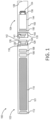
- the aerosol delivery device 100 can comprise a control body 102 and a cartridge 104 that can be permanently or detachably aligned in a functioning relationship. Engagement of the control body 102 and the cartridge 104 can be press fit (as illustrated), threaded, interference fit, magnetic, or the like.
- connection components such as further described herein may be used.
- the control body may include a coupler that is adapted to engage a connector on the cartridge.
- control body 102 and the cartridge 104 may be referred to as being disposable or as being reusable.
- the control body may have a replaceable battery or a rechargeable battery and thus may be combined with any type of recharging technology, including connection to a typical electrical outlet, connection to a car charger (i.e., cigarette lighter receptacle), and connection to a computer, such as through a universal serial bus (USB) cable.
- USB universal serial bus
- an adaptor including a USB connector at one end and a control body connector at an opposing end is disclosed in U.S. Pat. Pub. No. 2014/0261495 to Novak et al.
- the cartridge may comprise a single-use cartridge, as disclosed in U.S. Pat. No. 8,910,639 to Chang et al.
- a control body 102 can be formed of a control body shell 101 that can include a control component 106 (e.g., a printed circuit board (PCB), an integrated circuit, a memory component, a microcontroller, or the like), a flow sensor 108, a battery 110, and an LED 112, and such components can be variably aligned. Further indicators (e.g., a haptic feedback component, an audio feedback component, or the like) can be included in addition to or as an alternative to the LED. Additional representative types of components that yield visual cues or indicators, such as light emitting diode (LED) components, and the configurations and uses thereof, are described in U.S. Pat. Nos.
- LED light emitting diode
- a cartridge 104 can be formed of a cartridge shell 103 enclosing the reservoir 144 that is in fluid communication with a liquid transport element 136 adapted to wick or otherwise transport an aerosol precursor composition stored in the reservoir housing to a heater 134.
- a liquid transport element 136 adapted to wick or otherwise transport an aerosol precursor composition stored in the reservoir housing to a heater 134.
- Various embodiments of materials configured to produce heat when electrical current is applied therethrough may be employed to form the resistive heating element 134.
- Example materials from which the wire coil may be formed include Kanthal (FeCrAl), Nichrome, Molybdenum disilicide (MoSi 2 ), molybdenum silicide (MoSi), Molybdenum disilicide doped with Aluminum (Mo(Si,Al) 2 ), titanium, platinum, silver, palladium, graphite and graphite-based materials (e.g., carbon-based foams and yarns) and ceramics (e.g., positive or negative temperature coefficient ceramics).
- a heater may comprise a variety of materials configured to provide electromagnetic radiation, including laser diodes.
- An opening 128 may be present in the cartridge shell 103 (e.g., at the mouthend) to allow for egress of formed aerosol from the cartridge 104.
- Such components are representative of the components that may be present in a cartridge and are not intended to limit the scope of cartridge components that are encompassed by the present disclosure.
- the cartridge 104 also may include one or more electronic components 150, which may include an integrated circuit, a memory component, a sensor, or the like.
- the electronic component 150 may be adapted to communicate with the control component 106 and/or with an external device by wired or wireless means.
- the electronic component 150 may be positioned anywhere within the cartridge 104 or its base 140.
- control component 106 and the flow sensor 108 are illustrated separately, it is understood that the control component and the flow sensor may be combined as an electronic circuit board with the air flow sensor attached directly thereto. Further, the electronic circuit board may be positioned horizontally relative the illustration of FIG. 1 in that the electronic circuit board can be lengthwise parallel to the central axis of the control body.
- the air flow sensor may comprise its own circuit board or other base element to which it can be attached.
- a flexible circuit board may be utilized. A flexible circuit board may be configured into a variety of shapes, include substantially tubular shapes.
- the control body 102 and the cartridge 104 may include components adapted to facilitate a fluid engagement therebetween.
- the control body 102 can include a coupler 124 having a cavity 125 therein.
- the cartridge 104 can include a base 140 adapted to engage the coupler 124 and can include a projection 141 adapted to fit within the cavity 125. Such engagement can facilitate a stable connection between the control body 102 and the cartridge 104 as well as establish an electrical connection between the battery 110 and control component 106 in the control body and the heater 134 in the cartridge.
- control body shell 101 can include an air intake 118, which may be a notch in the shell where it connects to the coupler 124 that allows for passage of ambient air around the coupler and into the shell where it then passes through the cavity 125 of the coupler and into the cartridge through the projection 141.
- an air intake 118 which may be a notch in the shell where it connects to the coupler 124 that allows for passage of ambient air around the coupler and into the shell where it then passes through the cavity 125 of the coupler and into the cartridge through the projection 141.
- a coupler as seen in FIG. 1 may define an outer periphery 126 configured to mate with an inner periphery 142 of the base 140.
- the inner periphery of the base may define a radius that is substantially equal to, or slightly greater than, a radius of the outer periphery of the coupler.
- the coupler 124 may define one or more protrusions 129 at the outer periphery 126 configured to engage one or more recesses 178 defined at the inner periphery of the base.
- connection between the base 140 of the cartridge 104 and the coupler 124 of the control body 102 may be substantially permanent, whereas in other embodiments the connection therebetween may be releasable such that, for example, the control body may be reused with one or more additional cartridges that may be disposable and/or refillable.
- the aerosol delivery device 100 may be substantially rod-like or substantially tubular shaped or substantially cylindrically shaped in some embodiments. In other embodiments, further shapes and dimensions are encompassed - e.g., a rectangular or triangular cross-section, multifaceted shapes, or the like.
- the reservoir 144 illustrated in FIG. 1 can take on any design configured for retaining a liquid, such as a container or a mass configured for absorbing and/or adsorbing the liquid - e.g., a fibrous reservoir or a porous monolith, as presently described.
- the reservoir 144 can comprise one or more layers of nonwoven fibers substantially formed into the shape of a tube encircling the interior of the cartridge shell 103.
- An aerosol precursor composition can be retained in the reservoir 144.
- Liquid components for example, can be sorptively retained by the reservoir 144.
- the reservoir 144 can be in fluid connection with a liquid transport element 136.
- the liquid transport element 136 can transport the aerosol precursor composition stored in the reservoir 144 via capillary action to the heating element 134 that is in the form of a metal wire coil in this embodiment. As such, the heating element 134 is in a heating arrangement with the liquid transport element 136.
- the heating element 134 is activated, and the components for the aerosol precursor composition are vaporized by the heating element 134.
- Drawing upon the mouthend of the article 100 causes ambient air to enter the air intake 118 and pass through the cavity 125 in the coupler 124 and the central opening in the projection 141 of the base 140.
- the drawn air combines with the formed vapor to form an aerosol.
- the aerosol is whisked, aspirated, or otherwise drawn away from the heating element 134 and out the mouth opening 128 in the mouthend of the article 100.
- An input element may be included with the aerosol delivery device.
- the input may be included to allow a user to control functions of the device and/or for output of information to a user.
- Any component or combination of components may be utilized as an input for controlling the function of the device.
- one or more pushbuttons may be used as described in U.S. Pat. App. Ser. No. 14/193,961, filed February 28, 2014, to Worm et al .
- a touchscreen may be used as described in U.S. Pat. App. Ser. No. 14/643,626, filed March 10, 2015, to Sears et al .
- components adapted for gesture recognition based on specified movements of the aerosol delivery device may be used as an input. See U.S. Pat. App. Ser. No. 14/565,137, filed December 9, 2014, to Henry et al .
- an input may comprise a computer or computing device, such as a smartphone or tablet.
- the aerosol delivery device may be wired to the computer or other device, such as via use of a USB cord or similar protocol.
- the aerosol delivery device also may communicate with a computer or other device acting as an input via wireless communication. See, for example, the systems and methods for controlling a device via a read request as described in U.S. Pat. App. Ser. No. 14/327,776, filed July 10, 2014, to Ampolini et al .
- an APP or other computer program may be used in connection with a computer or other computing device to input control instructions to the aerosol delivery device, such control instructions including, for example, the ability to form an aerosol of specific composition by choosing the nicotine content and/or content of further flavors to be included.
- an aerosol delivery device can be chosen from components described in the art and commercially available.
- Examples of batteries that can be used according to the disclosure are described in U.S. Pat. Pub. No. 2010/0028766 to Peckerar et al .
- the aerosol delivery device can incorporate a sensor or detector for control of supply of electric power to the heat generation element when aerosol generation is desired (e.g., upon draw during use).
- a sensor or detector for control of supply of electric power to the heat generation element when aerosol generation is desired (e.g., upon draw during use).
- Additional representative types of sensing or detection mechanisms, structure and configuration thereof, components thereof, and general methods of operation thereof, are described in U.S. Pat. Nos. 5,261,424 to Sprinkel, Jr. ; 5,372,148 to McCafferty et al. ; and PCT WO 2010/003480 to Flick .
- the aerosol delivery device most preferably incorporates a control mechanism for controlling the amount of electric power to the heat generation element during draw.
- Representative types of electronic components, structure and configuration thereof, features thereof, and general methods of operation thereof, are described in U.S. Pat. Nos. 4,735,217 to Gerth et al. ; 4,947,874 to Brooks et al. ; 5,372,148 to McCafferty et al. ; 6,040,560 to Fleischhauer et al. ; 7,040,314 to Nguyen et al. and 8,205,622 to Pan ; U.S. Pat. Pub. Nos. 2009/0230117 to Fernando et al.
- the aerosol precursor composition most preferably incorporates tobacco or components derived from tobacco.
- the tobacco may be provided as parts or pieces of tobacco, such as finely ground, milled or powdered tobacco lamina.
- the tobacco may be provided in the form of an extract, such as a spray dried extract that incorporates many of the water soluble components of tobacco.
- tobacco extracts may have the form of relatively high nicotine content extracts, which extracts also incorporate minor amounts of other extracted components derived from tobacco.
- components derived from tobacco may be provided in a relatively pure form, such as certain flavoring agents that are derived from tobacco.
- a component that is derived from tobacco, and that may be employed in a highly purified or essentially pure form is nicotine (e.g., pharmaceutical grade nicotine).
- the aerosol precursor composition also referred to as a vapor precursor composition, may comprise a variety of components including, by way of example, a polyhydric alcohol (e.g., glycerin, propylene glycol, or a mixture thereof), nicotine, tobacco, tobacco extract, and/or flavorants.
- a polyhydric alcohol e.g., glycerin, propylene glycol, or a mixture thereof
- nicotine tobacco, tobacco extract, and/or flavorants.
- Representative types of aerosol precursor components and formulations also are set forth and characterized in U.S. Pat. No. 7,217,320 to Robinson et al. and U.S. Pat. Pub. Nos. 2013/0008457 to Zheng et al. ; 2013/0213417 to Chong et al. ; 2014/0060554 to Collett et al. ; 2015/0020823 to Lipowicz et al.
- aerosol precursors that may be employed include the aerosol precursors that have been incorporated in the VUSE ® product by R. J. Reynolds Vapor Company, the BLU TM product by Lorillard Technologies, the MISTIC MENTHOL product by Mistic Ecigs, and the VYPE product by CN Creative Ltd. Also desirable are the so-called "smoke juices" for electronic cigarettes that have been available from Johnson Creek Enterprises LLC.
- the amount of aerosol precursor that is incorporated within the aerosol delivery system is such that the aerosol generating piece provides acceptable sensory and desirable performance characteristics.
- sufficient amounts of aerosol forming material e.g., glycerin and/or propylene glycol
- the amount of aerosol precursor within the aerosol generating system may be dependent upon factors such as the number of puffs desired per aerosol generating piece.
- the amount of aerosol precursor incorporated within the aerosol delivery system, and particularly within the aerosol generating piece is less than about 2 g, generally less than about 1.5 g, often less than about 1 g and frequently less than about 0.5 g.
- the present disclosure relates to the use of a porous monolithic material in one or more components of an aerosol delivery device.
- a porous monolithic material or “porous monolith” is intended to mean comprising a substantially single unit which, in some embodiments, may be a single piece formed, composed, or created without joints or seams and comprising a substantially, but not necessarily rigid, uniform whole.
- a monolith according to the present disclosure may be undifferentiated, i.e., formed of a single material, or may be formed of a plurality of units that are permanently combined, such as a sintered conglomerate.
- porous glass is intended to refer to glass that has a three-dimensional interconnected porous microstructure.
- the term specifically can exclude materials made of bundles (i.e., wovens or non-wovens) of glass fibers.
- porous glass can exclude fibrous glass.
- Porous glass may also be referred to as controlled pore glass (CPG) and may be known by the trade name VYCOR ® .
- Porous glass suitable for use according to the present disclosure can be prepared by known methods such as, for example, metastable phase separation in borosilicate glasses followed by liquid extraction (e.g., acidic extraction or combined acidic and alkaline extraction) of one of the formed phases, via a sol-gel process, or by sintering of glass powder.
- the porous glass particularly can be a high-silica glass, such as comprising 90% or greater, 95%, 96% or greater, or 98% or greater silica by weight.
- Porous glass materials and methods of preparing porous glass that can be suitable for use according to the present disclosure are described in U.S. Pat. No. 2,106,744 to Hood et al. , U.S. Pat. No.
- the porous glass can be defined in some embodiments in relation to its average pore size.
- the porous glass can have an average pore size of about 1 nm to about 1000 ⁇ m, about 2 nm to about 500 ⁇ m, about 5 nm to about 200 ⁇ m, or about 10 nm to about 100 ⁇ m.
- porous glass for use according to the present disclosure can be differentiated based upon the average pore size.
- a small pore porous glass can have an average pore size of 1 nm up to 500 nm
- an intermediate pore porous class can have an average pore size of 500 nm up to 10 ⁇ m
- a large pore porous glass can have an average pore size of 10 ⁇ m up to 1000 ⁇ m.
- a large pore porous glass can preferably be useful as a storage element
- a small pore porous glass and/or an intermediate pore porous glass can preferably be useful as a transport element.
- the porous glass also can be defined in some embodiments in relation to its surface area.
- the porous glass can have a surface area of at least 100 m 2 /g, at least 150 m 2 /g, at least 200 m 2 /g, or at least 250 m 2 /g, such as about 100 m 2 /g to about 600 m 2 /g, about 150 m 2 /g to about 500 m 2 /g, or about 200 m 2 /g to about 450 m 2 /g.
- the porous glass can be defined in some embodiments in relation to its porosity (i.e., the volumetric fraction of the material encompassed by the pores).
- the porous glass can have a porosity of at least 20%, at least 25%, or at least 30%, such as about 20% to about 80%, about 25% to about 70%, or about 30% to about 60% by volume.
- a lower porosity may be desirable, such as a porosity of about 5% to about 50%, about 10% to about 40%, or about 15% to about 30% by volume.
- the porous glass can be further defined in some embodiments in relation to its density.
- the porous glass can have a density of 0.25 g/cm 3 to about 3 g/cm 3 , about 0.5 g/cm 3 to about 2.5 g/cm 3 , or about 0.75 g/cm 3 to about 2 g/cm 3 .
- porous ceramic is intended to refer to a ceramic material that has a three-dimensional interconnected porous microstructure. Porous ceramic materials and methods of making porous ceramics suitable for use according to the present disclosure are described in U.S. Pat. No. 3,090,094 to Schwartzwalder et al. , U.S. Pat. No. 3,833,386 to Frisch et al. , U.S. Pat. No. 4,814,300 to Helferich , U.S. Pat. No. 5,171,720 to Kawakami , U.S. Pat. No.
- the porous ceramic likewise can be defined in some embodiments in relation to its average pore size.
- the porous ceramic can have an average pore size of about 1 nm to about 1000 ⁇ m, about 2 nm to about 500 ⁇ m, about 5 nm to about 200 ⁇ m, or about 10 nm to about 100 ⁇ m.
- porous ceramic for use according to the present disclosure can be differentiated based upon the average pore size.
- a small pore porous ceramic can have an average pore size of 1 nm up to 500 nm
- an intermediate pore porous ceramic can have an average pore size of 500 nm up to 10 ⁇ m
- a large pore porous ceramic can have an average pore size of 10 ⁇ m up to 1000 ⁇ m.
- a large pore porous ceramic can preferably be useful as a storage element
- a small pore porous ceramic and/or an intermediate pore porous ceramic can preferably be useful as a transport element.
- the porous ceramic also can be defined in some embodiments in relation to its surface area.
- the porous ceramic can have a surface area of at least 100 m 2 /g, at least 150 m 2 /g, at least 200 m 2 /g, or at least 250 m 2 /g, such as about 100 m 2 /g to about 600 m 2 /g, about 150 m 2 /g to about 500 m 2 /g, or about 200 m 2 /g to about 450 m 2 /g.
- the porous ceramic can be defined in some embodiments in relation to its porosity (i.e., the volumetric fraction of the material encompassed by the pores).
- the porous ceramic can have a porosity of at least 20%, at least 25%, or at least 30%, such as about 20% to about 80%, about 25% to about 70%, or about 30% to about 60% by volume.
- a lower porosity may be desirable, such as a porosity of about 5% to about 50%, about 10% to about 40%, or about 15% to about 30% by volume.
- the porous ceramic can be further defined in some embodiments in relation to its density.
- the porous ceramic can have a density of 0.25 g/cm 3 to about 3 g/cm 3 , about 0.5 g/cm 3 to about 2.5 g/cm 3 , or about 0.75 g/cm 3 to about 2 g/cm 3 .
- a porous monolith in some embodiments, can comprise a variety of aluminosilicate materials.
- various zeolites may be utilized according to the present disclosure.
- a porous monolith used according to the present disclosure can be provided in a variety of sizes and shapes.
- the porous monolith may be substantially elongated, substantially flattened or planar, substantially curved (e.g., "U-shaped"), substantially in the form of a walled cylinder, or in any other form suitable for use according to the present disclosure.
- a porous monolith according to the present disclosure can be characterized in relation to wicking rate.
- wicking rate can be calculated by measuring the mass uptake of a known liquid, and the rate (in mg/s) can be measured using a microbalance tensiometer or similar instrument.
- the wicking rate is substantially within the range of the desired mass of aerosol to be produced over the duration of a puff on an aerosol forming article including the porous monolith.
- Wicking rate can be, for example, in the range of about 0.05 mg/s to about 15 mg/s, about 0.1 mg/s to about 12 mg/s, or about 0.5 mg/s to about 10 mg/s.
- Wicking rate can vary based upon the liquid being wicked.
- wicking rates as described herein can be referenced to substantially pure water, substantially pure glycerol, substantially pure propylene glycol, a mixture of water and glycerol, a mixture of water and propylene glycol, a mixture of glycerol and propylene glycol, or a mixture of water, glycerol, and propylene glycol.
- Wicking rate also can vary based upon the use of the porous monolith. For example, a porous monolith used as a liquid transport element may have a greater wicking rate than a porous monolith used as a reservoir. Wicking rates may be varied by control of one or more of pore size, pore size distribution, and wettability, as well as the composition of the material being wicked.
- FIG. 2 An exemplary embodiment of the present disclosure in relation to a porous monolith is illustrated in FIG. 2 .
- a liquid transport element 236 is surrounded by and in contact with a reservoir 244.
- a liquid transport element or a reservoir can be characterized as being a vapor substrate.
- the term "vapor substrate" thus refers to a substrate that stores and/or transports a liquid for vaporization and which can be in contact with a heater for vaporization of at least a portion of the liquid that is stored and/or transported by the vapor substrate.
- a single porous monolith may function as a reservoir that can be in direct contact with a heater to provide for vapor formation without the need for a separate liquid transport element (or wick).
- the reservoir would be considered a vapor substrate.
- a separate liquid transport element may be in contact with a heater and in contact with a separate reservoir so that liquid is transported from the reservoir to the heater for vaporization. In such instances, the liquid transport element would be considered a vapor substrate.
- a reservoir is otherwise discussed herein, it is understood that such reservoir may properly be characterized as being a vapor substrate.
- a liquid transport element is otherwise discussed herein, it is understood that such liquid transport element may properly be characterized as being a vapor substrate.
- the porous monolith can comprise a porous glass.
- either or both of the liquid transport element 236 and the reservoir 244 can be a porous glass as described herein.
- both of the liquid transport element 236 and the reservoir 244 are formed of porous glass and, preferentially, they may each be formed of a different porous glass (i.e., a first porous glass and a second porous glass).
- the first porous glass and the second porous glass can differ in one or more characteristics that can affect the storage and/or transport ability of the respective porous glass. For example, they may differ in one or more of density, porosity, surface area, and average pore size.
- the differential between the liquid transport element 236 and the reservoir 244 is sufficient to provide a wicking gradient wherein wicking ability is greater in the liquid transport element than in the reservoir.
- Such configuration may be characterized as a gradient porosity or a dual porosity configuration.
- the porous monolith can comprise a porous ceramic.
- one or both of the liquid transport element 236 and the reservoir 244 may be formed of porous ceramic.
- one of the liquid transport element 236 and the reservoir 244 may be formed of porous glass, and the other of the liquid transport element and the reservoir may be formed of porous ceramic.
- the porous glass and the porous ceramic can have properties that are substantially matched to provide substantially identical flow characteristics, or the porous glass and the porous ceramic can have properties that are substantially different to provide substantially different flow characteristics.
- a heater 234 is positioned relative to the liquid transport element 236 so as to be configured for vaporization of liquid aerosol precursor material that can be stored in the reservoir 244 and transported therefrom to the heater by the liquid transport element.
- the heater 234 can be, for example, a printed microheater, an annealed microheater, a flat ribbon heater, or any similar configuration suitable for vaporization of an aerosol precursor composition as otherwise described herein.
- the heater 234 may be in direct contact with the liquid transport element 236 or may be in a radiant heating configuration relative to the liquid transport element - i.e., in very close proximity to, but not directly touching the liquid transport element.
- supplemental liquid may be wicked from the reservoir 244 to the proximity of the heater 234 by the liquid transport element and fill the area where the liquid was depleted by vaporization.
- one or more etchings may be present on one or both of the reservoir 244 and the liquid transport element 236.
- the grooves or channels may be formed by an etching process, use of the term “etchings” is not meant to be limiting of the process by which the grooves or channels are formed.
- a first set of grooves 256 is etched into the liquid transport element 236 around the heater 234. The first set of grooves 256 is useful to limit direct contact of the liquid aerosol precursor composition with the heater 234.
- the porous monolith may be insulated, coated, or sealed to prevent the liquid aerosol precursor composition form coming into direct contact with the heater, which could function to damage the heater.
- a second set of grooves 254 may be etched in the surface of the reservoir 244 so that the liquid aerosol precursor composition is substantially directed toward the central area of the heater where Joule heating is at a maximum.
- the second set of grooves 254 may substantially align with and/or interconnect with the first set of grooves 256.
- the presence of the second set of grooves 254 is not dependent upon the presence of the first set of grooves 256 and vice versa.
- the combination of the heater 234, liquid transport element 236, and reservoir 244 may be characterized as an atomizer 20.
- the reservoir 244 may be absent from the atomizer 20.
- reservoir 244 and liquid transport element 236 are illustrated as separate elements, such separation is not required.
- a single porous monolith substrate may be utilized and area treatments may provide for differentiation between a reservoir area and a liquid transport area.
- the reservoir 244 and liquid transport element 236 are illustrated in FIG. 2 as being substantially planar, other shapes are also encompassed.
- the reservoir and liquid transport element may independently be cylindrical, flat, oval-shaped, circular, square, rectangular, or the like.
- at least a portion of a surface of at least the liquid transport element is substantially flat to provide a location for placement of the heater.
- FIG. 3 Such embodiments are exemplified in FIG. 3 , wherein the reservoir 344 is substantially in the form of a half cylinder.
- the liquid transport element 336 is inset in the flat surface 344a of the reservoir; however, the liquid transport element may be layered on the flat surface of the reservoir.
- the heater 334 is positioned on the liquid transport element 336, and etchings 356 are present in the liquid transport element.
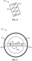
- the heater 434 can comprise a heater substrate 434a upon which a heater trace 434b is provided.
- the heater substrate 434a is preferably a chemically stable and heat-resistant material (e.g., silicon or glass), and the heater trace 434b can be a material suitable for rapid heating, such as a heating wire as otherwise described herein.
- An atomizer 20 as illustrated in FIG. 2 can be incorporated into a cartridge 104 as seen in FIG. 1 .
- the atomizer 20 may be included in place of the heater 134, the liquid transport element 136, and optionally the reservoir 144. In some embodiments, the atomizer 20 may simply be included in addition to the further elements illustrated in FIG. 1 .
- a porous monolith may be used as the liquid transport element alone.
- a cartridge 504 is formed of a shell 503 and a reservoir 544 that is holding a liquid aerosol precursor composition.
- the reservoir 544 may be a fibrous mat into which the liquid is absorbed or may be a container with suitable openings therein to receive the liquid transport element 536.
- the liquid transport element 536 is formed of a porous monolith and has respective ends 536a and 536b that extend into the reservoir 544.
- a heater 534 in the form of a resistive heating wire is wrapped around the liquid transport element 536 at an approximate middle section 536c thereof, and the wire includes terminals 535 for making an electrical connection with a power source.
- the liquid transport element 536 can be a porous glass. In further embodiments, the liquid transport element 536 can be a porous ceramic. In one or more embodiments, one or both of the liquid transport element 536 and the reservoir 544 can be a porous glass, or one or both of the liquid transport element and the reservoir can be a porous ceramic. In some embodiments, one of the liquid transport element 536 and the reservoir 544 can be a porous glass, and the other of the liquid transport element and the reservoir can be a porous ceramic.
- a liquid transport element according to the present disclosure can be substantially in a core/shell form.
- a core 636a can have at least a portion thereof surrounded with a shell 636b, which can be formed of a porous monolith.
- the core 636a may also be formed of a porous monolith.
- the core 636a may be formed of a porous glass with one or more different properties from the porous glass forming the shell 636b so that differential characteristics of the combined elements may be provided.
- the core 636a may be formed of a porous glass configured for improved storage of a liquid
- the shell 636b may be formed of a porous glass configured for improved transport of the liquid for rapid wicking to the heater 634 that can be a wire that is substantially wrapped around the shell.
- the core 636a may be formed of a material other than porous glass, such as a fibrous material.
- the core 636a may be formed of a glass fiber, cotton, cellulose acetate, or like materials.
- one or both of the core 636a and the shell 636b can be formed of a porous ceramic.
- one of the core 636a and the shell 636b can be formed of a porous glass, and the other of the core and the shell can be formed of a porous ceramic.
- the porous monolith shell 636b has opposing ends 636b' and 636b", and the core 636a is sized so that it extends beyond the opposing ends of the porous monolith shell.
- One or both of the ends 636a' and 636a" of the core 636a can be positioned in an aerosol delivery device so as to extend into a reservoir (e.g., a fibrous mat or a bulk liquid storage container) and thus wick liquid to the shell 636b so that the liquid is vaporized by the heater 634.
- the heater 634 can include terminals 635 for making an electrical connection with a power source.
- Such core/shell design can be particularly beneficial in that the core material can be shielded from potential scorching by the high heat provided by the heating wire.
- air flow for entraining formed vapor may pass substantially across the porous monolith shell and have little or substantially no direct flow across the core material.
- FIG. 6 The combination of elements in FIG. 6 may be characterized collectively as an atomizer 60. Nevertheless, it is understood that one or more of the elements (e.g., the core 636a and/or the shell 636b and/or the heater 634) may be utilized separate from the unit in combination with one or more further embodiments described herein.
- the elements e.g., the core 636a and/or the shell 636b and/or the heater 634
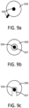
- a porous monolith can be used as a reservoir that can be substantially shaped as a cylinder.
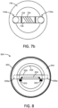
- FIG. 7a and FIG. 7b illustrate an atomizer 70 comprising a reservoir 744 formed of a porous monolith that is shaped as a cylinder.
- the reservoir 744 has a wall 745 with a thickness that can vary, and a central opening 746 is defined by the wall.
- a liquid transport element 736 is configured with a central portion 736c and respective end portions 736a' and 736a" extending away from the central portion.
- the respective end portions 736a' and 736a" are configured to be in fluid connection with the wall 745 of the reservoir 744.
- the liquid transport element 736 and the reservoir 744 can be formed of a porous glass.
- the liquid transport element 736 may be formed of porous glass with one or more properties that are different from the properties of the porous glass forming the reservoir 744.
- the liquid transport element 736 can be formed of a fibrous material and thus may be referred to as a fibrous wick.
- a heater 734 in the form of a wire is wrapped around the central portion 736c of the liquid transport element 736 can include terminals 735 for making an electrical connection with a power source.
- one or both of the liquid transport element 736 and the reservoir 744 can be formed of a porous ceramic.
- one of the liquid transport element 736 and the reservoir 744 can be formed of a porous glass, and the other of the liquid transport element and the reservoir can be formed of a porous ceramic.
- the reservoir wall 745 can include one or more grooves 744a.
- the respective end portions 736a' and 736a" of the liquid transport element 736 in particular may engage the reservoir 744 in the grooves 744a.
- the grooves 744a can be configured to have one or more properties that are different that the remaining sections of the reservoir, such as having a different porosity. In this manner, liquid stored in the reservoir 744 can be preferentially directed toward the grooves 744a to be taken up by the liquid transport element 736 for delivery to the heater 734.
- a porous monolith forming a liquid transport element can have a heating member contained therein.
- a cartridge 804 is formed of a shell 803 and a reservoir 844 that is holding a liquid aerosol precursor composition.
- the reservoir 844 may be a fibrous mat into which the liquid is absorbed or may be a walled container with suitable openings therein to receive the liquid transport element 836.
- the liquid transport element 836 is formed of a porous monolith and has respective ends 836a and 836b that extend into the reservoir 844.
- a heater 834 in the form of a resistive heating wire is positioned within the liquid transport element 836, and the wire includes terminals 835 for making an electrical connection with a power source.
- a flow tube 839 is included and can be useful for directing air across the liquid transport element 836 so that vapor evolved by internal heating of the liquid transport element by the heater 834 becomes entrained in the air to form an aerosol that can be withdrawn by a consumer.
- the liquid transport element 836 can be a porous glass.
- the liquid transport element 836 can be a porous ceramic.
- one or both of the liquid transport element 836 and the reservoir 844 can be a porous glass, or one or both of the liquid transport element and the reservoir can be a porous ceramic.
- one of the liquid transport element 836 and the reservoir 844 can be a porous glass, and the other of the liquid transport element and the reservoir can be a porous ceramic. Further, the liquid transport element 844 can be a porous glass or a porous ceramic, and the reservoir 844 can be a fibrous mat or a storage container.
- the heater 834 can be included within the liquid transport element 836 in a variety of manners.
- the heater can be embedded within the porous monolith.
- the porous monolith can be formed with the heater in place so that the heater is substantially entrapped within the liquid transport element.
- the heater 934 is embedded in the liquid transport element 936, and an end of the heater extends out from the liquid transport element to make electrical connection with the terminals (see element 835 in FIG. 8 ).
- the porous monolith can be hollow, can be substantially in the form or a tube, can have a slot, channel, or the like formed therein, or can otherwise include a void into which the heater is place so as to be substantially internal to the liquid transport element.
- the liquid transport element 936 is a hollow tube, and the heater 934 is positioned within a cavity 937 of the hollow tube.
- the liquid transport element 936 includes a cavity 937 substantially in the form of a channel along at least a portion of the length of the liquid transport element, and the heater 934 is positioned in the cavity.
- the heater that is internal to the liquid transport element can be in direct contact with at least a portion of the liquid transport element so as to provide conductive heating thereof.
- the heater that is internal to the liquid transport element can be substantially, predominately, or approximately completely in a radiative heating relationship with the liquid transport element.
- a substantially radiative heating relationship can mean that radiative heating occurs but does not provide a majority of the heating - e.g., 50% or less of the heating is radiative heating but a measurable quantity of the heating is radiative.
- a predominately radiative heating relationship can mean that radiative heating provides a majority of the heating but not all of the heating - i.e., greater than 50% of the heating is radiative.
- An approximately complete radiative heating relationship can mean that at least 90%, preferably at least 95%, and more preferably at least 98% or at least 99% of the heating is radiative.
Landscapes
- Chemical & Material Sciences (AREA)
- Chemical Kinetics & Catalysis (AREA)
- General Chemical & Material Sciences (AREA)
- Physics & Mathematics (AREA)
- Electromagnetism (AREA)
- Medicinal Preparation (AREA)
- Physical Or Chemical Processes And Apparatus (AREA)
- Glass Compositions (AREA)
- Catching Or Destruction (AREA)
- Resistance Heating (AREA)
- Chemical Vapour Deposition (AREA)
- Feeding, Discharge, Calcimining, Fusing, And Gas-Generation Devices (AREA)
- Disinfection, Sterilisation Or Deodorisation Of Air (AREA)
- Coating By Spraying Or Casting (AREA)
- Nozzles (AREA)
- Special Spraying Apparatus (AREA)
Claims (11)
- Verdampfer für eine Aerosolabgabevorrichtung, wobei der Verdampfer Folgendes umfasst:einen einzelnen porösen Monolith, der aus einer Keramik gebildet ist, wobei der poröse Monolith einen Reservoirbereich zum Halten einer Aerosolvorläuferzusammensetzung und einen Flüssigkeitstransportbereich mit einem im Wesentlichen flachen Flächenabschnitt aufweist, der dahingehend betreibbar ist, die Aerosolvorläuferzusammensetzung aus dem Reservoirbereich zu dem im Wesentlichen flachen Flächenabschnitt zu transportieren, undeine Heizung, die mindestens teilweise auf dem im Wesentlichen flachen Flächenabschnitt des Flüssigkeitstransportbereichs des einzelnen porösen Monoliths positioniert ist, um die Aerosolvorläuferzusammensetzung an dem im Wesentlichen flachen Flächenabschnitt des Flüssigkeitstransportbereichs zu verdampfen.
- Verdampfer nach Anspruch 1, wobei der poröse Monolith einen im Wesentlichen quadratischen oder im Wesentlichen rechteckigen Querschnitt aufweist.
- Verdampfer nach Anspruch 1 oder 2, wobei die Heizung auf den einzelnen porösen Keramikmonolith aufgedruckt ist.
- Verdampfer nach Anspruch 1 oder 2, wobei die Heizung durch Annealing mit dem einzelnen porösen Keramikmonolith verbunden ist.
- Verdampfer nach Anspruch 1 oder 2, wobei die Heizung eine Flachbandheizung ist.
- Verdampfer nach einem der Ansprüche 1 - 5, ferner umfassend ein Reservoir, das von dem porösen Monolith getrennt ist.
- Verdampfer nach Anspruch 6, wobei der Reservoirbereich die Aerosolvorläuferzusammensetzung aus dem Reservoir empfängt.
- Verdampfer nach Anspruch 6 oder 7, wobei der poröse Monolith eine oder mehrere Ätzungen aufweist.
- Aerosolabgabevorrichtung, umfassend:ein Außengehäuse undden Verdampfer nach einem der Ansprüche 1 - 8.
- Aerosolabgabevorrichtung nach Anspruch 9, ferner umfassend einen Lufteinlass, ein Mundende und eine in dem Mundende ausgebildete Aerosolöffnung.
- Aerosolabgabevorrichtung nach Anspruch 10, wobei ein zwischen dem Lufteinlass und der Aerosolöffnung strömender Luftstrom, dazu ausgestaltet ist, im Wesentlichen über eine Oberfläche des porösen Monoliths zu strömen.
Priority Applications (1)
| Application Number | Priority Date | Filing Date | Title |
|---|---|---|---|
| EP25175623.5A EP4576939A3 (de) | 2016-01-05 | 2017-01-04 | Aerosolabgabevorrichtung mit verbessertem flüssigkeitstransport |
Applications Claiming Priority (3)
| Application Number | Priority Date | Filing Date | Title |
|---|---|---|---|
| US14/988,109 US10194694B2 (en) | 2016-01-05 | 2016-01-05 | Aerosol delivery device with improved fluid transport |
| PCT/IB2017/050025 WO2017118927A1 (en) | 2016-01-05 | 2017-01-04 | Aerosol delivery device with improved fluid transport |
| EP17701182.2A EP3402348B1 (de) | 2016-01-05 | 2017-01-04 | Aerosolerzeugungsvorrichtung mit verbessertem flüssigkeitstransport |
Related Parent Applications (2)
| Application Number | Title | Priority Date | Filing Date |
|---|---|---|---|
| EP17701182.2A Division EP3402348B1 (de) | 2016-01-05 | 2017-01-04 | Aerosolerzeugungsvorrichtung mit verbessertem flüssigkeitstransport |
| EP17701182.2A Division-Into EP3402348B1 (de) | 2016-01-05 | 2017-01-04 | Aerosolerzeugungsvorrichtung mit verbessertem flüssigkeitstransport |
Related Child Applications (1)
| Application Number | Title | Priority Date | Filing Date |
|---|---|---|---|
| EP25175623.5A Division EP4576939A3 (de) | 2016-01-05 | 2017-01-04 | Aerosolabgabevorrichtung mit verbessertem flüssigkeitstransport |
Publications (3)
| Publication Number | Publication Date |
|---|---|
| EP3714719A2 EP3714719A2 (de) | 2020-09-30 |
| EP3714719A3 EP3714719A3 (de) | 2021-02-24 |
| EP3714719B1 true EP3714719B1 (de) | 2025-05-14 |
Family
ID=57868294
Family Applications (3)
| Application Number | Title | Priority Date | Filing Date |
|---|---|---|---|
| EP17701182.2A Active EP3402348B1 (de) | 2016-01-05 | 2017-01-04 | Aerosolerzeugungsvorrichtung mit verbessertem flüssigkeitstransport |
| EP25175623.5A Pending EP4576939A3 (de) | 2016-01-05 | 2017-01-04 | Aerosolabgabevorrichtung mit verbessertem flüssigkeitstransport |
| EP20174946.2A Active EP3714719B1 (de) | 2016-01-05 | 2017-01-04 | Aerosolausgabevorrichtung mit verbessertem fluidtransport |
Family Applications Before (2)
| Application Number | Title | Priority Date | Filing Date |
|---|---|---|---|
| EP17701182.2A Active EP3402348B1 (de) | 2016-01-05 | 2017-01-04 | Aerosolerzeugungsvorrichtung mit verbessertem flüssigkeitstransport |
| EP25175623.5A Pending EP4576939A3 (de) | 2016-01-05 | 2017-01-04 | Aerosolabgabevorrichtung mit verbessertem flüssigkeitstransport |
Country Status (15)
| Country | Link |
|---|---|
| US (3) | US10194694B2 (de) |
| EP (3) | EP3402348B1 (de) |
| JP (3) | JP2019506896A (de) |
| KR (2) | KR102665213B1 (de) |
| CN (2) | CN112956752A (de) |
| BR (1) | BR112018013700B1 (de) |
| CA (1) | CA3010444A1 (de) |
| ES (1) | ES2813601T3 (de) |
| HU (1) | HUE050425T2 (de) |
| MY (1) | MY193237A (de) |
| PH (1) | PH12018501440A1 (de) |
| PL (2) | PL3402348T3 (de) |
| RU (1) | RU2741896C2 (de) |
| UA (2) | UA124700C2 (de) |
| WO (1) | WO2017118927A1 (de) |
Families Citing this family (98)
| Publication number | Priority date | Publication date | Assignee | Title |
|---|---|---|---|---|
| US20160345631A1 (en) | 2005-07-19 | 2016-12-01 | James Monsees | Portable devices for generating an inhalable vapor |
| US10279934B2 (en) | 2013-03-15 | 2019-05-07 | Juul Labs, Inc. | Fillable vaporizer cartridge and method of filling |
| USD842536S1 (en) | 2016-07-28 | 2019-03-05 | Juul Labs, Inc. | Vaporizer cartridge |
| US10058129B2 (en) | 2013-12-23 | 2018-08-28 | Juul Labs, Inc. | Vaporization device systems and methods |
| USD825102S1 (en) | 2016-07-28 | 2018-08-07 | Juul Labs, Inc. | Vaporizer device with cartridge |
| US20160366947A1 (en) | 2013-12-23 | 2016-12-22 | James Monsees | Vaporizer apparatus |
| US10076139B2 (en) | 2013-12-23 | 2018-09-18 | Juul Labs, Inc. | Vaporizer apparatus |
| US10159282B2 (en) | 2013-12-23 | 2018-12-25 | Juul Labs, Inc. | Cartridge for use with a vaporizer device |
| PL3513673T3 (pl) | 2013-12-23 | 2024-07-08 | Juul Labs International Inc. | Sposoby, układy i urządzenie do odparowywania |
| CN104161308A (zh) * | 2014-09-04 | 2014-11-26 | 昂纳自动化技术(深圳)有限公司 | 电子烟雾化器发热模块 |
| EP4464356A3 (de) | 2014-12-05 | 2025-01-08 | Juul Labs, Inc. | Kalibrierte dosissteuerung |
| ES2887242T3 (es) * | 2015-06-25 | 2021-12-22 | Fontem Holdings 2 Bv | Dispositivo electrónico para fumar y atomizador |
| SG10202108578XA (en) | 2016-02-11 | 2021-09-29 | Juul Labs Inc | Securely attaching cartridges for vaporizer devices |
| UA125687C2 (uk) | 2016-02-11 | 2022-05-18 | Джуул Лебз, Інк. | Заповнювальний картридж випарного пристрою та способи його заповнення |
| US10405582B2 (en) | 2016-03-10 | 2019-09-10 | Pax Labs, Inc. | Vaporization device with lip sensing |
| US12201767B2 (en) | 2016-04-22 | 2025-01-21 | Juul Labs, Inc. | Aerosol devices having compartmentalized materials |
| US10772354B2 (en) * | 2016-05-31 | 2020-09-15 | Altria Client Services Llc | Heater and wick assembly for an aerosol generating system |
| USD849996S1 (en) | 2016-06-16 | 2019-05-28 | Pax Labs, Inc. | Vaporizer cartridge |
| USD836541S1 (en) | 2016-06-23 | 2018-12-25 | Pax Labs, Inc. | Charging device |
| USD851830S1 (en) | 2016-06-23 | 2019-06-18 | Pax Labs, Inc. | Combined vaporizer tamp and pick tool |
| US9795169B1 (en) * | 2016-07-05 | 2017-10-24 | Xiaochun Zhu | Replaceable vaporizer assembly and electronic cigarette having the same |
| US10617151B2 (en) * | 2016-07-21 | 2020-04-14 | Rai Strategic Holdings, Inc. | Aerosol delivery device with a liquid transport element comprising a porous monolith and related method |
| US10602775B2 (en) | 2016-07-21 | 2020-03-31 | Rai Strategic Holdings, Inc. | Aerosol delivery device with a unitary reservoir and liquid transport element comprising a porous monolith and related method |
| US11234465B2 (en) * | 2017-01-31 | 2022-02-01 | Ahkeo Labs, Llc | Heating mechanisms for vaporizers |
| US10674765B2 (en) * | 2017-03-29 | 2020-06-09 | Rai Strategic Holdings, Inc. | Aerosol delivery device with improved atomizer |
| US11576424B2 (en) * | 2017-04-05 | 2023-02-14 | Altria Client Services Llc | Susceptor for use with an inductively heated aerosol-generating device or system |
| BR112019019961A2 (pt) | 2017-04-05 | 2020-04-28 | Philip Morris Products Sa | susceptor para uso com um dispositivo ou sistema gerador de aerossol indutivamente aquecido |
| US10314340B2 (en) * | 2017-04-21 | 2019-06-11 | Rai Strategic Holdings, Inc. | Refillable aerosol delivery device and related method |
| GB2561867B (en) | 2017-04-25 | 2021-04-07 | Nerudia Ltd | Aerosol delivery system |
| EP3415439B1 (de) * | 2017-06-13 | 2021-08-04 | HS Marston Aerospace Limited | Verfahren und vorrichtung zur kraftstoffverdampfung in katalytischer kraftstofftankinertisierung |
| US10701977B2 (en) * | 2017-08-09 | 2020-07-07 | Vuber Technologies, Inc. | Permeable element based vaporization process and device |
| CA3074463A1 (en) | 2017-08-28 | 2019-03-07 | Juul Labs, Inc. | Wick for vaporizer device |
| CN107454697A (zh) * | 2017-09-09 | 2017-12-08 | 深圳市余看智能科技有限公司 | 一种用于加热不燃烧烟草的分段加热陶瓷发热管 |
| USD887632S1 (en) | 2017-09-14 | 2020-06-16 | Pax Labs, Inc. | Vaporizer cartridge |
| DE102017123867A1 (de) * | 2017-10-13 | 2019-04-18 | Hauni Maschinenbau Gmbh | Inhalator, insbesondere elektronisches Zigarettenprodukt, und Computerprogrammprodukt |
| DE102017123866A1 (de) | 2017-10-13 | 2019-04-18 | Hauni Maschinenbau Gmbh | Inhalator, insbesondere elektronisches Zigarettenprodukt |
| US10786010B2 (en) * | 2017-12-15 | 2020-09-29 | Rai Strategic Holdings, Inc. | Aerosol delivery device with multiple aerosol delivery pathways |
| CN108095203A (zh) * | 2018-02-09 | 2018-06-01 | 昆明纳太科技有限公司 | 一种电加热不燃烧卷烟用辐射式加热装置 |
| EP3758531A1 (de) | 2018-02-27 | 2021-01-06 | Juul Labs, Inc. | Massenausgangsgesteuerter verdampfer |
| CN209768986U (zh) * | 2018-05-04 | 2019-12-13 | 深圳麦克韦尔科技有限公司 | 电子烟及其雾化装置 |
| US10932490B2 (en) * | 2018-05-16 | 2021-03-02 | Rai Strategic Holdings, Inc. | Atomizer and aerosol delivery device |
| CN108741229B (zh) * | 2018-05-29 | 2021-01-12 | 深圳市新宜康科技股份有限公司 | 气雾发生装置的制作方法 |
| CN112312785B (zh) | 2018-06-07 | 2025-06-06 | 尤尔实验室有限公司 | 用于蒸发器装置的料盒 |
| CN208875406U (zh) * | 2018-07-17 | 2019-05-21 | 深圳市合元科技有限公司 | 雾化器及电子烟 |
| FR3083983A1 (fr) | 2018-07-23 | 2020-01-24 | Juul Labs, Inc. | Gestion d’écoulement d’air pour dispositif de vaporisateur |
| US20200077703A1 (en) * | 2018-09-11 | 2020-03-12 | Rai Strategic Holdings, Inc. | Wicking element for aerosol delivery device |
| CN108887753A (zh) * | 2018-09-17 | 2018-11-27 | 苏州晶品新材料股份有限公司 | 一种无机三维储油体、雾化装置及电子烟 |
| US10791767B2 (en) | 2018-10-12 | 2020-10-06 | Rai Strategic Holdings, Inc. | Connectors for forming electrical and mechanical connections between interchangeable units in an aerosol delivery system |
| US12171261B2 (en) * | 2018-10-12 | 2024-12-24 | Rai Strategic Holdings, Inc. | Vaporization system |
| US12256784B2 (en) | 2018-10-17 | 2025-03-25 | Juul Labs, Inc. | Cartridge for a vaporizer device |
| EP4393336A3 (de) | 2018-11-08 | 2024-10-09 | Juul Labs, Inc. | Verdampfervorrichtung mit mehr als einem heizelement |
| DE102018130106B4 (de) * | 2018-11-28 | 2025-04-24 | Körber Technologies Gmbh | Verdampfervorrichtung, Verbrauchseinheit, Inhalator und Verfahren zur Herstellung von elektrisch beheizbaren Heizkörpern und Dichtungsträgern |
| CN209376696U (zh) * | 2018-11-29 | 2019-09-13 | 深圳市合元科技有限公司 | 电子烟雾化器及包含该电子烟雾化器的电子烟 |
| CN209546930U (zh) * | 2018-12-13 | 2019-10-29 | 常州市派腾电子技术服务有限公司 | 雾化头、雾化器及电子烟 |
| DE102019202046A1 (de) * | 2019-02-15 | 2020-08-20 | Hauni Maschinenbau Gmbh | Verdampfer-Tank-Einheit für einen Inhalator, vorzugsweise, ein elektronisches Zigarettenprodukt, elektronisches Zigarettenprodukt und Dochtstruktur |
| EP3935975A4 (de) * | 2019-03-08 | 2022-10-12 | Japan Tobacco Inc. | Inhalationsvorrichtungskartusche und damit ausgestattete inhalationsvorrichtung |
| JP6858318B2 (ja) * | 2019-03-08 | 2021-04-14 | 日本たばこ産業株式会社 | 非燃焼型香味吸引器用の蒸気生成ユニット及びその製造方法 |
| US11602164B2 (en) * | 2019-03-14 | 2023-03-14 | Rai Strategic Holdings, Inc. | Aerosol delivery device with graded porosity from inner to outer wall surfaces |
| US12458070B2 (en) | 2019-03-21 | 2025-11-04 | Imperial Tobacco Limited | Aerosol delivery system |
| US11517688B2 (en) * | 2019-05-10 | 2022-12-06 | Rai Strategic Holdings, Inc. | Flavor article for an aerosol delivery device |
| US12396480B2 (en) | 2019-05-22 | 2025-08-26 | Rai Strategic Holdings, Inc. | Reservoir configuration for aerosol delivery device |
| US11589425B2 (en) | 2019-05-24 | 2023-02-21 | Rai Strategic Holdings, Inc. | Shape memory material for controlled liquid delivery in an aerosol delivery device |
| EP3987957A4 (de) * | 2019-06-18 | 2023-08-30 | Japan Tobacco Inc. | Heizteil und inhalator ohne verbrennung |
| PL3989758T3 (pl) * | 2019-06-25 | 2023-12-04 | Philip Morris Products S.A. | Układ wytwarzania aerozolu i wkład do układu wytwarzania aerozolu posiadający ulepszony zespół grzejny |
| CN112167725B (zh) * | 2019-07-03 | 2023-03-14 | 深圳市合元科技有限公司 | 一种有机多孔材料在气溶胶发生装置中的用途及使用该材料的雾化器 |
| KR102386859B1 (ko) * | 2019-07-30 | 2022-04-14 | 주식회사 케이티앤지 | 무화기 및 이를 포함하는 카트리지 |
| CN110477456B (zh) * | 2019-08-02 | 2024-07-16 | 深圳麦克韦尔科技有限公司 | 多孔结构组件和电子烟 |
| US11207711B2 (en) | 2019-08-19 | 2021-12-28 | Rai Strategic Holdings, Inc. | Detachable atomization assembly for aerosol delivery device |
| US11889861B2 (en) | 2019-09-23 | 2024-02-06 | Rai Strategic Holdings, Inc. | Arrangement of atomization assemblies for aerosol delivery device |
| US12414586B2 (en) | 2019-10-18 | 2025-09-16 | Rai Strategic Holdings, Inc. | Surface acoustic wave atomizer for aerosol delivery device |
| US11304451B2 (en) | 2019-10-18 | 2022-04-19 | Rai Strategic Holdings, Inc. | Aerosol delivery device with dual reservoir |
| CN110664017B (zh) * | 2019-11-05 | 2022-08-16 | 深圳市新宜康科技股份有限公司 | 雾化器多发热体交替加热的方法及雾化器 |
| US12279647B2 (en) | 2019-12-23 | 2025-04-22 | Pax Labs, Inc. | Vaporizer cartridge |
| WO2021146251A1 (en) | 2020-01-14 | 2021-07-22 | Juul Labs, Inc. | Hybrid gel-fiber wick for use in a vaporizer device |
| WO2021142778A1 (zh) * | 2020-01-17 | 2021-07-22 | 深圳麦克韦尔科技有限公司 | 电子雾化装置及其雾化器和雾化组件 |
| KR102487584B1 (ko) * | 2020-03-02 | 2023-01-11 | 주식회사 케이티앤지 | 증기화기 및 이를 포함하는 에어로졸 발생 장치 |
| KR102466510B1 (ko) * | 2020-01-31 | 2022-11-11 | 주식회사 케이티앤지 | 다공성 윅 및 이를 포함하는 증기화기와 에어로졸 발생 장치 |
| WO2021153895A1 (en) * | 2020-01-31 | 2021-08-05 | Kt&G Corporation | Vaporizer and aerosol-generating device including the same |
| KR102471107B1 (ko) * | 2020-01-31 | 2022-11-25 | 주식회사 케이티앤지 | 다공성 윅 및 이를 포함하는 증기화기 |
| MX2022015069A (es) | 2020-05-29 | 2023-01-11 | Nicoventures Trading Ltd | Dispositivo de suministro de aerosol. |
| KR102513604B1 (ko) | 2020-06-12 | 2023-03-23 | 주식회사 케이티앤지 | 에어로졸 발생 장치 및 그의 전력 제어 방법 |
| KR102450718B1 (ko) | 2020-06-12 | 2022-10-05 | 주식회사 케이티앤지 | 에어로졸 발생 장치 및 그의 전력 제어 방법 |
| JP7357792B2 (ja) * | 2020-06-30 | 2023-10-06 | 日本たばこ産業株式会社 | 非燃焼式吸引器 |
| US20220007720A1 (en) * | 2020-07-07 | 2022-01-13 | Kmm Technology, Incorporated | Vaping tank devices and atomizer for vaping tank devices |
| US11707088B2 (en) | 2020-09-25 | 2023-07-25 | Rai Strategic Holdings, Inc. | Aroma delivery system for aerosol delivery device |
| US11856986B2 (en) | 2020-10-19 | 2024-01-02 | Rai Strategic Holdings, Inc. | Customizable panel for aerosol delivery device |
| US20220168514A1 (en) | 2020-12-01 | 2022-06-02 | Rai Strategic Holdings, Inc. | Microchannel Feed System for an Aerosol Delivery Device |
| US11969545B2 (en) | 2020-12-01 | 2024-04-30 | Rai Strategic Holdings, Inc. | Liquid feed systems for an aerosol delivery device |
| US12048071B2 (en) | 2021-02-10 | 2024-07-23 | Qv Technologies Corp | Atomizer cores and methods of manufacturing the same |
| USD1028336S1 (en) | 2021-06-22 | 2024-05-21 | Pax Labs, Inc. | Vaporizer cartridge |
| WO2022268801A1 (en) * | 2021-06-24 | 2022-12-29 | Jt International Sa | Aerosol generation device with grip-dependent opening |
| WO2023045600A1 (zh) * | 2021-09-22 | 2023-03-30 | 常州市派腾电子技术服务有限公司 | 雾化芯、雾化器、气溶胶发生装置及雾化芯加工方法 |
| US20230107943A1 (en) | 2021-10-01 | 2023-04-06 | Rai Strategic Holdings, Inc. | Mouthpiece for aerosol delivery device |
| US12144377B2 (en) | 2021-10-01 | 2024-11-19 | Rai Strategic Holdings, Inc. | Absorbent containing mouthpiece for aerosol delivery device |
| EP4197365A1 (de) * | 2021-12-16 | 2023-06-21 | Imperial Tobacco Limited | Dampferzeugungssystem |
| US20230276848A1 (en) * | 2022-03-03 | 2023-09-07 | Jupiter Research, Llc | Apparatus for a vaporizer device |
| WO2024053106A1 (ja) * | 2022-09-09 | 2024-03-14 | 日本たばこ産業株式会社 | 霧化器用の加熱ヒータ、エアロゾル吸引器用の霧化器、及びエアロゾル吸引器 |
| EP4691287A1 (de) * | 2024-08-08 | 2026-02-11 | Parnasse 26 Holding | Verdampfereinheit mit keramik und elektronische zigarette mit abnehmbarer kartusche mit solch einer verdampfungseinheit |
Citations (7)
| Publication number | Priority date | Publication date | Assignee | Title |
|---|---|---|---|---|
| EP2022350A1 (de) * | 2006-05-16 | 2009-02-11 | Lik Hon | Emulationsaerosolsaugstück |
| US20110277757A1 (en) * | 2010-05-15 | 2011-11-17 | Nathan Andrew Terry | Atomizer-vaporizer for a personal vaporizing inhaler |
| US20140000638A1 (en) * | 2012-06-28 | 2014-01-02 | R.J. Reynolds Tobacco Company | Reservoir and heater system for controllable delivery of multiple aerosolizable materials in an electronic smoking article |
| US20140060554A1 (en) * | 2012-09-04 | 2014-03-06 | R.J. Reynolds Tobacco Company | Electronic smoking article comprising one or more microheaters |
| US20140209105A1 (en) * | 2013-01-30 | 2014-07-31 | R.J. Reynolds Tobacco Company | Wick suitable for use in an electronic smoking article |
| US20150059780A1 (en) * | 2013-08-28 | 2015-03-05 | R.J. Reynolds Tobacco Company | Carbon conductive substrate for electronic smoking article |
| WO2017077503A1 (en) * | 2015-11-06 | 2017-05-11 | Rai Strategic Holdings, Inc. | Aerosol delivery device including a wirelessly-heated atomizer and related method |
Family Cites Families (231)
| Publication number | Priority date | Publication date | Assignee | Title |
|---|---|---|---|---|
| US2057353A (en) | 1936-10-13 | Vaporizing unit fob therapeutic | ||
| US1771366A (en) | 1926-10-30 | 1930-07-22 | R W Cramer & Company Inc | Medicating apparatus |
| US2106744A (en) | 1934-03-19 | 1938-02-01 | Corning Glass Works | Treated borosilicate glass |
| US2104266A (en) | 1935-09-23 | 1938-01-04 | William J Mccormick | Means for the production and inhalation of tobacco fumes |
| US3090094A (en) | 1961-02-21 | 1963-05-21 | Gen Motors Corp | Method of making porous ceramic articles |
| US3200819A (en) | 1963-04-17 | 1965-08-17 | Herbert A Gilbert | Smokeless non-tobacco cigarette |
| US3485687A (en) | 1966-07-15 | 1969-12-23 | Corning Glass Works | Porous high silica glass |
| US3833386A (en) | 1972-07-07 | 1974-09-03 | Grace W R & Co | Method of prepairing porous ceramic structures by firing a polyurethane foam that is impregnated with inorganic material |
| US4284089A (en) | 1978-10-02 | 1981-08-18 | Ray Jon P | Simulated smoking device |
| US4303083A (en) | 1980-10-10 | 1981-12-01 | Burruss Jr Robert P | Device for evaporation and inhalation of volatile compounds and medications |
| JPS6140841A (ja) | 1984-07-31 | 1986-02-27 | Miyazakiken | 多孔質ガラス成形物及びその製造方法 |
| SE8405479D0 (sv) | 1984-11-01 | 1984-11-01 | Nilsson Sven Erik | Sett att administrera flyktiga, fysiologiskt, aktiva emnen och anordning for detta |
| US4735217A (en) | 1986-08-21 | 1988-04-05 | The Procter & Gamble Company | Dosing device to provide vaporized medicament to the lungs as a fine aerosol |
| GB8713645D0 (en) | 1987-06-11 | 1987-07-15 | Imp Tobacco Ltd | Smoking device |
| US5019122A (en) | 1987-08-21 | 1991-05-28 | R. J. Reynolds Tobacco Company | Smoking article with an enclosed heat conductive capsule containing an aerosol forming substance |
| US4814300A (en) | 1987-12-02 | 1989-03-21 | The Duriron Company, Inc. | Porous ceramic shapes, compositions for the preparation thereof, and method for producing same |
| US4947874A (en) | 1988-09-08 | 1990-08-14 | R. J. Reynolds Tobacco Company | Smoking articles utilizing electrical energy |
| US4947875A (en) | 1988-09-08 | 1990-08-14 | R. J. Reynolds Tobacco Company | Flavor delivery articles utilizing electrical energy |
| US4922901A (en) | 1988-09-08 | 1990-05-08 | R. J. Reynolds Tobacco Company | Drug delivery articles utilizing electrical energy |
| US5171720A (en) | 1988-09-20 | 1992-12-15 | Asahi Kogaku Kogyo K.K. | Porous ceramic sinter and process for producing same |
| US4986286A (en) | 1989-05-02 | 1991-01-22 | R. J. Reynolds Tobacco Company | Tobacco treatment process |
| US4945931A (en) | 1989-07-14 | 1990-08-07 | Brown & Williamson Tobacco Corporation | Simulated smoking device |
| US5154192A (en) | 1989-07-18 | 1992-10-13 | Philip Morris Incorporated | Thermal indicators for smoking articles and the method of application of the thermal indicators to the smoking article |
| US5093894A (en) | 1989-12-01 | 1992-03-03 | Philip Morris Incorporated | Electrically-powered linear heating element |
| US5060671A (en) | 1989-12-01 | 1991-10-29 | Philip Morris Incorporated | Flavor generating article |
| US5144962A (en) | 1989-12-01 | 1992-09-08 | Philip Morris Incorporated | Flavor-delivery article |
| US5408574A (en) | 1989-12-01 | 1995-04-18 | Philip Morris Incorporated | Flat ceramic heater having discrete heating zones |
| US5042510A (en) | 1990-01-08 | 1991-08-27 | Curtiss Philip F | Simulated cigarette |
| JPH0738930B2 (ja) | 1990-03-30 | 1995-05-01 | 日本碍子株式会社 | 多孔質セラミックフィルタの製法 |
| US5505214A (en) | 1991-03-11 | 1996-04-09 | Philip Morris Incorporated | Electrical smoking article and method for making same |
| US5530225A (en) | 1991-03-11 | 1996-06-25 | Philip Morris Incorporated | Interdigitated cylindrical heater for use in an electrical smoking article |
| US5196171A (en) * | 1991-03-11 | 1993-03-23 | In-Vironmental Integrity, Inc. | Electrostatic vapor/aerosol/air ion generator |
| US5249586A (en) | 1991-03-11 | 1993-10-05 | Philip Morris Incorporated | Electrical smoking |
| US5726421A (en) | 1991-03-11 | 1998-03-10 | Philip Morris Incorporated | Protective and cigarette ejection system for an electrical smoking system |
| US5227342A (en) | 1991-05-01 | 1993-07-13 | Wisconsin Alumni Research Foundation | Process of making porous ceramic materials with controlled porosity |
| US5261424A (en) | 1991-05-31 | 1993-11-16 | Philip Morris Incorporated | Control device for flavor-generating article |
| CA2466075C (en) | 1992-03-25 | 2007-05-01 | Japan Tobacco, Inc. | Components for smoking articles and process for making same |
| US5353813A (en) | 1992-08-19 | 1994-10-11 | Philip Morris Incorporated | Reinforced carbon heater with discrete heating zones |
| US5322075A (en) | 1992-09-10 | 1994-06-21 | Philip Morris Incorporated | Heater for an electric flavor-generating article |
| US5498850A (en) | 1992-09-11 | 1996-03-12 | Philip Morris Incorporated | Semiconductor electrical heater and method for making same |
| US5369723A (en) | 1992-09-11 | 1994-11-29 | Philip Morris Incorporated | Tobacco flavor unit for electrical smoking article comprising fibrous mat |
| US5441060A (en) | 1993-02-08 | 1995-08-15 | Duke University | Dry powder delivery system |
| US5372148A (en) | 1993-02-24 | 1994-12-13 | Philip Morris Incorporated | Method and apparatus for controlling the supply of energy to a heating load in a smoking article |
| US5468936A (en) | 1993-03-23 | 1995-11-21 | Philip Morris Incorporated | Heater having a multiple-layer ceramic substrate and method of fabrication |
| US5666977A (en) | 1993-06-10 | 1997-09-16 | Philip Morris Incorporated | Electrical smoking article using liquid tobacco flavor medium delivery system |
| JP3596910B2 (ja) | 1993-06-14 | 2004-12-02 | 新原 ▲晧▼一 | セラミックス多孔体及びその製造方法 |
| DE69430196T2 (de) | 1993-06-29 | 2002-10-31 | Ponwell Enterprises Ltd., Hongkong | Spender |
| US5388574A (en) | 1993-07-29 | 1995-02-14 | Ingebrethsen; Bradley J. | Aerosol delivery article |
| CH686872A5 (de) | 1993-08-09 | 1996-07-31 | Disetronic Ag | Medizinisches Inhalationsgeraet. |
| DE4328243C1 (de) | 1993-08-19 | 1995-03-09 | Sven Mielordt | Rauch- oder Inhalationsvorrichtung |
| IE72523B1 (en) | 1994-03-10 | 1997-04-23 | Elan Med Tech | Nicotine oral delivery device |
| US5645891A (en) | 1994-11-23 | 1997-07-08 | Battelle Memorial Institute | Ceramic porous material and method of making same |
| US5663536A (en) * | 1995-10-10 | 1997-09-02 | Amsted Industries Incorporated | Sound attenuation assembly for air-cooling apparatus |
| US5647053A (en) * | 1995-10-11 | 1997-07-08 | S. C. Johnson & Son, Inc. | Vapor dipensing device |
| US5649554A (en) | 1995-10-16 | 1997-07-22 | Philip Morris Incorporated | Electrical lighter with a rotatable tobacco supply |
| US5564442A (en) | 1995-11-22 | 1996-10-15 | Angus Collingwood MacDonald | Battery powered nicotine vaporizer |
| US5743251A (en) | 1996-05-15 | 1998-04-28 | Philip Morris Incorporated | Aerosol and a method and apparatus for generating an aerosol |
| US6125853A (en) | 1996-06-17 | 2000-10-03 | Japan Tobacco, Inc. | Flavor generation device |
| DE69724559T2 (de) | 1996-06-17 | 2004-07-15 | Japan Tobacco Inc. | Aromaerzeugender artikel |
| US6089857A (en) | 1996-06-21 | 2000-07-18 | Japan Tobacco, Inc. | Heater for generating flavor and flavor generation appliance |
| US5934289A (en) | 1996-10-22 | 1999-08-10 | Philip Morris Incorporated | Electronic smoking system |
| US6040560A (en) | 1996-10-22 | 2000-03-21 | Philip Morris Incorporated | Power controller and method of operating an electrical smoking system |
| US5878752A (en) | 1996-11-25 | 1999-03-09 | Philip Morris Incorporated | Method and apparatus for using, cleaning, and maintaining electrical heat sources and lighters useful in smoking systems and other apparatuses |
| US5865186A (en) | 1997-05-21 | 1999-02-02 | Volsey, Ii; Jack J | Simulated heated cigarette |
| KR100289448B1 (ko) | 1997-07-23 | 2001-05-02 | 미즈노 마사루 | 향미발생장치 |
| US5967148A (en) | 1997-10-16 | 1999-10-19 | Philip Morris Incorporated | Lighter actuation system |
| US5954979A (en) | 1997-10-16 | 1999-09-21 | Philip Morris Incorporated | Heater fixture of an electrical smoking system |
| DE1149602T1 (de) | 1997-11-19 | 2002-04-04 | Microflow Engineering S.A., Neuenburg/Neuchatel | Sprühvorrichtung für einen für die Atemtherapie geeigneten Inhalator |
| CN1044314C (zh) | 1997-12-01 | 1999-07-28 | 蒲邯名 | 健身香烟 |
| US6164287A (en) | 1998-06-10 | 2000-12-26 | R. J. Reynolds Tobacco Company | Smoking method |
| US6095153A (en) | 1998-06-19 | 2000-08-01 | Kessler; Stephen B. | Vaporization of volatile materials |
| US6234167B1 (en) | 1998-10-14 | 2001-05-22 | Chrysalis Technologies, Incorporated | Aerosol generator and methods of making and using an aerosol generator |
| US6053176A (en) | 1999-02-23 | 2000-04-25 | Philip Morris Incorporated | Heater and method for efficiently generating an aerosol from an indexing substrate |
| US6196218B1 (en) | 1999-02-24 | 2001-03-06 | Ponwell Enterprises Ltd | Piezo inhaler |
| IL148743A0 (en) | 1999-09-22 | 2002-09-12 | Microcoating Technologies Inc | Liquid atomization methods and devices |
| DE10013366C1 (de) | 2000-03-14 | 2001-08-09 | Tami Deutschland Gmbh | Verfahren zur Herstellung eines monolithischen, porösen keramischen Formkörpers aus TiO¶2¶ |
| DE60139307D1 (de) | 2000-03-23 | 2009-09-03 | Pmpi Llc | Elektrisches rauchsystem und verfahren |
| US7559324B2 (en) | 2000-06-21 | 2009-07-14 | Fisher & Paykel Healthcare Limited | Conduit with heated wick |
| AU2002211530A1 (en) * | 2000-10-09 | 2002-04-22 | The Dial Corporation | Porous wick for liquid vaporizers |
| US7674429B2 (en) * | 2001-01-22 | 2010-03-09 | Johnsondiversey, Inc. | Electrostatic disinfectant delivery |
| US6846539B2 (en) | 2001-01-26 | 2005-01-25 | Memc Electronic Materials, Inc. | Low defect density silicon having a vacancy-dominated core substantially free of oxidation induced stacking faults |
| ES2230196T3 (es) | 2001-04-05 | 2005-05-01 | C.T.R., Consultoria, Tecnica E Representacoies Lda | Dispositivo para vaporzacion de sustancias volatiles, especialmente insecticidas y/o sustancias aromaticas. |
| US6598607B2 (en) | 2001-10-24 | 2003-07-29 | Brown & Williamson Tobacco Corporation | Non-combustible smoking device and fuel element |
| JP4266103B2 (ja) | 2001-12-07 | 2009-05-20 | 日本碍子株式会社 | 多孔質セラミック体の製造方法 |
| PT1468618E (pt) | 2001-12-28 | 2008-09-17 | Japan Tobacco Inc | Artigo para fumar |
| US6772756B2 (en) | 2002-02-09 | 2004-08-10 | Advanced Inhalation Revolutions Inc. | Method and system for vaporization of a substance |
| US6615840B1 (en) | 2002-02-15 | 2003-09-09 | Philip Morris Incorporated | Electrical smoking system and method |
| WO2003095005A1 (en) | 2002-05-10 | 2003-11-20 | Chrysalis Technologies Incorporated | Aerosol generator for drug formulation and methods of generating aerosol |
| US6803545B2 (en) | 2002-06-05 | 2004-10-12 | Philip Morris Incorporated | Electrically heated smoking system and methods for supplying electrical power from a lithium ion power source |
| JP4933046B2 (ja) | 2002-09-06 | 2012-05-16 | フィリップ モーリス ユーエスエー インコーポレイテッド | 液体エアロゾル製剤、エアロゾル発生装置およびエアロゾル発生方法 |
| HUE026909T2 (en) | 2002-10-31 | 2016-07-28 | Philip Morris Products Sa | Electrically heated cigarette containing flavoring additive |
| US6810883B2 (en) | 2002-11-08 | 2004-11-02 | Philip Morris Usa Inc. | Electrically heated cigarette smoking system with internal manifolding for puff detection |
| EP1595857B1 (de) | 2003-02-12 | 2015-04-08 | Toagosei Co., Ltd. | Verfahren zur herstellung von poröser keramik |
| CN100381082C (zh) | 2003-03-14 | 2008-04-16 | 韩力 | 一种非可燃性电子雾化香烟 |
| CN100381083C (zh) | 2003-04-29 | 2008-04-16 | 韩力 | 一种非可燃性电子喷雾香烟 |
| US7293565B2 (en) | 2003-06-30 | 2007-11-13 | Philip Morris Usa Inc. | Electrically heated cigarette smoking system |
| JP2005034021A (ja) | 2003-07-17 | 2005-02-10 | Seiko Epson Corp | 電子タバコ |
| CN2719043Y (zh) | 2004-04-14 | 2005-08-24 | 韩力 | 雾化电子烟 |
| US7775459B2 (en) | 2004-06-17 | 2010-08-17 | S.C. Johnson & Son, Inc. | Liquid atomizing device with reduced settling of atomized liquid droplets |
| US20060016453A1 (en) | 2004-07-22 | 2006-01-26 | Kim In Y | Cigarette substitute device |
| WO2006013951A1 (ja) | 2004-08-02 | 2006-02-09 | Canon Kabushiki Kaisha | 薬液カートリッジおよび該カートリッジを用いた吸入装置 |
| DE102004059489C5 (de) | 2004-12-10 | 2011-12-08 | Clariant Produkte (Deutschland) Gmbh | Verfahren zur Herstellung von reinen alpha-Alkoxy-omega-hydroxy-Polyalkylenglykolen |
| DE102004061883A1 (de) | 2004-12-22 | 2006-07-06 | Vishay Electronic Gmbh | Heizeinrichtung für ein Inhalationsgerät, Inhalationsgerät und Erwärmungsverfahren |
| DE102005000690B3 (de) * | 2005-01-04 | 2006-05-11 | Dräger Medical AG & Co. KG | Beatmungsanfeuchter |
| DE102005034169B4 (de) | 2005-07-21 | 2008-05-29 | NjoyNic Ltd., Glen Parva | Rauchfreie Zigarette |
| US20070215167A1 (en) | 2006-03-16 | 2007-09-20 | Evon Llewellyn Crooks | Smoking article |
| US20070074734A1 (en) | 2005-09-30 | 2007-04-05 | Philip Morris Usa Inc. | Smokeless cigarette system |
| US20070102013A1 (en) | 2005-09-30 | 2007-05-10 | Philip Morris Usa Inc. | Electrical smoking system |
| DE102005054344B3 (de) * | 2005-11-15 | 2007-06-28 | Dräger Medical AG & Co. KG | Flüssigkeitsverdampfer |
| WO2007078273A1 (en) | 2005-12-22 | 2007-07-12 | Augite Incorporation | No-tar electronic smoking utensils |
| FR2895644B1 (fr) | 2006-01-03 | 2008-05-16 | Didier Gerard Martzel | Substitut de cigarette |
| DE102006004484A1 (de) | 2006-01-29 | 2007-08-09 | Karsten Schmidt | Technische Lösung zum Betreiben von rauchfreien Zigaretten |
| US8609235B2 (en) | 2006-06-23 | 2013-12-17 | Kuraray Co., Ltd. | Porous ceramic material and method of producing the same |
| JP4895388B2 (ja) | 2006-07-25 | 2012-03-14 | キヤノン株式会社 | 薬剤吐出装置 |
| DE602006019576D1 (de) | 2006-08-04 | 2011-02-24 | St Microelectronics Srl | Gleichrichter mit Differenzsignaleingang |
| US7734159B2 (en) | 2006-08-31 | 2010-06-08 | S.C. Johnson & Son, Inc. | Dispersion device for dispersing multiple volatile materials |
| DE102006041042B4 (de) | 2006-09-01 | 2009-06-25 | W + S Wagner + Söhne Mess- und Informationstechnik GmbH & Co.KG | Vorrichtung zur Abgabe eines nikotinhaltigen Aerosols |
| DE102007026979A1 (de) | 2006-10-06 | 2008-04-10 | Friedrich Siller | Inhalationsvorrichtung |
| US7726320B2 (en) | 2006-10-18 | 2010-06-01 | R. J. Reynolds Tobacco Company | Tobacco-containing smoking article |
| EP2083642A4 (de) | 2006-11-06 | 2013-02-20 | Rock Sci Intellectual Llc | Mechanisch reguliertes verdampfungsrohr |
| CN200966824Y (zh) | 2006-11-10 | 2007-10-31 | 韩力 | 吸入雾化装置 |
| CN100536951C (zh) | 2006-11-11 | 2009-09-09 | 达福堡国际有限公司 | 肺内给药装置 |
| CN200997909Y (zh) | 2006-12-15 | 2008-01-02 | 王玉民 | 一次性电子纯净香烟 |
| US7845359B2 (en) | 2007-03-22 | 2010-12-07 | Pierre Denain | Artificial smoke cigarette |
| US20080257367A1 (en) | 2007-04-23 | 2008-10-23 | Greg Paterno | Electronic evaporable substance delivery device and method |
| EP1989946A1 (de) | 2007-05-11 | 2008-11-12 | Rauchless Inc. | Rauchartikel, Ladevorrichtung und Verwendungsverfahren |
| WO2009001082A1 (en) | 2007-06-25 | 2008-12-31 | Kind Consumer Limited | A simulated cigarette device |
| CN100593982C (zh) | 2007-09-07 | 2010-03-17 | 中国科学院理化技术研究所 | 具有纳米尺度超精细空间加热雾化功能的电子烟 |
| US8123082B2 (en) | 2008-01-22 | 2012-02-28 | McNeil-AB | Hand-held dispensing device |
| AU2008351672B2 (en) | 2008-02-29 | 2012-08-30 | Yunqiang Xiu | Electronic simulated cigarette and atomizing liquid thereof, smoking set for electronic simulated cigarette and smoking liquid capsule thereof |
| EP2100525A1 (de) | 2008-03-14 | 2009-09-16 | Philip Morris Products S.A. | Elektrisch beheiztes Aerosolerzeugungssystem und Verfahren |
| US20110073539A1 (en) | 2008-03-31 | 2011-03-31 | Takuya Yotani | Liquid chromatography component |
| EP2110034A1 (de) | 2008-04-17 | 2009-10-21 | Philip Morris Products S.A. | Elektrisch erhitztes Rauchsystem |
| RU2360583C1 (ru) | 2008-04-28 | 2009-07-10 | Владимир Николаевич Урцев | Трубка для бездымного курения |
| EP2113178A1 (de) | 2008-04-30 | 2009-11-04 | Philip Morris Products S.A. | Elektrisch beheiztes Rauchsystem mit einem Element zur Flüssigkeitsspeicherung |
| US20090283103A1 (en) | 2008-05-13 | 2009-11-19 | Nielsen Michael D | Electronic vaporizing devices and docking stations |
| ES2527936T3 (es) | 2008-06-27 | 2015-02-02 | Fontem Holdings 2 B.V. | Un substitutivo electrónico de cigarrillo |
| EP2143346A1 (de) | 2008-07-08 | 2010-01-13 | Philip Morris Products S.A. | Durchfluss-Sensor System |
| EP2304834A4 (de) | 2008-07-18 | 2014-03-19 | Flexel Llc | Dünne, flexible und wiederaufladbare elektrochemische energiezelle sowie verfahren zu ihrer herstellung |
| GB0813686D0 (en) | 2008-07-25 | 2008-09-03 | Gamucci Ltd | A method and apparatus relating to electronic smoking-substitute devices |
| US7834295B2 (en) * | 2008-09-16 | 2010-11-16 | Alexza Pharmaceuticals, Inc. | Printable igniters |
| AT507187B1 (de) | 2008-10-23 | 2010-03-15 | Helmut Dr Buchberger | Inhalator |
| CA2641869A1 (en) | 2008-11-06 | 2010-05-06 | Hao Ran Xia | Environmental friendly, non-combustible, atomizing electronic cigarette having the function of a cigarette substitute |
| EP2201850A1 (de) | 2008-12-24 | 2010-06-30 | Philip Morris Products S.A. | Gegenstand, der Kennungsdaten beinhaltet, zur Verwendung in einem elektrisch beheizten Rauchsystem |
| CN201379072Y (zh) | 2009-02-11 | 2010-01-13 | 韩力 | 一种改进的雾化电子烟 |
| CN101518361B (zh) | 2009-03-24 | 2010-10-06 | 北京格林世界科技发展有限公司 | 高仿真电子烟 |
| WO2010118644A1 (zh) | 2009-04-15 | 2010-10-21 | 中国科学院理化技术研究所 | 一种采用电容供电的加热雾化电子烟 |
| GB2469850A (en) | 2009-04-30 | 2010-11-03 | British American Tobacco Co | Volatilization device |
| EP2253233A1 (de) | 2009-05-21 | 2010-11-24 | Philip Morris Products S.A. | Elektrisch erhitztes Rauchsystem |
| CN101606758B (zh) | 2009-07-14 | 2011-04-13 | 方晓林 | 电子烟 |
| ITNA20090023U1 (it) | 2009-07-21 | 2011-01-22 | Rml S R L | Sigaretta elettronica con atomizzatore incorporato nel finto filtro. |
| DE202009010400U1 (de) | 2009-07-31 | 2009-11-12 | Asch, Werner, Dipl.-Biol. | Steuerung und Kontrolle von elektronischen Inhalations-Rauchapparaten |
| US20110036365A1 (en) | 2009-08-17 | 2011-02-17 | Chong Alexander Chinhak | Vaporized tobacco product and methods of use |
| US9254002B2 (en) | 2009-08-17 | 2016-02-09 | Chong Corporation | Tobacco solution for vaporized inhalation |
| EA022663B1 (ru) | 2009-10-09 | 2016-02-29 | Филип Моррис Продактс С.А. | Аэрозольный генератор, содержащий многокомпонентный фитиль |
| EP2319334A1 (de) | 2009-10-27 | 2011-05-11 | Philip Morris Products S.A. | Rauchsystem mit einem Flüssigkeitsspeicherteil |
| EP2316286A1 (de) | 2009-10-29 | 2011-05-04 | Philip Morris Products S.A. | Elektrisch erhitztes Rauchsystem mit verbesserter Heizvorrichtung |
| EP2327318A1 (de) | 2009-11-27 | 2011-06-01 | Philip Morris Products S.A. | Elektrisch erhitztes Rauchsystem mit interner oder externer Heizvorrichtung |
| US9420895B2 (en) | 2009-12-17 | 2016-08-23 | Stryker Corporation | Patient support |
| EP2340730A1 (de) | 2009-12-30 | 2011-07-06 | Philip Morris Products S.A. | Geformtes Heizgerät für ein Aerosolerzeugungssystem |
| EP2340729A1 (de) * | 2009-12-30 | 2011-07-06 | Philip Morris Products S.A. | Verbessertes Heizgerät für ein elektrisch beheiztes Aerosolerzeugungssystem |
| AT509046B1 (de) * | 2010-03-10 | 2011-06-15 | Helmut Dr Buchberger | Flächiger verdampfer |
| US9321675B2 (en) | 2010-03-16 | 2016-04-26 | Lehigh University | Fabrication of porous glass bioscaffolds by sol-gel and polymer sponge methods |
| CA2797975C (en) | 2010-04-30 | 2017-06-06 | Blec, Llc | Electronic smoking device |
| US20120042885A1 (en) | 2010-08-19 | 2012-02-23 | James Richard Stone | Segmented smoking article with monolithic substrate |
| US9259035B2 (en) | 2010-05-15 | 2016-02-16 | R. J. Reynolds Tobacco Company | Solderless personal vaporizing inhaler |
| US20110277780A1 (en) | 2010-05-15 | 2011-11-17 | Nathan Andrew Terry | Personal vaporizing inhaler with mouthpiece cover |
| US9999250B2 (en) * | 2010-05-15 | 2018-06-19 | Rai Strategic Holdings, Inc. | Vaporizer related systems, methods, and apparatus |
| JP2011241130A (ja) | 2010-05-20 | 2011-12-01 | Canon Inc | 相分離ガラスおよび多孔質ガラス |
| US20110290248A1 (en) | 2010-05-25 | 2011-12-01 | Steven Michael Schennum | Aerosol Generator |
| JP5796936B2 (ja) | 2010-06-01 | 2015-10-21 | キヤノン株式会社 | 多孔質ガラスの製造方法 |
| JP5721348B2 (ja) | 2010-06-01 | 2015-05-20 | キヤノン株式会社 | ガラスの製造方法 |
| HUE055910T2 (hu) | 2010-08-24 | 2021-12-28 | Jt Int Sa | Anyag felhasználását vezérlõ inhalátor |
| US8499766B1 (en) | 2010-09-15 | 2013-08-06 | Kyle D. Newton | Electronic cigarette with function illuminator |
| US9301547B2 (en) | 2010-11-19 | 2016-04-05 | Huizhou Kimree Technology Co., Ltd. Shenzhen Branch | Electronic cigarette, electronic cigarette smoke capsule and atomization device thereof |
| KR20120058138A (ko) | 2010-11-29 | 2012-06-07 | 삼성전자주식회사 | 마이크로 히터 및 마이크로 히터 어레이 |
| JP5882690B2 (ja) | 2010-11-30 | 2016-03-09 | キヤノン株式会社 | 多孔質ガラス、その製造方法 |
| EP2460424A1 (de) | 2010-12-03 | 2012-06-06 | Philip Morris Products S.A. | Aerosolerzeugungssystem mit Leckagenschutz |
| EP2460423A1 (de) | 2010-12-03 | 2012-06-06 | Philip Morris Products S.A. | Elektrisch beheiztes Aerosolerzeugungssystem mit verbesserter Heizungssteuerung |
| EP2468118A1 (de) | 2010-12-24 | 2012-06-27 | Philip Morris Products S.A. | Aerosolerzeugungssystem mit Mitteln zur Deaktivierung von Verbrauchsmaterial |
| WO2012100523A1 (zh) | 2011-01-27 | 2012-08-02 | Tu Martin | 具储存装置的多功能吸入式电子烟雾产生器 |
| US20120231464A1 (en) | 2011-03-10 | 2012-09-13 | Instrument Technology Research Center, National Applied Research Laboratories | Heatable Droplet Device |
| US20120318882A1 (en) | 2011-06-16 | 2012-12-20 | Vapor Corp. | Vapor delivery devices |
| US8528569B1 (en) | 2011-06-28 | 2013-09-10 | Kyle D. Newton | Electronic cigarette with liquid reservoir |
| CN102349699B (zh) | 2011-07-04 | 2013-07-03 | 郑俊祥 | 一种电子烟液的制备方法 |
| US9078473B2 (en) * | 2011-08-09 | 2015-07-14 | R.J. Reynolds Tobacco Company | Smoking articles and use thereof for yielding inhalation materials |
| US9351522B2 (en) | 2011-09-29 | 2016-05-31 | Robert Safari | Cartomizer e-cigarette |
| US9205220B2 (en) | 2011-09-30 | 2015-12-08 | Carefusion 207, Inc. | Fluted heater wire |
| US20130087160A1 (en) * | 2011-10-06 | 2013-04-11 | Alexandru Gherghe | Electronic pipe personal vaporizer with concealed removable atomizer/ cartomizer |
| TWI546023B (zh) * | 2011-10-27 | 2016-08-21 | 菲利浦莫里斯製品股份有限公司 | 具有氣溶膠生產控制之電操作氣溶膠產生系統 |
| MY154105A (en) | 2011-12-15 | 2015-04-30 | Foo Kit Seng | An electronic vaporisation cigarette |
| US20130180553A1 (en) | 2012-01-12 | 2013-07-18 | Meiko Maschinenbau Gmbh & Co. Kg | Dishwasher |
| US9326547B2 (en) | 2012-01-31 | 2016-05-03 | Altria Client Services Llc | Electronic vaping article |
| WO2013138384A2 (en) | 2012-03-12 | 2013-09-19 | Uptoke Llc | Electronic vaporizing device and methods for use |
| KR20140063532A (ko) | 2012-03-23 | 2014-05-27 | 엔조이, 인코포레이티드 | 전통적인 담배의 자연 연소를 시뮬레이팅하도록 구성된 전자 담배 |
| US20130255702A1 (en) * | 2012-03-28 | 2013-10-03 | R.J. Reynolds Tobacco Company | Smoking article incorporating a conductive substrate |
| US11517042B2 (en) | 2012-04-25 | 2022-12-06 | Altria Client Services Llc | Digital marketing applications for electronic cigarette users |
| US20130340775A1 (en) | 2012-04-25 | 2013-12-26 | Bernard Juster | Application development for a network with an electronic cigarette |
| US9814262B2 (en) * | 2012-07-11 | 2017-11-14 | Sis Resources, Ltd. | Hot-wire control for an electronic cigarette |
| GB2504075A (en) * | 2012-07-16 | 2014-01-22 | Nicoventures Holdings Ltd | Electronic smoking device |
| GB2504076A (en) * | 2012-07-16 | 2014-01-22 | Nicoventures Holdings Ltd | Electronic smoking device |
| US8910639B2 (en) | 2012-09-05 | 2014-12-16 | R. J. Reynolds Tobacco Company | Single-use connector and cartridge for a smoking article and related method |
| CN103960781A (zh) | 2013-09-29 | 2014-08-06 | 深圳市麦克韦尔科技有限公司 | 电子烟 |
| US9854841B2 (en) | 2012-10-08 | 2018-01-02 | Rai Strategic Holdings, Inc. | Electronic smoking article and associated method |
| US10117460B2 (en) | 2012-10-08 | 2018-11-06 | Rai Strategic Holdings, Inc. | Electronic smoking article and associated method |
| US10058122B2 (en) | 2012-10-25 | 2018-08-28 | Matthew Steingraber | Electronic cigarette |
| US9210738B2 (en) | 2012-12-07 | 2015-12-08 | R.J. Reynolds Tobacco Company | Apparatus and method for winding a substantially continuous heating element about a substantially continuous wick |
| US10031183B2 (en) | 2013-03-07 | 2018-07-24 | Rai Strategic Holdings, Inc. | Spent cartridge detection method and system for an electronic smoking article |
| US20140261486A1 (en) | 2013-03-12 | 2014-09-18 | R.J. Reynolds Tobacco Company | Electronic smoking article having a vapor-enhancing apparatus and associated method |
| US20140261487A1 (en) | 2013-03-14 | 2014-09-18 | R. J. Reynolds Tobacco Company | Electronic smoking article with improved storage and transport of aerosol precursor compositions |
| US9277770B2 (en) * | 2013-03-14 | 2016-03-08 | R. J. Reynolds Tobacco Company | Atomizer for an aerosol delivery device formed from a continuously extending wire and related input, cartridge, and method |
| US9609893B2 (en) * | 2013-03-15 | 2017-04-04 | Rai Strategic Holdings, Inc. | Cartridge and control body of an aerosol delivery device including anti-rotation mechanism and related method |
| US9220302B2 (en) | 2013-03-15 | 2015-12-29 | R.J. Reynolds Tobacco Company | Cartridge for an aerosol delivery device and method for assembling a cartridge for a smoking article |
| US9423152B2 (en) | 2013-03-15 | 2016-08-23 | R. J. Reynolds Tobacco Company | Heating control arrangement for an electronic smoking article and associated system and method |
| US9491974B2 (en) | 2013-03-15 | 2016-11-15 | Rai Strategic Holdings, Inc. | Heating elements formed from a sheet of a material and inputs and methods for the production of atomizers |
| ES2999088T3 (en) | 2013-05-06 | 2025-02-24 | Juul Labs Inc | Nicotine salt formulations for aerosol devices and methods thereof |
| US12290631B2 (en) * | 2013-07-19 | 2025-05-06 | Altria Client Services Llc | Electronic smoking article |
| EA033402B1 (ru) | 2013-07-19 | 2019-10-31 | Altria Client Services Llc | Жидкая аэрозольная композиция для электронного курительного изделия |
| US10251422B2 (en) | 2013-07-22 | 2019-04-09 | Altria Client Services Llc | Electronic smoking article |
| CN103932401B (zh) * | 2013-09-29 | 2015-09-30 | 深圳麦克韦尔股份有限公司 | 电子烟 |
| CN203748667U (zh) * | 2013-12-24 | 2014-08-06 | 深圳市合元科技有限公司 | 电子烟用雾化器及电子烟 |
| US9861132B2 (en) * | 2013-12-31 | 2018-01-09 | Shenzhen First Union Technology Co., Ltd. | Atomizer and electronic cigarette having same |
| US10575558B2 (en) | 2014-02-03 | 2020-03-03 | Rai Strategic Holdings, Inc. | Aerosol delivery device comprising multiple outer bodies and related assembly method |
| EP3162778B1 (de) * | 2014-06-16 | 2019-08-07 | Shenzhen Smoore Technology Limited | Verfahren zur herstellung einer porösen keramik |
| CN204180936U (zh) * | 2014-09-01 | 2015-03-04 | 深圳市思摩科技有限公司 | 一种新型电子烟雾化器 |
| WO2016050244A1 (en) * | 2014-10-03 | 2016-04-07 | Fertin Pharma A/S | Electronic nicotine delivery system |
| CN204404868U (zh) * | 2014-12-08 | 2015-06-17 | 成都英力拓信息技术有限公司 | 一种热管的吸液芯 |
| CN204426685U (zh) * | 2014-12-19 | 2015-07-01 | 深圳市麦克韦尔科技有限公司 | 电子烟及其雾化装置 |
| CN104522891A (zh) * | 2014-12-19 | 2015-04-22 | 深圳市麦克韦尔科技有限公司 | 电子烟及其雾化装置 |
| CN204598339U (zh) * | 2015-03-31 | 2015-08-26 | 东莞市国研电热材料有限公司 | 一种片状陶瓷发热体 |
| US9795170B1 (en) * | 2016-08-07 | 2017-10-24 | Xiaochun Zhu | E-liquid separation mechanism and electronic cigarette having the same |
-
2016
- 2016-01-05 US US14/988,109 patent/US10194694B2/en active Active
-
2017
- 2017-01-04 BR BR112018013700-6A patent/BR112018013700B1/pt active IP Right Grant
- 2017-01-04 JP JP2018553334A patent/JP2019506896A/ja not_active Ceased
- 2017-01-04 WO PCT/IB2017/050025 patent/WO2017118927A1/en not_active Ceased
- 2017-01-04 CA CA3010444A patent/CA3010444A1/en active Pending
- 2017-01-04 UA UAA201808422A patent/UA124700C2/uk unknown
- 2017-01-04 CN CN202110190052.XA patent/CN112956752A/zh active Pending
- 2017-01-04 KR KR1020187022324A patent/KR102665213B1/ko active Active
- 2017-01-04 ES ES17701182T patent/ES2813601T3/es active Active
- 2017-01-04 MY MYPI2018702337A patent/MY193237A/en unknown
- 2017-01-04 EP EP17701182.2A patent/EP3402348B1/de active Active
- 2017-01-04 CN CN201780014959.2A patent/CN108697177B/zh active Active
- 2017-01-04 PL PL17701182T patent/PL3402348T3/pl unknown
- 2017-01-04 HU HUE17701182A patent/HUE050425T2/hu unknown
- 2017-01-04 RU RU2018128217A patent/RU2741896C2/ru active
- 2017-01-04 EP EP25175623.5A patent/EP4576939A3/de active Pending
- 2017-01-04 UA UAA202102691A patent/UA128214C2/uk unknown
- 2017-01-04 EP EP20174946.2A patent/EP3714719B1/de active Active
- 2017-01-04 KR KR1020247015076A patent/KR20240070695A/ko active Pending
- 2017-01-04 PL PL20174946.2T patent/PL3714719T3/pl unknown
-
2018
- 2018-07-05 PH PH12018501440A patent/PH12018501440A1/en unknown
- 2018-12-20 US US16/227,547 patent/US12156539B2/en active Active
-
2020
- 2020-01-08 US US16/737,226 patent/US20200138102A1/en active Pending
-
2021
- 2021-08-04 JP JP2021127990A patent/JP2021184726A/ja active Pending
-
2023
- 2023-05-29 JP JP2023087517A patent/JP2023106567A/ja active Pending
Patent Citations (7)
| Publication number | Priority date | Publication date | Assignee | Title |
|---|---|---|---|---|
| EP2022350A1 (de) * | 2006-05-16 | 2009-02-11 | Lik Hon | Emulationsaerosolsaugstück |
| US20110277757A1 (en) * | 2010-05-15 | 2011-11-17 | Nathan Andrew Terry | Atomizer-vaporizer for a personal vaporizing inhaler |
| US20140000638A1 (en) * | 2012-06-28 | 2014-01-02 | R.J. Reynolds Tobacco Company | Reservoir and heater system for controllable delivery of multiple aerosolizable materials in an electronic smoking article |
| US20140060554A1 (en) * | 2012-09-04 | 2014-03-06 | R.J. Reynolds Tobacco Company | Electronic smoking article comprising one or more microheaters |
| US20140209105A1 (en) * | 2013-01-30 | 2014-07-31 | R.J. Reynolds Tobacco Company | Wick suitable for use in an electronic smoking article |
| US20150059780A1 (en) * | 2013-08-28 | 2015-03-05 | R.J. Reynolds Tobacco Company | Carbon conductive substrate for electronic smoking article |
| WO2017077503A1 (en) * | 2015-11-06 | 2017-05-11 | Rai Strategic Holdings, Inc. | Aerosol delivery device including a wirelessly-heated atomizer and related method |
Also Published As
Similar Documents
| Publication | Publication Date | Title |
|---|---|---|
| US12156539B2 (en) | Aerosol delivery device with improved fluid transport | |
| US20230263971A1 (en) | Aerosol delivery device with improved atomizer | |
| JP7671720B2 (ja) | 多孔質モノリスを含む液体輸送要素を有するエアロゾル送達装置およびエアロゾル送達装置を製造する方法 | |
| KR102450136B1 (ko) | 에어로졸 송달 장치 및 그 관련 기구와 형성 방법 | |
| US20200077703A1 (en) | Wicking element for aerosol delivery device | |
| HK1255890B (en) | Aerosol delivery device with improved fluid transport |
Legal Events
| Date | Code | Title | Description |
|---|---|---|---|
| PUAI | Public reference made under article 153(3) epc to a published international application that has entered the european phase |
Free format text: ORIGINAL CODE: 0009012 |
|
| STAA | Information on the status of an ep patent application or granted ep patent |
Free format text: STATUS: THE APPLICATION HAS BEEN PUBLISHED |
|
| AC | Divisional application: reference to earlier application |
Ref document number: 3402348 Country of ref document: EP Kind code of ref document: P |
|
| AK | Designated contracting states |
Kind code of ref document: A2 Designated state(s): AL AT BE BG CH CY CZ DE DK EE ES FI FR GB GR HR HU IE IS IT LI LT LU LV MC MK MT NL NO PL PT RO RS SE SI SK SM TR |
|
| RIC1 | Information provided on ipc code assigned before grant |
Ipc: A24F 47/00 20200101AFI20200908BHEP |
|
| RIN1 | Information on inventor provided before grant (corrected) |
Inventor name: SEBASTIAN, ANDRIES D. Inventor name: SEARS, STEPHEN BENSON Inventor name: GARCIA, ERCILIA HERNANDEZ Inventor name: ROGERS, JAMES WILLIAM Inventor name: PHILLIPS, PERCY D. Inventor name: HUBBARD, SAWYER Inventor name: DAVIS, MICHAEL F. Inventor name: TALUSKIE, KAREN V. |
|
| RIN1 | Information on inventor provided before grant (corrected) |
Inventor name: TALUSKIE, KAREN V. Inventor name: ROGERS, JAMES WILLIAM Inventor name: HUBBARD, SAWYER Inventor name: DAVIS, MICHAEL F. Inventor name: GARCIA, ERCILIA HERNANDEZ Inventor name: PHILLIPS, PERCY D. Inventor name: SEBASTIAN, ANDRIES D. Inventor name: SEARS, STEPHEN BENSON |
|
| PUAL | Search report despatched |
Free format text: ORIGINAL CODE: 0009013 |
|
| AK | Designated contracting states |
Kind code of ref document: A3 Designated state(s): AL AT BE BG CH CY CZ DE DK EE ES FI FR GB GR HR HU IE IS IT LI LT LU LV MC MK MT NL NO PL PT RO RS SE SI SK SM TR |
|
| RIC1 | Information provided on ipc code assigned before grant |
Ipc: A24F 47/00 20200101AFI20210121BHEP |
|
| RIN1 | Information on inventor provided before grant (corrected) |
Inventor name: TALUSKIE, KAREN V. Inventor name: SEBASTIAN, ANDRIES D. Inventor name: SEARS, STEPHEN BENSON Inventor name: ROGERS, JAMES WILLIAM Inventor name: PHILLIPS, PERCY D. Inventor name: HUBBARD, SAWYER Inventor name: GARCIA, ERCILIA HERNANDEZ Inventor name: DAVIS, MICHAEL F. |
|
| STAA | Information on the status of an ep patent application or granted ep patent |
Free format text: STATUS: REQUEST FOR EXAMINATION WAS MADE |
|
| 17P | Request for examination filed |
Effective date: 20210823 |
|
| RBV | Designated contracting states (corrected) |
Designated state(s): AL AT BE BG CH CY CZ DE DK EE ES FI FR GB GR HR HU IE IS IT LI LT LU LV MC MK MT NL NO PL PT RO RS SE SI SK SM TR |
|
| P01 | Opt-out of the competence of the unified patent court (upc) registered |
Effective date: 20230504 |
|
| P02 | Opt-out of the competence of the unified patent court (upc) changed |
Effective date: 20230619 |
|
| STAA | Information on the status of an ep patent application or granted ep patent |
Free format text: STATUS: EXAMINATION IS IN PROGRESS |
|
| 17Q | First examination report despatched |
Effective date: 20240115 |
|
| REG | Reference to a national code |
Ref country code: DE Ref legal event code: R079 Ref document number: 602017089514 Country of ref document: DE Free format text: PREVIOUS MAIN CLASS: A24F0047000000 Ipc: A24F0040420000 |
|
| GRAP | Despatch of communication of intention to grant a patent |
Free format text: ORIGINAL CODE: EPIDOSNIGR1 |
|
| STAA | Information on the status of an ep patent application or granted ep patent |
Free format text: STATUS: GRANT OF PATENT IS INTENDED |
|
| RIC1 | Information provided on ipc code assigned before grant |
Ipc: H05B 6/10 20060101ALI20241211BHEP Ipc: A24F 40/46 20200101ALI20241211BHEP Ipc: A24F 40/44 20200101ALI20241211BHEP Ipc: A24F 40/10 20200101ALI20241211BHEP Ipc: A24F 40/42 20200101AFI20241211BHEP |
|
| INTG | Intention to grant announced |
Effective date: 20241220 |
|
| GRAS | Grant fee paid |
Free format text: ORIGINAL CODE: EPIDOSNIGR3 |
|
| GRAA | (expected) grant |
Free format text: ORIGINAL CODE: 0009210 |
|
| STAA | Information on the status of an ep patent application or granted ep patent |
Free format text: STATUS: THE PATENT HAS BEEN GRANTED |
|
| AC | Divisional application: reference to earlier application |
Ref document number: 3402348 Country of ref document: EP Kind code of ref document: P |
|
| AK | Designated contracting states |
Kind code of ref document: B1 Designated state(s): AL AT BE BG CH CY CZ DE DK EE ES FI FR GB GR HR HU IE IS IT LI LT LU LV MC MK MT NL NO PL PT RO RS SE SI SK SM TR |
|
| REG | Reference to a national code |
Ref country code: GB Ref legal event code: FG4D |
|
| REG | Reference to a national code |
Ref country code: CH Ref legal event code: EP |
|
| REG | Reference to a national code |
Ref country code: DE Ref legal event code: R096 Ref document number: 602017089514 Country of ref document: DE |
|
| REG | Reference to a national code |
Ref country code: IE Ref legal event code: FG4D |
|
| REG | Reference to a national code |
Ref country code: NL Ref legal event code: MP Effective date: 20250514 |
|
| PG25 | Lapsed in a contracting state [announced via postgrant information from national office to epo] |
Ref country code: PT Free format text: LAPSE BECAUSE OF FAILURE TO SUBMIT A TRANSLATION OF THE DESCRIPTION OR TO PAY THE FEE WITHIN THE PRESCRIBED TIME-LIMIT Effective date: 20250915 Ref country code: FI Free format text: LAPSE BECAUSE OF FAILURE TO SUBMIT A TRANSLATION OF THE DESCRIPTION OR TO PAY THE FEE WITHIN THE PRESCRIBED TIME-LIMIT Effective date: 20250514 Ref country code: ES Free format text: LAPSE BECAUSE OF FAILURE TO SUBMIT A TRANSLATION OF THE DESCRIPTION OR TO PAY THE FEE WITHIN THE PRESCRIBED TIME-LIMIT Effective date: 20250514 |
|
| REG | Reference to a national code |
Ref country code: LT Ref legal event code: MG9D |
|
| PG25 | Lapsed in a contracting state [announced via postgrant information from national office to epo] |
Ref country code: NO Free format text: LAPSE BECAUSE OF FAILURE TO SUBMIT A TRANSLATION OF THE DESCRIPTION OR TO PAY THE FEE WITHIN THE PRESCRIBED TIME-LIMIT Effective date: 20250814 Ref country code: GR Free format text: LAPSE BECAUSE OF FAILURE TO SUBMIT A TRANSLATION OF THE DESCRIPTION OR TO PAY THE FEE WITHIN THE PRESCRIBED TIME-LIMIT Effective date: 20250815 |
|
| PG25 | Lapsed in a contracting state [announced via postgrant information from national office to epo] |
Ref country code: NL Free format text: LAPSE BECAUSE OF FAILURE TO SUBMIT A TRANSLATION OF THE DESCRIPTION OR TO PAY THE FEE WITHIN THE PRESCRIBED TIME-LIMIT Effective date: 20250514 |
|
| REG | Reference to a national code |
Ref country code: AT Ref legal event code: MK05 Ref document number: 1794021 Country of ref document: AT Kind code of ref document: T Effective date: 20250514 |
|
| PG25 | Lapsed in a contracting state [announced via postgrant information from national office to epo] |
Ref country code: BG Free format text: LAPSE BECAUSE OF FAILURE TO SUBMIT A TRANSLATION OF THE DESCRIPTION OR TO PAY THE FEE WITHIN THE PRESCRIBED TIME-LIMIT Effective date: 20250514 |
|
| PG25 | Lapsed in a contracting state [announced via postgrant information from national office to epo] |
Ref country code: HR Free format text: LAPSE BECAUSE OF FAILURE TO SUBMIT A TRANSLATION OF THE DESCRIPTION OR TO PAY THE FEE WITHIN THE PRESCRIBED TIME-LIMIT Effective date: 20250514 |
|
| PG25 | Lapsed in a contracting state [announced via postgrant information from national office to epo] |
Ref country code: AT Free format text: LAPSE BECAUSE OF FAILURE TO SUBMIT A TRANSLATION OF THE DESCRIPTION OR TO PAY THE FEE WITHIN THE PRESCRIBED TIME-LIMIT Effective date: 20250514 |
|
| PG25 | Lapsed in a contracting state [announced via postgrant information from national office to epo] |
Ref country code: RS Free format text: LAPSE BECAUSE OF FAILURE TO SUBMIT A TRANSLATION OF THE DESCRIPTION OR TO PAY THE FEE WITHIN THE PRESCRIBED TIME-LIMIT Effective date: 20250814 |
|
| PG25 | Lapsed in a contracting state [announced via postgrant information from national office to epo] |
Ref country code: IS Free format text: LAPSE BECAUSE OF FAILURE TO SUBMIT A TRANSLATION OF THE DESCRIPTION OR TO PAY THE FEE WITHIN THE PRESCRIBED TIME-LIMIT Effective date: 20250914 |
|
| PG25 | Lapsed in a contracting state [announced via postgrant information from national office to epo] |
Ref country code: LV Free format text: LAPSE BECAUSE OF FAILURE TO SUBMIT A TRANSLATION OF THE DESCRIPTION OR TO PAY THE FEE WITHIN THE PRESCRIBED TIME-LIMIT Effective date: 20250514 |
|
| PGFP | Annual fee paid to national office [announced via postgrant information from national office to epo] |
Ref country code: GB Payment date: 20251204 Year of fee payment: 10 |
|
| PG25 | Lapsed in a contracting state [announced via postgrant information from national office to epo] |
Ref country code: DK Free format text: LAPSE BECAUSE OF FAILURE TO SUBMIT A TRANSLATION OF THE DESCRIPTION OR TO PAY THE FEE WITHIN THE PRESCRIBED TIME-LIMIT Effective date: 20250514 Ref country code: SM Free format text: LAPSE BECAUSE OF FAILURE TO SUBMIT A TRANSLATION OF THE DESCRIPTION OR TO PAY THE FEE WITHIN THE PRESCRIBED TIME-LIMIT Effective date: 20250514 |
|
| PGFP | Annual fee paid to national office [announced via postgrant information from national office to epo] |
Ref country code: FR Payment date: 20251208 Year of fee payment: 10 |
|
| PG25 | Lapsed in a contracting state [announced via postgrant information from national office to epo] |
Ref country code: CZ Free format text: LAPSE BECAUSE OF FAILURE TO SUBMIT A TRANSLATION OF THE DESCRIPTION OR TO PAY THE FEE WITHIN THE PRESCRIBED TIME-LIMIT Effective date: 20250514 |
|
| PGFP | Annual fee paid to national office [announced via postgrant information from national office to epo] |
Ref country code: PL Payment date: 20251223 Year of fee payment: 10 |
|
| PG25 | Lapsed in a contracting state [announced via postgrant information from national office to epo] |
Ref country code: EE Free format text: LAPSE BECAUSE OF FAILURE TO SUBMIT A TRANSLATION OF THE DESCRIPTION OR TO PAY THE FEE WITHIN THE PRESCRIBED TIME-LIMIT Effective date: 20250514 |
|
| PG25 | Lapsed in a contracting state [announced via postgrant information from national office to epo] |
Ref country code: SK Free format text: LAPSE BECAUSE OF FAILURE TO SUBMIT A TRANSLATION OF THE DESCRIPTION OR TO PAY THE FEE WITHIN THE PRESCRIBED TIME-LIMIT Effective date: 20250514 Ref country code: RO Free format text: LAPSE BECAUSE OF FAILURE TO SUBMIT A TRANSLATION OF THE DESCRIPTION OR TO PAY THE FEE WITHIN THE PRESCRIBED TIME-LIMIT Effective date: 20250514 |