EP3714504B1 - Brennstoffzelle mit variabler wasserpermeabilität - Google Patents
Brennstoffzelle mit variabler wasserpermeabilität Download PDFInfo
- Publication number
- EP3714504B1 EP3714504B1 EP18789352.4A EP18789352A EP3714504B1 EP 3714504 B1 EP3714504 B1 EP 3714504B1 EP 18789352 A EP18789352 A EP 18789352A EP 3714504 B1 EP3714504 B1 EP 3714504B1
- Authority
- EP
- European Patent Office
- Prior art keywords
- membrane
- fuel cell
- gas mixture
- water permeability
- containing gas
- Prior art date
- Legal status (The legal status is an assumption and is not a legal conclusion. Google has not performed a legal analysis and makes no representation as to the accuracy of the status listed.)
- Active
Links
Images
Classifications
-
- H—ELECTRICITY
- H01—ELECTRIC ELEMENTS
- H01M—PROCESSES OR MEANS, e.g. BATTERIES, FOR THE DIRECT CONVERSION OF CHEMICAL ENERGY INTO ELECTRICAL ENERGY
- H01M8/00—Fuel cells; Manufacture thereof
- H01M8/04—Auxiliary arrangements, e.g. for control of pressure or for circulation of fluids
- H01M8/04082—Arrangements for control of reactant parameters, e.g. pressure or concentration
- H01M8/04089—Arrangements for control of reactant parameters, e.g. pressure or concentration of gaseous reactants
- H01M8/04119—Arrangements for control of reactant parameters, e.g. pressure or concentration of gaseous reactants with simultaneous supply or evacuation of electrolyte; Humidifying or dehumidifying
- H01M8/04126—Humidifying
- H01M8/04141—Humidifying by water containing exhaust gases
-
- H—ELECTRICITY
- H01—ELECTRIC ELEMENTS
- H01M—PROCESSES OR MEANS, e.g. BATTERIES, FOR THE DIRECT CONVERSION OF CHEMICAL ENERGY INTO ELECTRICAL ENERGY
- H01M8/00—Fuel cells; Manufacture thereof
- H01M8/04—Auxiliary arrangements, e.g. for control of pressure or for circulation of fluids
- H01M8/04082—Arrangements for control of reactant parameters, e.g. pressure or concentration
- H01M8/04089—Arrangements for control of reactant parameters, e.g. pressure or concentration of gaseous reactants
- H01M8/04119—Arrangements for control of reactant parameters, e.g. pressure or concentration of gaseous reactants with simultaneous supply or evacuation of electrolyte; Humidifying or dehumidifying
- H01M8/04126—Humidifying
- H01M8/04149—Humidifying by diffusion, e.g. making use of membranes
-
- H—ELECTRICITY
- H01—ELECTRIC ELEMENTS
- H01M—PROCESSES OR MEANS, e.g. BATTERIES, FOR THE DIRECT CONVERSION OF CHEMICAL ENERGY INTO ELECTRICAL ENERGY
- H01M8/00—Fuel cells; Manufacture thereof
- H01M8/04—Auxiliary arrangements, e.g. for control of pressure or for circulation of fluids
- H01M8/04291—Arrangements for managing water in solid electrolyte fuel cell systems
-
- H—ELECTRICITY
- H01—ELECTRIC ELEMENTS
- H01M—PROCESSES OR MEANS, e.g. BATTERIES, FOR THE DIRECT CONVERSION OF CHEMICAL ENERGY INTO ELECTRICAL ENERGY
- H01M8/00—Fuel cells; Manufacture thereof
- H01M8/10—Fuel cells with solid electrolytes
- H01M8/1007—Fuel cells with solid electrolytes with both reactants being gaseous or vaporised
-
- H—ELECTRICITY
- H01—ELECTRIC ELEMENTS
- H01M—PROCESSES OR MEANS, e.g. BATTERIES, FOR THE DIRECT CONVERSION OF CHEMICAL ENERGY INTO ELECTRICAL ENERGY
- H01M8/00—Fuel cells; Manufacture thereof
- H01M8/10—Fuel cells with solid electrolytes
- H01M8/1016—Fuel cells with solid electrolytes characterised by the electrolyte material
- H01M8/1018—Polymeric electrolyte materials
- H01M8/1041—Polymer electrolyte composites, mixtures or blends
-
- H—ELECTRICITY
- H01—ELECTRIC ELEMENTS
- H01M—PROCESSES OR MEANS, e.g. BATTERIES, FOR THE DIRECT CONVERSION OF CHEMICAL ENERGY INTO ELECTRICAL ENERGY
- H01M8/00—Fuel cells; Manufacture thereof
- H01M8/10—Fuel cells with solid electrolytes
- H01M8/1016—Fuel cells with solid electrolytes characterised by the electrolyte material
- H01M8/1018—Polymeric electrolyte materials
- H01M8/1041—Polymer electrolyte composites, mixtures or blends
- H01M8/1044—Mixtures of polymers, of which at least one is ionically conductive
-
- H—ELECTRICITY
- H01—ELECTRIC ELEMENTS
- H01M—PROCESSES OR MEANS, e.g. BATTERIES, FOR THE DIRECT CONVERSION OF CHEMICAL ENERGY INTO ELECTRICAL ENERGY
- H01M8/00—Fuel cells; Manufacture thereof
- H01M8/10—Fuel cells with solid electrolytes
- H01M8/1016—Fuel cells with solid electrolytes characterised by the electrolyte material
- H01M8/1018—Polymeric electrolyte materials
- H01M8/1041—Polymer electrolyte composites, mixtures or blends
- H01M8/1053—Polymer electrolyte composites, mixtures or blends consisting of layers of polymers with at least one layer being ionically conductive
-
- H—ELECTRICITY
- H01—ELECTRIC ELEMENTS
- H01M—PROCESSES OR MEANS, e.g. BATTERIES, FOR THE DIRECT CONVERSION OF CHEMICAL ENERGY INTO ELECTRICAL ENERGY
- H01M8/00—Fuel cells; Manufacture thereof
- H01M8/10—Fuel cells with solid electrolytes
- H01M8/1016—Fuel cells with solid electrolytes characterised by the electrolyte material
- H01M8/1018—Polymeric electrolyte materials
- H01M8/1067—Polymeric electrolyte materials characterised by their physical properties, e.g. porosity, ionic conductivity or thickness
-
- H—ELECTRICITY
- H01—ELECTRIC ELEMENTS
- H01M—PROCESSES OR MEANS, e.g. BATTERIES, FOR THE DIRECT CONVERSION OF CHEMICAL ENERGY INTO ELECTRICAL ENERGY
- H01M8/00—Fuel cells; Manufacture thereof
- H01M8/10—Fuel cells with solid electrolytes
- H01M2008/1095—Fuel cells with polymeric electrolytes
-
- H—ELECTRICITY
- H01—ELECTRIC ELEMENTS
- H01M—PROCESSES OR MEANS, e.g. BATTERIES, FOR THE DIRECT CONVERSION OF CHEMICAL ENERGY INTO ELECTRICAL ENERGY
- H01M2300/00—Electrolytes
- H01M2300/0017—Non-aqueous electrolytes
- H01M2300/0065—Solid electrolytes
- H01M2300/0082—Organic polymers
-
- H—ELECTRICITY
- H01—ELECTRIC ELEMENTS
- H01M—PROCESSES OR MEANS, e.g. BATTERIES, FOR THE DIRECT CONVERSION OF CHEMICAL ENERGY INTO ELECTRICAL ENERGY
- H01M2300/00—Electrolytes
- H01M2300/0088—Composites
- H01M2300/0091—Composites in the form of mixtures
-
- H—ELECTRICITY
- H01—ELECTRIC ELEMENTS
- H01M—PROCESSES OR MEANS, e.g. BATTERIES, FOR THE DIRECT CONVERSION OF CHEMICAL ENERGY INTO ELECTRICAL ENERGY
- H01M2300/00—Electrolytes
- H01M2300/0088—Composites
- H01M2300/0094—Composites in the form of layered products, e.g. coatings
-
- H—ELECTRICITY
- H01—ELECTRIC ELEMENTS
- H01M—PROCESSES OR MEANS, e.g. BATTERIES, FOR THE DIRECT CONVERSION OF CHEMICAL ENERGY INTO ELECTRICAL ENERGY
- H01M8/00—Fuel cells; Manufacture thereof
- H01M8/10—Fuel cells with solid electrolytes
- H01M8/1004—Fuel cells with solid electrolytes characterised by membrane-electrode assemblies [MEA]
-
- Y—GENERAL TAGGING OF NEW TECHNOLOGICAL DEVELOPMENTS; GENERAL TAGGING OF CROSS-SECTIONAL TECHNOLOGIES SPANNING OVER SEVERAL SECTIONS OF THE IPC; TECHNICAL SUBJECTS COVERED BY FORMER USPC CROSS-REFERENCE ART COLLECTIONS [XRACs] AND DIGESTS
- Y02—TECHNOLOGIES OR APPLICATIONS FOR MITIGATION OR ADAPTATION AGAINST CLIMATE CHANGE
- Y02E—REDUCTION OF GREENHOUSE GAS [GHG] EMISSIONS, RELATED TO ENERGY GENERATION, TRANSMISSION OR DISTRIBUTION
- Y02E60/00—Enabling technologies; Technologies with a potential or indirect contribution to GHG emissions mitigation
- Y02E60/30—Hydrogen technology
- Y02E60/50—Fuel cells
Definitions
- the present invention relates to a fuel cell according to the preamble of the independent device claim.
- Fuel cells e.g. PEM fuel cells
- Fuel cells represent an attractive technology for a CO2-free energy economy.
- Fuel cells have a membrane that is proton-conducting.
- the proton conductivity of the membrane depends heavily on the membrane humidity.
- a membrane humidity that is as high as possible is therefore essential for stable operation of the fuel cell.
- due to the electroosmotic drag water molecules as well as protons migrate from the anode to the cathode.
- the ohmic resistance of the fuel cell depends on the membrane thickness. Over the last decade, the membrane thickness has decreased from approx. 100 - 200 ⁇ m to 10 ⁇ m. A further reduction in the membrane thickness is to be expected.
- the membrane thickness decreases, the water permeability of the membrane also increases, which has a detrimental effect on the dehumidification of the anode.
- the fuel cells are usually operated over-stoichiometrically, whereby the oxygen-containing gas mixture is compressed and heated in the process, which also contributes to the dehumidification of the membrane.
- Known measures against dehumidification of the membrane are recirculation of the anode gas mixture and humidification of the cathode supply air with an external humidifier.
- the writing JP 2003 173798 A discloses a fuel cell comprising an anode compartment and a cathode compartment and an ion-conductive membrane, whereby the thickness of the membrane is increased over a flow direction of an oxygen-containing air mixture.
- EP 2 701 226 A1 discloses a fuel cell with a membrane having a varying composition along its length.
- the writing JP 2007 123122 A discloses a fuel cell with a membrane having a varying composition across its thickness.
- the present invention provides a fuel cell with the features of the independent device claim, in particular from the characterizing part. Further advantages, features and details of the invention emerge from the respective subclaims, the description and the drawings. Features and details that are described in connection with the individual embodiments of the invention can of course be combined, so that with regard to the disclosure of the individual aspects of the invention, reference is or can always be made to each other.
- the invention provides a fuel cell which is designed with an anode chamber for providing a fuel-containing gas mixture, a cathode chamber for providing an oxygen-containing gas mixture and a membrane for transporting fuel ions from the anode chamber to the cathode chamber.
- the membrane is designed with a graded water permeability.
- Gallonsated water permeability in the sense of the invention is understood to mean a monotonous (e.g. increasing or decreasing) water permeability, ie a water permeability that does not change periodically.
- the fuel cell in the sense of the invention can be combined in a stack with other equivalent fuel cells to form a fuel cell system, a so-called stack.
- a The fuel cell system thus formed can be used in mobile applications, e.g. in motor vehicles, and in stationary applications, e.g. as a generator.
- the idea behind the invention is to use a membrane that has a gradient of water permeability over the surface, e.g. a membrane with a graded thickness or material thickness that decreases in particular in the direction of flow of the oxygen-containing gas mixture, or a corresponding variable chemical composition.
- a graded water permeability of the membrane makes it possible to set an optimal compromise between a low average membrane thickness for low ohmic losses and a sufficiently large membrane thickness at the cathode inlet or anode outlet (in particular over the geometric extension).
- the advantage of the invention lies in stable water management or a stable water balance of the fuel cell during operation. This also enables permanently high fuel cell performance and the advances in membrane technology (thickness reduction) can be implemented in real operation.
- a membrane with a graded water permeability ensures improved humidification of the fuel cell anode or the anode chamber, even when using very thin membranes.
- the invention provides for a fuel cell that the membrane has an inlet area and an operating area in the direction of flow of the oxygen-containing gas mixture, with a lower water permeability being set at least in part in the inlet area than in the operating area.
- a lower water permeability being set at least in part in the inlet area than in the operating area.
- high temperatures prevail at the inlet area of the fuel cell cathode or the cathode chamber, which can lead to a dry gas mixture.
- the concentration of the product water in the oxygen-containing gas mixture only increases as the gas mixture passes through the cathode chamber. Dry air at the entrance to the fuel cell can disadvantageously remove water from the anode chamber. It is therefore advantageous to reduce the water permeability in the inlet area in particular in order to prevent diffusion of water from the anode chamber into the cathode chamber.
- the entrance area of the membrane in the direction of flow of the oxygen-containing gas mixture is between 1% and 20%, preferably 1% to 10%, of the total length of the membrane.
- the invention has recognized that a very narrow entrance area with reduced water permeability can be sufficient to effectively and reliably prevent the membrane on the anode side from drying out, because this effect is strongest at the entrance to the cathode compartment.
- an area of up to 20% and, with thicker membranes, even up to 10% can reliably prevent water from passing from the anode compartment to the cathode compartment.
- the membrane would therefore only have to be treated or thickened in the narrow entrance area in order to achieve uniform moistening of the membrane over its entire length.
- the water permeability of the membrane increases monotonically or gradually in the direction of flow of the oxygen-containing gas mixture from an inlet area to an operating area.
- a gradual adjustment of the water permeability for example by doping, can be advantageous, whereas with a layer formation, a gradual water permeability of the membrane can be advantageous.
- the invention can provide for a fuel cell in which the graded water permeability is provided by a changing chemical composition of the membrane or by a structuring or coating of at least one surface of the membrane, in particular with a constant thickness of the membrane.
- the water permeability can be influenced by means of chemical additives or certain structuring or coatings of the membrane. If the thickness of the membrane remains constant, the assembly of the fuel cell is not influenced in any way by the graded water permeability.
- the graded water permeability is provided by changing the thickness of the membrane, in particular with a constant chemical composition of the membrane.
- the graded water permeability according to the invention can thus be realized in a simple and cost-effective manner.
- the invention can provide that a change in the thickness of the membrane is produced by layer formation.
- a change in the thickness of the membrane is produced by layer formation.
- the invention can provide that, viewed in the direction of flow of the oxygen-containing gas mixture, at least in an inlet region of the membrane, the thickness of the membrane is 20% to 200%, preferably 50% to 200% of the normal thickness of the membrane in an operating range.
- a thickness can preferably be set at twice the normal thickness of the membrane. This makes it possible to reliably prevent the water molecules in the inlet region of the membrane from passing from the anode space into the cathode region in a simple manner.
- the ion conductivity of the membrane is adapted to a change in the water permeability of the membrane in order to enable a uniform diffusion resistance for the fuel ions through the membrane over the entire length of the membrane. This can advantageously ensure a uniform ion conductivity over the entire length of the membrane.
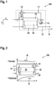
- a typical system topology of a fuel cell 100 is shown, which is designed with an anode chamber 10 for providing a fuel-containing gas mixture, a cathode chamber 20 for providing an oxygen-containing gas mixture and a membrane 30 for transporting fuel ions from the anode chamber 10 to the cathode chamber 20.
- the oxygen-containing gas mixture for the cathode chamber 20 of the fuel cell 100 is usually sucked in in the form of simple ambient air from the environment of the fuel cell 100.
- the fuel-containing gas mixture e.g. hydrogen, is usually provided from a tank in the anode chamber 10 of the fuel cell 100.
- Corresponding lines 11, 21 are provided for the transport of the reactants to and from the respective chambers 10, 20.
- a recirculation pump 12 is also provided in the anode line 11, which sends an unused fuel-containing gas mixture back into the anode chamber 10.
- the cathode line 21 is usually open to the outside in order to discharge unused air from the cathode chamber 20.
- the anode is operated in parallel with the cathode.
- the air or the oxygen-containing gas mixture flows into the cathode chamber 20, exchanges water vapor with the anode chamber 10 via the membrane 30 and simultaneously transports the water produced in the flow direction R of the oxygen-containing gas mixture from the cathode chamber 20 and thus from the fuel cell 100.
- the humidity of the oxygen-containing gas mixture or the cathode air therefore increases from the inlet to the outlet.
- fresh fuel-containing gas mixture from the tank is mixed with a recirculated gas mixture before entering the anode chamber 10.
- An external humidifier is usually not used in the anode line 11.
- the fresh fuel-containing gas mixture is taken dry from the tank.
- the humidity of the fuel-containing gas mixture before entering the anode chamber 10 therefore depends on the amount of humidity that is recirculated from the anode outlet to the anode inlet.
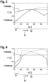
- the Figure 2 shows the anode in countercurrent operation to the cathode. This promotes an internal water circulation, as shown by the curved arrows. This water circulation increases the circulating water quantity and enables the operation of the fuel cell 100 even at operating temperatures above 60 °C without an external humidifier.
- the relative humidity curves ⁇ are also shown above for the anode chamber 10 (see ⁇ anode ) and below for the cathode chamber 20 (see ⁇ cathode ). The air flows dry into the cathode chamber 20 without an external humidifier. Its humidity generally increases due to the absorption of the product water.
- the partial pressure gradient of the water vapor between the The difference between the anode chamber 10 and the cathode chamber 20 is greatest.
- the cathode air removes water from the anode chamber 10 at this point, which cannot be circulated in the system and is therefore not available to humidify the anode inlet.
- the water balance of the fuel cell is balanced.
- Simulation models can be used to show that the coupling of the cathode and anode moisture profiles via the diffusion resistance of the membrane 30 has a major influence on the water balance of the fuel cell 100.
- the water permeability is directly dependent on the diffusion resistance of the water molecules through the membrane 30 and on the membrane thickness d.
- the cathode air or the oxygen-containing gas mixture flows through the cathode in the positive x-direction.
- the coolant temperature also increases.
- the compressed cathode air enters the cathode chamber 20 heated and unhumidified without an external humidifier and quickly absorbs water from the anode chamber 10.
- the gradient of the increase in humidity in the cathode air is steepest at the cathode inlet. This gradient decreases further in the direction of the cathode outlet because the difference in vapor partial pressure to the anode chamber 10 becomes smaller and smaller.
- liquid water can escape.
- the fuel-containing gas mixture or the anode gas mixture flows through the anode chamber 10 in the negative x-direction.
- the moisture in the anode chamber 10 increases very quickly again in between.
- the moisture profile in the anode is on average at a higher level in the second case than in the first case, but at the expense of the homogeneity of the moisture.
- the latter has a negative effect on a homogeneous current density distribution in the fuel cell 100 and thus also a negative effect on the highest possible power density.
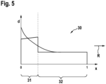
- the invention proposes to reduce the water transfer at the anode outlet (here, for example, between "0 ⁇ x ⁇ 0.1") by low water permeability of the membrane 30, as can be seen, for example, from the Figure 5
- the anode releases less water to the cathode in the cathode inlet area and more water can be recirculated in the anode path.
- This in turn helps to increase the inlet humidity of the anode gas mixture between 0.9 ⁇ x ⁇ 1.
- the ion conductivity remains independent of the graduated water permeability and is preferably sufficiently high everywhere over the entire surface of the membrane 30 in order to enable the fuel ions to pass through the membrane 30 with as little resistance as possible.
- the membrane 30 can also be provided with a graded ion conductivity in order to ensure a uniform ion conductivity over the entire length of the membrane 30.
- a graded water permeability can also be achieved by a graded thickness d of the membrane 30 in the flow direction R of the oxygen-containing gas mixture, for example with the same chemical membrane structure.
- the thickness d of the membrane 30 has a direct influence on the diffusion resistance for water molecules.
- the invention provides that the membrane thickness d is increased by at least 20%, for example by 50% up to 200% compared to the rest of the area of the fuel cell 100. Ideally, the increase is continuous.
- the partial change in thickness can be achieved by placing several layers or plies of the membrane 30 with a constant thickness d on top of one another. It is also conceivable that the layers placed on top of one another
- Membrane layers can also be joined together, e.g. by hot pressing.
Landscapes
- Chemical & Material Sciences (AREA)
- Life Sciences & Earth Sciences (AREA)
- Engineering & Computer Science (AREA)
- Manufacturing & Machinery (AREA)
- Sustainable Development (AREA)
- Sustainable Energy (AREA)
- Chemical Kinetics & Catalysis (AREA)
- Electrochemistry (AREA)
- General Chemical & Material Sciences (AREA)
- Composite Materials (AREA)
- Fuel Cell (AREA)
Description
- Die vorliegende Erfindung betrifft eine Brennstoffzelle nach dem Oberbegriff des unabhängigen Vorrichtungsanspruchs.
- Brennstoffzellen, bspw. PEM-Brennstoffzellen, stellen eine attraktive Technologie für eine CO2-freie Energiewirtschaft dar. Brennstoffzellen weisen eine Membran auf, die protonenleitend ist. Die Protonenleitfähigkeit der Membran hängt jedoch stark von der Membranfeuchte ab. Eine möglichst hohe Membranfeuchte ist daher für einen stabilen Betrieb der Brennstoffzelle unabdingbar. Allerdings wandern durch den elektroosmotischen Drag neben den Protonen auch Wassermoleküle von der Anode zur Kathode. Gleichzeitig hängt der ohmsche Widerstand der Brennstoffzelle von der Membrandicke ab. Innerhalb der letzten Dekade hat sich die Membrandicke von ca. 100 - 200 µm auf 10 µm verringert. Eine weitere Reduzierung der Membrandicke ist zu erwarten. Mit sinkender Membrandicke steigt auch die Wasserpermeabilität der Membran, was den Effekt der Entfeuchtung der Anode nachteilig begünstigt. Außerdem werden die Brennstoffzellen zumeist überstöchiometrisch betrieben, wobei das sauerstoffhaltige Gasgemisch verdichtet und dabei erwärmt wird, was ebenfalls zur Entfeuchtung der Membran beiträgt. Bekannte Maßnahmen gegen die Entfeuchtung der Membran sind Rezirkulation des Anodengasgemisches und Befeuchtung der Kathodenzuluft mit einem externen Befeuchter.
- Die Schrift
JP 2003 173798 A - Die Offenlegungsschrift
EP 2 701 226 A1 offenbart eine Brennstoffzelle mit einer Membran, wobei diese eine wechselnde Zusammensetzung über Ihre Länge aufweist. - Die Schrift
JP 2007 123122 A - Die vorliegende Erfindung sieht eine Brennstoffzelle mit den Merkmalen des unabhängigen Vorrichtungsanspruches, insbesondere aus dem kennzeichnenden Teil, vor. Weitere Vorteile, Merkmale und Details der Erfindung ergeben sich aus den jeweiligen Unteransprüchen, der Beschreibung und den Zeichnungen. Dabei können Merkmale und Details, die im Zusammenhang mit den einzelnen Ausführungsformen der Erfindung beschrieben sind, selbstverständlich kombiniert werden, sodass bezüglich der Offenbarung zu den einzelnen Erfindungsaspekten stets wechselseitig Bezug genommen wird bzw. werden kann.
- Die Erfindung stellt eine Brennstoffzelle bereit, die mit einem Anodenraum zum Bereitstellen eines brennstoffhaltigen Gasgemisches, einem Kathodenraum zum Bereitstellen eines sauerstoffhaltigen Gasgemisches und einer Membran zum Transportieren von Brennstoffionen aus dem Anodenraum zum Kathodenraum ausgebildet ist. Hierzu ist vorgesehen, dass die Membran mit einer gradierten Wasserpermeabilität ausgebildet ist.
- Unter "gradierten Wasserpermeabilität" im Sinne der Erfindung wird eine monoton (z. B. steigend oder fallend ausgestaltete) d.h. nicht periodisch veränderliche Wasserpermeabilität verstanden. Die Brennstoffzelle im Sinne der Erfindung kann in einem Stapel mit anderen gleichwertigen Brennstoffzellen zu einem Brennstoffzellensystem, einem sog. Stack zusammengefügt werden. Ein so gebildetes Brennstoffzellensystem kann in mobilen Anwendungen, bspw. bei Kraftfahrzeugen, und in stationären Anwendungen, bspw. als Generator, eingesetzt werden.
- Der Erfindungsgedanke liegt in der Verwendung einer Membran, die über der Fläche einen Gradienten der Permeabilität für Wasser aufweist, z. B: eine Membran mit einer gradierten, insbesondere in Flussrichtung des sauerstoffhaltigen Gasgemisches abfallenden, Dicke bzw. Materialstärke oder einer entsprechenden variablen chemischen Zusammensetzung. Durch eine gradierte Wasserpermeabilität der Membran kann ein optimaler Kompromiss aus niedriger mittlerer Membrandicke für niedrige ohmsche Verluste und ausreichend großer Membrandicke am Kathodeneintritt bzw. Anodenaustritt (insbesondere über die geometrische Erstreckung) eingestellt werden. Der Vorteil der Erfindung liegt in einem stabilen Wassermanagement bzw. einer stabilen Wasserbilanz der Brennstoffzelle im Betrieb. Damit sind auch dauerhaft hohe Brennstoffzellenleistungen möglich und die Fortschritte bei der Membrantechnologie (Dickenreduzierung) im realen Betrieb umsetzbar. Zusammenfassend lässt sich feststellen, dass eine Membran mit einer gradierten Wasserpermeabilität eine verbesserte Befeuchtung der Brennstoffzellenanode bzw. des Anodenraums auch bei der Verwendung von sehr dünnen Membranen sicherstellt.
- Ferner sieht die Erfindung bei einer Brennstoffzelle vorsehen, dass die Membran in Flussrichtung des sauerstoffhaltigen Gasgemisches gesehen einen Eingangsbereich und einen Betriebsbereich aufweist, wobei im Eingangsbereich zumindest zum Teil eine niedrigere Wasserpermeabilität eingestellt ist als im Betriebsbereich. In Flussrichtung des sauerstoffhaltigen Gasgemisches herrschen am Eingangsbereich der Brennstoffzellenkathode bzw. des Kathodenraumes hohe Temperaturen, die zu einem trockenen Gasgemisch führen können. Die Konzentration des Produktwassers im sauerstoffhaltigen Gasgemisch steigt erst im Laufe des Gasgemisches durch den Kathodenraum. Trockene Luft am Eingang in die Brennstoffzelle kann nachteilig Wasser aus dem Anodenraum entziehen. Gerade im Eingangsbereich ist es daher vorteilhaft, die Wasserpermeabilität zu reduzieren, um eine Diffusion des Wassers aus dem Anodenraum in den Kathodenraum zu verhindern.
- Erfindungsgemäß beträgt der Eingangsbereich der Membran in Flussrichtung des sauerstoffhaltigen Gasgemisches gesehen zwischen 1% und 20%, vorzugsweise 1% bis 10%, der Gesamtlänge der Membran beträgt. Überraschenderweise hat die Erfindung erkannt, dass ein sehr schmaler Eingangsbereich mit einer reduzierten Wasserpermeabilität bereits ausreichen kann, um effektiv und zuverlässig einer Austrocknung der Membran auf der Anodenseite zu verhindern, denn dieser Effekt am Eingang in den Kathodenraum am stärksten ist. Vorteilhafterweise kann bereits ein Bereich bis 20% und bei dickeren Membranen sogar bis 10% zuverlässig ein Übergang des Wassers aus dem Anodenraum in den Kathodenraum verhindern. Die Membran müsste daher nur in dem schmalen Eingangsbereich behandelt oder verdickt werden, um eine gleichmäßige Befeuchtung der Membran über die gesamte Länge zu erzielen.
- Des Weiteren ist es im Rahmen der Erfindung denkbar, dass die Wasserpermeabilität der Membran in Flussrichtung des sauerstoffhaltigen Gasgemisches gesehen von einem Eingangsbereich zu einem Betriebsbereich monoton oder stufenweise ansteigt. Je nach Herstellungsmethode kann es von Vorteil sein, entweder einer monotone oder eine stufenweise ansteigende Wasserpermeabilität der Membran bereitzustellen. So kann bei einer chemischen Zusammensetzung eine stufenweise Einstellung der Wasserpermeabilität, bspw. durch eine Dotierung, vorteilhaft sein, wohingegen bei einer Schichtbildung eine stufenweise Wasserpermeabilität der Membran von Vorteil sein kann.
- Außerdem kann die Erfindung bei einer Brennstoffzelle vorsehen, dass die gradierte Wasserpermeabilität durch eine wechselnde chemische Zusammensetzung der Membran oder durch eine Strukturierung oder Beschichtung mindestens einer Oberfläche der Membran, insbesondere bei einer konstanten Dicke der Membran, bereitgestellt ist. Mithilfe von chemischen Zusätzen oder bestimmten Strukturierungen oder Beschichtungen der Membran kann die Wasserpermeabilität beeinflusst werden. Wenn dabei die Dicke der Membran konstant verbleibt, dann wird der Zusammenbau der Brennstoffzelle durch die gradierte Wasserpermeabilität keinerlei beeinflusst.
- Zudem kann bei einer Brennstoffzelle im Sinne der Erfindung vorteilhaft sein, wenn die gradierte Wasserpermeabilität durch eine Änderung der Dicke der Membran, insbesondere bei einer konstanten chemischen Zusammensetzung der Membran, bereitgestellt ist. Somit kann auf eine einfache Weise und kostengünstig die erfindungsgemäße gradierte Wasserpermeabilität realisiert werden.
- Ferner kann die Erfindung vorsehen, dass eine Änderung der Dicke der Membran durch eine Schichtbildung hergestellt ist. Mithin kann nicht nur eine einfache, sondern auch eine präzise einstellbare Wasserpermeabilität realisiert werden.
- Weiterhin ist es im Rahmen der Erfindung denkbar, dass bei einer Schichtbildung der Membran mehrere Schichten der Membran stoffschlüssig miteinander verbunden sind. Dadurch kann der Vorteil erreicht werden, dass lonenleitfähigkeit der Membran durch die Schichten, ohne Unterbrechung, gewährleistet wird.
- Des Weiteren kann die Erfindung vorsehen, dass in die Flussrichtung des sauerstoffhaltigen Gasgemisches gesehen zumindest in einem Eingangsbereich der Membran die Dicke der Membran 20% bis 200%, vorzugsweise 50% bis 200% der Normaldicke der Membran in einem Betriebsbereich beträgt. Mit anderen Worten kann im Eingangsbereich der Membran eine Dicke vorzugsweise bei zum einer doppelten Normaldicke der Membran eingestellt werden. Dadurch kann auf eine einfache Weise zuverlässig ermöglicht werden, dass die Wassermoleküle im Eingangsbereich der Membran nicht aus dem Anodenraum in den Kathodenbereich übergehen.
- Außerdem ist es im Rahmen der Erfindung denkbar, dass die lonenleitfähigkeit der Membran an eine Änderung der Wasserpermeabilität der Membran angepasst ist, um einen gleichmäßigen Diffusionswiderstand für die Brennstoffionen durch die Membran über die Gesamtlänge der Membran zu ermöglichen. Dies kann vorteilhafterweise eine gleichmäßige lonenleitfähigkeit über die gesamte Gesamtlänge der Membran sicherstellen.
- Die erfindungsgemäße Brennstoffzelle und ihre Weiterbildungen sowie deren Vorteile werden nachfolgend anhand von Zeichnungen näher erläutert. Es zeigen jeweils schematisch:
- Fig. 1
- ein schematischer Aufbau einer Brennstoffzelle mit Anodenrezirkulation,
- Fig. 2
- eine schematische Darstellung eines Feuchteverlaufes innerhalb einer Brennstoffzelle,
- Fig. 3
- eine schematische Darstellung eines Feuchteverlaufes innerhalb einer Brennstoffzelle mit einer bestimmten Membrandicke,
- Fig. 4
- eine schematische Darstellung eines Feuchteverlaufes innerhalb einer Brennstoffzelle mit einer in etwa fünffach kleineren Membrandicke als die Membrandicke gemäß der
Figur 3 , und - Fig. 5
- einen schematischen Aufbau einer erfindungsgemäßen Membran.
- In den unterschiedlichen Figuren sind gleiche Teile der Brennstoffzelle 100 stets mit denselben Bezugszeichen versehen, weshalb diese in der Regel nur einmal beschrieben werden.
- In der
Figur 1 ist eine typische Systemtopologie einer Brennstoffzelle 100 abgebildet, die mit einem Anodenraum 10 zum Bereitstellen eines brennstoffhaltigen Gasgemisches, einem Kathodenraum 20 zum Bereitstellen eines sauerstoffhaltigen Gasgemisches und einer Membran 30 zum Transportieren von Brennstoffionen aus dem Anodenraum 10 zum Kathodenraum 20 ausgeführt ist. Das sauerstoffhaltige Gasgemisch für den Kathodenraum 20 der Brennstoffzelle 100 wird zumeist in Form von einfacher Umgebungsluft aus der Umgebung der Brennstoffzelle 100 angesaugt. Das brennstoffhaltige Gasgemisch, bspw. Wasserstoff, wird meistens aus einem Tank in den Anodenraum 10 der Brennstoffzelle 100 bereitgestellt. Für den Transport der Reaktanten zum und vom dem jeweiligen Raum 10, 20 sind entsprechende Leitungen 11, 21 vorgesehen. In der Anodenleitung 11 ist zudem eine Rezirkulationspumpe 12 vorgesehen, die ein unverbrauchtes brennstoffhaltiges Gasgemisch zurück in den Anodenraum 10 schickt. Die Kathodenleitung 21 ist meistens nach außen offen, um unverbrauchte Luft aus dem Kathodenraum 20 abzulassen. - Im Beispiel der
Figur 1 wird die Anode im Gleichstrom mit der Kathode betrieben. Die Luft bzw. das sauerstoffhaltige Gasgemisch strömt in den Kathodenraum 20 ein, tauscht Wasserdampf über die Membran 30 mit dem Anodenraum 10 aus und transportiert gleichzeitig das produzierte Wasser in Flussrichtung R des sauerstoffhaltigen Gasgemisches aus dem Kathodenraum 20 und somit aus der Brennstoffzelle 100 ab. Die Feuchte des sauerstoffhaltigen Gasgemisches bzw. der Kathodenluft nimmt also vom Eintritt- zum Austritt zu. In der Anodenleitung 11 wird frisches brennstoffhaltiges Gasgemisch aus dem Tank mit einem rezirkulierten Gasgemisch vor dem Eintritt in den Anodenraum 10 vermischt. In der Anodenleitung 11 wird üblicherweise kein externer Befeuchter verwendet. Das frische brennstoffhaltige Gasgemisch wird trocken aus dem Tank entnommen. Die Feuchte des brennstoffhaltigen Gasgemisches vor dem Eintritt in den Anodenraum 10 hängt daher von der Feuchtemenge ab, die vom Anodenausgang aus zum Anodeneingang rezirkuliert wird. Je dünner die Membran 30 ist, desto kleiner ist der Diffusionswiderstand für Wasser. Dies führt zu einem verstärkten Austausch von Wasser zwischen dem Kathodenraum 20 und dem Anodenraum 10 der Brennstoffzelle 100. - Die
Figur 2 zeigt die Anode im Gegenstrombetrieb zur Kathode. Dadurch wird eine innere Wasserzirkulation, wie mit den gebogenen Pfeilen gezeigt ist, gefördert. Diese Wasserzirkulation erhöht die umlaufende Wassermenge und ermöglicht den Betrieb der Brennstoffzelle 100 auch bei Betriebstemperaturen über 60 °C ohne externen Befeuchter. Zusätzlich zu den Strömungsrichtungen sind auch die Verläufe der relativen Feuchte ϕ oben für den Anodenraum 10 (s. ϕAnode) und unten für den Kathodenraum 20 (s. ϕKathode) dargestellt. Die Luft strömt ohne externen Befeuchter trocken in den Kathodenraum 20 ein. Ihre Feuchte steigt durch die Aufnahme des Produktwassers generell an. Am Eintritt in den Kathodenraum 20 ist das Partialdruckgefälle des Wasserdampfes zwischen dem Anodenraum 10 und dem Kathodenraum 20 am größten. Dadurch entzieht die Kathodenluft dem Anodenraum 10 an dieser Stelle Wasser, welches im System nicht zirkuliert werden kann und damit auch nicht zur Befeuchtung des Anodeneintritts zur Verfügung steht. Im stationären Zustand stellt sich ein ausgeglichener Wasserhaushalt der Brennstoffzelle ein. - Mit Simulationsmodellen kann gezeigt werden, dass die Kopplung der Kathoden- und Anodenfeuchteverläufe über den Diffusionswiderstand der Membran 30 großen Einfluss auf den Wasserhaushalt der Brennstoffzelle 100 hat. Die Wasserdurchlässigkeit/Permeabilität ist direkt abhängig vom Diffusionswiderstand der Wassermoleküle durch die Membran 30 und von der Membrandicke d.
- In den
Figuren 3 und 4 wird der Wasserhaushalt von zwei Szenarien gezeigt. Im ersten Fall derFigur 3 liegt der Diffusionswiderstand der Membran 30 bei einem bestimmten Wert, der einer bestimmten Membrandicke d entspricht. Im zweiten Fall derFigur 4 wird mit einem, bspw. um den Faktor 5 kleiner gewählten, Diffusionswiderstand für Wassermoleküle durch die Membran 30 simuliert. Die große Reduzierung des Diffusionswiderstands hilft den Effekt der Entfeuchtung der Membran auf der Anodenseite zu veranschaulichen. In der Realität wird die Reduzierung des Diffusionswiderstands ggf. kleiner ausfallen, jedoch dennoch relevant für den Wasserhaushalt innerhalb der Brennstoffzelle 100 sein. - In der Ansicht der
Figur 3 ist erkennbar, dass die Kathodenluft bzw. das sauerstoffhaltige Gasgemisch die Kathode in positiver x-Richtung durchströmt. "x=0" entspricht dabei dem Kathodeneintritt und "x=1" - dem Kathodenaustritt, was in der Ansicht derFigur 3 einer Richtung von links nach rechts und gleichzeitig der Flussrichtung R des sauerstoffhaltigen Gasgemisches durch den Kathodenraum 20 entspricht. In dieser Flussrichtung R nimmt auch die Kühlmitteltemperatur zu. Die verdichtete Kathodenluft gelangt erhitzt und ohne externen Befeuchter unbefeuchtet in den Kathodenraum 20 und nimmt schnell Wasser aus dem Anodenraum 10 auf. Am Kathodeneintritt ist der Gradient der Feuchtezunahme in der Kathodenluft am steilsten. Dieser Gradient nimmt in Richtung des Kathodenaustritts immer weiter ab, weil die Dampfpartialdruckdifferenz zum Anodenraum 10 immer kleiner wird. Bei Feuchten über "1" kann flüssiges Wasser austreten. Das brennstoffhaltige Gasgemisch bzw. das Anodengasgemisch durchströmt den Anodenraum 10 in negativer x-Richtung. "x=1" entspricht dabei dem Anodeneintritt und "x=0" - dem Anodenaustritt, was in der Ansicht derFigur 3 der Richtung von rechts nach links entspricht. Zunächst sinkt die relative Feuchte des Anodengasgemisches durch die Erwärmung auf die Stacktemperatur im Bereich von "x=1" ab. Danach steigt die Feuchte auf ein Maximum bei ungefähr "x=0,45" an und sinkt danach wieder ab, weil Wasserdampf in Richtung des sehr trockenen Kathodeneintritts diffundiert. - Im zweiten Fall gemäß der
Figur 4 mit signifikant niedrigerem Diffusionswiderstand der Membran 30, bspw. mit einer deutlich kleineren Dicke d als die Membrandicke d gemäß derFigur 3 , treten dieselben Effekte auf. Diese wirken jedoch deutlich stärker, wie es aus derFigur 4 ersichtlich ist. Bei "x=0" ist der Gradient der Feuchtezunahme in dem Kathodenraum 20 viel steiler ausgeprägt als im ersten Fall. Dies hat zur Folge, dass der Anodenraum 10, welcher weiterhin im Gegenstrom mit dem brennstoffhaltigen Gasgemisch betrieben wird, weniger Feuchte aufweist als im ersten Fall. Damit hat auch das Anodenrezirkulat einen geringeren Feuchtegehalt, was sich bei "x=1" am Anodeneintritt bemerkbar macht. Auch dort ist der Anodenraum 10 sehr trocken. Durch den geringen Diffusionswiderstand steigt die Feuchte im Anodenraum 10 dazwischen wieder sehr schnell an. Der Feuchteverlauf in der Anode ist im zweiten Fall im Mittel auf einem höheren Niveau als im ersten Fall, jedoch auf Kosten der Homogenität der Feuchte. Letzteres wirkt sich negativ auf eine homogene Stromdichteverteilung in der Brennstoffzelle 100 und damit auch negativ auf eine möglichst hohe Leistungsdichte aus. - Zur Wiederherstellung der Homogenität der Befeuchtung innerhalb der Brennstoffzelle 10 schlägt die Erfindung vor, den Wasserübertritt am Anodenaustritt (hier z.B. zwischen "0<x<0,1") durch niedrige Wasserpermeabilität der Membran 30 zu verringern, wie dies bspw. anhand der
Figur 5 dargestellt ist. Dadurch gibt die Anode weniger Wasser an die Kathode im Kathodeneintrittsbereich ab und es kann mehr Wasser im Anodenpfad rezirkuliert werden. Dies hilft wiederum die Eintrittsfeuchte des Anodengasgemisches zwischen 0,9 <x<1 zu erhöhen. - Im Sinne der Erfindung kann eine gradierte Wasserpermeabilität durch folgende Varianten umgesetzt werden:
- i) Die Membran 30 kann so ausgeprägt werden, dass die Permeabilität in Flussrichtung R des sauerstoffhaltigen Gasgemisches gradiert ist. Dies könnte zum Beispiel durch eine wechselnde chemische Zusammensetzung der Membran 30 erreicht werden, die den Diffusionswiderstand für Wasser gradiert. Weiterhin ist es denkbar, dass die Membran 30 an einer oder beiden Oberflächen so gestaltet werden kann, bspw. mithilfe einer Strukturierung oder (z. B. wasserundurchlässigen) Beschichtung, dass die Adsorptions-/Desorptionseigenschaften über der Länge der Membran 30 variieren.
- Ferner kann im Rahmen der Erfindung eingestellt werden, dass die lonenleitfähigkeit von der graduierten Wasserpermeabilität unabhängig bleibt und vorzugsweise überall auf der Gesamtfläche der Membran 30 ausreichend hoch ist, um einen möglichst widerstandsfreien Übergang der Brennstoffionen durch die Membran 30 zu ermöglichen.
- Des Weiteren kann jedoch die Membran 30 mit einer ebenfalls gradierten lonenleitfähigkeit bereitgestellt werden, um eine gleichmäßige lonenleitfähigkeit über die Gesamtlänge der Membran 30 sicherzustellen.
- ii) Eine gradierte Wasserpermeabilität kann weiterhin durch eine gradierte Dicke d der Membran 30 in Flussrichtung R des sauerstoffhaltigen Gasgemisches, bspw. bei gleichem chemischem Membranaufbau, realisiert werden. Die Dicke d der Membran 30 hat einen direkten Einfluss auf den Diffusionswiderstand für Wassermoleküle. Im Bereich von "0<x<0,2", zumindest jedoch "0<x<0,1", sieht die Erfindung vor, dass die Membrandicke d um mindestens 20%, bspw. um 50 % bis zu 200% gegenüber dem restlichen Bereich der Brennstoffzelle 100 erhöht wird. Idealerweise erfolgt die Erhöhung stufenlos. Gleichwohl ist es aber auch denkbar, sodass die partielle Dickenänderung durch Aufeinanderlegen von mehreren Schichten bzw. Lagen der Membran 30 mit konstanter Dicke d erfolgen kann. Weiterhin ist es denkbar, dass die aufeinandergelegten
- Membranenschichten zusätzlich miteinander gefügt werden können, z.B. durch Heißverpressen.
- Die voranstehende Beschreibung der Figuren beschreibt die vorliegende Erfindung ausschließlich im Rahmen von Beispielen. Selbstverständlich können einzelne Merkmale der Ausführungsformen, sofern es technisch sinnvoll ist, frei miteinander kombiniert werden, ohne den Rahmen der Erfindung zu verlassen.
Claims (8)
- Brennstoffzelle (100) miteinem Anodenraum (10) zum Bereitstellen eines brennstoffhaltigen Gasgemisches, einem Kathodenraum (20) zum Bereitstellen eines sauerstoffhaltigen Gasgemisches und einer Membran (30) zum Transportieren von Brennstoffionen aus dem Anodenraum (10) zum Kathodenraum (20), wobeidie Membran (30) mit einer gradierten Wasserpermeabilität ausgebildet ist; wobeidie Membran (30) in Flussrichtung (R) des sauerstoffhaltigen Gasgemisches gesehen einen Eingangsbereich (31) und einen Betriebsbereich (32) aufweist, wobei im Eingangsbereich (31) zumindest zum Teil eine niedrigere Wasserpermeabilität eingestellt ist als im Betriebsbereich (32),dadurch gekennzeichnet, dass der Eingangsbereich (31) der Membran in Flussrichtung (R) des sauerstoffhaltigen Gasgemisches gesehen zwischen 1% und 20%, vorzugsweise 1% bis 10%, der Gesamtlänge der Membran (30) beträgt.
- Brennstoffzelle (10) nach Anspruch 1,
dadurch gekennzeichnet,
dass die Wasserpermeabilität der Membran (30) in Flussrichtung (R) des sauerstoffhaltigen Gasgemisches gesehen von einem Eingangsbereich (31) zu einem Betriebsbereich (32) monoton oder stufenweise ansteigt. - Brennstoffzelle (10) nach einem der vorhergehenden Ansprüche,
dadurch gekennzeichnet,
dass die gradierte Wasserpermeabilität durch eine wechselnde chemische Zusammensetzung der Membran (30) oder durch eine Strukturierung oder Beschichtung mindestens einer Oberfläche der Membran (30), insbesondere bei einer konstanten Dicke (d) der Membran (30), bereitgestellt ist. - Brennstoffzelle (10) nach einem der vorhergehenden Ansprüche,
dadurch gekennzeichnet,
dass die gradierte Wasserpermeabilität durch eine Änderung der Dicke (d) der Membran (30), insbesondere bei einer konstanten chemischen Zusammensetzung der Membran (30), bereitgestellt ist. - Brennstoffzelle (10) nach einem der vorhergehenden Ansprüche,
dadurch gekennzeichnet,
dass eine Änderung der Dicke (d) der Membran (30) durch eine Schichtbildung hergestellt ist. - Brennstoffzelle (10) nach dem vorhergehenden Anspruch,
dadurch gekennzeichnet,
dass bei einer Schichtbildung der Membran (30) mehrere Schichten der Membran (30) stoffschlüssig miteinander verbunden sind. - Brennstoffzelle (10) nach einem der vorhergehenden Ansprüche,
dadurch gekennzeichnet,
dass in die Flussrichtung (R) des sauerstoffhaltigen Gasgemisches gesehen zumindest in einem Eingangsbereich (31) der Membran (30) die Dicke (d) der Membran (30) 20% bis 200%, vorzugsweise 50% bis 200% der Membran (30) in einem Betriebsbereich (32) beträgt. - Brennstoffzelle (10) nach einem der vorhergehenden Ansprüche,
dadurch gekennzeichnet,
dass die lonenleitfähigkeit der Membran (30) an eine Änderung der Wasserpermeabilität der Membran (30) angepasst ist, um einen gleichmäßigen Diffusionswiedertand für die Brennstoffionen durch die Membran (30) über die Gesamtlänge der Membran (30) zu ermöglichen.
Applications Claiming Priority (2)
| Application Number | Priority Date | Filing Date | Title |
|---|---|---|---|
| DE102017220669.1A DE102017220669A1 (de) | 2017-11-20 | 2017-11-20 | Brennstoffzelle mit variabler Wasserpermeabilität |
| PCT/EP2018/078024 WO2019096512A1 (de) | 2017-11-20 | 2018-10-15 | Brennstoffzelle mit variabler wasserpermeabilität |
Publications (2)
| Publication Number | Publication Date |
|---|---|
| EP3714504A1 EP3714504A1 (de) | 2020-09-30 |
| EP3714504B1 true EP3714504B1 (de) | 2024-08-21 |
Family
ID=63915009
Family Applications (1)
| Application Number | Title | Priority Date | Filing Date |
|---|---|---|---|
| EP18789352.4A Active EP3714504B1 (de) | 2017-11-20 | 2018-10-15 | Brennstoffzelle mit variabler wasserpermeabilität |
Country Status (7)
| Country | Link |
|---|---|
| US (1) | US11289720B2 (de) |
| EP (1) | EP3714504B1 (de) |
| JP (1) | JP7184493B2 (de) |
| KR (1) | KR102705882B1 (de) |
| CN (1) | CN111373585B (de) |
| DE (1) | DE102017220669A1 (de) |
| WO (1) | WO2019096512A1 (de) |
Family Cites Families (10)
| Publication number | Priority date | Publication date | Assignee | Title |
|---|---|---|---|---|
| DE19709199A1 (de) * | 1997-03-06 | 1998-09-17 | Magnet Motor Gmbh | Gasdiffusionselektrode mit verringertem Diffusionsvermögen für Wasser und Verfahren zum Betreiben einer Polymerelektrolytmembran-Brennstoffzelle ohne Zuführung von Membranbefeuchtungswasser |
| JP4610815B2 (ja) * | 2001-09-14 | 2011-01-12 | 東芝燃料電池システム株式会社 | 固体高分子形燃料電池 |
| JP4032282B2 (ja) | 2001-12-06 | 2008-01-16 | トヨタ自動車株式会社 | 固体高分子電解質膜型燃料電池 |
| US7374838B2 (en) * | 2003-06-10 | 2008-05-20 | Ballard Power Systems Inc. | Electrochemical fuel cell with fluid distribution layer having non-uniform permeability |
| JP2006147425A (ja) | 2004-11-22 | 2006-06-08 | Nissan Motor Co Ltd | 固体高分子型燃料電池用電解質膜およびその製造方法並びに固体高分子型燃料電池 |
| JP5157047B2 (ja) | 2005-07-06 | 2013-03-06 | トヨタ自動車株式会社 | 固体高分子電解質型燃料電池で用いる電解質膜の製造方法 |
| JP5002939B2 (ja) * | 2005-10-28 | 2012-08-15 | 日産自動車株式会社 | 燃料電池用電解質膜および膜電極接合体 |
| US20080241606A1 (en) * | 2007-03-30 | 2008-10-02 | Gallagher Emerson R | Method and apparatus for humidifying a gas in fuel cell systems |
| JP5210096B2 (ja) * | 2008-09-09 | 2013-06-12 | パナソニック株式会社 | 直接酸化型燃料電池 |
| US10256494B2 (en) | 2011-08-09 | 2019-04-09 | Panasonic Intellectual Property Management Co. Ltd. | Electrolyte membrane for solid polymer fuel cell, method for manufacturing same, and solid polymer fuel cell |
-
2017
- 2017-11-20 DE DE102017220669.1A patent/DE102017220669A1/de not_active Withdrawn
-
2018
- 2018-10-15 JP JP2020523391A patent/JP7184493B2/ja active Active
- 2018-10-15 US US16/765,520 patent/US11289720B2/en active Active
- 2018-10-15 KR KR1020207017602A patent/KR102705882B1/ko active Active
- 2018-10-15 WO PCT/EP2018/078024 patent/WO2019096512A1/de not_active Ceased
- 2018-10-15 CN CN201880075125.7A patent/CN111373585B/zh active Active
- 2018-10-15 EP EP18789352.4A patent/EP3714504B1/de active Active
Also Published As
| Publication number | Publication date |
|---|---|
| KR20200090203A (ko) | 2020-07-28 |
| US11289720B2 (en) | 2022-03-29 |
| DE102017220669A1 (de) | 2019-05-23 |
| CN111373585B (zh) | 2023-07-14 |
| US20200321638A1 (en) | 2020-10-08 |
| WO2019096512A1 (de) | 2019-05-23 |
| JP2021500722A (ja) | 2021-01-07 |
| KR102705882B1 (ko) | 2024-09-12 |
| JP7184493B2 (ja) | 2022-12-06 |
| EP3714504A1 (de) | 2020-09-30 |
| CN111373585A (zh) | 2020-07-03 |
Similar Documents
| Publication | Publication Date | Title |
|---|---|---|
| DE112005001084B4 (de) | Gasseparator und Verfahren zu dessen Betrieb | |
| DE102008006735B4 (de) | Brennstoffzellensystem und dafür vorgesehene Wasserdampfübertragungseinheit | |
| DE69810841T2 (de) | Verfahren zum Betrieb einer Polymerelektrolyt-Brennstoffzelle mit innerer Befeuchtung | |
| DE112006000958B4 (de) | Brennstoffzelle | |
| DE102007026331A1 (de) | Systemniveaueinstellungen zur Erhöhung der Stapeleinlass-RF | |
| DE112008001766B4 (de) | Elektrolytmembran und Brennstoffzelle unter Verwendung derselben | |
| DE102012205643B4 (de) | Brennstoffzellensystem und Verfahren zum Stoppen der Stromerzeugung in einem Brennstoffzellensystem | |
| DE112008000960T5 (de) | Brennstoffzellensystem und Verfahren zum Steuern des Brennstoffzellensystems | |
| DE102010017397A1 (de) | Membranelektrodenanordnung und Brennstoffzelle | |
| DE102019103818A1 (de) | Verfahren zur Herstellung einer integrierten Wasserdampfübertragungsvorrichtung und Brennstoffzelle - II | |
| DE102014224135A1 (de) | Verfahren zum Abschalten eines Brennstoffzellenstapels sowie Brennstoffzellensystem | |
| DE112007000240T5 (de) | Brennstoffzellenstapel | |
| EP3714504B1 (de) | Brennstoffzelle mit variabler wasserpermeabilität | |
| DE102019126306A1 (de) | Brennstoffzellensystem | |
| DE112007002132B4 (de) | Brennstoffzelle mit Gasstrompfaden | |
| DE112010002746B4 (de) | Reaktionsschicht für Brennstoffzelle | |
| DE112005000646B4 (de) | Brennstoffzelle | |
| WO2007140849A1 (de) | Brennstoffzelle mit einer separatorplatteneinheit und separatorplatteneinheit | |
| DE102020207581A1 (de) | Separator für brennstoffzelle | |
| DE102007061128B4 (de) | Verfahren zur hydrophilen Behandlung für zusammengebaute PEMFC-Stapel und System zum Abscheiden eines hydrophilen Materials | |
| WO2019141429A1 (de) | Kaskadierter brennstoffzellenstapel mit optimiertem wassermanagement und brennstoffzellensystem | |
| EP2139061A1 (de) | Membranbefeuchterzelle und Brennstoffzelleneinrichtung dieselbe enthaltend | |
| DE102006001645A1 (de) | Steuerung von mit relativer Feuchte in Verbindung stehender Bedingungen in einer Anordnung für elektrochemische Umwandlung | |
| DE10324386B4 (de) | Brennstoffzellensystem | |
| DE102019205810A1 (de) | Befeuchter sowie Brennstoffzellenvorrichtung mit einem solchen |
Legal Events
| Date | Code | Title | Description |
|---|---|---|---|
| STAA | Information on the status of an ep patent application or granted ep patent |
Free format text: STATUS: UNKNOWN |
|
| STAA | Information on the status of an ep patent application or granted ep patent |
Free format text: STATUS: THE INTERNATIONAL PUBLICATION HAS BEEN MADE |
|
| PUAI | Public reference made under article 153(3) epc to a published international application that has entered the european phase |
Free format text: ORIGINAL CODE: 0009012 |
|
| STAA | Information on the status of an ep patent application or granted ep patent |
Free format text: STATUS: REQUEST FOR EXAMINATION WAS MADE |
|
| 17P | Request for examination filed |
Effective date: 20200622 |
|
| AK | Designated contracting states |
Kind code of ref document: A1 Designated state(s): AL AT BE BG CH CY CZ DE DK EE ES FI FR GB GR HR HU IE IS IT LI LT LU LV MC MK MT NL NO PL PT RO RS SE SI SK SM TR |
|
| AX | Request for extension of the european patent |
Extension state: BA ME |
|
| DAV | Request for validation of the european patent (deleted) | ||
| DAX | Request for extension of the european patent (deleted) | ||
| GRAP | Despatch of communication of intention to grant a patent |
Free format text: ORIGINAL CODE: EPIDOSNIGR1 |
|
| STAA | Information on the status of an ep patent application or granted ep patent |
Free format text: STATUS: GRANT OF PATENT IS INTENDED |
|
| INTG | Intention to grant announced |
Effective date: 20240314 |
|
| GRAS | Grant fee paid |
Free format text: ORIGINAL CODE: EPIDOSNIGR3 |
|
| GRAA | (expected) grant |
Free format text: ORIGINAL CODE: 0009210 |
|
| STAA | Information on the status of an ep patent application or granted ep patent |
Free format text: STATUS: THE PATENT HAS BEEN GRANTED |
|
| AK | Designated contracting states |
Kind code of ref document: B1 Designated state(s): AL AT BE BG CH CY CZ DE DK EE ES FI FR GB GR HR HU IE IS IT LI LT LU LV MC MK MT NL NO PL PT RO RS SE SI SK SM TR |
|
| REG | Reference to a national code |
Ref country code: GB Ref legal event code: FG4D Free format text: NOT ENGLISH |
|
| REG | Reference to a national code |
Ref country code: CH Ref legal event code: EP |
|
| REG | Reference to a national code |
Ref country code: IE Ref legal event code: FG4D Free format text: LANGUAGE OF EP DOCUMENT: GERMAN |
|
| REG | Reference to a national code |
Ref country code: DE Ref legal event code: R096 Ref document number: 502018015043 Country of ref document: DE |
|
| P01 | Opt-out of the competence of the unified patent court (upc) registered |
Free format text: CASE NUMBER: APP_55939/2024 Effective date: 20241011 |
|
| REG | Reference to a national code |
Ref country code: LT Ref legal event code: MG9D |
|
| REG | Reference to a national code |
Ref country code: NL Ref legal event code: MP Effective date: 20240821 |
|
| PG25 | Lapsed in a contracting state [announced via postgrant information from national office to epo] |
Ref country code: NO Free format text: LAPSE BECAUSE OF FAILURE TO SUBMIT A TRANSLATION OF THE DESCRIPTION OR TO PAY THE FEE WITHIN THE PRESCRIBED TIME-LIMIT Effective date: 20241121 |
|
| PG25 | Lapsed in a contracting state [announced via postgrant information from national office to epo] |
Ref country code: PT Free format text: LAPSE BECAUSE OF FAILURE TO SUBMIT A TRANSLATION OF THE DESCRIPTION OR TO PAY THE FEE WITHIN THE PRESCRIBED TIME-LIMIT Effective date: 20241223 Ref country code: NL Free format text: LAPSE BECAUSE OF FAILURE TO SUBMIT A TRANSLATION OF THE DESCRIPTION OR TO PAY THE FEE WITHIN THE PRESCRIBED TIME-LIMIT Effective date: 20240821 Ref country code: GR Free format text: LAPSE BECAUSE OF FAILURE TO SUBMIT A TRANSLATION OF THE DESCRIPTION OR TO PAY THE FEE WITHIN THE PRESCRIBED TIME-LIMIT Effective date: 20241122 Ref country code: FI Free format text: LAPSE BECAUSE OF FAILURE TO SUBMIT A TRANSLATION OF THE DESCRIPTION OR TO PAY THE FEE WITHIN THE PRESCRIBED TIME-LIMIT Effective date: 20240821 Ref country code: PL Free format text: LAPSE BECAUSE OF FAILURE TO SUBMIT A TRANSLATION OF THE DESCRIPTION OR TO PAY THE FEE WITHIN THE PRESCRIBED TIME-LIMIT Effective date: 20240821 |
|
| PG25 | Lapsed in a contracting state [announced via postgrant information from national office to epo] |
Ref country code: BG Free format text: LAPSE BECAUSE OF FAILURE TO SUBMIT A TRANSLATION OF THE DESCRIPTION OR TO PAY THE FEE WITHIN THE PRESCRIBED TIME-LIMIT Effective date: 20240821 |
|
| PG25 | Lapsed in a contracting state [announced via postgrant information from national office to epo] |
Ref country code: LV Free format text: LAPSE BECAUSE OF FAILURE TO SUBMIT A TRANSLATION OF THE DESCRIPTION OR TO PAY THE FEE WITHIN THE PRESCRIBED TIME-LIMIT Effective date: 20240821 |
|
| PG25 | Lapsed in a contracting state [announced via postgrant information from national office to epo] |
Ref country code: IS Free format text: LAPSE BECAUSE OF FAILURE TO SUBMIT A TRANSLATION OF THE DESCRIPTION OR TO PAY THE FEE WITHIN THE PRESCRIBED TIME-LIMIT Effective date: 20241221 |
|
| PG25 | Lapsed in a contracting state [announced via postgrant information from national office to epo] |
Ref country code: HR Free format text: LAPSE BECAUSE OF FAILURE TO SUBMIT A TRANSLATION OF THE DESCRIPTION OR TO PAY THE FEE WITHIN THE PRESCRIBED TIME-LIMIT Effective date: 20240821 |
|
| PG25 | Lapsed in a contracting state [announced via postgrant information from national office to epo] |
Ref country code: ES Free format text: LAPSE BECAUSE OF FAILURE TO SUBMIT A TRANSLATION OF THE DESCRIPTION OR TO PAY THE FEE WITHIN THE PRESCRIBED TIME-LIMIT Effective date: 20240821 Ref country code: RS Free format text: LAPSE BECAUSE OF FAILURE TO SUBMIT A TRANSLATION OF THE DESCRIPTION OR TO PAY THE FEE WITHIN THE PRESCRIBED TIME-LIMIT Effective date: 20241121 |
|
| PG25 | Lapsed in a contracting state [announced via postgrant information from national office to epo] |
Ref country code: RS Free format text: LAPSE BECAUSE OF FAILURE TO SUBMIT A TRANSLATION OF THE DESCRIPTION OR TO PAY THE FEE WITHIN THE PRESCRIBED TIME-LIMIT Effective date: 20241121 Ref country code: PT Free format text: LAPSE BECAUSE OF FAILURE TO SUBMIT A TRANSLATION OF THE DESCRIPTION OR TO PAY THE FEE WITHIN THE PRESCRIBED TIME-LIMIT Effective date: 20241223 Ref country code: PL Free format text: LAPSE BECAUSE OF FAILURE TO SUBMIT A TRANSLATION OF THE DESCRIPTION OR TO PAY THE FEE WITHIN THE PRESCRIBED TIME-LIMIT Effective date: 20240821 Ref country code: NO Free format text: LAPSE BECAUSE OF FAILURE TO SUBMIT A TRANSLATION OF THE DESCRIPTION OR TO PAY THE FEE WITHIN THE PRESCRIBED TIME-LIMIT Effective date: 20241121 Ref country code: NL Free format text: LAPSE BECAUSE OF FAILURE TO SUBMIT A TRANSLATION OF THE DESCRIPTION OR TO PAY THE FEE WITHIN THE PRESCRIBED TIME-LIMIT Effective date: 20240821 Ref country code: LV Free format text: LAPSE BECAUSE OF FAILURE TO SUBMIT A TRANSLATION OF THE DESCRIPTION OR TO PAY THE FEE WITHIN THE PRESCRIBED TIME-LIMIT Effective date: 20240821 Ref country code: IS Free format text: LAPSE BECAUSE OF FAILURE TO SUBMIT A TRANSLATION OF THE DESCRIPTION OR TO PAY THE FEE WITHIN THE PRESCRIBED TIME-LIMIT Effective date: 20241221 Ref country code: HR Free format text: LAPSE BECAUSE OF FAILURE TO SUBMIT A TRANSLATION OF THE DESCRIPTION OR TO PAY THE FEE WITHIN THE PRESCRIBED TIME-LIMIT Effective date: 20240821 Ref country code: GR Free format text: LAPSE BECAUSE OF FAILURE TO SUBMIT A TRANSLATION OF THE DESCRIPTION OR TO PAY THE FEE WITHIN THE PRESCRIBED TIME-LIMIT Effective date: 20241122 Ref country code: FI Free format text: LAPSE BECAUSE OF FAILURE TO SUBMIT A TRANSLATION OF THE DESCRIPTION OR TO PAY THE FEE WITHIN THE PRESCRIBED TIME-LIMIT Effective date: 20240821 Ref country code: ES Free format text: LAPSE BECAUSE OF FAILURE TO SUBMIT A TRANSLATION OF THE DESCRIPTION OR TO PAY THE FEE WITHIN THE PRESCRIBED TIME-LIMIT Effective date: 20240821 Ref country code: BG Free format text: LAPSE BECAUSE OF FAILURE TO SUBMIT A TRANSLATION OF THE DESCRIPTION OR TO PAY THE FEE WITHIN THE PRESCRIBED TIME-LIMIT Effective date: 20240821 |
|
| PG25 | Lapsed in a contracting state [announced via postgrant information from national office to epo] |
Ref country code: DK Free format text: LAPSE BECAUSE OF FAILURE TO SUBMIT A TRANSLATION OF THE DESCRIPTION OR TO PAY THE FEE WITHIN THE PRESCRIBED TIME-LIMIT Effective date: 20240821 Ref country code: SM Free format text: LAPSE BECAUSE OF FAILURE TO SUBMIT A TRANSLATION OF THE DESCRIPTION OR TO PAY THE FEE WITHIN THE PRESCRIBED TIME-LIMIT Effective date: 20240821 Ref country code: RO Free format text: LAPSE BECAUSE OF FAILURE TO SUBMIT A TRANSLATION OF THE DESCRIPTION OR TO PAY THE FEE WITHIN THE PRESCRIBED TIME-LIMIT Effective date: 20240821 |
|
| PG25 | Lapsed in a contracting state [announced via postgrant information from national office to epo] |
Ref country code: EE Free format text: LAPSE BECAUSE OF FAILURE TO SUBMIT A TRANSLATION OF THE DESCRIPTION OR TO PAY THE FEE WITHIN THE PRESCRIBED TIME-LIMIT Effective date: 20240821 |
|
| PG25 | Lapsed in a contracting state [announced via postgrant information from national office to epo] |
Ref country code: CZ Free format text: LAPSE BECAUSE OF FAILURE TO SUBMIT A TRANSLATION OF THE DESCRIPTION OR TO PAY THE FEE WITHIN THE PRESCRIBED TIME-LIMIT Effective date: 20240821 |
|
| PG25 | Lapsed in a contracting state [announced via postgrant information from national office to epo] |
Ref country code: SK Free format text: LAPSE BECAUSE OF FAILURE TO SUBMIT A TRANSLATION OF THE DESCRIPTION OR TO PAY THE FEE WITHIN THE PRESCRIBED TIME-LIMIT Effective date: 20240821 |
|
| REG | Reference to a national code |
Ref country code: DE Ref legal event code: R097 Ref document number: 502018015043 Country of ref document: DE |
|
| REG | Reference to a national code |
Ref country code: CH Ref legal event code: PL |
|
| PLBE | No opposition filed within time limit |
Free format text: ORIGINAL CODE: 0009261 |
|
| STAA | Information on the status of an ep patent application or granted ep patent |
Free format text: STATUS: NO OPPOSITION FILED WITHIN TIME LIMIT |
|
| PG25 | Lapsed in a contracting state [announced via postgrant information from national office to epo] |
Ref country code: MC Free format text: LAPSE BECAUSE OF FAILURE TO SUBMIT A TRANSLATION OF THE DESCRIPTION OR TO PAY THE FEE WITHIN THE PRESCRIBED TIME-LIMIT Effective date: 20240821 |
|
| PG25 | Lapsed in a contracting state [announced via postgrant information from national office to epo] |
Ref country code: LU Free format text: LAPSE BECAUSE OF NON-PAYMENT OF DUE FEES Effective date: 20241015 Ref country code: BE Free format text: LAPSE BECAUSE OF NON-PAYMENT OF DUE FEES Effective date: 20241031 |
|
| PG25 | Lapsed in a contracting state [announced via postgrant information from national office to epo] |
Ref country code: CH Free format text: LAPSE BECAUSE OF NON-PAYMENT OF DUE FEES Effective date: 20241031 |
|
| 26N | No opposition filed |
Effective date: 20250522 |
|
| REG | Reference to a national code |
Ref country code: BE Ref legal event code: MM Effective date: 20241031 |
|
| PG25 | Lapsed in a contracting state [announced via postgrant information from national office to epo] |
Ref country code: SE Free format text: LAPSE BECAUSE OF FAILURE TO SUBMIT A TRANSLATION OF THE DESCRIPTION OR TO PAY THE FEE WITHIN THE PRESCRIBED TIME-LIMIT Effective date: 20240821 |
|
| PG25 | Lapsed in a contracting state [announced via postgrant information from national office to epo] |
Ref country code: IE Free format text: LAPSE BECAUSE OF NON-PAYMENT OF DUE FEES Effective date: 20241015 |
|
| REG | Reference to a national code |
Ref country code: AT Ref legal event code: MM01 Ref document number: 1716425 Country of ref document: AT Kind code of ref document: T Effective date: 20241015 |
|
| PGFP | Annual fee paid to national office [announced via postgrant information from national office to epo] |
Ref country code: DE Payment date: 20251209 Year of fee payment: 8 |
|
| PGFP | Annual fee paid to national office [announced via postgrant information from national office to epo] |
Ref country code: GB Payment date: 20251024 Year of fee payment: 8 |
|
| PG25 | Lapsed in a contracting state [announced via postgrant information from national office to epo] |
Ref country code: AT Free format text: LAPSE BECAUSE OF NON-PAYMENT OF DUE FEES Effective date: 20241015 |
|
| PGFP | Annual fee paid to national office [announced via postgrant information from national office to epo] |
Ref country code: IT Payment date: 20251031 Year of fee payment: 8 |
|
| PGFP | Annual fee paid to national office [announced via postgrant information from national office to epo] |
Ref country code: FR Payment date: 20251022 Year of fee payment: 8 |
|
| PG25 | Lapsed in a contracting state [announced via postgrant information from national office to epo] |
Ref country code: CY Free format text: LAPSE BECAUSE OF FAILURE TO SUBMIT A TRANSLATION OF THE DESCRIPTION OR TO PAY THE FEE WITHIN THE PRESCRIBED TIME-LIMIT; INVALID AB INITIO Effective date: 20181015 |
|
| PG25 | Lapsed in a contracting state [announced via postgrant information from national office to epo] |
Ref country code: HU Free format text: LAPSE BECAUSE OF FAILURE TO SUBMIT A TRANSLATION OF THE DESCRIPTION OR TO PAY THE FEE WITHIN THE PRESCRIBED TIME-LIMIT; INVALID AB INITIO Effective date: 20181015 |