EP3713525B1 - Handorthese sowie verfahren zum anpassen einer handorthese - Google Patents
Handorthese sowie verfahren zum anpassen einer handorthese Download PDFInfo
- Publication number
- EP3713525B1 EP3713525B1 EP18804605.6A EP18804605A EP3713525B1 EP 3713525 B1 EP3713525 B1 EP 3713525B1 EP 18804605 A EP18804605 A EP 18804605A EP 3713525 B1 EP3713525 B1 EP 3713525B1
- Authority
- EP
- European Patent Office
- Prior art keywords
- hand
- support element
- hand support
- orthosis
- fact
- Prior art date
- Legal status (The legal status is an assumption and is not a legal conclusion. Google has not performed a legal analysis and makes no representation as to the accuracy of the status listed.)
- Active
Links
- 238000000034 method Methods 0.000 title claims description 7
- 210000003813 thumb Anatomy 0.000 claims description 13
- 210000004247 hand Anatomy 0.000 claims description 5
- 238000005520 cutting process Methods 0.000 claims description 4
- 238000007373 indentation Methods 0.000 claims 1
- 210000003857 wrist joint Anatomy 0.000 claims 1
- 210000003811 finger Anatomy 0.000 description 10
- 210000000245 forearm Anatomy 0.000 description 9
- 210000000707 wrist Anatomy 0.000 description 5
- 208000008238 Muscle Spasticity Diseases 0.000 description 2
- 208000027418 Wounds and injury Diseases 0.000 description 2
- 230000006378 damage Effects 0.000 description 2
- 230000000694 effects Effects 0.000 description 2
- 208000014674 injury Diseases 0.000 description 2
- 230000000399 orthopedic effect Effects 0.000 description 2
- 208000018198 spasticity Diseases 0.000 description 2
- 238000003860 storage Methods 0.000 description 2
- 238000004519 manufacturing process Methods 0.000 description 1
- 239000000463 material Substances 0.000 description 1
- 230000003716 rejuvenation Effects 0.000 description 1
- XLYOFNOQVPJJNP-UHFFFAOYSA-N water Substances O XLYOFNOQVPJJNP-UHFFFAOYSA-N 0.000 description 1
Images


Classifications
-
- A—HUMAN NECESSITIES
- A61—MEDICAL OR VETERINARY SCIENCE; HYGIENE
- A61F—FILTERS IMPLANTABLE INTO BLOOD VESSELS; PROSTHESES; DEVICES PROVIDING PATENCY TO, OR PREVENTING COLLAPSING OF, TUBULAR STRUCTURES OF THE BODY, e.g. STENTS; ORTHOPAEDIC, NURSING OR CONTRACEPTIVE DEVICES; FOMENTATION; TREATMENT OR PROTECTION OF EYES OR EARS; BANDAGES, DRESSINGS OR ABSORBENT PADS; FIRST-AID KITS
- A61F5/00—Orthopaedic methods or devices for non-surgical treatment of bones or joints; Nursing devices; Anti-rape devices
- A61F5/01—Orthopaedic devices, e.g. splints, casts or braces
- A61F5/0102—Orthopaedic devices, e.g. splints, casts or braces specially adapted for correcting deformities of the limbs or for supporting them; Ortheses, e.g. with articulations
- A61F5/0104—Orthopaedic devices, e.g. splints, casts or braces specially adapted for correcting deformities of the limbs or for supporting them; Ortheses, e.g. with articulations without articulation
- A61F5/0118—Orthopaedic devices, e.g. splints, casts or braces specially adapted for correcting deformities of the limbs or for supporting them; Ortheses, e.g. with articulations without articulation for the arms, hands or fingers
-
- A—HUMAN NECESSITIES
- A61—MEDICAL OR VETERINARY SCIENCE; HYGIENE
- A61F—FILTERS IMPLANTABLE INTO BLOOD VESSELS; PROSTHESES; DEVICES PROVIDING PATENCY TO, OR PREVENTING COLLAPSING OF, TUBULAR STRUCTURES OF THE BODY, e.g. STENTS; ORTHOPAEDIC, NURSING OR CONTRACEPTIVE DEVICES; FOMENTATION; TREATMENT OR PROTECTION OF EYES OR EARS; BANDAGES, DRESSINGS OR ABSORBENT PADS; FIRST-AID KITS
- A61F5/00—Orthopaedic methods or devices for non-surgical treatment of bones or joints; Nursing devices; Anti-rape devices
- A61F5/01—Orthopaedic devices, e.g. splints, casts or braces
- A61F5/0102—Orthopaedic devices, e.g. splints, casts or braces specially adapted for correcting deformities of the limbs or for supporting them; Ortheses, e.g. with articulations
- A61F5/013—Orthopaedic devices, e.g. splints, casts or braces specially adapted for correcting deformities of the limbs or for supporting them; Ortheses, e.g. with articulations for the arms, hands or fingers
-
- A—HUMAN NECESSITIES
- A61—MEDICAL OR VETERINARY SCIENCE; HYGIENE
- A61F—FILTERS IMPLANTABLE INTO BLOOD VESSELS; PROSTHESES; DEVICES PROVIDING PATENCY TO, OR PREVENTING COLLAPSING OF, TUBULAR STRUCTURES OF THE BODY, e.g. STENTS; ORTHOPAEDIC, NURSING OR CONTRACEPTIVE DEVICES; FOMENTATION; TREATMENT OR PROTECTION OF EYES OR EARS; BANDAGES, DRESSINGS OR ABSORBENT PADS; FIRST-AID KITS
- A61F5/00—Orthopaedic methods or devices for non-surgical treatment of bones or joints; Nursing devices; Anti-rape devices
- A61F5/01—Orthopaedic devices, e.g. splints, casts or braces
- A61F5/0102—Orthopaedic devices, e.g. splints, casts or braces specially adapted for correcting deformities of the limbs or for supporting them; Ortheses, e.g. with articulations
- A61F2005/0132—Additional features of the articulation
- A61F2005/0172—Additional features of the articulation with cushions
- A61F2005/0174—Additional features of the articulation with cushions laterally placed
Definitions
- the invention relates to a hand support element for a hand orthotic and a hand orthotic with a cuff for fastening the hand orthotic to a wrist or a forearm of a wearer of the hand orthotic, at least one support element and at least one hand support element which can be fastened to the support element.
- the invention also relates to a method for adapting such a hand orthosis.
- Hand orthoses have long been known from the prior art. They have a cuff with which the hand orthosis is placed on the wrist or the forearm of the wearer. Depending on the intended use of the hand orthosis, this cuff is designed differently. For example, there are cuffs that only extend over the wrist and a small part of the forearm in order to provide only a slight support effect, for example if only one thumb is to be supported. If, on the other hand, the wrist is to be immobilized, a larger cuff is necessary, which can also have rigid or only slightly flexible elements, for example rails or rods.
- Hand orthoses can in particular be used to support the palm of the hand and possibly additionally the fingers of a hand with a hand support element and, for example, to prevent spasticity.
- a hand support element is preferably arranged on the inside of the hand, that is to say volar, and the hand rests on the hand support element.
- the hand support element is also possible to arrange the hand support element on the opposite side of the hand, that is to say dorsally, so that the hand is attached to the hand support element in order to support it.
- the disadvantage is that a large number of different hand orthoses must be kept available. So hand support elements of different sizes must be kept available for hands of different sizes. If the hand support element is significantly larger than the hand to be supported, it is possible with careless movements of the hand to hit objects, for example doors, cupboards or tables, with the hand support element. As a result, blows and vibrations are transmitted to the hand that is actually to be supported and possibly immobilized, which is uncomfortable, possibly painful and therapeutically undesirable. If, on the other hand, the hand support element is significantly smaller than the hand to be supported, the required support effect cannot be fully achieved because, for example, the last phalanges of the fingers can no longer rest on the hand support element, so that these phalanges are not supported.
- Such a hand orthosis is, for example, from DE 10 2006 041 441 A1 , the DE 20 2004 005 876 U1 and the DE 20 2015 008 342 U1 known.
- a hand support device is used in the GB 2 425 960 A described.
- hand support elements are known from the prior art for different degrees of freedom of movement which are still to be made possible by the hand support element and the hand orthosis. If the hand is to remain essentially free of movement, it is sufficient to provide a hand support element on which the hand rests loosely, for example.
- the hand support element is arranged captive on the hand via the cuff with which the hand orthosis is arranged on the wrist or the forearm of the wearer; the hand itself does not have to be attached to the hand support element.
- the freedom of movement of the hand is to be significantly more restricted, for example to prevent spasticity, it can be advantageous to fasten the hand as a whole, each individual finger or only individual fingers to the hand support element. Since different fastening elements, in particular straps, must be available, different hand orthoses with different hand support elements must also be provided in these cases.
- the invention is therefore based on the object of eliminating or at least reducing these disadvantages.
- the invention solves the problem posed by the hand support element of claim 1, which is characterized in that the hand support element has a contour that is symmetrical to a longitudinal axis and has a thumb support area on both sides of the longitudinal axis.
- the associated hand orthosis according to the invention consequently has a hand support element with two thumb support areas. In this way it is achieved that the hand support element can be used both as a support element for a right hand and as a support element for a left hand. It is therefore no longer necessary to have different hand support elements or even different hand orthoses for right and left hands. If the hand orthosis is to be adapted to a right or left hand, the thumb element that is not required is removed, for example cut off with scissors. Of course, other cutting tools can also be used.
- the hand support element advantageously has markings which represent stylized contours of different sizes of right and / or left hands.
- the hand support element can also be cut to size, shortened or made up in this respect.
- the orthopedic technician or another person who adapts the hand orthosis selects a suitable contour of a right or left hand and cuts the hand support element to size along this contour.
- the hand support element is adapted both to the side of the hand to be supplied, that is to say a right hand or a left hand, and to the Cut to size of each hand. In this case, too, it can make sense to deburr or smooth any cut edges.
- the markings preferably have depressions and / or openings. This makes cutting along the contours and markings easier.
- the respective hand support element has a small thickness in the case of these markings, so that cutting, for example with scissors, is significantly simplified. If, on the other hand, the markings already have breakthroughs, no more cuts have to be made at these points, but only webs running along the marking between the individual breakthroughs have to be severed. This also significantly simplifies the cut.
- the hand support element preferably has several, preferably three, four or five openings which extend parallel or almost parallel to the longitudinal axis of the hand support element. These openings are advantageously arranged in such a way that they are arranged between the contact surfaces for the individual fingers of a hand to be supported by the hand support element. Straps, straps or other fastening elements can be passed through them in order in this way to fasten individual fingers, groups of fingers or the entire hand to the hand rest element.
- the straps can be made of an elastic or an inelastic material and are preferably equipped with fastening elements, for example buckles, Velcro fastening elements or press studs, in order to be able to ensure that the respective body part is fastened and fixed on the hand support element.
- the fastening elements are preferably to be removed from the hand support element in order, for example, to replace them with other elements, for example if the length of the fastening elements has to be adjusted, or to clean or repair the fastening elements or the hand support element.
- the hand support element is preferably made from a plastic. This makes it possible to achieve a pleasant feel, low weight and, moreover, easy severability of the hand support element, in particular along the markings.
- the hand support element is preferably insensitive to water.
- the hand support element has at least one fastening element on the side facing the carrier element, preferably a form-fit element, which is set up to interact with a corresponding fastening element or form-fit element arranged on the carrier element or the carrier element itself.
- a fastening element on the side facing the carrier element, preferably a form-fit element, which is set up to interact with a corresponding fastening element or form-fit element arranged on the carrier element or the carrier element itself.
- the hand support element can preferably be releasably attached to the carrier element. As a result, it is no longer necessary to connect the hand support element to the carrier element or to fasten it to it during the manufacture of the hand orthosis. Rather, the hand support element can, for example, be arranged by the orthopedic technician or possibly even by the patient at the desired location and in the desired orientation and position on the carrier element. This also reduces storage and increases the flexibility of use.
- the invention also solves the problem posed by a hand support element for a hand orthosis described here.
- the invention also achieves the object by means of a method for adapting a hand orthosis according to an exemplary embodiment of the present invention, wherein in the method a thumb support area of the hand support element is removed, preferably cut off.
- the cut edges can then advantageously be smoothed, deburred or otherwise post-treated in order to reduce the risk of injury and to increase wearing comfort.
- the hand support element is advantageously cut to size along at least one of the markings.
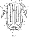
- Figure 1 shows a hand support element 2 for a hand orthosis according to a first embodiment of the present invention.
- the hand support element has two thumb support areas 4 and is symmetrical relative to its longitudinal axis L.
- a palm rest surface 6 has several markings 8 which are designed in the form of depressions 10 and openings 12.
- To cut the hand support element 2 shown one of the two thumb support elements 4 is removed. If the hand support element 2 is to be used for a right hand, the in Figure 1 Thumb support area 4 shown on the left removed. Conversely, if the hand support element 2 is used for a left hand, the in Figure 1 Thumb support area 4 shown on the right removed. Depending on the size of the hand, the hand support element 2 is cut to size along one of the markings 8 shown.
- the illustrated hand support element 2 has slots 14 through which, for example, belts or other fastening elements can be guided and attached to the hand support elements.
- individual fingers of one hand can be attached to a web 16 which is delimited on both sides by a slot.
- FIG 2 shows the hand support element 2 from Figure 1 in a different perspective.
- a representation is now shown from below, while in Figure 1 the illustration is shown from above.
- the two thumb support areas 4, the openings 12 and the slots 14 can also be seen from this underside.
- a fastening element 18, which in this case has a first form-locking element 20, is located in the center. This is designed in the form of a groove and can be closed by a closure 22 which is pivotably arranged. With this fastening element 18, the hand support element 2 can be attached to one in the Figures 1 and 2 not shown support element are attached.
- the Figures 3 and 4 show further components of a hand orthosis according to an embodiment of the present invention.
- eyelets 26 are arranged through which straps or straps can be passed, whereby the forearm shell 24 is arranged on a forearm of the wearer.
- On the left-hand side which, when the hand orthosis is put on, points to the hand, there is a support strut 28 on which a carrier element 30 is arranged.
- the carrier element 30 is displaceably arranged on an elongated hole 32 in the support strut 28. It can also be arranged in two different orientations.
- the carrier element 30 is formed slightly curved. While in the Figures 3 and 4 If a part of a hand orthosis is designed for a left hand, the component for a hand orthosis for a right hand can be made to match by simply turning or repositioning the carrier element 30.
- the support strut 28 is arranged on the forearm shell 24 via an angle adjustment 34, so that an angle can also be adjusted here.
- the carrier element 30 has a taper 36 in which it has a reduced diameter. This is advantageous, but not absolutely necessary.
- the diameter and cross section of this taper 36 of the carrier element 30 is adapted to the first form-locking element 20 on the hand support element 2, as is shown, for example, in FIG Figure 2 is shown. In this way, the hand support element 2 can be arranged on the carrier element 30 in a simple and detachable manner.
Description
- Die Erfindung betrifft ein Handstütztelement für eine Handorthese und eine Handorthese mit einer Manschette zum Befestigen der Handorthese an einem Handgelenk oder einem Unterarm eines Trägers der Handorthese, wenigstens einem Trägerelement und wenigstens einem Handstützelement, das an dem Trägerelement befestigbar ist. Die Erfindung betrifft zudem ein Verfahren zum Anpassen einer solchen Handorthese.
- Handorthesen sind aus dem Stand der Technik seit langem bekannt. Sie verfügen über eine Manschette, mit der die Handorthese an dem Handgelenk oder dem Unterarm des Trägers angeordnet wird. Je nach Einsatzzweck der Handorthese ist diese Manschette unterschiedlich ausgebildet. So gibt es Manschetten, die sich nur über das Handgelenk und einen kleinen Teil des Unterarms erstrecken, um nur eine geringe Stützwirkung aufzubringen, wenn beispielsweise nur ein Daumen gestützt werden soll. Soll hingegen das Handgelenk an sich ruhig gestellt werden, ist eine größere Manschette notwendig, die auch starre oder nur wenig flexible Elemente, beispielsweise Schienen oder Stäbe, aufweisen kann.
- Handorthesen können insbesondere verwendet werden, um mit einem Handstützelement die Handfläche und gegebenenfalls zusätzlich die Finger einer Hand zu stützen und beispielsweise Spastiken vorzubeugen. Ein solches Handstützelement wird dabei vorzugsweise auf der Handinnenseite, also volar angeordnet und die Hand liegt auf dem Handstützelement auf. Selbstverständlich ist es auch möglich, das Handstützelement auf der gegenüberliegenden Seite der Hand, also dorsal, anzuordnen, so dass die Hand an dem Handstützelement befestigt wird, um sie zu stützen.
- Nachteilig ist, dass eine Vielzahl unterschiedlicher Handorthesen vorgehalten werden müssen. So müssen für unterschiedlich große Hände unterschiedlich große Handstützelemente vorgehalten werden. Ist das Handstützelement deutlich größer als die zu stützende Hand, ist es möglich, bei unbedachten Bewegungen der Hand mit dem Handstützelement an Gegenstände, beispielsweise Türen, Schränke oder Tische, anzustoßen. Dadurch werden Schläge und Erschütterungen auf die eigentlich zu stützende und gegebenenfalls ruhig zu stellende Hand übertragen, was unangenehm, gegebenenfalls schmerzhaft und therapeutisch nicht gewollt ist. Ist hingegen das Handstützelement deutlich kleiner als die zu stützende Hand, kann die benötigte Stützwirkung nicht in vollem Umfang erreicht werden, da beispielsweise die letzten Fingerglieder nicht mehr auf dem Handstützelement aufliegen können, so dass diese Fingerglieder nicht gestützt werden.
- Zudem müssen für rechte und linke Hände unterschiedliche Handstützelemente vorgehalten werden.
- Eine derartige Handorthese ist beispielsweise aus der
DE 10 2006 041 441 A1 , derDE 20 2004 005 876 U1 und derDE 20 2015 008 342 U1 bekannt. Eine Handstützeinrichtung wird in derGB 2 425 960 A - Hinzukommt, dass für unterschiedliche Grade an Bewegungsfreiheit, die durch das Handstützelement und die Handorthese weiterhin ermöglicht werden sollen, unterschiedliche Handstützelemente aus dem Stand der Technik bekannt sind. Soll die Hand im Wesentlichen bewegungsfrei bleiben, ist es ausreichend, ein Handstützelement vorzusehen, auf dem die Hand beispielsweise lose aufliegt. Das Handstützelement ist über die Manschette, mit der die Handorthese am Handgelenk oder dem Unterarm des Trägers angeordnet wird, unverlierbar an der Hand angeordnet, die Hand selbst muss am Handstützelement nicht befestigt werden.
- Soll hingegen die Bewegungsfreiheit der Hand deutlich mehr eingeschränkt werden, um beispielsweise Spastiken vorzubeugen, kann es von Vorteil sein, die Hand insgesamt, jeden einzelnen Finger oder nur einzelne Finger am Handauflageelement zu befestigen. Da hierfür unterschiedliche Befestigungselemente, insbesondere Gurte, vorhanden sein müssen, müssen auch in diesen Fällen unterschiedliche Handorthesen mit unterschiedlichen Handstützelementen vorgehalten werden.
- Dies ist nachteilig, da eine große Anzahl unterschiedlicher Handorthesen gefertigt und vorgehalten werden müssen, wodurch sich die Lagerhaltung verteuert.
- Der Erfindung liegt daher die Aufgabe zugrunde, diese Nachteile zu beheben oder zumindest zu verringern.
- Die Erfindung löst die gestellte Aufgabe durch das Handstützelement des Anspruchs 1, die sich dadurch auszeichnet, dass das Handstützelement eine Kontur aufweist, die symmetrisch zu einer Längsachse ausgebildet ist und auf beiden Seiten der Längsachse einen Daumenstützbereich aufweist. Die erfindungsgemäße dazugehörige Handorthese verfügt folglich über ein Handstützelement mit zwei Daumenstützbereichen. Auf diese Weise wird erreicht, dass das Handstützelement sowohl als Stützelement für eine rechte Hand als auch als Stützelement für eine linke Hand verwendet werden kann. Es ist daher nicht mehr notwendig, für rechte und linke Hände unterschiedliche Handstützelemente oder gar unterschiedliche Handorthesen vorzuhalten. Soll die Handorthese an eine rechte oder linke Hand angepasst werden, wird das nicht benötigte Daumenelement entfernt, beispielsweise mit einer Schere abgeschnitten. Selbstverständlich können auch andere Schneidwerkzeuge verwendet werden. Gegebenenfalls werden die Schnittkanten geschliffen und entgratet, um Verletzungsgefahren zu verringern und den Tragekomfort zu erhöhen. Vorteilhafterweise verfügt das Handstützelement über Markierungen, die stilisierte Konturen unterschiedlich großer rechter und/oder linker Hände darstellen. Das Handstützelement kann zum Anpassen der Handorthese an die Hand des Trägers der Handorthese auch in dieser Hinsicht zurecht geschnitten, gekürzt oder konfektioniert werden. Dazu wählt beispielsweise der Orthopädietechniker oder eine andere Person, die die Handorthese anpasst, eine passende Kontur einer rechten oder linken Hand aus und schneidet das Handstützelement entlang dieser Kontur zurecht. Auf diese Weise wird das Handstützelement sowohl an die zu versorgende Seite der Hand, also eine rechte Hand oder eine linke Hand, angepasst, als auch auf die Größe der jeweiligen Hand zugeschnitten. Auch in diesem Fall kann es sinnvoll sein, eventuell auftretende Schnittkanten zu entgraten oder zu glätten.
- Vorzugsweise verfügen die Markierungen über Vertiefungen und/oder Durchbrüche. Dadurch wird das Schneiden entlang der Konturen und Markierungen vereinfacht.
- Handelt es sich um Vertiefungen, verfügt das jeweilige Handstützelement bei diesen Markierungen über eine geringe Dicke, so dass ein Zerschneiden beispielsweise mit einer Schere, deutlich vereinfacht wird. Verfügen die Markierungen hingegen bereits über Durchbrüche, muss an diesen Stellen kein Schnitt mehr durchgeführt werden, sondern es müssen lediglich zwischen den einzelnen Durchbrüchen entlang der Markierung verlaufende Stege durchtrennt werden. Auch dadurch wird der Zuschnitt deutlich vereinfacht.
- Vorzugsweise verfügt das Handstützelement über mehrere, vorzugsweise drei, vier oder fünf Durchbrüche, die sich parallel oder nahezu parallel zur Längsachse des Handstützelementes erstrecken. Diese Durchbrüche sind vorteilhafterweise so angeordnet, dass sie zwischen den Auflageflächen für die einzelnen Finger einer durch das Handstützelement zu stützenden Hand angeordnet sind. Durch sie können Gurte, Riemen oder andere Befestigungselemente hindurchgeführt werden, um auf diese Weise einzelne Finger, Fingergruppen oder die gesamte Hand an dem Handauflageelement zu befestigen. Die Gurte können aus einem elastischen oder einem inelastischen Material hergestellt sein und sind vorzugsweise mit Verschlusselementen, beispielsweise Schnallen, Klettverschlusselementen oder Druckknöpfen ausgerüstet, um eine Befestigung und Fixierung des jeweiligen Körperteils am Handstützelement gewährleisten zu können. Vorzugsweise sind die Befestigungselemente von dem Handstützelement zu entfernen, um sie beispielsweise durch andere Elemente zu ersetzen, falls beispielsweise die Länge der Befestigungselemente anzupassen ist, oder die Befestigungselemente oder das Handstützelement zu reinigen oder zu reparieren.
- Vorzugsweise ist das Handstützelement aus einem Kunststoff hergestellt. Dadurch kann eine angenehme Haptik, ein geringes Gewicht und zudem eine leichte Durchtrennbarkeit des Handstützelementes insbesondere entlang der Markierungen erreicht werden. Zudem ist das Handstützelement vorzugsweise wasserunempfindlich.
- In einer bevorzugten Ausgestaltung verfügt das Handstützelement auf der dem Trägerelement zugewandten Seite über wenigstens ein Befestigungselement, vorzugsweise ein Formschlusselement, das eingerichtet ist, mit einem am Trägerelement angeordneten korrespondierenden Befestigungselement oder Formschlusselement oder dem Trägerelement selbst zusammen zu wirken. Auf diese Weise ist es möglich, das Handstützelement an dem Trägerelement insbesondere formschlüssig zu befestigen. Handelt es sich beispielsweise um eine Clipsverbindung wird dadurch eine leicht lösbare Befestigung erreicht. Vorzugsweise ist das Handstützelement lösbar an dem Trägerelement befestigbar. Dadurch ist es nicht mehr notwendig, das Handstützelement bereits bei der Herstellung der Handorthese mit dem Trägerelement zu verbinden oder es an ihm zu befestigen. Vielmehr kann das Handstützelement beispielsweise vom Orthopädietechniker oder gegebenenfalls sogar vom Patienten an der gewünschten Stelle und in der gewünschten Orientierung und Position am Trägerelement angeordnet werden. Auch dadurch wird die Lagerhaltung verringert und die Flexibilität der Einsetzbarkeit erhöht.
- Die Erfindung löst die gestellte Aufgabe zudem durch ein Handstützelement für eine hier beschriebene Handorthese. Die Erfindung löst die Aufgabe zudem durch ein Verfahren zum Anpassen einer Handorthese gemäß einem Ausführungsbeispiel der vorliegenden Erfindung, wobei bei dem Verfahren ein Daumenstützbereich des Handstützelementes entfernt, bevorzugt abgeschnitten wird. Vorteilhafterweise können dann die Schnittkanten geglättet, entgratet oder auf sonstige Weise nachbehandelt werden, um Verletzungsgefahren zu reduzieren und den Tragekomfort zu erhöhen. Vorteilhafterweise wird das Handstützelement entlang wenigstens einer der Markierungen zugeschnitten.
- Mit Hilfe der beigefügten Zeichnungen wird nachfolgend ein Ausführungsbeispiel der vorliegenden Erfindung näher erläutert. Es zeigen
- Figuren 1 und 2 -
- schematische Darstellungen eines Handstützelementes aus unterschiedlichen Perspektiven und
- Figuren 3 und 4 -
- schematische Darstellungen eines Teils einer Handorthese.
-
Figur 1 zeigt ein Handstützelement 2 für eine Handorthese gemäß einem ersten Ausführungsbeispiel der vorliegenden Erfindung. Das Handstützelement verfügt über zwei Daumenstützbereiche 4 und ist relativ zu seiner Längsachse L symmetrisch ausgebildet. Eine Handauflagefläche 6 verfügt über mehrere Markierungen 8, die in Form von Vertiefungen 10 und Durchbrüche 12 ausgebildet sind. Zum Zuschneiden des gezeigten Handstützelementes 2 wird eines der beiden Daumenstützelemente 4 entfernt. Soll das Handstützelement 2 für eine rechte Hand verwendet werden, wird der inFigur 1 links dargestellte Daumenstützbereich 4 entfernt. Wird umgekehrt das Handstützelement 2 für eine linke Hand verwendet, wird der inFigur 1 rechts dargestellte Daumenstützbereich 4 entfernt. Je nach Größe der Hand wird das Handstützelement 2 entlang einer der dargestellten Markierungen 8 zugeschnitten. - Zusätzlich verfügt das dargestellte Handstützelement 2 über Schlitze 14, durch die beispielsweise Gurte oder andere Befestigungselemente geführt am Handstützelemente befestigt werden können. Auf diese Weise können beispielsweise einzelne Finger einer Hand an einem Steg 16, der auf beiden Seiten durch jeweils einen Schlitz begrenzt wird, befestigt werden. Selbstverständlich ist es auch möglich, einen Gurt oder Riemen durch zwei nicht benachbarte Schlitze 14 zu führen und so mehrere Finger, alle Finger und/oder den Handteller an dem Handstützelement 2 zu befestigen.
-
Figur 2 zeigt das Handstützelement 2 ausFigur 1 in einer anderen Perspektive. Gezeigt ist nun eine Darstellung von unten, während inFigur 1 die Darstellung von oben dargestellt ist. Die beiden Daumenstützbereiche 4, die Durchbrüche 12 und die Schlitze 14 sind auch von dieser Unterseite erkennbar. Zentral befindet sich ein Befestigungselement 18, das in diesem Fall ein erstes Formschlusselement 20 aufweist. Dieses ist in Form einer Rille ausgebildet und durch einen Verschluss 22, der schwenkbar angeordnet ist, verschließbar. Mit diesem Befestigungselement 18 kann das Handstützelement 2 an einem in denFiguren 1 und2 nicht dargestellten Trägerelement befestigt werden. - Die
Figuren 3 und 4 zeigen weitere Bauteile einer Handorthese gemäß einem Ausführungsbeispiel der vorliegenden Erfindung. An einer beispielsweise aus einem Kunststoff hergestellten Unterarmschale 24 sind Ösen 26 angeordnet, durch die Gurte oder Riemen geführt werden können, womit die Unterarmschale 24 an einem Unterarm des Trägers angeordnet ist. In denFiguren 3 und 4 auf der linken Seite, die im angelegten Zustand einer Handorthese der Hand zuweist, befindet sich eine Stützstrebe 28, an der ein Trägerelement 30 angeordnet ist. Das Trägerelement 30 ist an einem Langloch 32 in der Stützstrebe 28 verschieblich angeordnet. Zudem kann es in zwei unterschiedlichen Orientierungen angeordnet werden. Man erkennt insbesondere inFigur 3 , dass das Trägerelement 30 leicht gebogen ausgebildet ist. Während in denFiguren 3 und 4 ein Teil einer Handorthese für eine linke Hand ausgebildet ist, kann durch einfaches Umdrehen oder Umstecken des Trägerelementes 30 das Bauteil für eine Handorthese für eine rechte Hand passend gemacht werden. - Die Stützstrebe 28 ist über eine Winkeleinstellung 34 an der Unterarmschale 24 angeordnet, so dass auch hier ein Winkel eingestellt werden kann.
- Insbesondere in
Figur 4 ist zu erkennen, dass das Trägerelement 30 eine Verjüngung 36 aufweist, in der es einen reduzierten Durchmesser hat. Dies ist vorteilhaft, jedoch nicht zwangsläufig notwendig. Der Durchmesser und Querschnitt dieser Verjüngung 36 des Trägerelementes 30 ist an das erste Formschlusselement 20 am Handstützelement 2 angepasst, wie es beispielsweise inFigur 2 dargestellt ist. Auf diese Weise kann das Handstützelement 2 einfach und lösbar am Trägerelement 30 angeordnet werden. -
- L
- Längsachse
- 2
- Handstützelement
- 4
- Daumenstützbereich
- 6
- Handauflagefläche
- 8
- Markierung
- 10
- Vertiefung
- 12
- Durchbruch
- 14
- Schlitz
- 16
- Steg
- 18
- Befestigungselement
- 20
- erstes Formschlusselement
- 22
- Verschluss
- 24
- Unterarmschale
- 26
- Öse
- 28
- Stützstrebe
- 30
- Trägerelement
- 32
- Langloch
- 34
- Winkeleinstellung
- 36
- Verjüngung
Claims (8)
- Handstützelement (2) für eine Handorthese, wobei das Handstützelement (2) an einem Trägerelement (30) der Handorthese befestigbar ist, dadurch gekennzeichnet, dass das Handstützelement (2) eine Kontur aufweist, die symmetrisch zu einer Längsachse (L) ausgebildet ist und auf beiden Seiten der Längsachse (L) einen Daumenstützbereich aufweist.
- Handstützelement (2) nach Anspruch 1, dadurch gekennzeichnet, dass das Handstützelement (2) Markierungen (8) aufweist, die stilisierte Konturen unterschiedliche großer rechter und linker Hände darstellen.
- Handstützelement (2) nach Anspruch 2, dadurch gekennzeichnet, dass die Markierungen (8) Vertiefungen (10) und/oder Durchbrüche (12) aufweisen.
- Handstützelement (2) nach einem der vorstehenden Ansprüche, dadurch gekennzeichnet, dass das Handstützelement (2) aus einem Kunststoff hergestellt ist.
- Handstützelement (2) nach einem der vorstehenden Ansprüche, dadurch gekennzeichnet, dass das Handstützelement (2) auf der dem Trägerelement (4) zugewandten Seite wenigstens ein Befestigungselement (18), vorzugsweise ein Formschlusselement (20) aufweist, das eingerichtet ist, mit einem am Trägerelement (30) angeordneten korrespondierenden Befestigungselement (36) oder Formschlusselement oder dem Trägerelement (30) zusammenzuwirken
- Handorthese mita. einer Manschette zum Befestigen der Handorthese an einem Handgelenk oder einem Unterarm eines Trägers der Handorthese,b. wenigstens einem Trägerelement (30) undc. wenigstens einem Handstützelement (2) nach einem der vorstehenden Ansprüche.
- Verfahren zum Anpassen einer Handorthese nach Anspruch 6, wobei bei dem Verfahren ein Daumenstützbereich (4) des Handstützelementes (2) entfernt, bevorzugt abgeschnitten wird.
- Verfahren nach Anspruch 7, wobei das Handstützelement (2) entlang wenigstens einer der Markierungen (8) zugeschnitten wird.
Applications Claiming Priority (2)
| Application Number | Priority Date | Filing Date | Title |
|---|---|---|---|
| DE102017127890.7A DE102017127890A1 (de) | 2017-11-24 | 2017-11-24 | Handorthese sowie Verfahren zum Anpassen einer Handorthese |
| PCT/EP2018/081629 WO2019101655A1 (de) | 2017-11-24 | 2018-11-16 | Handorthese sowie verfahren zum anpassen einer handorthese |
Publications (2)
| Publication Number | Publication Date |
|---|---|
| EP3713525A1 EP3713525A1 (de) | 2020-09-30 |
| EP3713525B1 true EP3713525B1 (de) | 2021-09-01 |
Family
ID=64362550
Family Applications (1)
| Application Number | Title | Priority Date | Filing Date |
|---|---|---|---|
| EP18804605.6A Active EP3713525B1 (de) | 2017-11-24 | 2018-11-16 | Handorthese sowie verfahren zum anpassen einer handorthese |
Country Status (5)
| Country | Link |
|---|---|
| US (1) | US20200397606A1 (de) |
| EP (1) | EP3713525B1 (de) |
| CN (1) | CN111372543B (de) |
| DE (1) | DE102017127890A1 (de) |
| WO (1) | WO2019101655A1 (de) |
Family Cites Families (17)
| Publication number | Priority date | Publication date | Assignee | Title |
|---|---|---|---|---|
| US5121743A (en) * | 1990-12-06 | 1992-06-16 | Chester Ingier | Hand restraining device |
| US5733249A (en) * | 1996-03-26 | 1998-03-31 | Katzin, Deceased; Leonard | Deformable orthosis |
| US6443918B1 (en) * | 1999-09-28 | 2002-09-03 | Tzu C. Wang | Adjustable splint |
| DE202004005876U1 (de) * | 2004-04-14 | 2004-09-09 | Lee, Chin-Tsun, Yung Kang | Handschiene |
| DE102004029457A1 (de) * | 2004-06-18 | 2006-01-12 | Oped Ag | Handgelenkorthese |
| GB2425960A (en) * | 2005-05-12 | 2006-11-15 | Ali Bajwa | Adjustable splint |
| NZ540912A (en) * | 2005-06-23 | 2008-03-28 | Ind Res Ltd | An hand orthosis including a hand part, a thumb part and a forearm part, with a flexible connection which draws a user's thumb toward their index finger when the wrist is extended |
| DE102006041441A1 (de) * | 2006-09-04 | 2008-03-06 | Bauerfeind Ag | Handgelenksorthese |
| DE102008005729B4 (de) * | 2008-01-23 | 2009-11-05 | Otto Bock Healthcare Gmbh | Armabduktionsorthese |
| DE102008027439A1 (de) * | 2008-02-08 | 2009-12-10 | Christina Weskott | Finger-Orthese |
| FR2948016B1 (fr) * | 2009-07-17 | 2012-05-18 | Gibaud | Orthese pour le traitement de la rhizarthrose |
| CN203089825U (zh) * | 2013-03-14 | 2013-07-31 | 谭维勇 | 一种关节理疗矫正装置 |
| CN203287912U (zh) * | 2013-06-07 | 2013-11-13 | 刘瑞卿 | 电子指掌纹捺印器 |
| CN203873934U (zh) * | 2014-05-30 | 2014-10-15 | 曹甜甜 | 手腕关节功能矫形器 |
| FR3024030B1 (fr) * | 2014-07-25 | 2016-08-26 | Commissariat Energie Atomique | Dispositif pour l'assistance a la prehension du pouce de la main |
| KR101726649B1 (ko) * | 2015-09-16 | 2017-04-13 | 주식회사 네오펙트 | 손가락 운동장치 |
| DE202015008342U1 (de) * | 2015-12-02 | 2017-03-03 | Hardy Bisinger | Handorthese |
-
2017
- 2017-11-24 DE DE102017127890.7A patent/DE102017127890A1/de not_active Withdrawn
-
2018
- 2018-11-16 WO PCT/EP2018/081629 patent/WO2019101655A1/de unknown
- 2018-11-16 CN CN201880075363.8A patent/CN111372543B/zh active Active
- 2018-11-16 EP EP18804605.6A patent/EP3713525B1/de active Active
- 2018-11-16 US US15/733,123 patent/US20200397606A1/en not_active Abandoned
Also Published As
| Publication number | Publication date |
|---|---|
| DE102017127890A1 (de) | 2019-05-29 |
| CN111372543B (zh) | 2022-11-11 |
| US20200397606A1 (en) | 2020-12-24 |
| CN111372543A (zh) | 2020-07-03 |
| WO2019101655A1 (de) | 2019-05-31 |
| EP3713525A1 (de) | 2020-09-30 |
Similar Documents
| Publication | Publication Date | Title |
|---|---|---|
| EP0164374B1 (de) | Orthese für kniegelenke | |
| EP2544636B1 (de) | Palmare daumen- und daumensattelgelenk-schiene | |
| EP2841030B1 (de) | Daumenorthese | |
| EP0726034B1 (de) | Handschuh | |
| EP2841033B1 (de) | Orthese zum fixieren eines schultergelenks | |
| EP2531151B1 (de) | Schiene zur ruhigstellung eines gelenks | |
| EP2090273B1 (de) | Bandage | |
| EP3666233B1 (de) | Therapiehandschuh und fixierschiene für einen therapiehandschuh | |
| EP1319379B1 (de) | Orthese zur Behandlung von Verletzungen des A-C-Gelenkes der Schulter | |
| DE102013004714B4 (de) | Fingerschiene mit einer ersten und einer zweiten Teilschiene | |
| EP3713525B1 (de) | Handorthese sowie verfahren zum anpassen einer handorthese | |
| EP3421016B1 (de) | Dynamische handorthese | |
| DE102016010135A1 (de) | Orthese zur Ruhigstellung des Karpometakarpalgelenks I | |
| EP4125743B1 (de) | Daumenorthese | |
| EP2480181B1 (de) | Fixierelement sowie anwendung eines solchen fixierelements zum fixieren eines gegenstandes, insbesondere von gliedmassen | |
| DE102020204630A1 (de) | Schutzschale zur medizinischen Abdeckung | |
| WO2019101654A1 (de) | Handorthese und system mit einer handorthese | |
| DE102013017167A1 (de) | Daumenorthese | |
| EP3897476B1 (de) | Knieorthese | |
| DE102019124132B4 (de) | Beissschutz-Vorrichtung | |
| DE102015116931A1 (de) | Orthese mit Schulter- und Armbereich | |
| DE4438568A1 (de) | Handschienenvorrichtung | |
| WO2022162208A1 (de) | Orthese | |
| EP3993659A1 (de) | Vorrichtung in art einer persönlichen schutzausrüstung zur stabilisierung und entlastung des menschlichen daumensattelgelenkes | |
| DE20319742U1 (de) | Orthese zur Fixierung eines Schultergelenkes |
Legal Events
| Date | Code | Title | Description |
|---|---|---|---|
| STAA | Information on the status of an ep patent application or granted ep patent |
Free format text: STATUS: UNKNOWN |
|
| STAA | Information on the status of an ep patent application or granted ep patent |
Free format text: STATUS: THE INTERNATIONAL PUBLICATION HAS BEEN MADE |
|
| PUAI | Public reference made under article 153(3) epc to a published international application that has entered the european phase |
Free format text: ORIGINAL CODE: 0009012 |
|
| STAA | Information on the status of an ep patent application or granted ep patent |
Free format text: STATUS: REQUEST FOR EXAMINATION WAS MADE |
|
| 17P | Request for examination filed |
Effective date: 20200616 |
|
| AK | Designated contracting states |
Kind code of ref document: A1 Designated state(s): AL AT BE BG CH CY CZ DE DK EE ES FI FR GB GR HR HU IE IS IT LI LT LU LV MC MK MT NL NO PL PT RO RS SE SI SK SM TR |
|
| AX | Request for extension of the european patent |
Extension state: BA ME |
|
| GRAP | Despatch of communication of intention to grant a patent |
Free format text: ORIGINAL CODE: EPIDOSNIGR1 |
|
| STAA | Information on the status of an ep patent application or granted ep patent |
Free format text: STATUS: GRANT OF PATENT IS INTENDED |
|
| INTG | Intention to grant announced |
Effective date: 20201211 |
|
| DAV | Request for validation of the european patent (deleted) | ||
| DAX | Request for extension of the european patent (deleted) | ||
| GRAJ | Information related to disapproval of communication of intention to grant by the applicant or resumption of examination proceedings by the epo deleted |
Free format text: ORIGINAL CODE: EPIDOSDIGR1 |
|
| STAA | Information on the status of an ep patent application or granted ep patent |
Free format text: STATUS: REQUEST FOR EXAMINATION WAS MADE |
|
| GRAP | Despatch of communication of intention to grant a patent |
Free format text: ORIGINAL CODE: EPIDOSNIGR1 |
|
| STAA | Information on the status of an ep patent application or granted ep patent |
Free format text: STATUS: GRANT OF PATENT IS INTENDED |
|
| INTC | Intention to grant announced (deleted) | ||
| INTG | Intention to grant announced |
Effective date: 20210401 |
|
| GRAS | Grant fee paid |
Free format text: ORIGINAL CODE: EPIDOSNIGR3 |
|
| GRAA | (expected) grant |
Free format text: ORIGINAL CODE: 0009210 |
|
| STAA | Information on the status of an ep patent application or granted ep patent |
Free format text: STATUS: THE PATENT HAS BEEN GRANTED |
|
| AK | Designated contracting states |
Kind code of ref document: B1 Designated state(s): AL AT BE BG CH CY CZ DE DK EE ES FI FR GB GR HR HU IE IS IT LI LT LU LV MC MK MT NL NO PL PT RO RS SE SI SK SM TR |
|
| REG | Reference to a national code |
Ref country code: GB Ref legal event code: FG4D Free format text: NOT ENGLISH |
|
| REG | Reference to a national code |
Ref country code: CH Ref legal event code: EP Ref country code: AT Ref legal event code: REF Ref document number: 1425415 Country of ref document: AT Kind code of ref document: T Effective date: 20210915 |
|
| REG | Reference to a national code |
Ref country code: DE Ref legal event code: R096 Ref document number: 502018006904 Country of ref document: DE |
|
| REG | Reference to a national code |
Ref country code: IE Ref legal event code: FG4D Free format text: LANGUAGE OF EP DOCUMENT: GERMAN |
|
| REG | Reference to a national code |
Ref country code: SE Ref legal event code: TRGR |
|
| REG | Reference to a national code |
Ref country code: NL Ref legal event code: FP |
|
| REG | Reference to a national code |
Ref country code: LT Ref legal event code: MG9D |
|
| PG25 | Lapsed in a contracting state [announced via postgrant information from national office to epo] |
Ref country code: RS Free format text: LAPSE BECAUSE OF FAILURE TO SUBMIT A TRANSLATION OF THE DESCRIPTION OR TO PAY THE FEE WITHIN THE PRESCRIBED TIME-LIMIT Effective date: 20210901 Ref country code: HR Free format text: LAPSE BECAUSE OF FAILURE TO SUBMIT A TRANSLATION OF THE DESCRIPTION OR TO PAY THE FEE WITHIN THE PRESCRIBED TIME-LIMIT Effective date: 20210901 Ref country code: ES Free format text: LAPSE BECAUSE OF FAILURE TO SUBMIT A TRANSLATION OF THE DESCRIPTION OR TO PAY THE FEE WITHIN THE PRESCRIBED TIME-LIMIT Effective date: 20210901 Ref country code: FI Free format text: LAPSE BECAUSE OF FAILURE TO SUBMIT A TRANSLATION OF THE DESCRIPTION OR TO PAY THE FEE WITHIN THE PRESCRIBED TIME-LIMIT Effective date: 20210901 Ref country code: LT Free format text: LAPSE BECAUSE OF FAILURE TO SUBMIT A TRANSLATION OF THE DESCRIPTION OR TO PAY THE FEE WITHIN THE PRESCRIBED TIME-LIMIT Effective date: 20210901 Ref country code: BG Free format text: LAPSE BECAUSE OF FAILURE TO SUBMIT A TRANSLATION OF THE DESCRIPTION OR TO PAY THE FEE WITHIN THE PRESCRIBED TIME-LIMIT Effective date: 20211201 Ref country code: NO Free format text: LAPSE BECAUSE OF FAILURE TO SUBMIT A TRANSLATION OF THE DESCRIPTION OR TO PAY THE FEE WITHIN THE PRESCRIBED TIME-LIMIT Effective date: 20211201 |
|
| PG25 | Lapsed in a contracting state [announced via postgrant information from national office to epo] |
Ref country code: PL Free format text: LAPSE BECAUSE OF FAILURE TO SUBMIT A TRANSLATION OF THE DESCRIPTION OR TO PAY THE FEE WITHIN THE PRESCRIBED TIME-LIMIT Effective date: 20210901 Ref country code: LV Free format text: LAPSE BECAUSE OF FAILURE TO SUBMIT A TRANSLATION OF THE DESCRIPTION OR TO PAY THE FEE WITHIN THE PRESCRIBED TIME-LIMIT Effective date: 20210901 Ref country code: GR Free format text: LAPSE BECAUSE OF FAILURE TO SUBMIT A TRANSLATION OF THE DESCRIPTION OR TO PAY THE FEE WITHIN THE PRESCRIBED TIME-LIMIT Effective date: 20211202 |
|
| PG25 | Lapsed in a contracting state [announced via postgrant information from national office to epo] |
Ref country code: IS Free format text: LAPSE BECAUSE OF FAILURE TO SUBMIT A TRANSLATION OF THE DESCRIPTION OR TO PAY THE FEE WITHIN THE PRESCRIBED TIME-LIMIT Effective date: 20220101 Ref country code: SM Free format text: LAPSE BECAUSE OF FAILURE TO SUBMIT A TRANSLATION OF THE DESCRIPTION OR TO PAY THE FEE WITHIN THE PRESCRIBED TIME-LIMIT Effective date: 20210901 Ref country code: SK Free format text: LAPSE BECAUSE OF FAILURE TO SUBMIT A TRANSLATION OF THE DESCRIPTION OR TO PAY THE FEE WITHIN THE PRESCRIBED TIME-LIMIT Effective date: 20210901 Ref country code: RO Free format text: LAPSE BECAUSE OF FAILURE TO SUBMIT A TRANSLATION OF THE DESCRIPTION OR TO PAY THE FEE WITHIN THE PRESCRIBED TIME-LIMIT Effective date: 20210901 Ref country code: PT Free format text: LAPSE BECAUSE OF FAILURE TO SUBMIT A TRANSLATION OF THE DESCRIPTION OR TO PAY THE FEE WITHIN THE PRESCRIBED TIME-LIMIT Effective date: 20220103 Ref country code: EE Free format text: LAPSE BECAUSE OF FAILURE TO SUBMIT A TRANSLATION OF THE DESCRIPTION OR TO PAY THE FEE WITHIN THE PRESCRIBED TIME-LIMIT Effective date: 20210901 Ref country code: CZ Free format text: LAPSE BECAUSE OF FAILURE TO SUBMIT A TRANSLATION OF THE DESCRIPTION OR TO PAY THE FEE WITHIN THE PRESCRIBED TIME-LIMIT Effective date: 20210901 Ref country code: AL Free format text: LAPSE BECAUSE OF FAILURE TO SUBMIT A TRANSLATION OF THE DESCRIPTION OR TO PAY THE FEE WITHIN THE PRESCRIBED TIME-LIMIT Effective date: 20210901 |
|
| REG | Reference to a national code |
Ref country code: DE Ref legal event code: R097 Ref document number: 502018006904 Country of ref document: DE |
|
| PG25 | Lapsed in a contracting state [announced via postgrant information from national office to epo] |
Ref country code: MC Free format text: LAPSE BECAUSE OF FAILURE TO SUBMIT A TRANSLATION OF THE DESCRIPTION OR TO PAY THE FEE WITHIN THE PRESCRIBED TIME-LIMIT Effective date: 20210901 |
|
| PLBE | No opposition filed within time limit |
Free format text: ORIGINAL CODE: 0009261 |
|
| STAA | Information on the status of an ep patent application or granted ep patent |
Free format text: STATUS: NO OPPOSITION FILED WITHIN TIME LIMIT |
|
| REG | Reference to a national code |
Ref country code: CH Ref legal event code: PL |
|
| PG25 | Lapsed in a contracting state [announced via postgrant information from national office to epo] |
Ref country code: LU Free format text: LAPSE BECAUSE OF NON-PAYMENT OF DUE FEES Effective date: 20211116 Ref country code: DK Free format text: LAPSE BECAUSE OF FAILURE TO SUBMIT A TRANSLATION OF THE DESCRIPTION OR TO PAY THE FEE WITHIN THE PRESCRIBED TIME-LIMIT Effective date: 20210901 Ref country code: BE Free format text: LAPSE BECAUSE OF NON-PAYMENT OF DUE FEES Effective date: 20211130 |
|
| REG | Reference to a national code |
Ref country code: BE Ref legal event code: MM Effective date: 20211130 |
|
| 26N | No opposition filed |
Effective date: 20220602 |
|
| PG25 | Lapsed in a contracting state [announced via postgrant information from national office to epo] |
Ref country code: SI Free format text: LAPSE BECAUSE OF FAILURE TO SUBMIT A TRANSLATION OF THE DESCRIPTION OR TO PAY THE FEE WITHIN THE PRESCRIBED TIME-LIMIT Effective date: 20210901 |
|
| PG25 | Lapsed in a contracting state [announced via postgrant information from national office to epo] |
Ref country code: IE Free format text: LAPSE BECAUSE OF NON-PAYMENT OF DUE FEES Effective date: 20211116 |
|
| PG25 | Lapsed in a contracting state [announced via postgrant information from national office to epo] |
Ref country code: CY Free format text: LAPSE BECAUSE OF FAILURE TO SUBMIT A TRANSLATION OF THE DESCRIPTION OR TO PAY THE FEE WITHIN THE PRESCRIBED TIME-LIMIT Effective date: 20210901 |
|
| PG25 | Lapsed in a contracting state [announced via postgrant information from national office to epo] |
Ref country code: LI Free format text: LAPSE BECAUSE OF NON-PAYMENT OF DUE FEES Effective date: 20220701 Ref country code: HU Free format text: LAPSE BECAUSE OF FAILURE TO SUBMIT A TRANSLATION OF THE DESCRIPTION OR TO PAY THE FEE WITHIN THE PRESCRIBED TIME-LIMIT; INVALID AB INITIO Effective date: 20181116 Ref country code: CH Free format text: LAPSE BECAUSE OF NON-PAYMENT OF DUE FEES Effective date: 20220701 |
|
| PGFP | Annual fee paid to national office [announced via postgrant information from national office to epo] |
Ref country code: NL Payment date: 20231122 Year of fee payment: 6 |
|
| PGFP | Annual fee paid to national office [announced via postgrant information from national office to epo] |
Ref country code: GB Payment date: 20231123 Year of fee payment: 6 |
|
| PGFP | Annual fee paid to national office [announced via postgrant information from national office to epo] |
Ref country code: TR Payment date: 20231107 Year of fee payment: 6 Ref country code: SE Payment date: 20231123 Year of fee payment: 6 Ref country code: IT Payment date: 20231130 Year of fee payment: 6 Ref country code: FR Payment date: 20231124 Year of fee payment: 6 Ref country code: DE Payment date: 20231120 Year of fee payment: 6 |