EP3712097B1 - Textile machine and teaching method - Google Patents
Textile machine and teaching method Download PDFInfo
- Publication number
- EP3712097B1 EP3712097B1 EP20160905.4A EP20160905A EP3712097B1 EP 3712097 B1 EP3712097 B1 EP 3712097B1 EP 20160905 A EP20160905 A EP 20160905A EP 3712097 B1 EP3712097 B1 EP 3712097B1
- Authority
- EP
- European Patent Office
- Prior art keywords
- yarn threading
- assisting member
- yarn
- yarns
- guide
- Prior art date
- Legal status (The legal status is an assumption and is not a legal conclusion. Google has not performed a legal analysis and makes no representation as to the accuracy of the status listed.)
- Active
Links
- 239000004753 textile Substances 0.000 title claims description 18
- 238000000034 method Methods 0.000 title claims description 16
- 238000004804 winding Methods 0.000 claims description 25
- 230000002940 repellent Effects 0.000 claims description 10
- 239000005871 repellent Substances 0.000 claims description 10
- 230000036544 posture Effects 0.000 description 32
- 238000003825 pressing Methods 0.000 description 22
- 238000003860 storage Methods 0.000 description 3
- 238000010586 diagram Methods 0.000 description 2
- 230000005489 elastic deformation Effects 0.000 description 2
- 238000003780 insertion Methods 0.000 description 2
- 230000037431 insertion Effects 0.000 description 2
- 238000012986 modification Methods 0.000 description 2
- 230000004048 modification Effects 0.000 description 2
- 238000009987 spinning Methods 0.000 description 2
- JOYRKODLDBILNP-UHFFFAOYSA-N Ethyl urethane Chemical compound CCOC(N)=O JOYRKODLDBILNP-UHFFFAOYSA-N 0.000 description 1
- 238000013459 approach Methods 0.000 description 1
- 230000015572 biosynthetic process Effects 0.000 description 1
- 230000006835 compression Effects 0.000 description 1
- 238000007906 compression Methods 0.000 description 1
- 238000005520 cutting process Methods 0.000 description 1
- 230000003247 decreasing effect Effects 0.000 description 1
- 238000000926 separation method Methods 0.000 description 1
Images


Classifications
-
- B—PERFORMING OPERATIONS; TRANSPORTING
- B65—CONVEYING; PACKING; STORING; HANDLING THIN OR FILAMENTARY MATERIAL
- B65H—HANDLING THIN OR FILAMENTARY MATERIAL, e.g. SHEETS, WEBS, CABLES
- B65H57/00—Guides for filamentary materials; Supports therefor
- B65H57/003—Arrangements for threading or unthreading the guide
-
- D—TEXTILES; PAPER
- D01—NATURAL OR MAN-MADE THREADS OR FIBRES; SPINNING
- D01D—MECHANICAL METHODS OR APPARATUS IN THE MANUFACTURE OF ARTIFICIAL FILAMENTS, THREADS, FIBRES, BRISTLES OR RIBBONS
- D01D7/00—Collecting the newly-spun products
-
- B—PERFORMING OPERATIONS; TRANSPORTING
- B65—CONVEYING; PACKING; STORING; HANDLING THIN OR FILAMENTARY MATERIAL
- B65H—HANDLING THIN OR FILAMENTARY MATERIAL, e.g. SHEETS, WEBS, CABLES
- B65H57/00—Guides for filamentary materials; Supports therefor
- B65H57/16—Guides for filamentary materials; Supports therefor formed to maintain a plurality of filaments in spaced relation
-
- B—PERFORMING OPERATIONS; TRANSPORTING
- B65—CONVEYING; PACKING; STORING; HANDLING THIN OR FILAMENTARY MATERIAL
- B65H—HANDLING THIN OR FILAMENTARY MATERIAL, e.g. SHEETS, WEBS, CABLES
- B65H67/00—Replacing or removing cores, receptacles, or completed packages at paying-out, winding, or depositing stations
- B65H67/04—Arrangements for removing completed take-up packages and or replacing by cores, formers, or empty receptacles at winding or depositing stations; Transferring material between adjacent full and empty take-up elements
- B65H67/044—Continuous winding apparatus for winding on two or more winding heads in succession
- B65H67/048—Continuous winding apparatus for winding on two or more winding heads in succession having winding heads arranged on rotary capstan head
-
- B—PERFORMING OPERATIONS; TRANSPORTING
- B65—CONVEYING; PACKING; STORING; HANDLING THIN OR FILAMENTARY MATERIAL
- B65H—HANDLING THIN OR FILAMENTARY MATERIAL, e.g. SHEETS, WEBS, CABLES
- B65H2701/00—Handled material; Storage means
- B65H2701/30—Handled filamentary material
- B65H2701/31—Textiles threads or artificial strands of filaments
Definitions
- the present invention relates to a textile machine and a teaching method for the textile machine.
- Patent Literature 1 JP 2015-164875 A is related to the preamble of claim 1 and recites a yarn winder which is configured to wind yarns onto bobbins while traversing the yarns.
- the yarn winder includes fulcrum guides provided to correspond to the respective bobbins and an assisting tool guide (assisting member guide unit) which guides, in a predetermined direction, a yarn threading assisting tool (yarn threading assisting member) which is provided to thread the yarns to the plural fulcrum guides at once.
- Patent Literature 2 JP 2017-82379 A recites an automatic yarn threading device for automating operations such as yarn threading to the fulcrum guides.
- the automatic yarn threading device includes a robotic arm to which a yarn threading unit is attached and a yarn threading control unit (controller).
- the yarn threading unit includes the above-described yarn threading assisting member (yarn separation guide in Patent Literature 2).
- the yarn threading control unit drives and controls the robotic arm. As the controller drives and controls the robotic arm, the yarn threading assisting member is moved and yarns are automatically threaded to the fulcrum guides.
- Patent Literature 2 is silent on the assisting member guide unit. In other words, the automatic yarn threading device moves the yarn threading assisting member without using the assisting member guide unit.
- Patent Literature 3 ( EP 3 415 452 A1 ) is related to a yarn threading robot configured to thread the yarn to a take-up unit, in which movement information related to a robotic arm is stored and corrected using information acquired by a sensor.
- the first object of the present invention is to successfully perform yarn threading in a textile machine by suppressing application of excessive force to a yarn threading assisting member without needing complex control, when the yarn threading assisting member of an automatic yarn threading device is in contact with an assisting member guide unit.
- the second object of the present invention is to shorten the time required for teaching in a teaching method of storing operation information regarding the yarn threading in a controller.
- a textile machine includes: a winding device which includes a bobbin holder supporting bobbins which are aligned along a bobbin axial direction and fulcrum guides about which yarns wound onto to respective bobbins are traversed, the winding device being configured to wind the yarns onto the bobbins; and an automatic yarn threading device which includes a yarn threading assisting member configured to temporarily hold the yarns and a driving mechanism configured to drive and move the yarn threading assisting member, the driving mechanism driving the yarn threading assisting member so that the automatic yarn threading device performing yarn threading of threading the yarns to the fulcrum guides, the winding device including an assisting member guide unit on which a guide surface is formed to guide the yarn threading assisting member in a guide direction having a component in the bobbin axial direction, and the automatic yarn threading device including a cushion member which absorbs repellent force applied from the guide surface to the yarn threading assisting member.
- the repellent force from the guide surface to the yarn threading assisting member is absorbed by the cushion member.
- a yarn threading assisting member of an automatic yarn threading device is in contact with an assisting member guide unit, application of excessive force to the yarn threading assisting member is suppressed without needing complicated control, and hence the yarn threading is properly done.
- the textile machine of the first aspect is arranged such that the cushion member includes an elastic member which biases, by means of elastic restoring force, the yarn threading assisting member toward the guide surface in an intersecting direction intersecting with the guide direction.
- the yarn threading assisting member is actively made contact with the guide surface within a range of elastic deformation of the elastic member. It is therefore possible to easily make the yarn threading assisting member in contact with the guide surface, without needing rigorous position control of the yarn threading assisting member.
- the textile machine of claim 2 is arranged such that the cushion member includes a rotatable component which is rotatable in the intersecting direction, the yarn threading assisting member being attached to the rotatable component, and the elastic member biases the rotatable component toward the guide surface in the intersecting direction.
- the elastic member may be directly attached to the yarn threading assisting member. In this case, however, it is difficult to secure a wide movable range of the yarn threading assisting member. In the present invention, because the rotatable component is biased, the movable range of the yarn threading assisting member is widened because, for example, the yarn threading assisting member is attached to the leading end portion of the rotatable component.
- the textile machine of claim 3 is arranged such that the elastic member is a torsion spring provided to surround a rotation center of the rotatable component.
- the rotatable component is biased with a simple arrangement.
- the biasing force is therefore easily adjustable.
- the textile machine of any one of the first to fourth claims further includes a controller which is configured to control the driving mechanism, the controller controlling the driving mechanism so that the yarn threading assisting member moves while being always in contact with the guide surface.
- the yarn threading assisting member as the yarn threading assisting member is moved while being always in contact with the guide surface in the yarn threading, the yarns are reliably threaded to the fulcrum guides. It is therefore possible to successfully perform the yarn threading without needing rigorous control of the driving mechanism.
- a teaching method is a teaching method of performing teaching to store operation information regarding the yarn threading in the controller controlling the driving mechanism, in the textile machine of any one of the first to fifth aspects, the method comprising the step of storing the operation information in the controller so that the yarn threading assisting member is always in contact with the guide surface from start to end of the yarn threading.
- the teaching When the teaching is performed without using the assisting member guide unit, it is necessary to repeatedly check the operation of the automatic yarn threading device in order to ensure the threading of the yarns to the fulcrum guides, and to determine the moving path of the yarn threading assisting member through trial and error.
- the moving path of the yarn threading assisting member is determined in advance by the guide surface of the assisting member guide unit, the number of times of the operation check is significantly reduced as compared to cases where the yarn threading is performed without using the assisting member guide unit. The time required for the teaching is therefore significantly shortened.
- the teaching method of the sixth claim is arranged such that the teaching is performed while the yarn threading assisting member does not hold the yarns.
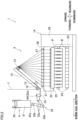
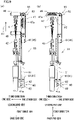
- FIG. 1 is a front elevation of a spun yarn take-up machine 1 (textile machine of the present invention) of the present embodiment.
- the spun yarn take-up machine 1 includes take-up units 3 and a yarn threading robot 4 (automatic yarn threading device of the present invention).
- the take-up units 3 are aligned in the left-right direction and each of the take-up units 3 takes up yarns Y spun out from a spinning apparatus (not illustrated) provided above the take-up units 3, and form packages P by winding the yarns Y onto bobbins B.
- the yarn threading robot 4 is movable in the left-right direction and performs operations to thread the yarns Y to parts constituting each take-up unit 3.
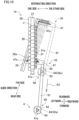
- FIG. 2 is a profile of the take-up unit 3.
- the take-up unit 3 includes a first godet roller 12, a second godet roller 13, and a winding device 14.
- the first godet roller 12 is a roller having an axis substantially in parallel to the left-right direction and is provided above a front end portion of the winding device 14.
- the first godet roller 12 is rotationally driven by a first godet motor 111 (see FIG. 5 ).
- the second godet roller 13 is a roller having an axis substantially in parallel to the left-right direction, and is provided above and rearward of the first godet roller 12.
- the second godet roller 13 is rotationally driven by a second godet motor 112 (see FIG. 5 ).
- the second godet roller 13 is movably supported by the guide rail 15.
- the guide rail 15 extends obliquely upward and rearward.
- the second godet roller 13 is movable along the guide rail 15 by, for example, a motor 113 (see FIG. 5 ) and unillustrated members such as a pulley pair, a belt, and an air device. With this, the second godet roller 13 is movable between a position which is indicated by full lines in FIG. 2 , where winding of the yarns Y is carried out and a position which is indicated by dashed lines in FIG. 2 , where the second godet roller 13 is close to the first godet roller 12 and yarn threading is carried out.
- FIG. 3(a) shows the positions of the fulcrum guides 21 (described later) when the yarns Y are wound.
- FIG. 3(b) shows the positions of the fulcrum guides 21 when the yarn threading is carried out.
- the winding device 14 is arranged to perform winding such that the yarns Y are wound onto bobbins B and package P are formed.
- the winding device 14 is provided below the first godet roller 12 and the second godet roller 13.
- the winding device 14 includes fulcrum guides 21, traverse guides 22, a turret 23, two bobbin holders 24, and a contact roller 25.
- Each of the fulcrum guides 21 is a guide about which a yarn Y is traversed by a traverse guide 22. As shown in FIG. 2 and FIGs. 3(a) and 3(b) , the fulcrum guides 21 are provided for the respective yarns Y and are aligned in the front-rear direction (bobbin axial direction). Each fulcrum guide 21 has a groove 21a which is open to the rear side. A yarn Y can be housed in each fulcrum guide 21 as the yarn Y is inserted into the groove 21a from the rear side. As shown in FIG. 3(a) and FIG. 3(b) , the fulcrum guides 21 are attached to sliders 26, respectively.
- the sliders 26 are supported to be movable along the guide rail 27 which extends in the front-rear direction.
- the sliders 26 are connected to a cylinder 114 (see FIG. 5 ).
- the fulcrum guides 21 are movable between winding positions where the fulcrum guides 21 are separated from one another in the front-rear direction and the yarns Y are wound (see FIG. 3(a) ) and yarn threading positions where the fulcrum guides 21 are close to one another at a front part of the guide rail 27 and yarn threading is performed (see FIG. 3(b) ).
- a supporting member 28 extending in the front-rear direction is provided below the guide rail 27, a supporting member 28 extending in the front-rear direction is provided.
- the supporting member 28 is attached to a base frame 20 (see FIG. 2 ) and supports the guide rail 27.
- an assisting member guide unit 29 (see FIG. 3 ) is attached to guide a later-described yarn threading assisting member 47 (see, e.g., FIG. 4(a) ).
- the assisting member guide unit 29 has a guide surface 29a which extends at least in the front-rear direction. A side face of the yarn threading assisting member 47 makes contact with this guide surface 29a.
- the assisting member guide unit 29 is switchable between a retreat posture in which the assisting member guide unit 29 is parallel to the supporting member 28 and a guide posture (see FIG.
- the posture of the assisting member guide unit 29 is switched as the assisting member guide unit 29 is driven by a cylinder 115 (see FIG. 5 ), for example.
- the direction in which the guide surface 29a extends when the assisting member guide unit 29 takes the guide posture will be referred to as a guide direction.
- the guide direction has a component in the front-rear direction (bobbin axial direction) and a component in the left-right direction.
- the front and left side of the guide surface 29a will be referred to as a near side, whereas the rear and right side of the guide surface 29a will be referred to as a far side (see FIG. 3(b) ).
- the traverse guides 22 are provided for the respective yarns Y and are aligned in the front-rear direction.
- Each traverse guide 22 is driven by a traverse motor 116 (see FIG. 5 ) and reciprocates in the front-rear direction. With this, the yarns Y threaded to the traverse guides 22 are traversed about the fulcrum guides 21.
- the turret 23 is a disc-shaped member having an axis which is in parallel to the front-rear direction.
- the turret 23 is rotationally driven by a turret motor which is not illustrated.
- the two bobbin holders 24 have axes in parallel to the front-rear direction and are rotatably supported at an upper end portion and a lower end portion of the turret 23, respectively.
- Each bobbin holder 24 supports bobbins B which are aligned in the front-rear direction (bobbin axial direction).
- Each of the two bobbin holders 24 is rotationally driven by an individual winding motor 117 (see FIG. 5 ).
- the contact roller 25 is a roller having an axis substantially in parallel to the front-rear direction and is provided immediately above the upper bobbin holder 24.
- the contact roller 25 is configured to make contact with the surfaces of the packages P supported by the upper bobbin holder 24. With this, the contact roller 25 applies a contact pressure to the surfaces of the unfinished packages P, to adjust the shape of each package P.
- the yarns Y traversed by the traverse guides 22 are wound onto the bobbins B, with the result that the packages P are formed (winding).
- the turret 23 rotates to switch over the upper and lower positions of the two bobbin holders 24.
- the bobbin holder 24 having been at the lower position is moved to the upper position, which allows the yarns Y to be wound onto the bobbins B attached to the bobbin holder 24 having been moved to the upper position, to form packages P.
- the bobbin holder 24 to which the fully-formed packages P are attached is moved to the lower position, and the packages P are collected by, for example, an unillustrated package collector.
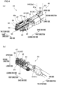
- FIG. 4(a) and FIG. 4(b) are perspective views of a later-described yarn threading unit 33.
- the yarn threading robot 4 threads the yarns Y to the first godet roller 12, the second godet roller 13, the fulcrum guides 21, etc.
- the yarn threading robot 4 includes a main body 31, a robotic arm 32 (driving mechanism of the present invention), and a yarn threading unit 33.
- the main body 31 is formed to be substantially rectangular parallelepiped in shape. Inside the main body 31, a yarn threading control unit 102 (controller of the present invention; see FIG. 5 ) is provided to control operations of the robotic arm 32, etc. In front of the take-up units 3, a rail member 35 is provided to extend in the left-right direction. The main body 31 is suspended from the rail member 35 and is moved in the left-right direction along the rail member 35 by a main body moving device 121 (see FIG. 5 ).
- a main body moving device 121 see FIG. 5 .
- the robotic arm 32 is attached to the lower surface of the main body 31.
- the robotic arm 32 includes arms 32a and joints 32b connecting the arms 32a with one another.
- Each joint 32b incorporates therein an arm motor 122 (see FIG. 5 ).
- the arm motor 122 see FIG. 5
- the arm 32a is swung about the joint 32b.
- the yarn threading unit 33 is attached to a leading end portion of the robotic arm 32. As shown in FIG. 4(a) and FIG. 4(b) , the yarn threading unit 33 is arranged to be long in one direction (hereinafter, first direction). An end portion of the yarn threading unit 33, which is on one side in the first direction (hereinafter, a base end side in the first direction), is connected to an arm 32a (arm 64) which is at the leading end of the robotic arm 32.
- the side opposite to the base end side in the first direction will be referred to as a leading end side.
- the yarn threading unit 33 attached to the leading end portion of the robot arm 32 moves.
- the orientation of the yarn threading unit 33 is changeable.
- the yarn threading unit 33 is mainly used in an orientation with which the up-down direction in FIG. 4(a) and FIG. 4(b) is substantially in parallel to the vertical direction, the upper side in FIG. 4(a) and FIG. 4(b) is the upper side in the vertical direction, and the lower side in FIG. 4(a) and FIG. 4(b) is the lower side in the vertical direction.
- directions relative to the yarn threading unit 33 are defined as follows: the up-down direction in FIG.
- FIG. 4(a) and FIG. 4(b) is referred to as a second direction; the upper side in FIG. 4(a) and FIG. 4(b) is referred to as the upper side in the second direction; and the lower side in FIG. 4(a) and FIG. 4(b) is referred to as the lower side in the second direction.
- the direction orthogonal to both the first direction and the second direction is referred to as a third direction.
- one side and the other side in the third direction will be used in the explanations below.
- the yarn threading unit 33 includes a frame 41, a suction 42, a cutter 44, a slidable component 45, a pressing roller 46, and a yarn threading assisting member 47.
- the frame 41 is a long component extending in the first direction.
- a base end portion (base end member 41a) in the first direction of the frame 41 is connected to the arm 32a (arm 64) which is at the leading end of the robotic arm 32 (details will be given later).
- the suction 42 extends in the first direction and is able to suck and retain the yarns Y at its leading end portion.
- the suction 42 is attached to a part of the frame 41, which is on the one side in the third direction.
- the cutter 44 is attached to the frame 41 and is below the suction 42 in the second direction. The cutter 44 is, for example, used for cutting unnecessary part of the yarns Y when the suction 42 sucks and retains the yarns Y.
- the slidable component 45 is provided on the other side of the suction 42 in the third direction.
- the slidable component 45 is attached to the frame 41 via a cylinder 51.
- the cylinder 51 As the cylinder 51 is driven, the slidable component 45 moves in the first direction relative to the frame 41.
- both of the frame 41 and the slidable component 45 extend in the first direction.
- the frame 41 and the slidable component 45 may be collectively termed an extending member 61.
- a cylindrical shaft 52 is provided to penetrate the slidable component 45 in the second direction.
- the shaft 52 rotatably supports the pressing roller 46.
- a cylindrical shaft 54 is provided to be rotatable relative to the shaft 52.
- the shaft 54 rotatably supports the yarn threading assisting member 47.
- the pressing roller 46 is rotatably supported by a shaft 46a which is orthogonal to the second direction.
- the pressing roller 46 is provided above the slidable component 45 in the second direction.
- One end portion of the shaft 46a is attached to the shaft 52.
- the pressing roller 46 is rotationally driven by a roller rotation device 53 to be rotated about the shaft 52.
- the roller rotation device 53 is able to switch the posture of the pressing roller between an initial posture (see FIG. 4(a) ) in which the pressing roller is substantially parallel to the first direction and a pressing posture (see FIG. 9(a) ) in which the pressing roller is substantially parallel to the third direction.
- the yarn threading assisting member 47 temporarily holds the yarns Y when the yarns Y are threaded to the fulcrum guides 21.
- the yarn threading assisting member 47 is provided above the pressing roller 46 in the second direction.
- grooves 47a are formed to be aligned in the longitudinal direction of the yarn threading assisting member 47.
- Each of the grooves 47a is open at one end.
- the intervals between the grooves 47a increase in the direction away from the open ends.
- One end portion in the longitudinal direction of the yarn threading assisting member 47 is attached to the shaft 54.
- the yarn threading assisting member 47 is rotationally driven by an assisting member rotation device 55 so as to be rotated about the shaft 54.
- the assisting member rotation device 55 is able to switch the posture of the yarn threading assisting member 47 between an initial posture (see FIG. 4(a) ) in which the yarn threading assisting member 47 is substantially parallel to the first direction and a yarn threading posture (see FIG. 9(b) ) in which the yarn threading assisting member 47 is substantially parallel to the third direction.
- each take-up unit controller 101 controls members such as the first godet motor 111, the second godet motor 112, the motor 113, the cylinder 114, the cylinder 115, the traverse motor 116, and the winding motors 117.
- each take-up unit 3 includes two winding motors 117, FIG. 5 shows only one winding motor 117.
- FIG. 5 shows only one traverse motor 116, each take-up unit 3 may include plural traverse motors 116.
- the yarn threading control unit 102 is provided in the yarn threading robot 4.
- the yarn threading control unit 102 controls members such as the main body moving device 121, the arm motor 122, the suction 42, the cutter 44, the cylinder 51, the roller rotation device 53, and the assisting member rotation device 55.
- the yarn threading control unit 102 includes a storage unit 102a which stores operation information related to operations of the above-described components. While the robotic arm 32 includes plural joints 32b and plural arm motors 122 corresponding to the respective joints 32b, FIG. 5 shows only one arm motor 122.
- a teaching pendant 103 is electrically connected to the yarn threading control unit 102.
- the teaching pendant 103 is used for performing teaching by which operation information of the yarn threading robot 4 is stored in the storage unit 102a.
- the teaching pendant 103 allows an operator to input, for example, information regarding the posture and operation of the robotic arm 32.
- the teaching pendant 103 is arranged to be able to send, to the yarn threading control unit 102, a signal instructing the yarn threading robot 4 to operate based on input information and a signal instructing the yarn threading control unit 102 to store input information.
- the teaching pendant 103 is not required to be always connected to the yarn threading control unit 102, and may be connected to the yarn threading control unit 102 only when an operator performs teaching.
- the spun yarn take-up machine 1 includes a controller 100 which serves to control the entire machine.
- the controller 100 is electrically connected with the take-up unit controllers 101 of the take-up units 3 and the yarn threading control unit 102. By controlling the take-up unit controllers 101 and the yarn threading control unit 102, the controller 100 controls the entire spun yarn take-up machine 1.
- the yarn threading robot 4 includes a below-described cushion member 60 in order to prevent the application of excessive force to the yarn threading assisting member 47 when the yarn threading assisting member 47 is in contact with the assisting member guide unit 29.
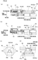
- FIG. 6(a) shows the yarn threading unit 33 viewed from above in the second direction.
- FIG. 6(b) shows the yarn threading unit 33 viewed from one side in the third direction.
- FIG. 6(c) shows the base end member 41a and its surroundings viewed from above in the second direction.
- FIG. 6(d) is a cross section taken along a line VId-VId in FIG. 6(c) .
- the cushion member 60 is provided to absorb external force applied to the yarn threading assisting member 47 provided in the yarn threading unit 33. As shown in FIG. 6(a) to FIG. 6(d) , the cushion member 60 includes the above-described extending member 61 (rotatable component of the present invention), a rotation shaft 62, and a torsion spring 63 (elastic member of the present invention).
- the extending member 61 extends in the first direction.
- the yarn threading assisting member 47 is attached to a leading end portion of the extending member 61.
- a base end portion (base end member 41a) in the first direction of the extending member 61 is, via the rotation shaft 62 extending in the second direction, attached to a lower part of an arm 32a which is at the leading end of the robotic arm 32. (Hereinafter, this arm 32a will be referred to as arm 64.)
- the rotation shaft 62 is, for example, fixed to the top surface of the base end member 41a and is rotatably attached to a lower end portion of the arm 64 (see FIG. 6(d) ). With this arrangement, when external force is applied, the extending member 61 is passively rotatable about the rotation shaft 62, with respect to the arm 64.
- the torsion spring 63 is provided to surround the rotation shaft 62 (i.e., the rotation center of the extending member 61). As shown in FIG. 6(d) , one end portion 63a of the torsion spring 63 extends upward in the second direction and is inserted into an insertion hole 65 which is formed in the bottom surface of the arm 64. The other end portion 63b of the torsion spring 63 extends downward in the second direction and is inserted into an insertion hole 66 formed in the upper surface of the base end member 41a.
- the torsion spring 63 is distorted and elastically deformed when the extending member 61 is passively rotated, and biases the extending member 61 and the yarn threading assisting member 47 toward the original positions, by the elastic restoring force.
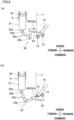
- FIG. 7(a) shows a change of the posture of the yarn threading assisting member 47.
- FIG. 7(b) shows the movement of the yarn threading assisting member 47 and the extending member 61 when external force is applied to the yarn threading assisting member 47.
- the extending member 61 is schematically shown in FIG. 7(a) and FIG. 7(b) .
- the assisting member rotation device 47 is switched by the assisting member rotation device 55 between an initial posture (see full lines in FIG. 7 (a) ) in which the yarn threading assisting member 47 is substantially parallel to the first direction and a yarn threading posture (see two-dot chain lines FIG. 7(a) ) in which the yarn threading assisting member 47 is substantially parallel to the third direction.
- the yarn threading assisting member 47 is rotatable about the rotation shaft 62, together with the extending member 61 (see two-dot chain lines in FIG. 7(b) ).
- the direction in which the extending member 61 rotates intersects with the direction in which the guide surface 29a extends when the assisting member guide unit 29 takes the guide posture (i.e., the guide direction).
- the direction in which the extending member 61 rotates will be referred to as an intersecting direction.
- the leading end portion of the yarn threading assisting member 47 is close to the guide surface 29a in the intersecting direction, whereas the base end portion of the yarn threading assisting member 47 is far from the guide surface 29a in the intersecting direction.
- a side close to the guide surface 29a i.e., guide surface 29a side
- a side far from the guide surface 29a will be referred to as the other side.
- the torsion spring 63 When external force is applied to the yarn threading assisting member 47 in the intersecting direction, the torsion spring 63 is distorted and hence the external force is absorbed. As the torsion spring 63 is distorted, elastic restoring force is generated and the yarn threading assisting member 47 is biased in the direction opposite to the rotated direction. In FIG. 7(b) , the yarn threading assisting member 47 is biased toward the one side (guide surface 29a side) in the intersecting direction when rotated toward the other side in the intersecting direction (see two-dot chain lines in FIG. 7(b) ).
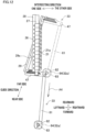
- FIG. 8(a), FIG. 8(b) , FIG. 9(a), FIG. 9(b) , and FIG. 10 Each of FIG. 8(a) and FIG. 8(b) illustrates yarn threading onto the first godet roller 12 and the second godet roller 13. Each of FIG. 9(a) and FIG. 9(b) shows an operation to cause the yarn threading assisting member 47 to hold yarns.
- FIG. 10 shows yarn threading to the fulcrum guides 21.
- the yarn threading to the fulcrum guides 21 is equivalent to yarn threading in the present invention.
- the yarn threading control unit 102 arranges the pressing roller 46 and the yarn threading assisting member 47 of the yarn threading unit 33 to take initial postures. Furthermore, the take-up unit controller 101 of the take-up unit 3 which is the target of the yarn threading controls the motor 113 (see FIG. 5 ) to move the second godet roller 13 along the guide rail 15, in order to position the second godet roller 13 to be close to the first godet roller 12 (see one-dot chain lines in FIG. 2 ). Furthermore, the take-up unit controller 101 drives the cylinder 114 (see FIG. 5 ) to gather the fulcrum guides 21 to the front side so that the fulcrum guides 21 are close to one another (see FIG. 3(b) ). Furthermore, the take-up unit controller 101 drives the cylinder 115 (see FIG. 5 ) to switch the posture of the assisting member guide unit 29 from the initial posture to the guide posture.
- the yarn threading control unit 102 then controls the main body moving device 121 to move the yarn threading robot 4 to a position overlapping, in the front-rear direction, the take-up unit 3 which is the target of the yarn threading. Subsequently, the yarn threading control unit 102 controls members such as the arm motor 122 and the suction 42 to cause the suction 42 to suck and hold the yarns Y spun out from the spinning apparatus. Furthermore, the yarn threading control unit 102 controls the arm motor 122 to drive the robotic arm 32 and move the yarn threading unit 33.
- the yarn threading control unit 102 moves the yarn threading unit 33 while maintaining the yarn threading unit 33 to take a posture with which the first direction is substantially parallel to the front-rear direction, the second direction is substantially parallel to the vertical direction, and the third direction is substantially parallel to the left-right direction.
- the yarn threading control unit 102 causes the yarn threading unit 33 to perform yarn threading to the first godet roller 12 (see FIG. 8(a) ), and then causes the yarn threading unit 33 to perform yarn threading to the second godet roller 13 (see FIG. 8(b) ).
- the yarn threading control unit 102 controls the roller rotation device 53 to switch the posture of the pressing roller 46 from the initial posture to the pressing posture (see two-dot chain lines in FIG. 9(a) ).
- the pressing roller 46 is pressed onto the yarns Y and rotates due to the friction force with the yarns Y.
- the intervals of the yarns Y are widened at the part onto which the pressing roller 46 is pressed, and the intervals of the yarns Y become substantially identical with the intervals of the opening portions of the grooves 47a of the yarn threading assisting member 47.
- the yarn threading control unit 102 drives the cylinder 51 to slide the slidable component 45 toward the leading end side in the first direction (see an arrow A1 in FIG. 9(a) ).
- the pressing roller 46 pressed onto the yarns Y slides toward the leading end side in the first direction together with the slidable component 45, so as to move away from the suction 42 (see full lines in FIG. 9(a) ). Consequently, the inclination angle of the yarns Y running from the pressing roller 46 toward the suction 42 is decreased relative to the first direction, with the result that differences between the positions where the yarns Y leave the pressing roller 46 are reduced and yarn shaking is suppressed.
- the yarn threading control unit 102 controls the assisting member rotation device 55 to switch the posture of the yarn threading assisting member 47 from the initial posture to the yarn threading posture (see an arrow A2 in FIG. 9(b) ).
- the grooves 47a of the yarn threading assisting member 47 face the respective yarns Y onto which the pressing roller 46 is pressed.
- the yarn threading control unit 102 controls the roller rotation device 53 to return the posture of the pressing roller 46 from the pressing posture to the initial posture.
- the pressing roller 46 moves away from the yarns Y, and the yarns Y are inserted into the respective grooves 47a. In this way, the yarns Y are temporarily held by the yarn threading assisting member 47.
- the yarn threading control unit 102 drives the robotic arm 32 to move the yarn threading assisting member 47 rearward.
- the yarn threading control unit 102 moves the yarn threading assisting member 47 to the rear side of the rearmost fulcrum guide 21 (i.e., to the far side of the farthest fulcrum guide 21 in the guide direction).
- the yarn threading control unit 102 drives the robotic arm 32 to cause the leading end portion of the yarn threading assisting member 47 to make contact with the guide surface 29a of the assisting member guide unit 29 (see two-dot chain lines in FIG. 10 ).
- the elastic restoring force generated in the torsion spring 63 biases the extending member 61 and the yarn threading assisting member 47 toward the one side (guide surface 29a side) in the intersecting direction. This causes the yarn threading assisting member 47 to reliably make contact with the guide surface 29a.
- the yarn threading control unit 102 drives the robotic arm 32 to move the yarn threading unit 33 at least toward the near side in the guide direction (see full lines and an arrow A3 in FIG. 10 ) while maintaining the yarn threading assisting member 47 to be always in contact with the guide surface 29a.
- the yarns Y inserted into the grooves 47a are threaded to the corresponding fulcrum guides 21, respectively (yarn threading).
- the direction in which the yarn threading unit 33 is moved is most preferably substantially parallel to the guide direction.
- the direction in which the yarn threading unit 33 is moved is not limited to this direction.
- the direction in which the yarn threading unit 33 is moved may be tilted leftward or rightward with respect to the guide direction.
- the yarn threading control unit 102 may move the arm 64 linearly rearward in the direction parallel to the front-rear direction.
- the yarn threading control unit 102 may arrange the moving distance of the arm 64 in the intersecting direction to be shorter than the required moving distance of the yarn threading assisting member 47 in the intersecting direction.
- the yarn threading assisting member 47 is controlled to be always in contact with the guide surface 29a while yarn threading to the fulcrum guides 21 is being performed.
- the yarns Y are threaded to the corresponding fulcrum guides 21 even if the moving direction of the yarn threading unit 33 is not rigorously controlled as compared to the case where the assisting member guide unit 29 is not provided.
- the take-up unit controller 101 moves the second godet roller 13 and the fulcrum guides 21 to the positions for the winding. Furthermore, the yarn threading control unit 102 returns the posture of the yarn threading assisting member 47 from the yarn threading posture to the initial posture.
- FIG. 11 is a flowchart showing the steps of the teaching.
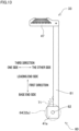
- FIG. 12 shows the movement of the yarn threading unit 33 during the teaching.
- an operator performs the teaching by operating the teaching pendant 103 (see FIG. 5 ). It is assumed that teaching for the yarn threading to the first godet roller 12 and the second godet roller 13 has already been done. In the present embodiment, the operator performs the teaching in a state in which the yarn threading assisting member 47 does not hold the yarns Y.
- the operator operates the teaching pendant 103 to provisionally set a start position and an end position of yarn threading to the fulcrum guides 21 of a take-up unit 3 (S101).
- the start position is, for example, the position of the leading end portion of the extending member 61 (see FIG. 12 ) at the start of the yarn threading to the fulcrum guides 21.
- the end position is, for example, the position of the leading end portion of the extending member 61 at the end of the yarn threading.
- information regarding the positions of another member such as the arm 64 may be input to the teaching pendant 103, as the start position and the end position.
- the operator operates the teaching pendant 103 to check the operation of the yarn threading robot 4, while the yarn threading assisting member 47 does not hold the yarns Y (S102).
- the yarn threading robot 4 is actually driven (see an arrow A4 in FIG. 12 ).
- the operator checks, visually for example, whether the yarn threading assisting member 47 is always in contact with the guide surface 29a from the start to the end of the operation (S103).
- the operator operates the teaching pendant 103 to cause the storage unit 102a of the yarn threading control unit 102 to store information (operation information) regarding the start position and the end position (S104). In this way, the operation information is stored so that the contact between the yarn threading assisting member 47 and the guide surface 29a is maintained from the start to the end of the yarn threading.
- the operator When the yarn threading assisting member 47 is detached from the guide surface 29a during the time from the start to the end of the operation (No in S103), the operator returns to the step S101 and performs the provisional setting of the start position and the end position again. Also in this case, the information regarding the start position and the end position can be easily corrected by visually recognizing the distance between the leading end portion of the yarn threading assisting member 47 and the guide surface 29a during the operation check.
- the operation information stored in the yarn threading control unit 102 may be (duplicated and) used for yarn threading in another take-up unit 3.
- the relative positions of the yarn threading robot 4 and the fulcrum guides 21 may be slightly different between the take-up units 3.
- the present embodiment only requires that the contact between the yarn threading assisting member 47 and the guide surface 29a is maintained from the start to the end of the yarn threading. The number of times of the teaching is therefore reduced, and the time required for the teaching is further shortened.
- the cushion member 60 absorbs the repellent force from the guide surface 29a to the yarn threading assisting member 47. It is therefore possible to suppress the application of excessive force to the yarn threading assisting member 47, when the yarn threading assisting member 47 of the yarn threading robot 4 is in contact with the assisting member guide unit 29.
- the yarn threading assisting member 47 is biased toward the guide surface 29a side by the torsion spring 63 during the yarn threading, the yarn threading assisting member 47 is actively made contact with the guide surface 29a within a range of elastic deformation of the torsion spring 63. It is therefore possible to easily make the yarn threading assisting member 47 in contact with the guide surface 29a, without needing rigorous position control of the yarn threading assisting member 47.
- the extending member 61 which is rotatable and to which the yarn threading assisting member 47 is attached is biased, the movable range of the yarn threading assisting member 47 is widened as the yarn threading assisting member 47 is attached to the leading end portion of the extending member 61 as in the present embodiment.
- the extending member 61 is biased with a simple arrangement using the torsion spring 63.
- the biasing force is therefore easily adjustable.
- the moving path of the yarn threading assisting member 47 is determined in advance by the guide surface 29a of the assisting member guide unit 29, the number of times of the operation check is significantly reduced as compared to cases where the yarn threading is performed without using the assisting member guide unit 29.
- the time required for the teaching is therefore significantly shortened.
- the yarn threading assisting member 47 moves along the guide surface 29a. It is therefore possible to perform correct teaching even when the yarn threading assisting member 47 does not hold the yarns. Because it is unnecessary to cause the yarn threading assisting member 47 to hold the yarns Y during the teaching, the time required for the teaching is dramatically shortened.
Landscapes
- Engineering & Computer Science (AREA)
- Mechanical Engineering (AREA)
- Textile Engineering (AREA)
- Spinning Methods And Devices For Manufacturing Artificial Fibers (AREA)
- Guides For Winding Or Rewinding, Or Guides For Filamentary Materials (AREA)
Applications Claiming Priority (1)
| Application Number | Priority Date | Filing Date | Title |
|---|---|---|---|
| JP2019049445A JP7263070B2 (ja) | 2019-03-18 | 2019-03-18 | 繊維機械、及びティーチング方法 |
Publications (2)
| Publication Number | Publication Date |
|---|---|
| EP3712097A1 EP3712097A1 (en) | 2020-09-23 |
| EP3712097B1 true EP3712097B1 (en) | 2023-02-15 |
Family
ID=69770607
Family Applications (1)
| Application Number | Title | Priority Date | Filing Date |
|---|---|---|---|
| EP20160905.4A Active EP3712097B1 (en) | 2019-03-18 | 2020-03-04 | Textile machine and teaching method |
Country Status (4)
| Country | Link |
|---|---|
| EP (1) | EP3712097B1 (zh) |
| JP (1) | JP7263070B2 (zh) |
| CN (1) | CN111705371B (zh) |
| TW (1) | TWI794594B (zh) |
Families Citing this family (2)
| Publication number | Priority date | Publication date | Assignee | Title |
|---|---|---|---|---|
| JP2023091957A (ja) * | 2021-12-21 | 2023-07-03 | Tmtマシナリー株式会社 | 糸巻取機 |
| JP2024138941A (ja) * | 2023-03-27 | 2024-10-09 | Tmtマシナリー株式会社 | 糸巻取機 |
Family Cites Families (14)
| Publication number | Priority date | Publication date | Assignee | Title |
|---|---|---|---|---|
| JPS5361736A (en) * | 1976-11-10 | 1978-06-02 | Mitsubishi Heavy Ind Ltd | Device for traversing high speed winder |
| JPS5383727U (zh) * | 1976-12-07 | 1978-07-11 | ||
| JPS5848284Y2 (ja) * | 1976-12-16 | 1983-11-04 | 東レエンジニアリング株式会社 | 巻取装置 |
| JPS6116291Y2 (zh) * | 1981-04-20 | 1986-05-20 | ||
| DE102004044786A1 (de) * | 2004-09-16 | 2006-04-06 | Saurer Gmbh & Co. Kg | Vorrichtung und Verfahren zum Ablegen eines Spinnkabels |
| CN201321052Y (zh) * | 2008-12-23 | 2009-10-07 | 中国北车集团大同电力机车有限责任公司 | 具有自恢复力的车钩缓冲装置 |
| JP5615743B2 (ja) | 2011-03-11 | 2014-10-29 | Tmtマシナリー株式会社 | 紡糸巻取機 |
| JP6153791B2 (ja) * | 2013-07-03 | 2017-06-28 | Tmtマシナリー株式会社 | 紡糸引取機、及び、紡糸引取方法 |
| JP6393206B2 (ja) | 2014-02-05 | 2018-09-19 | Tmtマシナリー株式会社 | 糸巻取機 |
| CN104354158A (zh) * | 2014-10-31 | 2015-02-18 | 桐乡市洲泉纺织五金加弹厂 | 一种自动挂丝机械手 |
| CN204223962U (zh) * | 2014-11-13 | 2015-03-25 | 杭州华水布艺有限公司 | 纱线张力器 |
| JP6756573B2 (ja) | 2015-10-30 | 2020-09-16 | Tmtマシナリー株式会社 | 自動糸掛け装置 |
| JP6829044B2 (ja) * | 2016-10-20 | 2021-02-10 | Tmtマシナリー株式会社 | 糸掛けロボット |
| JP6966230B2 (ja) * | 2017-06-15 | 2021-11-10 | Tmtマシナリー株式会社 | 自動糸掛け装置、糸処理設備、及び、糸掛け方法 |
-
2019
- 2019-03-18 JP JP2019049445A patent/JP7263070B2/ja active Active
-
2020
- 2020-03-04 EP EP20160905.4A patent/EP3712097B1/en active Active
- 2020-03-09 TW TW109107588A patent/TWI794594B/zh active
- 2020-03-10 CN CN202010161012.8A patent/CN111705371B/zh active Active
Also Published As
| Publication number | Publication date |
|---|---|
| EP3712097A1 (en) | 2020-09-23 |
| TWI794594B (zh) | 2023-03-01 |
| TW202035267A (zh) | 2020-10-01 |
| CN111705371B (zh) | 2023-04-04 |
| JP7263070B2 (ja) | 2023-04-24 |
| CN111705371A (zh) | 2020-09-25 |
| JP2020153020A (ja) | 2020-09-24 |
Similar Documents
| Publication | Publication Date | Title |
|---|---|---|
| EP3162749B1 (en) | Automatic yarn threading device | |
| EP3838824B1 (en) | Yarn threading robot | |
| EP3712097B1 (en) | Textile machine and teaching method | |
| JP6393206B2 (ja) | 糸巻取機 | |
| EP3415452B1 (en) | Automatic yarn threading device, yarn processing system, and yarn threading method | |
| JP2009519188A (ja) | 巻取機 | |
| EP3357847B1 (en) | Yarn winder, spun yarn take-up apparatus, and a method of yarn threading in yarn winder | |
| EP2078691A2 (en) | Kink preventing device and automatic winder comprising the same | |
| JP7286385B2 (ja) | 繊維機械 | |
| CN111470382B (zh) | 接纱装置及纱线卷绕装置 | |
| EP3871862A1 (en) | Automated fiber bundle placement apparatus | |
| EP3006384B1 (en) | Bobbin separating device, doffing cart, and yarn winding machine | |
| EP4292967A1 (en) | Holding method, yarn supply device and yarn supply stand | |
| EP4378868A1 (en) | Yarn winder | |
| CN113825714B (zh) | 线条体的卷绕装置及线条体的卷绕方法 | |
| CN107630311B (zh) | 自动上经纱轴装置及浆纱机构 | |
| CN113293471A (zh) | 自动纱线捻接单元 | |
| TW201918600A (zh) | 劍桿織機的投緯裝置 |
Legal Events
| Date | Code | Title | Description |
|---|---|---|---|
| PUAI | Public reference made under article 153(3) epc to a published international application that has entered the european phase |
Free format text: ORIGINAL CODE: 0009012 |
|
| STAA | Information on the status of an ep patent application or granted ep patent |
Free format text: STATUS: THE APPLICATION HAS BEEN PUBLISHED |
|
| AK | Designated contracting states |
Kind code of ref document: A1 Designated state(s): AL AT BE BG CH CY CZ DE DK EE ES FI FR GB GR HR HU IE IS IT LI LT LU LV MC MK MT NL NO PL PT RO RS SE SI SK SM TR |
|
| AX | Request for extension of the european patent |
Extension state: BA ME |
|
| STAA | Information on the status of an ep patent application or granted ep patent |
Free format text: STATUS: REQUEST FOR EXAMINATION WAS MADE |
|
| 17P | Request for examination filed |
Effective date: 20201208 |
|
| RBV | Designated contracting states (corrected) |
Designated state(s): AL AT BE BG CH CY CZ DE DK EE ES FI FR GB GR HR HU IE IS IT LI LT LU LV MC MK MT NL NO PL PT RO RS SE SI SK SM TR |
|
| GRAP | Despatch of communication of intention to grant a patent |
Free format text: ORIGINAL CODE: EPIDOSNIGR1 |
|
| STAA | Information on the status of an ep patent application or granted ep patent |
Free format text: STATUS: GRANT OF PATENT IS INTENDED |
|
| INTG | Intention to grant announced |
Effective date: 20220926 |
|
| GRAS | Grant fee paid |
Free format text: ORIGINAL CODE: EPIDOSNIGR3 |
|
| GRAA | (expected) grant |
Free format text: ORIGINAL CODE: 0009210 |
|
| STAA | Information on the status of an ep patent application or granted ep patent |
Free format text: STATUS: THE PATENT HAS BEEN GRANTED |
|
| AK | Designated contracting states |
Kind code of ref document: B1 Designated state(s): AL AT BE BG CH CY CZ DE DK EE ES FI FR GB GR HR HU IE IS IT LI LT LU LV MC MK MT NL NO PL PT RO RS SE SI SK SM TR |
|
| REG | Reference to a national code |
Ref country code: CH Ref legal event code: EP Ref country code: GB Ref legal event code: FG4D |
|
| REG | Reference to a national code |
Ref country code: DE Ref legal event code: R096 Ref document number: 602020008014 Country of ref document: DE |
|
| REG | Reference to a national code |
Ref country code: AT Ref legal event code: REF Ref document number: 1548150 Country of ref document: AT Kind code of ref document: T Effective date: 20230315 Ref country code: IE Ref legal event code: FG4D |
|
| REG | Reference to a national code |
Ref country code: LT Ref legal event code: MG9D |
|
| P01 | Opt-out of the competence of the unified patent court (upc) registered |
Effective date: 20230426 |
|
| REG | Reference to a national code |
Ref country code: NL Ref legal event code: MP Effective date: 20230215 |
|
| REG | Reference to a national code |
Ref country code: AT Ref legal event code: MK05 Ref document number: 1548150 Country of ref document: AT Kind code of ref document: T Effective date: 20230215 |
|
| PG25 | Lapsed in a contracting state [announced via postgrant information from national office to epo] |
Ref country code: RS Free format text: LAPSE BECAUSE OF FAILURE TO SUBMIT A TRANSLATION OF THE DESCRIPTION OR TO PAY THE FEE WITHIN THE PRESCRIBED TIME-LIMIT Effective date: 20230215 Ref country code: PT Free format text: LAPSE BECAUSE OF FAILURE TO SUBMIT A TRANSLATION OF THE DESCRIPTION OR TO PAY THE FEE WITHIN THE PRESCRIBED TIME-LIMIT Effective date: 20230615 Ref country code: NO Free format text: LAPSE BECAUSE OF FAILURE TO SUBMIT A TRANSLATION OF THE DESCRIPTION OR TO PAY THE FEE WITHIN THE PRESCRIBED TIME-LIMIT Effective date: 20230515 Ref country code: NL Free format text: LAPSE BECAUSE OF FAILURE TO SUBMIT A TRANSLATION OF THE DESCRIPTION OR TO PAY THE FEE WITHIN THE PRESCRIBED TIME-LIMIT Effective date: 20230215 Ref country code: LV Free format text: LAPSE BECAUSE OF FAILURE TO SUBMIT A TRANSLATION OF THE DESCRIPTION OR TO PAY THE FEE WITHIN THE PRESCRIBED TIME-LIMIT Effective date: 20230215 Ref country code: LT Free format text: LAPSE BECAUSE OF FAILURE TO SUBMIT A TRANSLATION OF THE DESCRIPTION OR TO PAY THE FEE WITHIN THE PRESCRIBED TIME-LIMIT Effective date: 20230215 Ref country code: HR Free format text: LAPSE BECAUSE OF FAILURE TO SUBMIT A TRANSLATION OF THE DESCRIPTION OR TO PAY THE FEE WITHIN THE PRESCRIBED TIME-LIMIT Effective date: 20230215 Ref country code: ES Free format text: LAPSE BECAUSE OF FAILURE TO SUBMIT A TRANSLATION OF THE DESCRIPTION OR TO PAY THE FEE WITHIN THE PRESCRIBED TIME-LIMIT Effective date: 20230215 Ref country code: AT Free format text: LAPSE BECAUSE OF FAILURE TO SUBMIT A TRANSLATION OF THE DESCRIPTION OR TO PAY THE FEE WITHIN THE PRESCRIBED TIME-LIMIT Effective date: 20230215 |
|
| PG25 | Lapsed in a contracting state [announced via postgrant information from national office to epo] |
Ref country code: SE Free format text: LAPSE BECAUSE OF FAILURE TO SUBMIT A TRANSLATION OF THE DESCRIPTION OR TO PAY THE FEE WITHIN THE PRESCRIBED TIME-LIMIT Effective date: 20230215 Ref country code: PL Free format text: LAPSE BECAUSE OF FAILURE TO SUBMIT A TRANSLATION OF THE DESCRIPTION OR TO PAY THE FEE WITHIN THE PRESCRIBED TIME-LIMIT Effective date: 20230215 Ref country code: IS Free format text: LAPSE BECAUSE OF FAILURE TO SUBMIT A TRANSLATION OF THE DESCRIPTION OR TO PAY THE FEE WITHIN THE PRESCRIBED TIME-LIMIT Effective date: 20230615 Ref country code: GR Free format text: LAPSE BECAUSE OF FAILURE TO SUBMIT A TRANSLATION OF THE DESCRIPTION OR TO PAY THE FEE WITHIN THE PRESCRIBED TIME-LIMIT Effective date: 20230516 Ref country code: FI Free format text: LAPSE BECAUSE OF FAILURE TO SUBMIT A TRANSLATION OF THE DESCRIPTION OR TO PAY THE FEE WITHIN THE PRESCRIBED TIME-LIMIT Effective date: 20230215 |
|
| PG25 | Lapsed in a contracting state [announced via postgrant information from national office to epo] |
Ref country code: SM Free format text: LAPSE BECAUSE OF FAILURE TO SUBMIT A TRANSLATION OF THE DESCRIPTION OR TO PAY THE FEE WITHIN THE PRESCRIBED TIME-LIMIT Effective date: 20230215 Ref country code: RO Free format text: LAPSE BECAUSE OF FAILURE TO SUBMIT A TRANSLATION OF THE DESCRIPTION OR TO PAY THE FEE WITHIN THE PRESCRIBED TIME-LIMIT Effective date: 20230215 Ref country code: EE Free format text: LAPSE BECAUSE OF FAILURE TO SUBMIT A TRANSLATION OF THE DESCRIPTION OR TO PAY THE FEE WITHIN THE PRESCRIBED TIME-LIMIT Effective date: 20230215 Ref country code: DK Free format text: LAPSE BECAUSE OF FAILURE TO SUBMIT A TRANSLATION OF THE DESCRIPTION OR TO PAY THE FEE WITHIN THE PRESCRIBED TIME-LIMIT Effective date: 20230215 Ref country code: CZ Free format text: LAPSE BECAUSE OF FAILURE TO SUBMIT A TRANSLATION OF THE DESCRIPTION OR TO PAY THE FEE WITHIN THE PRESCRIBED TIME-LIMIT Effective date: 20230215 |
|
| REG | Reference to a national code |
Ref country code: CH Ref legal event code: PL |
|
| REG | Reference to a national code |
Ref country code: DE Ref legal event code: R097 Ref document number: 602020008014 Country of ref document: DE |
|
| PG25 | Lapsed in a contracting state [announced via postgrant information from national office to epo] |
Ref country code: SK Free format text: LAPSE BECAUSE OF FAILURE TO SUBMIT A TRANSLATION OF THE DESCRIPTION OR TO PAY THE FEE WITHIN THE PRESCRIBED TIME-LIMIT Effective date: 20230215 |
|
| REG | Reference to a national code |
Ref country code: BE Ref legal event code: MM Effective date: 20230331 |
|
| PLBE | No opposition filed within time limit |
Free format text: ORIGINAL CODE: 0009261 |
|
| STAA | Information on the status of an ep patent application or granted ep patent |
Free format text: STATUS: NO OPPOSITION FILED WITHIN TIME LIMIT |
|
| PG25 | Lapsed in a contracting state [announced via postgrant information from national office to epo] |
Ref country code: LU Free format text: LAPSE BECAUSE OF NON-PAYMENT OF DUE FEES Effective date: 20230304 |
|
| PG25 | Lapsed in a contracting state [announced via postgrant information from national office to epo] |
Ref country code: MC Free format text: LAPSE BECAUSE OF FAILURE TO SUBMIT A TRANSLATION OF THE DESCRIPTION OR TO PAY THE FEE WITHIN THE PRESCRIBED TIME-LIMIT Effective date: 20230215 |
|
| REG | Reference to a national code |
Ref country code: IE Ref legal event code: MM4A |
|
| 26N | No opposition filed |
Effective date: 20231116 |
|
| PG25 | Lapsed in a contracting state [announced via postgrant information from national office to epo] |
Ref country code: SI Free format text: LAPSE BECAUSE OF FAILURE TO SUBMIT A TRANSLATION OF THE DESCRIPTION OR TO PAY THE FEE WITHIN THE PRESCRIBED TIME-LIMIT Effective date: 20230215 Ref country code: MC Free format text: LAPSE BECAUSE OF FAILURE TO SUBMIT A TRANSLATION OF THE DESCRIPTION OR TO PAY THE FEE WITHIN THE PRESCRIBED TIME-LIMIT Effective date: 20230215 Ref country code: LI Free format text: LAPSE BECAUSE OF NON-PAYMENT OF DUE FEES Effective date: 20230331 Ref country code: IE Free format text: LAPSE BECAUSE OF NON-PAYMENT OF DUE FEES Effective date: 20230304 Ref country code: FR Free format text: LAPSE BECAUSE OF NON-PAYMENT OF DUE FEES Effective date: 20230415 Ref country code: CH Free format text: LAPSE BECAUSE OF NON-PAYMENT OF DUE FEES Effective date: 20230331 |
|
| PG25 | Lapsed in a contracting state [announced via postgrant information from national office to epo] |
Ref country code: BE Free format text: LAPSE BECAUSE OF NON-PAYMENT OF DUE FEES Effective date: 20230331 |
|
| PGFP | Annual fee paid to national office [announced via postgrant information from national office to epo] |
Ref country code: DE Payment date: 20240320 Year of fee payment: 5 |
|
| PGFP | Annual fee paid to national office [announced via postgrant information from national office to epo] |
Ref country code: IT Payment date: 20240320 Year of fee payment: 5 |