EP3709898B1 - Clip und clip-anordnung - Google Patents
Clip und clip-anordnung Download PDFInfo
- Publication number
- EP3709898B1 EP3709898B1 EP18812575.1A EP18812575A EP3709898B1 EP 3709898 B1 EP3709898 B1 EP 3709898B1 EP 18812575 A EP18812575 A EP 18812575A EP 3709898 B1 EP3709898 B1 EP 3709898B1
- Authority
- EP
- European Patent Office
- Prior art keywords
- clip
- release portion
- jaws
- endoscopic device
- assembly
- Prior art date
- Legal status (The legal status is an assumption and is not a legal conclusion. Google has not performed a legal analysis and makes no representation as to the accuracy of the status listed.)
- Active
Links
- 239000000696 magnetic material Substances 0.000 claims description 4
- 230000014759 maintenance of location Effects 0.000 description 46
- 230000007246 mechanism Effects 0.000 description 25
- 230000002439 hemostatic effect Effects 0.000 description 9
- 238000000034 method Methods 0.000 description 6
- 239000000463 material Substances 0.000 description 5
- 239000002184 metal Substances 0.000 description 5
- 229910052751 metal Inorganic materials 0.000 description 5
- 238000001574 biopsy Methods 0.000 description 4
- 230000036316 preload Effects 0.000 description 4
- 230000000717 retained effect Effects 0.000 description 4
- 230000000740 bleeding effect Effects 0.000 description 3
- 230000000694 effects Effects 0.000 description 3
- 238000004873 anchoring Methods 0.000 description 2
- 230000002457 bidirectional effect Effects 0.000 description 2
- 230000009977 dual effect Effects 0.000 description 2
- 238000005259 measurement Methods 0.000 description 2
- 229920003023 plastic Polymers 0.000 description 2
- 239000004033 plastic Substances 0.000 description 2
- 230000000087 stabilizing effect Effects 0.000 description 2
- 206010059875 Device ineffective Diseases 0.000 description 1
- 206010013530 Diverticula Diseases 0.000 description 1
- 206010013554 Diverticulum Diseases 0.000 description 1
- 208000025865 Ulcer Diseases 0.000 description 1
- 208000027418 Wounds and injury Diseases 0.000 description 1
- 230000003044 adaptive effect Effects 0.000 description 1
- 210000001367 artery Anatomy 0.000 description 1
- 230000000712 assembly Effects 0.000 description 1
- 238000000429 assembly Methods 0.000 description 1
- 239000000919 ceramic Substances 0.000 description 1
- 210000001072 colon Anatomy 0.000 description 1
- 230000007547 defect Effects 0.000 description 1
- 230000003111 delayed effect Effects 0.000 description 1
- 238000002059 diagnostic imaging Methods 0.000 description 1
- 229910003460 diamond Inorganic materials 0.000 description 1
- 239000010432 diamond Substances 0.000 description 1
- 239000012636 effector Substances 0.000 description 1
- 239000013013 elastic material Substances 0.000 description 1
- 238000005516 engineering process Methods 0.000 description 1
- 210000003238 esophagus Anatomy 0.000 description 1
- -1 ferrous metals Chemical class 0.000 description 1
- 238000007667 floating Methods 0.000 description 1
- 210000001035 gastrointestinal tract Anatomy 0.000 description 1
- 239000011521 glass Substances 0.000 description 1
- 230000023597 hemostasis Effects 0.000 description 1
- 230000003993 interaction Effects 0.000 description 1
- 230000002452 interceptive effect Effects 0.000 description 1
- 230000003902 lesion Effects 0.000 description 1
- 230000033001 locomotion Effects 0.000 description 1
- 238000012986 modification Methods 0.000 description 1
- 230000004048 modification Effects 0.000 description 1
- 230000008569 process Effects 0.000 description 1
- 230000000069 prophylactic effect Effects 0.000 description 1
- 238000002271 resection Methods 0.000 description 1
- 230000007480 spreading Effects 0.000 description 1
- 230000000153 supplemental effect Effects 0.000 description 1
- 231100000397 ulcer Toxicity 0.000 description 1
Images


Classifications
-
- A—HUMAN NECESSITIES
- A61—MEDICAL OR VETERINARY SCIENCE; HYGIENE
- A61B—DIAGNOSIS; SURGERY; IDENTIFICATION
- A61B17/00—Surgical instruments, devices or methods, e.g. tourniquets
- A61B17/12—Surgical instruments, devices or methods, e.g. tourniquets for ligaturing or otherwise compressing tubular parts of the body, e.g. blood vessels, umbilical cord
- A61B17/122—Clamps or clips, e.g. for the umbilical cord
-
- A—HUMAN NECESSITIES
- A61—MEDICAL OR VETERINARY SCIENCE; HYGIENE
- A61B—DIAGNOSIS; SURGERY; IDENTIFICATION
- A61B17/00—Surgical instruments, devices or methods, e.g. tourniquets
- A61B17/12—Surgical instruments, devices or methods, e.g. tourniquets for ligaturing or otherwise compressing tubular parts of the body, e.g. blood vessels, umbilical cord
- A61B17/128—Surgical instruments, devices or methods, e.g. tourniquets for ligaturing or otherwise compressing tubular parts of the body, e.g. blood vessels, umbilical cord for applying or removing clamps or clips
- A61B17/1285—Surgical instruments, devices or methods, e.g. tourniquets for ligaturing or otherwise compressing tubular parts of the body, e.g. blood vessels, umbilical cord for applying or removing clamps or clips for minimally invasive surgery
-
- A—HUMAN NECESSITIES
- A61—MEDICAL OR VETERINARY SCIENCE; HYGIENE
- A61B—DIAGNOSIS; SURGERY; IDENTIFICATION
- A61B17/00—Surgical instruments, devices or methods, e.g. tourniquets
- A61B17/00234—Surgical instruments, devices or methods, e.g. tourniquets for minimally invasive surgery
-
- A—HUMAN NECESSITIES
- A61—MEDICAL OR VETERINARY SCIENCE; HYGIENE
- A61B—DIAGNOSIS; SURGERY; IDENTIFICATION
- A61B17/00—Surgical instruments, devices or methods, e.g. tourniquets
- A61B2017/00477—Coupling
-
- A—HUMAN NECESSITIES
- A61—MEDICAL OR VETERINARY SCIENCE; HYGIENE
- A61B—DIAGNOSIS; SURGERY; IDENTIFICATION
- A61B17/00—Surgical instruments, devices or methods, e.g. tourniquets
- A61B17/12—Surgical instruments, devices or methods, e.g. tourniquets for ligaturing or otherwise compressing tubular parts of the body, e.g. blood vessels, umbilical cord
- A61B2017/12004—Surgical instruments, devices or methods, e.g. tourniquets for ligaturing or otherwise compressing tubular parts of the body, e.g. blood vessels, umbilical cord for haemostasis, for prevention of bleeding
-
- A—HUMAN NECESSITIES
- A61—MEDICAL OR VETERINARY SCIENCE; HYGIENE
- A61B—DIAGNOSIS; SURGERY; IDENTIFICATION
- A61B17/00—Surgical instruments, devices or methods, e.g. tourniquets
- A61B17/12—Surgical instruments, devices or methods, e.g. tourniquets for ligaturing or otherwise compressing tubular parts of the body, e.g. blood vessels, umbilical cord
- A61B17/12022—Occluding by internal devices, e.g. balloons or releasable wires
- A61B2017/1205—Introduction devices
Definitions
- Hemostatic clips are used to clamp or close tissue, vessels or ducts. They are generally used to control bleeding of tissue, vessel or ducts instead of suturing or stapling. Hemostatic clips, on the market are deemed “MR Conditional” per ASTM F2503-13, which can lead to clip failure during an MRI procedure. Under FDA guidance and ASTM F2503-13, "MR Safe” means that the item poses no known hazards in all MRI environments. An MR Safe clip will be stable in patients undergoing MRI and poses no known hazards in MRI environments. Document EP1993452 discloses an endoscopic device according to the preamble of claim 1.
- the present application describes a clip, comprising: a grab portion at a distal end of the clip, and a release portion at a proximal end of the clip.
- the clip is made of electrically nonconductive or non-magnetic material.
- the novel aspects of this device center around the fact that the clip can grasp and hold the tissue while residing in the body being subjected to a MRI procedure.
- the other clips on the market react under the induced magnetic field and this reaction (which can include vibration and/or temperature increase) which can compromise the retention ability of the clip. Utilizing materials that are not influenced by the high-energy magnetic field (such as plastics, glass, ceramics or non-ferrous metals), alleviate this concern.
- the present application further describes a clip assembly, comprising a clip and a locking mechanism.
- the clip includes a first arm at a distal end of the clip, a second arm at the distal end of the clip, and a release portion at a proximal end of the clip. At least one of the first and second arms is movable between an open position and a closed position. The distal end of each arm has an engagement portion.
- the clip is made of electrically nonconductive or non-magnetic material.
- the locking mechanism is configured to lock the first and second arms in the closed position.
- the present application further describes a method for applying a clip to a patient, comprising 1) expose the clip at its open position; 2) adjust the driver to align the engagement portions to a treatment area; 3) clip retracts into outer sheath to close the clip; 4) push the pusher tube to move the collar past the retention mechanism; 5) extend the driver out and retract the pusher tube back; 6) release the driver from the clip.
- the clip could be used for placement in the gastrointestinal tract for endoscopic marking; hemostasis for: mucosal/submucosal defects less than about 3 cm, bleeding ulcers, arteries less than about 2mm, polyps less than about 1.5cm in diameter, diverticula in the colon; prophylactic clipping to reduce the risk of delayed bleeding post lesion resection; anchoring to affix jejunal feeding tubes to the wall of the small bowel; anchoring to affix fully covered esophageal self-expanding metal stents to the wall of the esophagus; and as a supplemental closure method of luminal perforations less than about 20 mm that can be treated conservatively.
- the present subject matter describes a clip assembly and its driving assembly.
- the clip assembly comprises a clip 10 and a locking mechanism, such as a collar 20.
- the driving assembly 30 is configured to operate and release the clip assembly as desired.
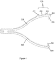
- the exemplary clip 10 comprises a grab portion 12 at a distal end of the clip 10 and a release portion 14 at a proximal end of the clip 10.
- the grab portion 12 comprises a first arm 50 and a second arm 60.
- one of the first and second arms 50, 60 is configured to be movable; the other arm is stationary.
- both the first and second arms 50, 60 are configured to be movable.
- one of the first and second arms 50, 60 is an elastic curved arm.
- both the first and second arms 50, 60 are elastic curved arms. A portion of the arm is convex outward from the axis of the clip.
- the clip has a wishbone shape, which allows a quick closure around tissue.
- the curved arms create an entrapment space for gathering tissue.
- the clip 10 may comprise more than two arms, such as three arms or four arms. In some embodiments, the clip has even number of arms.
- the arms could be planar. The arms could also be non-planar.
- the clip 10 has at least an 11 mm jaw opening at the open position. In some embodiments, the clip 10 may fit in, rotate and move through a scope with 2.8 mm channel at the closed position.
- a distal end 54 of the first arm 50 comprises a first engagement portion 56.
- a distal end 64 of the second arm 60 comprises a second engagement portion 66.
- the first or second engagement portions 56 or 66 is an offset tooth.
- the offset teeth have a profile in which the width of the distal engagement portions are wider than the arms of the clip to allow for superior grip on tissue.
- These engagement portions may be made of alternative materials and attached to the arms.
- the first and second engagement portions 56, 66 may be multiple offset teeth, or other known structures that may stably engage each other in order to achieve effective hemostatic effects.
- the first and second engagement portions comprise dual offset teeth. The dual teeth structure prevents the offset teeth from overlapping too much and becoming stuck in a closed position.
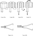
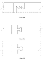
- At least one arm comprises a retention mechanism 16.
- the retention mechanism 16 comprises a retention fin 57 disposed near the distal end 54 of the first arm 50.
- the retention fin 57 allows the collar 20 to move from the proximal end of the clip 10 towards the distal end of the clip.
- the retention fin 57 may contain a negative angle or other geometry such that interfacing with geometry of collar 20 prevents the collar 20 from sliding away from the distal end 54 of the first arm 50 so as to keep the clip 10 at the closed position and the first and second engagement portions 56, 66 engaged.
- the retention mechanism 116 comprises a first retention fin 157 disposed near the first distal end 154 of the first arm 150 and a second retention fin 167 disposed near the second distal end 164 of the second arm 160.
- the first and second retention fins 157, 167 have similar function as the retention fin 57 described above.
- the retention mechanism 216 comprises a retention fin 257, a distal stop 258, and a recess 259 between the retention fin 257 and the distal stop 258.
- the retention fin 257, the distal stop 258, and the recess 259 are disposed near the distal end 254 of the first arm 250.
- the retention fin 257 has similar function as the retention fin 57 described above.
- the length of the recess 259 is configured to receive the collar 20.
- the distal stop 258 prevents the collar 20 from sliding out of the distal ends 254, 264 of the first and second arms 250, 260.
- the retention mechanism 316 comprises first and second retention fin 357, 367, first and second distal stops 358, 368, a first recess 359 between the first retention fin 357 and the first distal stop 358, and a second recess 369 between the second retention fin 367 and the second distal stop 368.
- the length of the first and second recesses 359, 369 are configured to receive the collar 20.
- the first and second retention fins 357, 367 have similar function as the retention fin 57 described above.
- the first and second distal stops 358, 368 have similar function as the distal stop 158 described above.
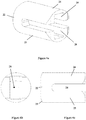
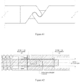
- the collar 20 comprises a sleeve 22 and a guide channel 28 at the center of the sleeve 22.
- the arms 50, 60 of clip 10 are able to pass through the guide channel 28 so that the collar 20 is able to move along the arms 50, 60 of clip 10.
- the guide channel 28 has a height H and a width W.
- the height H of the guide channel 28 is equal to or slightly higher than a height H' of the retention fin 57 portion of the clip 10 at a closed position.
- the width W of the guide channel 28 is equal to or slightly wider than a width W' of the clip 10.
- the guide channel 28 is configured to enable the collar 20 to pass over and to be retained by the retention fin 57. Meanwhile, the retained collar 20 forces the first and second engagement portions 56, 66 to be closed.
- the guide channel 28 is also configured to prevent the clip 10 from rotating within the collar 20.
- the guide channel 28 is rectangular. A person skilled in the art should reasonably understand that the guide channel could be other shapes as long as the guide channel prevents the clip from rotating within the collar while the arms are movable in the guide channel.
- the collar 20 further comprises two support arms 24, 25 extending from a distal end of the sleeve 22.
- the support arms 24, 25 do not interfere with the guide channel 28.
- the support arms 24, 25 are towards the distal ends 54, 64 of the arms 50, 60.
- the support arms 24, 25 are configured to cover the arms 50, 60 up to the distal ends 54, 64 in order to provide additional strength during cinching.
- the support arms 24, 25 do not extend beyond the first and second engagement portions 56, 66 so as to avoid the support arms 24, 25 interfering with tissue entrapments.
- the support arms 24, 25 are spaced by openings 26.
- the support arms 24, 25 merely cover the arms 50, 60 when the clip 10 is closed.
- the openings 26 are configured to receive tissue entrapped by the first and second engagement portions 56, 66 when the clip 10 is fully closed and locked.
- the openings 26 and a gap between the arms 50, 60 create a tissue entrapment area 21 (shown in Figure 7c ).
- the support arms 24, 25 are elastic and bendable so that the arms 50, 60 are able to maintain a maximum open jaw and are easy to be closed.
- the support arms 24, 25 are rigid.
- the sleeve 22 comprises chamfers or fillets 23 on the outside of the proximal end of the sleeve 22. The chamfers or fillets 23 help the collar 20 to interlock with the retention fins.
- the retention mechanism of the arm comprises a retention fin.
- the support arm of the collar comprises a slot disposed at an internal surface of the support arm. The slot is configured to catch the retention fin. In some embodiments, the slot is a through hole.
- the driving assembly 30 comprises a driver 31, a pusher tube 40, and an outer sheath 42.
- the pusher tube 40 is configured to be disposed within the outer sheath 42.
- the driver 31 is configured to be disposed within the pusher tube 40.
- the outer sheath 42 is configured to contain the clip 10 and the collar 20.
- the pusher tube 40 is configured to contain the clip 10 but to not be able to contain the collar 20.
- the outer sheath 42 prevents the coupled connector 34 and release portion 14 to be decoupled when they are covered by the pusher tube 40.
- the collar 20 prevents the coupled connector 34 and release portion 14 to be decoupled when they are covered by the collar 20.
- the driving assembly 30 and the release portion 14 of the clip 10 work together to operate the clip 10.
- the outer sheath 42 is configured to contain the clip 10 before the clip 10 is disposed.
- the outer sheath 42 is configured to move towards the proximal end of the clip 10 and to release the grab portion 12 of the clip 10 out of the outer sheath 42. Consequently, the grab portion 12 would become open.
- the driver 31 is configured to move or rotate the clip 10 so that the clip 10 is able to be disposed as desired. When the clip 10 is at its desired position, the driver 31 is retracted into the outer sheath 42 and closes the grab portion 12 of the clip 10.
- the pusher tube 40 is configured to push the collar 20 moving towards the distal end of the clip 10, and the collar 20 consequently locks the clip 10.
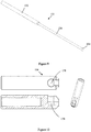
- the driver 31 comprises a cable 32 at a proximal end and a connector 34 at a distal end.
- the driver 30 further comprises a wire 136 between the cable 132 and the connector 134.
- the diameter of wire 136 is smaller than that of the cable 132 to allow the connector 134 to lock into the release portion 14.
- the connector 34 is configured to interface with release portion 14 in a manner to have rotational control over the clip 10 so that it may be disposed as desired.
- the release portion 14 of the clip 10 is removable and coupled with the connector 34 of the driver 30.
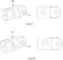
- the release portion 14 comprises a receiving chamber 70 with at least one side opening from the proximal end of the clip 10.
- the connector 34 is a T-like shape cylinder shown in Figures 8a and 8b .
- the receiving chamber 70 is a T-like shape chamber and is capable to receive the T-like shape connector 34.
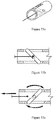
- the connector 134 is a ball shown in Figure 9 .
- the receiving chamber 170 is a ball-like shape chamber shown in Figure 10 and is capable to receive the ball connector 134.
- the connector 234 is a cube shown in Figure 11 .
- the receiving chamber 270 is a cube-like shape chamber shown in Figure 12 and is capable to receive the cube connector 234.
- the connector 334 and the release portion 314 can be interlock connectors such as, but not limited to, hand shake connectors.
- the release portion 314 comprises a stabilizing arm 372 and a tab 374.
- the connector 334 comprises a pocket 336.
- the pocket 336 can rest on the stabilizing arm and interlock with the tab 374. The lock can be released when needed.
- a person skilled in the art should reasonably understand that the configurations of the connectors 334 and the release portion 314 are interchangeable.
- locking mechanism may be other known designs or configurations besides the above described embodiments.
- the driving assembly further comprises a coupler.
- the coupler is disposed at the distal end of the outer sheath.
- the coupler is configured to removably couple to the collar.
- the coupler is configured to retain the collar during multiple open/close cycles while maintaining rotatability of the clip assembly.
- a proximal end of the collar comprises a groove.
- a distal end of the coupler comprises an edge configured to be engageable to the groove.
- the edge comprises a plurality of petals that can spread apart.
- the driving assembly may be other known designs or configurations besides the above described embodiments.
- the following steps may apply: 1) expose the clip at its open position; 2) adjust the driver to align the engagement portions to a treatment area; 3) the clip retracts into the outer sheath or collar to close the clip, which allows for a pre-load on the arms and increases its ability to grip the tissue; 4) push the pusher tube to move the collar passed the retention mechanism so that the clip at its fully closed position; 5) pull the outer sheath and the pusher tube back; 6) release the driver from the clip.
- the following steps may apply: 1) expose the clip at its open position; 2) adjust the driver to align the engagement portions to a treatment area; 3) the clip retracts into the collar to close the clip, which allows for a pre-load on the arms and increases its ability to grip the tissue; 4) push the pusher tube to advance the collar out of the coupler and past the retention fins on the clip to lock the clip closed and allow for release of the clip from the driver.
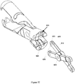
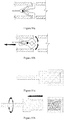
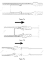
- the present subject matter further describes an introducer shown in Figures 17a-17b .
- the introducer comprises an internal chamber with an opening at a proximal end of the introducer and an opening at a distal end of the introducer.
- the distal end of the introducer is configured to allow the clip assembly and the distal end of the driving assembly to pass through.
- the proximal end of the introducer is configured to prevent the clip assembly from passing through.
- the proximal end of the introducer is configured to prevent the driving assembly from passing through.
- the introducer is configured to protect the clip during shipping and introduction through a biopsy valve on an endoscope.
- the distal end of the introducer is configured to couple into the biopsy valve.
- the minimum length L of the distal end of the introducer is about 5mm.
- the clip assembly is configured to enter the endoscope working channel through the biopsy valve.
- the internal chamber comprises an internal surface 400 adjacent to the proximal end.
- the internal chamber is a pod shape.
- the clip is configured to maintain a full open state within the internal chamber.
- the internal surface 400 is configured to force the clip to collapse as the catheter assembly is advanced from the proximal end towards the distal end. Once the clip is fully exposed from the distal end of the introducer and out of the working channel, the clip is configured to return to its fully open state. Once the clip assembly has been detached from the drive assembly, the driving assembly can be withdrawn from the endoscope.
- the clip 10 may have atraumatic geometry to prevent damage to the scope while advancing trough the biopsy channel.
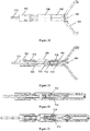
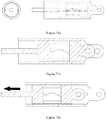
- the clip assembly comprises a base 500, a pair of jaws 502, and a switch 504.
- the driving assembly comprises an outer sheath 506, a coupler 508, and a driver 510.
- Figures 18 and 19 show the clip assembly and its driving assembly in the open position.
- Figures 20 shows the clip assembly and its driving assembly in the closed position.
- Figure 21 shows the clip assembly and its driving assembly in the stressed/locked position.
- Figure 22 shows the clip assembly and its driving assembly in the release/detach position.
- the clip assembly can freely move by the driving assembly from the open to closed position, and vice versa. Once the clip assembly enters the stressed/locked position, it cannot be opened again.
- the closed position allows for a pre-load on the arms and increases its ability to grip the tissue.
- the jaws keep stressed in order to achieve a better hemostatic or other desired effect.
- the base 500 is configured to hold and position the jaws 502 and the switch 504.
- the base 500 is configured to prevent the switch 504 from escaping from the distal end of the base 500.
- the base 500 comprises two halves.
- the jaws 502 are configured to collect and retain tissue.
- the jaws 502 are further configured to operably connect to a distal end of the base 500.
- a distal portion of the switch 504 is configured to actuate the jaws 502 between an open position and a closed position.
- a proximal portion of the switch 504 comprises a release portion 512.
- the release portion 512 is configured to removably couple with a distal end of the driver 510.
- An exemplary embodiment of connection between the release portion and the driver is a T-bar connection discussed in the previous embodiments.
- the release portion 512 and the distal portion of the switch 504 are separate two pieces and are connected by a pin 514.
- the distal portion of the switch 504 comprises a figure-8 shaped hole.
- the figure-8 shaped hole comprises a distal portion and a proximal portion.
- the figure-8 shaped hole is deposed at the release portion 512, instead of the distal portion of the switch 504.
- the mechanism may not be a figure-8 shaped hole and may be a geometry which achieves similar functionality.
- the switch 504 further comprises a tab 516.
- the tab 516 is configured to be movable within the base while the jaws move between the open and closed positions.
- the tab is further configured to be pulled outside the base and to prevent the switch 504 to move back into the base so as to lock the jaws as stressed.
- the release portion 512 and the distal portion of the switch 504 could be made in one piece so that the pin and the figure-8 shaped hole can be eliminated.
- the connection portion between the release portion 512 and the distal portion of the switch 504 is made of elastic materials so that it achieves the similar effects of the figure-8 shaped hole, which allows the clip assembly has the opened, closed, stressed/locked, and released positions.
- the coupler 508 is configured to couple with the outer sheath 506 by a barb.
- the coupler 508 and the outer sheath 506 can be one piece.
- the coupler 508 is configured to removably couple to the base 500.
- the coupler 508 is configured to retain the base 500 during multiple open/close cycles while maintaining rotatability of the clip assembly.
- a proximal end of the base 500 comprises a groove.
- a distal end of the coupler 508 comprises an edge configured to be engageable to the groove.
- the edge comprises a plurality of petals that can spread apart.
- the coupler 508 further comprises a bottleneck 520.
- the driver 510 comprises a wedge 522.
- the wedge 522 is configured to push the bottleneck 520 when the driver 510 pulls back and tries to detach the clip assembly from the driving assembly.
- the wedge 510 forces the petals of the coupler 508 apart. Then the edge and the groove are disengaged. The clip assembly therefore is detached.
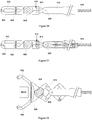
- the clip assembly comprises a first jaw 602, a second jaw 604, a first pivot 606, and an elastomeric band 608.
- the first jaw 602 is pivotally connected to the second jaw 604 at the first pivot 606.
- the first jaw comprises a distal arm and a proximal arm.
- the second jaw comprises a distal arm and a proximal arm.
- the elastomeric band 608 connects the distal arms of the first and second jaws and allows for normally closed first and second jaws. In some embodiments, the elastomeric band connects between the proximal arms of the first and second jaws. In some other embodiments, one elastomeric band connects between the distal arms of the first and second jaws; another elastomeric band connects between the proximal arms of the first and second jaws.
- the elastomeric band may be a ring around the first and second jaws, a band between the first and second jaws, or any other connection structures between the first and second jaws. In some embodiments, the elastomeric band is eliminated and the pivot comprises a common elastomeric structure so that the first and second jaws are normally closed.
- Each proximal end of the first and second jaws comprises a receiver 610.
- the receiver 610 is configured to removably receive the driving assembly so that the driving assembly may drive the clip assembly to be opened or closed.
- the driving assembly comprises an outer sheath 612, a fork 614, and a driver 616.
- the fork 614 is disposed within the outer sheath 612.
- the distal ends of the fork 614 are extended from the distal end of the outer sheath 612.
- the proximal end of the fork 614 is connected to the driver 616.
- the fork 614 is pivotally connected to the outer sheath 612 at a second pivot 628.
- Each of two distal ends of the fork 614 comprises an engagement portion 618.
- the engagement portion 618 is configured to engage with the receiver 610 of the clip assembly.
- the present subject matter further discloses an alternative embodiment of the clip assembly and its driving assembly.
- a single lever arm in the fork assembly 614 is used to open the clip assembly.
- the first pivot 606 is connected to the outer sheath 612 until deployment. After deployment, the first pivot 606 remains with the clip assembly.
- the clip assembly may detach from the fork at a different pivot 615 allowing the linkage arms to remain loosely attached to the clip assembly.
- the fork (assembly) can be any known structures of which the distal ends are opened when the drive mechanism is advanced in the distal direction.
- detachment of the clip assembly from the fork assembly 614 and/or the receiver 610 can be achieved by various methods such as mechanical detachment or by applying electrical current to sever the joints and that detachment may be achieved at any linkage point in the fork assembly 614.
- the driver 616 is metal and the fork assemble 614 is plastic. The driver 616 may be electrically heated and is able to melt at least a part of the fork assembly 614 to detach the fork assembly 614.
- the outer sheath 612 is mechanically breakable.
- the pivot 615 is mechanically breakable.
- the driver 616 is mechanically breakable at a point near the outer sheath 612.
- the fork 612 comprises asymmetrical arms. In some embodiments, the fork 612 comprises the distal arms with different length. In some embodiments, the fork 612 comprises the proximal arms with different length.
- the engagement portion 618 of the fork 614 comprises a detent 620.
- the detent 620 may be hemispherical or any other suitable shape.
- the receiver 610 comprises a pocket 624 for the detent 620 to engage with.
- the engagement portion 618 comprises a slot 622 to help the detent 620 to be compressed and to detach from the receiver 610.
- the engagement portion 618 comprises a bump 626 to aide in detaching the receiver 610. When the clip assembly clips on a tissue, the tissue prevents the clip assembly from being fully closed. When the fork is further closed, the bump presses against the edges of the pocket 624 and aides to the disengagement.
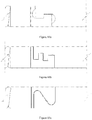
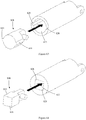
- the clip assembly comprises a clip 710 and a locking mechanism 720, driving assembly (catheter assembly) 730, release portion 714, pair of jaws 702.
- Figure 35a shows the clip assembly and its driving assembly in the open position.
- Figure 35b shows the clip assembly and its driving assembly in the closed/ stressed/ locked position.
- Figure 35c shows the clip assembly and its driving assembly in the release/detach position. The clip assembly can freely move by the driving assembly from the open to closed position, and vice versa. Once the clip assembly enters the stressed/locked position, it cannot be opened again.
- the release portion 714 of the clip 710 is removably coupled with the connector 734 of the driver 731.
- the release portion 714 comprises a receiving chamber 770 with at least one side opening from the proximal end of the clip 710.
- the connector 734 is a T-like shape cylinder and receiving chamber 770 is a T-like shape chamber and is capable to receive a T-like shape connector.
- the connector 734 is a ball and the receiving chamber 770 is a ball-like shape chamber and is capable to receive the ball connector 734.
- the connector 734 is a cube shown and the receiving chamber 770 is a cube-like shape chamber and is capable to receive the cube connector 734.
- the jaws 702 are connected by a pivot 728.
- the pivot may comprise of one or more pivot points and may be a separate piece or comprised of feature within the jaws 702.
- the pivot 728 may be comprised of any suitable material allowing for the closure of the jaws 702.
- the Jaws 702 may be comprised of one or more pieces linked via the pivot 728.
- the pivot 728 may contain additional components necessary for the operation of the assembly.
- the elastomeric band 708 connects the proximal arms of the jaws 702 and allows for normally opened positioned jaws.
- the elastomeric band may be a ring around the first and second jaws, a band between the first and second jaws, or any other connection structures between the first and second jaws.
- the elastomeric band is eliminated and the pivot comprises a common elastomeric structure so that the first and second jaws are normally opened.
- the elastomeric band is eliminated and the jaws are mechanically connected to the locking mechanism allowing for controlled opening and closing of the jaws.
- the driving assembly 730 causes the locking mechanism 720 to spread the proximal end of the clip assembly 710 thereby bringing the grab portion 712 of the jaws 702 together creating of a tissue entrapment area 721.
- This disengagement may be comprised of a break-away feature such that the connector 734 releases from receiving chamber 770 after the clip assembly 710 is in its stressed/ locked state.
- the locking mechanism 720 comprises of a retention pocket 729 on the outer portion. The retention pocket 729 interlocks with the retention fins 757 of the retention mechanism 716 thus locking the clip 710 in a closed position.
- the locking mechanism may be other known designs or configurations besides the above described embodiments which accomplish the task of spreading the proximal arms of the jaws 702.
- the driving assembly 730 disengages from the locking mechanism 720.
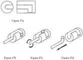
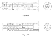
- the clip assembly 800 comprises a first jaw 802, a second jaw 804, a pivot 806, a release portion 808, and a housing 820.
- the first jaw 802 and the second jaw 804 are pivotally connected to the pivot 806.
- the pivot 806 may be removably attached to or a part of the first jaw 802, the second jaw 804, a release portion 808, or any combination thereof.
- the housing 820 comprises an internal channel 822. At least a portion of both the first jaw 802 and the second jaw 804 is disposed within the internal channel 822.
- the first jaw 802 and the second jaw 804 are configured to move along with the internal channel 822 between a fully closed position and a fully opened position.
- the driving assembly 900 or a driver of the driving assembly 900 is pushed towards its distal direction, the first jaw 802 and the second jaw 804 open.
- the driving assembly 900 or the driver of the driving assembly 900 is pulled towards its proximal direction, the first jaw 802 and the second jaw 804 close.
- both the first and second jaws are described as moving jaws above, a person skilled in the art should readily understand that the first jaw may be a stationary jaw.
- the clip assembly 800 may comprise more than two jaws.
- the housing 820 comprises a distal stopper 824.
- the distal stopper 824 is disposed at or near the distal end 836 of the internal channel 822.
- the distal stopper 824 is a pin removably passing through the housing 820.
- the distal stopper 824 is configured to force the first jaw 802 and the second jaw 804 fully open when the release portion moves to its most distal position.
- the distal stopper 824 is also configured to prevent the first jaw 802 and the second jaw 804 from completely falling out of the housing 820.
- the distal stopper 824 is also configured to prevent the first jaw 802 and the second jaw 804 from crossing the center plane bisecting the two arms.
- the housing 820 comprises a proximal stopper 826.
- the proximal stopper 826 is disposed at or near the proximal end 834 of the internal channel 820.
- the proximal stopper 826 is a ring attached to the internal channel 822.
- the proximal stopper 826 may prevent the release portion 808 from falling out of the housing 820.
- the proximal stopper 826 may provide a leverage surface other than the jaws to pull against when trying to dislodge the T-tag. Stresses can be balanced between that proximal stopper or the step in the jaws depending on the position of this step. In some embodiments, all force could be on the proximal stopper. In some embodiments, all force could be on the jaws. In some embodiments, all force could be shared between the proximal stopper and the jaws.
- the release portion 808 is proximal to the first jaw 802 and the second jaw 804. In some embodiments, the release portion 808 is pivotally connected to the pivot 806. In some embodiments, the release portion 808 is fixed to the pivot 806. In some embodiments, the release portion 808 is fixed to either arm or both arms. In some embodiments, the first jaw 802 and the second jaw 804 are disposed at each side of at least a portion of the release portion 808. The release portion 808 is configured to removably receive the driving assembly 900 so that the driving assembly 900 or the driver of the driving assembly 900 may drive the clip assembly 800 to be opened or closed.
- the first jaw 802 and the second jaw 804 achieve hemostatic effort.
- the first jaw 802 and the second jaw 804 bite on the target tissue.
- the friction between at least one of the first and second jaws 802, 804 and the internal channel 822 cause the first and second jaws 802, 804 to remain closed and achieve the hemostatic effort on the bitten tissue.
- the housing 820 comprises at least one alignment slot 828.
- the housing 820 comprises two alignment slots.
- the alignment slot 828 is configured to receive at least a portion of the first jaw 802 when the first jaw 802 in a non-closed position.
- the alignment slot 828 is configured to receive an alignment rib 830 of the first jaw 802. The alignment slot 828 prevents the first jaw 802 from unintended misalignment or rotation.
- the housing 820 comprises two alignment slots 828 for both the first jaw 802 and the second jaw 804.
- the alignment slot 828 is disposed at the internal channel 822.
- the alignment slot 828 is configured to receive at least a portion of the releasing portion 808.
- the alignment slot 828 prevents the releasing portion 808 from rotating within the internal channel 822, and therefore prevents the first and second jaws from unintended misalignment or rotation.
- the internal channel 822 with the alignment slots 828 receives the release portion 808 with alignment ribs 830.
- the internal channel 822 and the alignment slots 828 together form a non-cylindrical geometry, which receives a corresponding non-cylindrical geometry of the release portion 808.
- the alignment slots 828 are disposed on the housing 820 and receive pins 832 on the release portion 808. In some embodiments, the alignment slots 828 are disposed on the housing 820 and receive the pivot 806. A person skilled in the art should understand that the slot does not need to be visible from the outside of the housing; the slot does not to be on both sides; the pins do not need to be on the both sides; and the ribs do not need to be on the both sides.
- the shape of the housing 820 can be cylinder, cuboid, diamond, or other suitable geometries, as long as the releasing portion 808 has a corresponding geometry.
- the driving assembly 900 comprises an outer sheath 902, an inner tube 904, and a driver 906.
- the inner tube 904 is movably disposed within the outer sheath 902.
- the driver 906 is movably disposed within the inner tube 904.
- the driver 906 removably connects to the release portion 808 to form a driving engagement.
- the driver 906 is configured to move between its distal direction and its proximal direction to control the clip assembly 800 between open and closed.
- the driver 906 upon a predetermined pull force, the driver 906 separates from the release portion 808.
- Such predetermined pull force is larger than the force causing the clip assembly 800 closed and achieving a hemostatic effect.
- the distal end 908 of the outer sheath 902 and the inner tube 904 form a housing engagement with the proximal end 834 of the housing 820.
- the distal end 908 is configured to fully rotate 360 degrees without separating from the other part of the outer sheath 902.
- an interlocking rib and channel design comprised of two opposing ledges keep the distal end from disengaging yet allowing for circular rotation.
- each half of the engagement portion must have a feature, or set of features, with at least two opposing rotational engagement surfaces, that are located on either side of a center plane (that is coincidental with the long axis of the clip assembly) to have controllable rotation in two directions.
- An engaged rotational engagement is configured to rotate and disengage.
- the driving engagement and/or the housing engagement must provide interfacing surfaces. These interfacing surfaces are not parallel to the long axis of the assemblies. This may be a combination of flat surfaces and/or curved surfaces. This will be known as the total push/pull engagement surface. In some engagements, each half of the engagement portion must have a feature, or set of features, with at least two opposing total push/pull engagement surfaces. An engaged engagement is configured to move translationally and disengage.
- the structures of the driving engagement and the housing engagement are often interchangeable with/without some adaptive modifications. The engagement described in this application should be understood by the person skilled as used for the driving engagement and/or the housing engagement.
- the distal end 910 of the driver 906 comprises a tag 910.
- the tag 910 is a T-tag.
- the hook 910 could also be a Y, one sided L or J bend, an eyelet, or other suitable shapes.
- the tag 910 is received in the releasing portion 808 to form the driving engagement.
- the tag 910 promotes a stabilized push and pull motions under normal use. Once disengagement is required, the two t-shaped wires move radially inward, which allows the wires to slip out from the release portion 808, thus full disengagement is achieved.
- the tag 910 also helps for the rotation control.
- the engagement between the distal end 908 and the proximal end 834 is a handshake engagement.
- the distal end 908 and the proximal end 834 each have a handshake half.
- the inner tube 904 extends into the proximal end 834 of the housing 820 and prevents the distal end 908 and the proximal end 834 from disengaging. Once the inner tube 904 is retracted out of the proximal end 834, the engaged distal end 908 and the proximal end 834 are able to be separated.
- the inner tube 904 that is retracted to allow disengagement must have a diameter such that the distal end 908 and the proximal end 834 remain together until purposefully removed.
- the combined clearance of both inner diameters ID of the handshake halves with the outer diameter OD of the inner tube 904 must be less than the height H of the total engagement surface when measured perpendicular to the long axis of the clip assembly 800.
- some embodiments of the clip assembly described above are made of electrically nonconductive or non-magnetic material.
- the clip assembly has all components that are left in the patient.
- At least one or multiple portions of the device may be constructed of or coated in a radio-opaque or radio-visible material to be identifiable with medical imaging technologies.
Claims (14)
- Endoskopievorrichtung mit
einer Klammeranordnung (10), dieüber eine erste Backe (50),über eine zweite Backe (60),über ein Gehäuse (20) verfügt, das einen inneren Kanal aufweist, wobei wenigstens ein Bereich der ersten und der zweiten Backen innerhalb des inneren Kanals angeordnet ist, wobei sich die ersten und zweiten Backen wahlfrei innerhalb des inneren Kanals zwischen einer vollständig geschlossenen Stellung und einer vollständig geöffneten Stellung bewegen, undmit einem Freigabeabschnitt (14), der die ersten und zweiten Backen verbindet, wobei wenigstens ein Bereich des Freigabeabschnitts proximal von den ersten und zweiten Backen angeordnet ist, undmit einer Antriebsanordnung (30), dieeine äußere Hülse (42) undeine innere Röhre (40) aufweist,die innerhalb der äußeren Hülse angeordnet ist, und die dadurch gekennzeichnet ist, dass sie mit einem Antriebsmittel (31) ausgestattet ist, das beweglich innerhalb der inneren Röhre angeordnet und entfernbar innerhalb des Freigabeabschnitts aufgenommen ist, wobei das Antriebsmittel von dem Freigabeabschnitt durch eine vorbestimmte Zugkraft zerstörungsfrei freigebbar ist,wobei das Gehäuse und die äußere Hülse eine lösbare Eingriffsanordnung bilden und wobei die sich innerhalb des Gehäuses erstreckende innere Röhre die Eingriffsanordnung davon abhält, außer Eingriff zu kommen. - Endoskopievorrichtung nach Anspruch 1, wobei die Klammeranordnung weiterhin über einen distalen Anschlag verfügt, der an einem distalen Ende des inneren Kanals angeordnet und dazu eingerichtet ist, die ersten und zweiten Backen zur vollständigen Öffnung zu bringen, wenn sich der Freigabeabschnitt in seine äußerste distale Stellung bewegt.
- Endoskopievorrichtung nach Anspruch 1, bei der das Antriebsmittel ein T-Stück aufweist, das von dem Freigabeabschnitt aufgenommen ist, wobei sich zwei Drähte des T-Stücks wahlfrei in radialer Richtung innerhalb und aus dem Freigabeabschnitt austretend bewegen, wenn eine vorbestimmte Kraft beaufschlagt ist.
- Endoskopievorrichtung nach Anspruch 1, wobei die Klammeranordnung aus einem elektrisch nichtleitenden oder nichtmagnetischen Material für diejenigen Komponenten hergestellt ist, die in einem Patienten verbleiben.
- Endoskopievorrichtung nach Anspruch 1, wobei die Klammeranordnung über ein Gelenk verfügt, wobei die ersten und zweiten Klammern das Gelenk gelenkig verbinden.
- Endoskopievorrichtung nach Anspruch 5, bei der der Freigabeabschnitt gelenkig mit dem Gelenk verbunden ist.
- Endoskopievorrichtung nach Anspruch 5, bei der der Freigabeabschnitt fest an dem Gelenk angebracht ist.
- Endoskopievorrichtung nach Anspruch 1, bei der die ersten und zweiten Backen beidseitig wenigstens eines Bereichs des Freigabeabschnitts angeordnet sind.
- Endoskopievorrichtung nach Anspruch 1, bei der das Gehäuse einen Ausrichtschlitz aufweist, der dazu eingerichtet ist, wenigstens einen Bereich der ersten Backe aufzunehmen, wenn die erste Backe in einer nicht geschlossenen Stellung ist.
- Endoskopievorrichtung nach Anspruch 9, bei der der Ausrichtschlitz dazu eingerichtet ist, eine Ausrichtrippe der ersten Backe aufzunehmen.
- Endoskopievorrichtung nach Anspruch 1, bei der das Gehäuse zwei Ausrichtschlitze aufweist.
- Endoskopievorrichtung nach Anspruch 1, bei der der Unterschied zwischen einem Innendurchmesser eines proximalen Endes des inneren Kanals oder einem distalen Ende der äußeren Hülse und einem äußeren Durchmesser der inneren Röhre kleiner als eine Höhe einer gesamten Eingriffsoberfläche bei Messung rechtwinklig zu einer Längsachse der chirurgischen Endoskopievorrichtung ist.
- Endoskopievorrichtung nach Anspruch 1, bei der ein distales Ende der äußeren Hülse dazu eingerichtet ist, vollständig um 360 Grad drehbar zu sein, ohne sich von dem anderen Teil der äußeren Hülse zu lösen.
- Endoskopievorrichtung nach Anspruch 1, bei der eine Geometrie des inneren Kanals einer Geometrie des Freigabeabschnitts entspricht.
Applications Claiming Priority (3)
| Application Number | Priority Date | Filing Date | Title |
|---|---|---|---|
| US201762586617P | 2017-11-15 | 2017-11-15 | |
| US201862767353P | 2018-11-14 | 2018-11-14 | |
| PCT/US2018/061321 WO2019099698A1 (en) | 2017-11-15 | 2018-11-15 | Clip and clip assembly |
Publications (2)
| Publication Number | Publication Date |
|---|---|
| EP3709898A1 EP3709898A1 (de) | 2020-09-23 |
| EP3709898B1 true EP3709898B1 (de) | 2021-09-22 |
Family
ID=64572604
Family Applications (1)
| Application Number | Title | Priority Date | Filing Date |
|---|---|---|---|
| EP18812575.1A Active EP3709898B1 (de) | 2017-11-15 | 2018-11-15 | Clip und clip-anordnung |
Country Status (4)
| Country | Link |
|---|---|
| US (2) | US11751882B2 (de) |
| EP (1) | EP3709898B1 (de) |
| JP (1) | JP7330964B2 (de) |
| WO (1) | WO2019099698A1 (de) |
Families Citing this family (7)
| Publication number | Priority date | Publication date | Assignee | Title |
|---|---|---|---|---|
| US11413030B2 (en) * | 2018-11-08 | 2022-08-16 | William MONTROSS | Montross button |
| WO2020136906A1 (ja) * | 2018-12-28 | 2020-07-02 | オリンパス株式会社 | 結紮装置および係合方法 |
| US11622765B2 (en) * | 2019-01-03 | 2023-04-11 | Olympus Corporation | Clipping device for large defects, perforations and fistulas |
| CN110464410A (zh) * | 2019-07-03 | 2019-11-19 | 安瑞医疗器械(杭州)有限公司 | 配合内窥镜使用的夹子装置及其夹持部 |
| JPWO2021156930A1 (de) * | 2020-02-04 | 2021-08-12 | ||
| WO2022056223A1 (en) * | 2020-09-11 | 2022-03-17 | The Board Of Trustees Of The Leland Stanford Junior University | Devices and methods directed to sensing using synthetic materials |
| JP2022066160A (ja) * | 2020-10-16 | 2022-04-28 | オリンパスメディカルシステムズ株式会社 | 湾曲可能なクリップデバイス |
Family Cites Families (18)
| Publication number | Priority date | Publication date | Assignee | Title |
|---|---|---|---|---|
| JP4472217B2 (ja) | 2000-10-16 | 2010-06-02 | オリンパス株式会社 | 生体組織のクリップ装置 |
| JP4097924B2 (ja) * | 2001-02-05 | 2008-06-11 | オリンパス株式会社 | 生体組織のクリップ装置 |
| JP4059656B2 (ja) * | 2001-03-07 | 2008-03-12 | オリンパス株式会社 | 生体組織のクリップ装置 |
| JP4827304B2 (ja) * | 2001-03-14 | 2011-11-30 | オリンパス株式会社 | 生体組織のクリップ装置 |
| US7727247B2 (en) * | 2002-08-21 | 2010-06-01 | Olympus Corporation | Living tissue ligation device |
| DE10334083A1 (de) * | 2003-07-26 | 2005-02-24 | Carl Stahl Gmbh | Verfahren und Vorrichtung zur endoskopischen Applizierung von sich schließenden medizinischen Clips |
| JP4758173B2 (ja) | 2004-12-24 | 2011-08-24 | オリンパス株式会社 | 結紮装置 |
| US8080021B2 (en) * | 2005-01-11 | 2011-12-20 | Boston Scientific Scimed, Inc. | Multiple clip deployment magazine |
| AU2007225266B2 (en) | 2006-03-10 | 2013-06-06 | Cook Medical Technologies Llc | A clip device and a protective cap for drawing the target tissue into it before the clip is deployed |
| US8152822B2 (en) * | 2006-12-05 | 2012-04-10 | Cook Medical Technologies Llc | Combination therapy hemostatic clip |
| US8162959B2 (en) * | 2007-05-03 | 2012-04-24 | Boston Scientific Scimed, Inc. | Single stage hemostasis clipping device |
| US9232947B2 (en) * | 2009-02-17 | 2016-01-12 | The Board Of Trustees Of The Leland Stanford Junior University | Closure device and method |
| JP5588711B2 (ja) | 2010-03-30 | 2014-09-10 | 富士フイルム株式会社 | 結紮装置 |
| CN103124530B (zh) * | 2010-09-22 | 2016-03-30 | 富士胶片株式会社 | 结扎装置和在该结扎装置中使用的夹子单元 |
| JP5343113B2 (ja) * | 2011-09-15 | 2013-11-13 | 富士フイルム株式会社 | クリップユニット及びこれを用いる結紮装置 |
| EP2819595A1 (de) | 2012-02-28 | 2015-01-07 | Boston Scientific Scimed, Inc. | Klammerapplikator |
| CN107371362B (zh) * | 2015-05-19 | 2020-05-05 | 奥林巴斯株式会社 | 夹子装置 |
| WO2016190190A1 (ja) * | 2015-05-27 | 2016-12-01 | オリンパス株式会社 | 内視鏡用処置具 |
-
2018
- 2018-11-15 EP EP18812575.1A patent/EP3709898B1/de active Active
- 2018-11-15 US US16/192,202 patent/US11751882B2/en active Active
- 2018-11-15 WO PCT/US2018/061321 patent/WO2019099698A1/en unknown
- 2018-11-15 JP JP2020526592A patent/JP7330964B2/ja active Active
-
2023
- 2023-07-24 US US18/357,715 patent/US20230363764A1/en active Pending
Also Published As
| Publication number | Publication date |
|---|---|
| US20190150929A1 (en) | 2019-05-23 |
| US20230363764A1 (en) | 2023-11-16 |
| US11751882B2 (en) | 2023-09-12 |
| JP2021502861A (ja) | 2021-02-04 |
| WO2019099698A1 (en) | 2019-05-23 |
| JP7330964B2 (ja) | 2023-08-22 |
| EP3709898A1 (de) | 2020-09-23 |
Similar Documents
| Publication | Publication Date | Title |
|---|---|---|
| EP3709898B1 (de) | Clip und clip-anordnung | |
| ES2708987T3 (es) | Pinza de agarre | |
| AU2013226309B2 (en) | Omnidirectional closure clip | |
| US20070282355A1 (en) | Release mechanisms for a clip device | |
| JP7035200B2 (ja) | 止血クリップ | |
| AU2018345332B2 (en) | Devices and methods for tissue retraction | |
| ES2939069T3 (es) | Mecanismo de despliegue en dos etapas de pinza hemostática para eliminar partes desprendidas | |
| CN111526804B (zh) | 双支撑钳口设计 | |
| JP2023534025A (ja) | 内視鏡粘膜下切開に用いる磁気的に取り付け可能な生体組織クリップ | |
| US20200146686A1 (en) | Clip and clip assembly | |
| JP2023162219A (ja) | 止血クリップの短縮化システム | |
| KR20210127933A (ko) | 접을 수 있는 캡슐을 구비한 지혈 클립 | |
| JP2022525532A (ja) | 止血クリップの長さが短縮された配備メカニズム | |
| US20230263533A1 (en) | Clip, system, and clip deployment method | |
| KR20240005090A (ko) | 콜릿 전개가능한 지혈 클립 | |
| CN117396143A (zh) | 可重新定位的内镜吻合夹 |
Legal Events
| Date | Code | Title | Description |
|---|---|---|---|
| STAA | Information on the status of an ep patent application or granted ep patent |
Free format text: STATUS: UNKNOWN |
|
| STAA | Information on the status of an ep patent application or granted ep patent |
Free format text: STATUS: THE INTERNATIONAL PUBLICATION HAS BEEN MADE |
|
| PUAI | Public reference made under article 153(3) epc to a published international application that has entered the european phase |
Free format text: ORIGINAL CODE: 0009012 |
|
| STAA | Information on the status of an ep patent application or granted ep patent |
Free format text: STATUS: REQUEST FOR EXAMINATION WAS MADE |
|
| 17P | Request for examination filed |
Effective date: 20200508 |
|
| AK | Designated contracting states |
Kind code of ref document: A1 Designated state(s): AL AT BE BG CH CY CZ DE DK EE ES FI FR GB GR HR HU IE IS IT LI LT LU LV MC MK MT NL NO PL PT RO RS SE SI SK SM TR |
|
| AX | Request for extension of the european patent |
Extension state: BA ME |
|
| DAV | Request for validation of the european patent (deleted) | ||
| DAX | Request for extension of the european patent (deleted) | ||
| GRAP | Despatch of communication of intention to grant a patent |
Free format text: ORIGINAL CODE: EPIDOSNIGR1 |
|
| STAA | Information on the status of an ep patent application or granted ep patent |
Free format text: STATUS: GRANT OF PATENT IS INTENDED |
|
| INTG | Intention to grant announced |
Effective date: 20210421 |
|
| GRAS | Grant fee paid |
Free format text: ORIGINAL CODE: EPIDOSNIGR3 |
|
| GRAA | (expected) grant |
Free format text: ORIGINAL CODE: 0009210 |
|
| STAA | Information on the status of an ep patent application or granted ep patent |
Free format text: STATUS: THE PATENT HAS BEEN GRANTED |
|
| AK | Designated contracting states |
Kind code of ref document: B1 Designated state(s): AL AT BE BG CH CY CZ DE DK EE ES FI FR GB GR HR HU IE IS IT LI LT LU LV MC MK MT NL NO PL PT RO RS SE SI SK SM TR |
|
| REG | Reference to a national code |
Ref country code: GB Ref legal event code: FG4D |
|
| REG | Reference to a national code |
Ref country code: IE Ref legal event code: FG4D |
|
| REG | Reference to a national code |
Ref country code: DE Ref legal event code: R096 Ref document number: 602018024049 Country of ref document: DE |
|
| REG | Reference to a national code |
Ref country code: CH Ref legal event code: EP Ref country code: AT Ref legal event code: REF Ref document number: 1431685 Country of ref document: AT Kind code of ref document: T Effective date: 20211015 |
|
| REG | Reference to a national code |
Ref country code: LT Ref legal event code: MG9D |
|
| REG | Reference to a national code |
Ref country code: NL Ref legal event code: MP Effective date: 20210922 |
|
| PG25 | Lapsed in a contracting state [announced via postgrant information from national office to epo] |
Ref country code: RS Free format text: LAPSE BECAUSE OF FAILURE TO SUBMIT A TRANSLATION OF THE DESCRIPTION OR TO PAY THE FEE WITHIN THE PRESCRIBED TIME-LIMIT Effective date: 20210922 Ref country code: SE Free format text: LAPSE BECAUSE OF FAILURE TO SUBMIT A TRANSLATION OF THE DESCRIPTION OR TO PAY THE FEE WITHIN THE PRESCRIBED TIME-LIMIT Effective date: 20210922 Ref country code: FI Free format text: LAPSE BECAUSE OF FAILURE TO SUBMIT A TRANSLATION OF THE DESCRIPTION OR TO PAY THE FEE WITHIN THE PRESCRIBED TIME-LIMIT Effective date: 20210922 Ref country code: BG Free format text: LAPSE BECAUSE OF FAILURE TO SUBMIT A TRANSLATION OF THE DESCRIPTION OR TO PAY THE FEE WITHIN THE PRESCRIBED TIME-LIMIT Effective date: 20211222 Ref country code: LT Free format text: LAPSE BECAUSE OF FAILURE TO SUBMIT A TRANSLATION OF THE DESCRIPTION OR TO PAY THE FEE WITHIN THE PRESCRIBED TIME-LIMIT Effective date: 20210922 Ref country code: NO Free format text: LAPSE BECAUSE OF FAILURE TO SUBMIT A TRANSLATION OF THE DESCRIPTION OR TO PAY THE FEE WITHIN THE PRESCRIBED TIME-LIMIT Effective date: 20211222 Ref country code: HR Free format text: LAPSE BECAUSE OF FAILURE TO SUBMIT A TRANSLATION OF THE DESCRIPTION OR TO PAY THE FEE WITHIN THE PRESCRIBED TIME-LIMIT Effective date: 20210922 |
|
| REG | Reference to a national code |
Ref country code: AT Ref legal event code: MK05 Ref document number: 1431685 Country of ref document: AT Kind code of ref document: T Effective date: 20210922 |
|
| PG25 | Lapsed in a contracting state [announced via postgrant information from national office to epo] |
Ref country code: LV Free format text: LAPSE BECAUSE OF FAILURE TO SUBMIT A TRANSLATION OF THE DESCRIPTION OR TO PAY THE FEE WITHIN THE PRESCRIBED TIME-LIMIT Effective date: 20210922 Ref country code: GR Free format text: LAPSE BECAUSE OF FAILURE TO SUBMIT A TRANSLATION OF THE DESCRIPTION OR TO PAY THE FEE WITHIN THE PRESCRIBED TIME-LIMIT Effective date: 20211223 |
|
| PG25 | Lapsed in a contracting state [announced via postgrant information from national office to epo] |
Ref country code: AT Free format text: LAPSE BECAUSE OF FAILURE TO SUBMIT A TRANSLATION OF THE DESCRIPTION OR TO PAY THE FEE WITHIN THE PRESCRIBED TIME-LIMIT Effective date: 20210922 |
|
| PG25 | Lapsed in a contracting state [announced via postgrant information from national office to epo] |
Ref country code: IS Free format text: LAPSE BECAUSE OF FAILURE TO SUBMIT A TRANSLATION OF THE DESCRIPTION OR TO PAY THE FEE WITHIN THE PRESCRIBED TIME-LIMIT Effective date: 20220122 Ref country code: SK Free format text: LAPSE BECAUSE OF FAILURE TO SUBMIT A TRANSLATION OF THE DESCRIPTION OR TO PAY THE FEE WITHIN THE PRESCRIBED TIME-LIMIT Effective date: 20210922 Ref country code: RO Free format text: LAPSE BECAUSE OF FAILURE TO SUBMIT A TRANSLATION OF THE DESCRIPTION OR TO PAY THE FEE WITHIN THE PRESCRIBED TIME-LIMIT Effective date: 20210922 Ref country code: PT Free format text: LAPSE BECAUSE OF FAILURE TO SUBMIT A TRANSLATION OF THE DESCRIPTION OR TO PAY THE FEE WITHIN THE PRESCRIBED TIME-LIMIT Effective date: 20220124 Ref country code: PL Free format text: LAPSE BECAUSE OF FAILURE TO SUBMIT A TRANSLATION OF THE DESCRIPTION OR TO PAY THE FEE WITHIN THE PRESCRIBED TIME-LIMIT Effective date: 20210922 Ref country code: NL Free format text: LAPSE BECAUSE OF FAILURE TO SUBMIT A TRANSLATION OF THE DESCRIPTION OR TO PAY THE FEE WITHIN THE PRESCRIBED TIME-LIMIT Effective date: 20210922 Ref country code: ES Free format text: LAPSE BECAUSE OF FAILURE TO SUBMIT A TRANSLATION OF THE DESCRIPTION OR TO PAY THE FEE WITHIN THE PRESCRIBED TIME-LIMIT Effective date: 20210922 Ref country code: EE Free format text: LAPSE BECAUSE OF FAILURE TO SUBMIT A TRANSLATION OF THE DESCRIPTION OR TO PAY THE FEE WITHIN THE PRESCRIBED TIME-LIMIT Effective date: 20210922 Ref country code: CZ Free format text: LAPSE BECAUSE OF FAILURE TO SUBMIT A TRANSLATION OF THE DESCRIPTION OR TO PAY THE FEE WITHIN THE PRESCRIBED TIME-LIMIT Effective date: 20210922 Ref country code: AL Free format text: LAPSE BECAUSE OF FAILURE TO SUBMIT A TRANSLATION OF THE DESCRIPTION OR TO PAY THE FEE WITHIN THE PRESCRIBED TIME-LIMIT Effective date: 20210922 |
|
| REG | Reference to a national code |
Ref country code: DE Ref legal event code: R097 Ref document number: 602018024049 Country of ref document: DE |
|
| PG25 | Lapsed in a contracting state [announced via postgrant information from national office to epo] |
Ref country code: MC Free format text: LAPSE BECAUSE OF FAILURE TO SUBMIT A TRANSLATION OF THE DESCRIPTION OR TO PAY THE FEE WITHIN THE PRESCRIBED TIME-LIMIT Effective date: 20210922 |
|
| REG | Reference to a national code |
Ref country code: CH Ref legal event code: PL |
|
| PG25 | Lapsed in a contracting state [announced via postgrant information from national office to epo] |
Ref country code: LU Free format text: LAPSE BECAUSE OF NON-PAYMENT OF DUE FEES Effective date: 20211115 Ref country code: DK Free format text: LAPSE BECAUSE OF FAILURE TO SUBMIT A TRANSLATION OF THE DESCRIPTION OR TO PAY THE FEE WITHIN THE PRESCRIBED TIME-LIMIT Effective date: 20210922 Ref country code: BE Free format text: LAPSE BECAUSE OF NON-PAYMENT OF DUE FEES Effective date: 20211130 |
|
| PLBE | No opposition filed within time limit |
Free format text: ORIGINAL CODE: 0009261 |
|
| STAA | Information on the status of an ep patent application or granted ep patent |
Free format text: STATUS: NO OPPOSITION FILED WITHIN TIME LIMIT |
|
| REG | Reference to a national code |
Ref country code: BE Ref legal event code: MM Effective date: 20211130 |
|
| 26N | No opposition filed |
Effective date: 20220623 |
|
| PG25 | Lapsed in a contracting state [announced via postgrant information from national office to epo] |
Ref country code: IE Free format text: LAPSE BECAUSE OF NON-PAYMENT OF DUE FEES Effective date: 20211115 |
|
| PG25 | Lapsed in a contracting state [announced via postgrant information from national office to epo] |
Ref country code: SI Free format text: LAPSE BECAUSE OF FAILURE TO SUBMIT A TRANSLATION OF THE DESCRIPTION OR TO PAY THE FEE WITHIN THE PRESCRIBED TIME-LIMIT Effective date: 20210922 |
|
| P01 | Opt-out of the competence of the unified patent court (upc) registered |
Effective date: 20230513 |
|
| PG25 | Lapsed in a contracting state [announced via postgrant information from national office to epo] |
Ref country code: CY Free format text: LAPSE BECAUSE OF FAILURE TO SUBMIT A TRANSLATION OF THE DESCRIPTION OR TO PAY THE FEE WITHIN THE PRESCRIBED TIME-LIMIT Effective date: 20210922 |
|
| PG25 | Lapsed in a contracting state [announced via postgrant information from national office to epo] |
Ref country code: SM Free format text: LAPSE BECAUSE OF FAILURE TO SUBMIT A TRANSLATION OF THE DESCRIPTION OR TO PAY THE FEE WITHIN THE PRESCRIBED TIME-LIMIT Effective date: 20210922 Ref country code: LI Free format text: LAPSE BECAUSE OF NON-PAYMENT OF DUE FEES Effective date: 20220630 Ref country code: HU Free format text: LAPSE BECAUSE OF FAILURE TO SUBMIT A TRANSLATION OF THE DESCRIPTION OR TO PAY THE FEE WITHIN THE PRESCRIBED TIME-LIMIT; INVALID AB INITIO Effective date: 20181115 Ref country code: CH Free format text: LAPSE BECAUSE OF NON-PAYMENT OF DUE FEES Effective date: 20220630 |
|
| PGFP | Annual fee paid to national office [announced via postgrant information from national office to epo] |
Ref country code: GB Payment date: 20231127 Year of fee payment: 6 |
|
| PGFP | Annual fee paid to national office [announced via postgrant information from national office to epo] |
Ref country code: IT Payment date: 20231122 Year of fee payment: 6 Ref country code: FR Payment date: 20231127 Year of fee payment: 6 Ref country code: DE Payment date: 20231129 Year of fee payment: 6 |