EP3708395A1 - Luftausströmer für den innenraum eines kraftfahrzeuges - Google Patents
Luftausströmer für den innenraum eines kraftfahrzeuges Download PDFInfo
- Publication number
- EP3708395A1 EP3708395A1 EP20159833.1A EP20159833A EP3708395A1 EP 3708395 A1 EP3708395 A1 EP 3708395A1 EP 20159833 A EP20159833 A EP 20159833A EP 3708395 A1 EP3708395 A1 EP 3708395A1
- Authority
- EP
- European Patent Office
- Prior art keywords
- expanded metal
- air
- lamella
- housing
- metal cover
- Prior art date
- Legal status (The legal status is an assumption and is not a legal conclusion. Google has not performed a legal analysis and makes no representation as to the accuracy of the status listed.)
- Granted
Links
Images




Classifications
-
- B—PERFORMING OPERATIONS; TRANSPORTING
- B60—VEHICLES IN GENERAL
- B60H—ARRANGEMENTS OF HEATING, COOLING, VENTILATING OR OTHER AIR-TREATING DEVICES SPECIALLY ADAPTED FOR PASSENGER OR GOODS SPACES OF VEHICLES
- B60H1/00—Heating, cooling or ventilating devices
- B60H1/34—Nozzles; Air-diffusers
- B60H1/3407—Nozzles; Air-diffusers providing an air stream in a fixed direction, e.g. using a grid or porous panel
-
- B—PERFORMING OPERATIONS; TRANSPORTING
- B60—VEHICLES IN GENERAL
- B60H—ARRANGEMENTS OF HEATING, COOLING, VENTILATING OR OTHER AIR-TREATING DEVICES SPECIALLY ADAPTED FOR PASSENGER OR GOODS SPACES OF VEHICLES
- B60H1/00—Heating, cooling or ventilating devices
- B60H1/34—Nozzles; Air-diffusers
- B60H1/3414—Nozzles; Air-diffusers with means for adjusting the air stream direction
-
- B—PERFORMING OPERATIONS; TRANSPORTING
- B60—VEHICLES IN GENERAL
- B60H—ARRANGEMENTS OF HEATING, COOLING, VENTILATING OR OTHER AIR-TREATING DEVICES SPECIALLY ADAPTED FOR PASSENGER OR GOODS SPACES OF VEHICLES
- B60H1/00—Heating, cooling or ventilating devices
- B60H1/00642—Control systems or circuits; Control members or indication devices for heating, cooling or ventilating devices
- B60H1/00814—Control systems or circuits characterised by their output, for controlling particular components of the heating, cooling or ventilating installation
- B60H1/00821—Control systems or circuits characterised by their output, for controlling particular components of the heating, cooling or ventilating installation the components being ventilating, air admitting or air distributing devices
- B60H1/00871—Air directing means, e.g. blades in an air outlet
-
- B—PERFORMING OPERATIONS; TRANSPORTING
- B60—VEHICLES IN GENERAL
- B60H—ARRANGEMENTS OF HEATING, COOLING, VENTILATING OR OTHER AIR-TREATING DEVICES SPECIALLY ADAPTED FOR PASSENGER OR GOODS SPACES OF VEHICLES
- B60H1/00—Heating, cooling or ventilating devices
- B60H1/24—Ventilating devices where the heating or cooling is irrelevant
- B60H1/241—Ventilating devices where the heating or cooling is irrelevant characterised by the location of ventilation devices in the vehicle
- B60H1/242—Ventilating devices where the heating or cooling is irrelevant characterised by the location of ventilation devices in the vehicle located in the front area
-
- B—PERFORMING OPERATIONS; TRANSPORTING
- B60—VEHICLES IN GENERAL
- B60H—ARRANGEMENTS OF HEATING, COOLING, VENTILATING OR OTHER AIR-TREATING DEVICES SPECIALLY ADAPTED FOR PASSENGER OR GOODS SPACES OF VEHICLES
- B60H1/00—Heating, cooling or ventilating devices
- B60H1/34—Nozzles; Air-diffusers
- B60H1/3414—Nozzles; Air-diffusers with means for adjusting the air stream direction
- B60H1/3421—Nozzles; Air-diffusers with means for adjusting the air stream direction using only pivoting shutters
Definitions
- Such air vents are well known from the prior art, which cannot be documented in printed literature, and serve to supply air into the vehicle interior, for example to dry off condensate on a windshield.
- Such air vents designed as defrosters have air outflow openings and at least one fixed lamella which directs an air flow towards the windshield and are subject to strict legal standards with regard to their performance.
- the air vents are subject to the risk that foreign objects, previously placed on the dashboard, can unintentionally get into the air vents and thus the functionality of the air vents is considerably restricted. Removing these foreign bodies is associated with great effort.
- expanded metals and structures imitated by expanded metals are known. These serve, for example, to cover a large area of the dashboard or speaker openings and thus create a uniform surface that is particularly aesthetically pleasing. Covering air vents is avoided entirely because this converts the directed air flow into a diffuse air flow. In the area of defrosters, the prescribed statutory performance standard cannot be met. In the area of other air vents, the cover made of expanded metal or imitated structures is also dispensed with.
- the invention overcomes the prejudice of the prior art that expanded metals are not air-directing. It has surprisingly been found that the directed air flow retains its defined orientation despite flowing through the expanded metal. In extensive tests it has been shown that the directed air flow is maintained after passing through the expanded metal if the edge of the lamella close to the expanded metal is brought up to the expanded metal cover with the exception of a fit due to the assembly. The performance of a defroster is therefore not reduced by the arrangement of the plug-in metal cover on the air outlet opening of the air outlet and continues to meet the statutory requirements.
- the air vent according to EP 3 164 280 B1 can also be provided with such an expanded metal cover.
- the air flow remains directed after it has passed through the expanded metal cover, if care is taken that the edge of the lamella close to the expanded metal is brought so close to the expanded metal cover that only the clearance between the expanded metal and the edge of the lamella close to the expanded metal due to the assembly remains.
- the invention thus overcomes the immovable knowledge that an air flow flowing through the expanded metal cover cannot be directed.
- the invention now allows the risk of foreign bodies to be prevented from entering.
- the meshes of the expanded metal cover are arranged so closely to one another that at most tiny foreign bodies, which do not impair the functionality of the air vent, penetrate the openings.
- the expanded metal cover is particularly advantageous due to its structure. It is aesthetically pleasing and meets the high visual requirements of the vehicle industry on the vehicle interior. Since defrosters and other air vents can now also be covered with the expanded metal without any loss of functionality, the entire dashboard can be designed over a large area and uniformly, which optimizes the overall interior design of the motor vehicle.
- the at least one lamella is arranged in the housing so that it can pivot about an axis, so that the lamella angle relative to the longitudinal axis of the housing can be changed.
- the pivot axis of the slats is arranged close to expanded metal in such a way that the increasing distance between the edge of the slat and the expanded metal cover due to the pivoting movement of the slats still enables an air flow leaving the cover in a directed manner.
- the air flow is thus initially aligned by means of the pivotable lamellae in the interior of the housing and then diverted to the expanded metal cover without any turbulence between Lamella and expanded metal cover occur.
- the air flow is thus directed into the interior of the motor vehicle.
- the edge near the expanded metal ends in a lamella edge and that the pivot axis essentially coincides with the lamella edge. It is particularly advantageous in this embodiment that the distance between the edge of the lamella and the expanded metal cover is reduced to a minimum despite the pivoting movement of the lamella. The air flow leaving the expanded metal cover can thus be directed.
- the expanded metal cover has a convex or concave curvature, the plane of curvature of which is aligned parallel to the pivot axis of the lamella.
- the curvature of the expanded metal cover can be convex or concave, for example, and have a constant radius, the curvature then being formed in the shape of a cylinder.
- a curvature with an unsteady radius for example with an oval course, is also conceivable.
- Both the convex and the concave curvature of the expanded metal cover triggers an air deflection of the exiting air flow, whereby new types of flow patterns can be generated.
- the air flow which is deflected on a convexly curved expanded metal cover, is released into the passenger's interior in a fan-like manner.
- Such a fanning out requires a large area Air flow to the passengers or the windshield. This means that a larger area can be covered with air in a short time. The intensity of the air flow can decrease and is then particularly pleasant for the passenger.
- a concave curved expanded metal cover means that the exiting air flow is bundled and thus a precise, linear alignment of the air flow is possible.
- This linearly exiting air flow can, for example, be directed specifically at a point on the windshield covered with condensate in order to dry it off quickly.
- the concave, curved expanded metal cover ensures precise and effective ventilation of the passenger compartment.
- the air flow is directed by means of a combination of the curved expanded metal cover and the lamellae arranged behind the curved expanded metal cover. This combination enables the air flow to be individually adjusted for the passenger, with the pleasure flow being easily adapted to any situation.
- the web walls of the curved expanded metal cover each span a plane and that these each intersect the longitudinal axis of the housing, the respective intersection angle of the plane and the longitudinal axis of the housing increasing as the distance between the respective web walls and the longitudinal axis of the housing increases.
- the amount of change in the cutting angle is constant from cutting angle to cutting angle, as in the case of a cylindrical configuration of the expanded metal cover.
- the amount of change in the cutting angle increases from the cutting angle Cutting angle is different, as with a curved plug-in metal cover with an unsteady radius.
- one embodiment of the invention provides that the air vent is designed as a defroster for the windshield of a motor vehicle.
- the air vent is designed as a defroster for the windshield of a motor vehicle.
- other types of air vents are also conceivable.
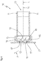
- the air vent according to the invention is in the Figures 1 to 4 as well as 7 and 8 shown in its entirety and given the overall reference numeral 10.
- the Figures 5 and 6th show the operating principle of the air vent according to the invention.
- the air vent 10 is shown, which has a housing 11 which forms an air outflow opening 12 and an air inflow opening 13.
- a housing 11 which forms an air outflow opening 12 and an air inflow opening 13.
- the housing 11 extends from the air inflow opening 13 to the air outflow opening 12 parallel to an air flow L (see Figures 2 to 8 ) a housing longitudinal axis 14.
- air-conducting fins 15 are arranged in the housing.
- the air-conducting lamellas 15 have both a lamella edge 17 close to the air outlet opening and a lamella edge 18 remote from the air outlet opening.
- the air flow L leaving the air outflow opening 12 is directed by means of the air-conducting fins 15.
- the air-conducting lamellae 15 each enclose a lamella angle ⁇ with the housing axis 14.
- the air-conducting fins 15 are rigidly and fan-like arranged in the housing 11, as is customary for a defroster is. This arrangement is used for a fan-like flow to the windshield, for example to dry off condensate that occurs there (not shown).
- an air vent 10 for vehicle interior ventilation which has air-conducting fins 15 which are aligned parallel to one another and which are movably arranged in the housing 11 by means of a pivot axis 16.
- the pivot axis 16 essentially coincides with the lamella edge 17 close to the air outflow opening.
- the air-conducting lamellae 15 are based on a control component 20 (see Figure 1 ) pivotable in the housing 11.
- the air-conducting fins 15 are combined to form a group of fins.
- the slat angle ⁇ is dependent on the alignment of the air-conducting slats 15 in the housing 11.
- the air vent 10 can have a second group of lamellae in addition to the first air-guiding lamella group, the air-guiding lamellae 15 of the second lamella group being arranged orthogonally to the air-guiding lamellae 15 of the first lamella group in the housing 11.
- the air outlet opening 12 of the air outlet 10 is in the Figure 2 or in the Figures 3 to 8 provided with an expanded metal cover 21.
- FIG. 3 and 4th a second embodiment of the air vent 10 is shown.
- the air-conducting fins 15 of this air vent 10 are movably arranged in the housing 11.
- the air-conducting fins 15 are arranged parallel to the housing longitudinal axis 14.
- the air flow L is here influenced exclusively by the expanded metal cover 21 in its outflow direction. This deflection of the air flow L is shown by the directional arrow P.
- the air-conducting slats are pivoted relative to the housing longitudinal axis 14 and include a slat angle ⁇ greater than 0 °.
- the air flow L is flowed to the expanded metal cover 21 so that the air flow L leaves the expanded metal cover 21 in accordance with the arrow P.
- both the air-conducting lamellae 15 and the expanded metal cover 21 influence the air flow L leaving the expanded metal cover 21 in its exit direction.
- the expanded metal cover 21 is shown excerpts and greatly enlarged.
- This Figures 5 and 6th show the working principle of the expanded metal cover.
- the expanded metal cover 21 has openings designed as meshes 22, which are bordered by webs 23. These webs 23 run obliquely into the plug-in metal cover 21.
- the webs 23 form web walls 24 which enclose web wall angles ⁇ with the housing longitudinal axis 14.
- the web wall angle dimension is greater than 0 ° and less than 90 °.
- the web wall angles ⁇ have a dimension of 20 ° to 70 °.
- the web wall angles ⁇ are approximately 45 °.
- the web wall angles ⁇ of the web walls 24 of the expanded metal cover 21 have an amount of a first angle.
- the web wall angles ⁇ are approx. 45 ° with respect to the housing longitudinal axis 14.
- the air flow L which comes from the air inlet opening 13, is aligned parallel to the housing longitudinal axis, flows onto the web walls 24 of the expanded metal cover 21.
- the prepared air flow L is now additionally directed by the web wall angle ⁇ .
- the resultant is thus approximately 45 °.
- the direction of the air flow L leaving the expanded metal cover 21 is shown with the aid of the directional arrow P.
- the air flow direction of the air vent 10 is shown with the arrow X, the air flow L experiencing a first deflection with respect to the housing longitudinal axis 14. In this embodiment the deflection is approx. 30 °.
- the prepared air stream L then flows through the web walls 24 of the expanded metal cover 21.
- the web wall angles ⁇ of the web walls 24 also have an angular value. In this specific exemplary embodiment, the web wall angles ⁇ are approximately 45 °.
- the air flow L experiences a second orientation based on the expanded metal cover 21, so that the resultant leaves the expanded metal cover 21 in accordance with the directional arrow P shown.
- FIG. 7 a further embodiment of the air vent 10 is shown.
- This embodiment shows an expanded metal cover 21 arranged on the air outflow opening 12 in a roll-shaped convex manner.
- the convex curvature of the expanded metal cover 21 has a plane of curvature K which is aligned parallel to the pivot axis 16 of the air-conducting lamellae 15.
- the air-conducting lamellae 15 of the air vent 10 are arranged in the housing 11 longitudinally parallel to the housing, so that the air flow L is directed parallel to the housing longitudinal axis 14 onto the convexly curved expanded metal cover 21.
- the web wall angle of the web walls 24 (not shown) (see Figure 5 and 6th ) increases with increasing distance from the housing longitudinal axis 14.
- the web walls 24 spread the air flow L due to the different web wall angles ⁇ in such a way that the air flow L leaving the expanded metal cover 21 is released in a fan-like manner into the motor vehicle interior (not shown). In this way, the passengers or a windshield can be blown with air over a large area.
- the spread of the air flow exiting in a fan-like manner remains identical, but is altogether changed in its outflow position from the expanded metal cover 21.
- Such an air vent 10 is used for the individual adjustment of the passenger in order to provide an optimal feel-good atmosphere.
- the expanded metal cover 21 is not convex in the shape of a cylinder, but rather oval-convex, whereby a modified fan spreading of the air flow L is possible.
- the expanded metal cover 21 is curved in a concave shape.
- This concave curvature of the expanded metal cover 21 has a plane of curvature K which is aligned parallel to the pivot axis 16 of the air-conducting lamellae 15.
- the air-conducting fins 15 behind the expanded metal cover 21 are aligned parallel to the housing axis, so that the air flow L on the air-conducting fins 15 is also arranged parallel to the housing axis.
- the cylindrical, concavely curved expanded metal cover 21 aligns the air flow L in accordance with the respective web wall angles ⁇ of the expanded metal cover 21 such that the air flow L leaving the expanded metal cover 21 exits the expanded metal cover 21 in a linear manner.
- This linearly exiting air flow L which is shown by the arrow P, can, for example, be directed specifically to a point on a windshield (not shown) covered with condensate in order to dry it off quickly and thus enables very precise and effective ventilation of the motor vehicle interior, not shown. Alternatively, people in the interior can be struck by a spot.
- An air vent 10 is also conceivable, the air flow L of which is directed from a combination of pivoted air-guiding lamellae 15 and a concavely curved plug-in metal cover 21.
- the air flow leaving the expanded metal cover 21 linearly can thus be directed in its entirety according to the degree of pivoting of the air-guiding lamellae 15.
- this embodiment also contributes to an optimized feel-good atmosphere for the passenger.
- the expanded metal cover 21 is not designed to be concave in the shape of a cylinder, but rather to be oval and concave, as a result of which modified flow patterns of the air flow L are possible.
- the air flow L deflected on the spherically convex expanded metal cover 21 is discharged conically into the passenger compartment and is used for a particularly large-area flow of air into the passenger compartment.
- the air flow L which, on the other hand, is deflected at a spherically concave expanded metal cover 21, is discharged conically into the passenger compartment and then merged at one point. This point-like deflected air flow L is used for particularly precise ventilation.
- the air vent 10 enables an individual flow of air to the passengers and the motor vehicle space, so that the air flow can be adapted to the respective situation.
Landscapes
- Physics & Mathematics (AREA)
- Thermal Sciences (AREA)
- Engineering & Computer Science (AREA)
- Mechanical Engineering (AREA)
- Air-Flow Control Members (AREA)
- Air-Conditioning For Vehicles (AREA)
Abstract
Description
- Die Erfindung betrifft einen Luftausströmer für den Innenraum eines Kraftfahrzeugs,
- mit einem Gehäuse, welches eine Gehäuselängsachse aufweist,
- mit einer vom Gehäuse ausgebildeten Luftaustrittsöffnung,
- mit einer den aus der Luftaustrittöffnung verlassenden Luftstrom ausrichtenden Lamelle, welche im Gehäuse angeordnet ist.
- Derartige Luftausströmer sind aus dem druckschriftlich nicht belegbaren Stand der Technik hinlänglich bekannt und dienen der Luftzufuhr in den Kraftfahrzeuginnenraum, um beispielsweise Kondensat an einer Windschutzscheibe abzutrocknen. Solche als Defroster ausgebildeten Luftausströmer weisen Luftausströmöffnungen und wenigstens eine feststehende Lamelle auf, welche einen Luftstrom auf die Windschutzscheibe ausrichtet und hinsichtlich ihrer Leistungsfähigkeit strengen gesetzlichen Normen unterliegen.
- Aus der
EP 3 164 280 B1 sind beispielsweise auch gattungsgemäße Luftausströmer bekannt, welche horizontale und vertikale Lamellen aufweisen, die in einem Gehäuse schwenkbeweglich und kreuzweise ineinander geschachtelt gelagert sind. Derartige Luftausströmer sind beispielsweise in der Armaturentafel oder der Seitenverkleidung im Fahrzeuginnenraum installiert und ermöglichen es, den Passagieren den Luftstrom gezielt und komfortabel auszurichten. - Aufgrund des zukünftigen teil- und vollautonomen Fahrens, rückt in der Fahrzeugindustrie die ästhetische Ausgestaltung des Fahrzeuginnenraumes seit geraumer Zeit in den Vordergrund, um für den Fahrgast eine Wohlfühlatmosphäre zu schaffen. Als besonders ästhetisch und qualitativ hochwertig werden dabei einheitliche Oberflächen wahrgenommen, die einer optischen Vereinheitlichung des Innenraumdesigns dienen.
Die aus dem Stand der Technik bekannten Luftausströmer weisen allerdings Luftausströmöffnungen aus, wodurch die gewünschte optische Einheitlichkeit des Armaturenbrettes aufgelöst wird und der ästhetische Gesamteindruck des Fahrzeuginnenraumes deutlich vermindert ist. - Neben der optischen Uneinheitlichkeit, unterliegen die Luftausströmer der Gefahr, dass zuvor auf dem Armaturenbrett abgelegt Fremdkörper unbeabsichtigt in die Luftausströmöffnungen gelangen können und somit die Funktionalität der Luftausströmer erheblich einschränkt ist. Ein Entfernen dieser Fremdkörper ist mit großem Aufwand verbunden.
- Es ist deshalb die Aufgabe der Erfindung, einen Luftausströmer zu schaffen, der bei vollständiger Funktionalität die Einhaltung der gesetzlich vorgeschriebenen Leistungsfähigkeitsnorm erfüllt und das Eindringen von Fremdkörpern verhindern sowie die gestiegenen optischen Anforderungen an das Innenraumdesign berücksichtigt.
- Aus dem nicht gattungsgemäßen Stand der Technik sind beispielsweise Streckmetalle und Streckmetallen nachgeahmte Strukturen, beispielsweise aus Kunststoff, bekannt. Diese dienen beispielsweise der großflächigen Abdeckung des Armaturenbrettes oder von Lautsprecheröffnungen und schaffen somit eine einheitliche Oberfläche, die ästhetisch besonders ansprechend ist. Die Abdeckung von Luftausströmern wird durchgängig vermieden, weil diese den gerichteten Luftstrom in einen diffusen Luftstrom wandelt. Im Bereich der Defroster kann somit nicht die vorgeschriebene gesetzliche Leistungsnorm erfüllt werden. Auch im Bereich andere Luftausströmer verzichtet man auf die Abdeckung aus Streckmetall oder Streckmetallen nachgeahmten Strukturen.
- Gelöst wird die Aufgabe von einem Luftausströmer für den Innenraum eines Kraftfahrzeuges mit den Merkmalen des Anspruches 1, insbesondere mit dessen kennzeichnenden Merkmalen, wonach die Luftaustrittsöffnung des Luftausströmers mit einer Streckmetallabdeckung versehen ist, welche Maschen aufweist, die von Stegen eingefasst sind, welche Stegwände ausbilden, die in einem Winkel zur Gehäuselängsachse stehen und wonach die wenigstens eine Lamelle zum Ausrichten des Luftstroms in einem Winkel zur Gehäuselängsachse angeordnet ist und wenigstens eine streckmetallnahe und ein streckmetallferne Kante aufweist, wobei die streckmetallnahe Kante derart dicht an der Streckmetallabdeckung angeordnet ist, dass der die Streckmetallabdeckung verlassende Luftstrom im Wesentlichen definiert gerichtet ist, wobei sich die Richtung des austretenden Luftstroms als Resultierende des Lamellenwinkels und des Stegwandwinkels ergibt.
- Die Erfindung überwindet das Vorurteil des Standes der Technik, dass Streckmetalle nicht luftrichtend wirken. Überraschend hat es sich herausgestellt, dass der gerichtete Luftstrom trotz Durchströmens des Streckmetalls seine definierte Ausrichtung beibehält. In aufwendigen Versuchen hat sich gezeigt, dass der gerichtete Luftstrom nach Durchtritt durch das Streckmetall erhalten bleibt, wenn die streckmetallnahe Kante der Lamelle bis auf ein der Montage geschuldetes Passungsspiel an die Streckmetallabdeckung herangeführt ist. Die Leistungsfähigkeit eines Defrosters wird somit durch die Anordnung der Steckmetallabdeckung an der Luftausströmöffnung des Luftausströmers nicht herabgesetzt und entspricht weiterhin den gesetzlich vorgeschriebenen Anforderungen.
- Der Luftausströmer gemäß
EP 3 164 280 B1 lässt sich ebenfalls mit einer derartigen Streckmetallabdeckung versehen. Auch hier verbleibt der Luftstrom nach dem Durchtritt aus der Streckmetallabdeckung gerichtet, wenn darauf geachtet wird, dass die streckmetallnahe Kante der Lamelle derart dicht an die Streckmetallabdeckung herangeführt ist, dass lediglich das der Montage geschuldete Passungsspiel zwischen Streckmetall und streckmetallnaher Kante der Lamelle verbleibt. Somit überwindet die Erfindung die unverrückbare Erkenntnis, dass ein die Streckmetallabdeckung durchströmender Luftstrom nicht ausrichtbar ist. - Die Erfindung erlaubt nunmehr die Gefahr des Eindringens von Fremdkörpern zu verhindern. Die Maschen der Streckmetallabdeckung sind derart eng aneinander angeordnet, dass in die Öffnungen allerhöchstens winzige, die Funktionalität des Luftausströmers nicht beeinträchtigende Fremdkörper, eindringen.
- Besonders vorteilhaft ist die Streckmetallabdeckung gleichwohl aufgrund ihrer Struktur. Sie ist ästhetisch ansprechend und erfüllt die hohen optischen Anforderungen der Fahrzeugindustrie an den Fahrzeuginnenraum. Da nun auch Defroster und andere Luftausströmer problemlos ohne Funktionalitätsverlust mit dem Streckmetall abdeckt werden können, kann das komplette Armaturenbrett großflächig und einheitlich ausgestaltet werden, wodurch das gesamtheitliche Innenraumdesign des Kraftfahrzeuges optimiert ist.
- In einer bevorzugten Ausführungsform ist denkbar, dass die wenigstens eine Lamelle um eine Achse schwenkbar im Gehäuse angeordnet ist, sodass der Lamellenwinkel gegenüber der Gehäuselängsachse veränderbar ist. Zudem ist es auch vorgesehen, dass die Schwenkachse der Lamellen derart streckmetallnah angeordnet ist, dass der durch die Schwenkbewegung der Lamellen zunehmende Abstand zwischen Lamellenkante und Streckmetallabdeckung noch einen die Abdeckung gerichtet verlassenden Luftstrom ermöglicht.
- Der Luftstrom wird somit zunächst mittels der schwenkbaren Lamellen im Gehäuseinnenraum ausgerichtet und anschließend an der Streckmetallabdeckung umgeleitet ohne dass Verwirbelungen zwischen Lamelle und Streckmetallabdeckung auftreten. Der Luftstrom wird somit gerichtet in den Innenraum des Kraftfahrzeuges geleitet.
- Weiterhin ist es vorgesehen, dass die streckmetallnahe Kante in einer Lamellenkante ausläuft und dass die Schwenkachse im Wesentlichen mit der Lamellenkante zusammenfällt. Besonders vorteilhaft an dieser Ausführungsform ist, dass der Abstand zwischen Lamellenkante und Streckmetallabdeckung trotz Schwenkbewegung der Lamelle auf ein Minimum reduziert ist. Der die Streckmetallabdeckung verlassende Luftstrom ist somit ausrichtbar.
- Denkbar ist es zudem, dass mehrere parallel zueinander ausgerichtete Lamellen im Gehäuse angeordnet sind. Eine Ausrichtung des Luftstromes mittels mehrerer parallel zueinander ausgerichteten Lamellen in einem Gehäuse ist vorteilhaft, da der Luftstrom besonders feingliedrig ausgerichtet aus dem Luftausströmer entlassen werden kann.
- In einer weiteren Ausführungsform des Luftausströmers ist vorteilhafterweise vorgesehen, dass die Streckmetallabdeckung eine konvexe oder eine konkave Krümmung aufweist, deren Krümmungsebene zur Schwenkachse der Lamelle parallel ausgerichtet ist. Die Krümmung der Streckmetallabdeckung kann beispielsweise konvex oder konkav sein und einen steten Radius aufweisen, wobei die Krümmung dann walzenförmig ausgebildet ist. Zudem ist auch eine Krümmung mit unstetem Radius, beispielsweise mit ovalem Verlauf, vorstellbar.
- Sowohl die konvexe als auch die konkave Krümmung der Streckmetallabdeckung löst eine Luftumlenkung des verlassenden Luftstroms aus, wodurch neuartige Strömungsbilder generiert werden können. Der an einer konvex gekrümmten Streckmetallabdeckung umgelenkte Luftstrom wird fächerartig in den Personeninnenraum entlassen. Eine derartige Auffächerung bedingt eine großflächige Beströmung der Passagiere oder der Windschutzscheibe. Somit kann in kurzer Zeit eine größere Fläche mit Luft bedeckt werden. Die Intensität des Luftstroms kann dabei abnehmen und ist dann besonders angenehm für den Fahrgast.
- Im Gegensatz dazu bedingt eine konkav gekrümmte Streckmetallabdeckung, dass der austretende Luftstrom gebündelt wird und somit eine präzise, linienförmige Ausrichtung des Luftstromes möglich ist. Dieser linienförmig austretende Luftstrom kann beispielsweise gezielt auf eine mit Kondensat bedeckte Stelle an der Windschutzscheibe gerichtet werden, um diese schnell abzutrocknen. Die konkave gekrümmte Streckmetallabdeckung gewährleistet somit eine präzise und effektive Belüftung des Fahrgastinnenraumes.
- Es ist weiterhin vorgesehen, dass der Luftstrom mittels einer Kombination aus der gekrümmten Streckmetallabdeckung und der hinter der gekrümmten Streckmetallabdeckung angeordneten Lamellen gerichtet wird. Diese Kombination ermöglicht eine individuelle Ausrichtung des Luftstromes für den Fahrgast, wobei der Luststrom leicht an jede Situation angepasst werden kann.
- Denkbar ist zudem, dass die Stegwände der gekrümmten Streckmetallabdeckung jeweils eine Ebene aufspannen und dass diese jeweils die Gehäuselängsachse schneiden, wobei die jeweiligen Schnittwinkel von Ebene und Gehäuselängsachse mit zunehmendem Abstand der jeweiligen Stegwände von der Gehäuselängsachse zunehmen.
- Angedacht ist außerdem, dass der Betrag der Schnittwinkeländerung von Schnittwinkel zu Schnittwinkel konstant ist, wie bei einer walzenförmigen Ausgestaltung der Streckmetallabdeckung. Allerdings ist es auch möglich, dass der Betrag der Schnittwinkeländerung von Schnittwinkel zu Schnittwinkel unterschiedlich ist, wie bei einer gekrümmten Steckmetallabdeckung mit unstetem Radius.
- Zudem sieht ein Ausführungsbeispiel der Erfindung vor, dass der Luftausströmer als Defroster für die Windscheibe eines Kraftwagens ausgebildet ist. Allerdings sind auch andersartige Luftausströmer vorstellbar.
- Weitere Vorteile der Erfindung sowie ein besseres Verständnis derselben ergeben sich aus der nachfolgenden Beschreibung mehrerer Ausführungsbeispiele. Es zeigen:
- Figur 1:
- perspektivische Übersichtsdarstellung eines Luftausströmers mit Streckmetallabdeckung,
- Figur 2:
- Schnittdarstellung einer ersten Ausführungsform des Luftausströmers gemäß Schnittlinien A-A in
Figur 1 mit starren luftleitenden Lamellen, - Figur 3:
- Schnittdarstellung einer zweiten Ausführungsform des Luftausströmers gemäß Schnittlinie A-A in
Figur 1 mit schwenkbaren luftleitenden Lamellen, - Figur 4:
- Schnittdarstellung der zweiten Ausführungsform des Luftausströmers gemäß Schnittlinie A-A in
Figur 1 mit gegenüber einer Gehäuseachse verschwenkten luftleitenden Lamellen, - Figur 5:
- Vergrößerte Ausschnittdarstellung einer Streckmetallabdeckung zur Prinzipdarstellung des Luftausströmers mit gehäuseachsparallelem Luftstrom,
- Figur 6:
- Vergrößerte Ausschnittdarstellung der Streckmetallabdeckung zur Prinzipdarstellung des Luftausströmers mit abgelenktem Luftstrom,
- Figur 7:
- Schnittdarstellung einer dritten Ausführungsform mit konvex gekrümmter Streckmetallabdeckung,
- Figur 8:
- Schnittdarstellung einer vierten Ausführungsform des Luftausströmers mit konkav gekrümmter Streckmetallabdeckung.
- Der erfindungsgemäße Luftausströmer ist in den
Figuren 1 bis 4 sowie 7 und 8 in seiner Gesamtheit dargestellt und insgesamt mit dem Bezugszeichen 10 versehen. DieFiguren 5 und6 zeigen das Wirkprinzip des erfindungsgemäßen Luftausströmers. - In den
Figuren 1 bis 4 sowie 7 und 8 ist der Luftausströmer 10 gezeigt, welcher ein Gehäuse 11 aufweist, das eine Luftausströmöffnung 12 und eine Lufteinströmöffnung 13 ausbildet. Im Gehäuse 11 erstreckt sich von der Lufteinströmöffnung 13 bis zu der Luftausströmöffnung 12 parallel zu einem Luftstrom L (sieheFigur 2 bis 8 ) eine Gehäuselängsachse 14. - In den
Figuren 1 bis 8 sind im Gehäuse 11 luftleitende Lamellen 15 angeordnet. Die luftleitenden Lamellen 15 weisen sowohl eine luftausströmöffnungsnahe Lamellenkante 17 als auch eine luftausströmöffnungsferne Lamellenkante 18 auf. Mittels der luftleitenden Lamellen 15 wird der die Luftausströmöffnung 12 verlassende Luftstrom L gerichtet. Zudem schließen die luftleitenden Lamellen 15 mit der Gehäuseachse 14 jeweils einen Lamellenwinkel α ein. - In der
Figur 2 sind die luftleitenden Lamellen 15 starr und fächerartig im Gehäuse 11 angeordnet, wie es üblicherweise für einen Defroster üblich ist. Diese Anordnung dient der fächerartigen Beströmung der Windschutzscheibe, um beispielsweise dort auftretendes Kondensat abzutrocknen (nicht dargestellt). - In den
Figuren 3 bis 8 ist ein Luftausströmer 10 für die Kraftfahrzeuginnenraumbelüftung dargestellt, welcher zueinander parallel ausgerichtete, luftleitenden Lamellen 15 aufweist, die mittels einer Schwenkachse 16 beweglich im Gehäuse 11 angeordnet sind. Die Schwenkachse 16 fällt im Wesentlichen mit der luftausströmöffnungsnahen Lamellenkante 17 zusammen. Die luftleitenden Lamellen 15 sind anhand eines Steuerbauteils 20 (sieheFigur 1 ) im Gehäuse 11 verschwenkbar. Die luftleitenden Lamellen 15 sind zu einer Lamellengruppe zusammengefasst. - Der Lamellenwinkel α ist von der Ausrichtung der luftleitenden Lamellen 15 im Gehäuse 11 abhängig.
- An dieser Stelle sei darauf hingewiesen, dass der Luftausströmer 10 neben der ersten luftleitenden Lamellengruppe eine zweite Lamellengruppe aufweisen kann, wobei die luftleitenden Lamellen 15 der zweiten Lamellengruppe orthogonal zu den luftleitenden Lamellen 15 der ersten Lamellengruppe im Gehäuse 11 angeordnet sind.
- Die Luftausströmöffnung 12 des Luftausströmers 10 ist in der
Figur 2 beziehungsweise in denFiguren 3 bis 8 mit einer Streckmetallabdeckung 21 versehen. - In den
Figuren 3 und4 wird eine zweite Ausführungsform des Luftausströmers 10 gezeigt. Die luftleitenden Lamellen 15 dieses Luftausströmers 10 sind beweglich im Gehäuse 11 angeordnet. - In der
Figur 3 sind die luftleitenden Lamellen 15 parallel zur Gehäuselängsachse 14 angeordnet. Der Luftstrom L wird hier ausschließlich durch die Streckmetallabdeckung 21 in seiner Ausströmrichtung beeinflusst. Diese Ablenkung des Luftstroms L wird durch den Richtungspfeil P dargestellt. - In der
Figur 4 sind die luftleitenden Lamellen gegenüber der Gehäuselängsachse 14 verschwenkt und schließt einen Lamellenwinkel α größer 0° ein. Hierdurch wird der Luftstrom L vorgerichtet an die Streckmetallabdeckung 21 geströmt, so dass der Luftstrom L entsprechend des Pfeiles P die Streckmetallabdeckung 21 verlässt. In dieser Ausführungsform beeinflussen sowohl die luftleitenden Lamellen 15 als auch das Streckmetallabdeckung 21 den die Streckmetallabdeckung 21 verlassenden Luftstrom L in seiner Austrittrichtung. - Im Folgenden wird nun die Funktionsweise des erfindungsgemäßen Luftausströmers anhand der
Figuren 5 und6 erläutert:
In denFiguren 5 und6 ist die Streckmetallabdeckung 21 ausschnittsweise und stark vergrößert dargestellt. DieseFiguren 5 und6 zeigen das Wirkprinzip der Streckmetallabdeckung. Es ist deutlich zu erkennen, dass die Streckmetallabdeckung 21 als Maschen 22 ausgebildete Öffnungen aufweist, welchen von Stegen 23 eingefasst sind. Diese Stege 23 sind schräg verlaufend in der Steckmetallabdeckung 21 eingearbeitet. Die Stege 23 bilden Stegwände 24 aus, die Stegwandwinkel β mit der Gehäuselängsachse 14 einschließen. Das Stegwandwinkelmaß ist größer 0° und kleiner 90° In einer bevorzugten Ausführungsform haben die Stegwandwinkel β ein Maß von 20° bis 70°. In dem dargestellten Ausführungsbeispiel betragen die Stegwandwinkel β ca. 45°. - In der
Figur 5 ist die Luftanströmrichtung des Luftausströmers 10 mit dem Pfeil X gezeigt, welcher gehäuseachsparallel ausgerichtet ist. - Die Stegwandwinkel β der Stegwände 24 der Streckmetallabdeckung 21 haben einen Betrag eines ersten Winkels. Die Stegwandwinkel β betragen in diesem konkreten Ausführungsbeispiel ca. 45° in Bezug auf die Gehäuselängsachse 14. Der Luftstrom L, welcher von der Lufteinströmöffnung 13 kommend gehäuselängsachsparallel ausgerichtet ist, wird an die Stegwände 24 der Streckmetallabdeckung 21 geströmt. An diesen Stegwänden 24 wird der vorgerichtet Luftstrom L nun zusätzlich durch den Stegwandwinkel β gerichtet. In diesem Ausführungsbeispiel beträgt die Resultierende somit ca. 45°. Die Richtung des die Streckmetallabdeckung 21 verlassenden Luftstroms L ist anhand des Richtungspfeiles P dargestellt.
- In der
Figur 6 ist die Luftanströmrichtung des Luftausströmers 10 mit dem Pfeil X gezeigt, wobei der Luftstrom L eine erste Ablenkung in Bezug auf die Gehäuselängsachse 14 erfährt. In diesem Ausführungsbeispiel beträgt die Ablenkung ca. 30°. Der vorgerichtete Luftstrom L beströmt anschließend die Stegwände 24 der Streckmetallabdeckung 21. Die Stegwandwinkel β der Stegwände 24 haben ebenfalls einen Winkelbetrag. In diesem konkreten Ausführungsbeispiel betragen die Stegwandwinkel β ca. 45°. Der Luftstrom L erfährt hier eine zweite Ausrichtung anhand der Streckmetallabdeckung 21, so dass die Resultierende entsprechend des gezeigten Richtungspfeiles P die Streckmetallabdeckung 21 verlässt. - In der
Figur 7 ist eine weitere Ausführungsform des Luftausströmers 10 dargestellt. Diese Ausführungsform zeigt eine an der Luftausströmöffnung 12 angeordnete walzenförmig konvex ausgebildete Streckmetallabdeckung 21. Die konvexe Krümmung der Streckmetallabdeckung 21 weist eine Krümmungsebene K auf, welche zu der Schwenkachse 16 der luftleitenden Lamellen 15 parallel ausgerichtet ist. - Die luftleitenden Lamellen 15 des Luftausströmers 10 sind im Gehäuse 11 gehäuselängsachparallel angeordnet, so dass der Luftstrom L parallel zur Gehäuselängsachse 14 vorgerichtet auf die konvex gekrümmte Streckmetallabdeckung 21 geleitet wird.
- Das Stegwandwinkelmaß der nicht dargestellten Stegwände 24 (siehe
Figur 5 und6 ) nimmt mit zunehmendem Abstand von der Gehäuselängsachse 14 zu. Die Stegwände 24 die in gleichem Abstand zur Gehäuselängsachse 14 in der Streckmetallabdeckung 21 eingebracht sind, weisen ein identisches Stegwandwinkelmaß auf. - Die Stegwände 24 spreizen den Luftstrom L aufgrund der unterschiedlichen Stegwandwinkel β nun derart auf, dass der die Streckmetallabdeckung 21 verlassende Luftstrom L fächerartig in den nicht dargestellten Kraftfahrzeuginnenraum entlassen wird. So können die Passagiere oder eine Windschutzscheibe großflächig mit Luft beströmt werden.
- Wird der Luftstrom L nun zusätzlich an den zur Gehäuseachse 14 verschwenkten luftleitenden Lamellen 15 vorgerichtet, bleibt der fächerartig austretende Luftstrom in seiner Spreizung zwar identisch, wird allerdings insgesamt in seiner Ausströmlage aus der Streckmetallabdeckung 21 verändert. Eine derartige Luftausströmer 10 dient der individuellen Anpassung des Passagiers, um eine optimale Wohlfühlatmosphäre bereitzustellen.
- In einer weiteren Ausführungsform ist es denkbar, dass die Streckmetallabdeckung 21 nicht walzenförmig konvex, sondern oval konvex ausgebildet ist, wodurch eine abgewandelte Fächerspreizung des Luftstrom L möglich ist.
- In der
Figur 8 ist eine weitere Ausführungsform des Luftausströmers 10 dargestellt. Die Streckmetallabdeckung 21 ist walzenförmig konkav gekrümmt. Diese konkave Krümmung der Streckmetallabdeckung 21 weist eine Krümmungsebene K auf, welche zu der Schwenkachse 16 der luftleitenden Lamellen 15 parallel ausgerichtet ist. - Auch hier nimmt das Stegwandwinkelmaß der nicht dargestellten Stegwände 24 (siehe
Figur 5 und6 ) mit zunehmendem Abstand von der Gehäuselängsachse 14 zu. Stegwände 24 gleicher Beabstandung zur der Gehäuselängsachse 14 weisen identische Stegwandwinkelmaße auf. - Die luftleitenden Lamellen 15 hinter der Streckmetallabdeckung 21 sind gehäuseachsparallel ausgerichtet, sodass auch der Luftstrom L an den luftleitenden Lamellen 15 gehäuseachsparallel vorgerichtet wird. Die walzenförmige, konkav gekrümmte Streckmetallabdeckung 21 richtet den Luftstrom L nun entsprechend der jeweiligen Stegwandwinkeln β der Streckmetallabdeckung 21 derart aus, dass der die Streckmetallabdeckung 21 verlassenden Luftstrom L aus der Streckmetallabdeckung 21 linienförmig zusammengeführt austritt. Dieser linienförmig austretende Luftstrom L, welcher durch den Pfeil P dargestellt ist, kann beispielsweise gezielt auf eine mit Kondensat bedeckte Stelle an einer nicht dargestellten Windschutzscheibe gerichtet werden, um diese schnell abzutrocknen und ermöglicht somit eine sehr präzise und effektive Belüftung des nicht dargestellten Kraftfahrzeuginnenraumes. Alternativ können Personen im Innenraum spotartig angeströmt werden.
- Es ist auch ein Luftausströmer 10 vorstellbar, dessen Luftstrom L aus einer Kombination von verschwenkten luftleitenden Lamellen 15 und einer konkav gekrümmten Steckmetallabdeckung 21 gerichtet wird. Der linienförmig die Streckmetallabdeckung 21 verlassende Luftstrom kann somit in seiner Gesamtheit entsprechend des Schwenkgrades der luftleitenden Lamellen 15 gerichtet werden. Entsprechend des Luftausströmers 10 der
Figur 7 trägt auch dieses Ausführungsbeispiel zu einer optimierten Wohlfühlatmosphäre des Fahrgastes bei. - Bei einer weiteren Ausführungsform ist es auch möglich, dass die Streckmetallabdeckung 21 nicht walzenförmig konkav, sondern oval konkav ausgebildet ist, wodurch abgewandelte Strömungsbilder des Luftstrom L möglich sind.
- Weiterhin ist es möglich, die Streckmetallabdeckung 21 konvex oder konkav sphärisch auszubilden.
- Der an der sphärisch konvex ausgebildeten Streckmetallabdeckung 21 abgelenkte Luftstrom L, wird kegelförmig in den Fahrgastinnenraum entlassen und dient einer besonders großflächigen Beströmung des Fahrgastinnenraumes.
- Der Luftstrom L, welcher hingegen an einer sphärisch konkaven ausgebildeten Streckmetallabdeckung 21 abgelenkt wird, wird kegelförmig in den Fahrgastinnenraum entlassen und anschließend an einem Punkt zusammengeführt. Dieser punktfömig abgelenkte Luftstrom L dient einer besonders präzisen Belüftung.
- Insgesamt ermöglicht der erfindungsgemäße Luftausströmer 10 eine individuelle Beströmung der Fahrgäste und des Kraftfahrzeugraumes, so dass die Luftausströmung an die jeweilige Situation angepasst werden kann.
-
- 10
- Luftausströmer
- 11
- Gehäuse
- 12
- Luftausströmöffnung
- 13
- Luftausströmöffnung
- 14
- Gehäuselängsachse
- 15
- luftleitende Lamelle
- 16
- Schwenkachse
- 17
- luftausströmöffnungsnahe Lamellenkante
- 18
- luftausströmöffnungsferne Lamellenkante
- 20
- Steuerbauteil
- 21
- Streckmetallabdeckung
- 22
- Masche
- 23
- Steg
- 24
- Stegwand
- K
- Krümmungsebene
- L
- Luftstrom
- P
- Richtungspfeil
- X
- Richtungspfeil
- α
- Lamellenwinkel
- β
- Stegwandwinkel
Claims (10)
- Luftausströmer (10) für den Innenraum eines Kraftfahrzeugs,- mit einem Gehäuse (11), welches eine Gehäuselängsachse (14) aufweist,- mit einer vom Gehäuse (11) ausgebildeten Luftaustrittsöffnung (12),- mit einer den aus der Luftaustrittöffnung (12) verlassenden Luftstrom (L) ausrichtenden Lamelle (15), welche im Gehäuse (11) angeordnet ist, dadurch gekennzeichnet, dass die Luftaustrittsöffnung (12) des Luftausströmers (10) mit einer Streckmetallabdeckung (21) versehen ist, welche Maschen (22) aufweist, die von Stegen (23) eingefasst sind, welche Stegwände (24) ausbilden, die in einem Winkel zur Gehäuselängsachse (14) stehen und dadurch gekennzeichnet, dass die wenigstens eine Lamelle (15) zum Ausrichten des Luftstroms (L) in einem Winkel zur Gehäuselängsachse (14) angeordnet ist und wenigstens eine streckmetallnahe und ein streckmetallferne Kante (17, 18) aufweist, wobei- die streckmetallnahe Kante (17) derart dicht an der Streckmetallabdeckung (21) angeordnet ist, dass der die Streckmetallabdeckung (21) verlassende Luftstrom (L) im Wesentlichen definiert gerichtet ist, wobei sich die Richtung des austretenden Luftstroms (L) als Resultierende des Lamellenwinkels (a) und des Stegwandwinkels (β) ergibt.
- Luftausströmer (10) nach Anspruch 1, dadurch gekennzeichnet, dass die wenigstens eine Lamelle (15) um eine Achse (16) schwenkbar im Gehäuse (11) angeordnet ist, sodass der Lamellenwinkel (a) gegenüber der der Gehäuselängsachse (14) veränderbar ist.
- Luftausströmer (10) nach Anspruch 2, dadurch gekennzeichnet, dass die Schwenkachse (16) der Lamelle (15) derart streckmetallnah angeordnet ist, dass der durch die Schwenkbewegung der Lamelle (15) zunehmende Abstand zwischen Lamellenkante (17) und Streckmetallabdeckung (21) noch einen die Streckmetallabdeckung (21) gerichtet verlassenden Luftstrom (L) ermöglicht.
- Luftausströmer (10) nach Anspruch 1 und 2, dadurch gekennzeichnet, dass die streckmetallnahe Kante (17) in einer Lamellenkante ausläuft und dass die Schwenkachse (16) im Wesentlichen mit der Lamellenkante (17) zusammenfällt.
- Luftausströmer (10) nach einem der vorhergehenden Ansprüche, dass mehrere parallel zueinander ausgerichtete Lamellen (15) im Gehäuse (11) angeordnet sind.
- Luftausströmer (10) nach einem der vorhergehenden Ansprüche, dadurch gekennzeichnet, dass die Streckmetallabdeckung (21) eine konvexe oder eine konkave Krümmung aufweist, deren Krümmungsebene (K) zur Schwenkachse (16) der Lamelle (15) parallel ausgerichtet ist.
- Luftausströmer (10) nach Anspruch 6, dadurch gekennzeichnet, dass die Stegwände (24) der gekrümmten Streckmetallabdeckung (21) jeweils eine Ebene aufspannen und dass diese jeweils die Gehäuselängsachse (14) schneiden, wobei die jeweiligen Schnittwinkel von Ebene und Gehäuselängsachse (14) mit zunehmendem Abstand der jeweiligen Stegwand (24) von der Gehäuselängsachse (14) zunehmen.
- Luftausströmer (10) nach Anspruch 7, dadurch gekennzeichnet, dass der Betrag der Schnittwinkeländerung von Schnittwinkel zu Schnittwinkel konstant ist.
- Luftausströmer (10) nach Anspruch 7, dadurch gekennzeichnet, dass der Betrag der Schnittwinkeländerung von Schnittwinkel zu Schnittwinkel unterschiedlich ist.
- Luftausströmer (10) nach einem der vorhergehenden Ansprüche, dadurch gekennzeichnet, dass der Luftausströmer (10) als Defroster für die Windscheibe eines Kraftwagens ausgebildet ist.
Applications Claiming Priority (1)
| Application Number | Priority Date | Filing Date | Title |
|---|---|---|---|
| DE102019106086.9A DE102019106086B4 (de) | 2019-03-11 | 2019-03-11 | Luftausströmer für den Innenraum eines Kraftfahrzeuges |
Publications (2)
| Publication Number | Publication Date |
|---|---|
| EP3708395A1 true EP3708395A1 (de) | 2020-09-16 |
| EP3708395B1 EP3708395B1 (de) | 2021-10-13 |
Family
ID=69742794
Family Applications (1)
| Application Number | Title | Priority Date | Filing Date |
|---|---|---|---|
| EP20159833.1A Active EP3708395B1 (de) | 2019-03-11 | 2020-02-27 | Luftausströmer für den innenraum eines kraftfahrzeuges |
Country Status (4)
| Country | Link |
|---|---|
| US (1) | US20200290432A1 (de) |
| EP (1) | EP3708395B1 (de) |
| CN (1) | CN111688445B (de) |
| DE (1) | DE102019106086B4 (de) |
Families Citing this family (3)
| Publication number | Priority date | Publication date | Assignee | Title |
|---|---|---|---|---|
| EP3722126B1 (de) * | 2019-04-09 | 2023-06-07 | Volvo Car Corporation | Luftausströmer |
| EP4342699A4 (de) * | 2021-05-20 | 2025-02-12 | Zhejiang Smart Intelligence Technology Co., Ltd. | Klimatisierungsluftauslassvorrichtung und kraftfahrzeug |
| DE102025107587A1 (de) * | 2024-03-20 | 2025-09-25 | Illinois Tool Works Inc. | Luftausströmer für ein fahrzeug mit ausströmgitter sowie ausströmgitter für einen solchen luftausströmer |
Citations (4)
| Publication number | Priority date | Publication date | Assignee | Title |
|---|---|---|---|---|
| EP0566474A1 (de) * | 1992-04-16 | 1993-10-20 | Valeo Thermique Habitacle | Heizungs-, Belüftungs- und/oder Klimatisierungsvorrichtung für den Innenraum von Kraftfahrzeugen |
| FR2912085A1 (fr) * | 2007-02-05 | 2008-08-08 | Bourbon Automobile Soc Par Act | Buse de ventilation pour habitacle de vehicule automobile, notamment pour un appui tete de siege de vehicule automobile |
| WO2015074955A1 (de) * | 2013-11-21 | 2015-05-28 | Dr. Schneider Kunststoffwerke Gmbh | Lamelle und luftausströmer mit mindestens einer lamelle |
| EP3164280B1 (de) | 2014-08-07 | 2018-11-07 | GRAMMER Interior Components GmbH | Belüftungsvorrichtung |
Family Cites Families (12)
| Publication number | Priority date | Publication date | Assignee | Title |
|---|---|---|---|---|
| DE3837916A1 (de) * | 1988-11-09 | 1990-05-10 | Daimler Benz Ag | Luftauslassduese |
| JP3929347B2 (ja) * | 2002-04-24 | 2007-06-13 | 株式会社ニフコ | 空気吹き出し口の調節装置 |
| US20070093197A1 (en) * | 2005-10-26 | 2007-04-26 | Building Materials Investment Corporation | Peel and stick vents, soffits and ridges |
| DE102006026655A1 (de) | 2006-06-08 | 2007-12-13 | Daimlerchrysler Ag | Kraftfahrzeug-Bauteil mit einem wölbstrukturierten Lochblech |
| FR2902369B1 (fr) | 2006-06-16 | 2011-05-06 | Faurecia Interieur Ind | Systeme de ventilation forcee de l'habitacle d'un vehicule automobile, et planche de bord correspondante. |
| KR20130038564A (ko) | 2011-10-10 | 2013-04-18 | 현대모비스 주식회사 | 자동차의 에어벤트 장치 |
| DE102014101315A1 (de) * | 2013-10-30 | 2015-04-30 | Dr. Schneider Kunststoffwerke Gmbh | Luftdüse |
| DE202014002057U1 (de) * | 2014-03-11 | 2015-06-12 | GM GLOBAL TECHNOLOGY OPERATION LLC (n. d. Ges. d. Staates Delaware) | Luftausströmer |
| DE102015115530A1 (de) | 2015-09-15 | 2017-03-30 | Dr. Schneider Kunststoffwerke Gmbh | Multifunktionales und multidirektionales Belüftungssystem |
| JP2017159876A (ja) * | 2016-03-04 | 2017-09-14 | 豊和化成株式会社 | レジスタ |
| DE102017118450A1 (de) * | 2017-08-14 | 2019-02-14 | Illinois Tool Works Inc. | Luftausströmer für ein Fahrzeug |
| CN109367361A (zh) * | 2018-12-03 | 2019-02-22 | 江苏创导空调有限公司 | 一种出风口方向可调的车载空调 |
-
2019
- 2019-03-11 DE DE102019106086.9A patent/DE102019106086B4/de active Active
-
2020
- 2020-02-25 US US16/800,194 patent/US20200290432A1/en not_active Abandoned
- 2020-02-27 EP EP20159833.1A patent/EP3708395B1/de active Active
- 2020-03-11 CN CN202010166969.1A patent/CN111688445B/zh active Active
Patent Citations (4)
| Publication number | Priority date | Publication date | Assignee | Title |
|---|---|---|---|---|
| EP0566474A1 (de) * | 1992-04-16 | 1993-10-20 | Valeo Thermique Habitacle | Heizungs-, Belüftungs- und/oder Klimatisierungsvorrichtung für den Innenraum von Kraftfahrzeugen |
| FR2912085A1 (fr) * | 2007-02-05 | 2008-08-08 | Bourbon Automobile Soc Par Act | Buse de ventilation pour habitacle de vehicule automobile, notamment pour un appui tete de siege de vehicule automobile |
| WO2015074955A1 (de) * | 2013-11-21 | 2015-05-28 | Dr. Schneider Kunststoffwerke Gmbh | Lamelle und luftausströmer mit mindestens einer lamelle |
| EP3164280B1 (de) | 2014-08-07 | 2018-11-07 | GRAMMER Interior Components GmbH | Belüftungsvorrichtung |
Also Published As
| Publication number | Publication date |
|---|---|
| EP3708395B1 (de) | 2021-10-13 |
| DE102019106086B4 (de) | 2023-06-22 |
| CN111688445B (zh) | 2023-04-21 |
| US20200290432A1 (en) | 2020-09-17 |
| DE102019106086A1 (de) | 2020-09-17 |
| CN111688445A (zh) | 2020-09-22 |
Similar Documents
| Publication | Publication Date | Title |
|---|---|---|
| EP3321114A1 (de) | Luftausströmer | |
| DE102009007037A1 (de) | Ausströmdüse einer Belüftungsvorrichtung oder Klimaanlage für Fahrzeuge | |
| EP3708395B1 (de) | Luftausströmer für den innenraum eines kraftfahrzeuges | |
| DE102006032587B4 (de) | Luftausströmeinrichtung für Fahrzeuge | |
| EP3321113B1 (de) | Luftausströmer | |
| DE102024118123A1 (de) | Luftausströmer | |
| EP1331116A2 (de) | Luftdüse | |
| DE102019211696B4 (de) | Luftleitanordnung für einen Fahrzeuginnenraum | |
| DE102004039950A1 (de) | Luftleitvorrichtung, insbesondere für den Innenraum von Fahrzeugen | |
| DE102015210258B4 (de) | Luftausströmer und Verfahren zum Einleiten von Luft in einen Raum | |
| WO1998057815A1 (de) | Luftstromregulierungsdüse zur belüftung eines kraftfahrzeuginnenraumes | |
| DE102020207151A1 (de) | Luftausströmer für ein Kraftfahrzeug | |
| DE102007014094A1 (de) | Luftausströmer | |
| DE102004023495A1 (de) | Luftströmung, insbesondere für ein Kraftfahrzeug | |
| DE102020133652A1 (de) | Luftleitvorrichtung für einen Innenraum eines Kraftfahrzeugs | |
| DE102019206851A1 (de) | Klimatisierungseinrichtung für ein Kraftfahrzeug, Kraftfahrzeug | |
| DE102022100478A1 (de) | Luftausströmer für ein fahrzeug sowie luftausströmersystem | |
| DE102012204555A1 (de) | Luftausströmer | |
| EP1228916A2 (de) | Instrumententafel für ein Fahrzeug, insbesondere für ein Kraftfahrzeug | |
| DE102021130646A1 (de) | Luftausströmer für ein fahrzeug sowie luftausströmersystem | |
| DE102013200711B4 (de) | Lüftungs- bzw. Klimaanlage für Fahrzeuge | |
| DE102010051966A1 (de) | Luftausströmvorrichtung zur Einleitung von Luft in den Innenraum eines Fahrzeugs | |
| DE102021101739A1 (de) | Luftführungseinrichtung für kraftfahrzeuginnenraum | |
| DE102009051809A1 (de) | Luftausströmvorrichtung | |
| DE102019006529A1 (de) | Luftdüse und Belüftungs- und Klimatisierungsvorrichtung |
Legal Events
| Date | Code | Title | Description |
|---|---|---|---|
| PUAI | Public reference made under article 153(3) epc to a published international application that has entered the european phase |
Free format text: ORIGINAL CODE: 0009012 |
|
| STAA | Information on the status of an ep patent application or granted ep patent |
Free format text: STATUS: THE APPLICATION HAS BEEN PUBLISHED |
|
| AK | Designated contracting states |
Kind code of ref document: A1 Designated state(s): AL AT BE BG CH CY CZ DE DK EE ES FI FR GB GR HR HU IE IS IT LI LT LU LV MC MK MT NL NO PL PT RO RS SE SI SK SM TR |
|
| AX | Request for extension of the european patent |
Extension state: BA ME |
|
| STAA | Information on the status of an ep patent application or granted ep patent |
Free format text: STATUS: REQUEST FOR EXAMINATION WAS MADE |
|
| 17P | Request for examination filed |
Effective date: 20210127 |
|
| RBV | Designated contracting states (corrected) |
Designated state(s): AL AT BE BG CH CY CZ DE DK EE ES FI FR GB GR HR HU IE IS IT LI LT LU LV MC MK MT NL NO PL PT RO RS SE SI SK SM TR |
|
| STAA | Information on the status of an ep patent application or granted ep patent |
Free format text: STATUS: EXAMINATION IS IN PROGRESS |
|
| 17Q | First examination report despatched |
Effective date: 20210412 |
|
| GRAP | Despatch of communication of intention to grant a patent |
Free format text: ORIGINAL CODE: EPIDOSNIGR1 |
|
| STAA | Information on the status of an ep patent application or granted ep patent |
Free format text: STATUS: GRANT OF PATENT IS INTENDED |
|
| RIC1 | Information provided on ipc code assigned before grant |
Ipc: B60H 1/24 20060101AFI20210702BHEP Ipc: B60H 1/34 20060101ALI20210702BHEP |
|
| GRAS | Grant fee paid |
Free format text: ORIGINAL CODE: EPIDOSNIGR3 |
|
| INTG | Intention to grant announced |
Effective date: 20210810 |
|
| GRAA | (expected) grant |
Free format text: ORIGINAL CODE: 0009210 |
|
| STAA | Information on the status of an ep patent application or granted ep patent |
Free format text: STATUS: THE PATENT HAS BEEN GRANTED |
|
| AK | Designated contracting states |
Kind code of ref document: B1 Designated state(s): AL AT BE BG CH CY CZ DE DK EE ES FI FR GB GR HR HU IE IS IT LI LT LU LV MC MK MT NL NO PL PT RO RS SE SI SK SM TR |
|
| REG | Reference to a national code |
Ref country code: GB Ref legal event code: FG4D Free format text: NOT ENGLISH |
|
| REG | Reference to a national code |
Ref country code: CH Ref legal event code: EP |
|
| REG | Reference to a national code |
Ref country code: DE Ref legal event code: R096 Ref document number: 502020000256 Country of ref document: DE |
|
| REG | Reference to a national code |
Ref country code: IE Ref legal event code: FG4D Free format text: LANGUAGE OF EP DOCUMENT: GERMAN |
|
| REG | Reference to a national code |
Ref country code: AT Ref legal event code: REF Ref document number: 1437928 Country of ref document: AT Kind code of ref document: T Effective date: 20211115 |
|
| REG | Reference to a national code |
Ref country code: SE Ref legal event code: TRGR |
|
| REG | Reference to a national code |
Ref country code: LT Ref legal event code: MG9D |
|
| REG | Reference to a national code |
Ref country code: NL Ref legal event code: MP Effective date: 20211013 |
|
| PG25 | Lapsed in a contracting state [announced via postgrant information from national office to epo] |
Ref country code: RS Free format text: LAPSE BECAUSE OF FAILURE TO SUBMIT A TRANSLATION OF THE DESCRIPTION OR TO PAY THE FEE WITHIN THE PRESCRIBED TIME-LIMIT Effective date: 20211013 Ref country code: LT Free format text: LAPSE BECAUSE OF FAILURE TO SUBMIT A TRANSLATION OF THE DESCRIPTION OR TO PAY THE FEE WITHIN THE PRESCRIBED TIME-LIMIT Effective date: 20211013 Ref country code: FI Free format text: LAPSE BECAUSE OF FAILURE TO SUBMIT A TRANSLATION OF THE DESCRIPTION OR TO PAY THE FEE WITHIN THE PRESCRIBED TIME-LIMIT Effective date: 20211013 Ref country code: BG Free format text: LAPSE BECAUSE OF FAILURE TO SUBMIT A TRANSLATION OF THE DESCRIPTION OR TO PAY THE FEE WITHIN THE PRESCRIBED TIME-LIMIT Effective date: 20220113 |
|
| PG25 | Lapsed in a contracting state [announced via postgrant information from national office to epo] |
Ref country code: IS Free format text: LAPSE BECAUSE OF FAILURE TO SUBMIT A TRANSLATION OF THE DESCRIPTION OR TO PAY THE FEE WITHIN THE PRESCRIBED TIME-LIMIT Effective date: 20220213 Ref country code: PT Free format text: LAPSE BECAUSE OF FAILURE TO SUBMIT A TRANSLATION OF THE DESCRIPTION OR TO PAY THE FEE WITHIN THE PRESCRIBED TIME-LIMIT Effective date: 20220214 Ref country code: PL Free format text: LAPSE BECAUSE OF FAILURE TO SUBMIT A TRANSLATION OF THE DESCRIPTION OR TO PAY THE FEE WITHIN THE PRESCRIBED TIME-LIMIT Effective date: 20211013 Ref country code: NO Free format text: LAPSE BECAUSE OF FAILURE TO SUBMIT A TRANSLATION OF THE DESCRIPTION OR TO PAY THE FEE WITHIN THE PRESCRIBED TIME-LIMIT Effective date: 20220113 Ref country code: NL Free format text: LAPSE BECAUSE OF FAILURE TO SUBMIT A TRANSLATION OF THE DESCRIPTION OR TO PAY THE FEE WITHIN THE PRESCRIBED TIME-LIMIT Effective date: 20211013 Ref country code: LV Free format text: LAPSE BECAUSE OF FAILURE TO SUBMIT A TRANSLATION OF THE DESCRIPTION OR TO PAY THE FEE WITHIN THE PRESCRIBED TIME-LIMIT Effective date: 20211013 Ref country code: HR Free format text: LAPSE BECAUSE OF FAILURE TO SUBMIT A TRANSLATION OF THE DESCRIPTION OR TO PAY THE FEE WITHIN THE PRESCRIBED TIME-LIMIT Effective date: 20211013 Ref country code: GR Free format text: LAPSE BECAUSE OF FAILURE TO SUBMIT A TRANSLATION OF THE DESCRIPTION OR TO PAY THE FEE WITHIN THE PRESCRIBED TIME-LIMIT Effective date: 20220114 Ref country code: ES Free format text: LAPSE BECAUSE OF FAILURE TO SUBMIT A TRANSLATION OF THE DESCRIPTION OR TO PAY THE FEE WITHIN THE PRESCRIBED TIME-LIMIT Effective date: 20211013 |
|
| REG | Reference to a national code |
Ref country code: DE Ref legal event code: R097 Ref document number: 502020000256 Country of ref document: DE |
|
| PG25 | Lapsed in a contracting state [announced via postgrant information from national office to epo] |
Ref country code: SM Free format text: LAPSE BECAUSE OF FAILURE TO SUBMIT A TRANSLATION OF THE DESCRIPTION OR TO PAY THE FEE WITHIN THE PRESCRIBED TIME-LIMIT Effective date: 20211013 Ref country code: SK Free format text: LAPSE BECAUSE OF FAILURE TO SUBMIT A TRANSLATION OF THE DESCRIPTION OR TO PAY THE FEE WITHIN THE PRESCRIBED TIME-LIMIT Effective date: 20211013 Ref country code: RO Free format text: LAPSE BECAUSE OF FAILURE TO SUBMIT A TRANSLATION OF THE DESCRIPTION OR TO PAY THE FEE WITHIN THE PRESCRIBED TIME-LIMIT Effective date: 20211013 Ref country code: EE Free format text: LAPSE BECAUSE OF FAILURE TO SUBMIT A TRANSLATION OF THE DESCRIPTION OR TO PAY THE FEE WITHIN THE PRESCRIBED TIME-LIMIT Effective date: 20211013 Ref country code: DK Free format text: LAPSE BECAUSE OF FAILURE TO SUBMIT A TRANSLATION OF THE DESCRIPTION OR TO PAY THE FEE WITHIN THE PRESCRIBED TIME-LIMIT Effective date: 20211013 Ref country code: CZ Free format text: LAPSE BECAUSE OF FAILURE TO SUBMIT A TRANSLATION OF THE DESCRIPTION OR TO PAY THE FEE WITHIN THE PRESCRIBED TIME-LIMIT Effective date: 20211013 |
|
| PLBE | No opposition filed within time limit |
Free format text: ORIGINAL CODE: 0009261 |
|
| STAA | Information on the status of an ep patent application or granted ep patent |
Free format text: STATUS: NO OPPOSITION FILED WITHIN TIME LIMIT |
|
| 26N | No opposition filed |
Effective date: 20220714 |
|
| PG25 | Lapsed in a contracting state [announced via postgrant information from national office to epo] |
Ref country code: MC Free format text: LAPSE BECAUSE OF FAILURE TO SUBMIT A TRANSLATION OF THE DESCRIPTION OR TO PAY THE FEE WITHIN THE PRESCRIBED TIME-LIMIT Effective date: 20211013 |
|
| REG | Reference to a national code |
Ref country code: BE Ref legal event code: MM Effective date: 20220228 |
|
| PG25 | Lapsed in a contracting state [announced via postgrant information from national office to epo] |
Ref country code: LU Free format text: LAPSE BECAUSE OF NON-PAYMENT OF DUE FEES Effective date: 20220227 Ref country code: AL Free format text: LAPSE BECAUSE OF FAILURE TO SUBMIT A TRANSLATION OF THE DESCRIPTION OR TO PAY THE FEE WITHIN THE PRESCRIBED TIME-LIMIT Effective date: 20211013 |
|
| PG25 | Lapsed in a contracting state [announced via postgrant information from national office to epo] |
Ref country code: SI Free format text: LAPSE BECAUSE OF FAILURE TO SUBMIT A TRANSLATION OF THE DESCRIPTION OR TO PAY THE FEE WITHIN THE PRESCRIBED TIME-LIMIT Effective date: 20211013 |
|
| PG25 | Lapsed in a contracting state [announced via postgrant information from national office to epo] |
Ref country code: IE Free format text: LAPSE BECAUSE OF NON-PAYMENT OF DUE FEES Effective date: 20220227 |
|
| PG25 | Lapsed in a contracting state [announced via postgrant information from national office to epo] |
Ref country code: BE Free format text: LAPSE BECAUSE OF NON-PAYMENT OF DUE FEES Effective date: 20220228 |
|
| REG | Reference to a national code |
Ref country code: CH Ref legal event code: PL |
|
| PG25 | Lapsed in a contracting state [announced via postgrant information from national office to epo] |
Ref country code: LI Free format text: LAPSE BECAUSE OF NON-PAYMENT OF DUE FEES Effective date: 20230228 Ref country code: CH Free format text: LAPSE BECAUSE OF NON-PAYMENT OF DUE FEES Effective date: 20230228 |
|
| PG25 | Lapsed in a contracting state [announced via postgrant information from national office to epo] |
Ref country code: MK Free format text: LAPSE BECAUSE OF FAILURE TO SUBMIT A TRANSLATION OF THE DESCRIPTION OR TO PAY THE FEE WITHIN THE PRESCRIBED TIME-LIMIT Effective date: 20211013 Ref country code: CY Free format text: LAPSE BECAUSE OF FAILURE TO SUBMIT A TRANSLATION OF THE DESCRIPTION OR TO PAY THE FEE WITHIN THE PRESCRIBED TIME-LIMIT Effective date: 20211013 |
|
| PG25 | Lapsed in a contracting state [announced via postgrant information from national office to epo] |
Ref country code: HU Free format text: LAPSE BECAUSE OF FAILURE TO SUBMIT A TRANSLATION OF THE DESCRIPTION OR TO PAY THE FEE WITHIN THE PRESCRIBED TIME-LIMIT; INVALID AB INITIO Effective date: 20200227 |
|
| PG25 | Lapsed in a contracting state [announced via postgrant information from national office to epo] |
Ref country code: MT Free format text: LAPSE BECAUSE OF FAILURE TO SUBMIT A TRANSLATION OF THE DESCRIPTION OR TO PAY THE FEE WITHIN THE PRESCRIBED TIME-LIMIT Effective date: 20211013 |
|
| PGFP | Annual fee paid to national office [announced via postgrant information from national office to epo] |
Ref country code: AT Payment date: 20250417 Year of fee payment: 5 |
|
| PG25 | Lapsed in a contracting state [announced via postgrant information from national office to epo] |
Ref country code: TR Free format text: LAPSE BECAUSE OF FAILURE TO SUBMIT A TRANSLATION OF THE DESCRIPTION OR TO PAY THE FEE WITHIN THE PRESCRIBED TIME-LIMIT Effective date: 20211013 |
|
| PGFP | Annual fee paid to national office [announced via postgrant information from national office to epo] |
Ref country code: SE Payment date: 20260218 Year of fee payment: 7 |
|
| PGFP | Annual fee paid to national office [announced via postgrant information from national office to epo] |
Ref country code: GB Payment date: 20260219 Year of fee payment: 7 |
|
| PGFP | Annual fee paid to national office [announced via postgrant information from national office to epo] |
Ref country code: DE Payment date: 20260217 Year of fee payment: 7 |
|
| PG25 | Lapsed in a contracting state [announced via postgrant information from national office to epo] |
Ref country code: AT Free format text: LAPSE BECAUSE OF NON-PAYMENT OF DUE FEES Effective date: 20250227 |
|
| PGFP | Annual fee paid to national office [announced via postgrant information from national office to epo] |
Ref country code: IT Payment date: 20260227 Year of fee payment: 7 |
|
| REG | Reference to a national code |
Ref country code: AT Ref legal event code: MM01 Ref document number: 1437928 Country of ref document: AT Kind code of ref document: T Effective date: 20250227 |
|
| PGFP | Annual fee paid to national office [announced via postgrant information from national office to epo] |
Ref country code: FR Payment date: 20260219 Year of fee payment: 7 |