EP3705805B1 - Warmwasser-kleinspeicher - Google Patents
Warmwasser-kleinspeicher Download PDFInfo
- Publication number
- EP3705805B1 EP3705805B1 EP20161508.5A EP20161508A EP3705805B1 EP 3705805 B1 EP3705805 B1 EP 3705805B1 EP 20161508 A EP20161508 A EP 20161508A EP 3705805 B1 EP3705805 B1 EP 3705805B1
- Authority
- EP
- European Patent Office
- Prior art keywords
- storage tank
- vacuum insulation
- hot water
- small
- tank
- Prior art date
- Legal status (The legal status is an assumption and is not a legal conclusion. Google has not performed a legal analysis and makes no representation as to the accuracy of the status listed.)
- Active
Links
Images





Classifications
-
- F—MECHANICAL ENGINEERING; LIGHTING; HEATING; WEAPONS; BLASTING
- F24—HEATING; RANGES; VENTILATING
- F24H—FLUID HEATERS, e.g. WATER OR AIR HEATERS, HAVING HEAT-GENERATING MEANS, e.g. HEAT PUMPS, IN GENERAL
- F24H1/00—Water heaters, e.g. boilers, continuous-flow heaters or water-storage heaters
- F24H1/18—Water-storage heaters
- F24H1/181—Construction of the tank
- F24H1/182—Insulation
-
- F—MECHANICAL ENGINEERING; LIGHTING; HEATING; WEAPONS; BLASTING
- F24—HEATING; RANGES; VENTILATING
- F24D—DOMESTIC- OR SPACE-HEATING SYSTEMS, e.g. CENTRAL HEATING SYSTEMS; DOMESTIC HOT-WATER SUPPLY SYSTEMS; ELEMENTS OR COMPONENTS THEREFOR
- F24D17/00—Domestic hot-water supply systems
- F24D17/0026—Domestic hot-water supply systems with conventional heating means
- F24D17/0031—Domestic hot-water supply systems with conventional heating means with accumulation of the heated water
-
- F—MECHANICAL ENGINEERING; LIGHTING; HEATING; WEAPONS; BLASTING
- F28—HEAT EXCHANGE IN GENERAL
- F28D—HEAT-EXCHANGE APPARATUS, NOT PROVIDED FOR IN ANOTHER SUBCLASS, IN WHICH THE HEAT-EXCHANGE MEDIA DO NOT COME INTO DIRECT CONTACT
- F28D20/00—Heat storage plants or apparatus in general; Regenerative heat-exchange apparatus not covered by groups F28D17/00 or F28D19/00
- F28D20/0034—Heat storage plants or apparatus in general; Regenerative heat-exchange apparatus not covered by groups F28D17/00 or F28D19/00 using liquid heat storage material
-
- B—PERFORMING OPERATIONS; TRANSPORTING
- B29—WORKING OF PLASTICS; WORKING OF SUBSTANCES IN A PLASTIC STATE IN GENERAL
- B29C—SHAPING OR JOINING OF PLASTICS; SHAPING OF MATERIAL IN A PLASTIC STATE, NOT OTHERWISE PROVIDED FOR; AFTER-TREATMENT OF THE SHAPED PRODUCTS, e.g. REPAIRING
- B29C44/00—Shaping by internal pressure generated in the material, e.g. swelling or foaming ; Producing porous or cellular expanded plastics articles
- B29C44/02—Shaping by internal pressure generated in the material, e.g. swelling or foaming ; Producing porous or cellular expanded plastics articles for articles of definite length, i.e. discrete articles
- B29C44/12—Incorporating or moulding on preformed parts, e.g. inserts or reinforcements
- B29C44/1228—Joining preformed parts by the expanding material
- B29C44/1242—Joining preformed parts by the expanding material the preformed parts being concentric
- B29C44/1247—Joining preformed parts by the expanding material the preformed parts being concentric comprising dams or sealing arrangements
-
- F—MECHANICAL ENGINEERING; LIGHTING; HEATING; WEAPONS; BLASTING
- F24—HEATING; RANGES; VENTILATING
- F24D—DOMESTIC- OR SPACE-HEATING SYSTEMS, e.g. CENTRAL HEATING SYSTEMS; DOMESTIC HOT-WATER SUPPLY SYSTEMS; ELEMENTS OR COMPONENTS THEREFOR
- F24D2220/00—Components of central heating installations excluding heat sources
- F24D2220/08—Storage tanks
-
- F—MECHANICAL ENGINEERING; LIGHTING; HEATING; WEAPONS; BLASTING
- F24—HEATING; RANGES; VENTILATING
- F24H—FLUID HEATERS, e.g. WATER OR AIR HEATERS, HAVING HEAT-GENERATING MEANS, e.g. HEAT PUMPS, IN GENERAL
- F24H1/00—Water heaters, e.g. boilers, continuous-flow heaters or water-storage heaters
- F24H1/18—Water-storage heaters
- F24H1/20—Water-storage heaters with immersed heating elements, e.g. electric elements or furnace tubes
- F24H1/201—Water-storage heaters with immersed heating elements, e.g. electric elements or furnace tubes using electric energy supply
- F24H1/202—Water-storage heaters with immersed heating elements, e.g. electric elements or furnace tubes using electric energy supply with resistances
-
- Y—GENERAL TAGGING OF NEW TECHNOLOGICAL DEVELOPMENTS; GENERAL TAGGING OF CROSS-SECTIONAL TECHNOLOGIES SPANNING OVER SEVERAL SECTIONS OF THE IPC; TECHNICAL SUBJECTS COVERED BY FORMER USPC CROSS-REFERENCE ART COLLECTIONS [XRACs] AND DIGESTS
- Y02—TECHNOLOGIES OR APPLICATIONS FOR MITIGATION OR ADAPTATION AGAINST CLIMATE CHANGE
- Y02E—REDUCTION OF GREENHOUSE GAS [GHG] EMISSIONS, RELATED TO ENERGY GENERATION, TRANSMISSION OR DISTRIBUTION
- Y02E60/00—Enabling technologies; Technologies with a potential or indirect contribution to GHG emissions mitigation
- Y02E60/14—Thermal energy storage
Definitions
- the present invention relates to a small hot water storage tank.
- Small hot water storage tanks typically have a storage volume of ⁇ 20 liters. A small hot water storage tank is used to supply hot water.
- the publication JP 2015175530 A shows a hot water tank with a cylindrical storage tank and with a shaped heat insulating material covering the storage tank of the hot water tank.
- a vacuum heat insulating material is provided, wherein the vacuum heat insulating material surrounds the heat insulating material.
- JP 2016205648 A hot water tank with a cylindrical storage tank is shown.
- the cylindrical storage tank is partially surrounded by a vacuum heat insulation material.
- a shaped insulation material is arranged on the top and bottom.
- the small hot water storage tank has an electric heating unit for heating the water inside the storage tank.
- the storage tank has a volume of ⁇ 20 liters.
- Vacuum insulation panels are provided directly on the outside of the storage tank.
- the storage tank with the vacuum insulation panels is foamed using EPS.
- the EPS is provided directly on the outside of the vacuum insulation panels.
- the storage container has an opening in the lower area for receiving a flange with an electric heater.
- the area around the flange is not foamed so that the flange can also be accessed later.
- an electric heater is located within the storage container without being designed to be removable, for example by means of a flange.
- the storage container is a plastic container and the vacuum insulation panels are provided directly on the outside of the plastic container and the EPS foam is located directly on the outside of the vacuum insulation panels.
- the plastic container can be designed to be pressureless.
- the plastic container is designed in two parts and the two parts of the plastic container are welded together.
- the dimensions of the small storage tank can be reduced. This means that small storage tanks can be designed with the smallest possible dimensions, which increases the possible location where these small storage tanks can be used.
- a small hot water storage tank which has a storage container, wherein at least one vacuum insulation panel is provided directly on the storage container, which in turn is directly surrounded by an EPS foam.
- EPS foam By providing the vacuum insulation panel and the EPS foam, a reduction in the standby energy for the small storage tank can be achieved.
- at least one vacuum insulation panel can be provided in the cylindrical area of the container.
- the height of the vacuum insulation panels is designed such that they protrude above the upper region of the storage vessel. This leads to a further improvement in the insulation property and thus to a reduction in the standby energy.
- the small hot water storage tank according to the invention makes it possible to reduce the standby energy consumption at the same time as reducing the device dimensions.
- sections can be provided in which the controllers or other components of the small storage tank can be installed without increasing the external dimensions of the storage tank.
- Fig. 1A and 1B show a schematic sectional view and a schematic plan view of a small hot water storage tank according to a first example not according to the invention.
- the small hot water storage tank 100 has a storage tank 110 with a storage volume of ⁇ 20 liters.
- the storage tank 110 can alternatively have a storage volume of 5 liters, 10 liters or 15 liters, for example. Other volumes are also possible.
- the storage container 100 has a storage volume 110a, an outlet 111, an inlet 112 and a storage container wall 110b.
- the outlet 111 is provided at one end (the upper end) of the storage container.
- the inlet 112 projects into the volume 110a and has a free end 112a, which is located in the lower region of the storage container 110.
- an opening 115 is also provided, into which a flange 140 with an electrically operated heating element 142 can be inserted.
- At least one vacuum insulation panel 120 is provided around the wall 110b of the storage container 110, in particular around the cylindrical part of the wall. According to the first example not according to the invention, the panel 120 does not extend around the upper and lower ends. The upper and lower ends of the storage container are thus free of vacuum insulation panels.
- An EPS is foamed around the storage container 110 and the vacuum insulation panels 120.
- the foamed foam 130 has an upper end 131, a middle section 132, a lower end 133 and an opening 134.
- the inlet 112 and the outlet 111 are located in the area of the upper end.
- the opening 134 is provided in the area of the lower end so that the flange 140 is freely accessible from below and is therefore not overmolded.
- the storage container has a cylindrical shell which is enclosed by one or two vacuum insulation panels 120.
- the vacuum insulation panels 120 are placed directly on the wall 110b of the container.
- the foam 130 is provided directly on the outside of the vacuum insulation panels 120.
- the foam 130 can have a recycling groove 136 on the front and a recycling groove 136 on the back.
- a storage tank that is best installed under a washbasin or kitchen sink.
- This storage tank is also suitable for installation above a washbasin or kitchen sink, whereby in this case the water connections are best placed downwards and the heating flange is then at the top.
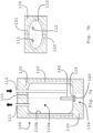
- Fig. 2A and 2B each show a schematic sectional view and a schematic plan view of a small hot water storage tank according to a second exemplary embodiment not according to the invention.
- the small storage tank 100 has a storage tank 110 with a storage volume 110a of ⁇ 20 I and a storage tank wall 110b.
- the storage tank consists of two halves 113, 114, which are fastened to one another at their free ends 113a, 114a. This can be done, for example, by friction welding.
- the storage tank 110 is preferably a plastic storage tank.
- the lower half 114 of the storage tank 110 has an opening 115 for receiving a flange 140.
- the flange 140 can have an electrically operated heating element 142.
- the storage tank also has an outlet 111 and an inlet 112.
- the inlet 112 extends far into the interior of the tank and has a free end 112a.
- Vacuum insulation panels 120, 121, 122 are provided directly on the outside of the wall 110b of the container 110.
- two vacuum insulation panels 121, 122 are provided, which each cover the upper and lower housing halves 113, 114.
- An EPS foam is provided around the vacuum insulation panels 120, 121, 122.
- the foam has an upper end 131, a middle section 132 and a lower section 133 with an opening 134.
- the opening 134 is large enough for the flange to pass through and attach to the opening 115 of the storage tank 110.
- Fig. 3A and 3B each show a schematic sectional view and a schematic plan view of a small hot water storage tank according to a third example not according to the invention.
- the small storage tank 100 according to the third example not according to the invention can essentially correspond to the small storage tank according to the first example not according to the invention and has a storage container 110 with an outlet 111, an inlet 112 and an opening 115 for receiving a heating flange 140.
- At least one vacuum insulation panel 120 can be provided around the container or in particular around the casing of the storage container.
- the vacuum insulation panels 120 consist in cross-section of four different vacuum insulation panels 121 - 124, which are placed around the storage tank 10.
- Fig. 4A and 4B show a schematic sectional view and a schematic plan view of a small hot water storage tank according to a fourth example not according to the invention.
- the small storage tank 100 according to the fourth example essentially corresponds to the small storage tank according to the first example.
- the small storage tank has a vacuum insulation panel 125 which is arranged in the upper area of the small storage tank.
- the remaining structure of the small storage tank according to the fourth example corresponds to the small storage tank according to the first or third example.
- four separate vacuum insulation panels 121 - 124 can be provided around the circumference or the casing of the storage tank.
- the vacuum insulation panel 125 is provided in the upper area or in the area of the lid of the storage tank.
- the vacuum insulation panel serves to thermally insulate the storage tank.
- the EPS foam 130 serves to further improve the insulation of the storage tank.
- Fig. 5A and 5B show a schematic sectional view and a schematic plan view of a small hot water storage tank according to a fifth embodiment not according to the invention.
- the small storage tank according to the fifth example is based on the small storage unit according to the second example not according to the invention.
- the design of the storage container 110 corresponds to the design of the storage container according to the second example. Only the arrangement of the vacuum insulation panels is different in the fifth example than in the second example. While in the second example the vacuum insulation panels are arranged in a circle, according to the fifth example four vacuum insulation panels are provided which are designed straight and surround the storage container 110.
- Fig. 6A and 6B each show a schematic sectional view and a schematic plan view of a small hot water storage tank according to a sixth example not according to the invention.
- the hot water storage tank 100 according to the sixth example preferably has a plastic storage tank 110 with a volume 110a of ⁇ 20 liters, in particular 5 liters, 10 liters or 15 liters.
- the storage tank 110 is designed in two parts or with two halves 113, 114.
- the second half 114 has an opening 115 for receiving a heating flange 140.
- the storage tank 110 has an inlet 112, which preferably extends far into the interior of the storage tank.
- the warm water H within the storage tank 110 will collect in the upper region of the storage tank.
- a vacuum insulation panel 120 is provided in the upper region of the storage tank, which in particular covers part of the upper half of the storage container 110. This is advantageous because it allows improved insulation of the storage container to be provided in a simple and effective manner.
- the storage tank 110 and the vacuum insulation panels 120 can be overmolded with an EPS.
- Fig. 7A and 7B each show a schematic sectional view and a schematic plan view of a small hot water storage tank according to a seventh example not according to the invention.
- the small storage tank 110 according to the seventh example has a storage tank 110 with a volume 110a of ⁇ 20 liters.
- the storage tank has a wall 110b and an opening 115, which is located in the lower area and for receiving a heating flange 140 with an electrically operated heating element 142.
- At least one vacuum insulation panel 120 can be provided around the circumference of the storage tank 110.
- the storage tank 110 is oval in cross section, whereby a reduction in the depth of the small storage tank can be achieved.
- the vacuum insulation panels 120 are provided directly on the outside of the wall 110b of the storage tank.
- the EPS foam 130 is provided or foamed directly on the outside of the vacuum insulation panels 120.
- Fig. 8A and 8B each show a schematic sectional view and a schematic plan view of a small hot water storage tank according to an eighth example not according to the invention.
- the small storage tank 100 according to the eighth example has a storage tank 110.
- the storage tank 110 according to the eighth example can essentially correspond to the storage tank 110 according to the second example not according to the invention.
- the storage tank 110 is provided in two parts with an upper and lower half 113, 114.
- the lower half has an opening 115 for receiving a heating flange with an electrically operated heating element 142.
- At least one vacuum insulation panel is provided around the outer wall of the upper half 113.
- a further vacuum insulation panel 125 is provided in the upper region of the storage tank.
- the vacuum insulation panel is designed in four parts in cross-section, so that four vacuum insulation panels 121 - 124 are provided.
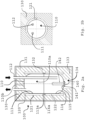
- Fig. 9A and 9B each show a schematic sectional view and a schematic plan view of a small hot water storage tank according to an embodiment of the invention.
- the small storage tank 100 according to the embodiment of the invention has a storage tank 110.
- the storage tank 110 according to the embodiment of the invention can essentially correspond to the storage tank 110 according to the second example not according to the invention.
- the storage tank 110 is provided in two parts with an upper and lower half 113, 114.
- the lower half has an opening 115 for receiving a heating flange with an electrically operated heating element 142.
- At least one vacuum insulation panel is provided around the outer wall of the upper half 113 and the lower half 114, which is connected in the area of the welding zone 113a and 113b by a sealing seam of the barrier film of the vacuum panel.
- Fig.10 shows such a vacuum panel with a sealing seam in the uninstalled state. This panel is wrapped around the container.
Landscapes
- Engineering & Computer Science (AREA)
- Physics & Mathematics (AREA)
- Thermal Sciences (AREA)
- Mechanical Engineering (AREA)
- General Engineering & Computer Science (AREA)
- Chemical & Material Sciences (AREA)
- Combustion & Propulsion (AREA)
- Details Of Fluid Heaters (AREA)
- Heat-Pump Type And Storage Water Heaters (AREA)
Description
- Die vorliegende Erfindung betrifft einen Warmwasser-Kleinspeicher.
- Warmwasser-Kleinspeicher weisen ein Speichervolumen typischerweise von ≤ 20 Ltr. auf. Ein Warmwasser-Kleinspeicher wird zur Warmwasserversorgung eingesetzt.
- Die Druckschrift
JP 2015175530 A - In
JP 2016205648 A - Dokument
DE 102004013623 A1 lehrt einen Warmwasserbereiter, bestehend aus einem Behälteroberteil und einem Behälterunterteil, wobei das Behälterunterteil eine Öffnung aufweist und ein elektrisches Heizelement aufnimmt. - Es ist eine Aufgabe der vorliegenden Erfindung, einen Warmwasser-Kleinspeicher mit geringen Abmessungen vorzusehen.
- Diese Aufgabe wird gelöst durch einen Warmwasser-Kleinspeicher nach Anspruch 1.
- Der Warmwasser-Kleinspeicher weist eine elektrische Heizeinheit zum Erwärmen des sich innerhalb des Speicherbehälters befindlichen Wassers auf. Der Speicherbehälter weist ein Volumen von ≤ 20 Liter. auf. Direkt auf der Außenseite des Speicherbehälters werden Vakuumisolationspaneele vorgesehen. Der Speicherbehälter mit den Vakuumisolationspaneelen wird mittels eines EPS umschäumt. Hierbei wird das EPS direkt auf der Außenseite der Vakuumisolationspaneele vorgesehen.
- Gemäß der vorliegenden Erfindung weist der Speicherbehälter im unteren Bereich eine Öffnung zur Aufnahme eines Flansches mit einem elektrischen Heizkörper auf. Der Bereich um den Flansch ist nicht umschäumt, damit der Flansch auch nachträglich zugänglich ist.
- Gemäß einem weiteren Aspekt der vorliegenden Erfindung befindet sich ein elektrischer Heizkörper innerhalb des Speicherbehälters, ohne dass er herausnehmbar beispielsweise mittels eines Flansches ausgestaltet ist.
- Gemäß der vorliegenden Erfindung ist der Speicherbehälter ein Kunststoffbehälter und die Vakuumisolationspaneele sind direkt auf der Außenseite des Kunststoffbehälters vorgesehen und die EPS-Umschäumung befindet sich direkt an der Außenseite der Vakuumisolationspaneele. Der Kunststoffbehälter kann drucklos ausgestaltet sein.
- Gemäß der vorliegenden Erfindung ist der Kunststoffbehälter zweiteilig ausgestaltet und die beiden Teile des Kunststoffbehälters sind miteinander verschweißt.
- Durch die Verwendung der Vakuumisolationspaneele können die Baumaße des Kleinspeichers reduziert werden. Damit können auch Kleinspeicher mit möglichst geringen Abmessungen vorgesehen werden, sodass ein möglicher Einsatzort dieser Kleinspeicher vergrößert wird.
- Gemäß der vorliegenden Erfindung ist ein Warmwasser-Kleinspeicher vorgesehen, welcher einen Speicherbehälter aufweist, wobei unmittelbar auf dem Speicherbehälter mindestens ein Vakuumisolationspaneel vorgesehen ist, das wiederum durch einen EPS-Schaum unmittelbar umschäumt ist. Durch das Vorsehen des Vakuumisolationspaneels und der EPS-Umschäumung kann eine Reduzierung der Bereitschaftsenergie für den Kleinspeicher erreicht werden. Insbesondere kann im zylindrischen Bereich des Behälters mindestens ein Vakuumisolationspaneel vorgesehen sein.
- Gemäß einem Aspekt der vorliegenden Erfindung ist die Höhe der Vakuumisolationspaneele so ausgestaltet, dass sie den oberen Bereich des Speicherbehälters überragen. Dies führt zu einer weiteren Verbesserung der Isolationseigenschaft und damit zu einer Reduzierung der Bereitschaftsenergie.
- Mit dem erfindungsgemäßen Warmwasser-Kleinspeicher kann eine Reduzierung des Bereitschaftsenergieverbrauchs gleichzeitig mit einer Reduzierung der Gerätemaße ermöglicht werden.
- Durch das Umschäumen des Speicherbehälters und der Vakuumisolationspaneele mit EPS können auch diejenigen Bereiche des Speicherbehälters, welche nicht durch die Vakuumisolationspaneele bedeckt sind, isoliert werden.
- Durch die Umschäumung mit EPS können Abschnitte vorgesehen sein, in welche die Regler oder weitere Komponenten des Kleinspeichers vorgesehen werden können, ohne dabei die Außenmaße des Speicherbehälters zu vergrößern.
- Weitere Ausgestaltungen der Erfindung sind Gegenstand der Unteransprüche.
- Vorteile und Ausführungsbeispiele der Erfindung werden nachstehend unter Bezugnahme auf die Zeichnungen näher erläutert.
- Fig. 1A und 1B
- zeigen eine schematische Schnittansicht und eine schematische Draufsicht auf einen nicht erfindungsgemäßen Warmwasser-Kleinspeicher gemäß einem ersten Beispiel,
- Fig. 2A und 2B
- zeigen jeweils eine schematische Schnittansicht und eine schematische Draufsicht auf einen nicht erfindungsgemäßen Warmwasser-Kleinspeicher gemäß einem zweiten Beispiel,
- Fig. 3A und 3B
- zeigen jeweils eine schematische Schnittansicht und eine schematische Draufsicht auf einen nicht erfindungsgemäßen Warmwasser-Kleinspeicher gemäß einem dritten Beispiel,
- Fig. 4A und 4B
- zeigen jeweils eine schematische Schnittansicht und eine schematische Draufsicht auf einen nicht erfindungsgemäßen Warmwasser-Kleinspeicher gemäß einem vierten Beispiel,
- Fig. 5A und 5B
- zeigen jeweils eine schematische Schnittansicht und eine schematische Draufsicht auf einen nicht erfindungsgemäßen Warmwasser-Kleinspeicher gemäß einem fünften Beispiel,
- Fig. 6A und 6B
- zeigen jeweils eine schematische Schnittansicht und eine schematische Draufsicht auf einen nicht erfindungsgemäßen Warmwasser-Kleinspeicher gemäß einem sechsten Beispiel,
- Fig. 7A und 7B
- zeigen jeweils eine schematische Schnittansicht und eine schematische Draufsicht auf einen nicht erfindungsgemäßen Warmwasser-Kleinspeicher gemäß einem siebten Beispiel, und
- Fig. 8A und 8B
- zeigen jeweils eine schematische Schnittansicht und eine schematische Draufsicht auf einen nicht erfindungsgemäßen Warmwasser-Kleinspeicher gemäß einem achten Beispiel.
- Fig. 9A und 9B
- zeigen jeweils eine schematische Schnittansicht und eine schematische Draufsicht auf einen Warmwasser-Kleinspeicher gemäß der Erfindung.
- und Fig. 10
- zeigt ein einteiliges Vakuumpaneel 120 mit einer Siegelnaht 126 gemäß der Erfindung.
-
Fig. 1A und 1B zeigen eine schematische Schnittansicht und eine schematische Draufsicht auf einen Warmwasser-Kleinspeicher gemäß einem nicht erfindungsgemäßen ersten Beisbeispiel. Der Warmwasser-Kleinspeicher 100 weist einen Speicherbehälter 110 mit einem Speichervolumen von ≤ 20 Ltr. auf. Der Speicherbehälter 110 kann alternativ dazu beispielsweise ein Speichervolumen von 5 Ltr., 10 Ltr. oder 15 Ltr. aufweisen. Andere Volumen sind ebenfalls möglich. - Der Speicherbehälter 100 weist ein Speichervolumen 110a, einen Ablauf 111, einen Zulauf 112 und eine Speicherbehälterwandung 110b auf. An einem Ende (das obere Ende) des Speicherbehälters ist der Ablauf111 vorgesehen. Der Zulauf 112 ragt in das Volumen 110a hinein und weist ein freies Ende 112a auf, welches sich im unteren Bereich des Speicherbehälters 110 befindet. Im unteren Bereich des Speicherbehälters ist ferner eine Öffnung 115 vorgesehen, in welche ein Flansch 140 mit einem elektrisch betreibbaren Heizelement 142 eingeführt werden kann.
- Um die Wandung 110b des Speicherbehälters 110, insbesondere um den zylindrischen Teil der Wandung, ist mindestens ein Vakuumisolationspaneel 120 vorgesehen. Gemäß dem ersten nicht erfindungsgemäßen Beispiel erstreckt sich das Paneel 120 nicht um das obere und untere Ende. Das obere und untere Ende des Speicherbehälters ist damit frei von Vakuumisolationspaneelen. Um den Speicherbehälter 110 und die Vakuumisolationspaneele 120 ist ein EPS umschäumt. Der geschäumte Schaum 130 weist ein oberes Ende 131, einen mittleren Abschnitt 132, ein unteres Ende 133 sowie eine Öffnung 134 auf. Im Bereich des oberen Endes befinden sich der Zulauf 112 und der Ablauf 111. Im Bereich des unteren Endes ist die Öffnung 134 vorgesehen, sodass der Flansch 140 frei von unten zugänglich ist und damit nicht umspritzt ist. Damit kann gewährleistet werden, dass der Flansch und die sich daran befindliche elektrische Heizeinheit 142 demontierbar sind. Wie aus
Fig. 1B hervorgeht, weist der Speicherbehälter einen zylindrischen Mantel auf, welcher durch ein oder zwei Vakuumisolationspaneele 120 umschlossen ist. Die Vakuumisolationspaneele 120 sind unmittelbar auf der Wandung 110b des Behälters platziert. Unmittelbar an der Außenseite der Vakuumisolationspaneele 120 ist die Umschäumung 130 vorgesehen. Die Umschäumung 130 kann eine Recyclingnut 136 an der Vorderseite und eine Recyclingnut 136 an der Rückseite aufweisen. - Beschrieben ist hier einen Speicher, der vorteilhaft unter einem Waschbecken oder einer Küchenspüle montiert wird. Dieser Speicher ist auch zur Montage über einem Waschbecken oder über einer Spüle geeignet, wobei in diesem Anwendungsfall die Wasseranschlüsse vorteilhaft nach unten und der Heizflansch ist dann oben zeigt.
-
Fig. 2A und 2B zeigen jeweils eine schematische Schnittansicht und eine schematische Draufsicht auf einen Warmwasser-Kleinspeicher gemäß einem nicht erfindungsgemäßen zweiten Ausführungsbeispiel. Der Kleinspeicher 100 weist einen Speicherbehälter 110 mit einem Speichervolumen 110a von ≤ 20 I und einer Speicherbehälterwandung 110b auf. Der Speicherbehälter besteht aus zwei Hälften 113, 114, welche an ihren freien Enden 113a, 114a aneinander befestigt werden. Dies kann beispielsweise durch Reibschweißen erfolgen. Der Speicherbehälter 110 ist vorzugsweise ein Kunststoff-Speicherbehälter. Die untere Hälfte 114 des Speicherbehälters 110 weist eine Öffnung 115 zur Aufnahme eines Flansches 140 auf. Der Flansch 140 kann ein elektrisch betreibbares Heizelement 142 aufweisen. Der Speicherbehälter weist ferner einen Ablauf 111 und einen Zulauf 112 auf. Der Zulauf 112 reicht weit in das Innere des Behälters hinein und weist ein freies Ende 112a auf. Unmittelbar an der Außenseite der Wandung 110b des Behälters 110 sind Vakuumisolationspaneele 120, 121, 122 vorgesehen. Insbesondere sind zwei Vakuumisolationspaneele 121, 122 vorgesehen, welche jeweils die obere und untere Gehäusehälfte 113, 114 umgeben. Um die Vakuumisolationspaneele 120, 121, 122 herum ist ein EPS-Schaum vorgesehen. Der Schaum weist ein oberes Ende 131, einen mittleren Abschnitt 132 und einen unteren Abschnitt 133 mit einer Öffnung 134 auf. Die Öffnung 134 ist groß genug, damit der Flansch dort durchgeführt und an der Öffnung 115 des Speicherbehälters 110 befestigt werden kann. -
Fig. 3A und 3B zeigen jeweils eine schematische Schnittansicht und eine schematische Draufsicht auf einen Warmwasser-Kleinspeicher gemäß einem nicht erfindungsgemäßen dritten Beispiel. Der Kleinspeicher 100 gemäß dem nicht erfindungsgemäßen dritten Beispiel kann im Wesentlichen dem Kleinspeicher gemäß dem nicht erfindungsgemäßen ersten Beispiel entsprechen und weist einen Speicherbehälter 110 mit einem Ablauf 111, einem Zulauf 112 und einer Öffnung 115 zur Aufnahme eines Heizflansches 140 auf. Um den Behälter herum bzw. insbesondere um den Mantel des Speicherbehälters herum kann mindestens ein Vakuumisolationspaneel 120 vorgesehen sein. - Wie aus
Fig. 3B zu sehen, bestehen die Vakuumisolationspaneele 120 im Querschnitt aus vier verschiedenen Vakuumisolationspaneelen 121 - 124, welche um den Speicherbehälter 10 herum platziert sind. -
Fig. 4A und 4B zeigen jeweils eine schematische Schnittansicht und eine schematische Draufsicht auf einen Warmwasser-Kleinspeicher gemäß einem vierten nicht erfindungsgemäßen Beispiel. Der Kleinspeicher 100 gemäß dem vierten Beispiel entspricht im Wesentlichen dem Kleinspeicher gemäß dem ersten Beispiel. Zusätzlich dazu weist der Kleinspeicher ein Vakuumisolationspaneel 125 auf, welches im oberen Bereich des Kleinspeichers angeordnet ist. Der restliche Aufbau des Kleinspeichers gemäß dem vierten Beispiel entspricht dabei dem Kleinspeicher gemäß dem ersten oder dem dritten Beispiel. Wie inFig. 4B zu sehen, können vier separate Vakuumisolationspaneele 121 - 124 um den Umfang bzw. den Mantel des Speicherbehälters herum vorgesehen sein. Das Vakuumisolationspaneel 125 ist im oberen Bereich bzw. im Bereich des Deckels des Speicherbehälters vorgesehen. Das Vakuumisolationspaneel dient der thermischen Isolierung des Speichers. Die EPS-Umschäumung 130 dient der weiteren Verbesserung der Isolation des Speicherbehälters. -
Fig. 5A und 5B zeigen jeweils eine schematische Schnittansicht und eine schematische Draufsicht auf einen Warmwasser-Kleinspeicher gemäß einem nicht erfindungsgemäßen fünften Ausführungsbeispiel. Der Kleinspeicher gemäß dem fünften Beispiel basiert auf dem Kleinspeicher gemäß dem nicht erfindungsgemäßen zweiten Beispiel. Die Ausgestaltung des Speicherbehälters 110 entspricht dabei der Ausgestaltung des Speicherbehälters gemäß dem zweiten Beispiel. Lediglich die Anordnung der Vakuumisolationspaneele ist im fünften Beispiel anders als im zweiten Beispiel. Während im zweiten Beispiel die Vakuumisolationspaneele kreisförmig angeordnet sind, sind gemäß dem fünften Beispiel vier Vakuumisolationspaneele vorgesehen, welche gerade ausgestaltet sind und den Speicherbehälter 110 umgeben. -
Fig. 6A und 6B zeigen jeweils eine schematische Schnittansicht und eine schematische Draufsicht auf einen Warmwasser-Kleinspeicher gemäß einem nicht erfindungsgemäßen sechsten Beispiel. Der Warmwasser-Speicher 100 gemäß dem sechsten Beispiel weist vorzugsweise einen Kunststoff-Speicherbehälter 110 mit einem Volumen 110a von ≤ 20 Ltr., insbesondere 5 Ltr., 10 Ltr. oder 15 Ltr. auf. Der Speicherbehälter 110 ist zweiteilig bzw. mit zwei Hälften 113, 114 ausgeführt. Die zweite Hälfte 114 weist eine Öffnung 115 zur Aufnahme eines Heizflansches 140 auf. Der Speicherbehälter 110 weist einen Zulauf 112 auf, welcher vorzugsweise weit in das Innere des Speicherbehälters hineinragt. Das warme Wasser H innerhalb des Speicherbehälters 110 wird sich im oberen Bereich des Speicherbehälters ansammeln. Gemäß dem sechsten Beispiel ist im oberen Bereich des Speichers ein Vakuumisolationspaneel 120 vorgesehen, welches insbesondere einen Teil der oberen Hälfte des Speicherbehälters 110 abdeckt. Dies ist vorteilhaft, weil somit auf einfache und effektive Art und Weise eine verbesserte Isolierung des Speicherbehälters vorgesehen sein kann. - Der Speicherbehälter 110 und die Vakuumisolationspaneele 120 können durch ein EPS umspritzt sein.
-
Fig. 7A und 7B zeigen jeweils eine schematische Schnittansicht und eine schematische Draufsicht auf einen Warmwasser-Kleinspeicher gemäß einem nicht erfindungsgemäßen siebten Beispiel. Der Kleinspeicher 110 gemäß dem siebten Beispiel weist einen Speicherbehälter 110 mit einem Volumen 110a von ≤ 20 Ltr. auf. Der Speicherbehälter weist eine Wandung 110b sowie eine Öffnung 115 auf, welche sich im unteren Bereich befindet und zur Aufnahme eines Heizflansches 140 mit einem elektrisch betreibbaren Heizelement 142 auf. Um den Umfang des Speicherbehälters 110 herum kann mindestens ein Vakuumisolationspaneel 120 vorgesehen sein. Gemäß dem siebten Beispiel ist der Speicherbehälter 110 im Querschnitt oval ausgestaltet, wodurch eine Verringerung der Tiefe des Kleinspeichers erreicht werden kann. Die Vakuumisolationspaneele 120 sind unmittelbar auf der Außenseite der Wandung 110b des Speicherbehälters vorgesehen. Der EPS-Schaum 130 wird unmittelbar an der Außenseite der Vakuumisolationspaneele 120 vorgesehen bzw. geschäumt. -
Fig. 8A und 8B zeigen jeweils eine schematische Schnittansicht und eine schematische Draufsicht auf einen Warmwasser-Kleinspeicher gemäß einem nicht erfindungsgemäßen achten Beispiel. Der Kleinspeicher 100 gemäß dem achten Beispiel weist einen Speicherbehälter 110 auf. Der Speicherbehälter 110 gemäß dem achten Beispiel kann dem Speicherbehälter 110 gemäß dem nicht erfindungsgemäßen zweiten Beispiel im Wesentlichen entsprechen. Der Speicherbehälter 110 ist zweiteilig mit einer oberen und unteren Hälfte 113, 114 vorgesehen. Die untere Hälfte weist eine Öffnung 115 zur Aufnahme eines Heizflansches mit einem elektrisch betreibbaren Heizelement 142 auf. Um die äußere Wandung der oberen Hälfte 113 ist mindestens ein Vakuumisolationspaneel vorgesehen. Ein weiteres Vakuumisolationspaneel 125 ist im oberen Bereich des Speicherbehälters vorgesehen. Wie ausFig. 8 hervorgeht, ist das Vakuumisolationspaneel im Querschnitt vierteilig ausgestaltet, sodass vier Vakuumisolationspaneele 121 - 124 vorgesehen sind. -
Fig. 9A und 9B zeigen jeweils eine schematische Schnittansicht und eine schematische Draufsicht auf einen Warmwasser-Kleinspeicher gemäß einem erfindungsgemäßen Ausführungsbeispiel. Der Kleinspeicher 100 gemäß dem erfindungsgemäßen Ausführungsbeispiel weist einen Speicherbehälter 110 auf. Der Speicherbehälter 110 gemäß dem erfindungsgemäßen Ausführungsbeispiel kann dem Speicherbehälter 110 gemäß dem nicht erfindungsgemäßen zweiten Beispiel im Wesentlichen entsprechen. Der Speicherbehälter 110 ist zweiteilig mit einer oberen und unteren Hälfte 113, 114 vorgesehen. Die untere Hälfte weist eine Öffnung 115 zur Aufnahme eines Heizflansches mit einem elektrisch betreibbaren Heizelement 142 auf. Um die äußere Wandung der oberen Hälfte 113 und der unteren Hälfte 114 ist mindestens ein Vakuumisolationspaneel vorgesehen, dass im Bereich der Schweißzone 113a und 113b durch eine Siegelnaht der Barrierefolie des Vakumpaneel verbunden ist. -
Fig. 10 zeigt ein solches Vakuumpaneel mit einer Siegelnaht im unverbauten Zustand. Dieses Paneel wird um den Behälter gewickelt.
Claims (2)
- Warmwasser-Kleinspeicher (100) miteinem Speicherbehälter (110) mit einem Volumen (110a) von ≤ 20 Ltr.,einem elektrisch betreibbaren Heizelement (142),wobei der Speicherbehälter (110) als Kunststoffbehälter ausgestaltet ist und ein oberes und ein unteres Teil (113, 114) aufweist,wobei der untere Teil (114) des Speicherbehälters (110) eine Öffnung (115) aufweist undwobei ein Heizflansch (140) mit dem elektrisch betreibbaren Heizelement (142) durch die Öffnung (115) eingeführt wird, sodass der Heizflansch (140) in das Speichervolumen (110a) hineinragt und das elektrisch beheizbare Heizelement (142) das sich in dem Speichervolumen (110a) befindliche Wasser erwärmt,dadurch gekennzeichnet, dassmindestens ein Vakuumisolationspaneel (120) direkt auf dem Speicherbehälter (110) um die äußere Wandung der oberen Hälfte (113) und der unteren Hälfte (114) und eine EPS-Umschäumung (130) direkt an der Außenseite des mindestens einen Vakuumisolationspaneels (120) vorgesehen ist, wobei die EPS-Umschäumung (130) die komplette Außenseite des mindestens einen Vakuumisolationspaneels (120) umgibt,wobei das obere und das untere Teil des Speicherbehälters (110) miteinander entlang einer Schweißzone (113a, 114a) verschweißt sind,wobei das mindestens eine Vakuumisolationspaneel (120) zwei Abschnitte mit einer Siegelnaht (126) dazwischen aufweist, wobei die Siegelnaht (126) die Schweißzone (113a, 114a) im montierten Zustand abdeckt.
- Warmwasser-Kleinspeicher nach Anspruch 1,
dadurch gekennzeichnet,
dass der Speicherbehälter (110) als druckloser Kunststoffbehälter ausgestaltet ist.
Applications Claiming Priority (1)
| Application Number | Priority Date | Filing Date | Title |
|---|---|---|---|
| DE102019001629.7A DE102019001629A1 (de) | 2019-03-08 | 2019-03-08 | Warmwasser-Kleinspeicher |
Publications (2)
| Publication Number | Publication Date |
|---|---|
| EP3705805A1 EP3705805A1 (de) | 2020-09-09 |
| EP3705805B1 true EP3705805B1 (de) | 2024-09-18 |
Family
ID=69780033
Family Applications (1)
| Application Number | Title | Priority Date | Filing Date |
|---|---|---|---|
| EP20161508.5A Active EP3705805B1 (de) | 2019-03-08 | 2020-03-06 | Warmwasser-kleinspeicher |
Country Status (3)
| Country | Link |
|---|---|
| EP (1) | EP3705805B1 (de) |
| DE (1) | DE102019001629A1 (de) |
| PT (1) | PT3705805T (de) |
Families Citing this family (1)
| Publication number | Priority date | Publication date | Assignee | Title |
|---|---|---|---|---|
| US20240263835A1 (en) * | 2023-02-08 | 2024-08-08 | Rheem Manufacturing Company | Systems and Methods for Vacuum Insulation Panels for Water Heater Tanks |
Family Cites Families (8)
| Publication number | Priority date | Publication date | Assignee | Title |
|---|---|---|---|---|
| DE29811678U1 (de) * | 1998-07-01 | 1998-08-27 | Stiebel Eltron Gmbh & Co Kg, 37603 Holzminden | Warmwasserspeicher |
| FR2803652B1 (fr) * | 2000-01-12 | 2002-06-14 | Electricite De France | Chauffe-eau electrique a forte isolation thermique |
| DE20109029U1 (de) * | 2001-05-30 | 2002-10-10 | Electrolux Haustechnik GmbH, 90449 Nürnberg | Speicherbehälter eines Warmwasserbereiters |
| DE102004013623A1 (de) * | 2004-03-19 | 2005-10-06 | BSH Bosch und Siemens Hausgeräte GmbH | Flüssigkeitswärmebehälter eines Haushaltsgerätes, insbesondere eines Warmwasserbereiters |
| EP2700886A3 (de) * | 2012-08-23 | 2016-09-07 | Vaillant GmbH | Warmwasserspeicher |
| JP6206265B2 (ja) * | 2014-03-13 | 2017-10-04 | 三菱電機株式会社 | 貯湯式給湯機 |
| JP6332123B2 (ja) * | 2015-04-16 | 2018-05-30 | 三菱電機株式会社 | 貯湯式給湯機 |
| PL3315872T3 (pl) * | 2016-10-27 | 2021-09-20 | Stiebel Eltron Gmbh & Co. Kg | Zasobnik ciepłej wody i kołnierz grzewczy dla zasobnika ciepłej wody |
-
2019
- 2019-03-08 DE DE102019001629.7A patent/DE102019001629A1/de active Pending
-
2020
- 2020-03-06 PT PT201615085T patent/PT3705805T/pt unknown
- 2020-03-06 EP EP20161508.5A patent/EP3705805B1/de active Active
Also Published As
| Publication number | Publication date |
|---|---|
| DE102019001629A1 (de) | 2020-09-10 |
| EP3705805A1 (de) | 2020-09-09 |
| PT3705805T (pt) | 2024-12-16 |
Similar Documents
| Publication | Publication Date | Title |
|---|---|---|
| EP3457027B1 (de) | Dampferzeuger für ein dampfgargerät, dampfgargerät mit einem solchen dampferzeuger und verfahren zur dampferzeugung | |
| EP2458298A2 (de) | Elektrischer Wassererwärmer | |
| DE102021118041A1 (de) | Haustechnikgerät | |
| EP3705805A1 (de) | Warmwasser-kleinspeicher | |
| EP3315872B1 (de) | Warmwasserspeicher und heizflansch für einen warmwasserspeicher | |
| DE69033326T2 (de) | Anschluss eines Rohrheizkörpers mit einer Zwischenhülse | |
| DE3937204A1 (de) | Konverter fuer planarantennen | |
| DE19722635C2 (de) | Innenbehälter für einen Heißwasserspeicher | |
| DE4403638C2 (de) | Gerät zum Erhitzen von Flüssigkeiten | |
| DE102011054687A1 (de) | Gargerät und Verfahren zum Betreiben eines Gargerätes | |
| EP3279570A1 (de) | Verdampfereinrichtung für wasser und dampfgarer mit einer solchen verdampfereinrichtung | |
| EP3771366A1 (de) | Topfbodenheizungsanordnung für eine küchenmaschine | |
| DE10296689T5 (de) | Elektrolytkondensator und Verfahren zur dessen Kühlung | |
| EP1571404A1 (de) | Schichtenspeicher mit einem Gehäuse und einer Isolierung | |
| EP0334997B1 (de) | Sonnenkollektor | |
| DE3337900A1 (de) | Temperaturfuehler | |
| DE102013106849A1 (de) | Gargerät | |
| DE102015102981A1 (de) | Frontblech für ein Gargerät, Baugruppe mit einem Frontblech und einem Gargeräte-Innenkasten sowie Verfahren zur Herstellung der Baugruppe | |
| DE102017114616B4 (de) | Wärmeisolierung für Warmwasserspeicher | |
| DE102021118039A1 (de) | Haustechnikgerät und elektrischer Schaltkasten für ein Haustechnikgerät | |
| DE102008056620B3 (de) | Verbindungsschacht | |
| EP1850712B1 (de) | Elektrischer wasserkocher | |
| DE9101953U1 (de) | Brauchwasserspeicher | |
| EP0282916B1 (de) | Brauchwasserspeicher | |
| DE102024115760A1 (de) | Vorrichtung zur Dampferzeugung und wasserführendes Haushaltsgerät mit einer solchen Vorrichtung |
Legal Events
| Date | Code | Title | Description |
|---|---|---|---|
| PUAI | Public reference made under article 153(3) epc to a published international application that has entered the european phase |
Free format text: ORIGINAL CODE: 0009012 |
|
| STAA | Information on the status of an ep patent application or granted ep patent |
Free format text: STATUS: THE APPLICATION HAS BEEN PUBLISHED |
|
| AK | Designated contracting states |
Kind code of ref document: A1 Designated state(s): AL AT BE BG CH CY CZ DE DK EE ES FI FR GB GR HR HU IE IS IT LI LT LU LV MC MK MT NL NO PL PT RO RS SE SI SK SM TR |
|
| AX | Request for extension of the european patent |
Extension state: BA ME |
|
| STAA | Information on the status of an ep patent application or granted ep patent |
Free format text: STATUS: REQUEST FOR EXAMINATION WAS MADE |
|
| 17P | Request for examination filed |
Effective date: 20210309 |
|
| RBV | Designated contracting states (corrected) |
Designated state(s): AL AT BE BG CH CY CZ DE DK EE ES FI FR GB GR HR HU IE IS IT LI LT LU LV MC MK MT NL NO PL PT RO RS SE SI SK SM TR |
|
| STAA | Information on the status of an ep patent application or granted ep patent |
Free format text: STATUS: EXAMINATION IS IN PROGRESS |
|
| 17Q | First examination report despatched |
Effective date: 20221130 |
|
| P01 | Opt-out of the competence of the unified patent court (upc) registered |
Effective date: 20230524 |
|
| GRAP | Despatch of communication of intention to grant a patent |
Free format text: ORIGINAL CODE: EPIDOSNIGR1 |
|
| STAA | Information on the status of an ep patent application or granted ep patent |
Free format text: STATUS: GRANT OF PATENT IS INTENDED |
|
| INTG | Intention to grant announced |
Effective date: 20240416 |
|
| GRAS | Grant fee paid |
Free format text: ORIGINAL CODE: EPIDOSNIGR3 |
|
| GRAA | (expected) grant |
Free format text: ORIGINAL CODE: 0009210 |
|
| STAA | Information on the status of an ep patent application or granted ep patent |
Free format text: STATUS: THE PATENT HAS BEEN GRANTED |
|
| AK | Designated contracting states |
Kind code of ref document: B1 Designated state(s): AL AT BE BG CH CY CZ DE DK EE ES FI FR GB GR HR HU IE IS IT LI LT LU LV MC MK MT NL NO PL PT RO RS SE SI SK SM TR |
|
| REG | Reference to a national code |
Ref country code: GB Ref legal event code: FG4D Free format text: NOT ENGLISH |
|
| REG | Reference to a national code |
Ref country code: CH Ref legal event code: EP |
|
| REG | Reference to a national code |
Ref country code: DE Ref legal event code: R096 Ref document number: 502020009242 Country of ref document: DE |
|
| REG | Reference to a national code |
Ref country code: IE Ref legal event code: FG4D Free format text: LANGUAGE OF EP DOCUMENT: GERMAN |
|
| REG | Reference to a national code |
Ref country code: PT Ref legal event code: SC4A Ref document number: 3705805 Country of ref document: PT Date of ref document: 20241216 Kind code of ref document: T Free format text: AVAILABILITY OF NATIONAL TRANSLATION Effective date: 20241210 |
|
| REG | Reference to a national code |
Ref country code: LT Ref legal event code: MG9D |
|
| PG25 | Lapsed in a contracting state [announced via postgrant information from national office to epo] |
Ref country code: NO Free format text: LAPSE BECAUSE OF FAILURE TO SUBMIT A TRANSLATION OF THE DESCRIPTION OR TO PAY THE FEE WITHIN THE PRESCRIBED TIME-LIMIT Effective date: 20241218 |
|
| PG25 | Lapsed in a contracting state [announced via postgrant information from national office to epo] |
Ref country code: GR Free format text: LAPSE BECAUSE OF FAILURE TO SUBMIT A TRANSLATION OF THE DESCRIPTION OR TO PAY THE FEE WITHIN THE PRESCRIBED TIME-LIMIT Effective date: 20241219 Ref country code: FI Free format text: LAPSE BECAUSE OF FAILURE TO SUBMIT A TRANSLATION OF THE DESCRIPTION OR TO PAY THE FEE WITHIN THE PRESCRIBED TIME-LIMIT Effective date: 20240918 |
|
| PG25 | Lapsed in a contracting state [announced via postgrant information from national office to epo] |
Ref country code: BG Free format text: LAPSE BECAUSE OF FAILURE TO SUBMIT A TRANSLATION OF THE DESCRIPTION OR TO PAY THE FEE WITHIN THE PRESCRIBED TIME-LIMIT Effective date: 20240918 |
|
| PG25 | Lapsed in a contracting state [announced via postgrant information from national office to epo] |
Ref country code: LV Free format text: LAPSE BECAUSE OF FAILURE TO SUBMIT A TRANSLATION OF THE DESCRIPTION OR TO PAY THE FEE WITHIN THE PRESCRIBED TIME-LIMIT Effective date: 20240918 |
|
| PG25 | Lapsed in a contracting state [announced via postgrant information from national office to epo] |
Ref country code: HR Free format text: LAPSE BECAUSE OF FAILURE TO SUBMIT A TRANSLATION OF THE DESCRIPTION OR TO PAY THE FEE WITHIN THE PRESCRIBED TIME-LIMIT Effective date: 20240918 |
|
| REG | Reference to a national code |
Ref country code: NL Ref legal event code: MP Effective date: 20240918 |
|
| PG25 | Lapsed in a contracting state [announced via postgrant information from national office to epo] |
Ref country code: RS Free format text: LAPSE BECAUSE OF FAILURE TO SUBMIT A TRANSLATION OF THE DESCRIPTION OR TO PAY THE FEE WITHIN THE PRESCRIBED TIME-LIMIT Effective date: 20241218 |
|
| PG25 | Lapsed in a contracting state [announced via postgrant information from national office to epo] |
Ref country code: RS Free format text: LAPSE BECAUSE OF FAILURE TO SUBMIT A TRANSLATION OF THE DESCRIPTION OR TO PAY THE FEE WITHIN THE PRESCRIBED TIME-LIMIT Effective date: 20241218 Ref country code: NO Free format text: LAPSE BECAUSE OF FAILURE TO SUBMIT A TRANSLATION OF THE DESCRIPTION OR TO PAY THE FEE WITHIN THE PRESCRIBED TIME-LIMIT Effective date: 20241218 Ref country code: LV Free format text: LAPSE BECAUSE OF FAILURE TO SUBMIT A TRANSLATION OF THE DESCRIPTION OR TO PAY THE FEE WITHIN THE PRESCRIBED TIME-LIMIT Effective date: 20240918 Ref country code: HR Free format text: LAPSE BECAUSE OF FAILURE TO SUBMIT A TRANSLATION OF THE DESCRIPTION OR TO PAY THE FEE WITHIN THE PRESCRIBED TIME-LIMIT Effective date: 20240918 Ref country code: GR Free format text: LAPSE BECAUSE OF FAILURE TO SUBMIT A TRANSLATION OF THE DESCRIPTION OR TO PAY THE FEE WITHIN THE PRESCRIBED TIME-LIMIT Effective date: 20241219 Ref country code: FI Free format text: LAPSE BECAUSE OF FAILURE TO SUBMIT A TRANSLATION OF THE DESCRIPTION OR TO PAY THE FEE WITHIN THE PRESCRIBED TIME-LIMIT Effective date: 20240918 Ref country code: BG Free format text: LAPSE BECAUSE OF FAILURE TO SUBMIT A TRANSLATION OF THE DESCRIPTION OR TO PAY THE FEE WITHIN THE PRESCRIBED TIME-LIMIT Effective date: 20240918 |
|
| PG25 | Lapsed in a contracting state [announced via postgrant information from national office to epo] |
Ref country code: NL Free format text: LAPSE BECAUSE OF FAILURE TO SUBMIT A TRANSLATION OF THE DESCRIPTION OR TO PAY THE FEE WITHIN THE PRESCRIBED TIME-LIMIT Effective date: 20240918 |
|
| PG25 | Lapsed in a contracting state [announced via postgrant information from national office to epo] |
Ref country code: IS Free format text: LAPSE BECAUSE OF FAILURE TO SUBMIT A TRANSLATION OF THE DESCRIPTION OR TO PAY THE FEE WITHIN THE PRESCRIBED TIME-LIMIT Effective date: 20250118 |
|
| PG25 | Lapsed in a contracting state [announced via postgrant information from national office to epo] |
Ref country code: RO Free format text: LAPSE BECAUSE OF FAILURE TO SUBMIT A TRANSLATION OF THE DESCRIPTION OR TO PAY THE FEE WITHIN THE PRESCRIBED TIME-LIMIT Effective date: 20240918 Ref country code: SM Free format text: LAPSE BECAUSE OF FAILURE TO SUBMIT A TRANSLATION OF THE DESCRIPTION OR TO PAY THE FEE WITHIN THE PRESCRIBED TIME-LIMIT Effective date: 20240918 |
|
| PG25 | Lapsed in a contracting state [announced via postgrant information from national office to epo] |
Ref country code: ES Free format text: LAPSE BECAUSE OF FAILURE TO SUBMIT A TRANSLATION OF THE DESCRIPTION OR TO PAY THE FEE WITHIN THE PRESCRIBED TIME-LIMIT Effective date: 20240918 |
|
| PG25 | Lapsed in a contracting state [announced via postgrant information from national office to epo] |
Ref country code: EE Free format text: LAPSE BECAUSE OF FAILURE TO SUBMIT A TRANSLATION OF THE DESCRIPTION OR TO PAY THE FEE WITHIN THE PRESCRIBED TIME-LIMIT Effective date: 20240918 |
|
| PG25 | Lapsed in a contracting state [announced via postgrant information from national office to epo] |
Ref country code: PL Free format text: LAPSE BECAUSE OF FAILURE TO SUBMIT A TRANSLATION OF THE DESCRIPTION OR TO PAY THE FEE WITHIN THE PRESCRIBED TIME-LIMIT Effective date: 20240918 Ref country code: CZ Free format text: LAPSE BECAUSE OF FAILURE TO SUBMIT A TRANSLATION OF THE DESCRIPTION OR TO PAY THE FEE WITHIN THE PRESCRIBED TIME-LIMIT Effective date: 20240918 |
|
| PG25 | Lapsed in a contracting state [announced via postgrant information from national office to epo] |
Ref country code: IT Free format text: LAPSE BECAUSE OF FAILURE TO SUBMIT A TRANSLATION OF THE DESCRIPTION OR TO PAY THE FEE WITHIN THE PRESCRIBED TIME-LIMIT Effective date: 20240918 Ref country code: SK Free format text: LAPSE BECAUSE OF FAILURE TO SUBMIT A TRANSLATION OF THE DESCRIPTION OR TO PAY THE FEE WITHIN THE PRESCRIBED TIME-LIMIT Effective date: 20240918 |
|
| REG | Reference to a national code |
Ref country code: DE Ref legal event code: R097 Ref document number: 502020009242 Country of ref document: DE |
|
| PG25 | Lapsed in a contracting state [announced via postgrant information from national office to epo] |
Ref country code: DK Free format text: LAPSE BECAUSE OF FAILURE TO SUBMIT A TRANSLATION OF THE DESCRIPTION OR TO PAY THE FEE WITHIN THE PRESCRIBED TIME-LIMIT Effective date: 20240918 |
|
| PLBE | No opposition filed within time limit |
Free format text: ORIGINAL CODE: 0009261 |
|
| STAA | Information on the status of an ep patent application or granted ep patent |
Free format text: STATUS: NO OPPOSITION FILED WITHIN TIME LIMIT |
|
| 26N | No opposition filed |
Effective date: 20250619 |
|
| PG25 | Lapsed in a contracting state [announced via postgrant information from national office to epo] |
Ref country code: SE Free format text: LAPSE BECAUSE OF FAILURE TO SUBMIT A TRANSLATION OF THE DESCRIPTION OR TO PAY THE FEE WITHIN THE PRESCRIBED TIME-LIMIT Effective date: 20240918 |
|
| PG25 | Lapsed in a contracting state [announced via postgrant information from national office to epo] |
Ref country code: MC Free format text: LAPSE BECAUSE OF FAILURE TO SUBMIT A TRANSLATION OF THE DESCRIPTION OR TO PAY THE FEE WITHIN THE PRESCRIBED TIME-LIMIT Effective date: 20240918 |
|
| REG | Reference to a national code |
Ref country code: CH Ref legal event code: H13 Free format text: ST27 STATUS EVENT CODE: U-0-0-H10-H13 (AS PROVIDED BY THE NATIONAL OFFICE) Effective date: 20251023 |
|
| PG25 | Lapsed in a contracting state [announced via postgrant information from national office to epo] |
Ref country code: LU Free format text: LAPSE BECAUSE OF NON-PAYMENT OF DUE FEES Effective date: 20250306 |
|
| GBPC | Gb: european patent ceased through non-payment of renewal fee |
Effective date: 20250306 |
|
| REG | Reference to a national code |
Ref country code: BE Ref legal event code: MM Effective date: 20250331 |
|
| PG25 | Lapsed in a contracting state [announced via postgrant information from national office to epo] |
Ref country code: GB Free format text: LAPSE BECAUSE OF NON-PAYMENT OF DUE FEES Effective date: 20250306 |
|
| PG25 | Lapsed in a contracting state [announced via postgrant information from national office to epo] |
Ref country code: FR Free format text: LAPSE BECAUSE OF NON-PAYMENT OF DUE FEES Effective date: 20250331 |
|
| PG25 | Lapsed in a contracting state [announced via postgrant information from national office to epo] |
Ref country code: BE Free format text: LAPSE BECAUSE OF NON-PAYMENT OF DUE FEES Effective date: 20250331 |
|
| PG25 | Lapsed in a contracting state [announced via postgrant information from national office to epo] |
Ref country code: CH Free format text: LAPSE BECAUSE OF NON-PAYMENT OF DUE FEES Effective date: 20250331 |
|
| PG25 | Lapsed in a contracting state [announced via postgrant information from national office to epo] |
Ref country code: IE Free format text: LAPSE BECAUSE OF NON-PAYMENT OF DUE FEES Effective date: 20250306 |
|
| PGFP | Annual fee paid to national office [announced via postgrant information from national office to epo] |
Ref country code: DE Payment date: 20260319 Year of fee payment: 7 |
|
| PGFP | Annual fee paid to national office [announced via postgrant information from national office to epo] |
Ref country code: PT Payment date: 20260226 Year of fee payment: 7 |