EP3705739A1 - Schutzkappe für gewindebolzen - Google Patents
Schutzkappe für gewindebolzen Download PDFInfo
- Publication number
- EP3705739A1 EP3705739A1 EP20159681.4A EP20159681A EP3705739A1 EP 3705739 A1 EP3705739 A1 EP 3705739A1 EP 20159681 A EP20159681 A EP 20159681A EP 3705739 A1 EP3705739 A1 EP 3705739A1
- Authority
- EP
- European Patent Office
- Prior art keywords
- protective cap
- cap
- head
- protective
- cap according
- Prior art date
- Legal status (The legal status is an assumption and is not a legal conclusion. Google has not performed a legal analysis and makes no representation as to the accuracy of the status listed.)
- Granted
Links
Images
Classifications
-
- F—MECHANICAL ENGINEERING; LIGHTING; HEATING; WEAPONS; BLASTING
- F16—ENGINEERING ELEMENTS AND UNITS; GENERAL MEASURES FOR PRODUCING AND MAINTAINING EFFECTIVE FUNCTIONING OF MACHINES OR INSTALLATIONS; THERMAL INSULATION IN GENERAL
- F16B—DEVICES FOR FASTENING OR SECURING CONSTRUCTIONAL ELEMENTS OR MACHINE PARTS TOGETHER, e.g. NAILS, BOLTS, CIRCLIPS, CLAMPS, CLIPS OR WEDGES; JOINTS OR JOINTING
- F16B37/00—Nuts or like thread-engaging members
- F16B37/14—Cap nuts; Nut caps or bolt caps
-
- F—MECHANICAL ENGINEERING; LIGHTING; HEATING; WEAPONS; BLASTING
- F16—ENGINEERING ELEMENTS AND UNITS; GENERAL MEASURES FOR PRODUCING AND MAINTAINING EFFECTIVE FUNCTIONING OF MACHINES OR INSTALLATIONS; THERMAL INSULATION IN GENERAL
- F16B—DEVICES FOR FASTENING OR SECURING CONSTRUCTIONAL ELEMENTS OR MACHINE PARTS TOGETHER, e.g. NAILS, BOLTS, CIRCLIPS, CLAMPS, CLIPS OR WEDGES; JOINTS OR JOINTING
- F16B33/00—Features common to bolt and nut
- F16B33/004—Sealing; Insulation
Definitions
- the invention relates to a protective cap for threaded bolts consisting of a cap head and a cap shell, on which a sealing lip is formed on its end facing away from the cap head.
- Protective caps for screw connections are known in many ways. In particular, they serve to protect the covered screw connections from corrosion. The purpose of the caps is to prevent moisture from reaching the screw connections and damaging the screw connections.
- the protective caps are usually made of plastic. Such a protective cap is, for example DE 10 2005 030 817 A1 known.
- the known protective caps fulfill the tasks assigned to them.
- applications are known in which the known protective caps can only partially prevent damage to the screw connection by moisture. This is particularly the case in assembly situations in which the protective cap is attached to the side of a component facing the floor, so-called “upside-down assembly".
- Such installation situations can lead to an accumulation of liquid in the protective cap. On the one hand, this can result from the fact that the component on which the protective cap rests has a rough surface and therefore cannot be adequately sealed.
- strong temperature fluctuations can cause condensation to form in the cap, which then collects in the head of the cap due to gravity. Such water, but also other liquids which have penetrated the protective cap, can damage the screw bolts.
- the invention aims to remedy this.
- the invention is based on the object of creating a protective cap in which liquids which have penetrated into the protective cap or which have formed in the protective cap can be discharged.
- this object is achieved in that a plug is provided on the cap head, in which at least one opening is formed.
- a protective cap is created in which a discharge of liquid that has penetrated into the protective cap or formed in the protective cap is possible. Through the opening there is the possibility that liquid located in the protective cap can escape from the protective cap due to gravity in the case of an upside-down installation. Consequently, there is no risk of the liquid collecting in the protective cap and thereby damaging the screw connection covered by the protective cap.
- the openings are formed by slots.
- this design ensures that the liquid escapes reliably from the protective cap; on the other hand, the openings can be narrow, so that the risk of dirt or the like entering through the openings into the protective cap is low.
- the slots are advantageously aligned at right angles to one another and cross one another. This way of arranging the openings ensures that the openings extend over a large area of the cap head, so that liquid located in the protective cap can also be discharged from the edge area of the stopper.
- the stopper is formed by a disk onto which a pipe section is formed, on whose side facing away from the disk a ring is formed.
- the disk lies in a recess in the cap head. This enables the stopper to be arranged flush in the cap head, so that the stopper has no disadvantages for the use of the protective cap in comparison with known protective caps.
- the stopper is held clamped in the cap head. This design makes it very easy to assemble the plug. At the same time, this offers the possibility of replacing the stopper if necessary.
- the cap head is preferably provided with a screwing aid on the outside at its end.
- the screwing aid simplifies handling both during assembly and when removing the protective cap.
- the screwing aid is extremely preferably formed by an external polygon.
- the configuration in the form of an external polygon enables, on the one hand, simple screwing with the aid of known tools.
- the design as an external polygon leads to greater stability in the area of the cap head. The risk of damage is reduced by providing the polygon.
- axial webs are provided on the inside which are radially aligned and that the clear width between opposing webs essentially corresponds to the diameter of the threaded bolt.
- the webs provided on the inside of the cap make it possible to screw the protective cap onto the thread of the threaded bolt.
- the distance between the webs, which is matched to the respective diameter of the threaded bolts, enables the thread to be cut into the free ends of the webs. It is therefore not necessary to introduce a thread into the webs during the manufacture of the protective cap; rather, this takes place in a self-tapping manner when the cap is screwed onto the respective threaded bolt.
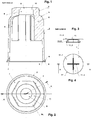
- the protective cap chosen as an exemplary embodiment is intended in particular for use in threaded bolts in which the assembly takes place on the side of a component facing the floor, so-called "head-over-assembly". It consists of a cap head 1 and a cap shell 2. At the end of the cap facing away from the cap head 1 and facing the respective component, a settling lip 3 and a sealing lip 4 are formed. In the assembled state of the protective cap, the sealing lip 4 rests on the respective component.
- the settling lip 3 likewise protrudes onto the component.
- the channel 5 provided between the settling lip 3 and the sealing lip 4 can be seen as an interruption between the two lips 3 and 4.
- the channel 5 then forms an interruption of creepage paths within the sealing surface formed by the settling lip 3 and the sealing lip 4, which means an improvement in the sealing effect, since the capillary forces cannot overcome the channel in the case of components with a smooth surface.
- axial webs 6 are provided, which are aligned radially.
- the webs 6 extend in the longitudinal direction over part of the height of the cap.
- the webs 6 can for example extend over one or two thirds of the height of the cap; it is also possible to extend over half the height of the cap.
- the extension of the webs 6 is dependent on the respective installation situation and is therefore dependent on the design of the respective threaded bolt or the arrangement of nuts on the threaded bolt.
- the webs 6 are arranged symmetrically distributed over the circumference of the protective cap.
- six webs 6 are provided.
- the webs 6 can be pointed at their free ends.
- the distance between opposing webs 6, that is to say the clear width between the webs, essentially corresponds to the thread diameter of the threaded bolt that the cap is intended to protect.
- the dimensions are dimensioned in such a way that the free ends of the webs 6 have a slightly smaller distance from one another than the outer diameter of the thread. This ensures that the thread of the bolt cuts into the webs 6 when the protective cap is screwed on.
- a screwing aid 7 is provided on the outside of the cap shell 2.
- the screwing aid 7 is provided at the end of the cap head 1.
- the screwing aid 7 is formed by an external polygon. In the exemplary embodiment, it is an external hexagon. The screwing aid 7 can thus be handled in a simple manner with conventional tools.
- the outer polygon increases the stability of the protective cap compared to known protective caps.
- the cap head 1 is penetrated by a bore 8 in the area of the screwing aid 7.
- the bore 8 In its area facing away from the cap shell 2, the bore 8 has a taper 9, which is adjoined by a circular depression 10 which is formed on the end face of the protective cap.
- a plug 11 is provided on the cap head 1.
- the plug 11 is formed by a disk 11.1.
- the disk 11.1 of the stopper 11 lies in the recess 10 in the cap head 1 and is arranged at the front end of the cap head 1. It is therefore flush with the face of the protective cap.
- a tube section 11.2 is formed on the disk 11.1, on whose side facing away from the disk 11.1 a ring 11.3 is formed, the outer diameter of which is larger than that of the tube section 11.2 but smaller than that of the disk 11.1.
- openings are formed, which in the embodiment of FIG Slots 11.4 are formed.
- two slots 11.4 aligned at right angles to one another are provided which cross one another, the intersection of the two slots 11.4 being arranged in the center of the disk 11.1.
- Other shapes of the openings, for example in the form of a perforation, are also possible.
- the stopper 11 is held clamped in the cap head 1 of the protective cap. This is brought about by the fact that the ring 11.3 is pressed through the taper 9 for the assembly of the plug 11. As soon as the ring 11.3 has passed the taper 9, the ring 11.3 rests against the wall surrounding the taper on the inside of the protective cap (cf. Figure 2 ). Thus, the plug 11 is reliably attached to the protective cap. Due to the arrangement of the stopper 11 in the cap head, the openings formed in the exemplary embodiment by the slots 11.4 are provided on the end of the protective cap facing away from the lips 3 and 4. They are therefore positioned at the very end of the protective cap.
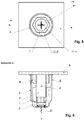
- the protective cap according to the invention in particular for use with threaded bolts, in which the assembly takes place on the side of a component facing the bottom, the possibility is created of draining liquid which has penetrated into the interior of the protective cap or condensation water formed in the cap, for example due to strong temperature fluctuations, from the protective cap .
- the protective cap surrounds the screw bolt S and the nut M in a known manner.
- the influence of gravity leads to an accumulation of the liquid F in the area of the cap head, which is condensation water or in the protective cap between sealing lip 4 and the component B with a rough surface can act.
- the openings in the form of the slots 11.4 then allow the liquid to escape independently due to the force of gravity and their position at the point of the protective cap facing the bottom, so that a build-up of liquid in the protective cap and thus corrosion of the screw bolt surrounded by the protective cap is avoided .
Landscapes
- Engineering & Computer Science (AREA)
- General Engineering & Computer Science (AREA)
- Mechanical Engineering (AREA)
- Pressure Vessels And Lids Thereof (AREA)
- Protection Of Pipes Against Damage, Friction, And Corrosion (AREA)
Abstract
Description
- Die Erfindung betrifft eine Schutzkappe für Gewindebolzen bestehend aus einem Kappenkopf sowie einem Kappenmantel, an dem auf seinem dem Kappenkopf abgewandten stirnseitigen Ende eine Dichtlippe ausgebildet ist.
- Schutzkappen für Schraubverbindungen sind in vielfältiger Weise bekannt. Sie dienen insbesondere dem Korrosionsschutz der abgedeckten Schraubverbindungen. Mit den Kappen soll verhindert werden, dass Feuchtigkeit an die Schraubverbindungen gelangt und die Schraubverbindungen dadurch beschädigt werden. Die Schutzkappen sind üblicherweise aus Kunststoff hergestellt. Eine solche Schutzkappe ist bspw. aus der
DE 10 2005 030 817 A1 bekannt. - Die bekannten Schutzkappen erfüllen die an sie gestellten Aufgaben. Allerdings sind Anwendungsfälle bekannt, bei denen die bekannten Schutzkappen eine Beschädigung der Verschraubung durch Feuchtigkeit nur bedingt verhindern können. Dies ist insbesondere bei Montagesituationen der Fall, bei denen die Schutzkappe auf der dem Boden zugewandten Seite eines Bauteils angebracht ist, sogenannte "Kopfüber-Montage". Bei solchen Einbausituationen kann es zu einer Ansammlung von Flüssigkeit in der Schutzkappe kommen. Dies kann einerseits daraus resultieren, dass das Bauteil, auf dem die Schutzkappe aufliegt, eine raue Oberfläche hat und daher keine ausreichend Abdichtung erfolgen kann. Andererseits kann sich in der Kappe durch starke Temperaturschwankungen Kondenswasser bilden, welches sich dann aufgrund der Schwerkraft im Kopf der Kappe sammelt. Solches Wasser aber auch andere in die Schutzkappe eingedrungene Flüssigkeiten können eine Beschädigung der Schraubbolzen herbeiführen.
- Hier will die Erfindung Abhilfe schaffen. Der Erfindung liegt die Aufgabe zu Grunde, eine Schutzkappe zu schaffen, bei der ein Abführen von in die Schutzkappe eingedrungenen oder in der Schutzkappe gebildeten Flüssigkeiten möglich ist.
- Gemäß der Erfindung wird diese Aufgabe dadurch gelöst, dass an dem Kappenkopf ein Stopfen vorgesehen ist, in dem mindestens eine Öffnung ausgebildet ist.
- Mit der Erfindung ist eine Schutzkappe geschaffen, bei der ein Abführen von in die Schutzkappe eingedrungener oder in der Schutzkappe gebildeter Flüssigkeit möglich ist. Durch die Öffnung besteht die Möglichkeit, dass in der Schutzkappe befindliche Flüssigkeit aufgrund der Schwerkraft bei einer Kopfüber-Montage aus der Schutzkappe austreten kann. Folglich besteht nicht die Gefahr, dass sich die Flüssigkeit in der Schutzkappe sammelt und dadurch die von der Schutzkappe überdeckte Verschraubung Schaden nimmt.
- In Ausgestaltung der Erfindung sind die Öffnungen von Schlitzen gebildet. Diese Ausbildung gewährleistet einerseits ein zuverlässiges Austreten der Flüssigkeit aus der Schutzkappe, andererseits können die Öffnungen dadurch schmal ausgebildet sein, so dass die Gefahr eines Eintretens von Schmutz o. dgl. durch die Öffnungen in die Schutzkappe gering ist.
- Vorteilhaft sind die Schlitze rechtwinklig zueinander ausgerichtet und kreuzen einander. Diese Art, die Öffnungen anzuordnen, gewährleistet eine Erstreckung der Öffnungen in einem großen Bereich des Kappenkopfes, so dass in der Schutzkappe befindliche Flüssigkeit auch aus dem Randbereich des Stopfens abgeführt werden kann.
- In Weiterbildung der Erfindung ist der Stopfen von einer Scheibe gebildet, an die ein Rohrabschnitt angeformt ist, an dessen der Scheibe abgewandten Seite ein Ring ausgebildet ist. Diese Ausbildung ist einerseits konstruktiv einfach daher leicht zu fertigen, andererseits ermöglicht diese Gestaltung eine zuverlässige Anbringung an der Schutzkappe.
- In bevorzugter Weiterbildung der Erfindung liegt die Scheibe in einer Vertiefung im Kappenkopf ein. Hierdurch ist eine bündige Anordnung des Stopfens im Kappenkopf möglich, so dass der Stopfen keine Nachteile für die Verwendung der Schutzkappe im Vergleich zu bekannten Schutzkappen aufweist.
- In vorteilhafter Ausgestaltung ist der Stopfen im Kappenkopf geklemmt gehalten. Durch diese Ausführung ist die Montage des Stopfens sehr einfach möglich. Gleichzeitig bietet das die Möglichkeit, den Stopfen bei Bedarf auszutauschen.
- Bevorzugt ist der Kappenkopf an seinem Ende außen mit einer Schraubhilfe versehen. Die Schraubhilfe vereinfacht die Handhabung sowohl bei der Montage als auch bei der Demontage der Schutzkappe.
- Die Schraubhilfe ist dabei äußerst bevorzugt von einem Außenvielkant gebildet. Die Ausgestaltung in Form eines Außenvielkants ermöglicht dabei einerseits ein einfaches Schrauben mit Hilfe von bekannten Werkzeugen. Andererseits führt die Ausgestaltung als Außenvielkant zu einer größeren Stabilität im Bereich des Kappenkopfes. Die Gefahr einer Beschädigung ist durch das Vorsehen des Außenvielkants reduziert.
- In anderer Ausgestaltung der Erfindung sind auf der Innenseite axiale Stege vorgesehen sind, die radial ausgerichtet, und dass die lichte Weite zwischen gegenüberliegenden Stegen im Wesentlichen dem Durchmesser des Gewindebolzens entspricht. Durch die auf der Innenseite der Kappe vorgesehenen Stege ist es möglich, die Schutzkappe auf das Gewinde des Gewindebolzens aufzuschrauben. Der auf den jeweiligen Durchmesser der Gewindebolzen abgestimmte Abstand zwischen den Stegen ermöglicht dabei ein Einschneiden des Gewindes in die freien Enden der Stege. Es ist daher nicht erforderlich, bereits bei der Herstellung der Schutzkappe ein Gewinde in die Stege einzubringen; vielmehr erfolgt dies selbstschneidend beim Aufschrauben der Kappe auf den jeweiligen Gewindebolzen.
- Andere Weiterbildungen und Ausgestaltungen der Erfindung sind in den übrigen Unteransprüchen angegeben. Ein Ausführungsbeispiel der Erfindung ist in der Zeichnung dargestellt und wird nachfolgend im Einzelnen beschrieben. Es zeigen:
- Fig. 1
- den Schnitt entlang der Linie A-A in
Figur 2 durch eine erfindungs-gemäße Schutzkappe; - Fig. 2
- die Draufsicht auf die in
Figur 1 dargestellte Schutzkappe; - Fig. 3
- den Schnitt entlang der Linie B-B in
Figur 4 durch einen Stopfen; - Fig. 4
- die Draufsicht auf den in
Figur 3 dargestellten Stopfen; - Fig. 5
- die Untersicht auf die erfindungsgemäße Schutzkappe in montiertem Zustand und
- Fig. 6
- den Schnitt entlang der Linie A-A in
Figur 5 durch eine erfindungsgemäße Schutzkappe in montiertem Zustand. - Die als Ausführungsbeispiel gewählte Schutzkappe ist insbesondere zur Anwendung bei Gewindebolzen vorgesehen, bei denen die Montage auf der dem Boden zugewandten Seite eines Bauteils erfolgt, sogenannte "Kopfüber-Montage". Sie besteht aus einem Kappenkopf 1 sowie einem Kappenmantel 2. An dem dem Kappenkopf 1 abgewandten stirnseitigen Ende der Kappe, welches dem jeweiligen Bauteil zugewandt ist, sind eine Absetzlippe 3 sowie eine Dichtlippe 4 ausgebildet. Die Dichtlippe 4 liegt in montiertem Zustand der Schutzkappe auf dem jeweiligen Bauteil auf.
- In Abwandlung des Ausführungsbeispiels besteht die Möglichkeit, dass die Absetzlippe 3 ebenfalls bis auf das Bauteil ragt. In diesem Fall ist die zwischen Absetzlippe 3 und Dichtlippe 4 vorgesehene Rinne 5 als Unterbrechung zwischen den beiden Lippen 3 und 4 zu sehen. Die Rinne 5 bildet dann eine Unterbrechung von Kriechwegen innerhalb der von der Absetzlippe 3 sowie der Dichtlippe 4 gebildeten Dichtfläche, was eine Verbesserung der Dichtwirkung bedeutet, da die Kapillarkräfte die Rinne bei Bauteilen mit glatter Oberfläche nicht überwinden können.
- Auf der Innenseite des Kappenmantels 2 sind axiale Stege 6 vorgesehen, die radial ausgerichtet sind. Die Stege 6 erstrecken sich in Längsrichtung über einen Teil der Höhe der Kappe. Die Stege 6 können sich beispielsweise über ein oder zwei Drittel der Höhe der Kappe erstrecken; auch die Erstreckung über die halbe Höhe der Kappe ist möglich. Die Erstreckung der Stege 6 ist abhängig von der jeweiligen Einbausituation und erfolgt somit in Abhängigkeit der Ausbildung des jeweiligen Gewindebolzens bzw. der Anordnung von Muttern auf dem Gewindebolzen.
- Die Stege 6 sind symmetrisch über den Umfang der Schutzkappe verteilt angeordnet. Im Ausführungsbeispiel sind sechs Stege 6 vorgesehen. An ihren freien Enden können die Stege 6 in Abwandlung des Ausführungsbeispiels spitz ausgebildet sein. Der Abstand zwischen gegenüberliegenden Stegen 6, also die lichte Weite zwischen den Stegen, entspricht im Wesentlichen dem Gewindedurchmesser des Gewindebolzens, den die Kappe schützen soll. Die Abmessungen sind dabei so dimensioniert, dass die freien Enden der Stege 6 einen geringfügig kleineren Abstand zueinander aufweisen als der Außendurchmesser des Gewindes. Hierdurch ist gewährleistet, dass sich das Gewinde des Bolzens beim Aufschrauben der Schutzkappe in die Stege 6 einschneidet.
- Auf der Außenseite des Kappenmantels 2 ist eine Schraubhilfe 7 vorgesehen. Im Ausführungsbeispiel ist die Schraubhilfe 7 am Ende des Kappenkopfes 1 vorgesehen. Die Schraubhilfe 7 ist von einem Außenvielkant gebildet. Im Ausführungsbeispiel handelt es sich um einen Außensechskant. Die Schraubhilfe 7 ist somit in einfacher Weise mit üblichen Werkzeugen handhabbar. Gleichzeitig ist durch den Außenvielkant die Stabilität der Schutzkappe im Vergleich zu bekannten Schutzkappen erhöht.
- Der Kappenkopf 1 ist im Bereich der Schraubhilfe 7 von einer Bohrung 8 durchsetzt. Die Bohrung 8 weist in ihrem dem Kappenmantel 2 abgewandten Bereich eine Verjüngung 9 auf, an die sich eine kreisförmige Vertiefung 10 anschließt, die an der Stirnseite der Schutzkappe ausgebildet ist.
- An dem Kappenkopf 1 ist ein Stopfen 11 vorgesehen. Der Stopfen 11 ist im Ausführungsbeispiel von einer Scheibe 11.1 gebildet. Die Scheibe 11.1 des Stopfens 11 liegt in der Vertiefung 10 im Kappenkopf 1 ein und ist am stirnseitigen Ende des Kappenkopfes 1 angeordnet. Sie schließt daher bündig mit der Stirnseite der Schutzkappe ab. Auf der dem Kappenkopf 1 zugewandten Seite ist an die Scheibe 11.1 ein Rohrabschnitt 11.2 angeformt, an dessen der Scheibe 11.1 abgewandten Seite ein Ring 11.3 ausgebildet ist, dessen Außendurchmesser größer als der des Rohrabschnitts 11.2, jedoch kleiner als der der Scheibe 11.1 ist. In dem Stopfen 11 sind Öffnungen ausgebildet, die im Ausführungsbeispiel von Schlitzen 11.4 gebildet sind. Im Ausführungsbeispiel sind zwei rechtwinklig zueinander ausgerichtete Schlitze 11.4 vorgesehen, die einander kreuzen, wobei der Schnittpunkt der beiden Schlitze 11.4 im Mittelpunkt der Scheibe 11.1 angeordnet ist. Andere Formen der Öffnungen, bspw. in Form einer Lochung, sind ebenfalls möglich.
- Der Stopfen 11 ist im Kappenkopf 1 der Schutzkappe geklemmt gehalten. Dies ist dadurch bewirkt, dass zur Montage des Stopfens 11 der Ring 11.3 durch die Verjüngung 9 gedrückt wird. Sobald der Ring 11.3 die Verjüngung 9 passiert hat, liegt der Ring 11.3 an der die Verjüngung umgebenden Wandung auf der Innenseite der Schutzkappe an (vgl.
Figur 2 ). Somit ist der Stopfen 11 zuverlässig an der Schutzkappe befestigt. Durch die Anordnung des Stopfens 11 im Kappenkopf sind die im Ausführungsbeispiel von den Schlitzen 11.4 gebildeten Öffnungen an dem den Lippen 3 und 4 abgewandten Ende der Schutzkappe vorgesehen. Sie sind folglich am äußersten Ende er Schutzkappe positioniert. - Mit der erfindungsgemäßen Schutzkappe insbesondere zur Anwendung bei Gewindebolzen, bei denen die Montage auf der dem Boden zugewandten Seite eines Bauteils erfolgt, ist die Möglichkeit geschaffen, in das Innere der Schutzkappe eingedrungene Flüssigkeit oder in der Kappe beispielsweise durch starke Temperaturschwankungen gebildetes Kondenswasser aus der Schutzkappe abzuführen. Bei der sogenannten "Kopfüber-Montage", wie sie in den
Figuren 5 und 6 dargestellt ist, umgibt die Schutzkappe in bekannter Weise den Schraubbolzen S sowie die Mutter M. Dabei führt der Einfluss der Schwerkraft zu einer Ansammlung der Flüssigkeit F im Bereich des Kappenkopfes, bei welcher es sich um Kondenswasser oder auch um in die Schutzkappe zwischen Dichtlippe 4 und dem Bauteil B mit rauer Oberfläche eingedrungene Flüssigkeit handeln kann. Die Öffnungen in Form der Schlitze 11.4 ermöglichen dann aufgrund der Schwerkraft und ihrer Position am äußersten dem Boden zugewandten Punkt der Schutzkappe das selbstständige Entweichen der Flüssigkeit, so dass ein Anstauen von Flüssigkeit in der Schutzkappe und damit eine Korrosion des von der Schutzkappe umgebenen Schraubbolzens vermieden ist.
Claims (9)
- Schutzkappe für Gewindebolzen bestehend aus einem Kappenkopf (1) sowie einem Kappenmantel (2), an dem auf seinem dem Kappenkopf (1) abgewandten stirnseitigen Ende eine Dichtlippe (4) ausgebildet ist, dadurch gekennzeichnet, dass an dem Kappenkopf (1) ein Stopfen (11) vorgesehen ist, in dem mindestens eine Öffnung ausgebildet ist.
- Schutzkappe nach Anspruch 1, dadurch gekennzeichnet, dass die Öffnungen von Schlitzen (11.4) gebildet sind.
- Schutzkappe nach Anspruch 2, dadurch gekennzeichnet, dass die Schlitze (11.4) rechtwinklig zueinander ausgerichtet sind und einander kreuzen.
- Schutzkappe nach einem der Ansprüche 1 bis 3, dadurch gekennzeichnet, dass der Stopfen (11) von einer Scheibe (11.1) gebildet ist, an die ein Rohrabschnitt (11.2) angeformt ist, an dessen der Scheibe (11.1) abgewandten Seite ein Ring (11.3) ausgebildet ist.
- Schutzkappe nach Anspruch 4, dadurch gekennzeichnet, dass die Scheibe (11.1) in einer Vertiefung (10) im Kappenkopf (1) einliegt.
- Schutzkappe nach einem der Ansprüche 1 bis 5, dadurch gekennzeichnet, dass der Stopfen (11) im Kappenkopf (1) geklemmt gehalten ist.
- Schutzkappe nach einem der Ansprüche 1 bis 6, dadurch gekennzeichnet, dass der Kappenkopf (1) an seinem Ende außen mit einer Schraubhilfe (7) versehen ist.
- Schutzkappe nach Anspruch 7, dadurch gekennzeichnet, dass die Schraubhilfe (7) von einem Außenvielkant gebildet ist.
- Schutzkappe nach einem der Ansprüche 1 bis 8, dadurch gekennzeichnet, dass auf der Innenseite axiale Stege (6) vorgesehen sind, die radial ausgerichtet sind, und dass die lichte Weite zwischen gegenüberliegenden Stegen (6) im Wesentlichen dem Durchmesser des Gewindebolzens entspricht.
Applications Claiming Priority (1)
| Application Number | Priority Date | Filing Date | Title |
|---|---|---|---|
| DE102019105634.9A DE102019105634B3 (de) | 2019-03-06 | 2019-03-06 | Schutzkappe für Gewindebolzen |
Publications (2)
| Publication Number | Publication Date |
|---|---|
| EP3705739A1 true EP3705739A1 (de) | 2020-09-09 |
| EP3705739B1 EP3705739B1 (de) | 2024-01-24 |
Family
ID=69742690
Family Applications (1)
| Application Number | Title | Priority Date | Filing Date |
|---|---|---|---|
| EP20159681.4A Active EP3705739B1 (de) | 2019-03-06 | 2020-02-27 | Schutzkappe für gewindebolzen |
Country Status (5)
| Country | Link |
|---|---|
| EP (1) | EP3705739B1 (de) |
| DE (1) | DE102019105634B3 (de) |
| DK (1) | DK3705739T3 (de) |
| ES (1) | ES2974784T3 (de) |
| FI (1) | FI3705739T3 (de) |
Cited By (1)
| Publication number | Priority date | Publication date | Assignee | Title |
|---|---|---|---|---|
| CN115978075A (zh) * | 2022-12-05 | 2023-04-18 | 中国大唐集团科学技术研究总院有限公司西北电力试验研究院 | 一种风机塔筒基础螺栓防锈罩 |
Citations (6)
| Publication number | Priority date | Publication date | Assignee | Title |
|---|---|---|---|---|
| US6273658B1 (en) * | 2000-01-27 | 2001-08-14 | S. Allen Patterson | Enclosure for protecting a lug and lug nut |
| DE102005030817A1 (de) | 2005-07-01 | 2007-01-04 | Radolid Thiel Gmbh | Schutzkappe für Schraubverbindungen sowie Verfahren zur Herstellung von Schutzkappen für Schraubverbindungen |
| GB2511299A (en) * | 2013-03-01 | 2014-09-03 | Albertus Abraham Petrus De Groot | Indicator swinging moisture out |
| US20150035346A1 (en) * | 2013-08-02 | 2015-02-05 | Ming-Cheng Wang | Wheel cover for truck front wheels |
| GB2542418A (en) * | 2015-09-18 | 2017-03-22 | Abraham Petrus De Groot Albertus | A capping device for wheel mounted members with an integrated reflector |
| WO2018041318A1 (en) * | 2016-08-30 | 2018-03-08 | Stiesdal Offshore Technologies A/S | Protection system for a threaded fastener a method for installation, inspection and maintenance of such protection system |
Family Cites Families (1)
| Publication number | Priority date | Publication date | Assignee | Title |
|---|---|---|---|---|
| DE7238928U (de) | 1973-01-25 | Thiel H | Schutzkappe für Verschraubung |
-
2019
- 2019-03-06 DE DE102019105634.9A patent/DE102019105634B3/de active Active
-
2020
- 2020-02-27 EP EP20159681.4A patent/EP3705739B1/de active Active
- 2020-02-27 ES ES20159681T patent/ES2974784T3/es active Active
- 2020-02-27 FI FIEP20159681.4T patent/FI3705739T3/fi active
- 2020-02-27 DK DK20159681.4T patent/DK3705739T3/da active
Patent Citations (6)
| Publication number | Priority date | Publication date | Assignee | Title |
|---|---|---|---|---|
| US6273658B1 (en) * | 2000-01-27 | 2001-08-14 | S. Allen Patterson | Enclosure for protecting a lug and lug nut |
| DE102005030817A1 (de) | 2005-07-01 | 2007-01-04 | Radolid Thiel Gmbh | Schutzkappe für Schraubverbindungen sowie Verfahren zur Herstellung von Schutzkappen für Schraubverbindungen |
| GB2511299A (en) * | 2013-03-01 | 2014-09-03 | Albertus Abraham Petrus De Groot | Indicator swinging moisture out |
| US20150035346A1 (en) * | 2013-08-02 | 2015-02-05 | Ming-Cheng Wang | Wheel cover for truck front wheels |
| GB2542418A (en) * | 2015-09-18 | 2017-03-22 | Abraham Petrus De Groot Albertus | A capping device for wheel mounted members with an integrated reflector |
| WO2018041318A1 (en) * | 2016-08-30 | 2018-03-08 | Stiesdal Offshore Technologies A/S | Protection system for a threaded fastener a method for installation, inspection and maintenance of such protection system |
Cited By (1)
| Publication number | Priority date | Publication date | Assignee | Title |
|---|---|---|---|---|
| CN115978075A (zh) * | 2022-12-05 | 2023-04-18 | 中国大唐集团科学技术研究总院有限公司西北电力试验研究院 | 一种风机塔筒基础螺栓防锈罩 |
Also Published As
| Publication number | Publication date |
|---|---|
| FI3705739T3 (fi) | 2024-03-28 |
| ES2974784T3 (es) | 2024-07-01 |
| DE102019105634B3 (de) | 2020-05-20 |
| DK3705739T3 (da) | 2024-04-22 |
| EP3705739B1 (de) | 2024-01-24 |
Similar Documents
| Publication | Publication Date | Title |
|---|---|---|
| DE4033763C2 (de) | Vorrichtung zum Sichern einer in einer Öffnung in einer Verkleidung aufgenommenen Mutter | |
| EP0742873B1 (de) | Montageeinheit aus einem montageteil, einem fixierteil und einer hülse als verliersicherung sowie herstellungsverfahren der montageeinheit | |
| EP1903223B1 (de) | Mutter aus Kunststoff | |
| EP3286440B2 (de) | Vorrichtung zum festlegen an einem bauteil | |
| EP3387270B1 (de) | Befestigungselement | |
| EP2982874B1 (de) | Schraubdom zum befestigen eines bauteils | |
| DE102009012243B4 (de) | Stanzmutter, Stanzmutter-Vorrichtung und Stanzmutter-Blechverbindung | |
| EP3705739B1 (de) | Schutzkappe für gewindebolzen | |
| DE3939092C2 (de) | Verschlußkörper für Gewindebohrungen | |
| DE3420646A1 (de) | Schraube mit stroemungskanal | |
| DE102016209395A1 (de) | Befestigungselement für den Toleranzausgleich | |
| DE3711429C2 (de) | Vorrichtung zur Schalldämpfung an einer sanitären Armatur | |
| DE102012015504B4 (de) | Bauteil mit Einschraubabschnitt und damit ausgestattete Baugruppe | |
| DE3413792C1 (de) | Verbindung für miteinander verschraubbare Rohre | |
| DE102012101060A1 (de) | Korrosionsschutzkappe | |
| DE10052915B4 (de) | Mutter mit einer Klemmsicherung | |
| DE3403128A1 (de) | Schraubverbindung | |
| DE10048975C1 (de) | Mutter aus Kunststoff | |
| DE10328692A1 (de) | Verbindungselement zur festen jedoch lösbaren Verbindung eines Montageteils mit einem zweiten Bauteil | |
| DE9114257U1 (de) | Rohrverbinder | |
| DE19724242C2 (de) | Mutter | |
| DE102006014477B4 (de) | Verbindungssystem mit Entwässerungsnut | |
| EP3017853B1 (de) | Filterdüse und Filterdüsensystem | |
| DE4118250A1 (de) | Verstrebungsvorrichtung fuer luftkanaele aus blech | |
| DE10163559B4 (de) | Kugelzapfen |
Legal Events
| Date | Code | Title | Description |
|---|---|---|---|
| PUAI | Public reference made under article 153(3) epc to a published international application that has entered the european phase |
Free format text: ORIGINAL CODE: 0009012 |
|
| STAA | Information on the status of an ep patent application or granted ep patent |
Free format text: STATUS: THE APPLICATION HAS BEEN PUBLISHED |
|
| AK | Designated contracting states |
Kind code of ref document: A1 Designated state(s): AL AT BE BG CH CY CZ DE DK EE ES FI FR GB GR HR HU IE IS IT LI LT LU LV MC MK MT NL NO PL PT RO RS SE SI SK SM TR |
|
| AX | Request for extension of the european patent |
Extension state: BA ME |
|
| STAA | Information on the status of an ep patent application or granted ep patent |
Free format text: STATUS: REQUEST FOR EXAMINATION WAS MADE |
|
| 17P | Request for examination filed |
Effective date: 20210209 |
|
| RBV | Designated contracting states (corrected) |
Designated state(s): AL AT BE BG CH CY CZ DE DK EE ES FI FR GB GR HR HU IE IS IT LI LT LU LV MC MK MT NL NO PL PT RO RS SE SI SK SM TR |
|
| STAA | Information on the status of an ep patent application or granted ep patent |
Free format text: STATUS: EXAMINATION IS IN PROGRESS |
|
| 17Q | First examination report despatched |
Effective date: 20220921 |
|
| 17Q | First examination report despatched |
Effective date: 20221104 |
|
| GRAP | Despatch of communication of intention to grant a patent |
Free format text: ORIGINAL CODE: EPIDOSNIGR1 |
|
| STAA | Information on the status of an ep patent application or granted ep patent |
Free format text: STATUS: GRANT OF PATENT IS INTENDED |
|
| RIC1 | Information provided on ipc code assigned before grant |
Ipc: F16B 33/00 20060101ALN20231005BHEP Ipc: F16B 37/14 20060101AFI20231005BHEP |
|
| INTG | Intention to grant announced |
Effective date: 20231019 |
|
| GRAS | Grant fee paid |
Free format text: ORIGINAL CODE: EPIDOSNIGR3 |
|
| GRAA | (expected) grant |
Free format text: ORIGINAL CODE: 0009210 |
|
| STAA | Information on the status of an ep patent application or granted ep patent |
Free format text: STATUS: THE PATENT HAS BEEN GRANTED |
|
| AK | Designated contracting states |
Kind code of ref document: B1 Designated state(s): AL AT BE BG CH CY CZ DE DK EE ES FI FR GB GR HR HU IE IS IT LI LT LU LV MC MK MT NL NO PL PT RO RS SE SI SK SM TR |
|
| REG | Reference to a national code |
Ref country code: GB Ref legal event code: FG4D Free format text: NOT ENGLISH |
|
| REG | Reference to a national code |
Ref country code: CH Ref legal event code: EP |
|
| REG | Reference to a national code |
Ref country code: DE Ref legal event code: R096 Ref document number: 502020006796 Country of ref document: DE |
|
| REG | Reference to a national code |
Ref country code: IE Ref legal event code: FG4D Free format text: LANGUAGE OF EP DOCUMENT: GERMAN |
|
| REG | Reference to a national code |
Ref country code: FI Ref legal event code: FGE |
|
| REG | Reference to a national code |
Ref country code: NL Ref legal event code: FP |
|
| REG | Reference to a national code |
Ref country code: DK Ref legal event code: T3 Effective date: 20240418 |
|
| REG | Reference to a national code |
Ref country code: SE Ref legal event code: TRGR |
|
| REG | Reference to a national code |
Ref country code: LT Ref legal event code: MG9D |
|
| P01 | Opt-out of the competence of the unified patent court (upc) registered |
Effective date: 20240419 |
|
| PG25 | Lapsed in a contracting state [announced via postgrant information from national office to epo] |
Ref country code: IS Free format text: LAPSE BECAUSE OF FAILURE TO SUBMIT A TRANSLATION OF THE DESCRIPTION OR TO PAY THE FEE WITHIN THE PRESCRIBED TIME-LIMIT Effective date: 20240524 |
|
| REG | Reference to a national code |
Ref country code: ES Ref legal event code: FG2A Ref document number: 2974784 Country of ref document: ES Kind code of ref document: T3 Effective date: 20240701 |
|
| PG25 | Lapsed in a contracting state [announced via postgrant information from national office to epo] |
Ref country code: LT Free format text: LAPSE BECAUSE OF FAILURE TO SUBMIT A TRANSLATION OF THE DESCRIPTION OR TO PAY THE FEE WITHIN THE PRESCRIBED TIME-LIMIT Effective date: 20240124 |
|
| PG25 | Lapsed in a contracting state [announced via postgrant information from national office to epo] |
Ref country code: GR Free format text: LAPSE BECAUSE OF FAILURE TO SUBMIT A TRANSLATION OF THE DESCRIPTION OR TO PAY THE FEE WITHIN THE PRESCRIBED TIME-LIMIT Effective date: 20240425 |
|
| PG25 | Lapsed in a contracting state [announced via postgrant information from national office to epo] |
Ref country code: HR Free format text: LAPSE BECAUSE OF FAILURE TO SUBMIT A TRANSLATION OF THE DESCRIPTION OR TO PAY THE FEE WITHIN THE PRESCRIBED TIME-LIMIT Effective date: 20240124 Ref country code: RS Free format text: LAPSE BECAUSE OF FAILURE TO SUBMIT A TRANSLATION OF THE DESCRIPTION OR TO PAY THE FEE WITHIN THE PRESCRIBED TIME-LIMIT Effective date: 20240424 |
|
| PG25 | Lapsed in a contracting state [announced via postgrant information from national office to epo] |
Ref country code: RS Free format text: LAPSE BECAUSE OF FAILURE TO SUBMIT A TRANSLATION OF THE DESCRIPTION OR TO PAY THE FEE WITHIN THE PRESCRIBED TIME-LIMIT Effective date: 20240424 Ref country code: LT Free format text: LAPSE BECAUSE OF FAILURE TO SUBMIT A TRANSLATION OF THE DESCRIPTION OR TO PAY THE FEE WITHIN THE PRESCRIBED TIME-LIMIT Effective date: 20240124 Ref country code: IS Free format text: LAPSE BECAUSE OF FAILURE TO SUBMIT A TRANSLATION OF THE DESCRIPTION OR TO PAY THE FEE WITHIN THE PRESCRIBED TIME-LIMIT Effective date: 20240524 Ref country code: HR Free format text: LAPSE BECAUSE OF FAILURE TO SUBMIT A TRANSLATION OF THE DESCRIPTION OR TO PAY THE FEE WITHIN THE PRESCRIBED TIME-LIMIT Effective date: 20240124 Ref country code: GR Free format text: LAPSE BECAUSE OF FAILURE TO SUBMIT A TRANSLATION OF THE DESCRIPTION OR TO PAY THE FEE WITHIN THE PRESCRIBED TIME-LIMIT Effective date: 20240425 Ref country code: BG Free format text: LAPSE BECAUSE OF FAILURE TO SUBMIT A TRANSLATION OF THE DESCRIPTION OR TO PAY THE FEE WITHIN THE PRESCRIBED TIME-LIMIT Effective date: 20240124 |
|
| PGFP | Annual fee paid to national office [announced via postgrant information from national office to epo] |
Ref country code: FI Payment date: 20240416 Year of fee payment: 5 |
|
| PG25 | Lapsed in a contracting state [announced via postgrant information from national office to epo] |
Ref country code: PT Free format text: LAPSE BECAUSE OF FAILURE TO SUBMIT A TRANSLATION OF THE DESCRIPTION OR TO PAY THE FEE WITHIN THE PRESCRIBED TIME-LIMIT Effective date: 20240524 Ref country code: PL Free format text: LAPSE BECAUSE OF FAILURE TO SUBMIT A TRANSLATION OF THE DESCRIPTION OR TO PAY THE FEE WITHIN THE PRESCRIBED TIME-LIMIT Effective date: 20240124 |
|
| PG25 | Lapsed in a contracting state [announced via postgrant information from national office to epo] |
Ref country code: PT Free format text: LAPSE BECAUSE OF FAILURE TO SUBMIT A TRANSLATION OF THE DESCRIPTION OR TO PAY THE FEE WITHIN THE PRESCRIBED TIME-LIMIT Effective date: 20240524 Ref country code: PL Free format text: LAPSE BECAUSE OF FAILURE TO SUBMIT A TRANSLATION OF THE DESCRIPTION OR TO PAY THE FEE WITHIN THE PRESCRIBED TIME-LIMIT Effective date: 20240124 Ref country code: LV Free format text: LAPSE BECAUSE OF FAILURE TO SUBMIT A TRANSLATION OF THE DESCRIPTION OR TO PAY THE FEE WITHIN THE PRESCRIBED TIME-LIMIT Effective date: 20240124 |
|
| REG | Reference to a national code |
Ref country code: CH Ref legal event code: PL |
|
| PG25 | Lapsed in a contracting state [announced via postgrant information from national office to epo] |
Ref country code: SM Free format text: LAPSE BECAUSE OF FAILURE TO SUBMIT A TRANSLATION OF THE DESCRIPTION OR TO PAY THE FEE WITHIN THE PRESCRIBED TIME-LIMIT Effective date: 20240124 |
|
| PG25 | Lapsed in a contracting state [announced via postgrant information from national office to epo] |
Ref country code: LU Free format text: LAPSE BECAUSE OF NON-PAYMENT OF DUE FEES Effective date: 20240227 |
|
| PG25 | Lapsed in a contracting state [announced via postgrant information from national office to epo] |
Ref country code: CH Free format text: LAPSE BECAUSE OF NON-PAYMENT OF DUE FEES Effective date: 20240229 |
|
| PG25 | Lapsed in a contracting state [announced via postgrant information from national office to epo] |
Ref country code: EE Free format text: LAPSE BECAUSE OF FAILURE TO SUBMIT A TRANSLATION OF THE DESCRIPTION OR TO PAY THE FEE WITHIN THE PRESCRIBED TIME-LIMIT Effective date: 20240124 Ref country code: CZ Free format text: LAPSE BECAUSE OF FAILURE TO SUBMIT A TRANSLATION OF THE DESCRIPTION OR TO PAY THE FEE WITHIN THE PRESCRIBED TIME-LIMIT Effective date: 20240124 |
|
| REG | Reference to a national code |
Ref country code: DE Ref legal event code: R097 Ref document number: 502020006796 Country of ref document: DE |
|
| PG25 | Lapsed in a contracting state [announced via postgrant information from national office to epo] |
Ref country code: SK Free format text: LAPSE BECAUSE OF FAILURE TO SUBMIT A TRANSLATION OF THE DESCRIPTION OR TO PAY THE FEE WITHIN THE PRESCRIBED TIME-LIMIT Effective date: 20240124 |
|
| PG25 | Lapsed in a contracting state [announced via postgrant information from national office to epo] |
Ref country code: SM Free format text: LAPSE BECAUSE OF FAILURE TO SUBMIT A TRANSLATION OF THE DESCRIPTION OR TO PAY THE FEE WITHIN THE PRESCRIBED TIME-LIMIT Effective date: 20240124 Ref country code: SK Free format text: LAPSE BECAUSE OF FAILURE TO SUBMIT A TRANSLATION OF THE DESCRIPTION OR TO PAY THE FEE WITHIN THE PRESCRIBED TIME-LIMIT Effective date: 20240124 Ref country code: LU Free format text: LAPSE BECAUSE OF NON-PAYMENT OF DUE FEES Effective date: 20240227 Ref country code: EE Free format text: LAPSE BECAUSE OF FAILURE TO SUBMIT A TRANSLATION OF THE DESCRIPTION OR TO PAY THE FEE WITHIN THE PRESCRIBED TIME-LIMIT Effective date: 20240124 Ref country code: CZ Free format text: LAPSE BECAUSE OF FAILURE TO SUBMIT A TRANSLATION OF THE DESCRIPTION OR TO PAY THE FEE WITHIN THE PRESCRIBED TIME-LIMIT Effective date: 20240124 Ref country code: CH Free format text: LAPSE BECAUSE OF NON-PAYMENT OF DUE FEES Effective date: 20240229 |
|
| PG25 | Lapsed in a contracting state [announced via postgrant information from national office to epo] |
Ref country code: MC Free format text: LAPSE BECAUSE OF FAILURE TO SUBMIT A TRANSLATION OF THE DESCRIPTION OR TO PAY THE FEE WITHIN THE PRESCRIBED TIME-LIMIT Effective date: 20240124 |
|
| PG25 | Lapsed in a contracting state [announced via postgrant information from national office to epo] |
Ref country code: MC Free format text: LAPSE BECAUSE OF FAILURE TO SUBMIT A TRANSLATION OF THE DESCRIPTION OR TO PAY THE FEE WITHIN THE PRESCRIBED TIME-LIMIT Effective date: 20240124 |
|
| PLBE | No opposition filed within time limit |
Free format text: ORIGINAL CODE: 0009261 |
|
| STAA | Information on the status of an ep patent application or granted ep patent |
Free format text: STATUS: NO OPPOSITION FILED WITHIN TIME LIMIT |
|
| PG25 | Lapsed in a contracting state [announced via postgrant information from national office to epo] |
Ref country code: IT Free format text: LAPSE BECAUSE OF FAILURE TO SUBMIT A TRANSLATION OF THE DESCRIPTION OR TO PAY THE FEE WITHIN THE PRESCRIBED TIME-LIMIT Effective date: 20240124 |
|
| REG | Reference to a national code |
Ref country code: BE Ref legal event code: MM Effective date: 20240229 |
|
| PG25 | Lapsed in a contracting state [announced via postgrant information from national office to epo] |
Ref country code: IT Free format text: LAPSE BECAUSE OF FAILURE TO SUBMIT A TRANSLATION OF THE DESCRIPTION OR TO PAY THE FEE WITHIN THE PRESCRIBED TIME-LIMIT Effective date: 20240124 |
|
| 26N | No opposition filed |
Effective date: 20241025 |
|
| PG25 | Lapsed in a contracting state [announced via postgrant information from national office to epo] |
Ref country code: BE Free format text: LAPSE BECAUSE OF NON-PAYMENT OF DUE FEES Effective date: 20240229 |
|
| PG25 | Lapsed in a contracting state [announced via postgrant information from national office to epo] |
Ref country code: IE Free format text: LAPSE BECAUSE OF NON-PAYMENT OF DUE FEES Effective date: 20240227 |
|
| PG25 | Lapsed in a contracting state [announced via postgrant information from national office to epo] |
Ref country code: IE Free format text: LAPSE BECAUSE OF NON-PAYMENT OF DUE FEES Effective date: 20240227 Ref country code: BE Free format text: LAPSE BECAUSE OF NON-PAYMENT OF DUE FEES Effective date: 20240229 |
|
| PGFP | Annual fee paid to national office [announced via postgrant information from national office to epo] |
Ref country code: NL Payment date: 20250220 Year of fee payment: 6 |
|
| PGFP | Annual fee paid to national office [announced via postgrant information from national office to epo] |
Ref country code: DE Payment date: 20250218 Year of fee payment: 6 |
|
| PGFP | Annual fee paid to national office [announced via postgrant information from national office to epo] |
Ref country code: DK Payment date: 20250219 Year of fee payment: 6 |
|
| PGFP | Annual fee paid to national office [announced via postgrant information from national office to epo] |
Ref country code: ES Payment date: 20250318 Year of fee payment: 6 |
|
| PGFP | Annual fee paid to national office [announced via postgrant information from national office to epo] |
Ref country code: SE Payment date: 20250219 Year of fee payment: 6 |
|
| PGFP | Annual fee paid to national office [announced via postgrant information from national office to epo] |
Ref country code: NO Payment date: 20250218 Year of fee payment: 6 |
|
| PG25 | Lapsed in a contracting state [announced via postgrant information from national office to epo] |
Ref country code: SI Free format text: LAPSE BECAUSE OF FAILURE TO SUBMIT A TRANSLATION OF THE DESCRIPTION OR TO PAY THE FEE WITHIN THE PRESCRIBED TIME-LIMIT Effective date: 20240124 |
|
| PGFP | Annual fee paid to national office [announced via postgrant information from national office to epo] |
Ref country code: AT Payment date: 20250417 Year of fee payment: 5 |
|
| PGFP | Annual fee paid to national office [announced via postgrant information from national office to epo] |
Ref country code: FR Payment date: 20250219 Year of fee payment: 6 |
|
| PGFP | Annual fee paid to national office [announced via postgrant information from national office to epo] |
Ref country code: GB Payment date: 20250220 Year of fee payment: 6 |
|
| PGFP | Annual fee paid to national office [announced via postgrant information from national office to epo] |
Ref country code: TR Payment date: 20250218 Year of fee payment: 6 |
|
| PG25 | Lapsed in a contracting state [announced via postgrant information from national office to epo] |
Ref country code: RO Free format text: LAPSE BECAUSE OF FAILURE TO SUBMIT A TRANSLATION OF THE DESCRIPTION OR TO PAY THE FEE WITHIN THE PRESCRIBED TIME-LIMIT Effective date: 20240124 |
|
| PG25 | Lapsed in a contracting state [announced via postgrant information from national office to epo] |
Ref country code: CY Free format text: LAPSE BECAUSE OF FAILURE TO SUBMIT A TRANSLATION OF THE DESCRIPTION OR TO PAY THE FEE WITHIN THE PRESCRIBED TIME-LIMIT; INVALID AB INITIO Effective date: 20200227 |
|
| PG25 | Lapsed in a contracting state [announced via postgrant information from national office to epo] |
Ref country code: HU Free format text: LAPSE BECAUSE OF FAILURE TO SUBMIT A TRANSLATION OF THE DESCRIPTION OR TO PAY THE FEE WITHIN THE PRESCRIBED TIME-LIMIT; INVALID AB INITIO Effective date: 20200227 |
|
| PG25 | Lapsed in a contracting state [announced via postgrant information from national office to epo] |
Ref country code: FI Free format text: LAPSE BECAUSE OF NON-PAYMENT OF DUE FEES Effective date: 20250227 |